User Manual
Spring series LFP Battery
SE-F16
Issue: 06
Date:20250807

1
How to Use This Manual
Read the manual and other related documents before performing any operation on the battery.
Documents must be stored carefully and be always available.
Contents may be periodically updated or revised due to product development. The information in this
manual is subject to change without notice.
All Rights Reserved
No part of this document can be reproduced in any form or by any means without the formal permission
of the manufacturer.
Trademarks and Permissions
Trademarks used in this manual are owned by the manufacturer. All other trademarks or registered
trademarks mentioned in this manual are owned by their respective owners.
Software Licenses
* It is prohibited to use data contained in firmware or software developed by the manufacturer , in part
or in full, for commercial purposes by any means.
* It is prohibited to perform reverse engineering, cracking, or any other operations that compromise the
original program design of the software developed by the manufacturer.
Disclaimer
The manufacturer shall not be liable for personal injury, property loss, product damage and subsequent
losses under the following circumstances:
* Damages caused by force majeure, including earthquake, flood, volcanic eruption, mudslide,, lightning,
fire, war, military conflict,typhoon, hurricane, and so on.
* Failure to comply with the provisions of this manual.
* The installation, operation and storage environment does not meet the relevant international, national
or regional standards;
* Incorrect use of this product.
* Unauthorized or unqualified personnel repair the product, disassembly the rack and perform other
operations.
* Use of unapproved spare parts.
* Unauthorized modifications or technical changes to the product or software.
* Incorrect shipment by yourself or the third party commissioned by you.
* Unsatisfactory materials and tools from you own that do not meet the relevant international, national
or regional standards.
* Damage caused by yourself or the third party's negligence, intent, gross negligence, or improper
operation.

2
Contents
1 Safety Instructions............................................................................................................................................................... 4
1.1 Terms and Symbols
...............................................................................................................................................4
1.2 Safety Rules
...............................................................................................................................................................6
2 Product Description.............................................................................................................................................................7
2.1 Product Features
.....................................................................................................................................................7
2.2 Application Scenarios
...........................................................................................................................................7
2.3 Model Description
.................................................................................................................................................8
2.3.1 SE-F16-L........................................................................................................................................................... 8
2.3.2 SE-F16-E...........................................................................................................................................................9
2.3.3 SE-F16-C........................................................................................................................................................10
2.4 Product Overview
................................................................................................................................................ 12
3 Preparation for Installation
......................................................................................................................................... 14
3.1
Unpacking List........................................................................................................................................................ 14
3.2 Required Tools ........................................................................................................................................................16
3.3 Safety Gear ............................................................................................................................................................... 16
4 Installation Instructions...................................................................................................................................................18
4.1 Installation Personnel
........................................................................................................................................ 18
4.2 Installation Environment
.................................................................................................................................. 19
4.3 Selection of Installation Sites
.........................................................................................................................22
4.5 Mounting the Wheels (Optional)
.................................................................................................................23
4.6 Installing the Battery
..........................................................................................................................................24
4.6.1 Wall-mounted/
Floor-mounted..................................................................................................................24
4.6.2 Stack-mounted..............................................................................................................................................27
5. Electrical Connection.......................................................................................................................................................29
5.1 System Connection Precautions...................................................................................................................... 29
5.2 Preparation before Wiring..................................................................................................................................29
5.3 Parallel Mode 1 .......................................................................................................................................................31
5.4 Grounding.................................................................................................................................................................33
6 Power on/off the Product...............................................................................................................................................33
6.1 Power on/off the Product
................................................................................................................................33
6.2 Buzzer
........................................................................................................................................................................34
6.3 How to utilize your APP?
..................................................................................................................................35
7 Inspection, Cleaning and Maintenance.....................................................................................................................36
7.1 General Information
........................................................................................................................................... 36
7.2 Inspection
................................................................................................................................................................36
7.3 Cleaning
................................................................................................................................................................... 36
8 Storage...................................................................................................................................................................................37
9 Troubleshooting.................................................................................................................................................................38

3
10 Technical Specifications................................................................................................................................................40
11 Environmental Disposal ................................................................................................................................................ 41
12 Transportation Requirements................................................................................................................................... 42
4
1 Safety Instructions
Warning!
Read and follow carefully all safety warnings and all instructions . Failure to do so may result in electrical
shock, fire, serious injury, or death. Save these instructions for future reference.
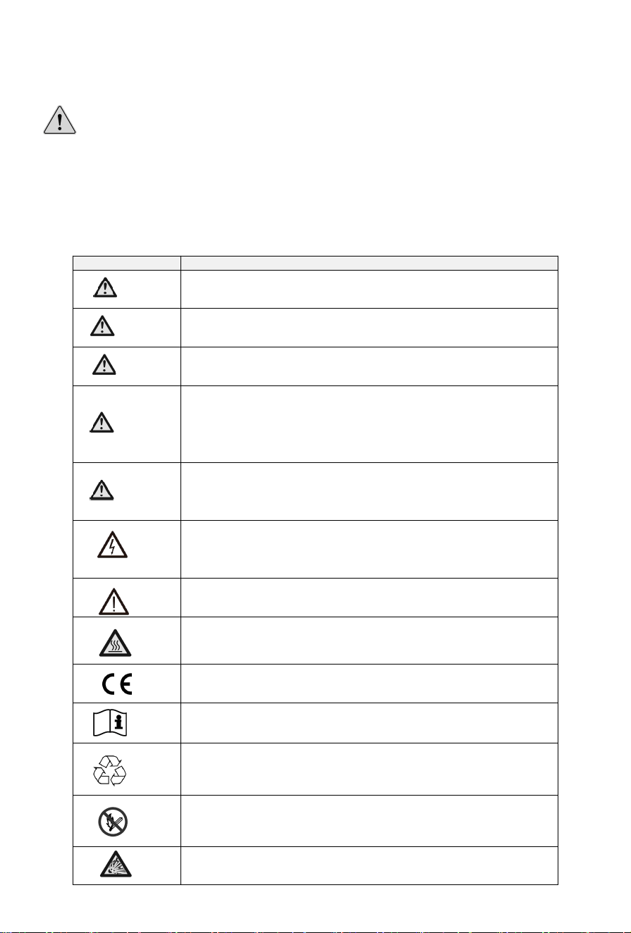
1.1 Terms and Symbols
Terms /Symbols Description
Danger
Indicates a hazard with a high level of risk which, if not avoided, will
result in death or serious injury.
Warning
Indicates a hazard with a medium level of risk which, if not avoided,
will result in death or serious injury.
Caution
Indicates a hazard with a low level of risk which, if not avoided, will
result in minor or moderate injury.
Notice
Indicates a potentially hazardous situation which, if not avoided,
could results in equipment damage, data loss, performance
deterioration, or unanticipated results. NOTICE is used to address
practices not related to personal injury.
Note
Supplements the important information in the main text. NOTE is
used to address information not related to personal injury,
equipment damage, and environment deterioration.
Caution , risk of electric shock symbol indicates important safety
instructions , which if not correctly followed , could result in electric
shock.
The DC input terminals of the inverter must not be grounded.
Surface high temperature , Please do not touch the inverter case .
CE mark of conformity
Please read the instructions carefully before use .
Indicate that this product is recyclable
Do not place near open fire or incinerate. Do not use near heaters or
hot temperature source.
Attention! The risk of explosion.
5
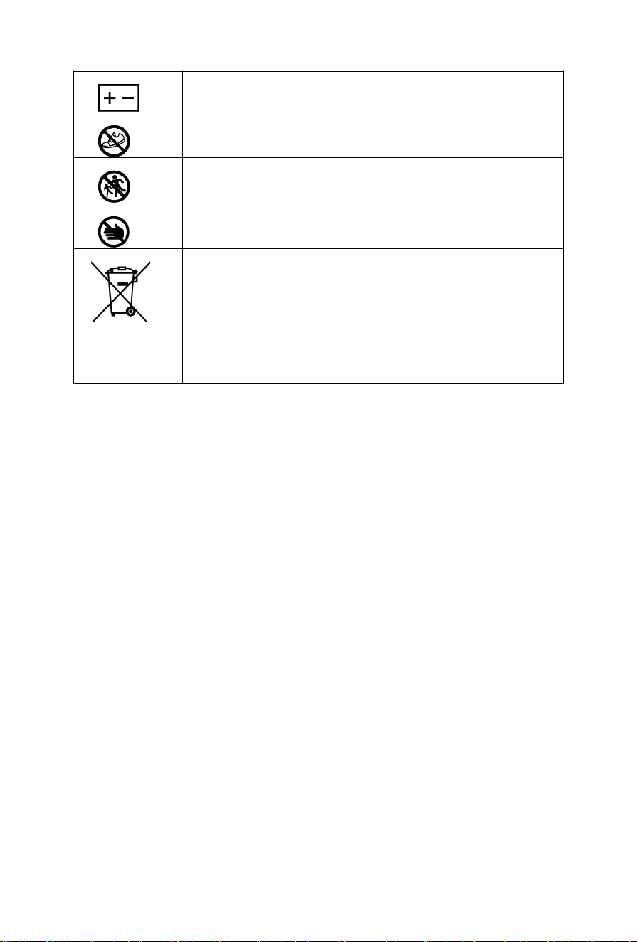
Li-ion battery
Do not tread
Do not run and chase
Do not touch with your palm
Symbol for the marking of electrical and electronics devices
according to Directive 2002/96/ EC. Indicates that the device ,
accessories and the packaging must not be disposed as unsorted
municipal waste and must be collected separately at the end of the
usage . Please follow Local Ordinances or Regulations for disposal or
contact an authorized representative of the manufacturer for
information concerning the decommissioning of equipment.

6
1.2 Safety Rules
1)
After unpacking, please check product and packing list first, if product is damaged or lack of parts,
please contact with the local retailer.
2)
Before installation, be sure to cut o
ff
the grid power and make sure the battery is in the turned-o
ff
mode.
3)
Wiring must be correct. Be careful to negative pole and positive of cable and terminals. Make sure
no short circuit with the external device.
4)
It is prohibited to connect the battery and AC power directly.
5)
Please ensured the electrical parameters of battery system are compatible to related equipment.
6)
Do not allow the terminals to contact exposed wire or metal.
7)
Keep out of reach of children or animals.
8)
Do not place batteries near fire, heater or high temperature sources. This will reduce the risk of
explosion or possible injury.
9)
Batteries can explode in the presence of a source of ignition, such as open flame. An exploded
battery can propel debris and chemicals. If occurs, flush with water immediately.
10)
Do not submerge the battery in water or expose it to moisture. Do not disassemble or alter the
battery in any way.
11)
If the battery system needs to be moved or repaired, the power must be cut o
ff
and the battery is
completely shut down.
12)
It is prohibited to connect the battery with different type of Battery.
13)
It is prohibited to put the batteries into use with faulty or incompatible power conversion system
(hereafter refers to “PCS”).
14)
It is prohibited to disassemble the battery.
15)
In case of fire, only dry fire extinguishers can be used. Liquid fire extinguishers are forbidden.
16)
Please do not open, repair, or disassemble the battery except qualified personnel. We do not
undertake any consequences or related responsibility which be- cause of violation of safety
operation or violating of design, production, and equipment safety standards.
17)
Battery needs to be recharged within 48 hours after fully discharged.
18)
Do not expose cable outside.
19)
Do not expose battery to flammable or harsh chemicals or vapors.
20)
Do not paint any part of Battery, include any internal or external components.
21)
Do not connect battery with PV solar wiring directly.
22)
Any foreign object is prohibited to insert into any part of battery.
23)
Do not strike, drop, puncture or step on the battery. A damaged battery is subjected to explosion.
Properly dispose of damaged battery immediately.
24)
In case of electrolyte leakage, keep leaked electrolyte away from contact with eye or skin, If that
occurs, wash immediately with clean water for at least 10 minutes, then seek immediate medical
attention.
7
2 Product Description
2.1 Product Features
1)
The lithium iron phosphate battery is one of new energy storage products, which can be used to
support reliable power for various types of equipment and systems.The whole module is non-toxic,
non-polluting, and environmentally friendly.
2)
This product has built-in BMS battery management system, which can manage and monitor cells
information including voltage, current and temperature. What’s more, BMS can balance cells
charging and discharging to extend cycle life.
3)
Cathode material is made from LiFePO₄ with safety performance and long cycle life.
4)
Flexible configuration. Multiple batteries can be in parallel for expanding capacity and power.
5)
Adopted self-cooling mode rapidly reduces system noise.
6)
The module has less self-discharge, no memory effect, excellent performance of shallow charge and
discharge.
7)
Battery module communication address auto networking, easy maintenance, support remotely
monitoring and upgrade the firmware.
8)
High-power density: flat design, stack-mounted, saving installation space.
2.2 Application Scenarios
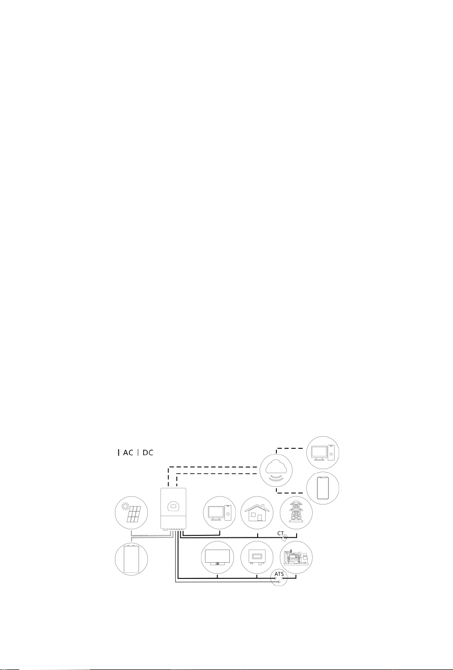
The following illustration shows basic application of this battery.
It also includes following devices to have a complete running system.
- Generator or Utility
- PV modules
- Low voltage Hybrid PCS (Charge & Discharge)
Consult with your system integrator for other possible system architectures depending on your
requirements.
8
2.3 Model Description
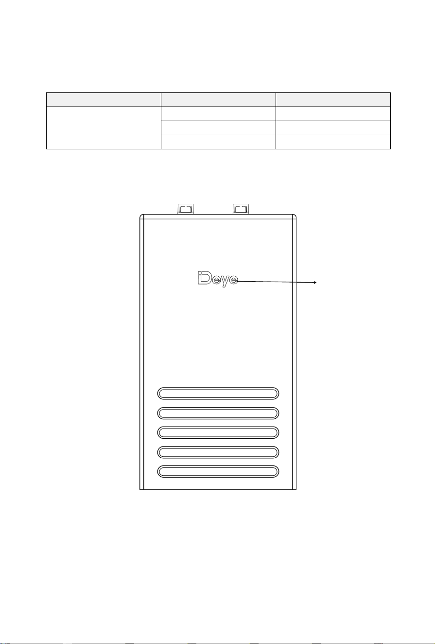
Your product is mainly divided into three categories due to different configurations, SE-F16-L,SE-F16-E
and SE-F16-C. This section will focus on the differences among these three versions.
Model Version Configuration
SE-F16
SE-F16-L Deye Logo
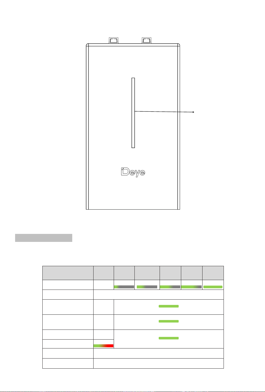
SE-F16-E LED indicator
SE-F16-C LCD screen
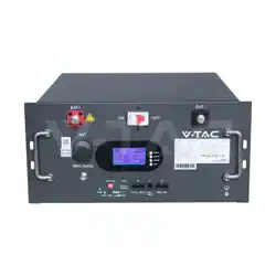
2.3.1 SE-F16-L
Deye Logo
9
2.3.2 SE-F16-E
LED indicator Instructions
Error : Red on the right and green on the left, long bright if equipment protected.
SOC : Battery capacity indicator, green light strip.
Condition Error
SOC
0%~20%
SOC
0%~40%
SOC
0%~60%
SOC
0%~80%
SOC
0%~100%
SOC
Power off off
Charge off
Show SOC & highest LED blink
Discharge or Idle off
Show SOC & long bright
Alarm off
Other LEDs are same as above.
System error/Protect
Upgrade Blink Fastly
Critical Error Blink Slowly
LED indicator
10
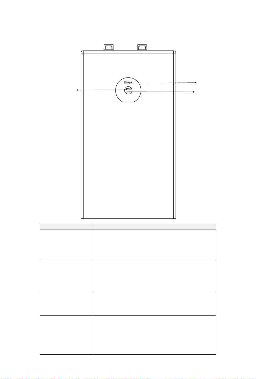
2.3.3 SE-F16-C
Condition Performance
Normal After initialized successfully, the LCD screen will be on
for long time and shows the SOC in percentage.
The screen stays on unless shutdown and dormancy.
The backlight in the shape of Deye appears blue.
Abnormal If the fault in the next table occurs, the corresponding
fault code will be displayed on the LCD screen. For
details, refer to the next table.The backlight in the
shape of Deye appears red.
Upgrade When upgrading, the screen will be filled with the
"upd" as well as the upgrade process in percentage.
The backlight in the shape of Deye appears blue.
Others 1. The Deye backlight displays red and flash quickly
when there is a communication failure between the
LCD screen and the BMS motherboard.
2. The Deye backlight displays red while the system is
upgrading with faults existing.
Status of Charge
(SOC)
Error Code
Backlight

11
Error Code Connotation Error Code Connotation
01 Cell over voltage 28 Mosfet short circuit
02 Cell under voltage 29 EEPROM error
04 Ultimate_Protection 30 Internal communication fails
05 Charge over current 31 PCS communication fails
06 Discharge over current 32 Master address repeat
07 Cell over temperature 45 Cur Limit Mos Adhesion
08 Cell under temperature 46 Mos Adhesion Susp
11 Cell voltage over difference 47 Heat Mos adhesion
12 Cell temperature over difference 48 Heat error
13 Mos over temperature 49 Over connect temp
14 Heating film over temperature 50 Pre charge fail
19 AFE-OCDL/OCD1/OCD2 51 Charge inverses
24 AFE-SCDL/SCD 52 Over terminal temp
25 AFE communication fails 53 Fuse blown
26 Cell voltage sampling fails 54 VOLT_OPEN_WIRE_FAIL
27 Temperature sampling fails 55 TEMP_OPEN_WIRE_FAIL
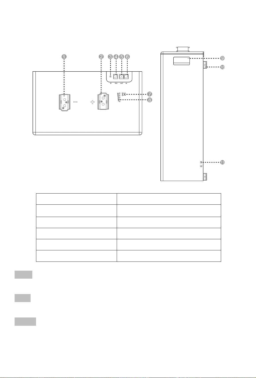
12
2.4 Product Overview
1. P- port 7. Status indicators
2. P+ port 8. SOC indicators
3. Battery switch 9. Handle
4. PCS port 10. Bracket mount
5. OUT port 11. Protective earth
6. IN port
P+ port
Positive output terminal.
P- port
Negative output terminal.
PCS port
Inverter communication terminal, to follow the CAN protocol (baud rate:500kbps),and RS485(baud
rate:9600bps), used
t
o output battery information to the inverter.
13
OUT port
Communication output terminal(RJ45port), to connect the "IN" terminal of next battery for
communication between multiple parallel batteries.
IN port
Communication input terminal(RJ45port), to connect the "OUT" terminal of previous battery for
communication between multiple parallel batteries.
Battery switch
To power on /off the battery.
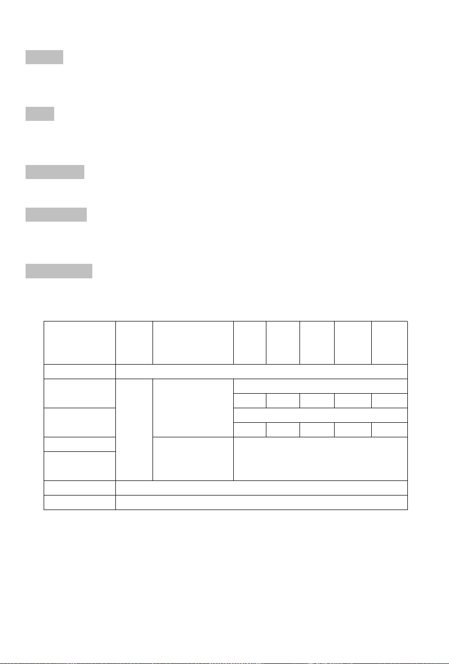
SOC indicators:
To display the state of remaining charge by 5 LED lights. Every LED indicates the SOC of 20%, 40%,
60%,80% and 100%.
Status indicators
RUN light: green LED lighting to show the battery running status.
Alarm light: yellow LED lighting to show the battery has been alarmed.
Condition RUN ALM SOC1 SOC2 SOC3 SOC4 SOC5
Power Off Off
Discharge or
Idle
Blink
Blink if Alarm
Exists
e.g., SOC67%
Off On On On On
Charge
e.g., SOC47%:
Off Off Blink On On
Alarm
Blink Same as 'Discharge or Idle'
System
Error/Protection
Upgrade Blink quickly
Critical Error Blink slowly
14
3 Preparation for Installation
After unpacking, check that packing contents are intact and complete , and free from any damage. If any
item listed in the Unpacking List is missing or damaged, contact your vendor.
3.1
Unpacking List
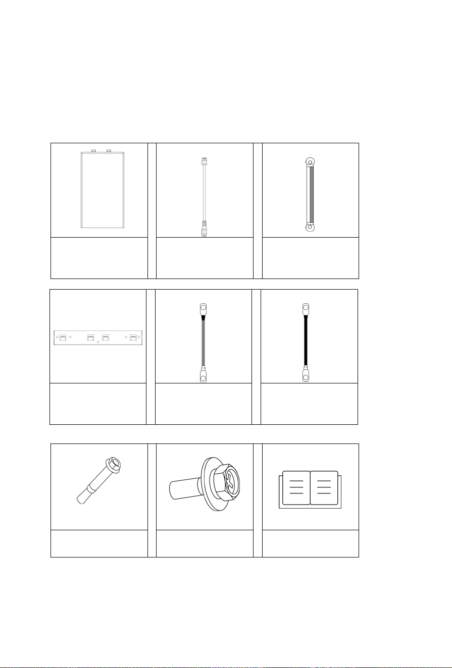
Battery pack*1pcs
26AWG 1000mm
communication cable
*1pcs
10AWG 1000mm
Ground wire*1pcs
Hook
*2pcs
1AWG 1000mm
Positive battery power
cable*1pcs
1AWG 1000mm
Negative battery
power cable*1pcs
Expansion bolt*9pcs
(M6*100)
Bolt*4pcs (M4*12) User manual*1pcs
15
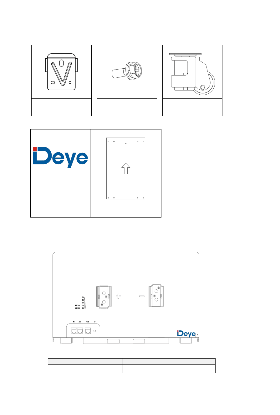
NOTE: Users may refer to the images below for guidance on applying the logo stickers.
Bracket *4pcs
Bolt*16pcs (M5*12,
provided with wheels)
Wheel*4pcs (Optional)
Logo sticker*1pcs
Positioning
paperboard*1
Item Distance
(
mm
)
A 10
16
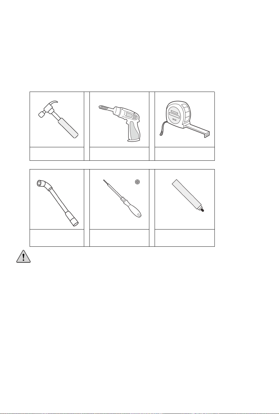
3.2 Required Tools
These tools are required to install the battery.
Note:
Use properly insulated tools to prevent accident tale electric shock or short circuits.
If insulated tools are not available, cover the entire exposed metal surfaces of the available
tools, except their tips, with electrical tape.
Hammer Drill Tape measure
Hexagon socket
wrench
Phillips screwdriver Marker
17
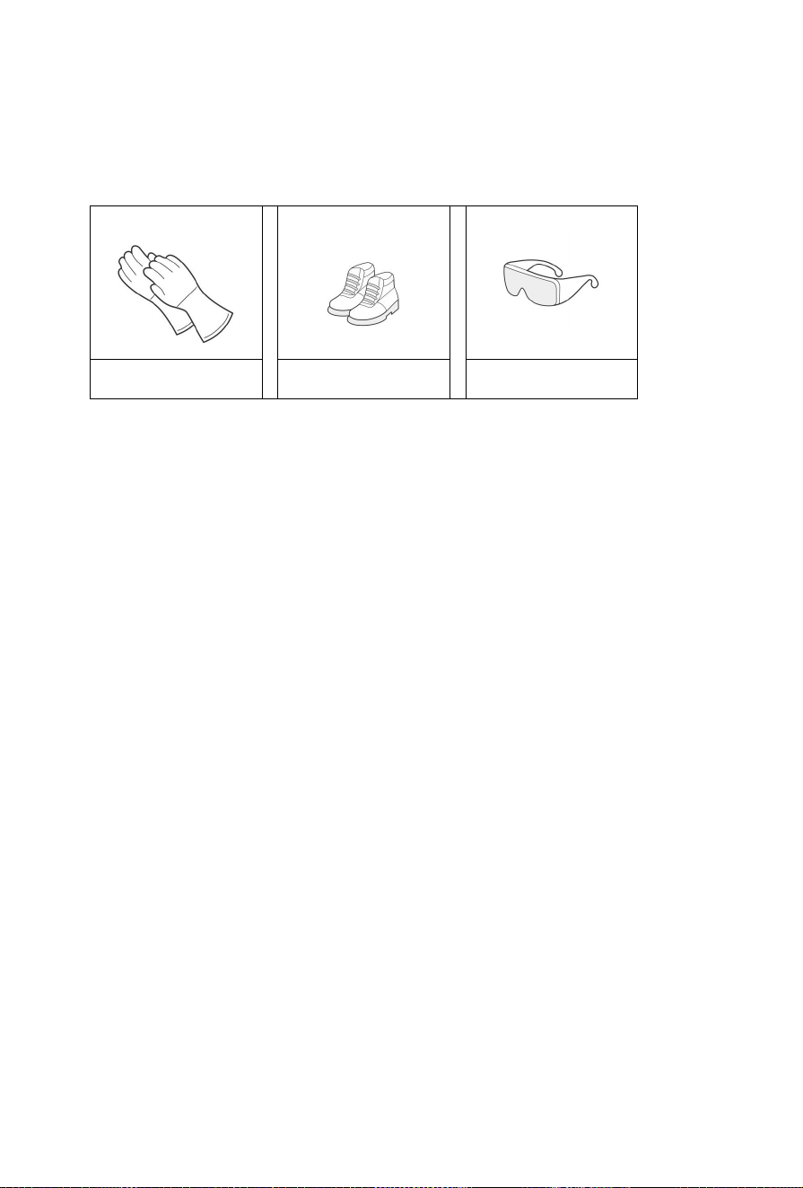
3.3 Safety Gear
It is recommended to wear the following safety gear when dealing with the battery pack.
Insulated gloves Safety shoes Safety goggles

18
4 Installation Instructions
4.1 Installation Personnel
• Only qualified professionals or trained personnel are allowed to install the equipment.
-Professionals:personnel who are familiar with the working principles and structure of the equipment,
trained or experienced in equipment operations and are clear of the sources and degree of various
potential hazards in equipment installation.
-Trained personnel:personnel who are trained in technology and safety have required experience,are
aware of possible hazards on themselves in certain operations and are able to take protective measures
to minimize the hazards on themselves and other people.
• Personnel who plan to install the equipment must receive all necessary safety precautions and local
relevant standards.
•Only qualified professionals are allowed to remove safety facilities and inspect the equipment.
•Knowledge of electronic, electrical wiring and mechanical expertise, and be familiar with electrical and
mechanical schematics.
• Understanding and complying with this document and other applicable documents.
19
4.2 Installation Environment
Danger!
Do not expose the equipment to flammable or explosive gas or smoke. Do not perform any
operation on the equipment in such environments.
Danger!
Do not store any flammable or explosive materials in equipment area.Do not cover or wrap the
battery.
Danger!
Do not place the equipment near heat sources or fire sources, such as smoke, candles, heaters, or
other heating devices. Overheat may damage the equipment or cause a fire.
Warning!
Install the equipment in an area far away liquids. Do not install it under areas prone to condensation,
such as under water pipe and air exhaust vent, or area prone to water leakage, such as air
conditioner vents, ventilation vents, or feeder windows of the equipment room. Ensure that no
liquid enters the equipment to prevent faults or short circuits.
Warning!
To prevent damage or fire due to high temperature, ensure that the ventilation vents or heat
dissipation systems are not obstructed or covered by other objects while the equipment is running.

20
• The installation and usage environment must meet relevant international,the local laws and
regulations.The user is obliged to protect the equipment against fire or other hazards.
• Keep the equipment out of the reach of children and away from daily working or living area,
including but not limited to the following areas:studio, bedroom, lounge, living room, music room,
kitchen,game room, room theater, sunroom,toilet,bathroom,laundry,and attic.
• Do not install the equipment in places that are enclosed, poorly-ventilated without proper fire
fighting facilities, or difficult for firefighters to access.
• Do not install the equipment in an easily accessible position because the temperature of the
enclosure and heat sink is high when the equipment is running.
• Do not install the equipment on a moving object, such as ship, train, or car.
• Ensure that the equipment is installed in a clean, dry and well ventilated area with proper
temperature, humidity and altitude range.Check for more data in the “Technical Specifications”
section.
• Do not install the equipment in an environment with magnetic dust, volatile or corrosive gases,
infrared and other radiations, organic solvents, conductive metal,or salty air.
• Do not install the equipment in an area conducive to growth of microorganism such as fungus or
mildew.
• Do not install the equipment in an area with strong vibration, noise, or electromagnetic
interference.
• Do not install the equipment in an position that may be submerged in water.
• Keep away from the air outlet of PCS to prevent personal injury..
• The floor and walls are completely water proof.
• The wall and floor is flat and level.
• Before installing and powering up the system, dust and iron filings must be removed to keep the
environment clean. The system cannot be installed in desert areas without a shell to protect against
sand.
•The equipment is designed for indoor use. Please avoid direct sunlight, rain exposure, snow laying
up during installation and operation.
21
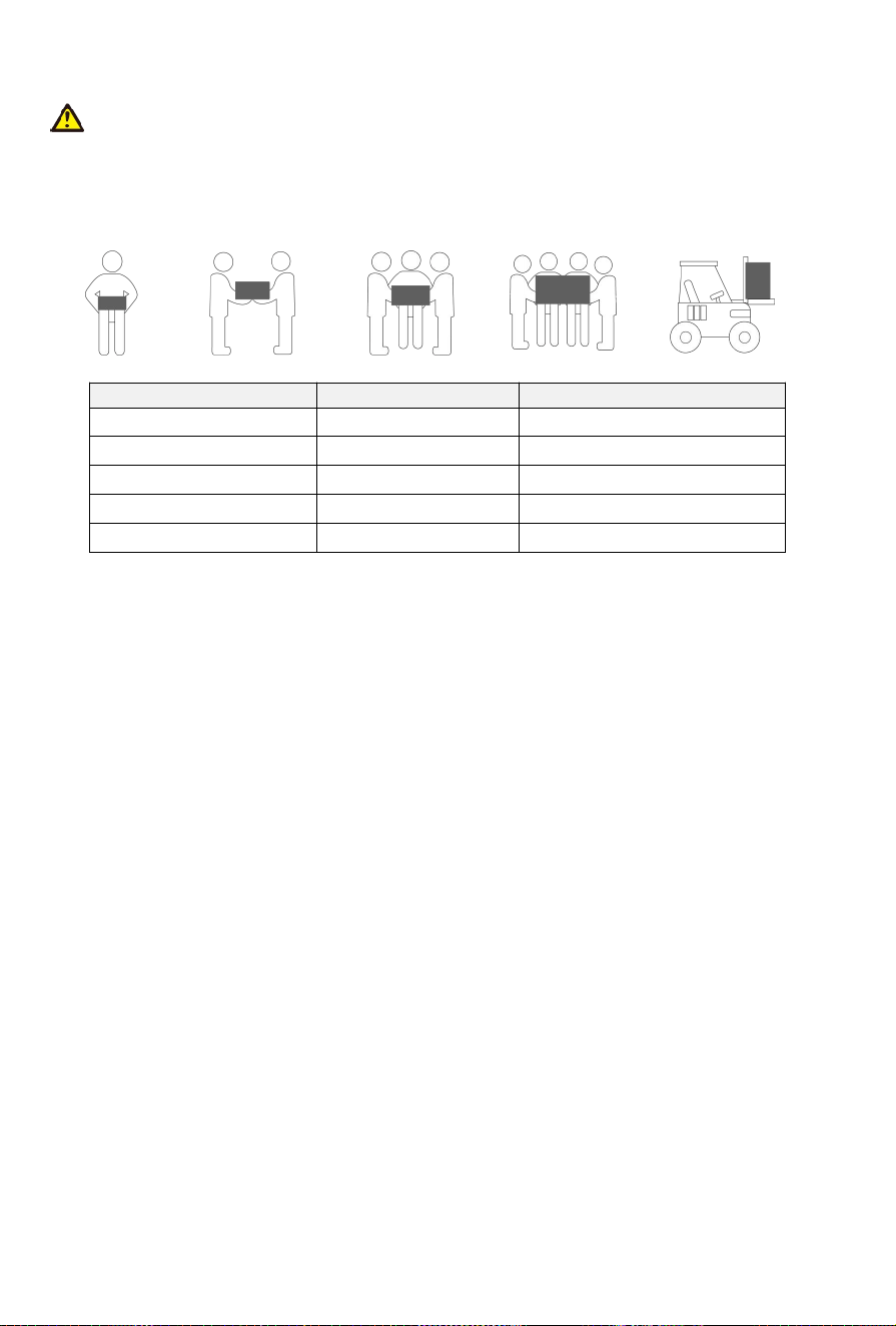
Caution!
Moving heavy objects.
Be careful to prevent injury when moving heavy objects. Select an suitable way to moving heavy
objects according to product weight.
Weight Method Recommendation
<18 kg (40lbs) Manual handling 1 person
18~32 kg (40~70lbs) Manual handling 2 persons
32~55 kg (40~70lbs) Manual handling 3 persons
55~68 kg (121~150lbs) Manual handling 4 persons
> 68 kg (150lbs) Moving device Forklift
22
4.3 Selection of Installation Sites
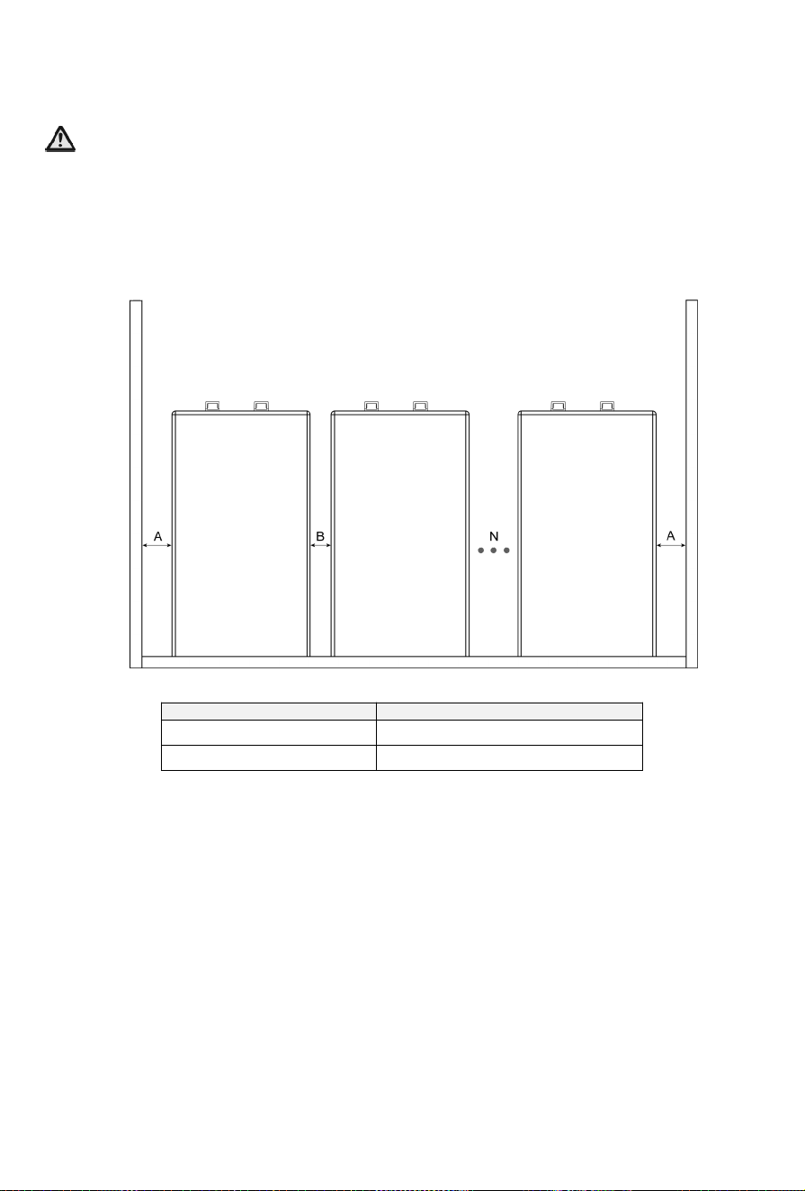
Caution!
Batteries should be installed in a clean flat place with no direct sunlight, away from water and fire sources,
and at a suitable temperature. The installation location is recommended to meet the size requirements of
the figure below:(0≤N≤29)
NOTE: This requirement only applies to floor-mounted installation.
Item Distance (mm)
A 200
B 100
23
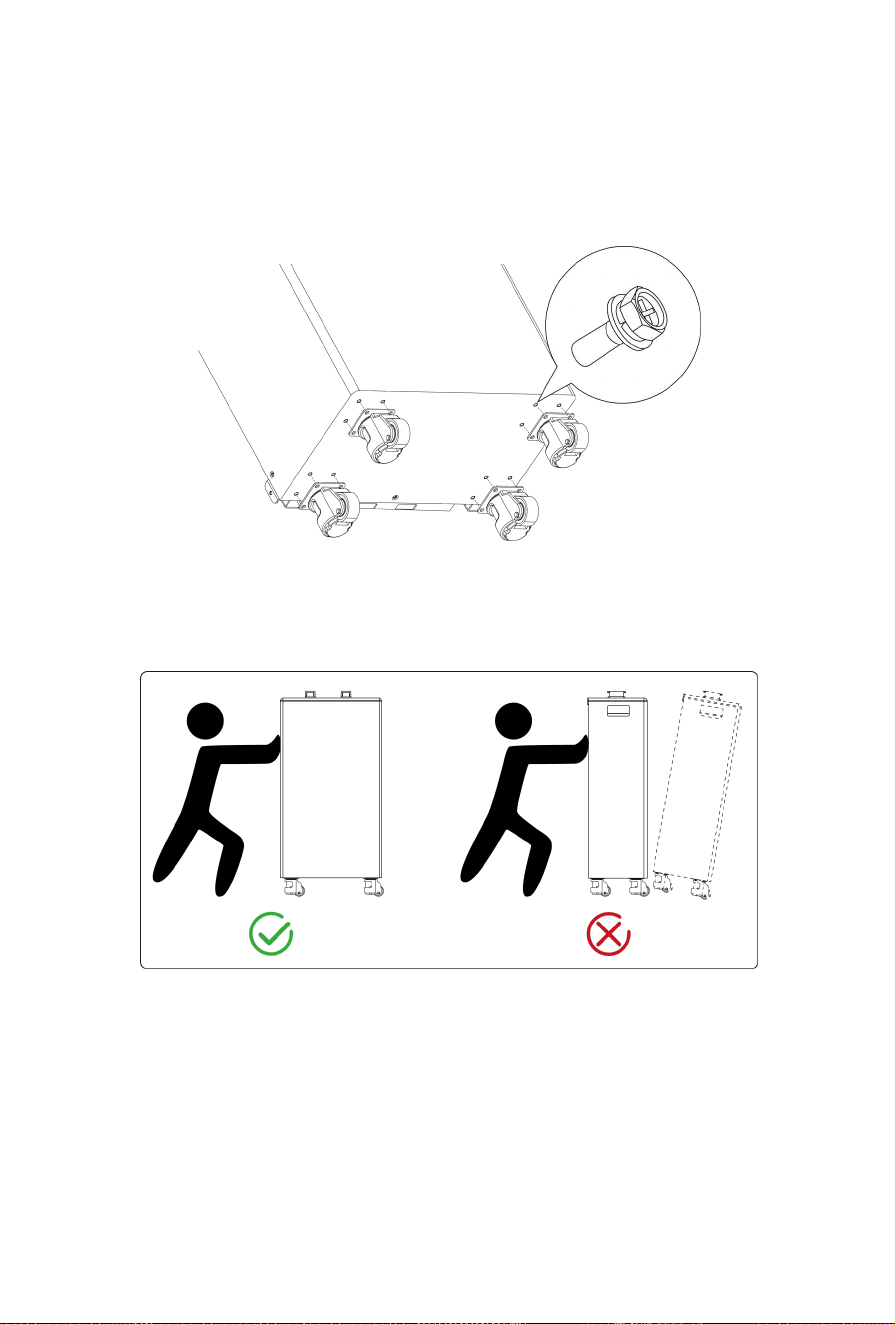
4.5 Mounting the Wheels (Optional)
Align four wheels with assembly holes located at the bottom of your battery, and then secure these
wheels to main body with 16 bolts (M5*12).
NOTE: Push your device with wheels in accordance with the picture below.
24
4.6 Installing the Battery
4.6.1 Wall-mounted/
Floor-mounted
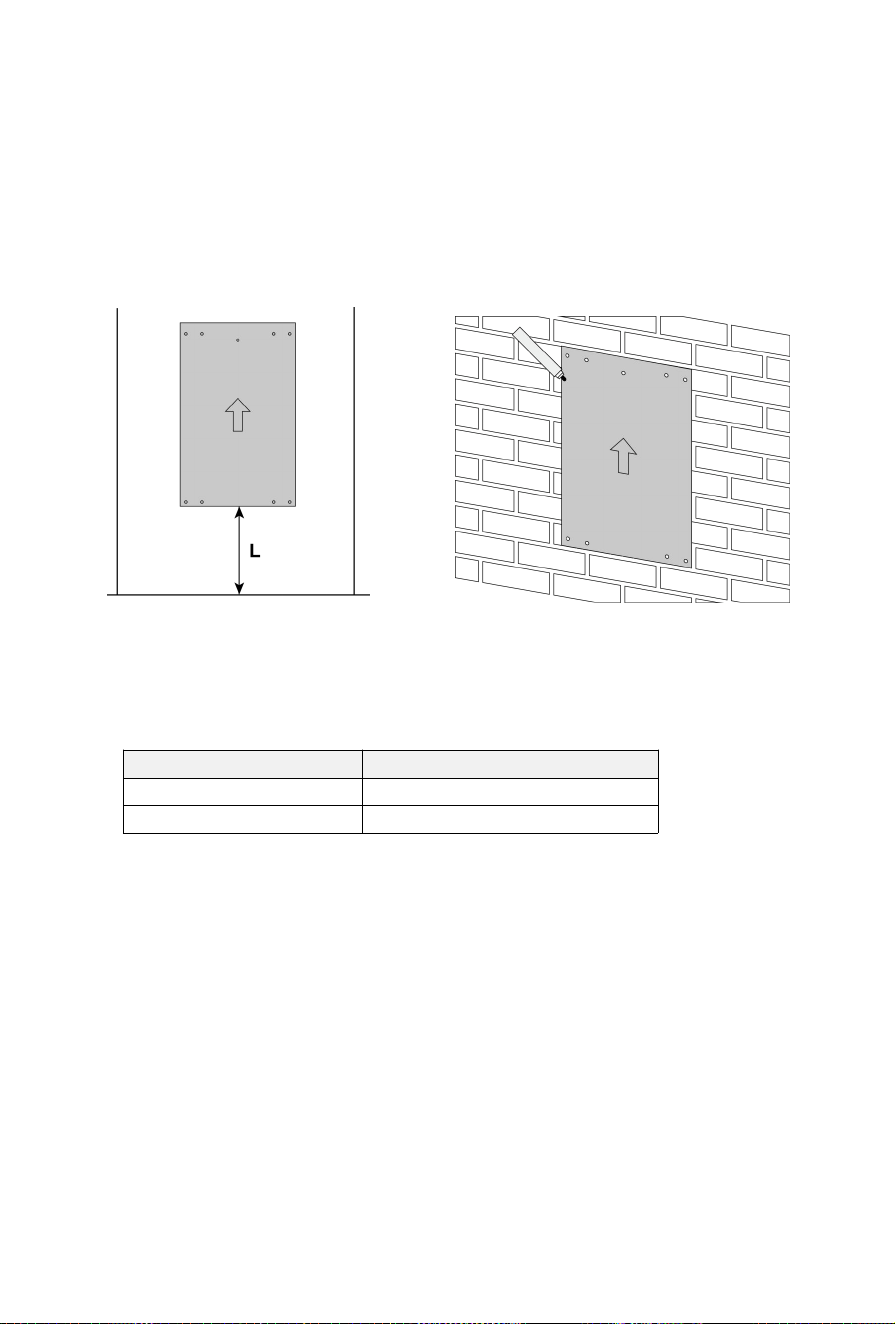
1) Choose and mark appropriate locations on the wall for drilling holes with a positioning cardboard. It is
noted that when carrying out the floor installation, only positions of five holes at the top of the
positioning paperboard need to be marked.
How to differ the floor-mounted installation from the wall-mounted installation mainly depends on the
clearance L between the ground and the positioning cardboard.
Installation mode Clearance (mm)
Wall-mounted L ≥300
Floor-mounted L=0
Ground
Wall
Wall
25
For
Wall-mounted:
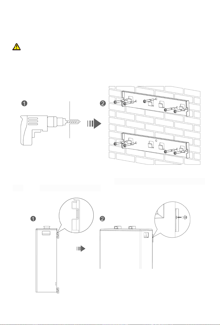
2) Drill 9 holes on the wall,with a diameter of 8 mm and depth of 100~110mm.
Note!
* When drilling holes, pay attention to prevent dust from entering the battery, which may affect the
battery performance and function.
* After drilling, never forget to clean up the floor.
3) Fix 2 hooks onto the wall with 9 expansion bolts (M6*100).
4) Carry the battery and hang it onto the hooks, making sure all bracket mounts on the back of the
battery are securely fastened to the hooks on the wall. It is recommended to only lock the two upper
bolts (M4*12) on both sides of the main body.
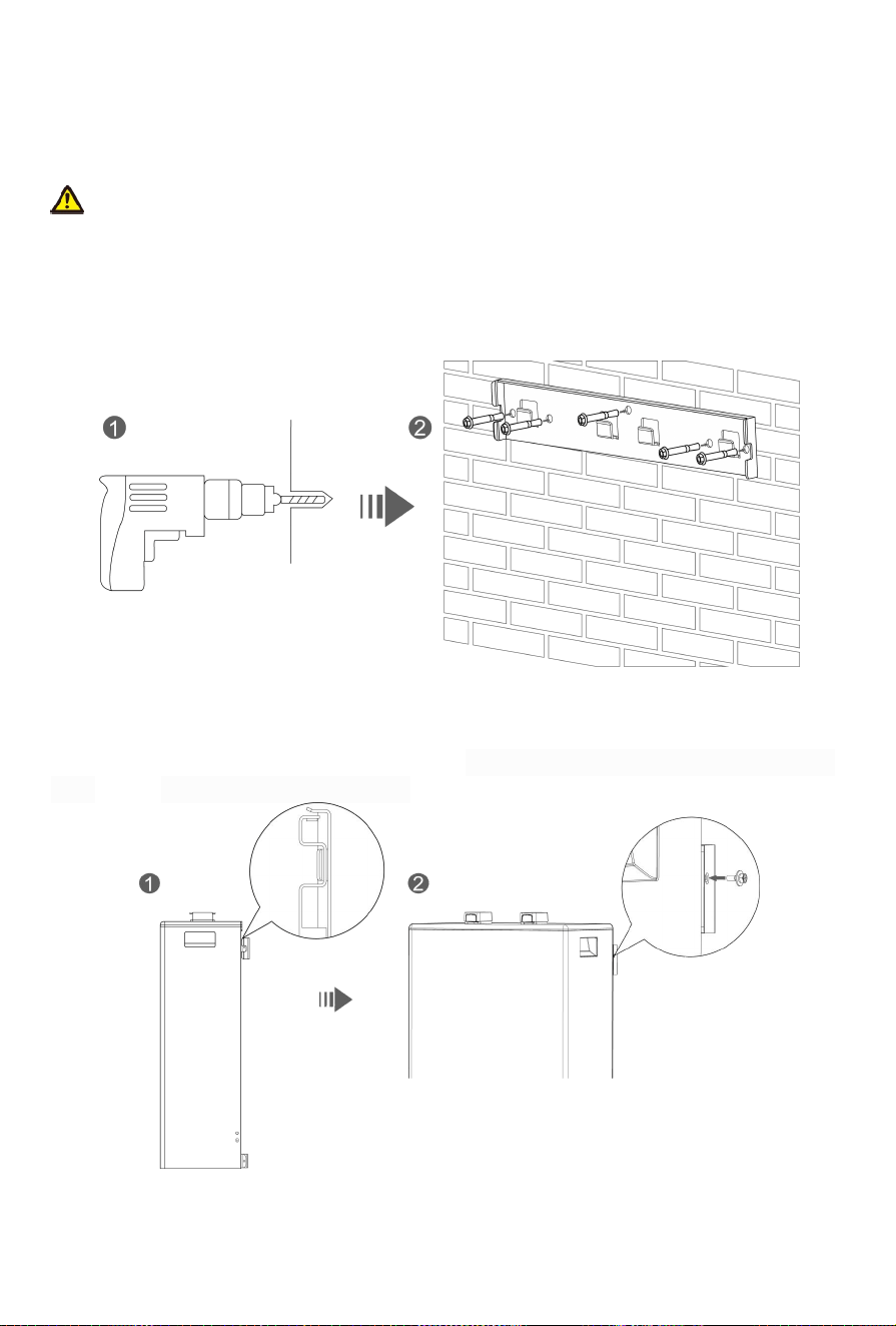
26
For Floor-mounted:
2) Drill 5 holes on the wall,with a diameter of 8 mm and depth of 100~110mm.
Note!
* When drilling holes, pay attention to prevent dust from entering the battery, which may affect the
battery performance and function.
* After drilling, never forget to clean up the floor.
3) Fix 1 hooks onto the wall with 5 expansion bolts (M6*100).
4)Carry the battery and hang it onto the hooks, making sure all bracket mounts on the back of the
battery are securely fastened to the hooks on the wall. It is recommended to only lock the two upper
bolts (M4*12) on both sides of the main body.
27
4.6.2 Stack-mounted
1)
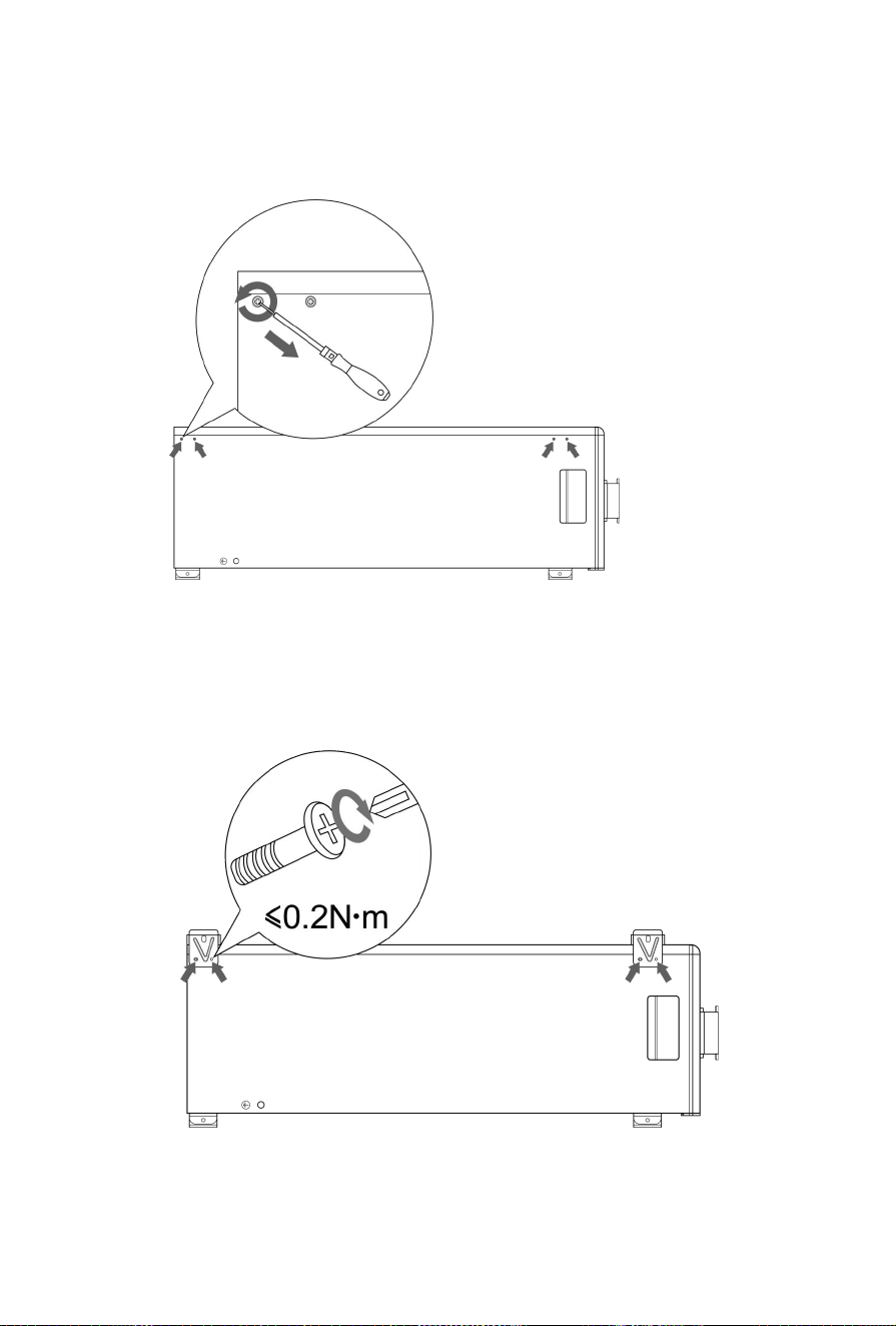
1)Remove 8 bolts (M3*10) on every battery that preset at the factory for future use.
2)
3)
4)
2)Secure 4 brackets to two sides of every battery with 8 bolts (M3*10) mentioned in the step 1.
28
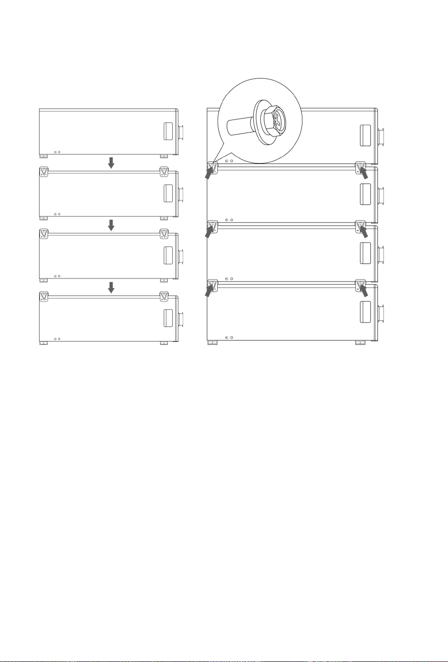
3) Stack the battery one by one and then secure them with 4 bolts
(M4*12)
.
The number of stacked
batteries can not exceed 4.
29
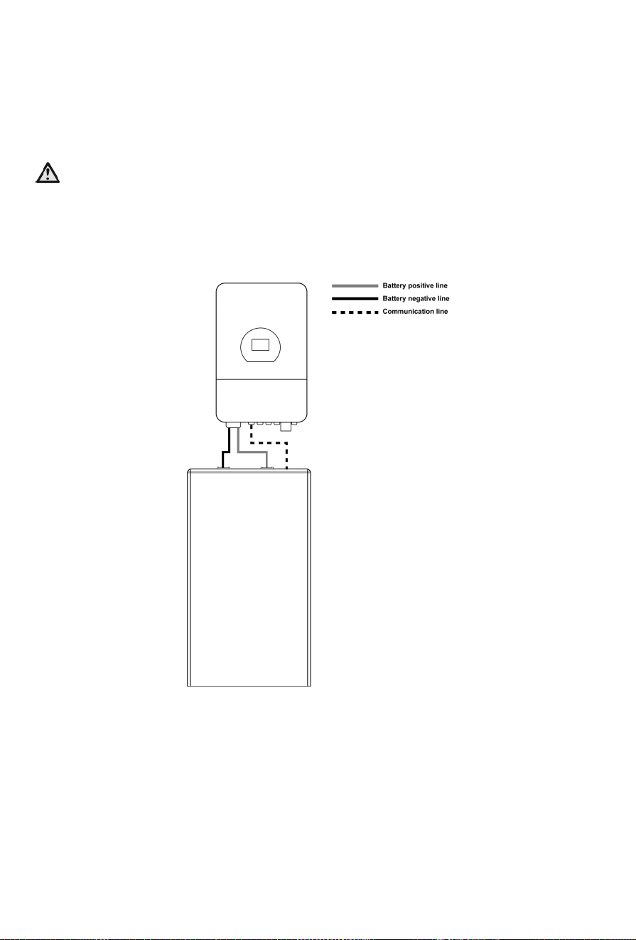
5. Electrical Connection
5.1 System Connection Precautions
Note!
This battery must be used in conjunction with compatible hybrid inverter models. It needs to establish
communication with the inverter to activate the lithium battery mode, ensuring optimal battery
performance.If used with an unmatched inverter, ensure that the maximum operating current does not
exceed 160A for charging and 180A for discharging at an ambient temperature of 25±2°C.
When connecting to inverters or being in parallel mode, please use cables provided in the unpacking list.
If other cables must be used in special cases, ensure they meet FCC standards.
5.2 Preparation before Wiring
Note!
It is noted to distinguish the positive and negative ends of cables.
Be careful to avoid misuse of lines used for communication between PCS and battery, battery and
battery.
Try to avoid cross-connection
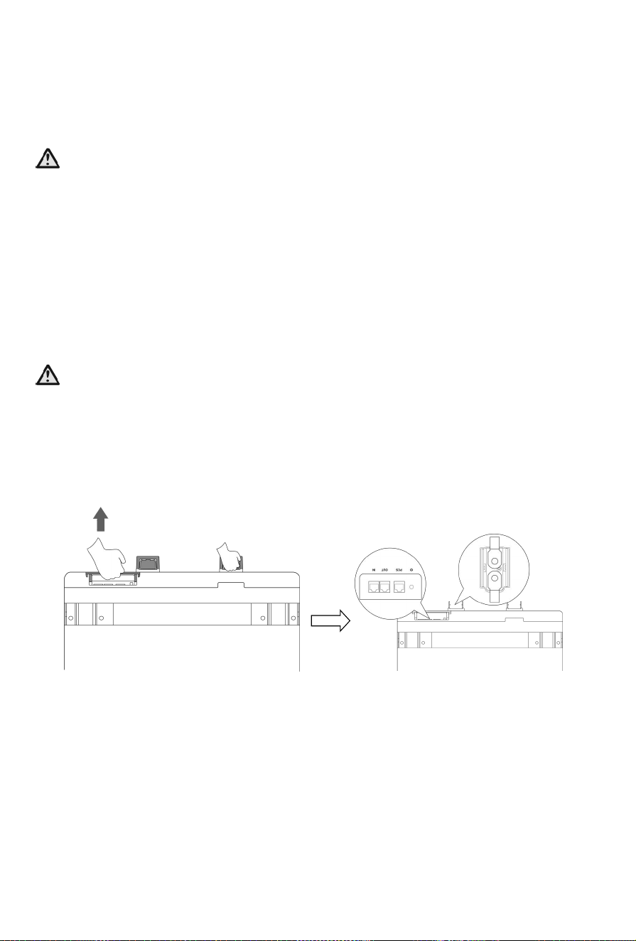
Before wiring, you need to remove the protective hood to carry out the wire connection.

30
Definition of IN
port pin
Definition of
OUT port pin
Definition of PCS
port pin
No. IN port pin No. OUT port
pin
No. PCS port pin
1 CANL 1 CANL 1 485-B
2 CANH 2 CANH 2 485-A
3 DI+ 3 DO+ 3 --
4 DI- 4 DO- 4 CANH
5 DI- 5 DO- 5 CANL
6 DI+ 6 DO+ 6 --
7 CANH 7 CANH 7 485-A
8 CANL 8 CANL 8 485-B
31
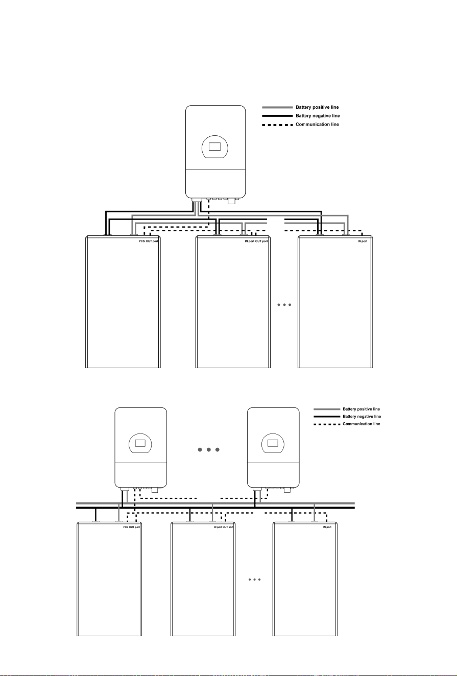
5.3 Parallel Mode 1
When batteries need to be used together in parallel, you can select different parallel modes to meet your
demands.
Caution!
It should be noted that the maximum current of single battery system is 230A. Exceeding 230A will
cause heating of the connectors and cable, and in severe cases, it will cause a fire accident. As for
cables, the recommended cross section of them should be at least 1AWG or 50mm².
32
Parallel Mode 2
Schematic diagram of connection of multiple batteries system:
Or
33
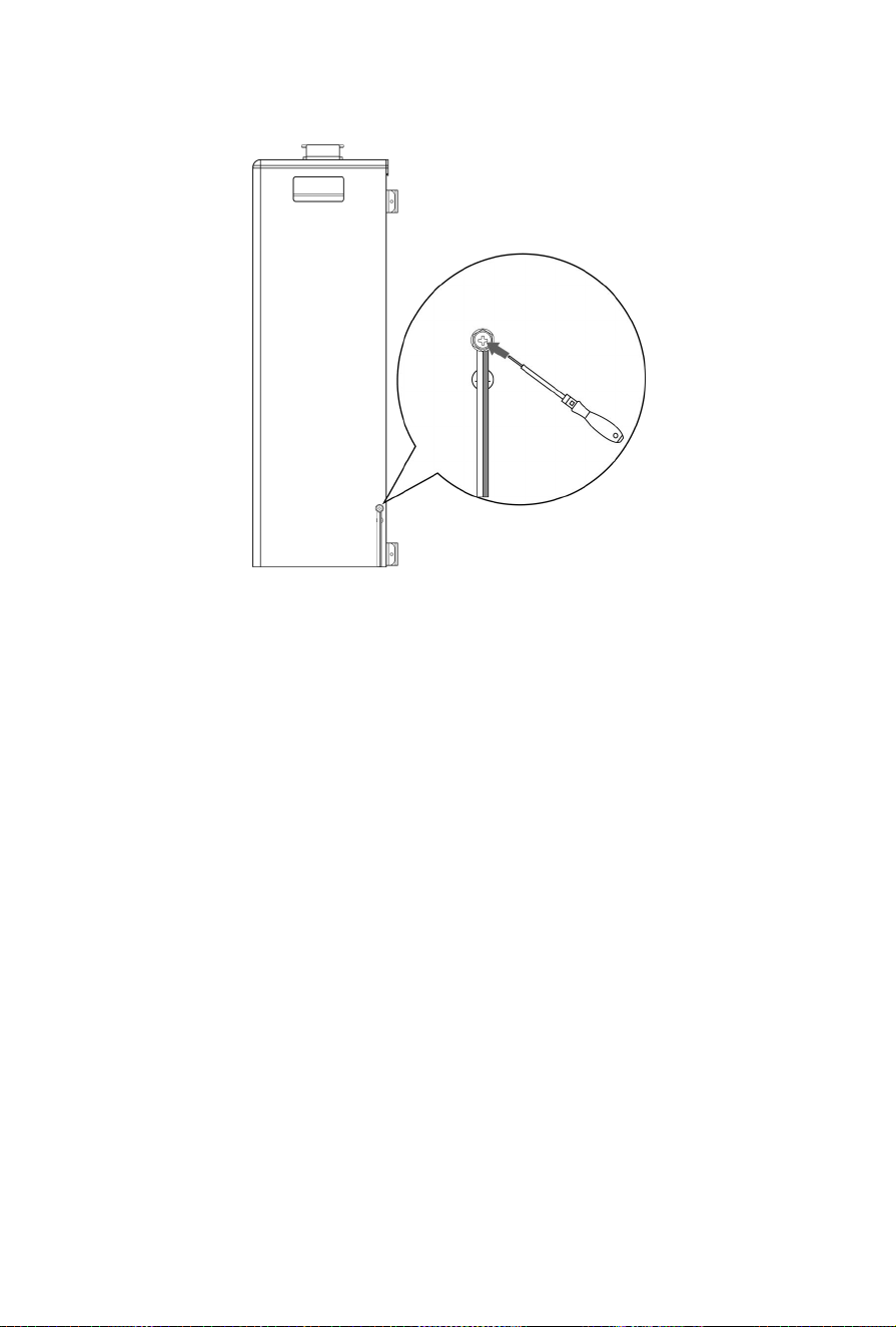
5.4 Grounding
Your battery system must be well grounded. Proceed as follows:
6 Power on/off the Product
6.1 Power on/off the Product
Before operating the product, ensure that:
•
All cables are wired correctly and firmly.
•
All fasteners including bolts and screws are tightened firmly.
•
No bystanders or animals enter into the working area.
•
Keep foreign objects , especially metal, away from the battery .
1. Press the battery switch to to turn on the equipment.
2. After you finish your work, press the battery switch to stop the equipment.

34
6.2 Buzzer
Your equipment is equipped with a buzzer, which will sound a alarm to reminder that you have to
check whether your equipment is in the following situations:
Condition Possible triggers Solutions
Alert for 100ms
at intervals of
2s with ALARM
LED flashing
SOC≤ 5%,not being charged Charge the battery in time
Alert once per
second with
the ALARM
LED flashing
simultaneously
Inverse connection when
charging
Check and and then rectify the wire
connection
There is MOS adhesion existing Contact the service center
Cell voltage is higher than 3.8V Check that sampling line is normal;
Test the cell voltage using a
multimeter;
Inspect the SOH of the battery;
Refer to data record for recharge at
the low current.
Discharge/charge temperature
is higher than the valve value.
Check that there is rapid charge at
the high current or there is a surge
on load ;
Check that there is long-time charge
or over-discharge ;
Check that the temperature of the
environment around the battery ;
Check that the battery is aged or
damaged
35
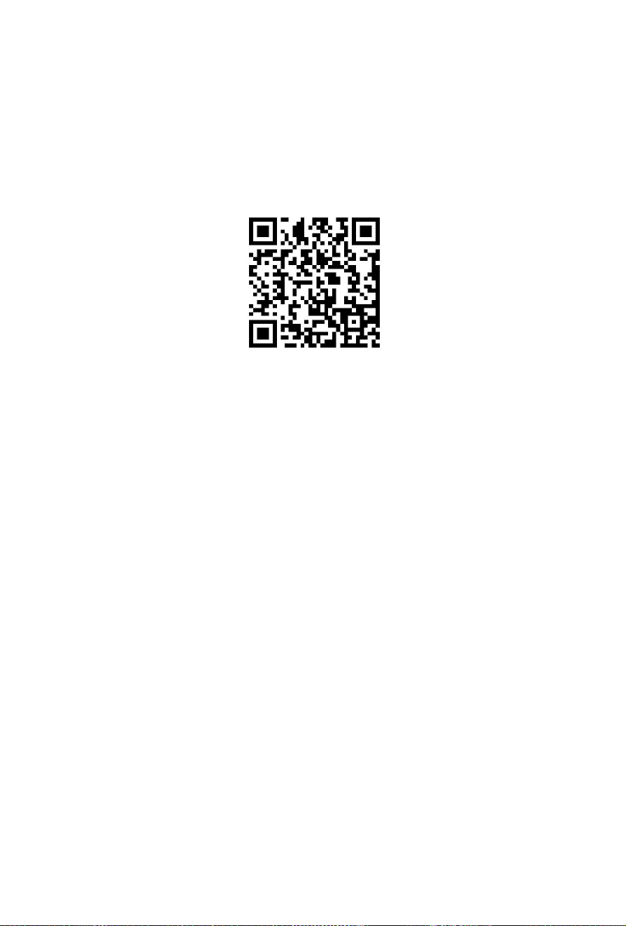
6.3 How to utilize your APP?
As you device is designed to possess Bluetooth function, it can connect to the Deye Cloud App via
Bluetooth. Following successful login and registration, users can retrieve information about battery
packs or the entire system. For detailed instructions on the Deye Cloud App, refer to the operation
manual by scanning the provided QR code.

36
7 Inspection, Cleaning and Maintenance
7.1 General Information
The battery product is not fully charged. It is recommended that the installation be completed within 3
months after arrival;
During the maintenance process, do not re-install the battery in the battery product. Otherwise, the
performance of the battery will be reduced;
It is forbidden to dismantle any battery in the battery product, and it is forbidden to dis- sect the
battery;
After the battery product is over-discharged, it is recommended to charge the battery within 48 hours.
The battery product can also be charged in parallel. After the battery product is connected in parallel, the
charger only needs to connect the output port of any product battery.
Never attempt to open or dismantle the battery! The inside of the battery does not contain serviceable
parts.
Disconnect the Li-Ion battery from all loads and charging devices before performing cleaning and
maintenance activities.
Place the enclosed protective caps over the terminals before cleaning and maintenance activities to
avoid the risk of contacting the terminals.
All the battery terminals must be disconnected for maintenance.
Please contact the supplier within 24 hours if there is something abnormal.
Do not use cleaning solvents to clean battery.
7.2 Inspection
Inspect for loose and/or damaged wiring and contacts, cracks, deformations, leakage, or damage of
any other kind. If damage to the battery is found, it must be replaced. Do not attempt to charge or use a
damaged battery. Do not touch the liquid from a ruptured battery.
Regularly check the battery’s state of charge. Lithium Iron Phosphate batteries will slowly self-
discharge when not in use or whilst in storage.
Consider replacing the battery with a new one if you note either of the following conditions:
-The battery run time drops below 70% of the original run time.
-The battery charge time increases significantly.
-
7.3 Cleaning
If necessary, clean the Li-Ion battery with a soft, dry cloth. Never use liquids, solvents, or abrasives to
clean the Li-Ion battery.
7.4 Maintenance
The Li-Ion battery is maintenance-free. Charge the battery to approximately > 80% of its capacity at least
once every year to preserve the battery capacity.

37
8 Storage
The battery product should be stored in a dry, cool, and cool environment;
If the battery is stored for long time, it is required to charge them every six months, and the SOC
should be no less than 50%.
Generally, the maximum storage period at room temperature is 6 months. When the battery is stored
over 6 months, it is recommended to check the battery voltage. If the volt age is higher than 51.2V, it
can continue to store the battery. In addition, it is needed to check the voltage at least once a month
until the voltage is lower than 51.2V. When the voltage of the battery is lower than 51.2V, it must to be
charged according to the charging strategy.
When the battery product is stored, the source of ignition or high temperature should be avoided and
it should be kept away from explosive and flammable areas.
If your batteries need to be charged or discharged in lead-acid mode,maintain a charge/discharge
current of 0.2C within a temperature range of 5°C to 45°C.

38
9 Troubleshooting
To determine the status of the battery system, users must use additional battery status monitoring
software to examine the protection mode. Refer to the installation manual about using the monitoring
software. Once the user knows the protection mode, refer to the following sections for solutions.
Fault Type Phenomenons Possible Causes Solutions
Information
collection fails
The cell voltage
sampling circuit is
faulty.
The cell temperature
sampling circuit is
faulty
The welding point for cell
voltage sampling is loose or
disconnected.
The voltage sampling terminal
is disconnected.
The cell temperature sensor
has failed.
Replace the
collection line.
Electrochemical
cell error
The voltage of the cell
is low or unbalanced.
Due to large self- discharge,
the cell over discharges to
below 2.0V after long term
storage.
The cell is damaged by external
factors, and short circuits,
pinpricks, or crushing occur.
Replace the
battery.
Over-voltage
protection fails
The cell voltage is
greater than 3.65 V in
charging state.
The battery voltage is
greater than 58.4 V.
The busbar input voltage
exceeds the normal value.
Cells are not consistent. The
capacity of some cells
deteriorates too fast or the
internal resistance of some
cells is too high.
If the battery
cannot be
recovered due to
protection against
abnormality
contact local
engineers to
rectify the fault.
Under voltage
protection fails
The battery voltage is
less than 44.8V.
The minimum cell
voltage is less than
2.8V
The mains power failure has
lasted for a long time.
Cells are not consistent. The
capacity of some cells
deteriorates too fast or the
internal resistance of some
cells is too high.
Same as above.
Charge or dis-
charge high
temperature
protection fails
The maximum cell
temperature is greater
than 60℃
The battery ambient
temperature is too high.
There are abnormal heat
sources around
Same as above.
Charge low
temperature
The minimum cell
temperature is less
The battery ambient
temperature is too low.
Same as above.

39
protection fails than 0℃
Discharge low
temperature
protection fails
The minimum cell
temperature is less
than -20℃
The battery ambient
temperature is too low.
Same as above.

40
10 Technical Specifications
Main Parameter SE-F16
Battery Chemistry LiFePO
4
Capacity (Ah) 314
Scalability
[1]
Max.32 pcs in parallel
Nominal Voltage (V) 51.2
Operating Voltage(V) 44.8~57.6
Nominal Energy (kWh) 16
Charge Current (A)
[2]
Max. Continuous 160
Peak 280 (10 sec)
Discharge Current (A)
[2]
Max. Continuous 230
Peak 280 (10 sec)
Other Parameter
Recommend Depth of Discharge 90% DoD
Dimension (W/H/D, mm) 400×708×233 (Without hanging board)
Weight Approximate 109kg
Master LED indicator LED(SOC, working, protecting) & Buzzer
IP Rating of enclosure IP21
Working Temperature
Charge: 0℃~55℃
Discharge: -20℃~55℃
Storage Temperature 0℃~35℃
Relative Humidity 95% (non-condensing)
Altitude ≤3000m
Cycle Life
≥6000(25℃±2℃,70%EOL)
Installation Wall-Mounted, Floor-Mounted,Stack-Mounted
Communication Port CAN2.0, RS485, Bluetooth, APP
Energy Throughput
[3]
25 MWH
Certification UN38.3, MSDS, CE, CB
[1] Max.64 pcs can parallel with CAN-Box.
[2] The current is affected by temperature and SOC. This max.continuous current is only supported in lithium mode; for
lead- acid mode, please refer to the manual for the max.continuous current.
[3] Conditions apply, refer to Deye Warranty Letter.
41
11 Environmental Disposal
Used batteries can not be disposed of as household waste. You are obliged to handle waste batteries,
such as removal of privacy on product, and return them to designated or authorized recovery point
according to applicable regulations and standards on waste battery disposal.
Attention:
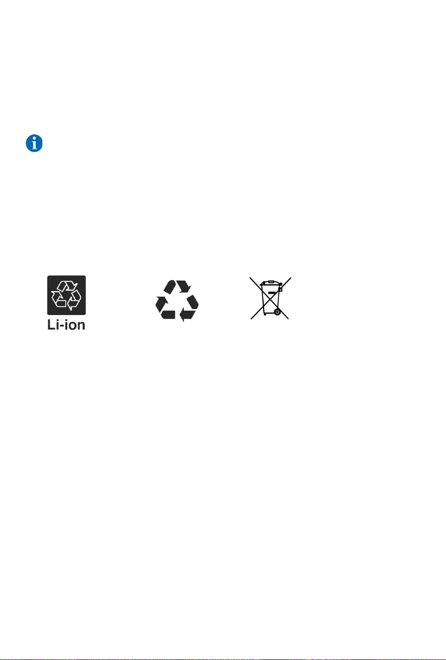
1. Do not dispose of batteries and rechargeable batteries as domestic waste!
You are legally obliged to return used batteries and rechargeable batteries.
2. Waste batteries may contain pollutants that can damage the environment or your health if improperly
stored or handled.
3. Batteries also contain iron, lithium and other important raw materials, which can be recycled.
For more information, please visit http://www.deyeess.com. Do not dispose of batteries as
household waste!

42
12 Transportation Requirements
1. The battery products should be transported after packaging and during the transportation process.
Severe vibration, impact, or extrusion should be prevented to prevent sun and rain. It can be transported
using vehicles such as cars, trains, and ships.
2. Always check all applicable local, national, and international regulations before transporting a Lithium
Iron Phosphate battery.
3. Transporting an end-of-life, damaged, or recalled battery may, in certain cases, be specially limited or
prohibited.
4. The transport of the Li-Ion battery falls under hazard class UN3480, class 9. For transport over water,
air and land, the battery falls within packaging group PI965 Section I. Use Class 9 Miscellaneous
Dangerous Goods and UN Identification labels for transportation of lithium-ion batteries which are
assigned Class 9. Refer to relevant transportation documents.
Class 9 Miscellaneous Dangerous Goods and UN Identification Label