
Thank you very much for purchasing this Air Source Heat Pump. Please
read this use and installation instructions carefully before installing and
using this appliance and keep this manual for future reference.
Packing List
Accessory
Qty
Purpose
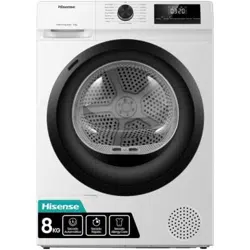
TPR Valve
1PC
1PC
1PC
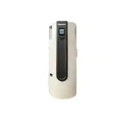
Hose Clamp
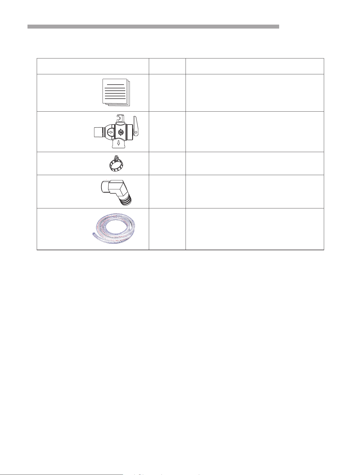
Drainage Nozzle
Drain-pipe
2PC For joint socket connection
Discharge condensate water
Installation operation guide
Discharge condensate water
Protect the the unit system
Operation Instruction
Φ19×1.3m
Safety Precautions
General Information
2
4
Part Names
8
Installation of Heat Pump
9
Pipe Line Connection
12
Electrical Connections
14
Method of Application
16
Instruction of operation
17
Operation Parameter Query
20
Operation Instruction
21
Trouble Shooting
24
Pilot run of Heat Pump
25
Maintenance and Solution
26
After-sale Service
34
1
2
Please make sure you have read safety precautions shown in the manual. This part provides quite
important safe points for you and please operate it based on safety precautions.
1. Household electrical system must have a reliable ground connection.
2. Household electrical system must have a leakage protection device
3. Do not dismantle any permanent instruction, label or parameter plate attached to the outside
cover or any internal plate of heat pump
4. Please ensure a dealer or professional person installs the device; Installer must have professional
knowledge, any improper operation may cause fire, electric shock, injury or leakage etc.
5. Please obey the local electrical regulations to connect power supply
6. When you need to remove or re-install heat pump, please ensure this is done by a professional
licensed person
7. Any self-transformation or repair is forbidden, improper repair may cause fire, electric shock, injury
or leakage etc. must entrust professional licensed person to repair
8. Earthing pole of power outlet must have a reliable connection, and rated current value should be
not less than 20A. Outlet and power plug must be kept dry to prevent leakage, outlet and power plug
must be well matched.
9. Due to possibility of water spatter, the installation height of power plug must be no less than 1.8m.
Ensure power plug is installed away from water source. Ensure children can not touch power plug.
10. One way valve suitable to application must be installed near to cold water outlet
11. In the state of energization and heating.
12. For continued safety of this appliance it must be installed, operated and maintained in
accordance with the manufacturer’s instructions
13. This appliance may deliver water at high temperature. For Australian installations, refer to the
plumbing code of Australia(PCA), local requirements and installation instructions to determine if
additional delivery temperature is required
14. Australian installation shall conform to the Plumbing Code of Australia (PCA)
15. If the fixed appliance is not fitted with a power cord and plug, or is not fitted with other devices to
disconnect the power cord (these devices must have contact separation at all poles and can be
completely disconnected under overvoltage Class III conditions; All-pole disconnect switch), then the
disconnect device must be incorporated into the fixed wiring according to the arrangement of wiring
rules
.
.
.
.
.
.
.
.
.
.
.
Safety Precautions
WARNING
This unit is required reliable
earthing before usage,
otherwise might cause
death or injury
3
16. This product must be installed outside only.
17. Do not use means to accelerate the defrosting process or to clean, other than those
recommended by the manufacturer
18. The appliance shall be stored in a room without continuously operating ignition sources (for
example: open flames, an operating gas appliance or an operating electric heater)
19. Do not pierce or burn
20. Be aware that refrigerants may be odorless
21. Maintenance should only be carried out as recommended by the supplier
22. Ducts connected to electrical appliances must not contain ignition sources
23. Appliances should be stored in a well-ventilated area with the room size corresponding to the
designated operating room area
24. The appliance shall be stored so as to prevent mechanical damage from occurring.
25. This appliance is not intended for use by persons (including children) with reduced physical,
sensory or mental capabilities or lack of experience and knowledge unless they have been given
supervision or instruction concerning use of the appliance by a person responsible for their safety.
26. Children should be supervised to ensure that they do not play with the appliance.
27. If the power cord is damaged; it must be replaced by the manufacturer, its service agent or a
similarly qualified person in order to avoid a hazard.
28. If the hot water system is not used for two weeks or more, a quantity of highly flammable
hydrogen gas may accumulate in the water heater. To dissipate this gas safely, it is recommended
that a hot tap be turned on for several minutes or until discharge of gas ceases. Use a sink, basin, or
bath outlet, but not a dishwasher, clothes washer, or other appliance. During this procedure, there
must be no smoking, open flame, or any electrical appliance operating nearby. If hydrogen is
discharged through the tap, it will probably make an unusual sound as with air escaping.
.
.
.
.
.
.
.
Safety Precautions
General Information
4
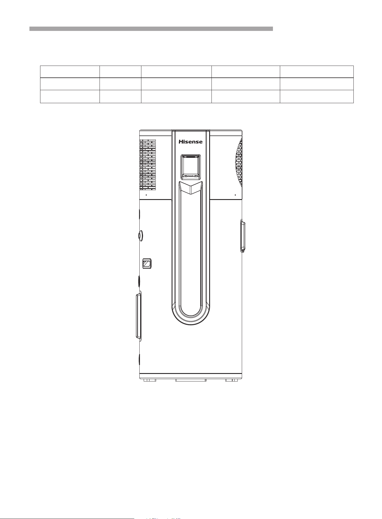
Model Weight(kg) Dimension(D×H,mm) Power supply Water connection size
AHS-210HF4GHB 120 Φ620×1518 220V/ 50Hz/ 1 phase 3/4”
AHS-270HF4GHB 140 Φ620×1838 220V/ 50Hz/ 1 phase 3/4”
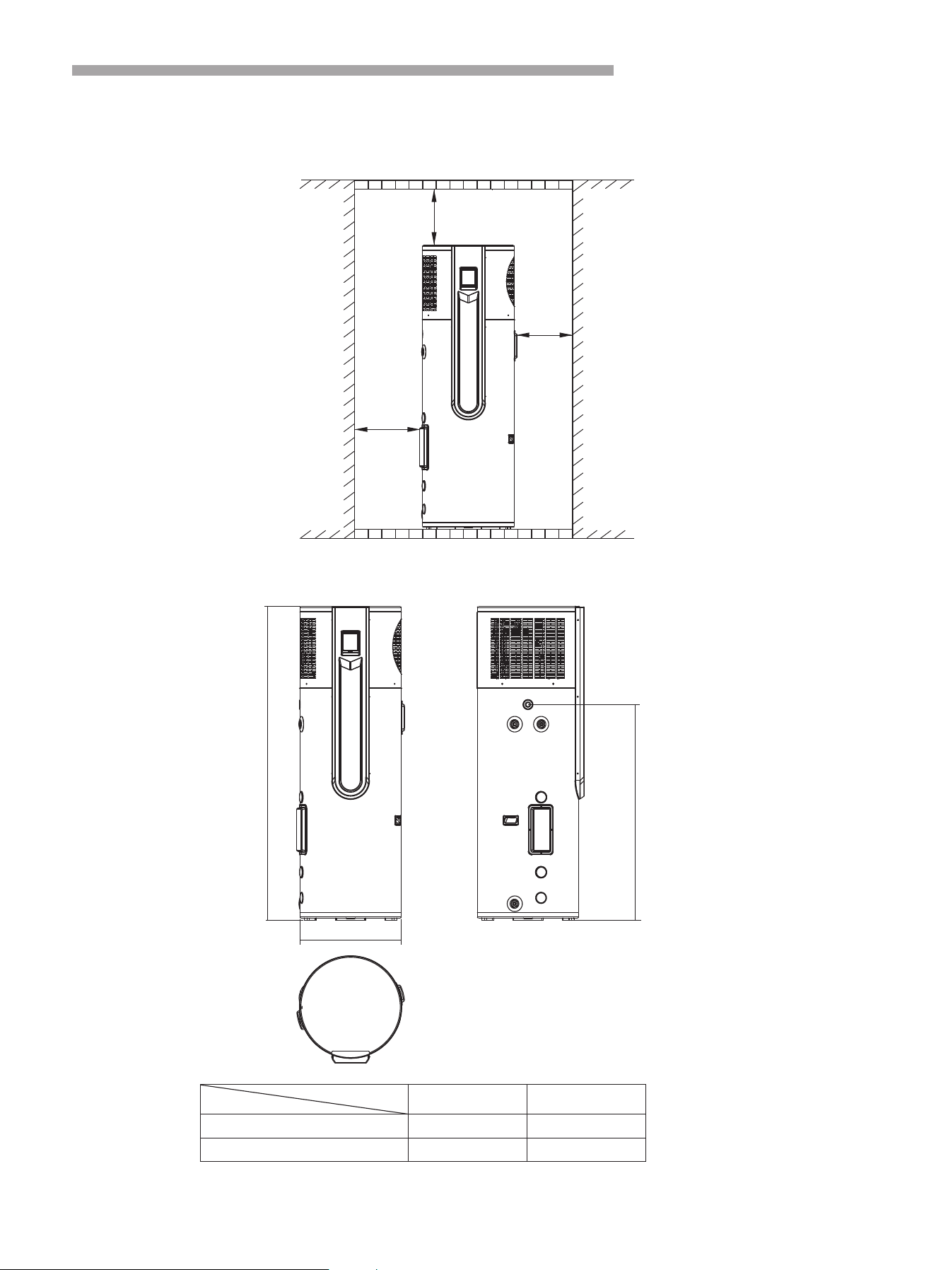
1. Measurement
2. External appearance
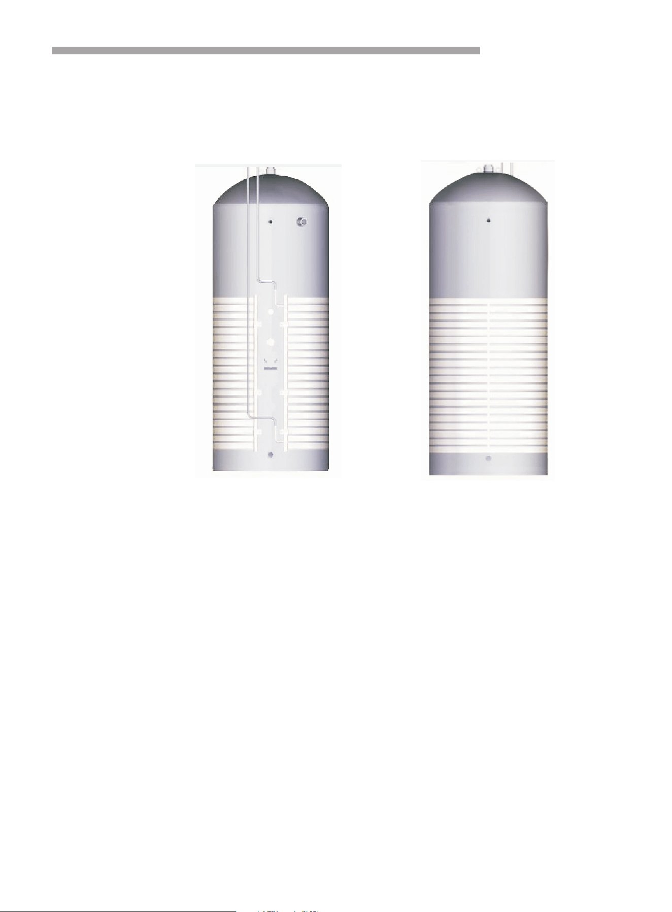
General Information
5
3. Features
All in one heat pump for sanitary hot water :
3.1 Has complete isolation between water and electricity, without electric shock possibilities.
3.2 No fuel tubes and storage, no potential danger from oil leakage, fire, explosion, etc..
3.3 No cross contamination potential, the condenser coil is an external coil wrapped around the stainless
tank, it does not come in contact with water directly.
3.4 The maximum outlet water temperature is 75ºC. The system ensures the water is heated stably and
quickly with innovative heating methods combining electric heating and heat pump heating.
3.5 Automatic start-up and shutdown, automatic defrosting by revising refrigerant cycle.
3.6 According to heat pump principles, the unit absorbs heat from outdoor air and transfers heat to water with
a thermal efficiency of approximately 4.17 (Under the condition A20/15ºC W15/55 ºC).
3.7 The unit will operate within the temperature range from -7 ºC to 43 ºC. The unit is not affected by night,
cloudy sky, rain or snowy weather.
General Information
6
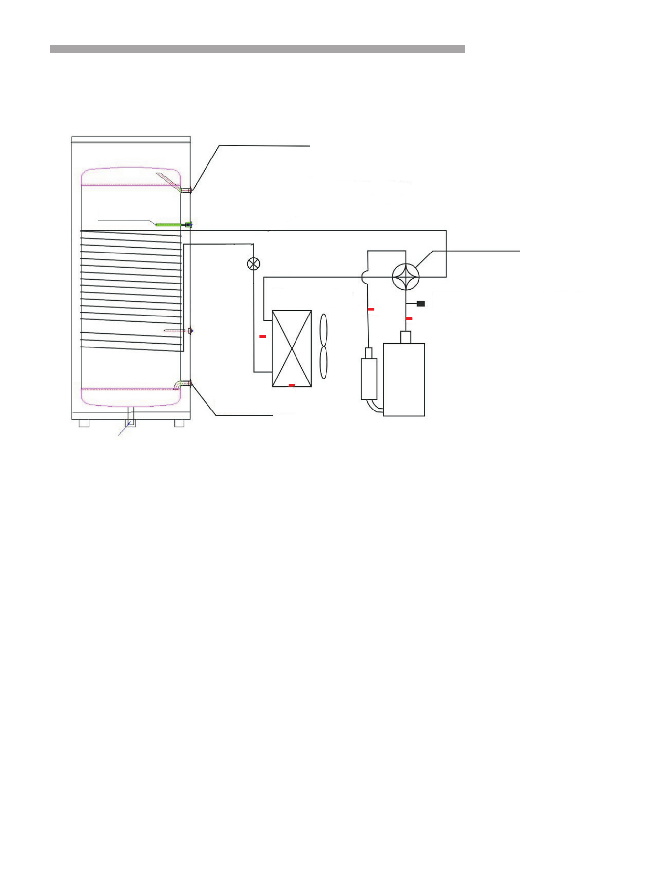
T4
T1
T2
Hot water outlet
4-way valve
Water inlet
Compressor
Evaporator
EEV
EH
Anode rod
High pressure switch
4. Refrigerant circuit
Compressor:Rotary, R290.
Evaporator: Copper tube and aluminum fin type heat ex-changer.
EXV: Electronic expansion valve, the opening is regulated according to the discharge air temperature of
compressor.
Fan: Centrifugal fan with three speeds.
High Pressure Switch: When the discharge pressure of compressor is 3.0MPa or higher, protection switch will
be triggered, then if the discharge pressure is below 2.4MPa, the protection switch will disengage.
T3

General Information
7
5. Specifications
Model AHS-210HF4GHB AHS-270HF4GHB
Power supply 220V~240V/50HZ 220V~240V/50HZ
Rated Input Power(Heat pump) (kW) 1.2 1.2
Rated Input Current(Heat pump) (A) 5.3 5.3
Rated Heating Capacity(Heat pump) (kW) 2.78 2.78
Rated Input Power(Resistance) (kW) 1.8 1.8
Rated Input Current(Resistance) (A) 7.5 7.5
Max Current(HP&Resistance) (A)
Rated Circuit Breaker (A)
14
≥16
14
≥16
Water tank volume (L) 210 270
Recovery Rates (lires per hour) 60 60
COP (A 20/15, W 15-55) 4.15 4.15
STC in zone 4 32 33
Refrigerant R290/400g R290/400g
Compressor Rotary, R290 Rotary, R290
Expansion valve EEV EEV
Fan Axial Axial
Ventilation Horizontal discharge Horizontal discharge
Heat exchanger Microchannel / Wrap around tank Microchannel / Wrap around tank
Inner tank material Enamel Enamel
Inner tank thickness (mm) Dome 3.0 / Wall 2.5 Dome 3.0 / Wall 2.5
Inner tank type Concave Concave
Insulation / thickness (mm) Polyurethane / 40 Polyurethane / 40
Outer Casing Galvanized painted sheet Galvanized painted sheet
TPR valve (kPa) 850 850
Rated Outlet Water Temperature (℃) 60 60
Max Outlet Water Temperature (℃) 70 70
Working range with element ( )℃ -15-43 -15-43
Working range without element (℃) -7-43 -7-43
Anti Legionella Water heated up to 60℃ Water heated up to 60℃
IP Class IPX4 IPX4
Electric Shock Proof I I
Unpacked Dimension (outdoor unit) (mm) Φ620×1518 Φ620×1838
Packed Dimension (outdoor unit) (mm) 700 700×1565× 700 700×1885×
Net Weight (kg) 104 118
Gross Weight (kg) 120 140
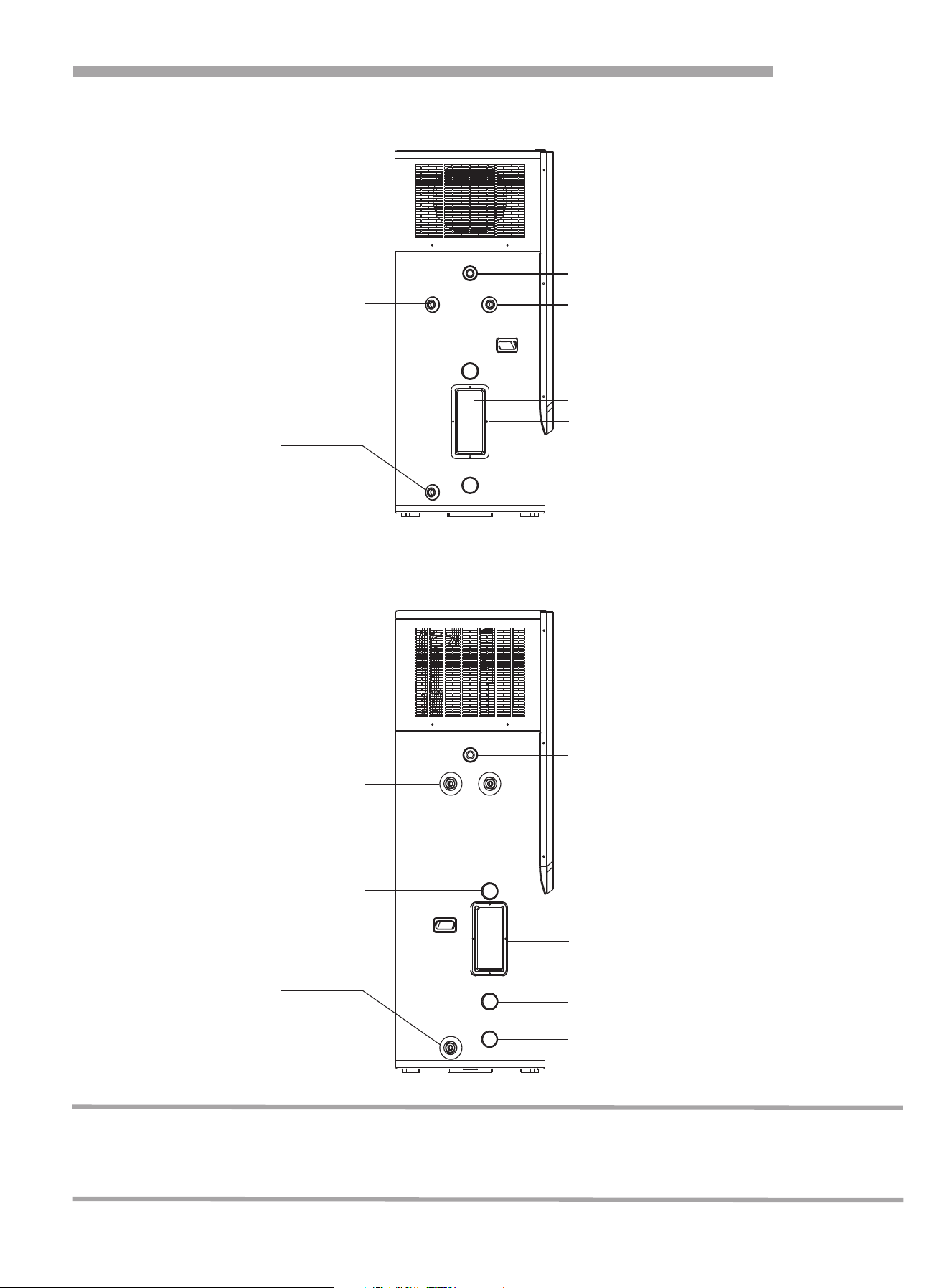
Part Names
8
NOTE:
All the pictures in this manual are for explanation purposes only. They may be slightly different from
the heat pump water heater you purchased (depending on the model). Please refer to the real sample
instead of the pictures of this manual.
Bottom temperature sensor
Bottom temperature sensor
Magnesium rod
Magnesium rod
Anode rod
Anode rod
Water inlet
Water inlet
Water outlet
Water outlet
Temperature sensor
Temperature sensor
Electric heater
Electric heater
1. AHS-210HF4GHB
2. AHS-270HF4GHB
PTR valve
PTR valve
Condensate water
Condensate water

Installation of Heat Pump
9
1. Choose a suitable location
1.1 Avoid installing this equipment indoors. If installed indoors, may cause overflow, noise or indoor temperature
changes which can influence comfort, please ensure preventive measures are taken in advance.
1.2 Ensure sufficient space for installation and maintenance.
1.3 Inlet or outlet air must have no obstacles and be sheltered from strong winds.
1.4 Dry and ventilated place is most suitable.
1.5 Support surface must be flat(horizontal angle must not be more than 2°), and able to bear heat pump’s
weight. The surface shall not increase any noise or shock.
1.6 Ensure position where noise and exhaust air aren’t immediately adjacent to neighbors’ property.
1.7 The place has no leaking combustible air.
1.8 Easy access to install connection pipe and electrical parts.
1.9 If heat pump installed in metal parts of a building, electrical insulation must comply with technical standard
on electrical equipment.
The location contains mineral oil such as cutting oil.
The location contains salt such as coastal areas.
The location has corrosive fumes such as spa's, or where there is sulfur gas.
The location has frequent changes to voltage and current.
The location has strong movement, such as a car or cabin.
Location with strong electromagnetic waves.
Location where there is oil, gas or oil spatter such as kitchen.
Location where the evaporation of acid or alkaline gas occurs.
Other location where there is special conditions.
NOTE:
In the region which the temperature is below 0 ºC, the heat pump must be installed indoor or other
positions where it will not be frozen for purposes of protecting connection pipe.
If used for those regions which the temperature is below 0 ºC, suitable measures must be taken to protect
pipes if the heat pump is installed outdoors.
Installation location that experiences high temperature or long-term exposure is prohibited, as it may
decrease lifetime of the product.
Notes: If installed in the following places, machine errors may occur. If unavoidable, please consult
your local authorized service point.
Installation of Heat Pump
10
3.1 Please leave enough space for installation and maintenance.
3.2 If heat pump is installed in the basement, indoors or other airtight space, please note exhaust and intake
circulation between surrounding air and outdoor air.
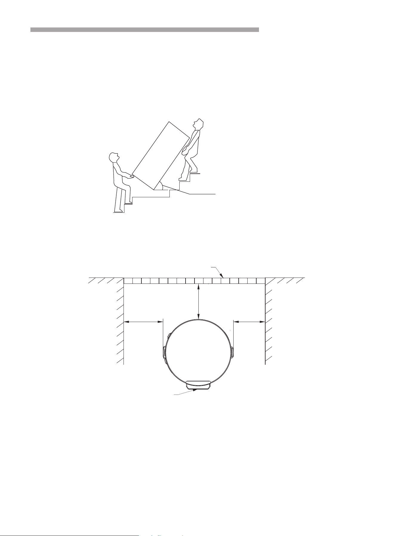
2. The Movement of Heat Pump
3. The Installation of Heat Pump
2.1 This heat pump is heavy requires at least two people to move and install it.
2.2 Please move the equipment according to the original factory packaging.
2.3 Please use protection during transit to avoid scratches and damage to the unit.
2.4 Do not touch fan with your hands or other objects.
2.5 Do not move the heat pump at an angle of <75°.
>85°
≥2 0 0 m m
≥20 0 m m
≥8 0 0 m m
Barrier
Control Panel
Installation of Heat Pump
11
3.3 If ducting is used, the air duct total length should be equal to or less than 6 meters, and the duct diameter
should be equal to or more than 150 mm.
≥200mm
≥200mm
≥500mm
1518
A
Model
Size(mm)
1010
B
1838
1330
AHS-210HF4GHB
AHS-270HF4GHB
4. Products External Dimension
B
A
Φ620mm
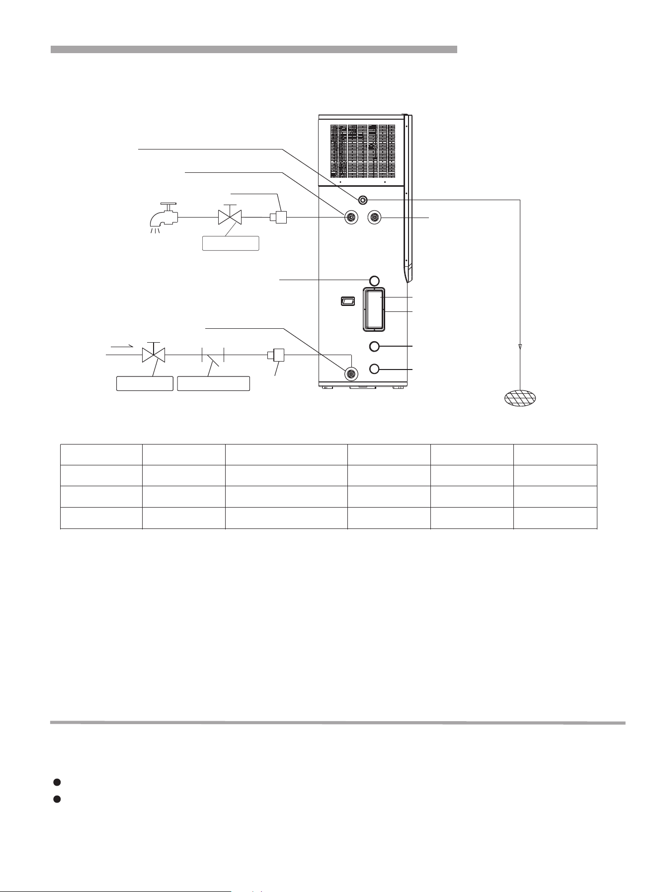
Bottom temperature
sensor
Magnesium rod
Anode rod
Electric heater
PTR Valve
Water For Domestic Use
Tap Water
Floor Drain
Condensed Water Outlet
Hot Water Outle
Cold Water Inlet
Temperature Sensor
Adapter
Ball Valve
Ball Valve
Y-Type Filter
Adapter
Pipe Line Connection
2. Water Quality Requirements
3. Water Pipe Installation Instructions
1. Pipe Connection Diagram
3.1 Please don’t use iron pipe for heat pump connections. CPVC pipe, PPR pipe or PB pipe or other pipe as per
local regulations is recommended.
3.2 Water pipes, connectors etc must be installed according to the drawing. If the ambient temperature is below
0 ℃, proper insulation must be installed for the water pipes.
3.3 Water inlet/outlet size is G3/4’’, external thread.
3.4 The water pipe’s working life must not be less than the heat pump’s working life.
3.5 Relief valve is G1/2’’, 0.8 MPa. After installation, ensure that the drainage pipe which connects to the relief
valve is not blocked.
PH value Total hardness Conductivity Sulphate ion Chlorine ion Ammonia ion
7 8.5~ < 50ppm <200μV/cm(25℃) None < 50ppm None
Sulfate ion Silicon Iron content Sodium Ca
< 50ppm < 50ppm < 0.3ppm No requirement < 50ppm
NOTE:
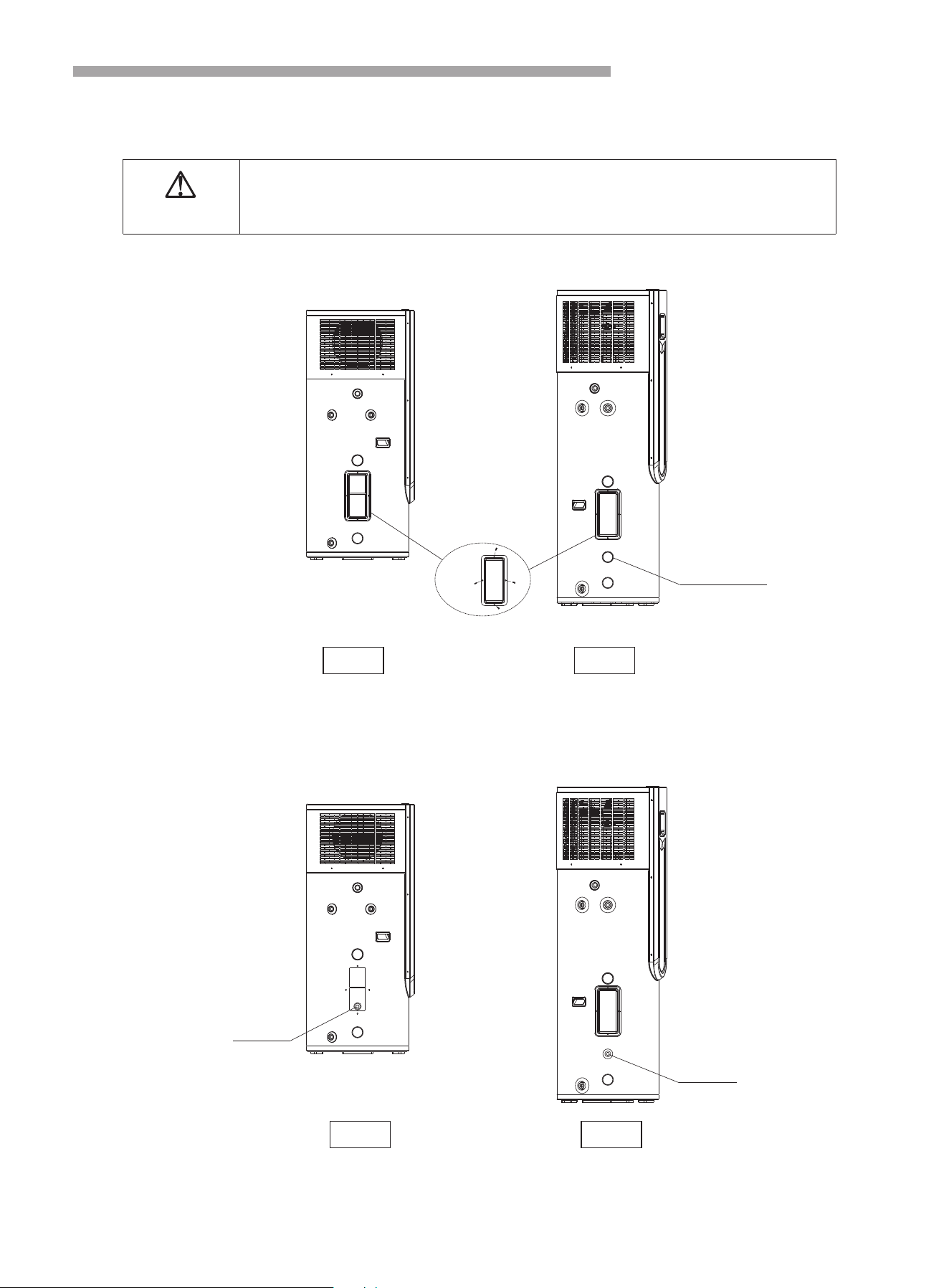
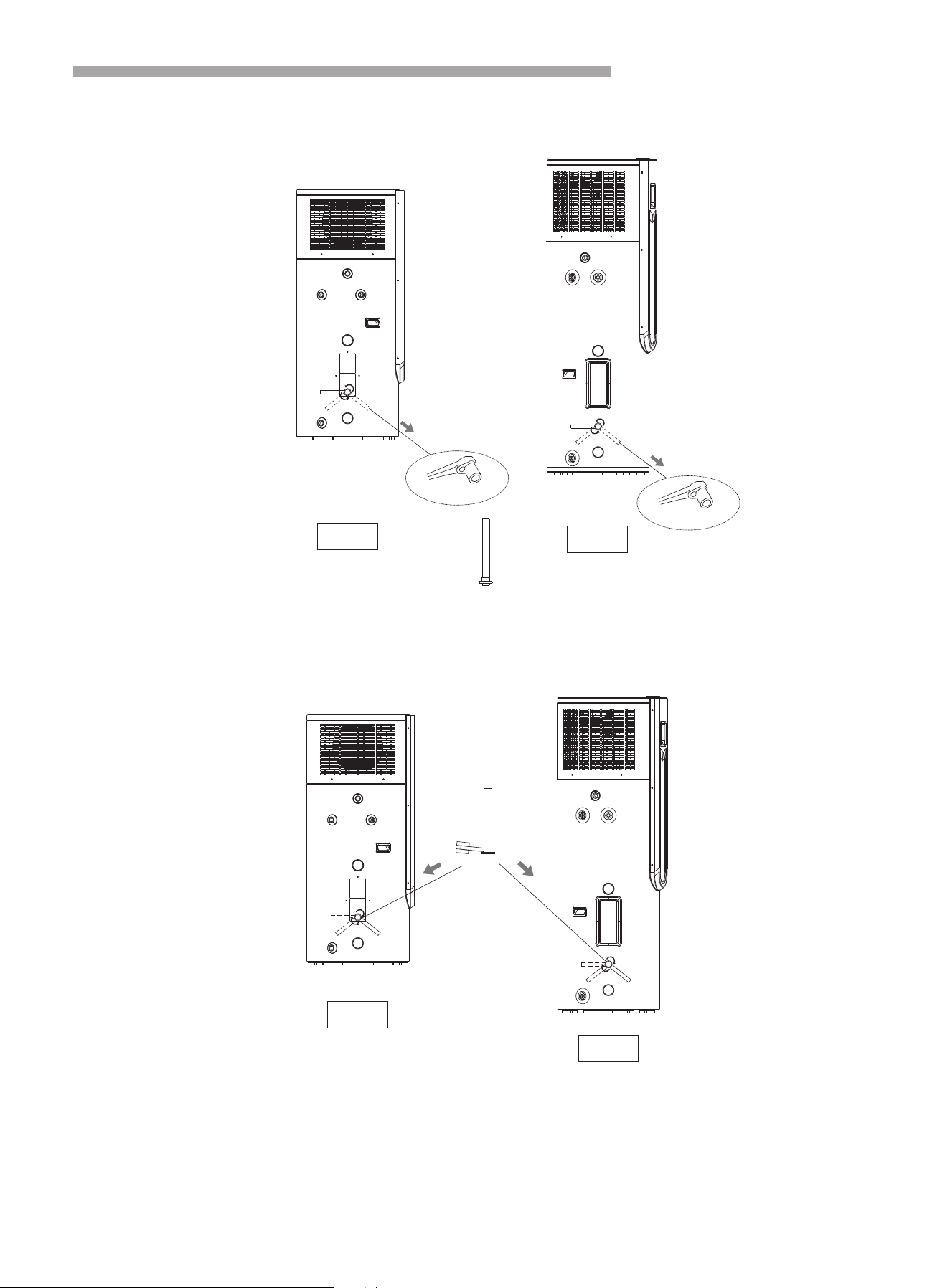
12
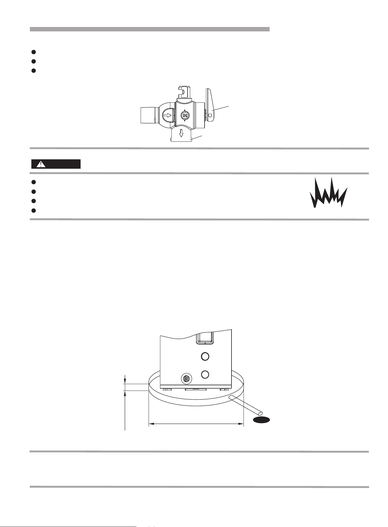
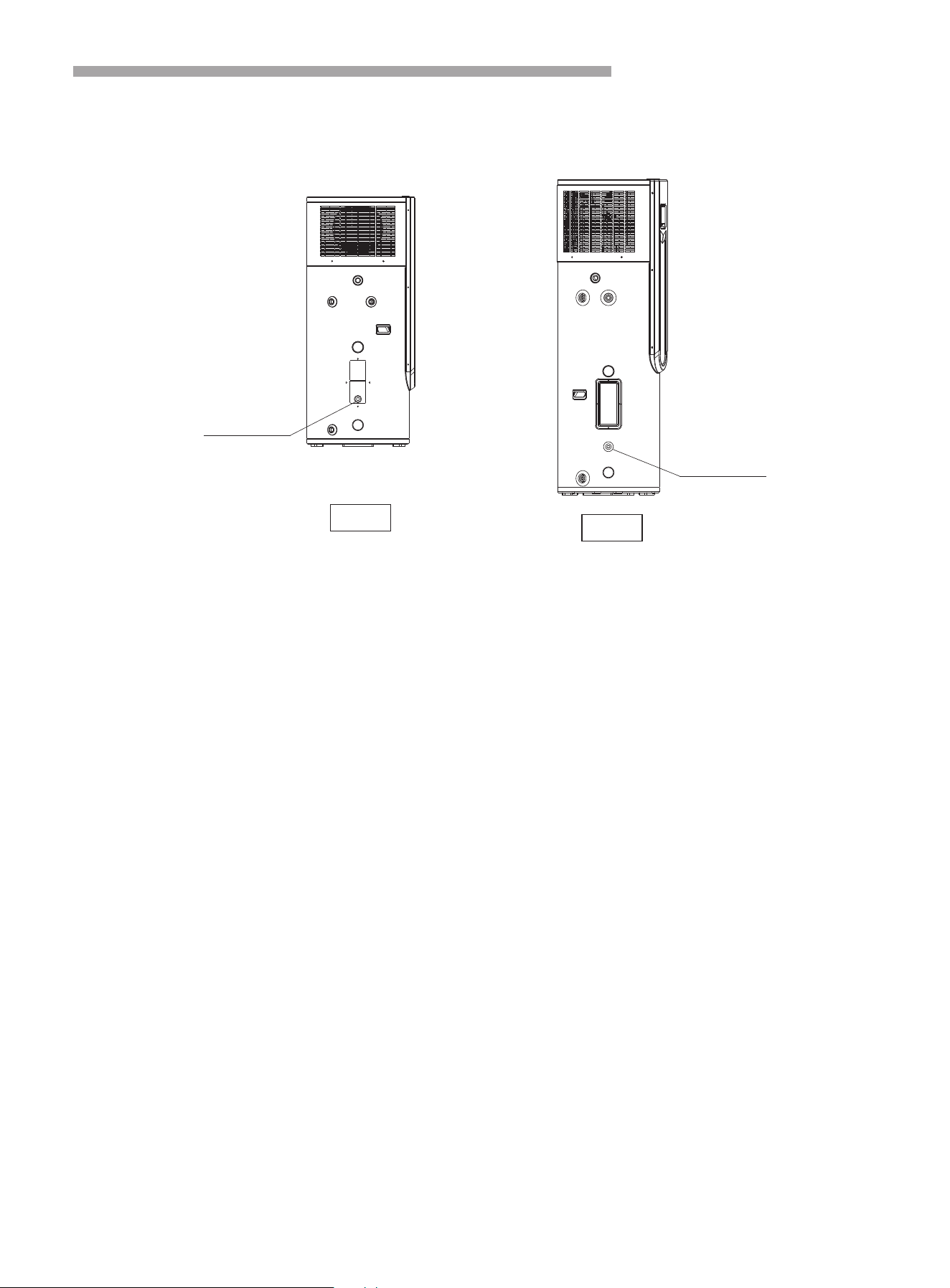
Checking the TPR valve (frequency: every half year - replace if required)
To ensure the TPR valve functions correctly, perform the following steps every six months, and replace it if
needed:
Locate the TPR valve on the left side of the unit.
Carefully use the lever to release the valve, allowing some water to drain from the tank. Note that the
expelled water may be very hot.
13
Pipe Line Connection
DANGER
3.6 After pipe installation is complete, open up the valve controlled cold water inlet and the valve controlled hot
water outlet to fill water into tank, you can stop when water overflows from water outlet, then inspect all piping
and ensure there is no water leakage. If leakage is found, it must be repaired and water tank filled again.
3.7 When intake pressure is below 0.15MPa, a booster pump needs to be installed to connect with inlet water
pipe for purpose of increasing water pressure. Water pressure must be greater than 0.15MPA after booster
installation. When intake pressure is greater than 0.65MPa, a relief valve needed to be installed to connect with
inlet water pipe for purpose of keeping your water tank in a long-term working state.
3.8 During heat pump operation, condensed water droplets may be formed. Drainage water port may be
unexpectedly blocked, which can make surface of equipment drip water. To ensure correct long-term operation,
we suggest a water tray. Please refer to the below chart.
Do not hold down the handle of safety valve.
Do not knock down safety valve.
Do not plug the drainage port.
Excretion pipe must be connected with a open drainage port.
Explosion Danger
Diameter is at least larger
50mm than heat pump
Max.22mm
When used in a location where the temperature is below 0℃, if the heat pump is installed outdoors, please take
measures to protect water pipe according to local minimum temperature to prevent frozen or damaged water
pipes.
NOTE:
If water flows freely during this process, it indicates that the TPR valve is still in good working condition.
If water does not flow freely, it suggests that the TPR valve needs replacement.
In the case of a required replacement, please contact your plumber or reach out to your service team for
assistance.
Handle
Drainage Pipe
Electrical Connections
14
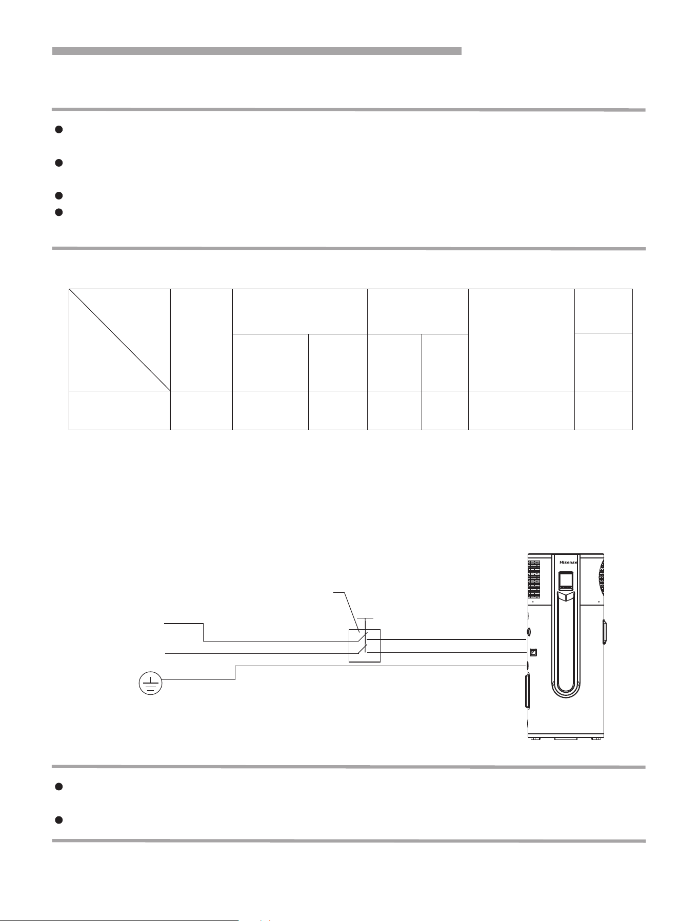
The equipment must be connected to the correct power supply, supply voltage must comply with rated
voltage.
Power supply circuit must be fitted with a grounding wire, and grounding wire of power supply must be
reliably connected with external grounding wire.
The installation must be undertaken by professional personnel based on provided circuit diagrams.
Leakage protection device must be installed correctly according to the National Technical Standard for
electrical equipment.
The power supply must have a leakage protection device installed according to the above diagram for your
safety.
The equipment cannot be used unless you have confirmed grounding wire is reliably connected.
Remark:
1 Please directly connect the plug to the socket on site if there is 15A socket there.
2 Make new power supply cable from circuit breaker and connect to the equipment by licensed
professional person if there is no 15A socket there.
NOTE:
WARNING
Item
Model
Circuit
breaker
Size
(continuous
length 30m)≤
Ground
wire(mm)
Capacity Fuse
Rated
current(A)
AHS-210HF4GHB
AHS-270HF4GHB
220V/50Hz ≥ 2.5 ≥ Φ1.0 ≥ 16 16 Below 30mA 0.1sec ≥ 16
Leakage protection
device
Minimum wire diameter
2
(mm )
Manual switch(A)
Power
supply
1. Power Specification
2. Leakage Protection
Manual switch
Power Supply
L
N
Ground wire
15
Electrical Connections
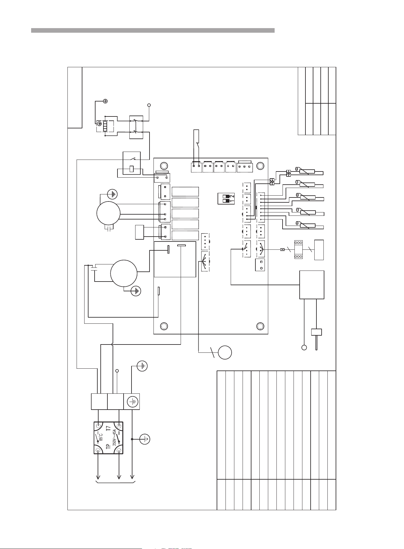
3. Internal Wiring Diagram
5
HPS
4WV
EEV
T4
T6
AC-N
DO3
T7
AI1
AI2
COM1
COM2
DO4/DO5 N
DI1 DI2
DI3
DI4
L H Com
COMP
N.O.
COM.
DO6
DO7
ON
EEV
COM3
Mainboard
COMP
Compressor
MF
Motor Fan
4WV
4 way valve
EEV
Electronic Expansion Valve
T1
T2
Coil temperature sensor
T3
Exhaust temperature sensor
HPS
High pressure switch
T5
Suction temperature sensor
Ambient temperature sensor
BU
BR
GN
BLUE
BROWN
GREEN
Y
YELLOW
WIRE COLOR CODE
WH
RD
BK
WHITE
RED
BLACK
OR
ORANGE
XT1
Terminal
RD
4WV
High speed
Low speed
Pump
E-heater
Wire
T4
Inlet temperature sensor
Y/GN
KA1
Relay
BK
MF
BU
BU
BU
RD
BU
WH
Power in
240V/~/50Hz
T4
T5
T3
T2
T1
A B
XT1
L
N
C2
Y
BU
BR
BU
RD
Y/GN
BK
COMP
S
R
C
C1
Capacitance
C1.C2
Electronic
anode
controller
Magnesium Rod
Water Tank
KA1
NO
COM
RD
BU
Temperature protector
HT1
WH
Controller
HT2
Y/GN
Y/GN
BRBR
BU
BU
BU
RD
32190001000793
BU
BU
BR
RD
E-heater
Y/GN
Y/GN
XT1.N
HT1
4
4
WIFI
HT2
Method of Application
16
When using the unit, please operate in the following order:
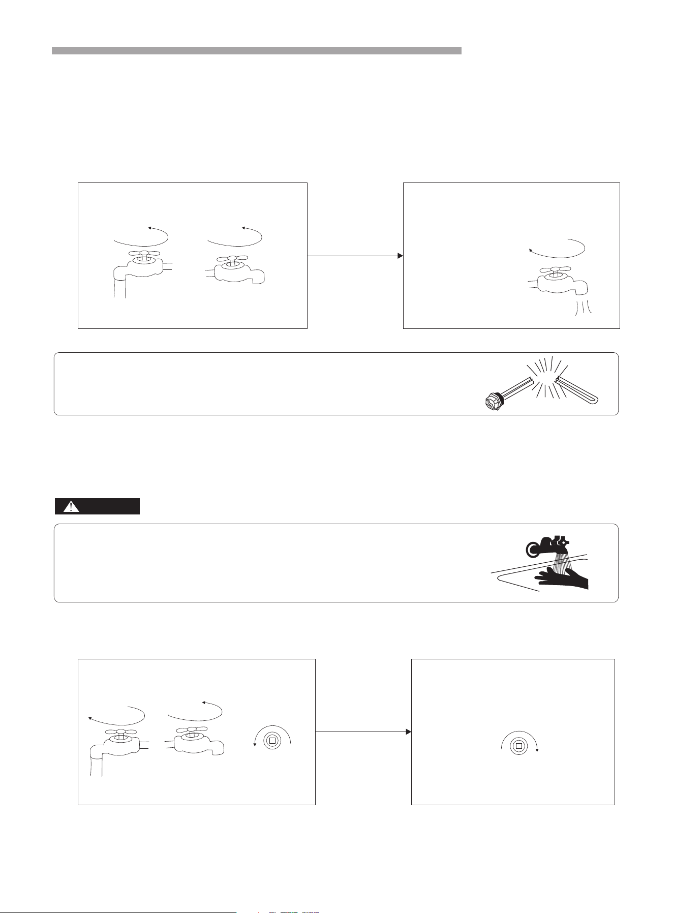
1. Feeding water: when using the unit for the first time (or reusing it after the tank is emptied), before
connecting the unit to power, please make sure the tank is full of water. Water feeding method is as per
below picture.
2. Connect the unit to power. Then the screen will turn on, which shows that the unit is connected to
power. The user can check different parameters by clicking the relative button on the screen (see next
page).
3. Water draining: before cleaning or moving the unit, please drain the water in the water heater. The
draining method is as per below picture:
Open the cold water inlet valve and hot
water outlet valve
When there is water flowing out from the
outlet, the tank is full with water. Close
the hot water outlet valve and the water
feeding is finished.
Cold water inlet
open
close
open
Hot water outlet
Feeding water
Hot water outlet
BURN
HOT
Operation without water in water tank may result in the damage of auxiliary
E-heater. Due to such damage, manufacturer will not be liable for any
damages caused by this issue.
Bang
Water temperature over 50℃ can cause severe burns instantly or death from
scalds. Children, disabled and elderly are at highest risk of being scalded.
Feel water before bathing or showering. Water temperature limiting valves
are recommended.
DANGER
Open the
outlet valve
Close the
inlet valve
Open the
draining valve
After the draining, please screw the
nut of the drainage outlet; the water
draining is finished.
Cold water
inlet
Drainage outlet
Drainage
outlet
screw tightenly
open
close
open
Hot water
outlet
Draining water

Instruction of operation
17
1. Control system specifications
1.1 Operating condition
Voltage:220V~±10%,50Hz±1Hz.
Ambient temperature: -7~+43℃.
Storage temperature: -20~+75℃.
Relative humidity: 0~95%RH.
Temperature accuracy: ±1℃.
1.2 Main function
Display the water temperature and setting temperature. Can also query the coil temperature, ambient
temperature, exhaust temperature etc.
Power cut memory function.
When power lost, clock will still work.
Timing on/off.
Automatic defrosting.
Forced defrost.
Large LCD display.
Protection functions.
The error code display and query.
Key-Lock Function.
Anti-freezing function.
When there is no wired controller or wired controller is broken, the system will recognize it, and control the
heat pump to run automatically.
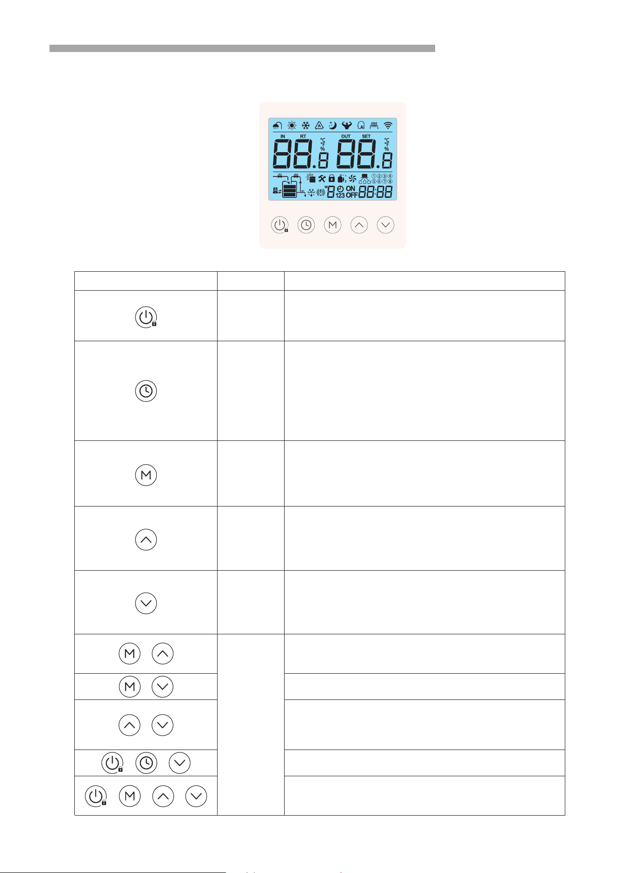
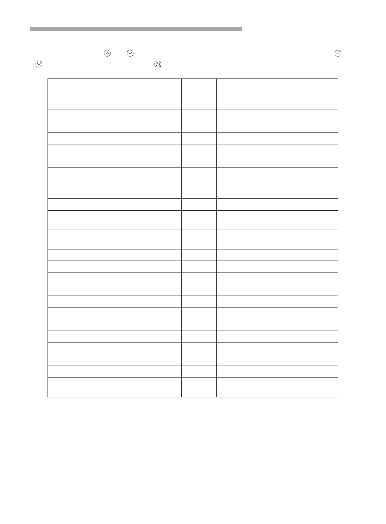
Instruction of operation
18
Symb Name Meaning
ON/OFF key
1. ON/OFF key (hold for 1 second).
2. Return key.
3. Escape key.
4. Unlock key (hold for 3 seconds).
1. Setting the clock, press the key will enter into clock
setting interface, and then press one time to switch the
hour and minute area.
2. Setting the timer (press the key and hold for 3s).
3. During timer setting, press the key and hold for 3s,
cancel the current timer setting.
4. During clock setting, press the key and fold for 3s,
enable or disable the week function.
1. Press the key and hold for 5s, enter into parameter
setting interface.
2. Press the key to change operation mode.
3. In parameter query interface, press the key enter into
value setting or save the setting.
1. Press the key to change temperature setting value or
parameter value or change hour and minute value.
2. Press the key and hold for 3s to query the system
status/parameter.
3. Page up.
1. Press the key to change temperature setting value or
parameter value or change hour and minute value.
2. Press the key and hold for 3s to query the system
status/parameter.
3. Page down.
When heat pump running in heating mode, press the two
keys and hold for 3s, turn ON/OFF Boost mode (turn
ON/OFF heating element).
When heat pump running, press the two keys and hold for
5s, start/exit defrosting mode.
When power on the heat pump, press the two keys and
hold for 5s, enter into Ventilation mode (running high
speed). Press the two keys for 3s, running low speed.
Press the two keys for 3s again, exit Ventilation mode.
Press the three keys and hold for 5s, turn ON/OFF
sterilization mode.
Power on within 5 minutes and don't turn on the heat
pump, press the four keys and hold for 5s,restore the
factory setting.
Clock key
Mode key
Up key
Down key
Combination
key
2.1 Controller Instruction
2. Wired controller and operation
+ + +
+
+
+
+ +
Instruction of operation
19
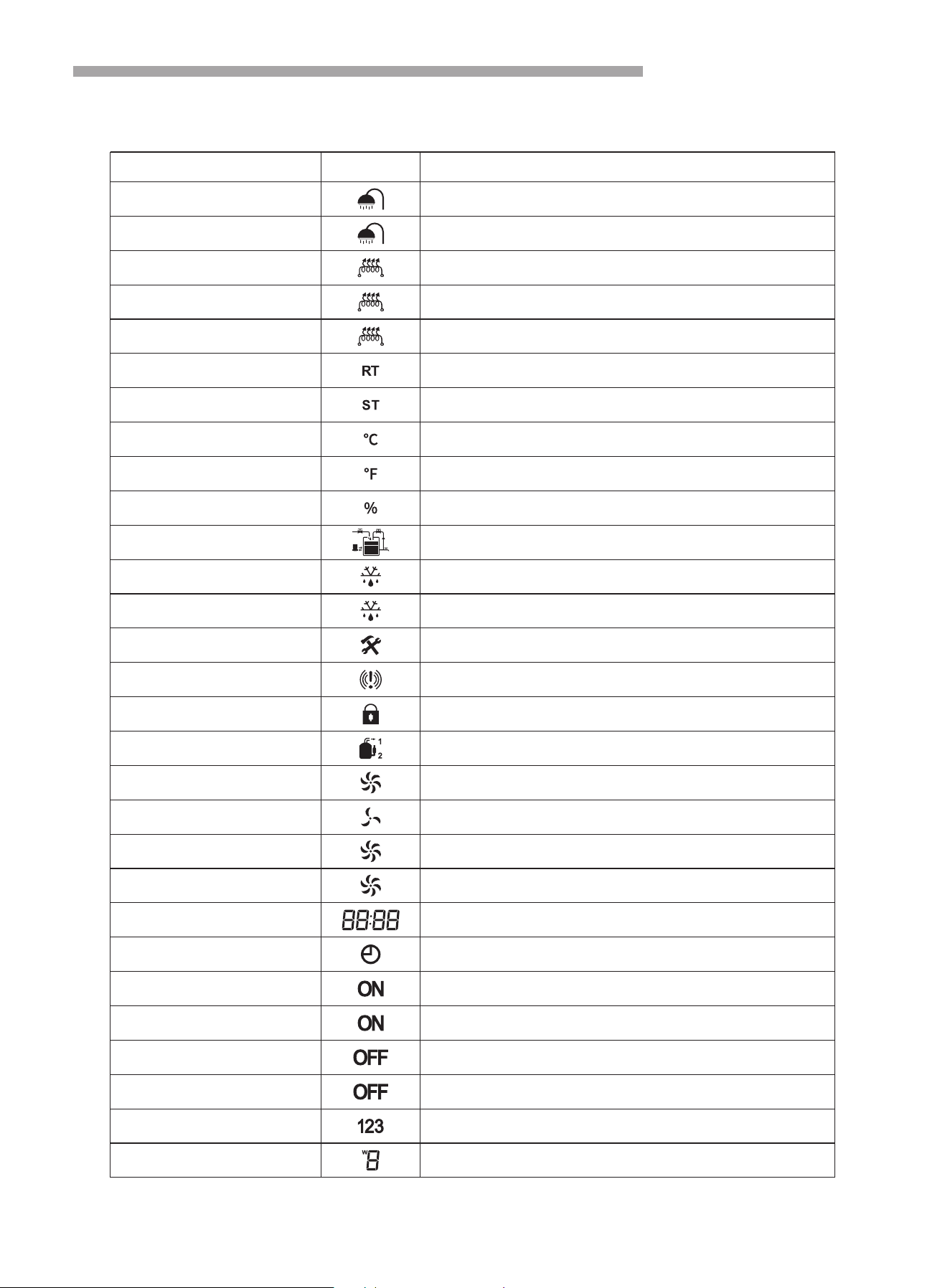
2.2 Instruction of the buttons
Status Symbol Meaning
Not bright
Light up
Light up
Flash for 1s
Flash for 2s
Light up
Light up
Light up
Light up
Light up
Light up
Flash
Light up
Light up
Light up
Light up
Light up
Light up
Light up
Flash for 1s
Flash for 2s
Display
Light up
Display
Flash
Display
Flash
Light up/Not bright
Display
Heat pump OFF or not in heating mode
In heating mode
Heating element ON
Run in Boost mode
Run in sterilization mode
Water temperature
Setting temperature
Degree centigrade
Degree Fahrenheit (reserved)
Percent(reserved)
Low/middle/high water level(reserved)
Heat pump OFF and refrigerant recovery mode
In defrosting mode
Maintenance mode
Error present
Lock screen
Compressor running
High fan speed
Low fan speed
Ventilation mode: high fan speed
Ventilation mode: low fan speed
Error code display
Timer ON
In timing ON period
Setting timing ON
In timing OFF period
Setting timing OFF
Timer number 1/2/3
Week
Operation Parameter Query
20
Name Code Remark
Fluorine cycle/water cycle heat pump 0 0 water cycle; 1 fluorine cycle= =
High pressure switch 1 0 disconnect 1 close= ; =
Low pressure switch 2 0=disconnect; 1=close
Water flow switch 3 0=disconnect; 1=close
EEV value 4 Measured value
Evaporator coil sensor 5 Measured value
Ambient temperature sensor 6 Measured value
Suction temp. 7 Measured value
Exhaust temperature sensor 8 Measured value
Water inlet temperature(Water tank) 9
Display value = measured value +
compensation value
Water outlet temperature 10
Display value = measured value +
compensation value
Compressor 11 0 stop= ; 1=running
4-way valve 12 0=stop; 1=running
High-speed fan 13 0=stop; 1=running
Low-speed fan 14 0=stop; 1=running
Circulation water pump 15 0=stop; 1=running
Heating element 16 0=stop; 1=running
Compressor working time before defrosting 17 Measured value
Link switch 18 0=Open; 1=Close
Program code 19 Show the code
Dial switch 20 0=Open; 1=Close
Dial switch 21 0=Open; 1=Close
Phase detecting value 22
0=OK; 3=Lack phase;
4=Phase fault; 5=No connection
When power on, press “ ” or “ ” button for 3 seconds, will enter into status query interface, press “ ” or
“ button to query each status; Press button will exit status query interface.
” “ ”
Operation Instruction
21
1. Lock and unlock
When the controller is in the normal display mode and there is no button operation for more than 60 seconds it
will get automatically locked. Press the key for 3 seconds to unlock, it will beep.
2. Turn ON/OFF the heat pump
When the controller is in the normal display mode, press button for more than 1 second to switch the
controller to the power ON or OFF mode.
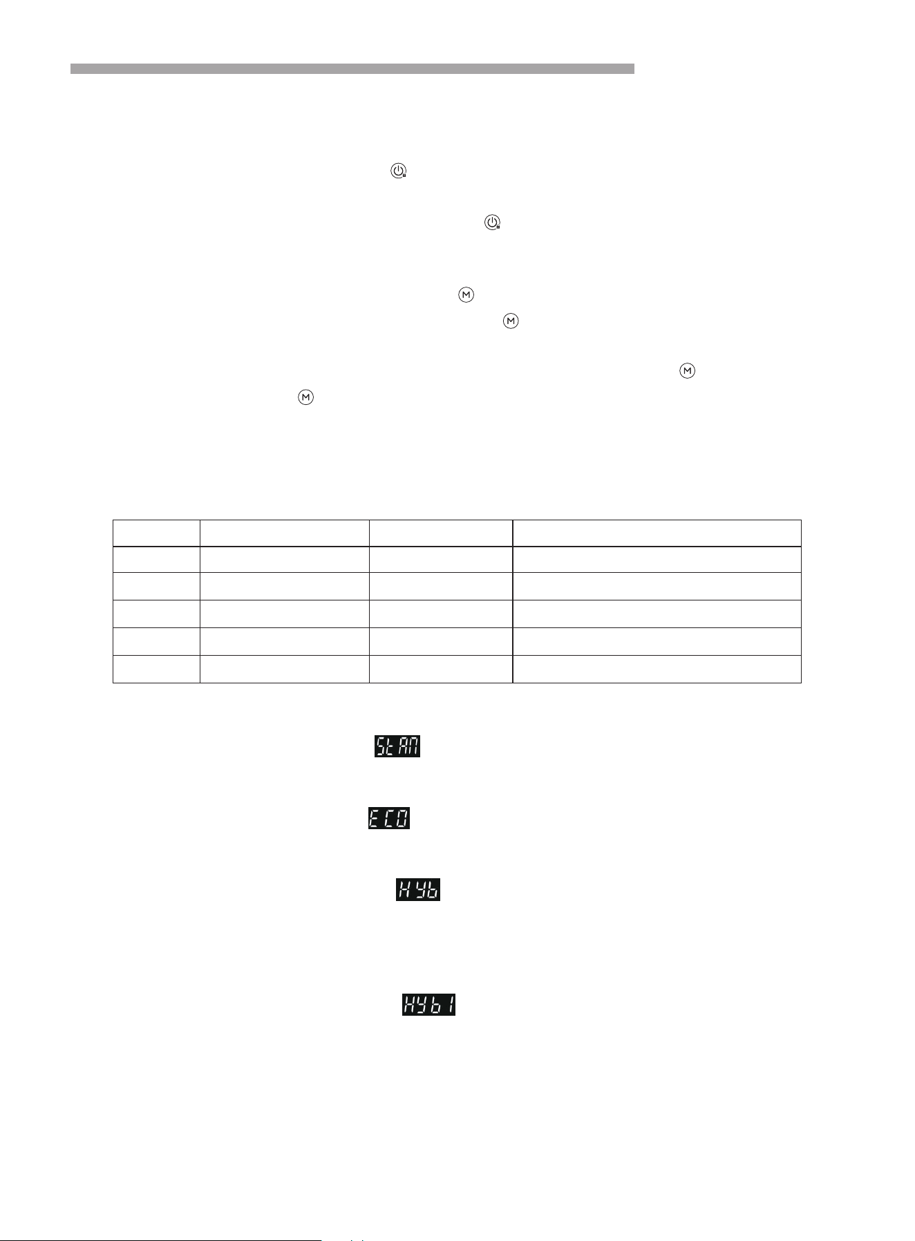
3. Operation mode selection
When the controller is in normal display mode, press key to show the existing operation mode, it will
display constantly for 8 seconds, before it disappear, press again to switch between different operating
modes;
The mode name will show at the clock area for 8 seconds each time when you touch key, when unlock, the
area will show clock, pressing key one time will query the existing operation mode.
The system default mode is STAN mode; When the unit is switched on for the first time, the system will operate
under STAN mode, later on the unit will always start as per previous setting mode. For changing the mode, refer
below instructions:
“ ”
“ ”
“ ”
“ ”
“ ”
“ ”
3.1 STAN mode (Standard mode)
In STAN mode, the controller will display , in this mode only heat pump operates and the default water
temperature setting is 55°C, setting range is 15°C~60°C, restart temperature difference is 5°C.
3.2 ECO mode (Economic mode)
In ECO mode, the controller will display , in this mode only heat pump operates and the default water
temperature setting is 55°C, setting range is 15°C~60°C, restart temperature difference is 12°C.
3.3 HYB mode (Hybrid mode)
Under HYB mode, the controller will display , in this mode, only heat pump run until the water
temperature reach at 60°C, when water temperature up to 60°C, heat pump will stop running, heating element
go on heating until the water temperature up to the setting temperature (if the set value more than 60°C). In this
mode, water temperature setting range is 15°C~65°C, restart temperature difference is 5°C.
3.4 HYB1 mode (Hybrid mode 1)
Under HYB1 mode, the controller will display , in this mode, only heat pump run until the water
temperature reach at 60°C, when water temperature up to 60°C, heat pump will stop running, heating element
go on heating until the water temperature up to the setting temperature (if the set value more than 60°C). In this
mode, water temperature setting range is 15°C~70°C, restart temperature difference is 5°C(default value).
“ ”
“ ”
“ ”
“ ”
S.No. Mode Symbol Setting Range
Standard Mode STAN
ECO
HYB
HYB1
ELE
15°C~60°C
Economic Mode
02
15°C~60°C
Hybrid Mode
03
15°C~65°C
Hybrid Mode 1
04
15°C~70°C
15°C~70°C
Electric Mode
05
01
Operation Modes Chart With Symbols

Operation Instruction
3.5 ELE mode (Heating element mode)
Under ELE mode, the controller will display , in this mode only the heating element will work to heat the
water. Water temperature setting range is 15°C~70°C, restart temperature difference is 10°C.
4. Water temperature set
Unlock the controller, in the main interface, press the or button to increase or decrease the water
temperature setting value.
5. Clock settings
In the main interface, click the button to enter the clock setting interface;
During clock setting, when hour part flash, press and hold the button for 3 seconds, enable / disable the
week function. If enable the week function, it will shows weekday (Monday: 1, Tuesday: 2...Sunday: 7).
If enabled the week function, then in the real-time clock setting interface, press the button, the weekday
part of the number flashes first, press or , you can set the weekday of the clock; if disabled the week
function, press the button, will set the hours first. the hour part of the number flashes, press or ,
you can set the hour of the clock;
when the hour part is set, press the button again, the number of minutes will flash, press or to set
the minutes of the clock;
After the minutes part is set, press the button again to confirm the real-time clock setting and return to the
main interface;
In the real-time clock setting interface, if there is no button operation for 60 seconds, the current clock setting
value will be confirmed and return to the main interface;
In the clock setting interface, press the button to confirm the clock setting value and return to the main
interface.
6. Work time settings
Press and hold the button for 3 seconds in the main interface to enable or disable the timer working mode.
Then press or to chose the timer No. 1 or No.2 or No.3 period.
When the timer No. 1 period is selected, the symbol flashes, press and release to switch the hour of the
start time(ON), the hour part of the number flashes, press or , you can set the hour. When the hour part
is set, press the button again, the number of minutes will flash, press or to set the minutes. After
the minutes part is set, press the button again set the hour of the end time(OFF), the hour part of the
number flashes, press or ,you can set the hour. When the hour part is set, press the button again,
the number of minutes will flash, press or to set the minutes.
After the minutes part is set, press the button again to confirm the setting and then switch to next period
(No. 2 or No. 3) timer working set, the setting method is the same as above.
If the start time of a certain working period is greater than the end time, the end time is considered to be of the
next day.
When all time periods are canceled, it is considered to be in working hours throughout the day.
When the start time and end time of a certain working period are the same, it discards the time period.
When enabled the week function, the timing work cycle time is week, if disabled the week function, the cycle
time is 24 hours.
“ ”
“ ” “ ”
“ ”
“ ”
“ ”
“ ” “ ”
“ ” “ ” “ ”
“ ” “ ” “ ”
“ ”
“ ”
“ ”
“ ” “ ”
“ ”
“ ” “ ”
“ ” “ ” “ ”
“ ”
“ ” “ ” “ ”
“ ” “ ”
“ ”
22

23
Operation Instruction
7. Forced defrosting
When the controller is in the normal display mode and the heat pump is ON. Press and buttons
together for more than 5 seconds to activate or deactivate the “Forced Defrost” function.
The symbol will light up when the “Forced Defrost” is ON.
8. Boost mode
When the controller is in the normal display and the heat pump in heating mode. Press and buttons
together for more than 3 seconds to enable or disable the boost mode, when enable the boost mode, heating
element ON, the symbol will flash for 1 second then light up, when Heat Pump Water Heater -34- / 44
the temperature reach at the set temperature, heating element off, the symbol will flash, means it is
operate in boost mode.
When turn off the heat pump, will exit boost mode.
9. Sterilization
Manual Sterilization Mode:
When the controller is in the normal display mode and the heat pump is ON. Press and and
buttons together for more than 5 seconds to sterilize the water tank, the symbol will flash for 2 seconds
then light up, and the heat pump will heate up the water to 60°C .
In automatic sterilization, the symbol will flash for 2 seconds then light up, and the heat pump will heate up
the water to 60°C. It will automatic sterilization every 7 days.
“ ” “ ”
“ ”
“ ” “ ”
“ ”
“ ”
“ ” “ ” “ ”
“ ”
“ ”

24
Trouble Shooting
Error code Error Description Possible Cause Solution
High pressure
protection
High pressure switch is
Connection is loose
broken/
Customer service to identify
the reasons
Communication
failure
Signal wire connection loose/There
is Strong magnetic field/PCB is
broken/Signal wire is broken
Replace the controller
communication line
(mainboard COM2 port)
Exhaust temp.
too high
Lack of refrigerant/Fluorine system
leak
Tank temp.
sensor failure
Coil temp.
sensor failure
Exhaust temp.
sensor failure
Ambient temp.
sensor failure
Suction temp.
sensor failure
Replace the T5temp. sensor
(Remark: refer to the diagram,
T1+T2+T3+T5 are in group parts)
E21
Sensor failure/Connection is loose
Replace the T2temp. sensor
E29
Sensor failure/Connection is loose
E16
Sensor failure/Connection is loose
Replace the T1temp. sensor
E18
Sensor failure/Connection is loose
Replace the T3temp. sensor
E05
E09
E12
Check then add refrigerant
E14
Sensor failure/Connection is loose
Replace the T4temp. sensor

25
Pilot run of Heat Pump
Please confirm the followings before pilot run of heat pump
The heat pump has been installed correctly.
Assembled pipe and wire are all correct.
Drain water line is not blocked.
Insulation materials are intact.
Ground wire is installed correctly.
Power voltage is equivalent to rated voltage of heat pump.
Inlet and outlet air port have no obstacle.
Air attached to water pipe is drained out, and all valves have been opened.
Leakage protection device works well.
Input water pressure is more than 0.15MPa.

26
Maintenance and Solution
1.1 Frequently check power plug and sockets and make sure both of them have been connected well and
reliably and have no over-heating effect.
1.2 When not used for a long time, especially where temperature is below 0 water filled in the water tank
must be drained out to prevent from damaging inner tank (operation shown in the above contents)
1.3 To make heat pump to keep a long-term and high efficiency working state, we suggest you should clean
inner tank up every half a year to remove accumulated sediment, please obey the following rules to clean inner
tank:
1.3.1 Turn off power supply of heat pump
1.3.2 Turn off cold water inlet valve, and open up hot water tap water
1.3.3 Connect drainage water with drain outlet through a soft pipe (temperature resistance of drainage pipe
must be more than 93 if drainage pipe is not suitable, please turn on cold water inlet valve, and turn on hot
water tap until water is not hot).
1.3.4 Turn on drainage water port of heat pump, clean water tank attached to inner tank up, if needed, you will
wash inner tank for many times to clear sediment
1.3.5 Turn off drainage water port, re-fill water into inner tank and recover power supply
1.4 Each device has been matched with one anode rod, and anode rod will be slowly consumed during the
process of protecting inner tank and extending use life. Under some water circumstance, anode rod and water
can rise reaction, hot water will be quickly corroded and rise leakage when anode rod has been used up. We
suggest check insulation materials every one year, if anode rod is used up, you can inquiry local service center
or technical department to acquire a new one
1.5 It is recommended that the temperature is not set higher than the temperature required, to reduce heat
losses and increase system efficiency
1.6 Filter should be cleaned up every one month to make sure heating effect
1.7 If used in regions where the temperature is below 0 you should take suitable measures to protect pipes in
case the heat pump is installed outdoors
,
,
,
,
°C
.
.
.
.
°C
.
.
.
.
.
°C
.
2.1 Checks to the area
Prior to beginning work on systems containing flammable refrigerants, safety checks are necessary to ensure
that the risk of ignition is minimised. For repair to the refrigerating system, 2 to 6 shall be completed prior to
conducting work on the system.
2.2 Work procedure
Work shall be undertaken under a controlled procedure so as to minimise the risk of a flammable gas or vapour
being present while the work is being performed.
2.3 General work area
All maintenance staff and others working in the local area shall be instructed on the nature of work being carried
out. Work in confined spaces shall be avoided.
2.4 Checking for presence of refrigerant
The area shall be checked with an appropriate refrigerant detector prior to and during work, to ensure the
technician is aware of potentially toxic or flammable atmospheres. Ensure that the leak detection equipment
being used is suitable for use with all applicable refrigerants, i.e.non-sparking, adequately sealed or intrinsically
safe.
2.5 Presence of fire extinguisher
If any hot work is to be conducted on the refrigerating equipment or any associated parts, appropriate fire
extinguishing equipment shall be available to hand. Have a dry powder or CO fire extinguisher adjacent to the
2
charging area.
1. Maintenance
2. Specific information for service personnel

27
Maintenance and Solution
2.6 No ignition sources
No person carrying out work in relation to a refrigerating system which involves exposing any pipe work shall
use any sources of ignition in such a manner that it may lead to the risk of fire or explosion. All possible ignition
sources, including cigarette smoking, should be kept sufficiently far away from the site of installation, repairing,
removing and disposal, during which refrigerant can possibly be released to the surrounding space. Prior to
work taking place, the area around the equipment is to be surveyed to make sure that there are no flammable
hazards or ignition risks. “No Smoking” signs shall be displayed.
2.7 Ventilated area
Ensure that the area is in the open or that it is adequately ventilated before breaking into the system or
conducting any hot work. A degree of ventilation shall continue during the period that the work is carried out. The
ventilation should safely disperse any released refrigerant and preferably expel it externally into the
atmosphere.
2.8 Checks to the refrigerating equipment
Where electrical components are being changed, they shall be fit for the purpose and to the correct
specification. At all times the manufacturer’s maintenance and service guidelines shall be followed. If in doubt,
consult the manufacturer’s technical department for assistance.
The following checks shall be applied to installations using flammable refrigerants:
– the actual refrigerant charge is in accordance with the room size within which the refrigerant containing parts
are installed
– the ventilation machinery and outlets are operating adequately and are not obstructed
– if an indirect refrigerating circuit is being used, the secondary circuit shall be checked for the presence of
refrigerant
– marking to the equipment continues to be visible and legible. Markings and signs that are illegible shall be
corrected
– refrigerating pipe or components are installed in a position where they are unlikely to be exposed to any
substance which may corrode refrigerant containing components, unless the components are constructed of
materials which are inherently resistant to being corroded or are suitably protected against being so corroded.
2.9 Checks to electrical devices
Repair and maintenance to electrical components shall include initial safety checks and component inspection
procedures. If a fault exists that could compromise safety, then no electrical supply shall be connected to the
circuit until it is satisfactorily dealt with. If the fault cannot be corrected immediately but it is necessary to
continue operation, an adequate temporary solution shall be used. This shall be reported to the owner of the
equipment so all parties are advised.
Initial safety checks shall include:
That capacitors are discharged: this shall be done in a safe manner to avoid possibility of sparking
That no live electrical components and wiring are exposed while charging, recovering or purging the system
That there is continuity of earth bonding.
.
.
.
.
.
.
3. Repairs to sealed components
3.1 During repairs to sealed components, all electrical supplies shall be disconnected from the equipment being
worked upon prior to any removal of sealed covers, etc. If it is absolutely necessary to have an electrical supply
to equipment during servicing, then a permanently operating form of leak detection shall be located at the most
critical point to warn of a potentially hazardous situation.
3.2 Particular attention shall be paid to the following to ensure that by working on electrical components, the
casing is not altered in such a way that the level of protection is affected. This shall include damage to cables,
excessive number of connections, terminals not made to original specification, damage to seals, incorrect fitting
of glands, etc.
Ensure that the apparatus is mounted securely.

28
Maintenance and Solution
Ensure that seals or sealing materials have not degraded to the point that they no longer serve the purpose of
preventing the ingress of flammable atmospheres. Replacement parts shall be in accordance with the
manufacturer’s specifications.
Do not apply any permanent inductive or capacitance loads to the circuit without ensuring that this will not
exceed the permissible voltage and current permitted for the equipment in use. The device must be operated in
safe conditions, and the device must be operated in rated conditions. Replace parts only with safety parts
specified by the manufacturer, otherwise other parts may cause the leaked refrigerant to catch fire.
Check that cabling will not be subject to wear, corrosion, excessive pressure, vibration, sharp edges or any
other adverse environmental effects. The check shall also take into account the effects of aging or continual
vibration from sources such as compressors or fans.
Under no circumstances shall potential sources of ignition be used in the searching for or detection of refrigerant
leaks. A halide torch (or any other detector using a naked flame) shall not be used.
The following leak detection methods are deemed acceptable for all refrigerant systems. Electronic leak
detectors may be used to detect refrigerant leaks but, in the case of flammable refrigerants, the sensitivity may
not be adequate, or may need re-calibration. (Detection equipment shall be calibrated in a refrigerant-free area.)
Ensure that the detector is not a potential source of ignition and is suitable for the refrigerant used. Leak
detection equipment shall be set at a percentage of the LFL of the refrigerant and shall be calibrated to the
refrigerant employed, and the appropriate percentage of gas (25 % maximum) is confirmed.
Leak detection fluids are also suitable for use with most refrigerants but the use of detergents containing
chlorine shall be avoided as the chlorine may react with the refrigerant and corrode the copper pipe-work.
NOTE Examples of leak detection fluids are
– bubble method,
– fluorescent method agents.
If a leak is suspected, all naked flames shall be removed/extinguished.
If a leakage of refrigerant is found which requires brazing, all of the refrigerant shall be recovered from the
system, or isolated (by means of shut off valves) in a part of the system remote from the leak.
When breaking into the refrigerant circuit to make repairs – or for any other purpose – conventional procedures
shall be used. However, for flammable refrigerants it is important that best practice is followed since
flammability is a consideration. The following procedure shall be adhered to:
Remove refrigerant
Purge the circuit with inert gas (optional for A2L)
Evacuate (optional for A2L)
Purge with inert gas (optional for A2L)
Open the circuit by cutting or brazing
The refrigerant charge shall be recovered into the correct recovery cylinders. For appliances containing
flammable refrigerants other than A2L refrigerants, the system shall be purged with oxygen-free nitrogen to
render the appliance safe for flammable refrigerants. This process may need to be repeated several times.
Compressed air or oxygen shall not be used for purging refrigerant systems.
.
.
.
.
.
5. Cabling
6. Detection of flammable refrigerants
7. Removal and evacuation
4. Repair to intrinsically safe components

29
Maintenance and Solution
For appliances containing flammable refrigerants, other than A2L refrigerants, refrigerants purging shall be
achieved by breaking the vacuum in the system with oxygen-free nitrogen and continuing to fill until the working
pressure is achieved, then venting to atmosphere, and finally pulling down to a vacuum. This process shall be
repeated until no refrigerant is within the system. When the final oxygen-free nitrogen charge is used, the
system shall be vented down to atmospheric pressure to enable work to take place. This operation is absolutely
vital if brazing operations on the pipe-work are to take place.
Ensure that the outlet for the vacuum pump is not close to any potential ignition sources and that ventilation is
available.
In addition to conventional charging procedures, the following requirements shall be followed.
Ensure that contamination of different refrigerants does not occur when using charging equipment. Hoses or
lines shall be as short as possible to minimise the amount of refrigerant contained in them.
Cylinders shall be kept in an appropriate position according to the instructions.
Ensure that the refrigerating system is earthed prior to charging the system with refrigerant.
Label the system when charging is complete (if not already).
Extreme care shall be taken not to overfill the refrigerating system.
Prior to recharging the system, it shall be pressure-tested with the appropriate purging gas. The system shall be
leak-tested on completion of charging but prior to commissioning. A follow up leak test shall be carried out prior
to leaving the site.
Before carrying out this procedure, it is essential that the technician is completely familiar with the equipment
and all its detail. It is recommended good practice that all refrigerants are recovered safely. Prior to the task
being carried out, an oil and refrigerant sample shall be taken in case analysis is required prior to re-use of
recovered refrigerant. It is essential that electrical power is available before the task is commenced.
9.1 Become familiar with the equipment and its operation.
9.2 Isolate system electrically.
9.3 Before attempting the procedure, ensure that:
Mechanical handling equipment is available, if required, for handling refrigerant cylinders
All personal protective equipment is available and being used correctly
The recovery process is supervised at all times by a competent person
Recovery equipment and cylinders conform to the appropriate standards.
9.4 Pump down refrigerant system, if possible.
9.5 If a vacuum is not possible, make a manifold so that refrigerant can be removed from various parts of the
system.
9.6 Make sure that cylinder is situated on the scales before recovery takes place.
9.7 Start the recovery machine and operate in accordance with instructions.
9.8 Do not overfill cylinders (no more than 80 % volume liquid charge).
9.9 Do not exceed the maximum working pressure of the cylinder, even temporarily.
9.10 When the cylinders have been filled correctly and the process completed, make sure that the cylinders and
the equipment are removed from site promptly and all isolation valves on the equipment are closed off.
9.11 Recovered refrigerant shall not be charged into another refrigerating system unless it has been cleaned
and checked
.
.
.
.
8. Charging procedures
9. Decommissioning

30
Maintenance and Solution
Equipment shall be labelled stating that it has been de-commissioned and emptied of refrigerant. The label shall
be dated and signed. For appliances containing flammable refrigerants, ensure that there are labels on the
equipment stating the equipment contains flammable refrigerant.
When removing refrigerant from a system, either for servicing or decommissioning, it is recommended good
practice that all refrigerants are removed safely.
When transferring refrigerant into cylinders, ensure that only appropriate refrigerant recovery cylinders are
employed. Ensure that the correct number of cylinders for holding the total system charge is available. All
cylinders to be used are designated for the recovered refrigerant and labelled for that refrigerant (i.e. special
cylinders for the recovery of refrigerant). Cylinders shall be complete with pressure-relief valve and associated
shut-off valves in good working order. Empty recovery cylinders are evacuated and, if possible, cooled before
recovery occurs.
The recovery equipment shall be in good working order with a set of instructions concerning the equipment that
is at hand and shall be suitable for the recovery of all appropriate refrigerants including, when applicable,
flammable refrigerants. In addition, a set of calibrated weighing scales shall be available and in good working
order. Hoses shall be complete with leak-free disconnect couplings and in good condition. Before using the
recovery machine, check that it is in satisfactory working order, has been properly maintained and that any
associated electrical components are sealed to prevent ignition in the event of a refrigerant release. Consult
manufacturer if in doubt.
The recovered refrigerant shall be returned to the refrigerant supplier in the correct recovery cylinder, and the
relevant waste transfer note arranged. Do not mix refrigerants in recovery units and especially not in cylinders.
If compressors or compressor oils are to be removed, ensure that they have been evacuated to an acceptable
level to make certain that flammable refrigerant does not remain within the lubricant. The evacuation process
shall be carried out prior to returning the compressor to the suppliers. Only electric heating to the compressor
body shall be employed to accelerate this process. When oil is drained from a system, it shall be carried out
safely.
10. Labelling
12. Error & Approaches
11. Recovery
Error Reason Approach
The outlet water is cold.
The screen is dark.
No water out from the
hot water outlet
Water leakage
1. The plug is not plugged properly.
2. The temperature controller is on
the lowest temperature control
state.
3. The temperature controller is
damaged.
4. The circuit board of the indicator
lamp is damaged.
1. The tap water is cut off.
2. The water pressure is too low.
3. The tap water inlet valve is
closed.
Bad tightness in the connecting
points between pipes.
1. Plug in properly.
2. Set the temperature of the
controller in higher state.
3.Inform the service
department.
1. Waiting for the restore of the
tap water.
2. Wait and use when the water
pressure is raised.
3. Open the tap water inlet
valve.
Improve the tightness of the
connecting points.
Check it once a year, generally replace once every two years.
13.1 Check the decorative cover of anode rod from the front of water tank.
13.2 Remove the decorative cover and we can see the anode rod.
31
Maintenance and Solution
13.Anode rod replacement
Caution
Anode rod
Anode rod
210L 270L
Screw
210L 270L
Decorative cover
32
Maintenance and Solution
13.3 Use the socket wrench(Φ21) to screw tease out the anode rod.
270L
210L
Socket wrench
Socket wrench
13.4 Wrap the raw material belt on the screw thread of a new piece of anode rod, and install it.
270L
210L
33
Maintenance and Solution
13.5 Make sure the anode rod is tightened enough and put the cover back.
210L
270L
Recovery Cover
Recovery Cover

34
After-sale Service
If your hot water heater can not operate normally, please turn off the unit and cut off the power supply at
once, then contact our service center or technical department.


Version No.14400003001340-A
Correct Disposal of this product
This marking indicates that this product should not be disposed with other household wastes throughout the EU.To prevent
possible harm to the environment or human health from uncontrolled waste disposal, recycle it responsibly to promote the
sustainable reuse of material resources.To return you used device,please use the return and collection systems or contact
the retailer where the product was purchased.They can take this product for environmental safe recycling.