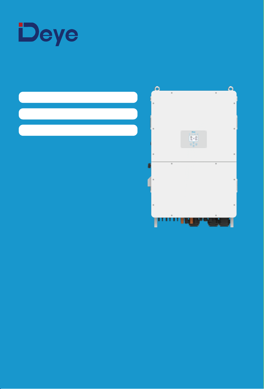
Hybrid Inverter
User Manual
SUN-100K-SG02HP3-EU-GM10
SUN-100K-SG02HP3-EU-GM8
SUN-125K-SG02HP3-EU-GM10

�������������������
�������������������
01-02
02-06
Contents
06-30
��������������������������
52-53
�����������������������
��������������������
4.
OPERATION
4.1 Power ON/OFF
4.2 Operation and Display Panel
31
32-52
������������������
������������������������
5. LCD Display Icons
5.1 Main Screen
5.2 Detail page
5.3 Curve Page-Solar & Load & Grid
5.4 Setting Menu
5.5 Basic setup Menu
5.6 Grid Setup Menu
5.7 Battery Setup Menu
5.8 Quick Control Menu
5.9 Info and Fault Code Menu
5.10 Gen and Aux Load Menu
5.11 System Mode Menu
5.12 Network Menu
5.13 Advanced Menu
6. Mode
7. Warranty
53-54
60-61
�����������������������
61-63
�����������������������
65
�����������������������
64
���������������
9. Datasheet
10.Appendix I
11.Appendix II
12.Appendix III
13.EU Declaration of Conformity
65-67
8. Troubleshooting
������������������������
54-59
�����������������������
1. Safety Introductions
2. Product instructions
2.1 Product Overview
2.2 Product Size
2.3 Product Features
2.4 Basic System Architecture
2.5 Product handling requirements
3. Installation
3.1Parts list
3.2 Mounting instructions
3.3 Function port definition
3.4 Battery connection
3.5Grid connection and backup load connection
3.6 PV Connection
3.7 Meter or CT installation
3.8 Earth Connection(mandatory)
3.9 Data logger connection
3.10 Wiring diagram with neutral line grounded
3.11 Wiring diagram with neutral line ungrounded
3.12 Typical application diagram of on-grid system
3.13 Typical application diagram of diesel generator
3.14 Three phase parallel connection diagram
- 01 -
About This Manual
This manual provides information and guidelines for the installation, operation, and
maintenance of the SUN-100K-SG02HP3-EU-GM8/SUN-(100-125)K-SG02HP3-EU-GM10
inverter. Please note that it does not contain comprehensive information about the
photovoltaic (PV) system.
How to Use This Manual
Before undertaking any operation involving the inverter, it is crucial to thoroughly read this manual
and any associated documents. Ensure that these documents are stored safely and are readily
accessible at all times.
Please be aware that the contents of this manual may undergo periodic updates or revisions as a
result of ongoing product development. Consequently, the information contained herein is subject
to change without prior notice. The latest manual can be acquired via [email protected]
1. Safety Introductions
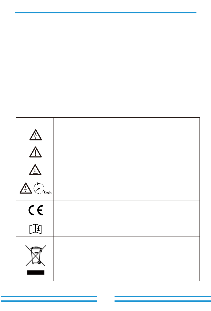
Labels description
Label
Description
Please read the instructions carefully before use.
CE mark of conformity
Symbol for the marking of electrical and electronics devices according to
Directive ����/��/EC. Indicates that the device, accessories and the
packaging must not be disposed as unsorted municipal waste and must be
collected separately at the end of the usage. Please follow Local Ordinances
or Regulations for disposal or contact an authorized representative of the
manufacturer for information concerning the decommissioning of
equipment.
Caution, risk of electric shock symbol indicates important safety
instructions, which if not correctly followed, could result in electric shock.
The DC input terminals of the inverter must not be grounded.
Surface high temperature, Please do not touch the inverter case.
The AC and DC circuits must be disconnected separately, and the
maintenance personnel must wait for � minutes before they are
completely powered off before they can start working.
2. Product Introductions
This is a multifunctional inverter, combining functions of inverter, solar charger and battery
charger to offer uninterruptible power support with portable size. Its comprehensive LCD display
offers user configurable and easy accessible button operation such as battery charging, AC/solar
charging, and acceptable input voltage based on different applications.
· This chapter contains important safety and operating instructions. Read and keep this manual
for future reference.
· Before using the inverter, please read the instructions and warning signs of the battery and
corresponding sections in the instruction manual.
· Do not disassemble the inverter. If you need maintenance or repair, take it to a professional
service center.
· Improper reassembly may result in electric shock or fire.
· To reduce risk of electric shock, disconnect all wires before attempting any maintenance or
cleaning. Turning off the unit will not reduce this risk.
· Caution: Only qualified personnel can install this device with battery.
· Never charge a frozen battery.
· For optimum operation of this inverter, please follow required specification to select appropriate
cable size. It is very important to correctly operate this inverter.
· Be very cautious when working with metal tools on or around batteries. Dropping a tool may
cause a spark or short circuit in batteries or other electrical parts, even cause an explosion.
· Please strictly follow installation procedure when you want to disconnect AC or DC terminals.
Please refer to "Installation" section of this manual for the details.
· Grounding instructions - this inverter should be connected to a permanent grounded wiring
system. Be sure to comply with local requirements and regulation to install this inverter.
· Never cause AC output and DC input short circuited. Do not connect to the mains when DC
input short circuits.
- 02 -
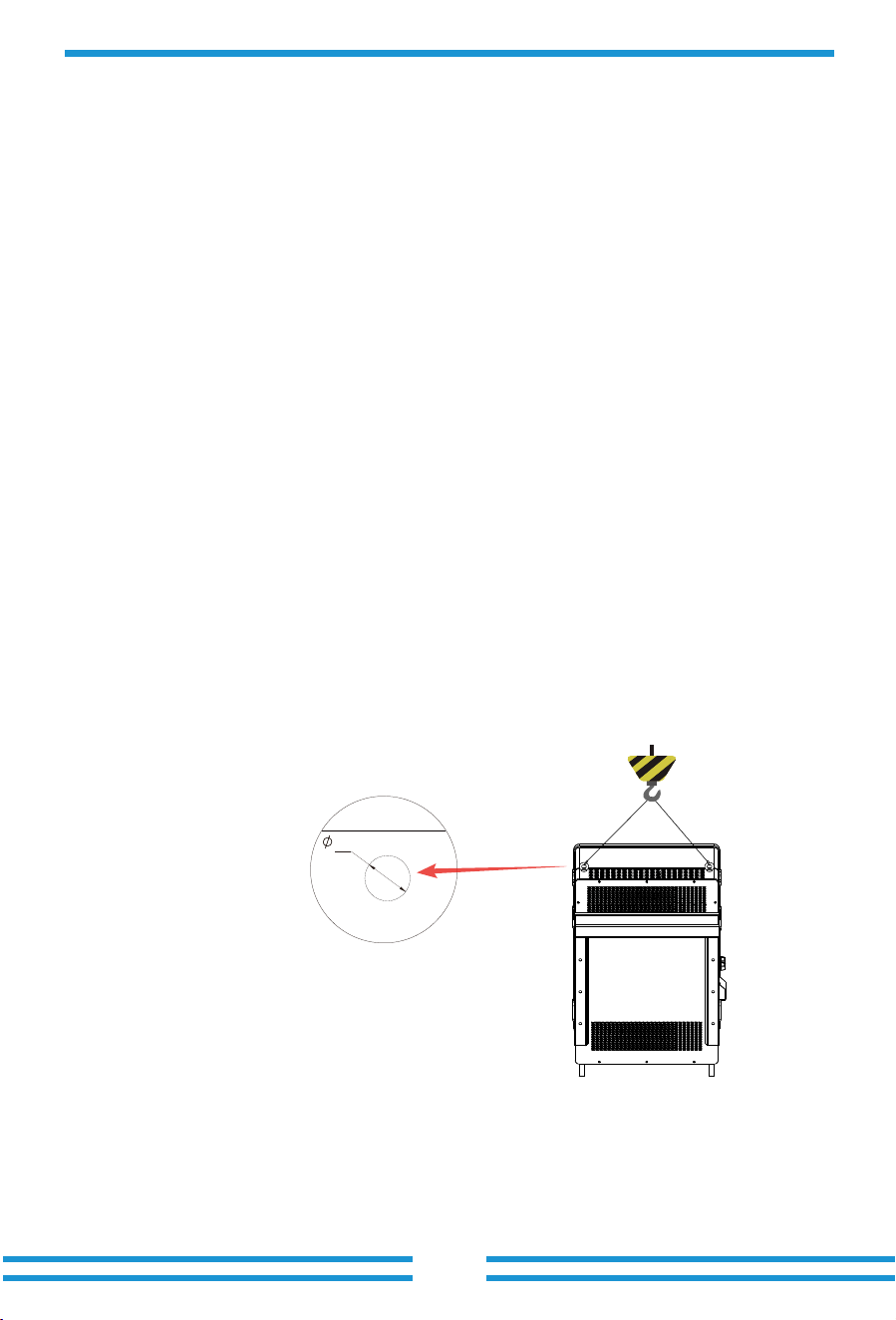
Hoisting Notes
If the inverter is installed in a high position, you can hung it up.
• Only trained and approved personnel are allowed to perform hoisting operations.
• Install temporary warning signs or fences to far away the hoisting area.
• Make sure that the foundation where hoisting is performed on meets the load bearing
requirements.
• Before hoisting objects, make sure that hoisting tools are firmly secured onto a fixed object or
wall that meets the load-bearing requirements.
• When hoisting, do not stay under the crane or the hoisted objects.
• Do not drag steel ropes and hoisting tools or bump the hoisted things
against hard things when hoisting.
12.5
BAT1+ BAT1- BAT2+ BAT2-
COM 1 COM 2 COM3
LOAD GRID
GEN
+
-
+
-
+
-
+
-
+
-
+
-
+
-
+
-
+
-
+
-
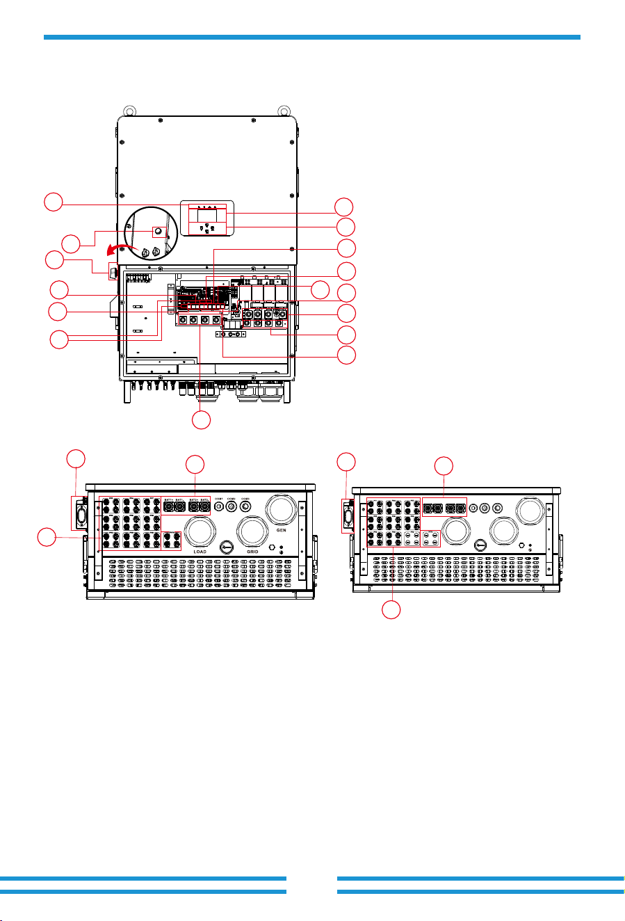
2.1 Product Overview
- 03 -
1
2
3
4
6
5
7
8
10
11
9
12
13
19
15
14
16
17
18
1: Inverter indicators
SUN-100/125K-SG02HP3-EU-GM10 SUN-100K-SG02HP3-EU-GM8
2: LCD display
3: Function buttons
5: DC switch
4: Power on/off button
6: Meter port
7: Parallel port
8: CAN port
9: DRM port
10: BMS port
11: RS485 port
12: Generator input 18: Logger interface
19: LAN port
17: Battery input
13: Grid
15: Load
14: Function port
16: PV input
16
17
18
BAT1+ BAT1- BAT2+ BAT2-
COM1 CO M2 COM3
LOA D GRI D
GEN
+
-
+
-
+
-
+
-
+
-
+
-
+
-
+
-
+
-
+
-
- 04 -
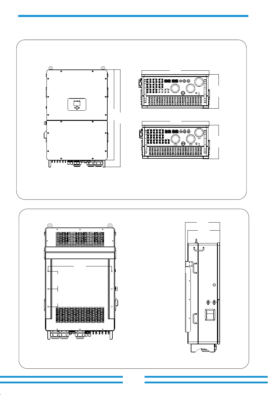
2.2 Product Size
Inverter Size
734. 00 mm
369. 00 mm
1091 .0 0 mm
1174 .00 mm
344.00 mm
369.00 mm
668.00 mm
185. 00 mm
185. 00 mm
SUN-100K-SG02HP3-EU-GM8
SUN-100/125K-SG02HP3-EU-GM10
73 4.00 mm
36 9. 00 mm
PV SWIT CH1 PV SW ITCH2
ON/O FF
WIFI
- 05 -
2.3 Product Features
- 230V/400V Three phase Pure sine wave inverter.
- Self-consumption and feed-in to the grid.
- Auto restart while AC is recovering.
- Programmable supply priority for battery or grid.
- Programmable multiple operation modes: On grid, off grid and UPS.
- Configurable battery charging current/voltage based on applications by LCD setting.
- Configurable AC/Solar/Generator Charger priority by LCD setting.
- Compatible with mains voltage or generator power.
- Overload/over temperature/short circuit protection.
- Smart battery charger design for optimized battery performance
- With limit function, prevent excess power overflow to the grid.
- Supporting WIFI monitoring and have 3 or 4 built-in MPP Trackers, 1 MPP Tracker can
connect 2 PV strings.
- Smart three-stage charging strategy with customizable settings can optimize battery performance.
- Time of use function.
- Smart Load Function.
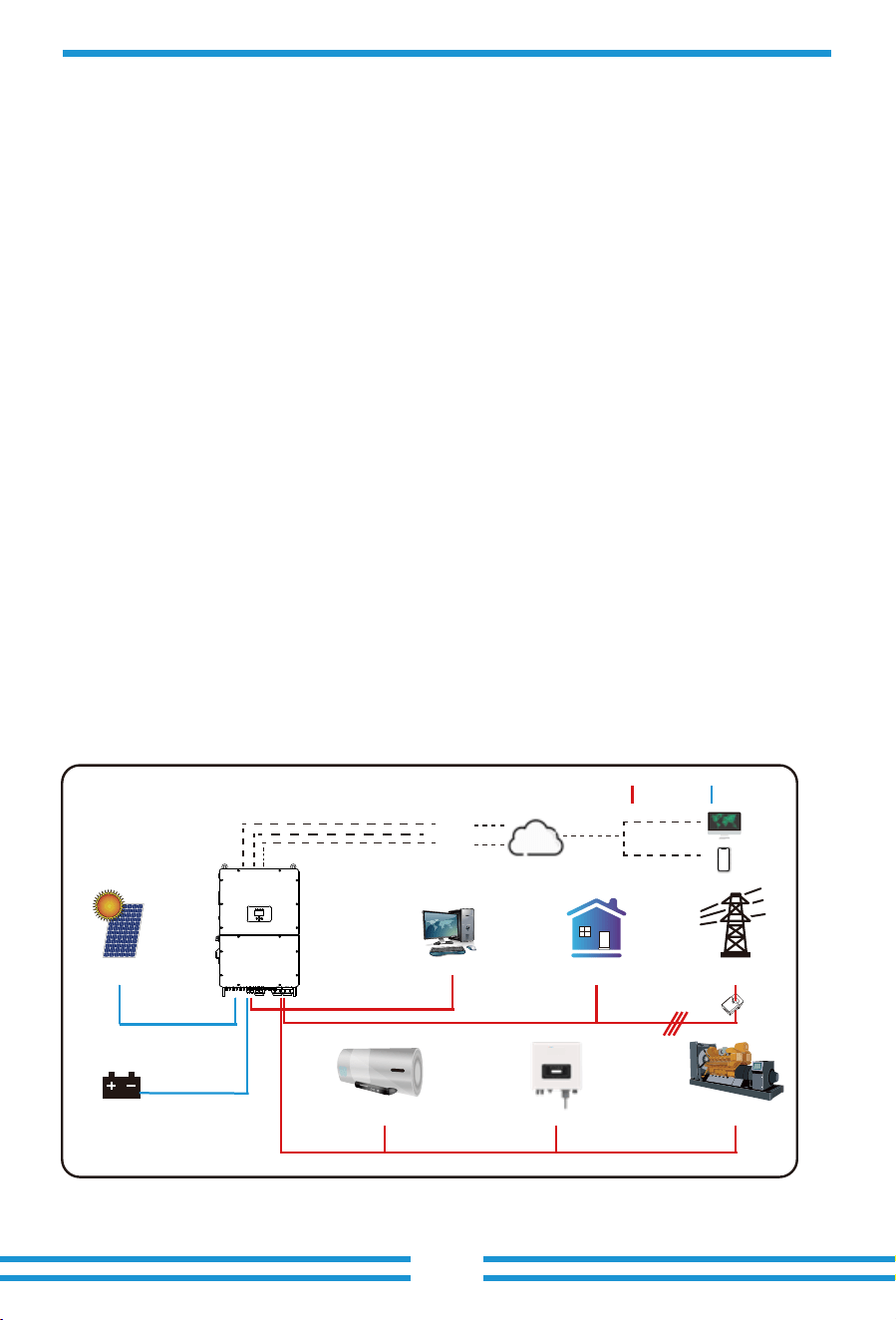
2.4 Basic System Architecture
The following illustration shows basic application of this inverter.
It also includes following devices to have a complete running system.
- Generator(Fro off-grid mode)or Utility Grid
- PV modules
Consult with your system integrator for other possible system architectures depending on your
requirements.
This inverter is designed to power a range of appliances commonly found in homes and offices,
including motor type appliances like refrigerators and air conditioning units. Before use, it's
advisable to verify appliance compatibility with this inverter.
The generator interface should not be connected to both the generator and the smart load
simultaneously. The generator only can be connected in stand-alone scenario. When the grid be
connected, the generator should not be connected simultaneously.
GridBackup Load*
Cloud services
On-Grid Home Load
GeneratorGrid-connected InverterSmart Load
Battery
Solar
CT
AC cable DC cable
WiFI
LAN
GPRS/4G
OR OR
*Connected to the LOAD port
computer
phone
- 06 -
3. Installation
3.1 Parts List
Check the equipment before installation. Please make sure nothing is damaged in the package.
You should have received the items in the following package:
Wall mounting bracket x1
Hybrid inverter
x1
Communication cable x2
Stainless steel anti-collision
bolt M12×60
x6
User
manual
User manual x1 Data logger(optional) x1
Meter(optional)
x 1
Three-Phase Smart Meter
SET ESC
T-type wrench(10mm)
x1
transport
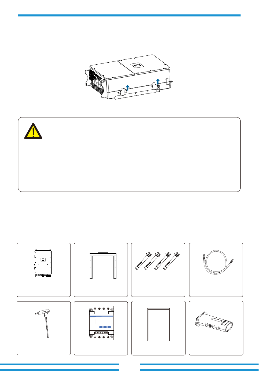
2.5 Product handling requirements
CAUTION:
Improper handling may cause personal injury!
· Arrange an appropriate number of personnel to carry the inverter according to
its weight, and installation personnel should wear protective equipment such
as anti-impact shoes and gloves.
· Placing the inverter directly on a hard ground may cause damage to its metal
enclosure. Protective materials such as sponge pad or foam cushion should be
placed underneath the inverter.
· Move the inverter by one or two people or by using a proper transport tool.
· Move the inverter by holding the handles on it. Do not move the inverter by
holding the terminals.
Lift the inverter out of the packaging box and transport it to the designated installation location.
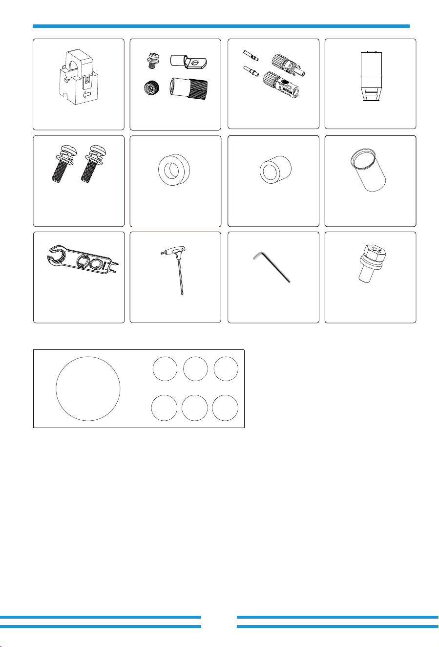
Sensor Clamp
x 3
- 07 -
3.2 Mounting instructions
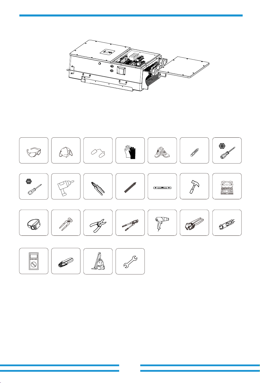
Installation Precaution
This Hybrid inverter is designed for outdoor use(IP��), Please make sure the installation site
meets below conditions:
Excessive heat buildup, heavy rainfall or water pooling, can impact the performance and
longevity of the inverter. Before connecting all wires, please take off the metal cover by
removing screws as shown below:
· Not in direct sunlight, rain exposure, snow laying up during installation and operation.
· Not in areas where highly flammable materials are stored.
· Not in potential explosive areas.
· Not directly expose to the cold air to avoid condensation inside the inverter casing .
· Not near the television Antenna or antenna cable.
· Not higher than altitude of about ���� meters above sea level.
· Not in environment of precipitation or humidity(>��%)
DC+/DC- Plug connectors
including metal terminal
xN
Battery Plug connectors
accessories x4
T-type wrench(8mm)
x1
Stainless steel mounting
screws M4*12 x8
4,5,6
Magnetic ring for CT x3
(31×29×19 mm)
Magnetic ring for
commuication cable of
BMS and Meterx3
(23×33×15 mm)
1,2,3
Matching Resistor x1
Solar Photovoltaic
Connector Special
Spanner x1
Wire Ferrules x14
1,2,3 : 23×33×15 mm
4,5,6 : 31×29×19mm
Packing box of magnetic ring
1 2
3
4
5
6
L-type Hexagon wrench
x1
M6×14
xN
- 08 -
Considering the following points before selecting where to install:
· Please select a vertical wall with load-bearing capacity for installation, suitable for installation
on concrete or other non-flammable surfaces, installation as follows.
· Install this inverter at eye level in order to allow the LCD display to be read at all times.
· The ambient temperature is recommeded to be between -��~��℃ to ensure optimal operation.
· Be sure to keep enough distance between other objects and the inverter surfaces as shown in the
diagram to guarantee sufficient heat dissipation and have enough space for removing wires.
Installations Tools
Installation tools can refer to the following recommended ones. Also, use other auxiliary tools
on site.
Protective goggles EarplugsAnti-dust mask Work gloves Utlity Knife Slotted screwdriver
Cross screwdriver
Work shoes
Percussion drill
Anti-static wrist strap
Wire cutter
Wire stripper
Hydraulic pliers
Heat gun
Crimping tool�-�mm²
Solar connector
wrench
Pliers
Marker
Level
Rubber hammer socket wrenches set
Multimeter ≥���� Vdc
RJ�� crimping plier
Cleaner
Spanner
- 09 -
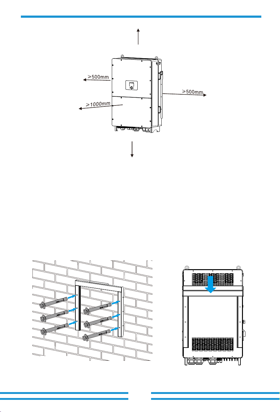
For a proper ventilation of the inverter and avoid overheating, allow a clearance of approximately
�� cm around the inverter and at least ��� cm to the front as it can be seen at the picture below.
Mounting the inverter
Remember that this inverter is heavy! Please be careful when lifting out from the package.
Choose the recommend drill head(as shown in below pic) to drill � holes on the wall,
��-��mm deep.
�. Use a proper hammer to fit the expansion bolt into the holes.
�. Screw out the nuts of the expansion bolts, align the holes of the mounting bracket with the �
expansion bolts, and then push in the mounting bracket, tighten the nuts of expansion bolts.
�. Mount the inverter on the mounting bracket and use screws to fix the inverter with mounting
bracket.
≥500mm
≥500mm
Inverter Moun�ng bracket installa�on
Size: M12×60
- 10 -
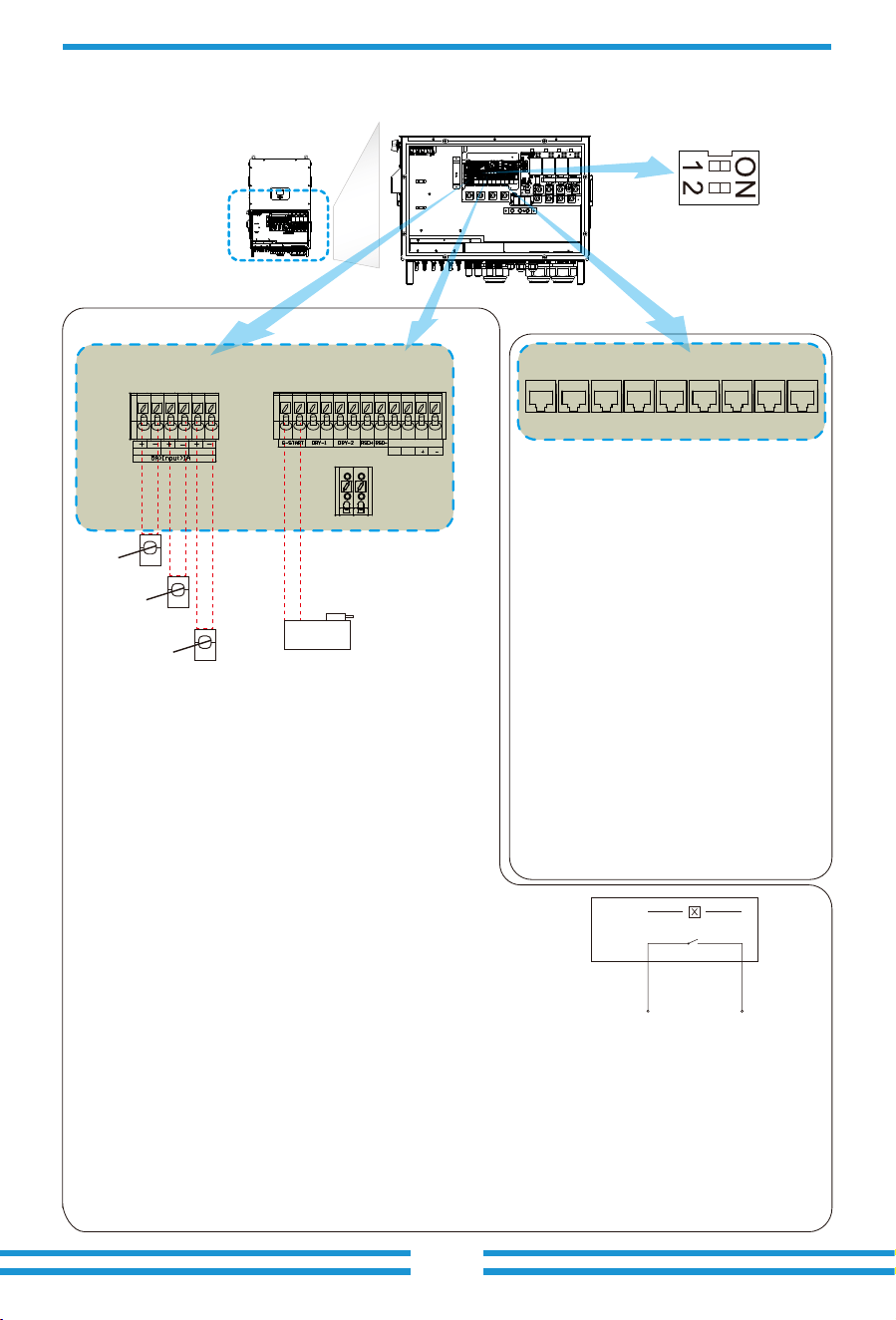
1 2 3 4 5 6 1 2 3 4 5 6 7 8 9 10 1112
Meter: for energy meter communication.
Parallel_1: Parallel communication
port 1.
Parallel_2: Parallel communication
port 2 . (Parallel A and B are
same and have no particular orders)
CAN: reserved.
DRM: Logic interface for AS/
NZS 4777.2:2020.
BMS1: BMS port for battery
communication port 1.
BMS2: BMS port for battery
communication port 2.
RS485: RS485 port.
LAN1:Used for Modbus TCP
communication with the host
computer.
CT -L2
CT -L3
CT -L1
Gen start-up
N/O Relay
Parallel_1 Parallel_2Meter CAN DRM BMS1 BMS2 RS485 LAN1
3.3 Func�on port defini�on
CN1 CN2
Inverter
CT-L1 CT-L2 CT-L3
SHUT DOWN
B B
CN1:
CT-L1 (1,2): current transformer (CT-L1) for"zero
export Partial Backup"mode clamps on L1
when in three phase system.
CT-L2 (3,4): current transformer (CT-L2) for"zero
export Partial Backup"mode clamps on L2
when in three phase system.
CT-L3 (5,6): current transformer (CT-L3) for"zero
export Partial Backup"mode clamps on L3
when in three phase system.
If the secondary current of CT are within the range of
1A-5A, use terminals 1-6.
CN2:
G-start (1,2): dry contact signal for startup the diesel generator.
When the "GEN signal" is active, the open contact (GS) will
switch on (no voltage output).
DRY-1 (3,4): reserved.
DRY-2 (5,6): reserved.
RSD+,RSD- (7,8): When battery is connected and the
inverter is in "ON" status, it will provide 12Vdc.
SHUT DOWN (9,10,11,12): if the terminal "B" & "B" (9&10) is short-circuited with wire
connection, or there’s 12Vdc input at the terminal "+ "& "- " (11&12), the inverter will
give alarm (F22) and shutdown immediately.
DI+,DI-: According to "Article 14a of the German Energy Industry Act (EnWG)" (2024) The
Energy Industry Act, The digital interface DI of the hybrid inverters can receive an external
control signal to reduce the power drawn from the grid to less than 4.2kW. When the signal
disappears, the inverter can return to its previous operating state.
DIP switch:For
communication setting
of parallel system.
DRM: It is used to accept the
external input signal(Digital input).
More details please refer to the P57.
DI+ DI-
GS (diesel generator startup signal)
relay
coil
open
contact
G S
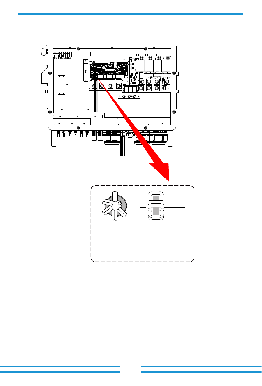
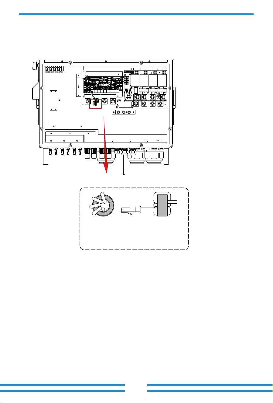
Thread the end of the CT's wires through
the magnetic ring � and wrap the wires
around it five lap. Fix the magnetic ring
near the wiring terminals, as shown in the
above diagram. Repeat this operation for
the other two CTs.
- 11 -
4 6
5
- 12 -
3.4 Battery connection
For safe operation and compliance, a separate DC over-current protector or disconnect device is
required between the battery and the inverter. In certain applications, a disconnect switch may
not be necessary, but it is always essential to have DC overcurrent protection in place. Refer to
the typical amperage in the page 28 for the required fuse or circuit breaker size.
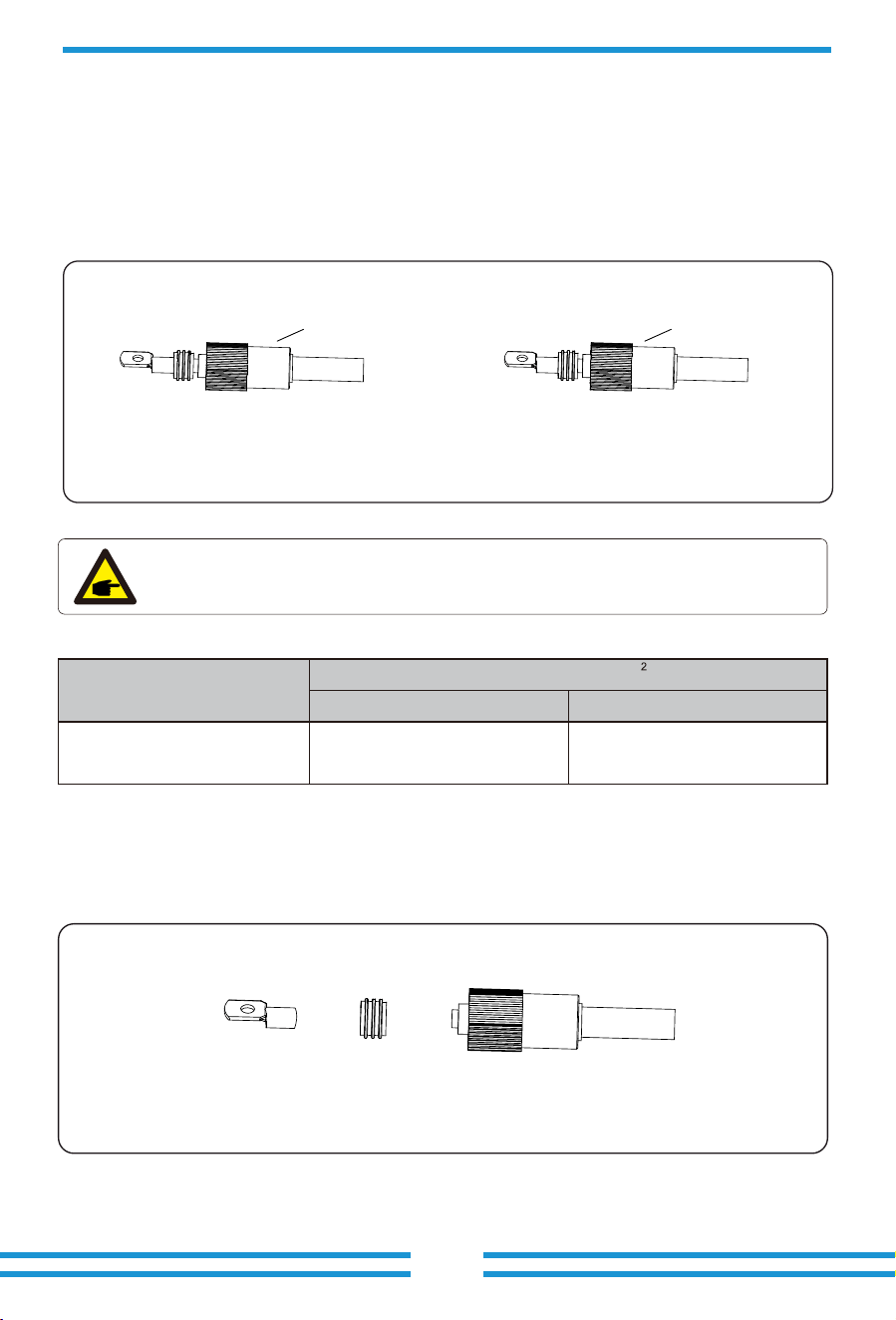
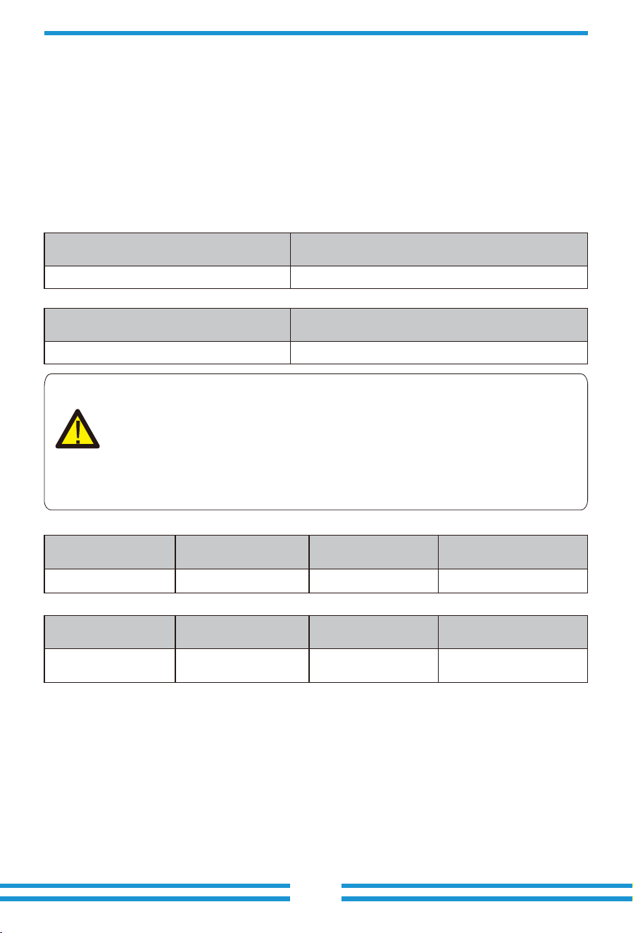
Pic 3.1 BAT+ plug connector
Pic 3.2 BAT- plug connector
Orange
Safety Hint:
Please use approved DC cable for battery system.
Model
Range Recommended value
Cross section(mm )
SUN-100K-SG02HP3-EU-GM8/
SUN-100/125K-SG02HP3-EU-GM10
2AWG
25mm
2
Chart 3-2
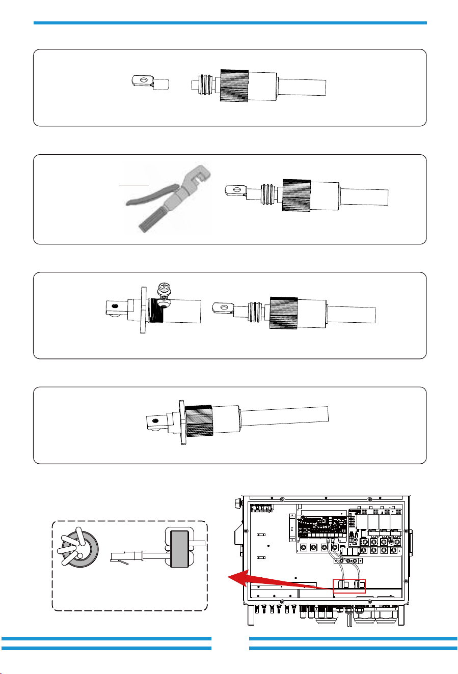
The steps to assemble the battery plug connectors are listed as follows:
a) Pass the cable through the terminal, as shown in Pic 3.3.
Pic 3.3
Black
- 13 -
b) Put on the rubber ring, as shown in Pic 3.4.
Pic 3.4
d) Fasten terminal with a bolt, as shown in Pic 3.6.
Pic 3.6
e) Fasten the terminal with outer cover, as shown in Pic 3.7.
Pic 3.7
c) Crimp the metal terminal, as shown in Pic 3.5.
Pic 3.5
Hydraulic pliers
BMS connection
Thread the BMS communication cable
through the magnetic ring 1,2 and wrap
it around the magnetic ring four times.
1,2
- 14 -
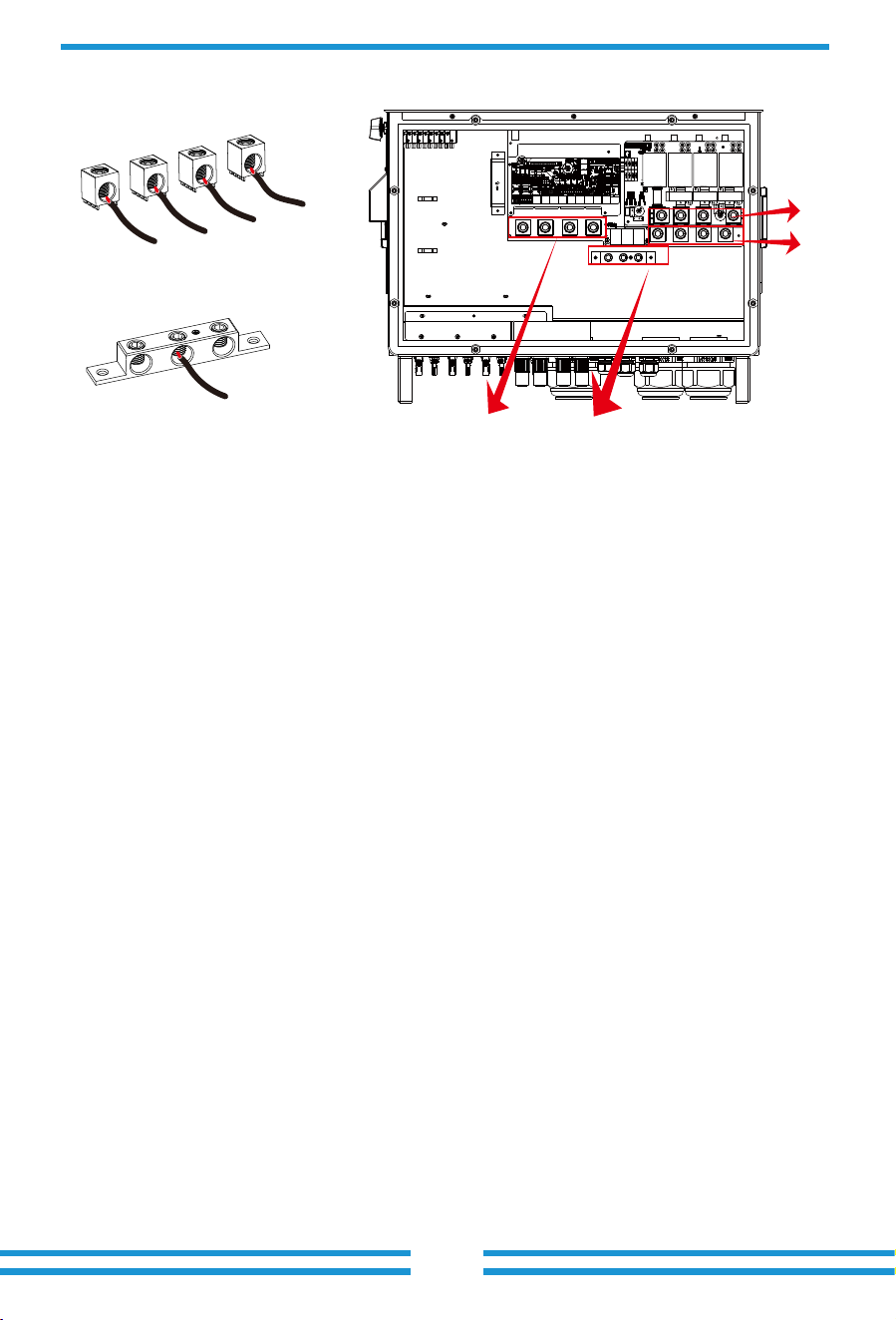
3.5 Grid connection and backup load connection
· Before connecting to the grid, a separate AC breaker must be installed between the inverter
and the grid, and also between the backup load and the inverter.This will ensure the inverter
can be securely disconnected during maintenance and fully protected from over current.Check
the recommended values in the following tables according to local regulations in each country.
The recommended specifications for AC breakers here are based on the Max.Continuous AC
passthrough current of inverter, you can also choose the AC breaker of backup side according
to the actual total operating current of all the backup loads.
· There are three terminal blocks with "Grid" "Load"and "GEN" markings. Please do not misconnect
input and output connectors.
Grid connection and backup load connection (Copper wires) (bypass)
Model Wire Size
250kcmil
Cross section(mm )
2
120
Torque value(max)
33.9 N.m
Grid connection and backup load connection (Copper wires)
Note:
In final installation,breaker certified according to IEC 60947-1 and IEC 60947-2
shall be installed with the equipment.
Model
Recommended
AC breaker
320A
AC Breaker for backup load
AC Breaker for grid
All wiring must be performed by a qualified personnel.It is very important for
system safety and efficient operation to use appropriate cable for AC input
connection. To reduce risk of injury, please use the proper recommended cable
as below. There are two tables below, the first table recommends cable specififi-
cations based on bypass current(Max.Continuous AC passthrough), and the
second table is based on Max.AC output current.
Model
Recommended
AC breaker
320A
1. Before making Grid, load and Gen port connection, be sure to turn off AC breaker or
disconnector first.
2. Strip the insulation of AC wires by about 10mm, insert AC wires according to polarities indicated
on the terminal block and tighten the terminals. Be sure to connect corresponding N wires and PE
wires to related terminals as well.
Please follow below steps to implement Grid, load and Gen port connection:
Chart 3-3 Recommended Size for AC wires
Model Wire Size
250kcmil
Cross section(mm )
2
120
Torque value(max)
33.9 N.m
SUN-100K-SG02HP3-EU-GM8
SUN-100/125K-SG02HP3-EU-GM10
SUN-100K-SG02HP3-EU-GM8
SUN-100/125K-SG02HP3-EU-GM10
SUN-100K-SG02HP3-EU-GM8
SUN-100/125K-SG02HP3-EU-GM10
SUN-100K-SG02HP3-EU-GM8
SUN-100/125K-SG02HP3-EU-GM10
- 15 -
E-BAR
N
L1
L2
L3
PE
GRID
LOAD
E-BAR
GEN
3.6 PV Connection
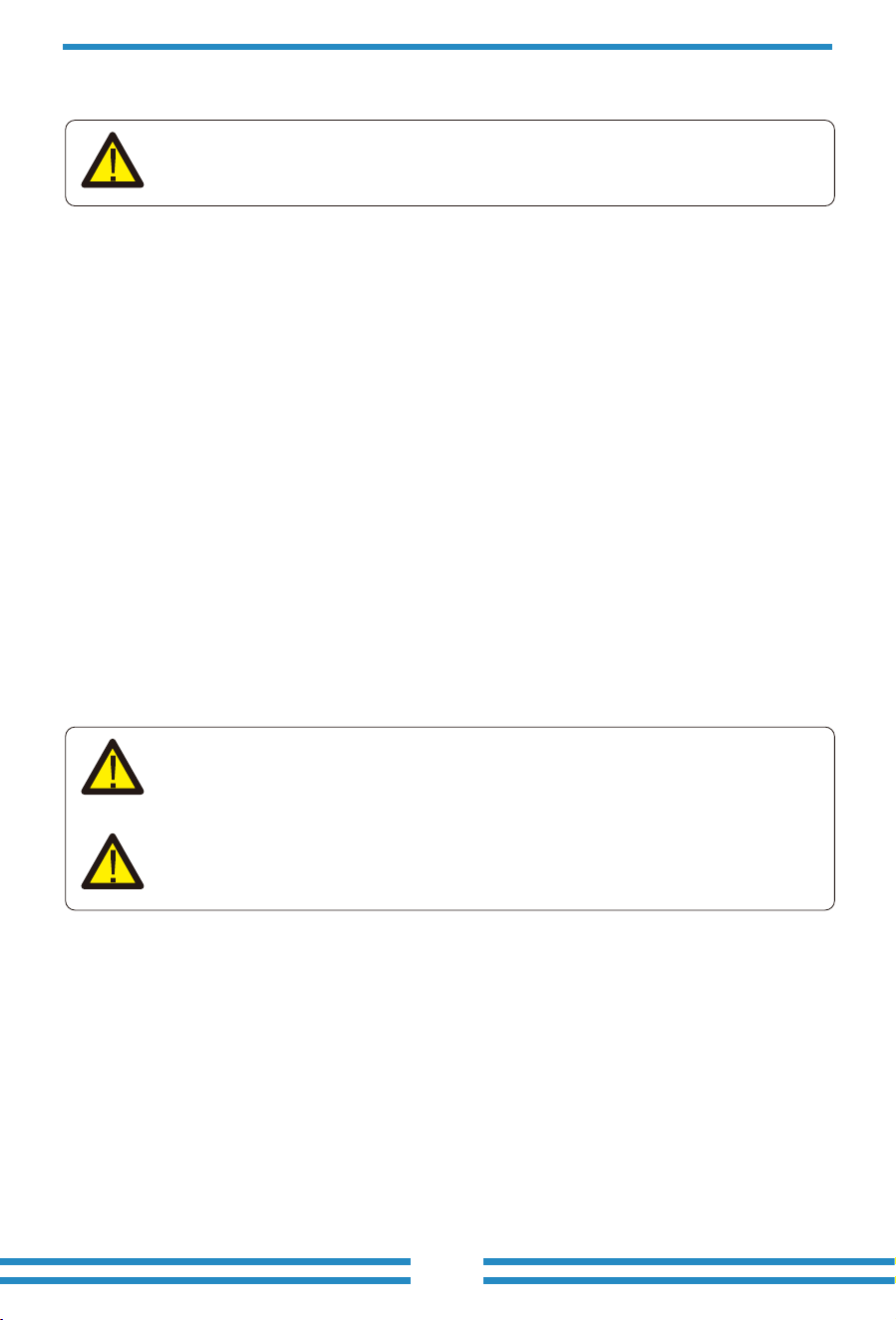
3. Make sure all the wires are securely and completely connected.
Before connecting to PV modules, please install a separately DC circuit breaker between
inverter and PV modules. It is very important for system safety and efficient operation to
use appropriate cable for PV module connection.
Be sure that AC power source is disconnected before attempting to wire it to the
unit.
To avoid any malfunction, do not connect any PV modules with possible leakage
current to the inverter. For example, grounded PV modules will cause leakage
current to the inverter. When using PV modules, please ensure the PV+ & PV-
of solar panel is not connected to the system ground bar.
It is requested to use PV junction box with surge protection. Otherwise, it will
cause damage on inverter when lightning occurs on PV modules.
4. Some appliances, such as air conditioners and refrigerators, may need a time delay before
recconneting them after a power outage. This delay allows the refrigerant gas to stabilize and
prevents potential damage. Check if your appliance has a built-in time-delay function before
connecting it to our inverter. Examples of appliances that may require a delay include:
Air conditioners: Balancing refrigerant gas.
Refrigerators: Stabilizing the compressor.
Freezers: Allowing the cooling system to balance.
Heat pumps: Protecting against power fluctuations.
This inverter will protect your appliances by triggering an overload fault if no time delay is
present. However, internal damage may still occur. Refer to the manufacturer's documenta-
tion for specific time-delay requirements.
- 16 -
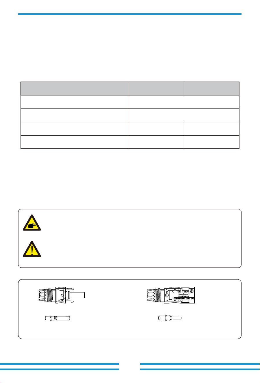
3.6.1 PV Module Selection:
3.6.2 PV Module Wire Connection:
When selecting proper PV modules, please be sure to consider below parameters:
1) Open circuit Voltage (Voc) of PV modules can not exceed max.PV Input Voltage of
inverter.
2) Open circuit Voltage (Voc) of PV modules should be higher than min.PV Input Voltage of inverter.
3) The PV modules used to connected to this inverter shall be Class A rating certified according
to lEC 61730.
- 17 -
1. Switch the Grid Supply Main Switch(AC)OFF.
2. Switch the DC lsolator OFF.
3. Assemble PV input connectors to the inverter.
Safety Hint:
Before connecting to inverter, please make sure that the open circuit voltage of
PV strings haven't exceeded the max.PV input voltage of the inverter.
Safety Hint:
Before connection, please make sure the polarity of PV array matches the
"DC+" and "DC-" symbols.
Pic 5.1 DC+ male connector
Pic 5.2 DC- female connector
Chart 3-5
PV Input Voltage
Inverter Model
PV Array MPPT Voltage Range
No. of MPP Trackers
No. of Strings MPP Tracker
650V (180V-1000V)
150V-850V
2+2+2+2+2+2+2+2+2+2
10
2+2+2+2+2+2+2+2
8
SUN-100/125K-SG02HP3-EU-GM10SUN-100K-SG02HP3-EU-GM8
- 18 -
Safety Hint:
Please use approved DC cable for PV system.
Cable type
Range Recommended value
Cross section(mm )
Industry generic PV cable
(model: PV1-F)
2.5-4
(12-10AWG)
2.5(12AWG)
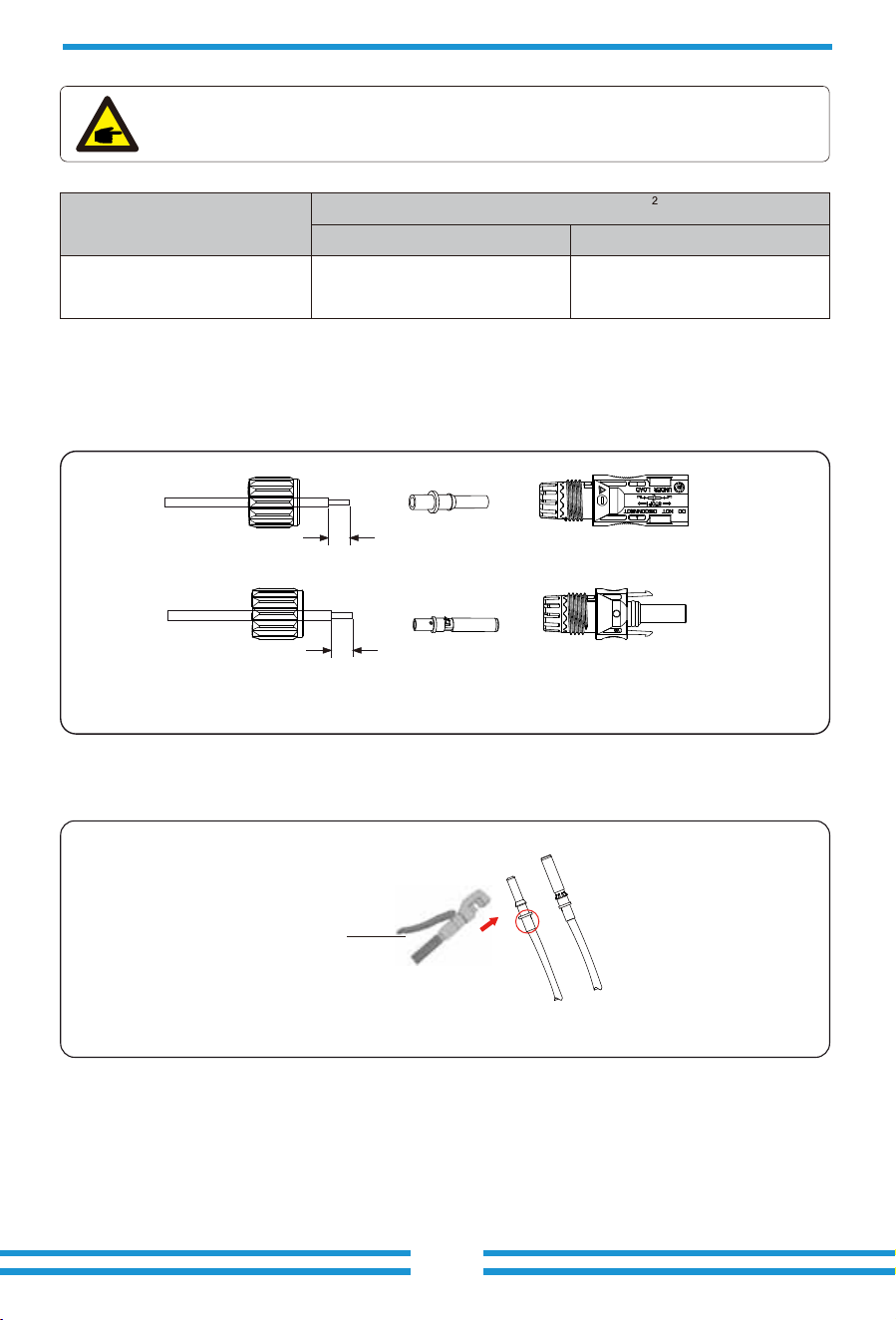
The steps to assemble the PV connectors are listed as follows:
a) Strip the insulation of the PV wire by 7 mm, disassemble the cap nut of the connetctor,
thread one PV wire through the cap nut of the connector (see Pic 5.3). Repeat this operation
with all the PV wires, paying special attention to the polarity of the connector.
b) Crimping metal terminals with crimping pliers , as shown in Pic 5.4.
c) Insert the contact pin to the top part of the connector and completely tighten the cap nut to
the top part of the connector, as shown in Pic 5.5.
Pic 5.3 Disassemble the connector cap nut
Pic 5.4 Crimp the contact pin to the wire
Chart 3-6
7mm
7mm
Hydraulic pliers
-19 -
Pic 5.5 connector with cap nut screwed on
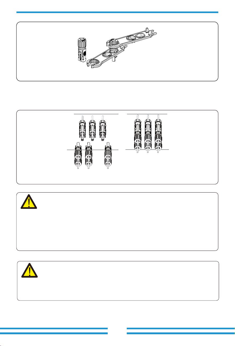
d) Finally insert the PV connectors into the positive and negative PV inputs of the inverter, as
shown in Pic 5.6.
Pic 5.6 DC input connection
Warning:
Warning:
Please use its own DC power connector from the inverter accessories. Do not
interconnect the connectors of different manufacturers. The Isc current of PV
modules should not exceed the Max.PV Isc current of this inverter. If exceeds,
it may damage the inverter and is not covered by Deye's warranty.
When operating the PV strings, be aware that sunlight exposure can generate high
voltages in the PV strings. Avoid contact with exposed electrical connecters or
terminals to prevent electrical shock or injury. For safety, it is best to operate the
PV strings at night or when PV modules are not exposed to sunlight. If daytime
operation is necessary, cover the PV modules to minimize sunlight exposure and
prevent high voltage generation. Remember to turn off the DC breaker or switch
before performing any maintenance or adjustments. Do not turn off the DC
breaker or switch when high voltage or high current is present to avoid damage or
hazards. Prioritize personal safety.
- 20 -
1 2 3 4 5 6
CT-L1 CT-L2 CT-L3
White wire
Black wire
CT
Arrow pointing
to inverter
Grid
N
PE
L1
L2
L3
CT1
CT2
CT3
Inverter
GRID
N
L1
L2
L3
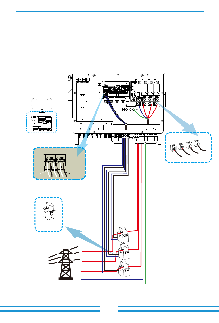
3.7 Meter or CT installation
3.7.1 CT connection
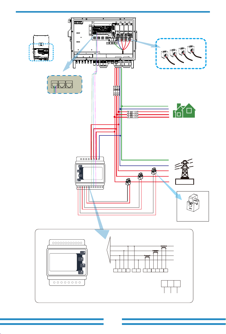
There are three selectable installation methods to measure the power consumption or to ensure zero power
export to grid. The default installation method is to use the CTs(300A/5A) that come with the packaging
box. When the distance between the AC distribution box and the hybrid inverter exceeds 10 meters, which
means that the wire length of the CT needs to exceed 10 meters, it is recommended to use a smart meter
instead of three CTs. In addition, in a parallel system, if the current to be measured is greater than 300 A, the
default three CTs also need to be replaced with smart meters or larger CTs. Please contact the Deye support
team to confirm which specification of CT or smart meter to use.

- 21 -
*Note:When taking power from the utility grid, if the grid power displayed
on the LCD screen is indeed negative, please adjust the installation direction
of the CTs.Please refer to Chapter 3.10 for the position to be clamped.
Due to Max. Continuous AC Passthrough (grid to load) is 200A,so only transformer meter which can measure
higher current is recommended to be installed.The smart meter brands that Deye inverters have been
matched with include CHINT and Eastron, The recommended models here are not all compatible models, It
is recommended to purchase smart meter from authorized distributors of Deye, otherwise it may not be able
to be used due to communication mismatch. The definition of the "Meter" port can be found in the Appendix
part which is in the end of this user manual.
3.7.2 Meter connection with CTs
Note: the arrow direc�on
towards the inverter
- 23 -
Black line
Black line
Black line
Red line
Red line
Red line
GRID
Parallel_1 Parallel_2Meter
Inverter
L1
L2
L3
N
PE
Grid
AC Breaker
AC Breaker
Home Load
L1
L3
N
PE
L2
CT1
CT2
CT3
Eastron meter
Eastron SDM630MCT
1 2 3 4 5 6
L1
L2
L3
N
P1P2
S1S2
P2 P1
S1S 2
P1P2
S1
S2
3 PHASE 4 WIRE
15 16
17 18
19 20
Grid voltage
sampling
Auxiliary
power supply
Current inputs
RS 485
RS 485 A RS 485 B
14 13 12
GND
1 2 3 4 5 6 7 8
9 10 11 12 13 14 15 16 17 18 19 20
P
M
E
U/I
ESC
Eastron
meter
NA LA L1 L2 L3 N
S1 S2 S1 S2 S1 S2
1 2 3 4 5 6 7 8
9 10 11 12 13 14 15 16 17 18 19 20
P
M
E
U/I
ESC
Eastron
RS485A
RS485B
GND
N
L1
L2
L3
- 24 -
Meter connection
3
Thread the meter communication cable
through the magnetic ring 3 and wrap
it around the magnetic ring four times.
- 25 -
3.9 Data logger connection
For the configuration of data logger, please refer to the user manual of data logger. Wi-Fi logger is
not the only option, If the installation location does not have Wi-Fi signal or the signal is weak,
you can also choose a data logger that communicates via other interfaces.
The conductor should be made of the same metal as the phase conductors.
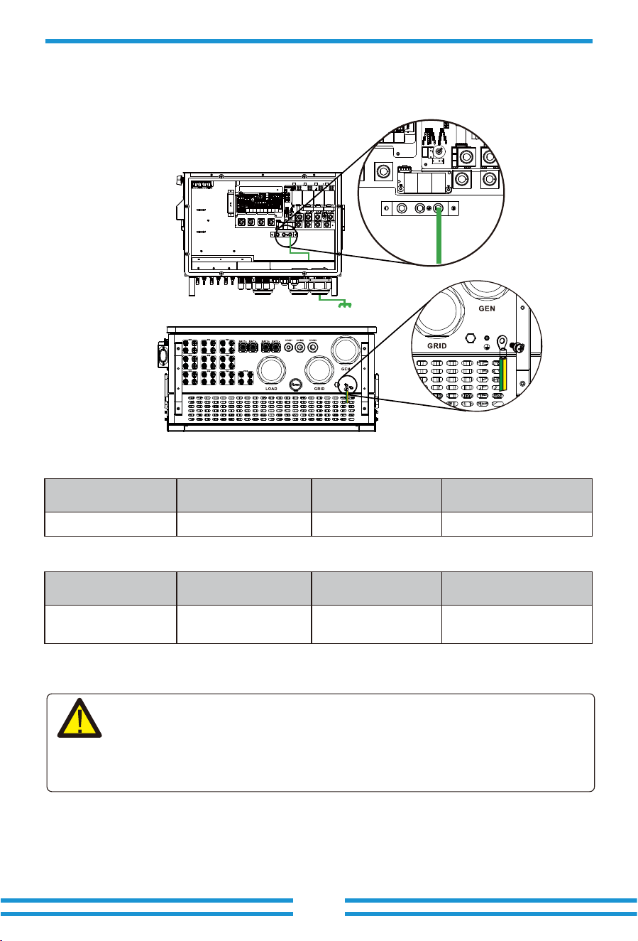
3.8 Earth Connection(mandatory)
The PE wires of AC cables( if have) shall connect to the E-Bar inside the junction box of the inverter,
and the ground hole on the shell of the inverter shall be connected to the external groud plate.
Earth Connection (Copper wires) (bypass)
Model Wire Size
3/0AWG
Cross section(mm )
2
70
Torque value(max)
31 N.m
Earth Connection (Copper wires)
Warning:
Inverter has built-in leakage current detection circuit,The type A RCD can be connected to
the inverter for protection according to the local laws and regulations.If an external leakage
current protection device is connected to the grid port of inverter, please refer to section
3.11, its operating current must be equal to 10mA/KVA or higher, for this series of inverter it
should be 1250mA or higher, otherwise inverter may not work properly.
Model Wire Size
3/0AWG
Cross section(mm )
70
Torque value(max)
31 N.m
2
SUN-100K-SG02HP3-EU-GM8
SUN-100/125K-SG02HP3-EU-GM10
SUN-100K-SG02HP3-EU-GM8
SUN-100/125K-SG02HP3-EU-GM10
- 26 -
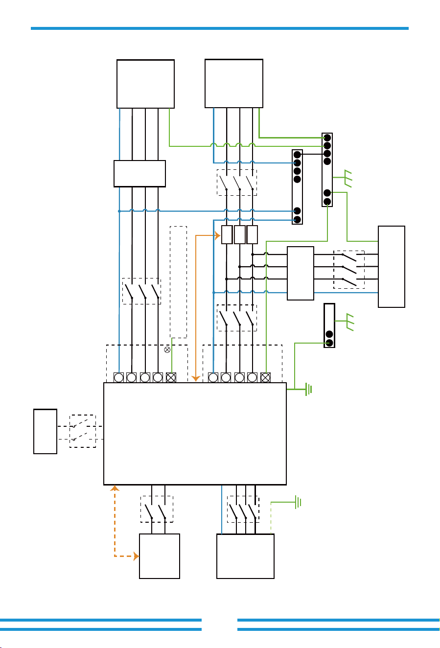
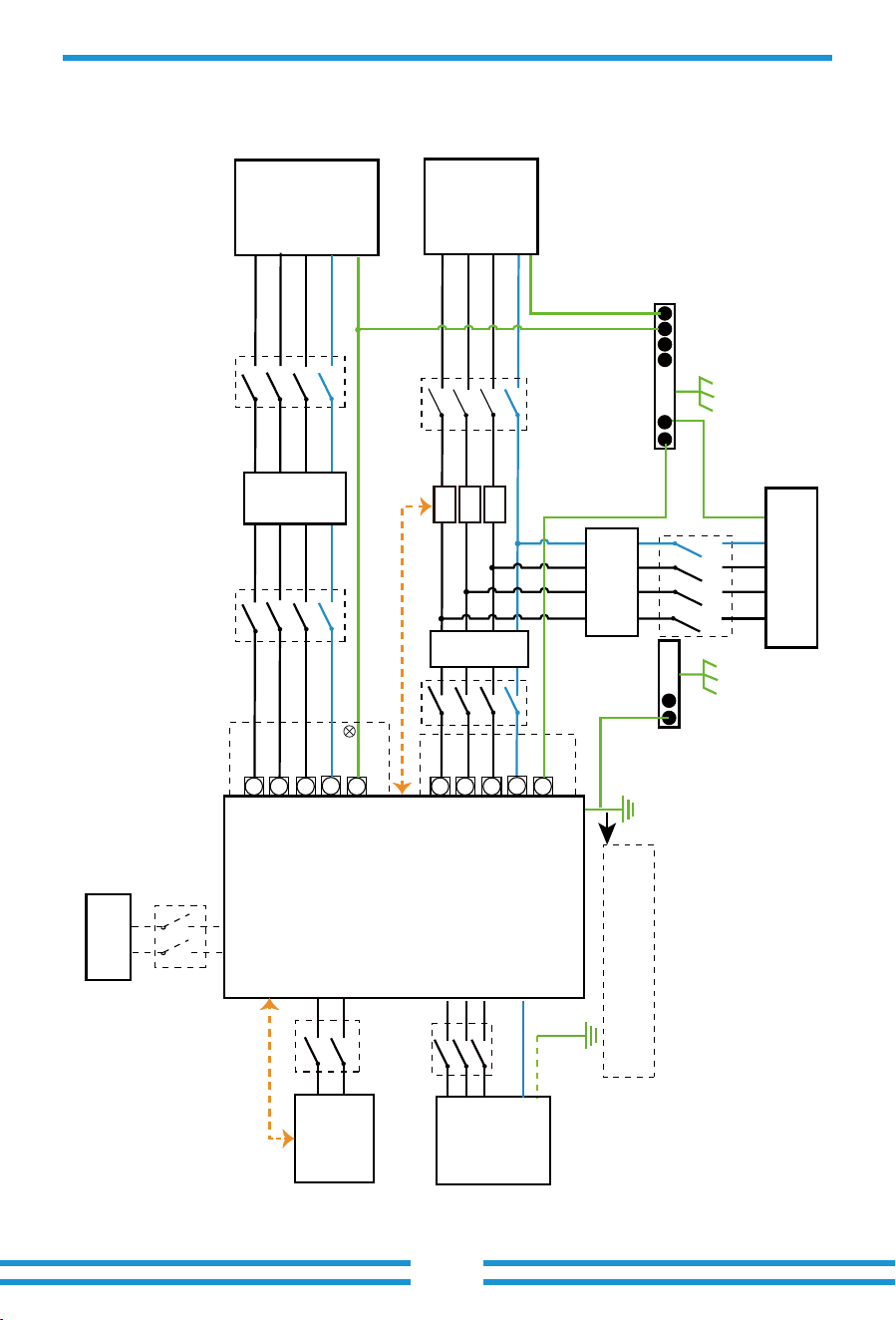
3.10 Wiring diagram with neutral line grounded
This diagram is an example for an application that neutral connects with the
PE in a distribution box.
For countries such as Australia, New Zealand, etc., please follow
local wiring regulations!
E-BAR
GEN
PORT
Load
CT
PE
AC Breaker
L1 L1
N N
L2
Load
PE or
L2
L3
L3
AC Breaker AC Breaker
L1
L1
L1
N
N
N
L2
L2
Grid
PE
L2
L3
PE
PE
L3
L1
N
L2
PE
L3
L3
AC Breaker
Hybrid Inverter
CT1
CT2
CT3
RCD
Home Loads
E-BAR
Grid
Battery
BMS
DC Breaker
PV
DC Breaker
Do not connect this terminal when the neutral
wire and PE wire are connected together.
Inverter case grounding
N-BAR
E-N
Link
RCD
- 27-
3.11 Wiring diagram with neutral line ungrounded
This diagram is an example for an application in which neutral is separated from the
PE in the distribution box.
For countries such as China, Germany,the Czech Republic, Italy, etc., please follow local
wiring reguations!
E-BAR
Backup
Loads
CT
PE
L2 L2
L1 L1
L3
Backup
PE or
L3
N
PE
N
L2
L2
L2
L1
L1
L1
L3
L3
On-Grid
PE
L3
N
PE
N
N
Hybrid Inverter
CT1
CT2
CT3
RCD
Home Loads
RCD
E-BAR
Grid
Battery
BMS
Distribution box
1250mA RCD (Recommended)
RCD
DC Breaker
Grouding screw hole in the
lower right corner
GEN
PORT
L1
N
L2
PE
L3
AC Breaker
PV
DC Breaker
- 28 -
L wireCAN N wire PE wire
BMS1 BMS2
Grid
Backup Load
Inverter
①DC
Breaker
②AC Breaker
③AC Breaker
④AC Breaker
Battery pack
Home Load
L1
L1
L2
L2
L3
L3
N
N
PE
PE
L1
L2
L3
N
PE
Ground
CT1
CT2
CT3
① DC Breaker for battery
SUN-100K-SG02HP3-EU-GM8: 125A DC breaker
SUN-100K-SG02HP3-EU-GM10: 125A DC breaker
SUN-125K-SG02HP3-EU-GM10: 125A DC breaker
② AC Breaker for backup load
SUN-100K-SG02HP3-EU-GM8: 320A AC breaker
SUN-100K-SG02HP3-EU-GM10: 320A AC breaker
SUN-125K-SG02HP3-EU-GM10: 320A AC breaker
③ AC Breaker for grid
SUN-100K-SG02HP3-EU-GM8: 320A AC breaker
SUN-100K-SG02HP3-EU-GM10: 320A AC breaker
SUN-125K-SG02HP3-EU-GM10: 320A AC breaker
④AC Breaker for home load
Depends on household loads
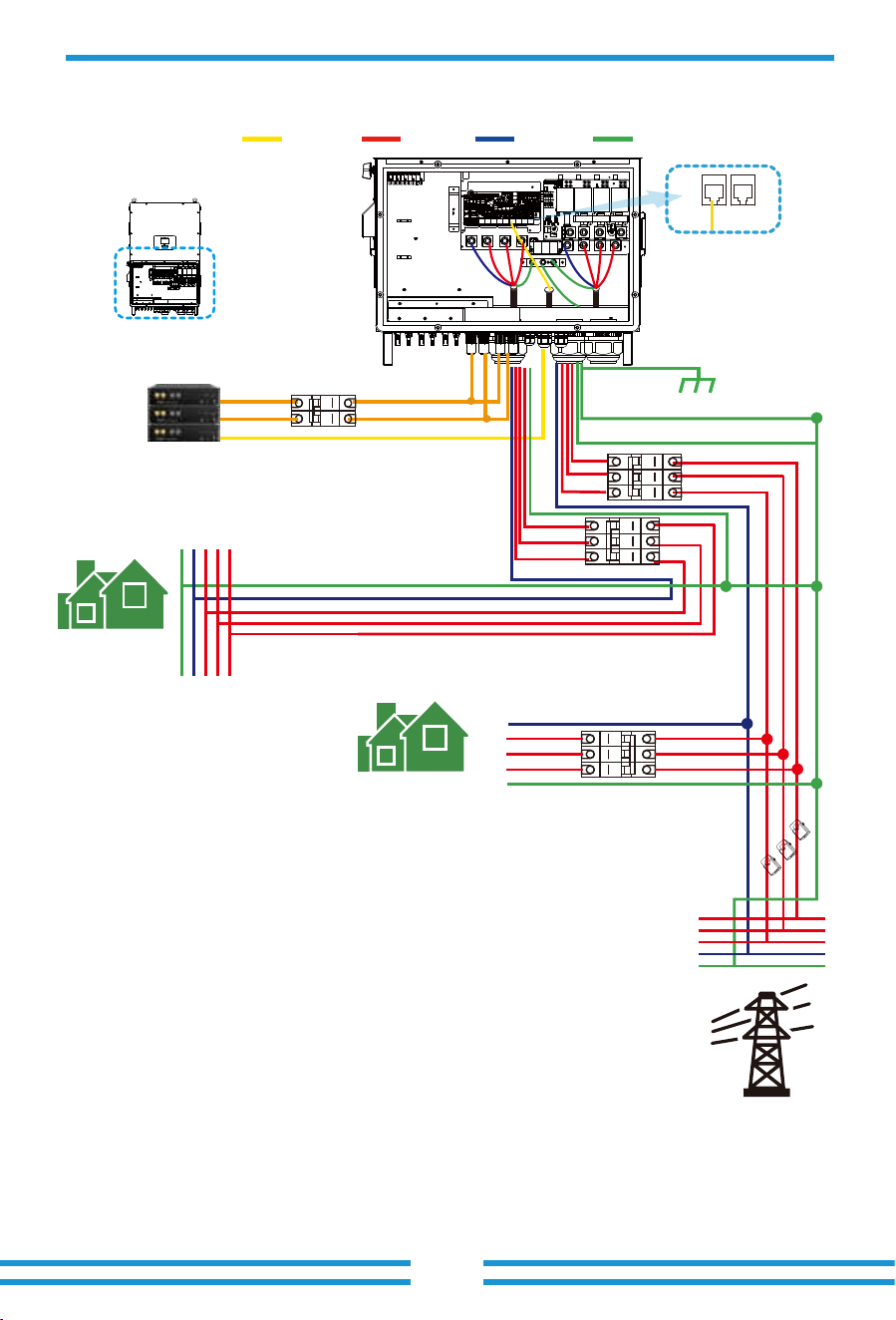
3.12 Typical application diagram of on-grid system
BMS1 BMS2
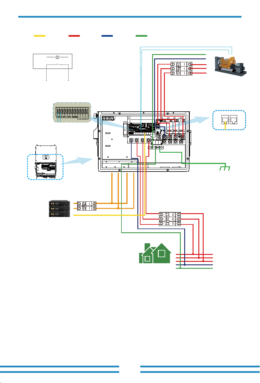
3.13 Typical application diagram of diesel generator
- 29 -
L wireCAN N wire PE wire
①DC
Breaker
Battery pack
Backup Load
L3
L2
L1
N
PE
Generator
GS (diesel generator startup signal)
relay
coil
open
contact
G S
G-start (1,2): dry contact signal for startup
the
diesel generator.
Remotely control signal line
Inverter
③AC Breaker
②AC
Breaker
L3
L2
L1
N
PE
1 2 3 4 5 6 7 8 9 10 1112
SHUT DOWN
B B
Ground
① DC Breaker for battery
SUN-100K-SG02HP3-EU-GM8: 125A DC breaker
SUN-100K-SG02HP3-EU-GM10: 125A DC breaker
SUN-125K-SG02HP3-EU-GM10: 125A DC breaker
② AC Breaker for backup load
SUN-100K-SG02HP3-EU-GM8: 320A AC breaker
SUN-100K-SG02HP3-EU-GM10: 320A AC breaker
SUN-125K-SG02HP3-EU-GM10: 320A AC breaker
③ AC Breaker for Generator port
SUN-100K-SG02HP3-EU-GM8: 320A AC breaker
SUN-100K-SG02HP3-EU-GM10: 320A AC breaker
SUN-125K-SG02HP3-EU-GM10: 320A AC breaker
- 30 -
L wireCAN N wire PE wire
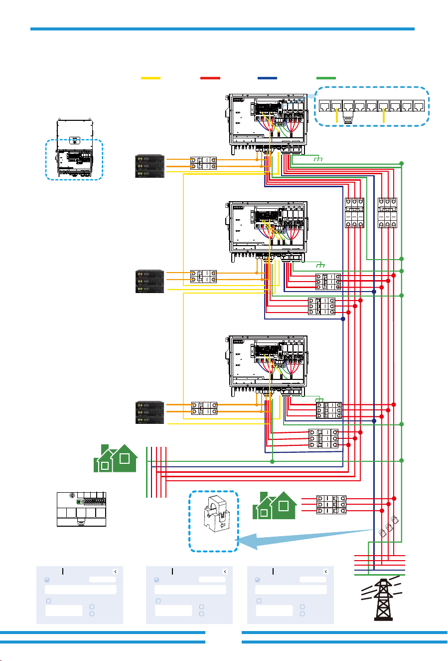
3.14 Three phase parallel connection diagram
Inverter
Master inverter Slave Inverter Slave Inverter
Grid
Backup Load
Inverter
No.3
(slave)
Inverter
No.2
(slave)
Inverter
No.1
(master)
⑩
⑤
②
③
Battery pack
Home Load
L1 L2 L3NPE
L1
L2
L3
N
PE
CT
Arrow point to inverter,
and connect CT's cables to
the master inverter.
⑧
Ground
Ground
Ground
Battery pack
①
Battery pack
CT1
CT2
CT3
Parallel_1 Parallel_2Meter CAN DRM BMS1 BMS2 RS485 LAN1
①②③ DC Breaker for battery
SUN-100K-SG02HP3-EU-GM8: 125A DC breaker
SUN-100K-SG02HP3-EU-GM10: 125A DC breaker
SUN-125K-SG02HP3-EU-GM10: 125A DC breaker
⑤⑦⑨ AC Breaker for backup load
SUN-100K-SG02HP3-EU-GM8: 320A AC breaker
SUN-100K-SG02HP3-EU-GM10: 320A AC breaker
SUN-125K-SG02HP3-EU-GM10: 320A AC breaker
④⑥⑧ AC Breaker for grid port
SUN-100K-SG02HP3-EU-GM8: 320A AC breaker
SUN-100K-SG02HP3-EU-GM10: 320A AC breaker
SUN-125K-SG02HP3-EU-GM10: 320A AC breaker
⑩ AC Breaker for home load
Depends on household loads
⑥
⑦
⑨
④
Note: For the parallel system, the lead-acid battery and 'No Batt' mode are not supported.
All inverters connected in parallel must be the same model. Please use lithium battery which
is on the "Deye Approved Battery list".
Each inverter should have its own separate battery set.
Ensure that the DIP switches of each
hybrid inverter in the parallel system
are switched to the OFF state.
Note: The idle parallel ports of the first and last inverters
need to be plugged in with matching resistors.
OFF
ON
Note: For the parallel system,
please choose the "Zero export Partial Backup " mode.
Only the master inverter needs to be
installed CT.
Advance
Multi-Inverter
Parallel
Ex_Meter for CT
Grid Tie Meter2
MPPT_Scan
Master 01
Meter Select
No Meter
Baud Rate
115200
Advance
Multi-Inverter
Parallel
Ex_Meter for CT
Grid Tie Meter2
MPPT_Scan
Slave 02
Meter Select
No Meter
Baud Rate
115200
Advance
Multi-Inverter
Parallel
Ex_Meter for CT
Grid Tie Meter2
MPPT_Scan
Slave 03
Meter Select
No Meter
Baud Rate
115200
4. OPERATION
4.1 Power ON/OFF
4.2 Operation and Display Panel
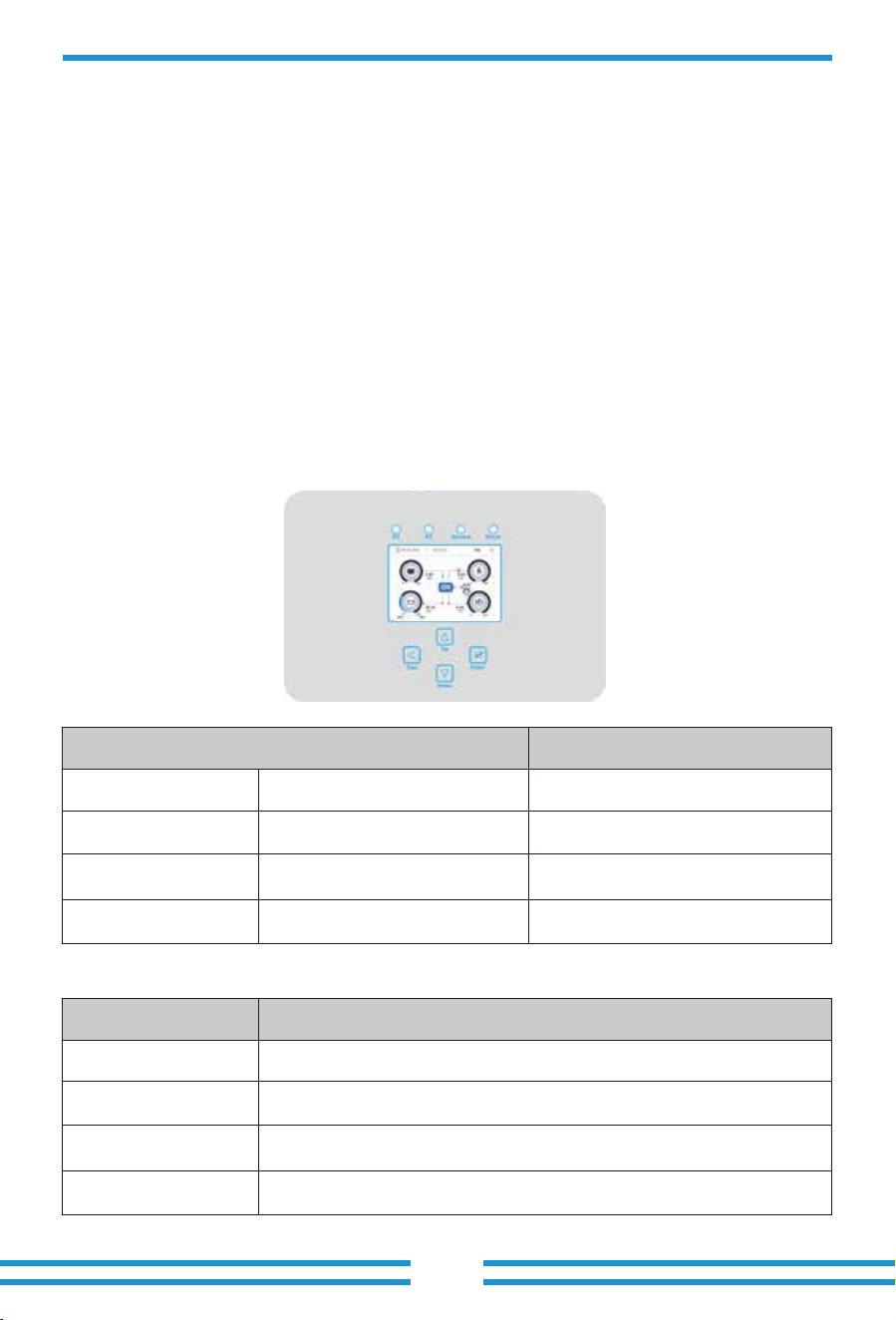
The operation and display panel, shown in below chart, is on the front panel of the inverter.
It includes four indicators, four function keys and a LCD display, indicating the operating status
and input/output power information.
Chart 4-1 LED indicators
LED Indicator
DC
AC
Normal
Alarm
Green led solid light
Green led solid light
Green led solid light
Red led solid light
PV Connection normal
Grid Connection normal
Inverter operating normal
Malfunction or warning
Messages
Chart 4-2 Function Buttons
Function Key
Esc
Up
Down
Enter
Description
To exit setting mode
To go to previous selection
To go to next selection
To confirm the selection
- 31 -
Once the system has been properly installed and the battery is connected to the inverter, follow
the steps below to turn on the inverter:
1. Turn all the breakers of the installation on.
2. Turn on the DC switches of the inverter and the power button of battery (If there is one battery
installed at the system), no matter the order.
3. Press the ON/OFF button (located on the left side of the inverter case) to turn on the inverter.
When a system connected to either PV or Grid (without battery) is switched on, the LCD will still
be lighted up displaying "OFF". In this situation, after switching ON/OFF button on, select "NO
batt" at the inverter settings to make the system work.
When turning off the inverter, please follow the following steps:
1. Turn off the AC breakers on Grid port, Load port and GEN port.
2. Press the ON/OFF button of hybrid inverter and turn off the DC breaker on battery side, then
turn off the power button of the battery.
3. Switch off the DC switches of the inverter.
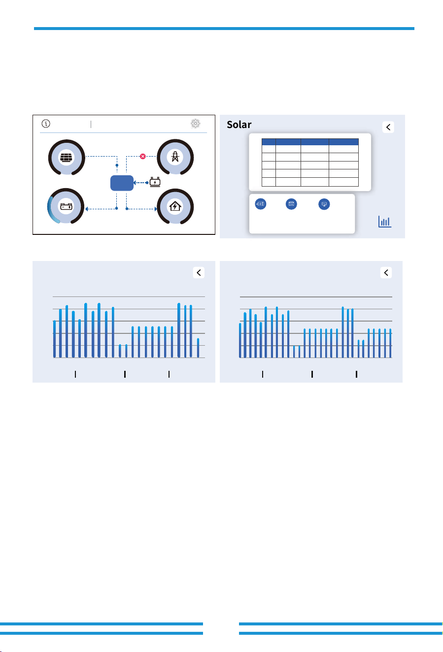
5.1 Main Screen
5. LCD Display Icons
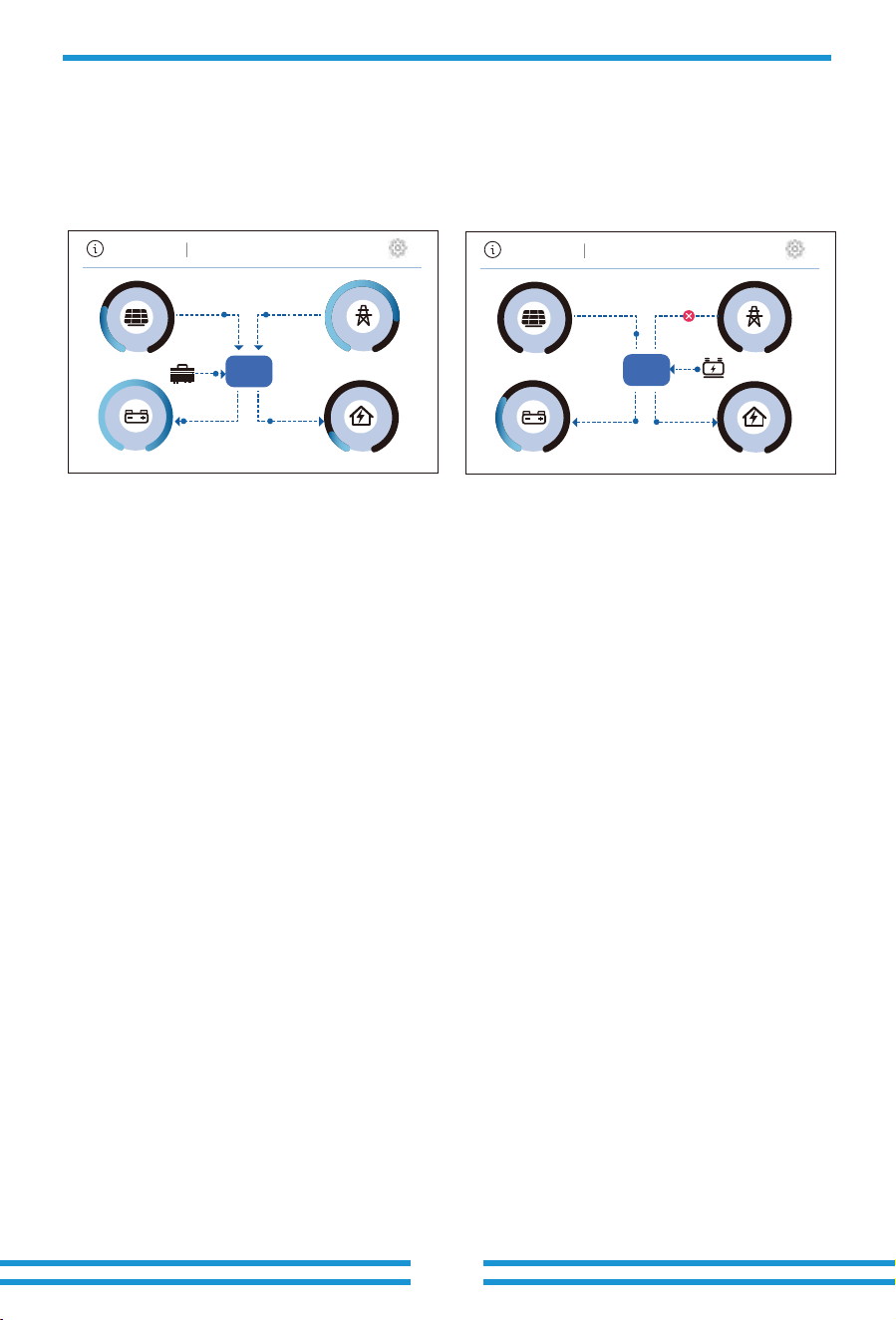
The LCD is touchscreen, below screen shows the overall information of the inverter.
- 32-
1.The icon at the center of the screen indicates whether the system is under normal operation
or not, displaying "ON" for normal status or displaying a code like "Comm./F01-F64" for
communication errors or other errors. Please refer to the Error code list of alarms and errors in
chapter 8 to find out solutions about the error.
2. On the left side of the top of the inverter's LCD screen is the local date and time. To ensure
the correct timestamp recording of historical data on the cloud server, please set it to the correct
local time or synchronize it with the cloud server during debugging.
3.Click the gear icon in the upper right corner of the inverter's LCD home screen to access the
inverter's 'Setting' menu page. In the Setting page, there are multiple interactive settings options.
4.The main screen includes the icons for PV(left up), grid (right up), on-grid inverter(slightly to the
left of center), generator(slightly to the right of center), load(right bottom), and battery
(left bottom). It also displays the energy flow direction by moving dots and arrows. When the power is
approaching to a high level, the color on the panels will change from black to blue, showing vividly
the system status on the main screen.
Some clarifications about the system status are as follows:
-PV power will always be positive.
-In single inverter system, load power will always be positive. In a parallel system, the load
power may be negative, which means that the other inverters supply power to this inverter
through the load port.
-A negative Grid power means energy being exported to the grid (sold), whereas positive means
energy being imported form the grid (purchased).
-Negative battery power means charging, positive means discharging.
The icon for the on-grid inverter, positioned slightly to the left of center, will only appear when
the conditions for connecting the on-grid inverter are met. Similarly, the generator icon located
slightly to the right of center becomes visible only after the generator connection conditions are
satisfied and the G-S dry contact is closed.
"Forced" is displayed between the inverter icon and the Load icon, indicating that the smart
load has been manually enabled by long-pressing the wave icon in the lower-left corner of the
Load detail page.
In contrast, if the smart load is activated automatically only when the battery SOC reaches the
ON threshold, "smart" will be shown between the two icons instead.
��% ��%
��.��
04 28 2026 09:25:23
Tue
� ���
� ���
� ���
� ���
ON
�.��
kw
kw
kw
-��.��
kw
�.��
�.��
kw
��% ��%
04 27 2026 20:51:23
Mon
� ���
� ���
� ���
� ���
��.��
kw kw
-���.��
kw
�.��
kw
��.��
��.��
kw
ON
5.1.1 LCD operation flow chart
- 33 -
Setting
Basic Setup
Grid Setup
Quick Control
Aux Load
Advance
Fault Code
System Mode
Smart Link
Net Work
Battery Setup
Display
Time&Date
Language
Reset
System Limited
System TOU
System Mode
Connect
Type
LVRT
F(W)
IP
V(W) V(Q)
P(Q) P(F)
Battery Charge
Battery Type
Shut Down
P-Shave
Multi-Inverter
Wind Turbine
CT Check
5.2 Detail page
- 34 -
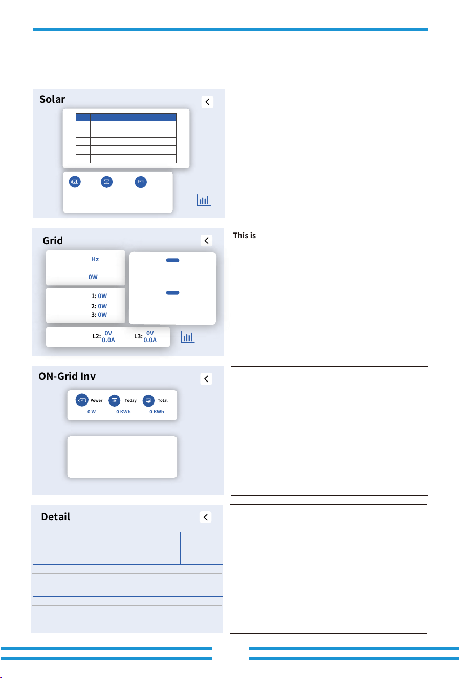
This is Solar Panel detail page.
Click the bar chart icon at the bottom right corner of
the page to view the historical data chart of PV power
generation.
Voltage,Current,Power for each MPPT.
Generation power.
Daily and total PV production.
This is Grid detail page.
This is Inverter detail page.
Click the icons on main screen of LCD display, you can enter the detail pages of "Solar",
"Grid", "On-grid inverter", "Detail", "Generator", "Battery" and "Load".
Solar
PV V I P
1
0 W 0 KWh 0 KWh
0V 0.0A 0W
2 0V 0.0A 0W
3 0V 0.0A 0W
4 0V 0.0A 0W
5 0V 0.0A 0W
Power Today
Total
Detail
Inverter
Battery
Grid
Load
PV
INV_P:
HM: LD:
0W
0.0Hz
AC_T:-100.0 C
0W
0.0V 0.00A
0.0 C
0W
0.0 Hz
0W
0W
0W
0W 0W
0W 0W
0W 0W
L1N:0V 0.0A 0.0W
L1N:0V 0.0A
L2N:0V 0.0A
L3N:0V 0.0A
L2N:0V 0.0A 0.0W
L1N:0V 0.0W
L2N:0V 0.0W
L3N:0V 0.0W
L3N:0V 0.0A 0.0W
Grid
Fre:
0.0 Hz
Power:
0W
0V
0.0A
CT1:
0W
LD1:
0W
L1:
0V
0.0A
L2:
0V
0.0A
L3:
CT2:
0W
LD2:
0W
CT3:
0W
LD3:
0W
BUY
SELL
Today:
0 KWh
Total:
0 KWh
Today:
0 KWh
Total:
0 KWh
①DC/AC inverter module: output power, output frequency, AC_T( The
higher one of the two temperature sensor sampling data). The voltage,
current, and power output of inverter module's each phase.
②PV :Solar generation power
③Battery: Charging/Discharging power
The battery voltage, current, and temperature data sampled by the inverter.
④Load: Total Load consumption power
The voltage and load power of each phase at the inverter's Load port.
⑤Grid: Grid voltage,Grid Frequency.
The voltage and current of each phase at the inverter's Grid port.
HM: The power of each phase at the sampling point calculated using the
sampling data from an external CT/meter.
LD: The power of each phase at the internal sampling point, calculated
using data sampled by the inverter's Grid port built-in sampling circuit.
①
②
③
④
⑤
①Grid Frequency,Grid power
② CT1/2/3:
LD1/2/3:
③The electricity purchased from the grid on the current
day and the total historical purchased electricity;
The electricity sold to the grid on the current day and the
total historical sold electricity.
④The voltage and current of each phase of the grid.
Click the bar chart icon at the bottom right corner of the
page to view the historical data chart of Grid power
consumption.
The upper section displays the on-grid inverter's current
output power, daily energy generation, and total energy
generation. The lower section shows the voltage and
output power of each phase on the output side of the
on-grid inverter.
①
②
③
④
ON-Grid Inv
0 W 0 KWh 0 KWh
Power Today
Total
V_L1: 0 V
V_L2: 0 V
V_L3: 0 V
P_L1: 0 W
P_L2: 0 W
P_L3: 0 W
- 35 -
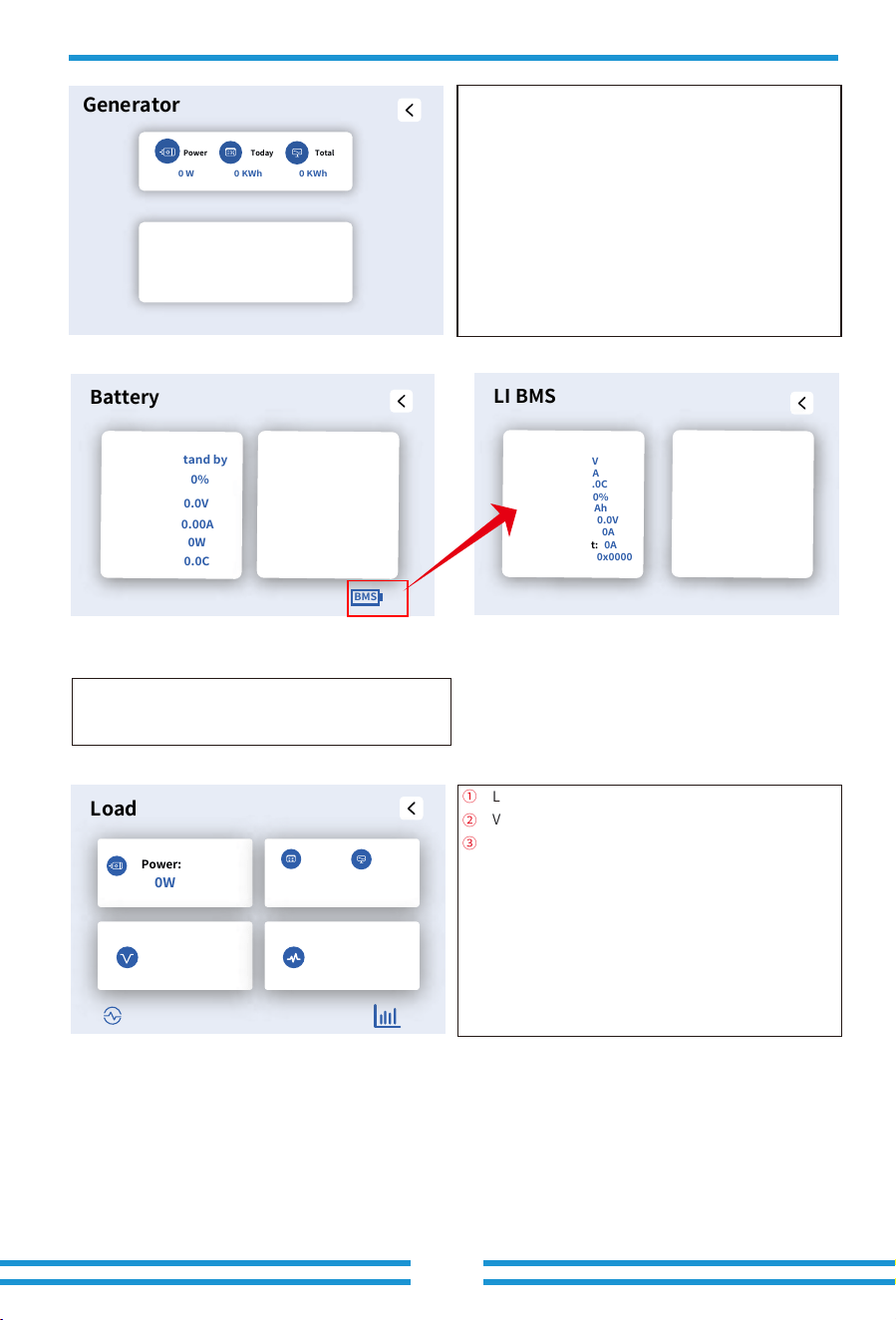
①
②
③
Load Power.
Voltage, Power for each Phase.
Daily and total Load consumption .
This is Battery detail page.
BATTERY DETAIL PAGE
Click the BMS icon on the lower right corner of
Battery detail page, you can enter the BMS page.
Load
0W
Power:
0KWh 0KWh
Today
P2:
0W
P1:
0W
P3:
0W
L1:
0V
L2:
0V
L3:
0V
Total
LI BMS
Li BMS1:
Voltage:
0.0V
Current:
0.0A
Temp:
-100.0C
SOC:
0%
SOH:
0%
Capacity:
0Ah
Charge Voltage:
0.0V
Charge Current:
0A
Discharge Current:
0A
Almars:
0x0000 0x0000
Li BMS2:
Voltage:
0.0V
Current:
0.0A
Temp:
-100.0C
SOC:
0%
SOH:
0%
Capacity:
0Ah
Charge Voltage:
0.0V
Charge Current:
0A
Discharge Current:
0A
Almars:
0x0000 0x0000
DeyeDeye
Battery
Battery1
Status:
Stand by
SOC:
0%
U:
0.0V
BMS
I:
0.00A
Power:
0W
Temp:
0.0C
Battery2
Status:
Stand by
SOC:
0%
U:
0.0V
I:
0.00A
Power:
0W
Temp:
0.0C
When the inverter operates in 'Selling First' or 'Zero Export
to load' modes, the Load power data includes only the
Backup load. When the inverter operates in 'Zero Export to
CT' mode, the Load power data includes both the Backup
Load and Home load.
Long press the wave icon at the bottom left corner of this
page to force the main relays of the GEN port to engage so
that the inverter can supply power to the smart load.
Click the bar chart icon at the bottom right corner of the
page to view the historical data chart of Load power
consumption.
①
②
③
The upper section displays the generator's current output
power, daily energy generation, and total energy
generation. The lower section shows the voltage and
output power of each phase on the output side of the
generator.
Generator
0 W 0 KWh 0 KWh
Power Today
Total
V_L1: 0 V
V_L2: 0 V
V_L3: 0 V
P_L1: 0 W
P_L2: 0 W
P_L3: 0 W
5.3 Curve Page-Solar & Load & Grid
PV1-V: 0V PV1-I: 0.0A PV1-P: 0W
Power: 0W
Solar
Energy
Today=0.0 KWH
Total =0.00 KWH
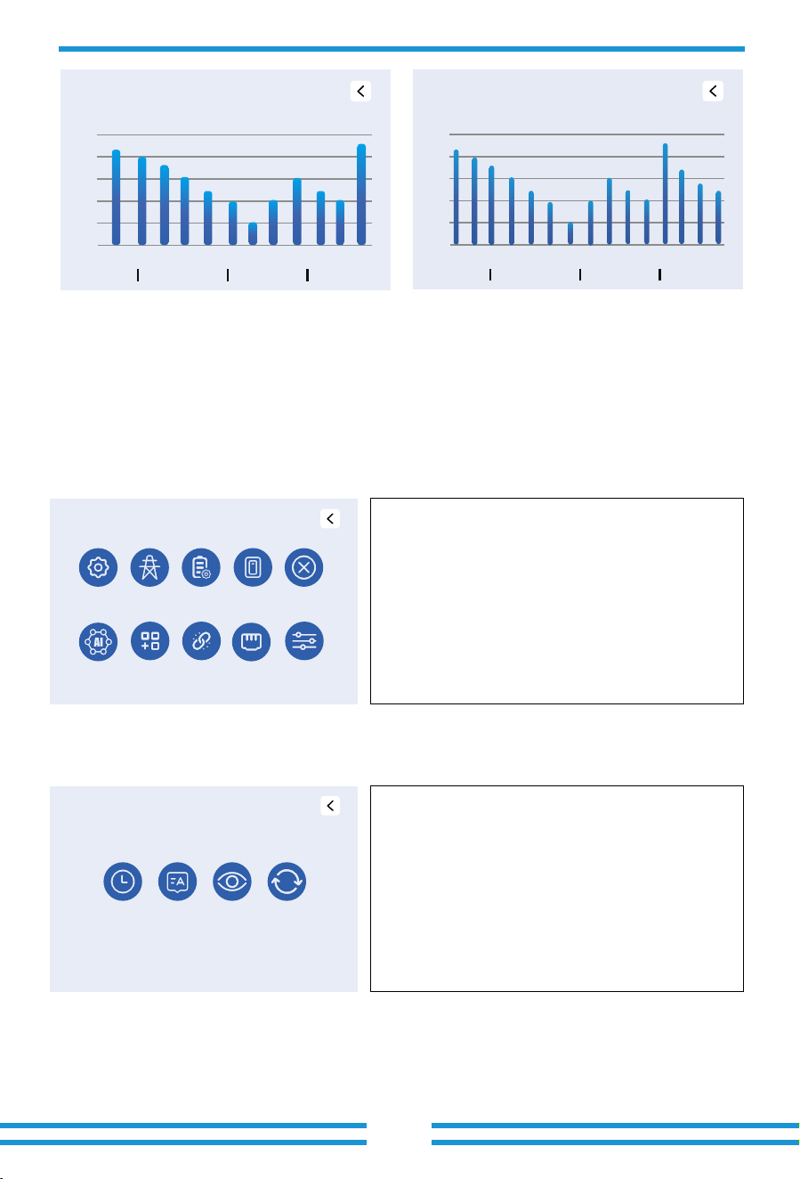
In the home screen of LCD display, click the icons of "Solar", "Grid" and "Load", you can enter
the detail pages of Solar power, Grid power and Load consumption. Click the bar chart icon on
the lower right corner of these detail pages, you can enter the curve page. Using PV as an
example for illustration below.
Solar
PV V I P
1
0 W 0 KWh 0 KWh
0V 0.0A 0W
2 0V 0.0A 0W
3 0V 0.0A 0W
4 0V 0.0A 0W
5 0V 0.0A 0W
Power Today
Total
Day Month Year Total
100%
80%
60%
40%
20%
0%
01 02 03 04 05 06 07 08 09 10 11 12 13 14 15 16 17 18 19 20 21 22 23 24
15 January 26
System Solar Power
Day Month Year Total
100%
80%
60%
40%
20%
0%
January 26
System Solar Power
05
10 15 20 25 30
2000Wh3000W
- 36 -
��% ��%
��.��
04 28 2026 09:25:23
Tue
� ���
� ���
� ���
� ���
ON
�.��
kw
kw
kw
-��.��
kw
�.��
�.��
kw
- 37-
5.4 Setting Menu
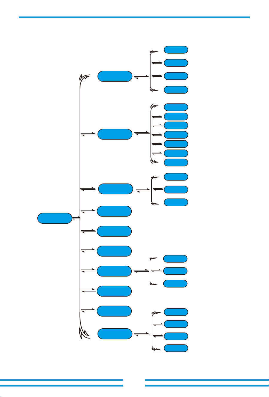
This is the system setting menu page, containing 10
settings items.
Solar power curve for daily, monthly, yearly and total can be roughly checked on the LCD, for more
accuracy power generation, please check on the APP or website of the cloud platform. Click the up
and down buttons below the LCD screen to view the power curves of different time periods. The
operation of checking the grid power and load power is similar to the above operation.
5.5 Basic setup Menu
Click the 'Basic Setup' item on the 'Setting' page to
enter this 'Basic Setup' page, this page contains 4
sub-settings.
Setting
Basic
Setup
Battery
Setup
Net
Grid
Setup
Fault
Code
Aux
Load
Smart
Link
System
Mode
Quick
Control
Advance
-��.��
Basic Setup
Language Display ResetTime
Date
Day Month Year Total
100%
80%
60%
40%
20%
0%
2026200KWh 2MWh
System Solar Power
Jan Feb Mar Apr May Jun Jul Aug Sep Oct Nov Dec
Day Month Year Total
100%
80%
60%
40%
20%
0%
2026 2040
System Solar Power
2026 2027 2028 2029 2030 2031 2032 2033 2034 20402035 2036 2037 2038 2039
2MWh
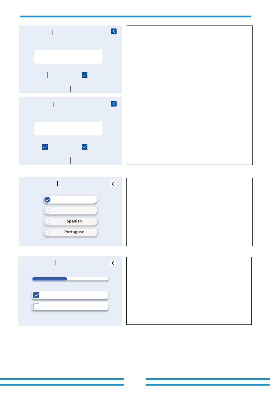
Click the 'Language' sub-setting on the 'Basic Setup'
page to enter this page.
If the display language you want is available on the LCD
screen, please select it directly. If not, please contact the
after-sales support team to confirm whether the desired
display language can be supported via a language
package upgrade.
- 38-
Basic Setup
Display
0% 100%
Brightness
Buzzer
LCD Auto Sleep Mode
Basic Setup Time& Date
Hours
Time Date
Minutes
Use Side To Select A Number
��-Hour
Seconds
�� : ��
��
:
Time Syncs
AM
Basic Setup
Time& Date
Year
Time Date
Month
Use Side To Select A Number
��-Hour
Day
���� ��
��
Time Syncs
Brightness: Adjust the LCD screen brightness by
dragging the progress bar left or right.
LCD Auto Sleep Mode: When enabled, the LCD will
automatically enter sleep mode after 5 minutes of
inactivity.
Buzzer: When enabled, the buzzer will sound during fault
alarm periods.
Click the 'Time&Date' sub-setting on the 'Basic Setup'
page to enter this page.
Time&Date: Slide up and down the corresponding
screen area to adjust the time to match the local
time,and then go to the date page and adjust the date
using the same method.
24-Hour: Use 24-hour format.
Time Syncs: Automatic Time Sync with Cloud Server.
Basic Setup
Language
Select your default Language
English
French
Spanish
Portuguse
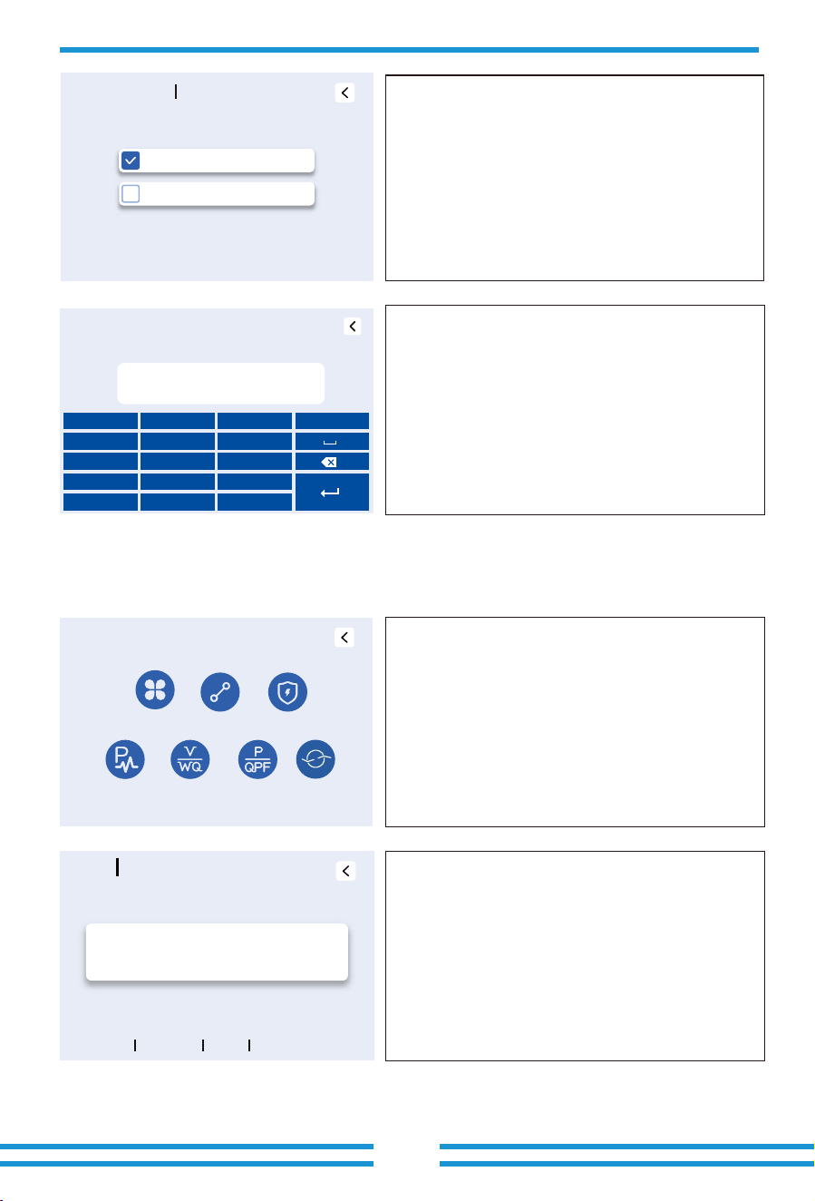
Factory Reset Password: 9999
Lock all changes Password: 7777
When we select the "factory reset" or"Lock all changes", the
system will require you to enter a password first to confirm
the operation.
Click the 'Grid Setup' item on the 'Setting' page to enter this
'Grid Setup' page, this page contains 7 sub-settings.
Click the 'Type' sub-setting on the 'Grid Setup' page to enter
this page.
①:Press UP or DOWN button to select the desired 'Grid
Code' .
- 39-
5.6 Grid Setup Menu
Basic Setup
Reset
Lock All Changes
Factory Reset
Pass Key Required
� � �
+
-
*
/
� � �
� � �
, � .
Grid Setup
Type
Connect
IP
F(W) V(W)
V(Q)
P(Q)
P(PF)
H/LVRT
Grid
Type
Mode
Frequency Type
INV Output Voltage
Press UP or DOWN button to switch option.
General Standard
0/37
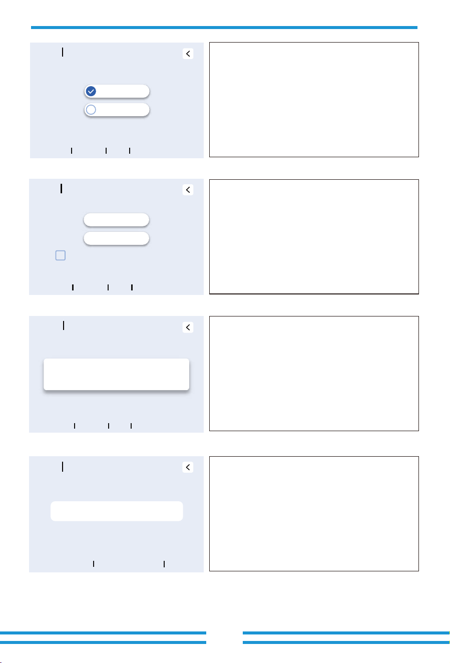
Factory Reset: Restore all parameters to factory defaults
and delete all historical data.
Lock All Changes: After enabling, all parameters will be
locked and cannot be modified.
①
- 40-
In scenarios with a power grid or generator, set this
parameter according to the grid or generator frequency; In
off-grid scenarios without a grid or generator, set this
parameter according to the load's rated frequency.
0/120/240: Select this setting when the three live wires of
the power grid are connected in L1/L2/L3
(L2/L3/L1,L3/L1/L2)sequence.
0/240/120: After grid connection, if the inverter alarms W03,
change the grid phase sequence from '0/120/240' to this
option.
IT_system-neutral is not grounded: When the system's
power grid is a three-phase three-wire IT-type grid, please
enable this option.
In scenarios with a power grid or generator, set this
parameter according to the grid or generator voltage. In
off-grid scenarios without a grid or generator, set this
parameter according to the backup load's rated voltage.
Click the 'Connect' sub-setting on the 'Grid Setup' page to
enter this page.
Normal Ramp rate(s): The time required for the inverter's
output power to increase from zero to its rated output power
during normal startup.
Grid
Type
50 Hz
60 Hz
Mode
Frequency Type
INV Output Voltage
Grid
Type
0/120/240
0/240/120
IT_system-neutral is not grounded
Mode
Frequency Type
INV Output Voltage
Grid
Type
LN:220VAC LL:380VAC
INV Output Voltage
Mode
Frequency Type
INV Output Voltage
Grid
Connect
Normal Connect Reconnect After Trip Other
Normal Ramp rate
00 S
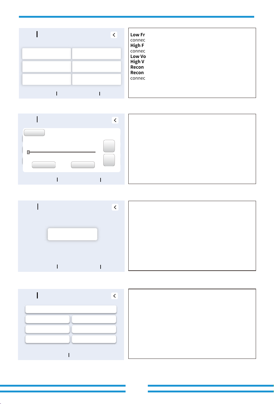
Low Frequency: Grid frequency lower limit for grid
connection
High Frequency: Grid frequency upper limit for grid
connection
Low Voltage: Grid voltage lower limit for grid connection
High Voltage:Grid voltage upper limit for grid connection
Reconnect Ramp Rate: It is the reconnection power ramp.
Reconnect Time:The waiting time for the inverter
connects the grid again after tripping.
Methods to set the parameter values for the above Low/High
Frequency and Low/High Voltage:
(1) Click the 'Keyboard' button in the top-left corner to use
the pop-up keyboard for entering the desired value.
(2) Drag the progress bar left or right on the screen to the
desired value position.
(3) Click or long-press the ‘+’ or ‘-’ button on the right
side of the LCD or the UP/DOWN physical button to adjust
the value.
After adjusting the value, click the 'OK' button on the LCD or
the physical 'Enter' key to confirm and save, or click the
'Cancel' button on the LCD or the physical 'Esc' key to cancel
the changes and return.
Cosphi: Power factor. When the power factor is set to a
positive value, the inverter absorbs reactive power from the
grid; when power factor is set to a negative value, the
inverter can deliver reactive power to the grid.
Click the 'IP' sub-setting on the 'Grid Setup' page to enter
this page.
OverVoltage U(10min,running mean): The average value
of the grid voltage over 10 minutes must not exceed this set
value. If exceeded, the inverter will disconnect from the grid
for protection.
HV1: Level 1 Overvoltage Point and Trip Time
HV2: Level 2 Overvoltage Point and Trip Time
HV3: Level 3 Overvoltage Point
LV1: Level 1 Undervoltage Point and Trip Time
LV2: Level 2 Undervoltage Point and Trip Time
LV3: Level 3 Undervoltage Point
- 41-
Grid
Connect
Normal Connect Reconnect After Trip Other
0.00 Hz
Low Frequency
0.00 Hz
High Frequency
0.0 V
Low Voltage
0.0 V
High Voltage
00 S
Reconnection Time
00 S
Reconnect Ramp rate
Keyboard
Low Frequency
45.00 Hz
Min-
0.00 Hz
Value
0.00 Hz
Max+
OK Cancel
+
-
Grid
Connect
Normal Connect Reconnect After Trip Other
Cosphi
0.000
Grid
Connect
Normal Connect Reconnect After Trip Other
0.00 Hz
Low Frequency
0.00 Hz
High Frequency
0.0 V
Low Voltage
0.0 V
High Voltage
0 S
Reconnection Time
00 S
Reconnect Ramp Rate
Grid
Ip
Voltage Frequency
0.0 V
Over Voltage U (10min,running mean)
HV1 0.0 V LV1 0.0 V
LV2
0.0 V
LV3 0.0 V
HV2 0.0 V
HV3 0.0 V
0.00 S
0.00 S
0.00 S
0.00 S
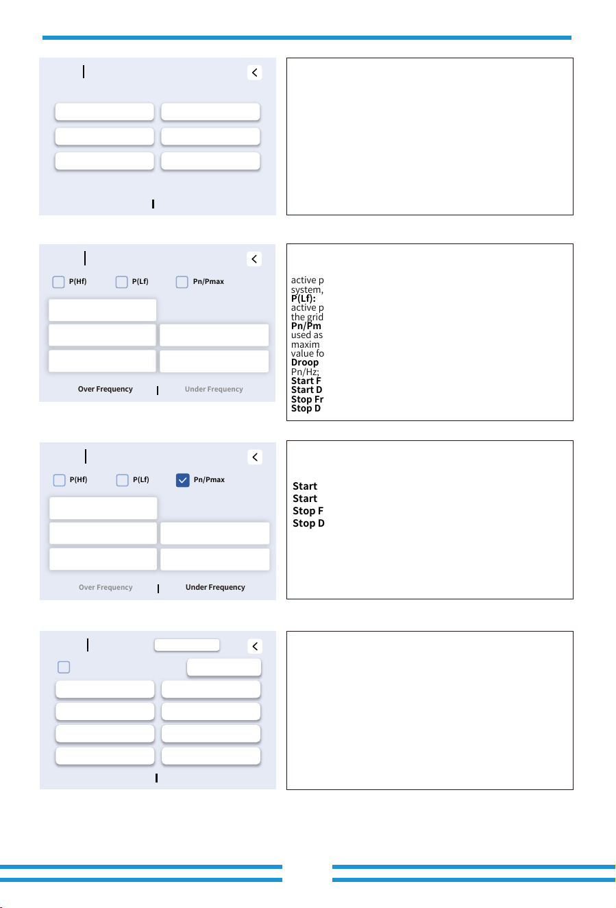
HF1: Level 1 Overfrequency Point and Trip Time
HF2: Level 2 Overfrequency Point and Trip Time
HF3: Level 3 Overfrequency Point
LF1: Level 1 Underfrequency Point and Trip Time
LF2: Level 2 Underfrequency Point and Trip Time
LF3: Level 3 Underfrequency Point
- 42-
Grid
Ip
Voltage Frequency
HF1
0.00 Hz
LF1 0.00 Hz
LF2
0.00 Hz
LF3 0.00 Hz
HF2
0.00 Hz
HF3
0.00 Hz
0.00 S
0.00 S
0.00 S
0.00 S
Click the 'F(W)' sub-setting on the 'Grid Setup' page to enter this
page.
P(Hf): When the grid frequency is high, the inverter reduces its
active power output to decrease the excess energy in the grid
system, helping to restore grid frequency stability.
P(Lf): When the grid frequency is low, the inverter will increase its
active power output to help compensate for the power deficit of
the grid system, thereby stabilizing the grid frequency.
Pn/Pmax: When enabled, the rated output power of the inverter is
used as the reference value for Droop F. When disabled, the
maximum output power of the inverter is used as the reference
value for Droop F.
Droop F: P(HF) Droop Rate.When pn/Pmax is enabled, the unit is
Pn/Hz; When Pn/Pmax is disabled, the unit is Pmax/Hz.
Start Frequency F: P(HF) Start Frequency.
Start Delay: P(HF) mechanism start-up delay time.
Stop Frequency F: P(HF) Stop Frequency.
Stop Delay: P(HF) mechanism stop delay time.
Droop F: P(Lf) Droop Rate. When Pn/Pmax is enabled, the
unit is Pn/Hz; When Pn/Pmax is disabled, the unit is
Pmax/Hz.
Start Frequency F: P(Lf) Start Frequency.
Start Delay: P(Lf) mechianism start-up delay time.
Stop Frequency F: P(Lf) Stop Frequency.
Stop Delay: P(Lf) mechianism stop delay time.
Click the 'V(W) V(Q)' sub-setting on the 'Grid Setup' page to
enter this page.
Mincosphi: Keep the default values under the current Grid
code, no modification is needed.
P(U): Voltage-dependent Active Power Control. Adjust active
power output automatically based on the grid connection point
voltage, the higher the voltage, the lower the output.
R.T(3Tau): Dynamic response time of P(U) voltage control.
V1: Grid voltage level 1
P1: Upper limit of active power output level 1
V2: Grid voltage level 2
P2: Upper limit of active power output level 2
V3: Grid voltage level 3
P3: Upper limit of active power output level 3
V4: Grid voltage level 4
P4: Upper limit of active power output level 4
Grid
F(W)
Over Frequency Under Frequency
P(Hf)
P(Lf) Pn/Pmax
Start Delay F
Droop F
0%Pmax/Hz
Stop Delay F
Start Frequency F
0.00 Hz
0.00 Hz 0.00 s
0.00 s
Stop Frequency F
Grid
F(W)
Over Frequency Under Frequency
P(Hf) P(Lf) Pn/Pmax
Start Delay F
Droop F
0%Pn/Hz
Stop Delay F
Start Frequency F
0.00 Hz
0.00 Hz 0.00 s
0.00 s
Stop Frequency F
Grid
V(
W) V
(Q)
V(W) V(Q)
P(U)
V1
109.0 %Un
P1
100 %
R.T(3Tau)
Mincosphi 1.000
10.0s
V2
111.0 %Un
P2
80 %
V3 113.0 %Un P3 60 %
V4 115.0 %Un
P4
0 %
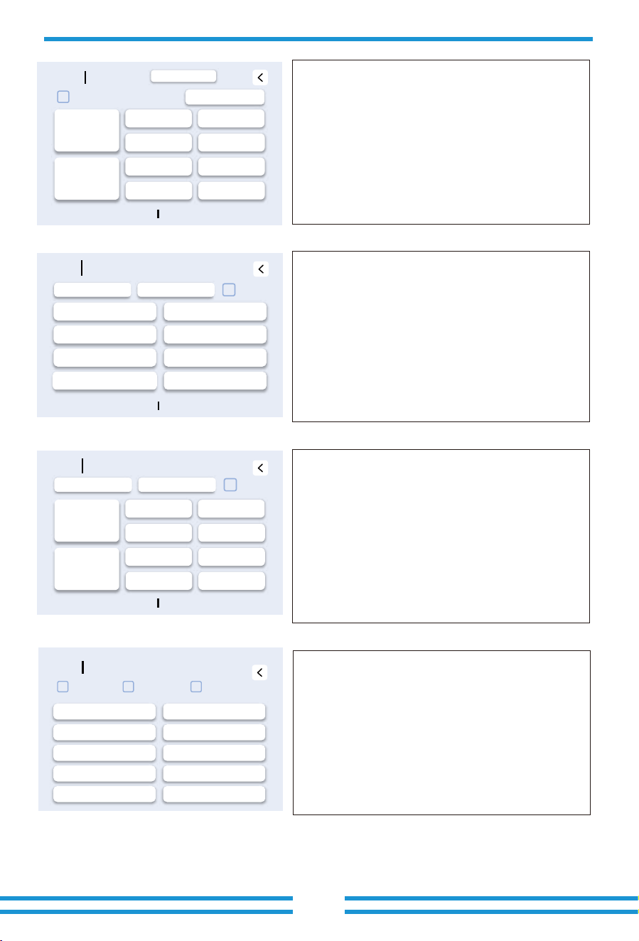
Grid
V(W) V(Q)
V1
0.0 %Un
Q1
0 %
Q2
0 %
Q3
0 %
Q4
0 %
V2
0.0 %Un
V3
0.0 %Un
V4
0.0 %Un
0 %
Lock-in/Pn
0 %
Lock-out/Pn
Q(U)
Mincosphi 0.000
R.T(3Tau)
0.0s
V(
W) V
(Q)
- 43-
Grid
P(Q) P(PF)
P(Q) P(PF)
P1
0 %
PF1
0.000
PF2
0.000
PF3
0.000
PF4
0.000
P2
0%
P3
0 %
P4
0%
0.0 %
Lock-in/Pn
0.0 %
Lock-out/Pn
Fixed Q
0.0%
R.T(3T au)
0.0s
P(PF)
Grid
P(Q) P (PF)
P(Q) P(PF)
P1
Q1
0%
P2 Q2
0%
0%
0%
P3 Q3 0%
P4
Q4
0%
Fixed Q
0.0%
R.T(3T au)
0.0s
P(Q)
0%
0%
Grid
LVRT
HV2
HV2_T
HV3
0 %
0 %
HV3_T
0.00s
0.00s
HV1 HV1_T
0.00s
LV1 LV1_T 0.00s
LV2
LV2_T
0.00s
0 %
0 %
0 %
LVRT HVRT Zero丨enable
Click the 'H/LVRT' sub-setting on the 'Grid Setup' page to enter
this page.
LVRT/HVRT: When the voltage of the power grid reaches the set HV
or LV, the relay at the inverter grid port will remain closed for the
set time to maintain stable grid connection without tripping.
Click the 'P(Q) P(PF)' sub-setting on the 'Grid Setup' page to
enter this page.
P(Q): The inverter automatically outputs or absorbs reactive
power according to the preset ratio based on the current active
power output.
Fixed Q: The inverter will output or absorb reactive power at a
fixed percentage as set.
R.T(3Tau): Dynamic Response Time of P(Q) Active-Reactive
Power Control.
P1: Active power output point 1
Q1: Reactive power output point 1
P2: Active power output point 2
Q2: Reactive power output point 2
P3:Active power output point 3
Q3: Reactive power output point 3
P4:Active power output point 4
Q4: Reactive power output point 4
P(PF): Dynamically adjust the inverter's power factor by
controlling the output ratio of active and reactive power, based
on the demand for active power.
P1/P2/P3/P4: Active power output point 1/2/3/4
PF1/PF2/PF3/PF4: PF1 means that when the inverter's active
power output reaches the set value P1, its power factor will be
maintained at this configured value; points 2, 3, and 4 follow
accordingly.
Lock-in/Pn: When the ratio of the inverter's active power
output to its rated power is below this set value, the P(PF)
control mechanism will become inactive.
Lock-out/Pn: When the ratio of the inverter's active power
output to its rated power reaches this set value, the P(PF)
control mechanism will be activated.
Q(U): The inverter can automatically adjust its reactive power output based
on real-time grid voltage variations to stabilize the voltage at the point of
common coupling (PCC). It absorbs inductive reactive power when the grid
voltage is too high, and delivers inductive reactive power when the grid
voltage is too low.
R.T(3Tau): Dynamic response time of Q(U) voltage control.
Lock-in/Pn: When the active power output by the inverter is below this set
threshold, the Q(U) control mechanism will not be effective.
Lock-out/Pn: When the active power output by the inverter reaches this set
threshold, the Q(U) control mechanism begins to take effect.
V1: Grid Voltage point 1
V2: Grid Voltage point 2
V3: Grid Voltage point 3
V4: Grid Voltage point 4
Q1: Reactive power output point 1
Q2: Reactive power output point 2
Q3: Reactive power output point 3
Q4: Reactive power output point 4
Zero|enable: When the grid voltage drops abruptly to near 0V
due to faults such as short circuits or lightning strikes, the
inverter will remain grid-connected and continue operating
without disconnecting or tripping within a specified time, and
quickly resume normal power output after voltage recovery.
HV 3/2/1: Grid overvoltage level 3/2/1
HV 3/2/1_T: The Level 3/2/1 hold time corresponding to the
level 3/2/1 Grid overvoltage threshold
LV 1/2: Grid undervoltage level 1/2
LV 1/2_T: The Level 1/2 hold time corresponding to the level 1/2
Grid undervoltage threshold
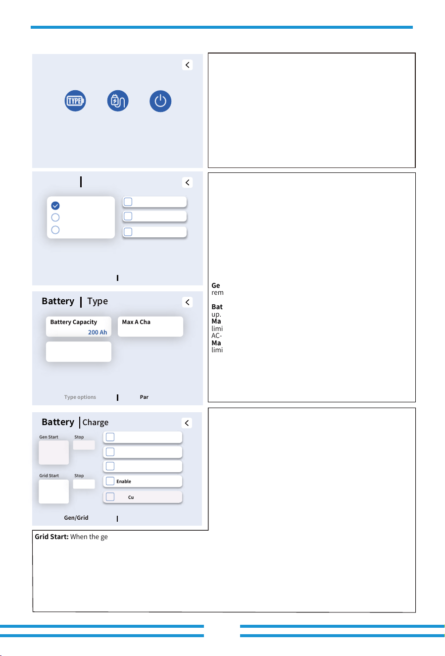
5.7 Battery Setup Menu
- 44 -
Battery Setup
Battery
Type
Battery
Charge
Shut
Down
Battery
Type
Parameters
Type options
No Battery
Lithium
Use Batt V
Off INV off battery
Parallel bat1&bat2
Gen Force
Click the 'Battery Charge' sub-setting on the 'Battery Setup' page
to enter this page.
Click the 'Battery Type' sub-setting on the 'Battery Setup' page
to enter this page.
No Battery: Check this option if no battery is connected to the
system.
Lithium: When using batteries from the 'Approved Battery List'
that can communicate with the inverter, check this option.
Use BattV: When using a lithium-ion battery that cannot
communicate with the inverter, check this option.
Off INV off battery: When the inverter receives a remote
shutdown command, the battery connected to this inverter will
also be turned off.
Parallel bat1&bat2: When using the inverter's two battery
power terminals and the BMS1 communication port to connect
only one battery set (which can be multiple clusters connected
in parallel), this function must be enabled.
Gen Force: Manually activate the 'G-Start' dry contact once to
remotely start the connected generator.
Battery Capacity: Reserved, currently unused, no need to set
up.
Max A Charge: The upper limit of battery charging current
limited by this hybrid inverter, including DC-DC charging and
AC-DC charging
Max A Discharge: The upper limit of battery discharging current
limited by this hybrid inverter.
Click the 'Battery Setup' item on the 'Setting' page to enter this
'Battery Setup' page, this page contains 3 sub-settings.
Gen Start:The SOC threshold for triggering the closure of the
G-start dry contact. When the battery SOC drops below this set
value and the Gen signal is enabled, the G-start dry contact will
close to remotely start the generator.
A(@Gen Start): The maximum battery charging current limit by
the inverter when only using AC power input from the GEN port to
charge the battery.
Stop(@Gen Start): Only effective when the User Timer function is
disabled, this setting controls the disconnection of the G-Start dry
contact. When the battery SOC rises above this set value, the
G-Start dry contact is triggered to open, remotely shutting down
the generator. The generator icon on the inverter's LCD will
disappear, and if the generator is connected to the hybrid
inverter's GEN port, the main relays at the GEN port will also
disconnect simultaneously. This set value is constrained to be no
less than the "Gen Start" set value + 5%.
Grid Start: When the generator is connected to the inverter's Grid port and is already running, this setting controls the
closing of the main relays at the inverter's Grid port once the battery SOC drops below this set value. The Grid Start set value
must be less than the Gen Start set value. The Grid Start set value must be less than the Gen Start set value.
A(@Grid Start): The maximum battery charging current limit by the inverter when only using AC power input from the Grid
port to charge the battery.
Stop(@Grid Start): This setting is effective only when the generator is connected to the inverter's Grid port and the User
Timer function is disabled. When the battery SOC rises to this set value, it triggers the disconnection of the main relays at the
inverter's grid port. This set value is constrained to be no less than the "Grid Start" set value + 5%, and less than the
Stop(@Gen Start) set value.
Gen Charge: Whether to allow AC power input from the GEN port to charge the battery. When the User Timer is enabled, this
can be controlled separately for different time periods.
Battery
Charge
Gen Charge
Gen Signal
Grid Charge
Cut off Grid @SOC>Stop
Gen/Grid
Parameters
Enable Grid Start &Stop Value
30%
20 A
25%
95%
90%
20 A
Battery
Type
Parameters
Type options
Battery Capacity
200 Ah
Max A Charge
20 A
Max A Discharge
20 A
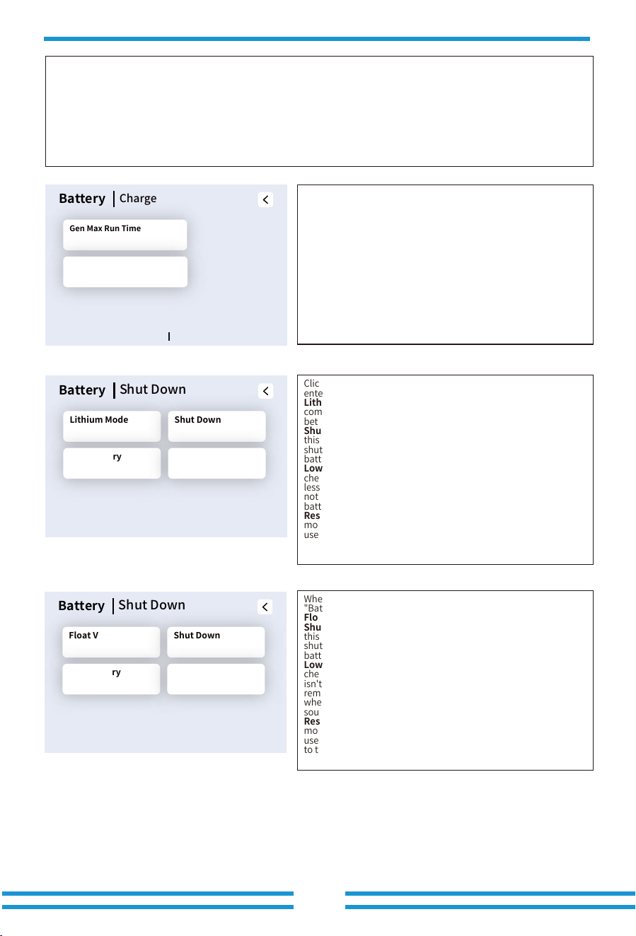
- 45 -
Click the 'Shut Down' sub-setting on the 'Battery Setup' page to
enter this page.
Lithium Mode: Please refer to the officially released battery
compatibility list to find the communication protocol number
between the current battery model and the inverter.
Shutdown : Be valid in Off-grid mode, battery can discharge to
this voltage, then the DC/AC inverter module of this inverter will be
shut down and the solar power can only be used to charge the
battery.
Low Batt: In on-grid mode, when the 'Grid charge' has been
checked and the set target battery SOC on 'Use Timer' page isn't
less than the set value of "Low Batt" , the battery SOC will remain
not less than the set value of "Low Batt". In off-grid mode, when
battery SOC drops to this set value, the beeper will sound.
Restart :Be valid in Off-grid mode, after the DC/AC inverter
module of this inverter is shut down, the PV power can only be
used to charge the battery. After the battery SOC has resumed to
this "Restart" value, the DC/AC inverter module will restart to
output AC power.
When the "Use Batt V" mode is selected, the content on the
"Battery|Shut Down" page is shown in the figure on the
left
.
Float V: Floating charge voltage of the battery.
Shutdown : Be valid in Off-grid mode, battery can discharge to
this voltage, then the DC/AC inverter module of this inverter will be
shut down and the solar power can only be used to charge the
battery.
Low Batt: In on-grid mode, when the 'Grid charge' has been
checked and the set target battery voltage on 'Use Timer' page
isn't less than the set value of "Low Batt" , the battery voltage will
remain not less than the set value of "Low Batt". In off-grid mode,
when battery Voltage drops to this set value, the beeper will
sound.
Restart :Be valid in Off-grid mode, after the DC/AC inverter
module of this inverter is shut down, the PV power can only be
used to charge the battery. After the battery voltage has resumed
to this "Restart" value, the DC/AC inverter module will restart to
output AC power.
Gen Signal: Whether to use the G-Start dry contact to remotely control the start and stop of the generator.
Grid Charge: Whether to allow AC power input from the Grid port to charge the battery. When the User Timer is enabled,
this can be controlled separately for different time periods.
Enable Grid Start&Stop Value: Whether to use Grid Start and Stop (@Grid Start) to control the status of the Grid port's
main relays, when the generator is connected to the inverter's Grid port and the User Timer function is disabled.
Cut off Grid@SOC>Stop: When the generator is connected to the inverter's Grid port, the User Timer function is disabled,
and the Enable Grid Start & Stop Value function is enabled, enabling this feature will cause the main relay at the inverter's
Grid port to disconnect when the battery SOC rises above this set value.
Battery
Shut Down
Lithium Mode Shut Down
Low Battery Restart
00 10%
20% 50%
Battery
Charge
Gen Max Run Time
Gen Down Time
24.0 h
0.0 h
Gen/Grid
Parameters
Battery
Shut Down
Float V Shut Down
Low Battery Restart
552.0 V 160.0 V
170.0 V 180.0 V
Gen Max Run Time: It indicates the longest time Generator can run
in one day, when time is up, the Generator will be turned off. 24H
means that it does not shut down all the time.
Gen Down Time: It indicates the rest time of the generator before
the inverter start it again.
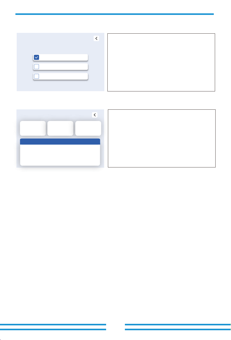
Quick Control
Beeper Override
LCD Auto Sleep Mode(5 mins)
Force Generator
Info& Fault Code
ID:
COMM:0001-200C-C001
MCU:0000-0000-0000
ARC:0000
Grid Standard:0
BMS1:
BMS2:
Fault Code Occueerd
5.8 Quick Control Menu
5.9 Info and Fault Code Menu
Click the 'Quick Control' item on the 'Setting' page to enter this
page, this page contains 3 parameters.
Force generator: Manually activate the 'G-Start' dry contact
once to remotely start the connected generator.
Beeper Override: Silence the beeper.
LCD Auto Sleep Mode(5 mins): When enabled, the LCD will
automatically enter sleep mode after 5 minutes of inactivity.
Click the 'Fault Code' item on the 'Setting' page to enter this
page, this page contains 4 zones.
Zone 1 displays the inverter's serial number, the firmware
version of the COMM board, and the firmware version of the
MCU board.
Zone 2 displays the firmware version of the ARC board and the
configured Grid code.
Zone 3 displays the firmware versions of the two battery sets (if
installed).
Zone 4 displays the information of fault.
- 46 -
① ② ③
④
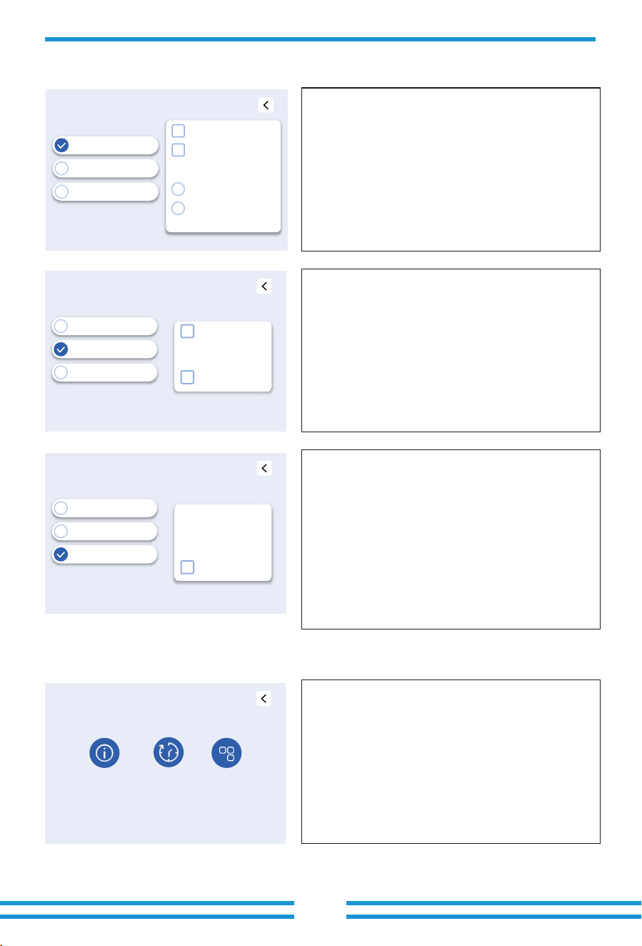
- 47 -
Gen & Aux Load
ON-Grid Inv
Smart Load Output
Generator Input
OFF Batt
ON Batt
On Grid always on
450.0 V
550.0 V
GEN connect to Grid input
Gen & Aux Load
ON-Grid Inv
Smart Load Output
Generator Input
OFF Batt
ON Batt
AC Couple Frz High
MI export to Grid cutoff
550.0 V
450.0 V
0.00Hz
Gen & Aux Load
Gen Peak Shaving
GEN Connect to Grid input
Rated Power
0 W
AC Couple On Grid Side
AC Couple on Load Side
ON-Grid Inv
Smart Load Output
Generator Input
System Mode
System
TOU
System
Limited
System
Mode
+
5.10 Gen and Aux Load Menu
5.11 System Mode Menu
Click the 'Aux load' item on the 'Setting' page to enter this 'Gen & Aux Load'
page, this page contains 3 sub-settings.
The GEN port is a multifunctional port, but only one of the following three
functions can be selected when using this port.
Generator Input: Used as an AC input to connect external AC generator
source.
Gen Peak Shaving Power: Limit the maximum output power of the
generator to the set 'Rated power' below, the rest of power consumption will
be provided by inverter to ensure that the generator will not overload.
GEN Connect to Grid input: Connect the AC generator source to the grid
input port of this inverter.
Rated Power: The expected maximum output power of the AC generator,
which usually does not exceed 80% of the generator's actual rated capacity.
AC Couple On Grid Side: Connect other AC power sources (such as on-grid
inverters) at the Grid port side of this hybrid inverter.
AC Couple On Load Side: Connect other AC power sources (such as on-grid
inverters) at the Load port side of this hybrid inverter.
Smart Load Ouput: Use the GEN port as an AC output port. The inverter can
control the power supply to the load connected to this port by controlling
the state of the main relays of the GEN port.
OFF Batt: When the battery's SOC/voltage drops to this set value, the
inverter will disconnect the main relays of the GEN port and stop supplying
power to the smart load.
ON Batt: When the battery's SOC/voltage rises to this set value, the inverter
will engage the main relays of the GEN port and start supplying power to the
smart load.
On grid always on: When enabled, if the hybrid inverter operates in
grid-connected mode, its main relays of the GEN port will remain engaged,
allowing the inverter to continuously supply power to the smart load.
Click the 'System Mode' item on the 'Setting' page to enter this 'System
Mode' page, this page contains 3 sub-settings.
On-grid INV Input: Use the GEN port as an AC input port, through which the
output power from other grid-following AC sources (such as on-grid
inverters) can be fed into the hybrid inverter.
OFF Batt: When the hybrid inverter operates in off-grid mode, once the
SOC/voltage of the connected battery rises to this set value, the hybrid
inverter will disconnect the main relay of its GEN port, there by cutting off the
power supply from the external AC source (such as on-grid inverters) to
prevent the battery from being overcharged.
ON Batt: When the hybrid inverter operates in off-grid mode, once the
SOC/voltage of the connected battery drops to this set value, the hybrid
inverter will engage the main relays of its GEN port, thereby feeding the
power from the external AC source (such as on-grid inverters) into the hybrid
inverter to charge the battery.
AC Couple Frz High: When the hybrid inverter operates in off-grid mode and
an on-grid inverter is AC-coupled to its GEN or Load port, once the battery
SOC/voltage rises to the 'OFF Batt' set value, the hybrid inverter will increase
its AC output frequency to a predefined trip threshold (e.g., 52 Hz), causing
the grid-following inverter to disconnect automatically.
MI export to Grid cutoff: Disconnect the main relays of the GEN port to
prevent the excess part of the AC power output by the on-grid inverter from
being fed into the grid.
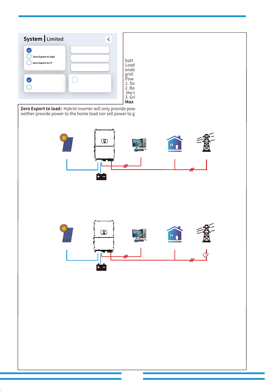
Selling First: This Mode allows hybrid inverter to sell
back any excess power produced by the solar panels to
the grid. If "Use Timer" is enabled, the battery energy also
can be sold into grid.
Photovoltaic power is prioritized for load consumption or
battery charging (the specific priority depends on whether
Load First or Batt First is set, and whether grid charging is
enabled), and only the surplus power can be exported to the
grid.
Power source priority for the load is as follows:
1. Solar power(including AC coupled on-grid inverters )
2. Batteries(when the actual battery SOC is higher than
the target SOC).
3. Grid or generator.
Max Solar Power: the maximum DC input power allowed.
Grid
Backup Load
On-Grid Home Load
Battery
Solar
Grid
Backup Load
On-Grid Home Load
Battery
Solar
CT
Zero Export to load: Hybrid inverter will only provide power to the backup load connected. The hybrid inverter will
neither provide power to the home load nor sell power to grid,if the "solar sell" behind is not enabled. The built-in
CT will detect power flowing back to the grid and will reduce the power of the inverter only to supply the backup
load and charge the battery. Load consumption=Backup load.
Zero Export to CT : Hybrid inverter will not only provide power to the backup load connected but also give power
to the home load connected. If PV power and battery power is insufficient, it will take grid energy as supplement.
The hybrid inverter will not sell power to grid,if the "solar sell" behind is not enabled. In this mode, external CTs or
smart meter must be installed. For the installation method of CTS or smart meter, please refer to the section 3.7 .
The external CTs or smart meter will detect power flowing back to the grid and will reduce the power of the inverter
only to supply the backup load, home load and charge the battery. Load consumption=Backup load+home load.
Max. sell power: Maximum power allowed to flow to grid.
Zero-export Power: This parameter will ensure the zero-export by taking from the grid some small amount of
power that has been set with this value. It is recommended to set it as 20-100W to ensure the hybrid inverter won'
t feed power to grid.
Batt First: PV power is firstly used to charge the battery, and the excess power will be used to power the load. If
the PV power cannot meet the battery charging power demand, the grid can supplement power to charge the
battery while bearing the load power.
Load First: PV power is firstly used to power the load, and the excess power will be used to charge the battery. If
the photovoltaic power cannot solely meet the load's power demand, the shortfall will be supplemented by the
battery and the grid.
Grid Peak Shaving: when it is enabled, grid power will be limited within the set value. If the grid peak shaving
power +PV power+battery power cannot meet the power consumption of the load after peak shaving, the grid
peak shaving will be invalid, and the power taken from the grid can exceed this set value.
- 48 -
System
Limited
Selling First
Zero Export to load
Zero Export to CT
Batt First
Load First
Zero Export Power
0W
Max Solar Power
0W
Max Sell Power
0W
0W
Grid Peak Shaving
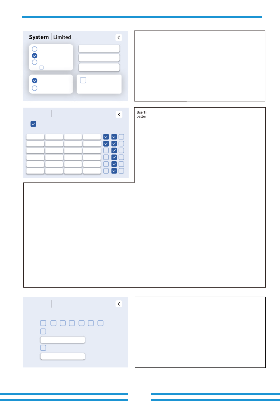
- 49 -
System
Mode
Mon
Soft export conrtol set
Tue Wed SatThu Fri Sun
P
0.0%Pmax
P
0.0%Pmax
Hard export control set
Mon/Tue/Wed/Thu/Fri/Sat/Sun: It allows users to choose
which day to execute the setting of "Use Timer".
Use Timer: it is used to program when to use grid or generator to charge the
battery, and when to discharge the battery to power the load. Only when 'Use
Timer' is checked can the parameters below be set.
Note: Only when the hybrid inverter operates in selling first mode and the 'Use
Timer' has been enabled, the battery power can be sold to the grid.
Time: The start time of the current period and the end time of the previous period.
Note: 1. For more flexible and controllable use of batteries, it is recommended to
enable the "Use Timer" function.When the inverter is operating in on-grid mode
and "Use Timer" is not enabled, the inverter can charge normally, but only
discharge to provide the inverter's self-consumption power, without discharging to
power the loads.
2. Only the 6th time period is allowed to cross midnight.
Power: The maximum allowed discharge power of the battery is only valid in the
"Selling First" mode.
Batt: The target value of battery voltage or SOC during the current time period. If
the actual SOC or voltage of the battery is lower than the target value, the battery
needs to be charged. If there is a energy source like solar power or grid, the battery
will be charged; If the actual SOC or voltage of the battery is higher than the target
value, the battery can discharge, and when the solar power is not enough to power
the load or the "Selling First "is enabled, the battery will discharge.
Soft export control set:The export power is limited by software,
such that the upper limit of export power as a percentage of the
maximum AC output active power does not exceed this set value.
Hard export control set:The export power is limited by hardware,
such that the upper limit of export power as a percentage of the
maximum AC output active power does not exceed this set value.
Solar sell: It's the sub-setting of 'Zero export to load' and 'Zero export to CT'
mode. When it is active, the energy generated by the PV array will first power
the loads and charge the battery, and then the excess PV power can be sold to
the grid.
System
Limited
Batt First
Load First
Zero Export Power
0W
Max Solar Power
0W
Max Sell Power
0W
0W
Grid Peak Shaving
Solar Sell
Selling First
Zero Export to load
Zero Export to CT
Assuming that at the end of the previous time period, the actual battery SOC/voltage reaches or approaches the target value of the previous time period.
For example
During 00:00-05:00,
if battery SOC is lower than 80%, it will use grid to charge the battery until battery SOC reaches 80%.
During 05:00-08:00,
if battery SOC is higher than 40%, hybrid inverter will discharge the battery until the SOC reaches 40%. At the same time, if battery SOC is lower than 40%,
then grid will charge the battery SOC to 40%.
During 08:00-10:00,
if battery SOC is higher than 40%, hybrid inverter will discharge the battery until the SOC reaches 40%.
During 10:00-15:00,
If battery SOC is lower than 80%, hybrid inverter will charge the battery until the SOC reaches 80%. If the PV power is sufficient, the battery can be charged
to 100%.
During 15:00-18:00,
when battery SOC is higher than 40%, hybrid inverter will dischargethe battery until the SOC reaches 40%.
During 18:00-00:00,
when battery SOC is higher than 35%, hybrid inverter will dischargethe battery until the SOC reaches 35%.
GEN(%): When the "Use Timer" function is enabled, the G-S dry contact will open when the battery SOC rises to (GEN% - 1%). Consequently, the
generator icon on the inverter's LCD will disappear, and the inverter will disconnect the main relays between itself and the generator. The set value for
"Batt" (the target value for battery SOC/voltage) should be less than (GEN% - 1%).
Grid: It allows AC power to be drawn from the Grid port side for battery charging.
Gen:
It allows AC power to be drawn from the Gen port side for battery charging.
Sell: When enabled, during the current time period, the work mode will be "Selling first", which the excess photovoltaic power and battery discharging
power can be sold to the grid.
System
TOU
Use Timer
Power Batt Gen Grid GenTime
Sell
00:05
05:00
08:00
10:00
15:00
18:00
125000W 80%
40%
40%
80%
40%
35%
0%
125000W 0%
125000W 0%
125000W 0%
125000W 0%
125000W 0%
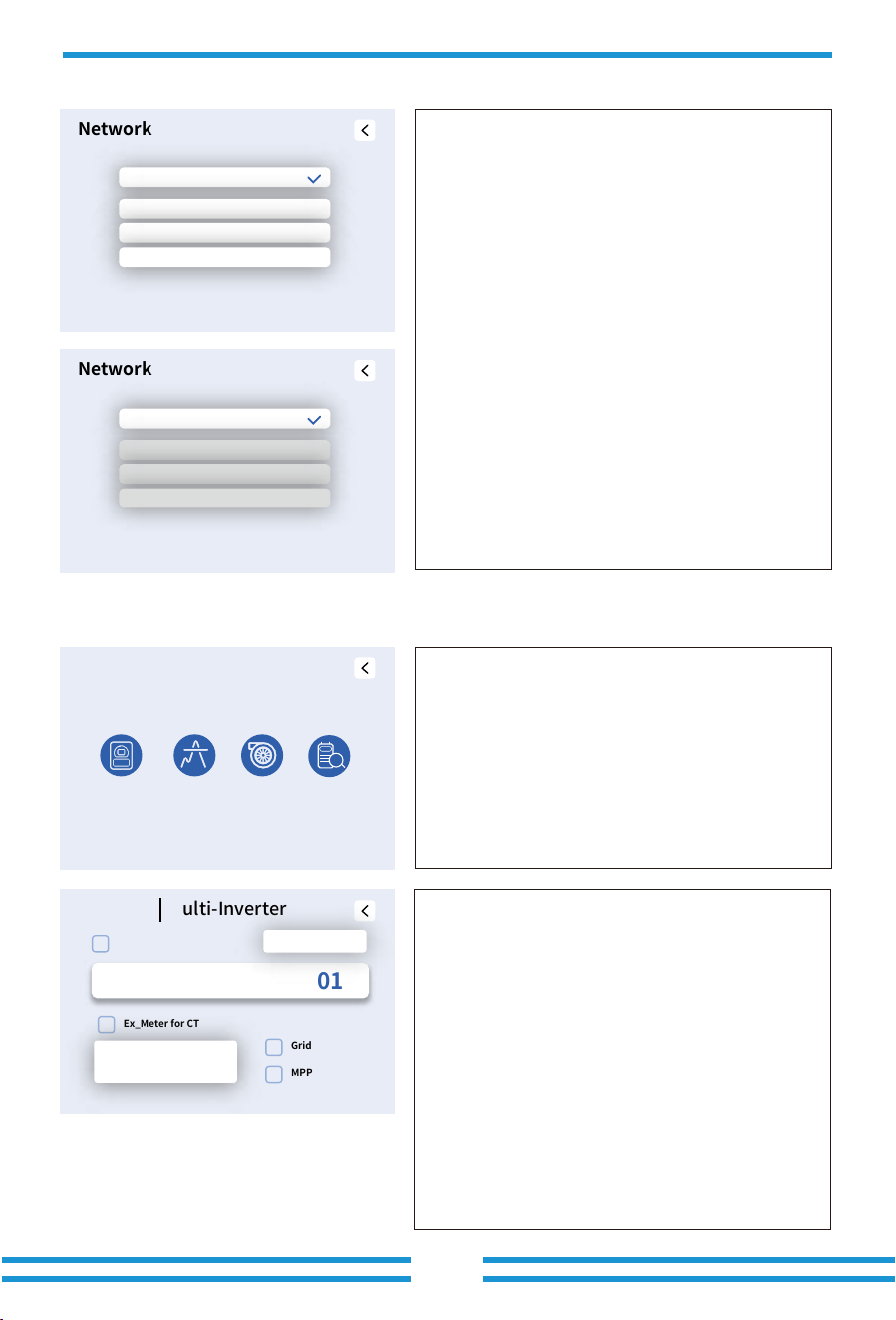
- 50 -
Network
DHCP
IP Address
Subnet Mask
Gateway
192.168.18.19
255.255.255. 0
192.168.18.1
Network
Manual
IP Address
192.168.18.19
Subnet Mask
255.255.255. 0
Gateway
192.168.18.1
Advance
Multi-
Inverter
P-Shave Wind
Turbine
CT
Check
5.12 Network Menu
5.13 Advanced Menu
Click the 'Network' item on the 'Setting' page to enter this page.
Mannual: Manually configure a static IP address, subnet mask,
and gateway for the hybrid inverter based on the local network
router settings.
DHCP: The LAN router automatically assigns an IP address,
subnet mask, and gateway to the hybrid inverter according to
its configuration.
Note: This function is used for communication with the upper
computer monitoring software based on the Modbus TCP
protocol.
Click the 'Advance' item on the 'Setting' page to enter this page,
this page contains 4 sub-settings.
Advance
Multi-Inverter
Parallel
Ex_Meter for CT
Grid Tie Meter2
MPPT_Scan
Slave 01
Meter Select
No Meter
Baud Rate
115200
Parallel: Enable this function when several same model hybrid inverters are
connecting in parallel.
Set this inverter as the master inverter to serve as the control hub of the
parallel system, responsible for coordinating the synchronous operation
of all inverters in the system and ensuring the stability and efficiency of
energy flow, mode switching, and load distribution.
Slave: Set this inverter as a slave inverter to receive control commands
from the master inverter and maintain synchronization with it.
①: The Modbus address of each inverter, should be different.
Baud Rate: The rate at which inverter transmits data.
Note: In a system with multiple inverters operating in parallel, if one
inverter stops output due to a fault, it typically triggers all other inverters in
the parallel system to report faults and cease output as well.
Ex_Meter For CT: When the CT feeder length is insufficient or the CT range
is inadequate, a meter can be used as an alternative. The meter must be of a
matched model and procured through official channels to ensure
compatibility.
Grid Tie Meter2: When there are one or more grid-tied inverters AC coupled
on the grid or load port side of the hybrid inverter, and external meter is
installed for this/these grid-tied inverters, it is necessary to enable this
function to upload the data of the external meter to the hybrid inverter to
ensure that the power consumption data of the load is correct.
MPPT Scan:
After enabling this function, MPPT will perform I-V curve
scanning every 5 minutes to find the maximum power point again and
eliminate MPPT failure caused by shadows.
①
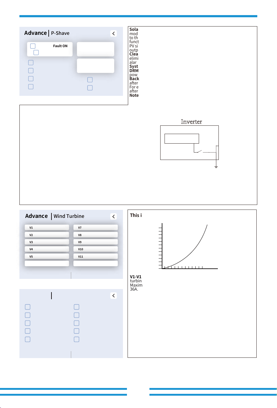
- 51 -
Asymmetric phase feeding:
When the loads connected to the Load port have an unbalanced distribution on the three phases
and the inverter is working in on-grid mode, enabling this function will ensure an equal power absorption from the three phases
of grid.
CEI Report:
Invalid. Only for inverters not exceed 11.08kW, output a self-test report according to Italian CEI 0-21 standards.
Island Enable:
Enable islanding protection mechanism. When checked, the inverter will activate the islanding protection
function. Upon grid power failure, the inverter can quickly detect the loss of grid and automatically disconnect its internal relays,
thereby isolating itself from the grid to prevent the formation of an "islanding effect".
Solar Arc Fault ON(Optional):
This function is optional. Some
models do not have this function, and the specific details are subject
to the hardware version of the inverter received. After enabling this
function, the inverter will detect whether there is a arcing fault on the
PV side. If arcing occurs, the inverter will report a fault and stop
outputting power.
Clear Arc_Fault(Optional):
After the arc fault on the PV side is
eliminated, enabling this function can eliminate the arc fault
alarm of the inverter and restore normal operation of the inverter.
System selfcheck:
Disable. this is only for factory.
DRM:
Demand response mode, receive external commands for active
power scheduling and reactive power scheduling.
Backup Delay:
When the grid cuts off, the inverter will output power
after the set time.
For example, backup delay: 600s. the inverter will give output power
after 600s when the grid cuts off.
Note: for some old FW version, this function is not available.
CT Ratio:
The ratio of the rated primary current to the rated
secondary current of the current transformer multiplied by 100.
L1 L2 L3 N
Load port
Inverter
Shell
Relay
Ground cable
This is for Wind Turbine
16.5
0
310
I/A
U/V
V1-V12: Use 12 points to fit the U/I curve output by the wind
turbine controller.
Maximum input voltage is 850V and maximum input current is
36A.
DC1/2/3/4/5/6/7/8/9/10/11/12 for Wind Turbine:
When checked, it indicates that this MPPT channel is used to
connect to the wind turbine controller.
Advance
Wind Turbine
DC V/I
DC1 for Wind Turbine DC6 for Wind Turbine
DC2 for Wind Turbine DC7 for Wind Turbine
DC3 for Wind Turbine DC8 for Wind Turbine
DC4 for Wind Turbine DC9 for Wind Turbine
DC5 for Wind Turbine DC10 for Wind Turbine
Advance
Wind Turbine
V1 V7
V2 V8
V3 V9
V4 V10
V5 V11
V6 V12
DC V/I
Neutral to earth bonding:
When the "Neutral to Earth Bonding" function is enabled, and the inverter operates in off-grid
mode, the internal relay between neutral (load port N) and protective earth (PE) will close, bonding the neutral line to the
inverter ground.
Note: If this function is enabled, the inverter shell must be reliably
grounded. Failure to do so may result in an electric shock hazard
upon contact with the inverter shell.
The parameter name has been changed, and the corresponding
parameter name in the old version firmware is "Signal island mode".
Advance
P-Shave
Solar Arc Fault ON
0 ms
0:1
System Selfcheck
DRM
Neutral to earth bonding
Asymmetric phase feeding
Island Enable
CEI Report
Clear Arc_Fault
Backup Delay
CT Ratio
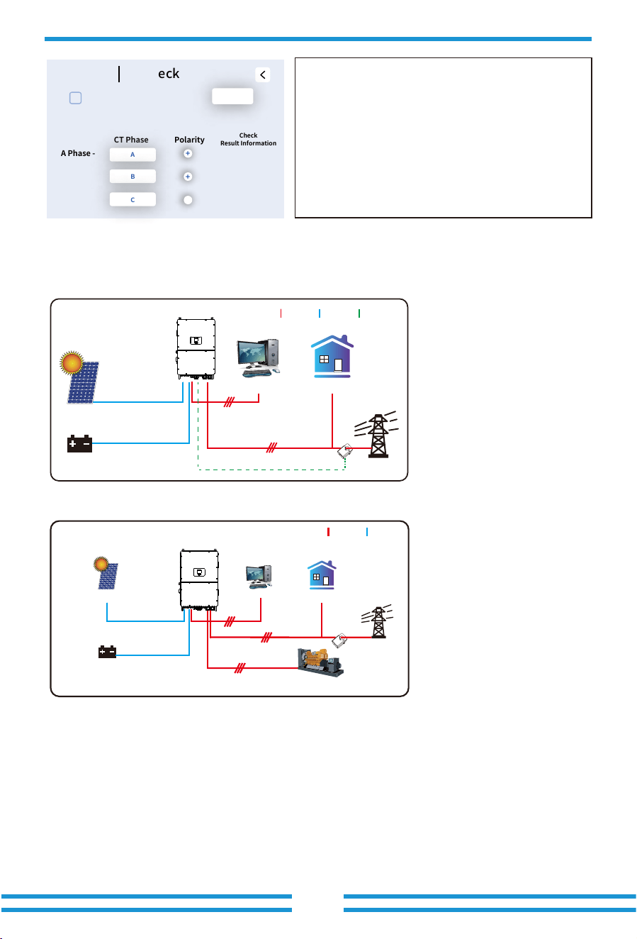
Advance
CT Check
CT Check
CT Phase Polarity
Check
Result Information
A Phase -
Start
A
+
B Phase -
B
+
C Phase -
C
+
6. Mode
Mode I:Basic
Grid
Backup Load On-Grid Home Load
CT
Battery
Solar
AC cable DC cable
COM cable
Grid
Backup Load
On-Grid Home Load
Battery
Solar
CT
AC cable DC cable
Generator
Mode II: With Generator
Note: When using the GEN port as the "generator input" port, the
relays on the grid port and GEN port of the inverter will not be
closed simultaneously. The relays on the GEN port will only be
closed when the inverter is running in off-grid mode.
- 52 -
CT Check: Inverter will perform self check on external CT and return the
test results.
Start: Starting CT self-test.
CT phase: The actual CT in the current phase occupies which phase's
corresponding CT terminals.
Polarity: Whether the secondary side feeder polarity of the CT on the CT
terminal is reversed — "+" indicates correct polarity, "-" indicates reversed
polarity.
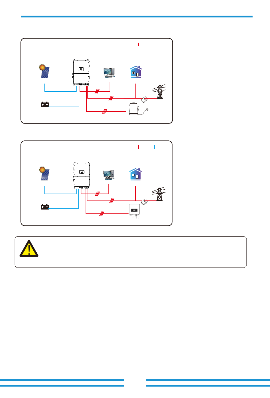
7. Warranty
- 53-
The 1st priority power of the system is always the PV power, then 2nd and
3rd priority power will be the ba�ery bank or grid according to the se�ngs.
The last power backup will be the Generator if it is available.
Grid
Backup Load
On-Grid Home Load
Battery
Solar
CT
AC cable DC cable
Smart Load
Mode III: With Smart-Load
Grid
Backup Load On-Grid Home Load
Battery
Solar
On-Grid+AC couple
AC cable DC cable
On-Grid Inverter
Mode IV: AC Couple
CT
As to Warranty terms, please refer to 《General Warranty Agreement - DEYE》.
Under the guidance of our company, customers return our products so that our company can
provide service of maintenance or replacement of products of the same value. Customers need to
pay the necessary freight and other related costs. Any replacement or repair of the product will
cover the remaining warranty period of the product. If any part of the product or product is
replaced by the company itself during the warranty period, all rights and interests of the
replacement product or component belong to the company.
Factory warranty does not include damage due to the following reasons:

- 54 -
8. Troubleshooting
· Damage during transportation of equipment;
· Damage caused by incorrect installation or commissioning;
· Damage caused by failure to comply with operation instructions, installation instructions or
maintenance instructions;
· Damage caused by attempts to modify, alter or repair products;
· Damage caused by incorrect use or operation;
· Damage caused by insufficient ventilation of equipment;
· Damage caused by failure to comply with applicable safety standards or regulations;
· Damage caused by natural disasters or force majeure (e.g. floods, lightning, overvoltage,
storms, fires, etc.)
In addition, normal wear or any other failure will not affect the basic operation of the product.
Any external scratches, stains or natural mechanical wear does not represent a defect in the
product.
Perform troubleshooting according to the solutions in the table below. Contact the
after-sales service if these methods do not work.
Collect the information below before contacting the after-sales service, so that the problems
can be solved quickly.
• Inverter information like serial number, firmware version, installation date, fault time, fault
frequency, etc.
• Installation environment, including weather conditions, whether the PV modules are
sheltered or shadowed, etc. It is recommended to provide some photos and videos to assist
in analyzing the problem.
• Utility grid situation.
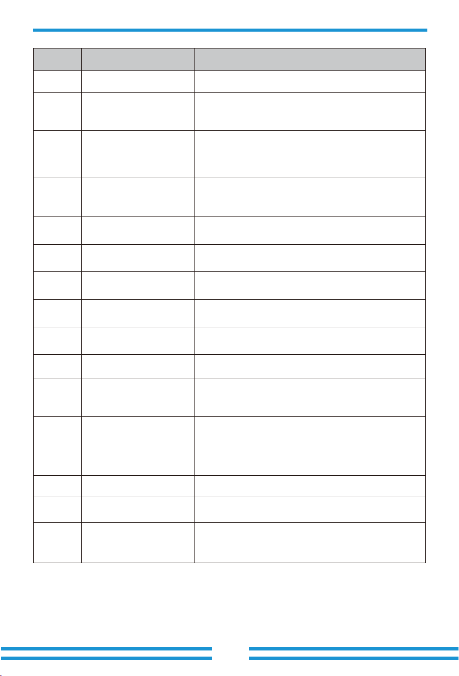
- 55 -
Error code
Meter_offline_warn
CT_WRONG_direction_warn
Meter communication failure
Check whether the meter has successful communication
and whether the wiring is normal.
W�� Reserved
W�� FAN_IN_Warn
�. Check the operating status of the fan.
�. If the fan is running abnormally, open the cover of the
inverter to check the connection of the fan.
W��
W��
W��
Grid_phase_warn
�. Check the phase sequence connection of the power grid.
�. Try to change the grid type, �, ���/���.
�. If there is still no solution to check the wiring at the grid
end.
Check whether the arrow on CT's case point to the inverter or
not , and check if the installation location of CTs are correct.
CT_Notconnect_warnW��
Check whether the wires of CTs are connected correctly or
not.
FAN_OUT�_WarnW��
Check whether the FAN are connected correctly and
operating normally.
FAN_OUT�_WarnW��
Check whether the FAN are connected correctly and
operating normally.
FAN_OUT�_WarnW��
Check whether the FAN are connected correctly and
operating normally.
�. Measure whether the grid port voltage is too high.
�. Check whether the AC cable is too thin to carry current.
Battery_comm_warnW��
Abnormal battery communication
�. Check whether the BMS connection is stable.
�. Check whether the BMS data is abnormal.
Parallel_comm_warnW��
Unstable parallel communication
�. Check the connection of the parallel communication line.
Please do not wind the parallel communication line with
other cables.
�. Check whether the parallel dip switch is on.
VW_activateW��
Description Solutions
F�� DC_Inversed_Failure
Check the PV input polarity.
F�� DC_Insulation_Failure
Check whether the PV is grounded, secondly, check whether
the impedance of the PV to the ground is normal.
F�� GFDI_Failure
�.Check whether the PV modules are grounded.
�. Check whether the impedance of the PV to the ground is
normal, whether there is leakage current.
- 56-
Error code
F�� DCDC�_START_Failure
F�� Working_Mode_Change
F�� AC_OverCurr_SW_Failure
F�� GFCI_Failure
F�� Tz_AC_OverCurr_Fault
The BUS voltage can’t be reached by PV or battery.
�. Switch off the DC switches and restart the inverter.
The BUS voltage can’t be reached by PV or battery.
�. Switch off the DC switches and restart the inverter.
F�� GFDI_Ground_Failure Check whether the PV is grounded.
F�� IGBT_Failure Restart the inverter � times and restore the factory settings.
F�� AuxPowerBoard_Failure
�. First check whether the inverter switch is open.
�. Restart the inverter � times and restore the factory settings.
F�� AC_MainContactor_Failure Restart the inverter � times and restore the factory settings.
F�� EEPROM_Read_Failure Restart the inverter � times and restore the factory settings.
Restart the inverter � times and restore the factory settings
F�� EEPROM_Write_Failure
�. When the grid type and frequency have changed it will
report F��.
�. When the battery mode has been changed to "No battery"
mode, it will report F��.
�. For some old FW version, it will report F�� when the
system's work mode has been changed.
�. Generally, this error will disappear automatically.
�. If it remains the same, turn off DC and AC switches for one
EEPROM_Write_Failure
minute, then turn on the DC and AC switches.
AC side over current fault
�. Please check whether the backup load power and common
load power are within the range.
�. Restart and check whether it is normal.
Leakage current fault
�. Check the PV side cable ground connection.
�. Restart the system �-� times.
AC side over current fault
�. Please check whether the backup load power and
commonload power are within the range.
�. Restart and check whether it is normal.
F�� Tz_Integ_Fault Restart the inverter � times and restore the factory settings.
F�� DCDC�_START_Failure
F�� AC_SlaveContactor_Failure Restart the inverter � times and restore the factory settings.
F�� DC_OverCurr_Failure Restart the inverter � times and restore the factory settings.
F�� Tz_PV_OverCurr_Fault
�. Check the PV connection and whether the PV is unstable.
�. Restart the inverter � times.
Description Solutions
- 57 -
Error code
F��
Tz_EmergStop_Fault
Remotely shutdown
It means the inverter is remotely controlled.
F�� Tz_GFCI_OC_Fault
Leakage current fault
�. Check PV side cable ground connection.
�. Restart the system �~� times.
F�� DC_Insulation_Fault
F�� BusUnbalance_Fault
PV isolation resistance is too low
�. Check the connection of PV panels and inverter is firm and
correct.
�. Check whether the PE cable of inverter is connected to
ground.
F�� DC_Feedback_Fault Restart the inverter � times and restore the factory settings.
F�� DC_Insulation_Fault Restart the inverter � times and restore the factory settings.
�. Please wait for a while and check whether it is normal.
�. When the load power of � phases has a big different, it will
report the F��.
� .When there's DC leakage current, it will report F��.
�. Restart the system �~� times.
F�� DCIOver_M�_Fault Restart the inverter � times and restore the factory settings.
F��
Parallel_Comm_Fault
�. When inverters are connected in parallel, check the parallel
communication cable connection and hybrid inverter
communication address setting.
�. During the parallel system startup period, inverters will
report F��. But when all inverters are in ON status, it will
disappear automatically.
F�� AC_MainContactor_Fault
F�� AC_SlaveContactor_Fault
F�� DCIOver_M�_Fault
�. Check whether the grid orientation is correct,
�. Restart the inverter � times and restore the factory settings
Restart the inverter � times and restore the factory settings.
Restart the inverter � times and restore the factory settings.
F�� AC_OverCurr_Fault
�. Check whether the grid current is too large.
�. Restart the inverter � times and restore the factory settings.
F�� Tz_HV_Overcurr_Fault
BUS over current
�. Check the PV input current and battery current setting.
�. Restart the system �~� times.
F�� Tz_Dc_OverCurr_Fault
DC side over current fault
�. Check PV module connection and battery connection;
�. When in the off-grid mode, starting the inverter under a high
power load may report F��. Please reduce the load power
connected.
�. If it remains the same, turn off DC and AC switches for one
minute, then turn on the DC and AC switches.
Description Solutions
F�� AC_Overload_Fault
Check the backup load connection, make sure it is within the
allowed power range.
- 58 -
F��
AC_OverFreq_Fault
Grid frequency out of range
�. Check whether the frequency is in the range of the
specification or not.
�. Check whether AC cables are firmly and correctly
connected.
F�� AC_UnderFreq_Fault
Grid frequency out of range
�. Check whether the frequency is in the range of the
specification or not.
�. Check whether AC cables are firmly and correctly
connected.
Error code
F�� INT_DC_OverCurr_Fault Inverter DC overcurrent, restart the inverter.
F�� Reserved
F�� Reserved
F�� AC_UV_OverVolt_Fault
Grid voltage out of range
�. Check the voltage is in the range of specification or not.
�. Check whether AC cables are firmly and correctly
connected.
F�� AC_UV_UnderVolt_Fault
Grid voltage out of range
�. Check the voltage is in the range of specification or not.
�. Check whether AC cables are firmly and correctly
connected.
F�� AC_V_GridCurr_DcHigh_Fault Restart the inverter � times and restore the factory settings.
F�� AC_U_GridCurr_DcHigh_Fault Restart the inverter � times and restore the factory settings.
F�� Reserved
F�� INT_AC_OverCurr_Fault Inverter AC overcurrent, restart the inverter.
F�� AC_NoUtility_Fault
Check the grid voltage and frequency, whether the connection
of the power grid is normal.
F�� Reserved
F�� Reserved
Description Solutions
F�� Parallel_system_Stop
F�� Parallel_Version_Fault
Check the hybrid inverter work status. If there is at least one
hybrid inverter shutdown, all hybrid inverters will report F��
fault.
�. Check whether the inverter version is consistent.
�. Please contact us to upgrade the software version.
- 59 -
Error code Description Solutions
F�� DC_VoltHigh_Fault
F�� DC_VoltLow_Fault
BUS voltage is too high
�. Check whether battery voltage is too high.
�. check the PV input voltage, make sure it is within the
allowed range.
Check wether the temperature data of BMS is too high.
Check whether the voltage and frequency of the generator
are normal, and then restart.
F�� Reserved
F�� GEN_FAULT
Check whether the switch of the inverter is turned on, restart
the inverter, and restore the factory settings.
F�� INVERTER_Manual_OFF
F�� Battery_Temp_High_Fault
BUS voltage is too low
�. Check whether battery voltage is too low.
�. If the battery voltage is too low, use PV or grid to charge
the battery.
F�� Battery_Comm_Lose
�. It means that the communication between the hybrid
inverter and the battery BMS is disconnected when
"BMS_Err-Stop" is active.
�. To avoid this error, disable "BMS_Err-Stop" item on the LCD.
F��
DRMs_Stop
F�� ARC_Fault
F��
Heatsink_HighTemp_Fault
�. ARC fault detection is only for US market.
�. Check PV module cable connection and clear the fault.
F�� BAT�_VoltHigh_Fault
�. Check the battery � terminal voltage is high.
�. Restart the inverter � times and restore the factory settings.
F�� BAT�_VoltHigh_Fault
�. Check the battery � terminal voltage is high.
�. Restart the inverter � times and restore the factory settings.
F�� BAT�_VoltLow_Fault
�. Check the battery � terminal voltage is low.
�. Restart the inverter � times and restore the factory settings.
F�� BAT�_VoltLow_Fault
�. Check the battery � terminal voltage is low;
�. Restart the inverter � times and restore the factory settings.
Check the DRM function is active or not.
Heat sink temperature is too high
�. Check whether the working environment temperature is
too high.
�. Turn off the inverter for �� minutes and restart.
Chart 8-1 Fault information
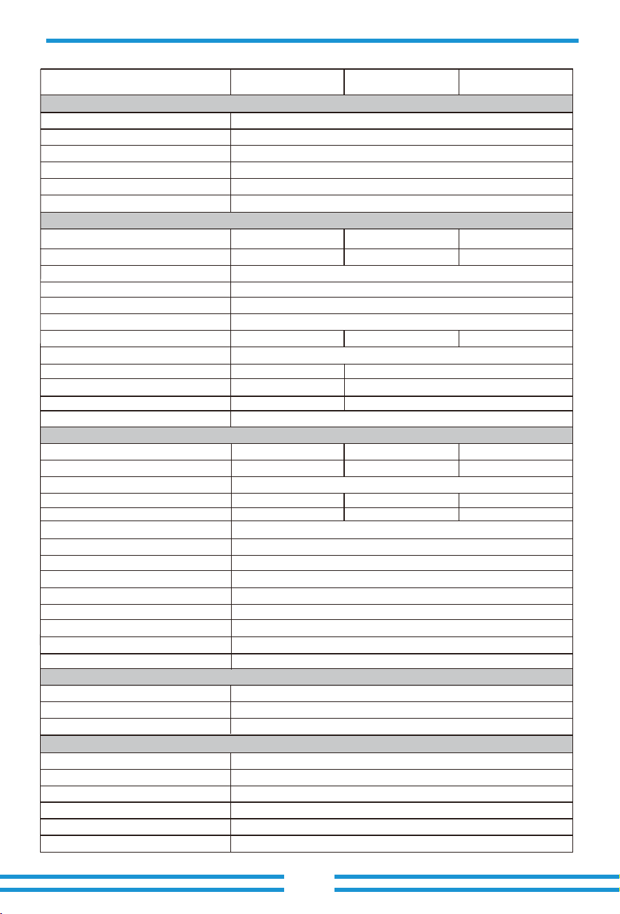
- 60 -
9. Datasheet
Max. AC Input/Output Apparent Power(VA)
Peak Power (off-grid)
(W)
Max. AC Input/Output Current(A)
Model
Battery Input Data
Rated AC Input/Output Current(A)
Battery Type
Battery Voltage Range(V)*
Max. Charging Current(A)
Max. Discharging Current(A)
Charging Strategy for Li-ion Battery
Max. Operating PV Input Current(A)
No. of MPP Trackers/No. of Strings MPP Tracker
Max. Inverter Backfeed Current To the Array
AC Input/Output Data
1.5 time of rated power, 10 S
Lithium-ion
160-1000
Self-adaption to BMS
10/2+2+2+2+2+2+2+2+2+2
0
3L+N+PE
100+100
100+100
Rated AC Input/Output Active Power(W)
Number of Battery Input 2
Full Load MPPT Voltage Range(V)
Rated PV Input Voltage (V)
Equipment Protection
Yes
AC Output Overcurrent Protection
DC reverse polarity protection
Yes
YesAC Output Overvoltage Protection
YesAC Output Short Circuit Protection
Thermal Protection Yes
YesInsulation Impedance detection
98.70%
Efficiency
Max. Efficiency
98.10%Euro Efficiency
>99%
MPPT Efficiency
50Hz/45Hz-55Hz 60Hz/55Hz-65Hz
0.8 leading to 0.8 lagging
Rated Input/Output Grid Frequency/Range
Power Factor Adjustment Range
<0.5% In
DC Injection Current
<3% (of nominal power)
Total Current Harmonic Distortion THDi
Grid Connection Form
220/380V, 230/400V 0.85Un-1.1Un
Rated Input/Output Voltage/Range(V)
Max. Input Short-Circuit Current(A)
PV String Input Data
Max. PV Input Power(W)
Max. PV Input Voltage (V)
Start-up Voltage(V)
MPPT Voltage Range(V)
1000
180
150-850
650
42+42+42+42+42+42+42+42+42+42
63+63+63+63+63+63+63+63+63+63
8/2+2+2+2+2+2+2+2
42+42+42+42+42+42+42+42
63+63+63+63+63+63+63+63
Max. PV access power(W)
Max. Output Fault Current (A)
Max. Output Overcurrent Protection (A)
550
SUN-100K-SG02HP3
-EU-GM10
100000
110000
151.6/145.0
310-850
160000
166.7/159.5
200000
SUN-100K-SG02HP3
-EU-GM8
100000
110000
151.6/145.0
390-850
160000
166.7/159.5
200000
450
SUN-125K-SG02HP3
-EU-GM10
125000
135000
189.4/181.2
390-850
200000
204.6/195.7
250000
180-1000PV Input Voltage Range(V)*
250
Max. Continuous AC Passthrough (grid to load)(A)
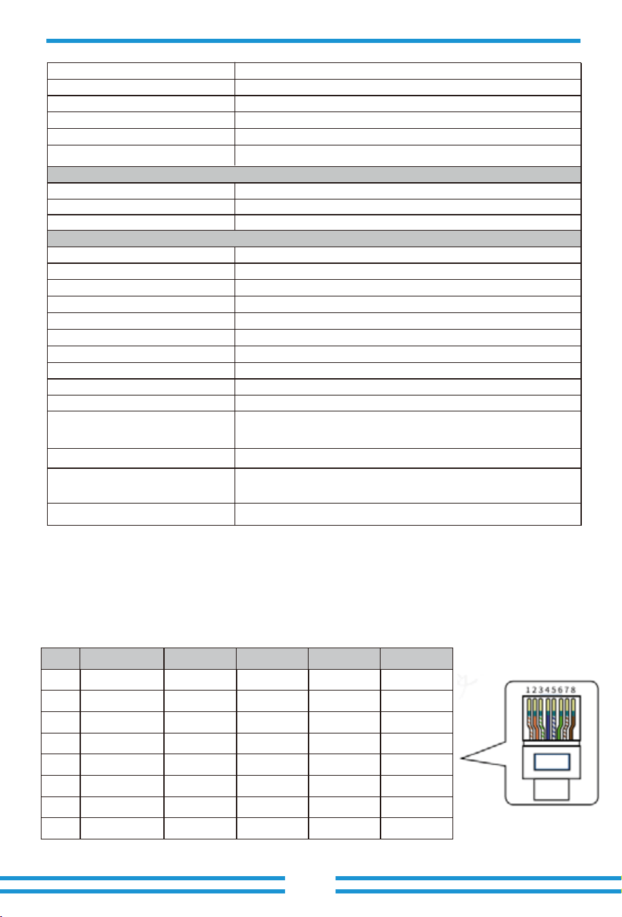
- 61 -
10. Appendix I
Definition of RJ45 Ports
1
2
3
4
5
6
7
8
No.
Orange&White
Orange
Blue
Blue&White
Green
Green&White
Brown&White
Brown
Color
485_B
485_A
CAN-H1
CAN-L1
GND_485
GND_485
485_A
485_B
BMS1
485_B
485_A
CAN-H2
CAN-L2
GND_485
GND_485
485_A
485_B
BMS2
485_B
485_A
485_B
485_A
GND_COM
GND_COM
⸺
⸺
Meter
485_B
485_A
⸺
⸺
GND_485
GND_485
485_A
485_B
RS485
YesDC Component Monitoring
Surge Protection Level
Anti-islanding protection
DC Switch
Residual Current Detection
General Data
Grid Regulation
Safety EMC/Standard
Interface
Operating Temperature Range
Permissible Ambient Humidity
Permissible Altitude
Weight(kg)
Cabinet size(W*H*D) [mm]
Warranty
Noise
Ingress Protection(IP) Rating
Inverter Topology
Over Voltage Category
Type of Cooling
5 Years/10 Years
the Warranty Period Depends the Final Installation Site of Inverter,
More Info Please Refer to Warranty Policy
TYPE II(DC),TYPE II(AC)
Yes
Yes
Yes
-40 to +60℃, >45℃ Derating
3000m
0-100%
Intelligent air cooling
161.7
Installation Style Wall-mounted
734W×1091H×344D (Excluding connectors and brackets)
≤ 65 dB
IP 65
Non-Isolated
OVC II(DC), OVC III(AC)
IEC 61727,IEC 62116,CEI 0-21,EN 50549,NRS 097,RD 140,
UNE 217002,OVE-Richtlinie R25,G99,VDE-AR-N 4105
IEC/EN 61000-6-1/2/3/4, IEC/EN 62109-1, IEC/EN 62109-2
RS232, RS485, CAN
Monitor Mode
Communication Interface
GPRS/WIFI/Bluetooth/4G/LAN (optional)
LCD+LEDDisplay
OptionalArc fault circuit interrupter (AFCI)
* Battery Voltage Range: Please refer to the 'Approved Battery List' for the allowable range of battery
module quantity for a set of batteries to ensure the normal operation of the system.
* PV Input Voltage Range:To ensure the system operates at optimal performance, it is recommended to
maintain the open-circuit voltage (Voc) of the PV strings below 850V.
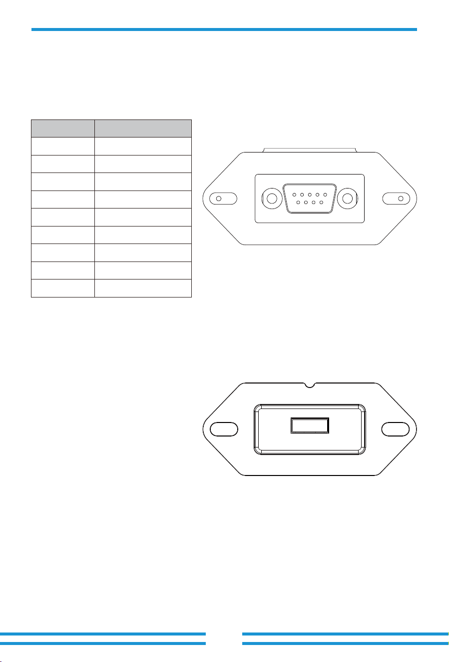
- 62 -
RS���
USB
DB� (RS���)
12345
6789
This model of inverter has two types of logger interfaces, DB� and USB. Please refer to the
actual inverter received for the actual interface type.
�
No.
D-GND
RS���
�
�
�
�
�
TX
�
��Vdc
�
RX
�
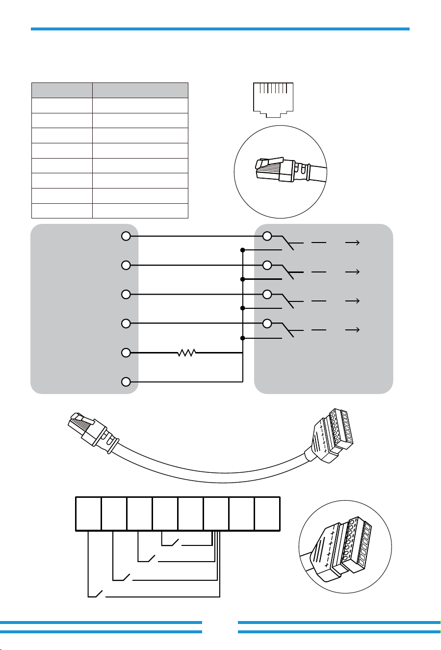
- �� -
DRM:In Germany, the grid company uses the Ripple Control Receiver to convert the grid dispatching
signal and send it as a dry contact signal.The inverter can control power output according to the
local preset instruc�ons as shown below.
12345678
87654321
1
No.
DI 1
DRM
2 DI 2
3 DI 3
DI 4
4
5
6 GND
REF
7 Reserved
8 Reserved
Defini�on of RJ45 Port Pin for DRM
Inverter RCR
12345678
1
K 1
K 2
K 3
K 4
2 3 4 5 6 7 8
K 1 0%
PIN 6 GND
PIN 5 REF
PIN 4 DI 4
PIN 3 DI 3
PIN 1 DI 1
PIN 2 DI 2
K 2 30%
K 3 60%
K 4 100%
15K
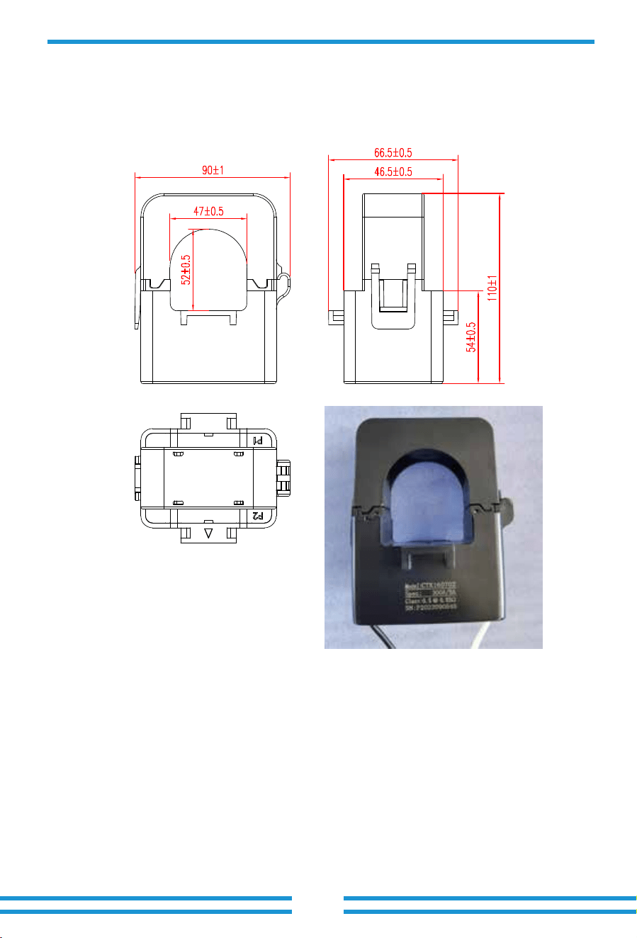
- 64 -
1. Split Core Current Transformer (CT) dimension: (mm)
2. Secondary output cable length is 4m.
11. Appendix II
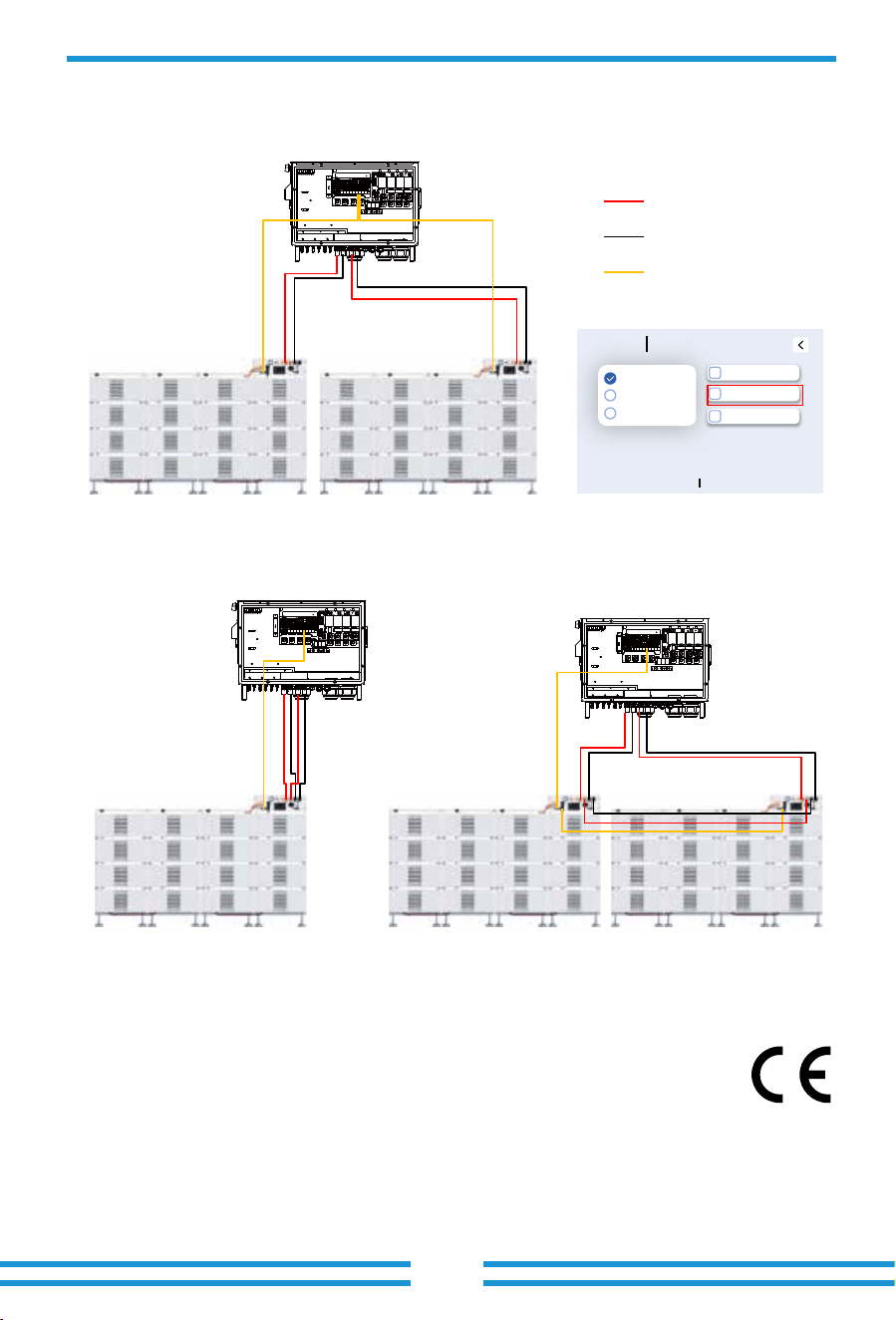
12. Appendix III
13. EU Declaration of Conformity
within the scope of the EU directives
· Electromagnetic compatibility ����/��/EU (EMC)
· Radio Equipment Directive (RED) ����/��/EU
· Restriction of the use of certain hazardous substances ����/��/EU (RoHS)
NINGBO DEYE INVERTER TECHNOLOGY CO., LTD. confirms herewith that the products
described in this document are in compliance with the fundamental requirements and other
relevant provisions of the above mentioned directives. The entire EU Declaration of Conformity
and certificate can be found at https://www.deyeinverter.com/download/#hybrid-inverter-�.
CAN to BMS1 of
the inverter
CAN to BMS1 of
the inverter
- 65 -
BMS�
BMS�
Master
Slave
CAN(parallel)
Positive Power line
RJ45 CAN communication line
Negative Power line
When use both the BMS1 port and the BMS2 port of the inverter to communicate with the two different BMS of two sets
of ba�ery, there is no need to enable "Parallel bat1&bat2" func�on.
When only use BMS1 port of the inverter to communicate with the BMS of the ba�ery, and both sets of ba�ery power
ports are used, it's necessary to enable "Parallel bat1&bat2" func�on.If the BMS controller of the ba�ery does not
have two sets of power cable wiring terminals,addi�onal DC BUS or combiner box needs to be used.
Battery
Type
Parameters
Type options
No Battery
Lithium
Use Batt V
Off INV off battery
Parallel bat1&bat2
Gen Force
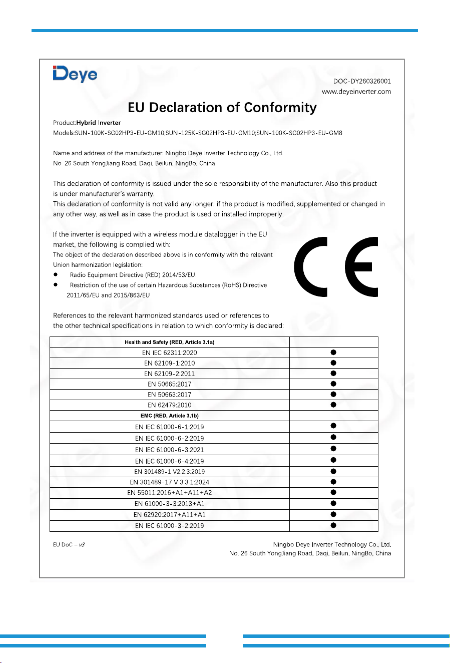
- 66 -
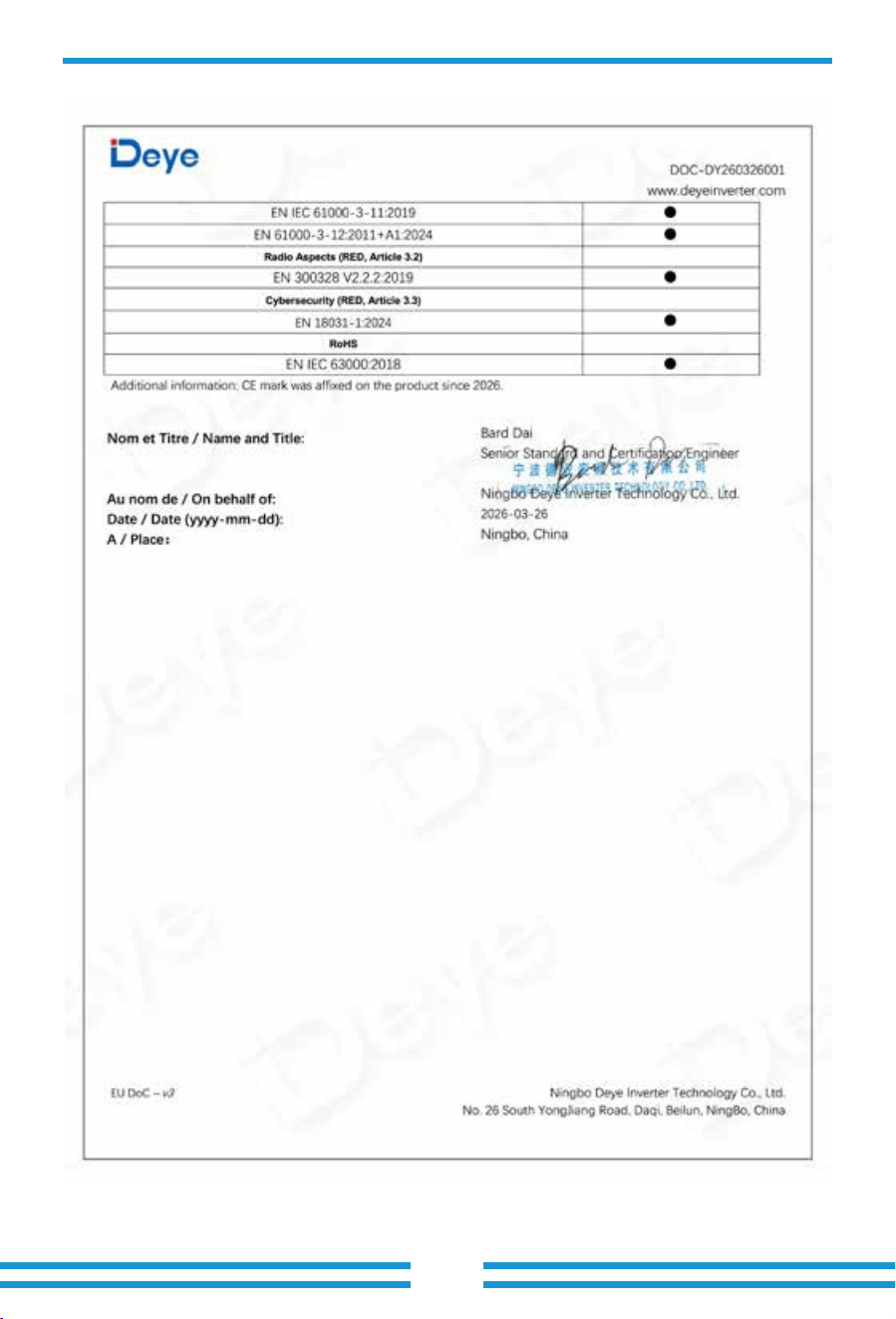
V1.1.0, 2026-05-25
- 67 -

Add.: No.26 South YongJiang Road, Daqi, Beilun, NingBo, China.
Fax.: +86 (0) 574 8622 8852
Tel.: +86 (0) 574 8622 8957
E-mail: [email protected]
Web.: www.deyeinverter.com