User Manual
for S6 Series Hybrid Inverter
Version 1.1, Release Date:01,2025
Applicable models
S6-EH3P8K02-NV-YD-L
S6-EH3P10K02-NV-YD-L
S6-EH3P12K02-NV-YD-L
S6-EH3P15K02-NV-YD-L
S6-EH3P7K02-LV-YD-L
S6-EH3P8K02-LV-YD-L
S6-EH3P9K02-LV-YD-L
Applicable System
Three phase system

Important Notes
Due to the product development,the product specifications and functions are subject to
change.The latest manual can be acquired via https://www.ginlong.com/global.
Every attempt has been made to make this document complete, accurate and up-to-date.
Individuals reviewing this document and installers or service personnel are cautioned,
however, that Solis reserves the right to make changes without notice and shall not be
responsible for any damages, including indirect, incidental or consequential damages
caused by reliance on the material presented including, but not limited to, omissions,
typographical errors, arithmetical errors or listing errors in the material provided in this
document.
Solis accepts no liability for customers' failure to comply with the instructions for
correct installation and will not be held responsible for upstream or downstream systems
Solis equipment has supplied.
The customer is fully liable for any modifications made to the system; therefore, any
hardware or software modification, manipulation, or alteration not expressly approved
by the manufacturer shall result in the immediate cancellation of the warranty.
Given the countless possible system configurations and installation environments, it is
essential to verify adherence to the following:
● There is sufficient space suitable for housing the equipment.
● Airborne noise produced depending on the environment.
● Potential flammability hazards.
● Solis will not be held liable for defects or malfunctions arising from:
● Improper use of the equipment.
● Deterioration resulting from transportation or particular environmental conditions.
● Performing maintenance incorrectly or not at all.
● Tampering or unsafe repairs.
● Use or installation by unqualified persons.
● This product contains lethal voltages and should be installed by qualified electrical
or service personnel having experience with lethal voltages.

01-05
11
36
14
16
17
24
25
11
01
02
36-37
20
27
1.1 Product Overview
………………………………………………………………………………………………………………………………
…………………………………………………………………………………………………………
…………………………………………………………………………………………………………………………………………
……………………………………………………………………………………………
………………………………………………………………………………………………
…………………………………………………………………………………………………………………
………………………………………………………………………………………………………………………
………………………………………………………………………………………………………………
………………………………………………………………………………………………………………………………
…………………………………………………………………
…………………………………………………………………………………………………………………………………
1. Introduction
1.2 Inverter Wire Box and Connection Points
2. Safety & Warning
2.1 Safety
2.2 General Safety Instructions
4. Overview
4.1 Screen
3.9 CT Connection
3. Installation
3.1 Select a Location to Install the Inverter
3.2 Product Handling
3.4 Inverter Wiring Overview
3.6 PV Cable Installation
3.7 Battery Cable Installation
………………………………………………………………………………………………………………………………………
………………………………………………………………………
13
2.3 Notice for Use
13
………………………………………………………………………………………………………………
………………………………………………………………………………………………
………………………………………………………………………………………………
21
3.5 Ground Cable Installation
………………………………………………………………………………………………………
26
3.8 AC Wiring
…………………………………………………………………………………………………………………………
38
…………………………………………………………………………………………………………………………………
5. Commissioning
19
3.3 Mounting the Inverter
…………………………………………………………………………………………………
38
5.1 Pre-Commissioning
………………………………………………………………………………………………………………………………
5.2 Power ON
Contents
2.4 Notice for Disposal
14-35
………………………………………………………………………………………………………………………………
04
…………………………………………………………………………………………………………………
1.5 Product Features
1.3 Packaging
1.4 Tools Required for Installation
3.10 Inverter Communication
3.11 Inverter Remote Monitoring Connection
36
………………………………………………………………………………………………………………………………………
4.2 Keypad
5.3 Power OFF
03
………………………………………………………………………………………………………………………………
38
……………………………………………………………………………………………………………
38-72
…………………………………………………………………………………………………………………
35
………………………………………………………………
11-13
……………………………………………………………………………………………………………
04
………………………………………………………………………………………
49
………………………………………………………………………………………………
5.5 Log in the APP via Bluetooth
36
…………………………………………………………………………………………………………………………
4.3 LED Indicators
37
……………………………………………………………………………
4.4 Inverter built-in Bluetooth description
39
………………………………………………………………………………………………………………
5.4 HMI Screen Setting
1.6 System Description
05
………………………………………………………………………………………………………………
51
5.6 Shutdown procedure
…………………………………………………………………………………………………………
52
5.7 Work Mode and Settings
……………………………………………………………………………………………………
57
5.8 TOU Function Settings
………………………………………………………………………………………………………
58
5.9 Battery Settings
……………………………………………………………………………………………………………………

7. Troubleshooting
…………………………………………………………………………………………………………………
85
90
………………………………………………………………………………………………………………………
8. Specifications
66
……………………………………………………………………………………………………………………………
84
…………………………………………………………………………………………………………………………
6. Maintenance
84
6.1 Smart O&M
……………………………………………………………………………………………………………………………
72
…………………………………………………………………………………………………………………………
5.15 Initial set up
5.16 APP Interface
59
5.10 Battery Functions setting
……………………………………………………………………………………………………
60
5.11 Smart port settings
………………………………………………………………………………………………………………
63
5.12 Grid port settings
………………………………………………………………………………………………………………
64
5.13 Parallel Settings
…………………………………………………………………………………………………………………
64
5.14 Only PV power load function
………………………………………………………………………………………
102
…………………………………………………………………………………………………………………
9. Appendix - FAQs
Contents
1. Introduction
User Manual
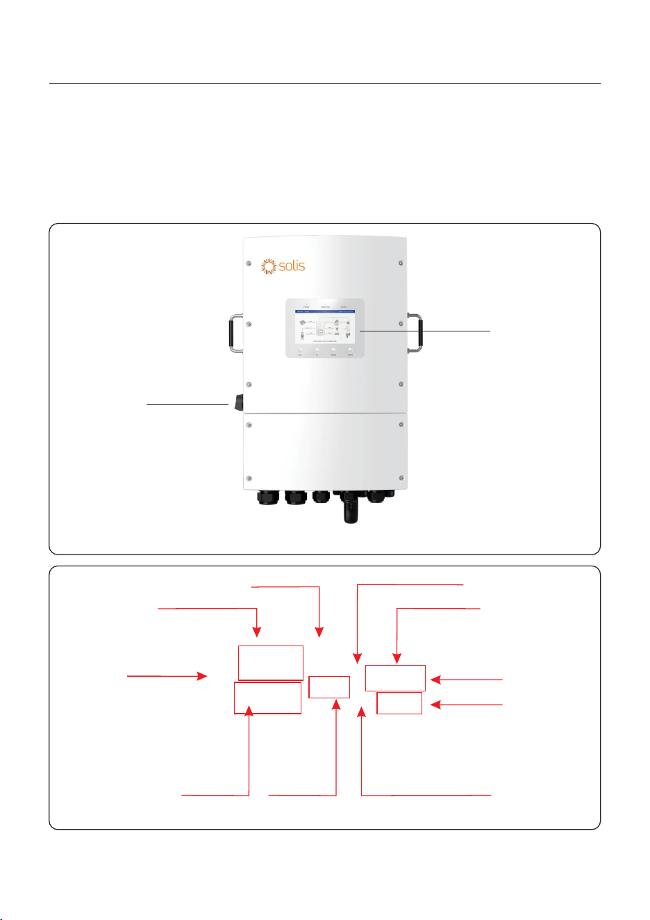
1.1 Product Overview
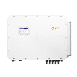
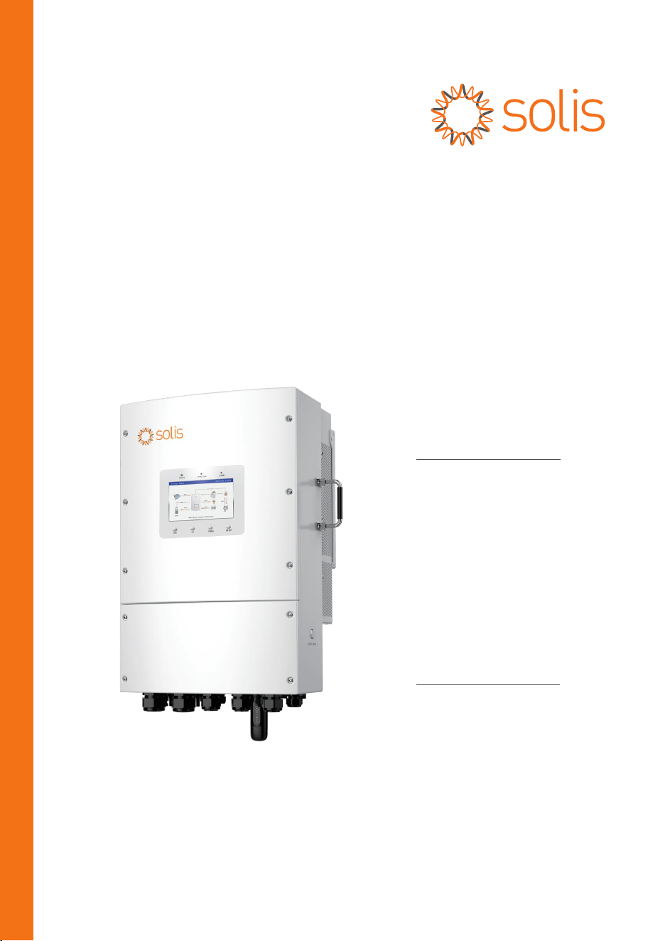
The Solis series is designed for commercial hybrid systems.
The inverter can work with maximize self-consumption and provide backup power if the grid
fails and there is not enough PV power to cover load demand.
The Solis S6 series consists of the following inverter models:
8kW,10kW,12kW,15kW,7kW-LV,8kW-LV,9kW-LV
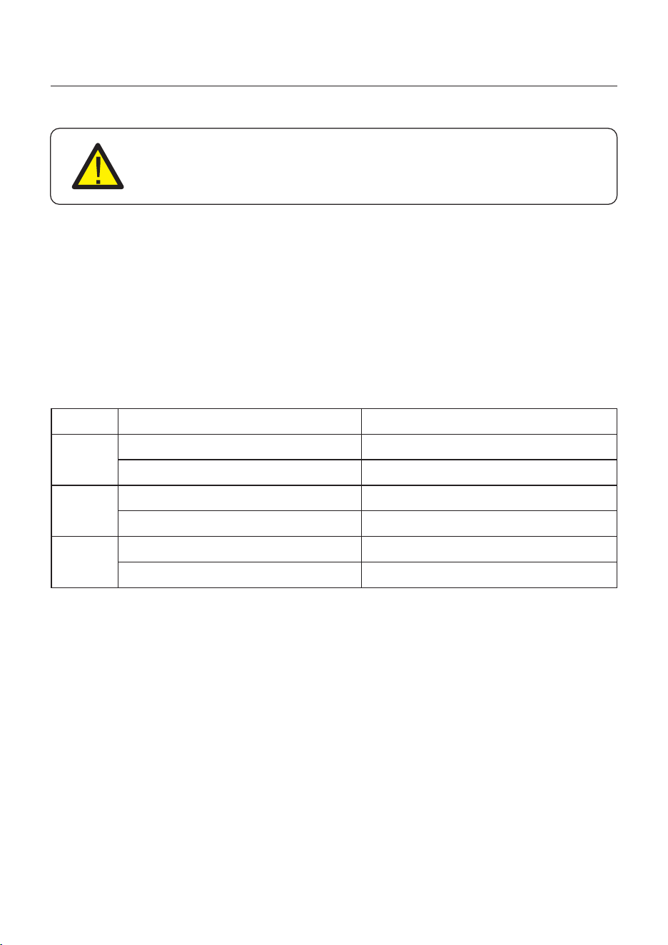
Figure 1.1
Front side view
Figure 1.2
Bottom side view
01
AC Grid Port
AC Backup Port
PV Input
Battery Input
DC Switch
LCD Screen
GEN Port
COM4/5
Datalogger Stick
Antenna
DC Switch
COM2/3
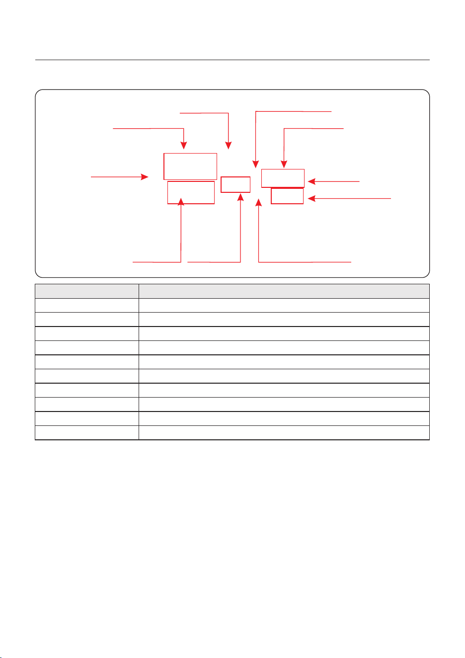
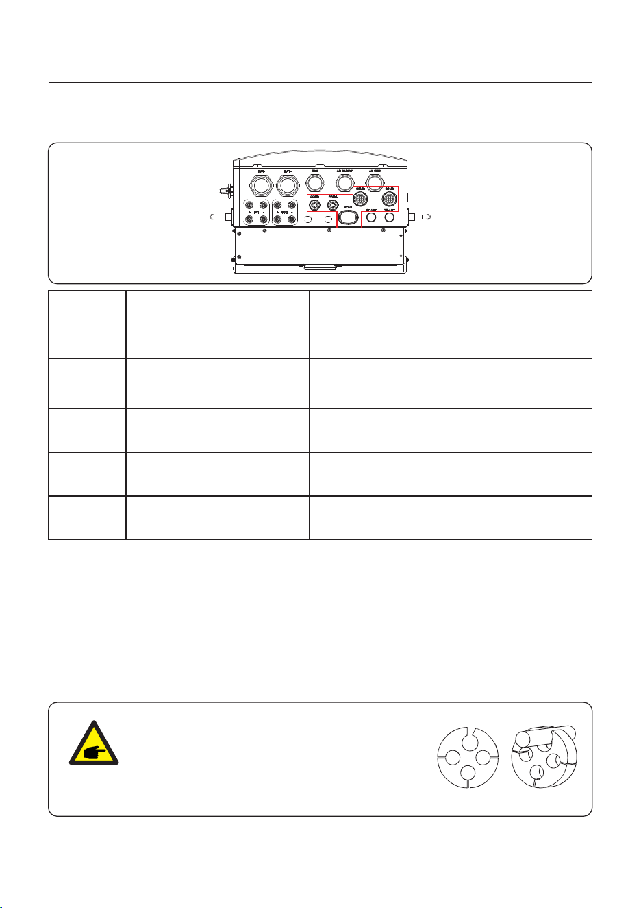
1.2 Inverter Wire Box and Connection Points
Name Description
3. GEN
1. DC Switch
6. PV Input
4. Backup
5. Grid
2. Battery Input
This is the DC disconnect switch for the PV
Conduit for AC conductors to backup loads panel should be connected here
Conduit for AC conductors to the main service panel should be connected here
1. Introduction
User Manual
Conduit for PV conductors should be connected here
Conduit for Battery conductors should be connected here
02
Conduit for AC conductors to generator should be connected here
AC Grid Port
AC Backup Port
PV Input
Battery Input
GEN Port
COM4/5
Datalogger Stick
DC Switch
COM2/3
7. COM4/5
Conduit for CT conductors should be connected here
9. Datalogger Stick Solis data logger gets connected here-only USB version of the loggers will work
Bluetooth Antenna
8. COM2/3
RS485 and CAN communication cables and parallel cables should go through these
10. Bluetooth Antenna
Extends the range of the inverter Bluetooth signal(for system commissiong)
User Manual
1. Introduction
03
Back plate x1
Fastening screw x2
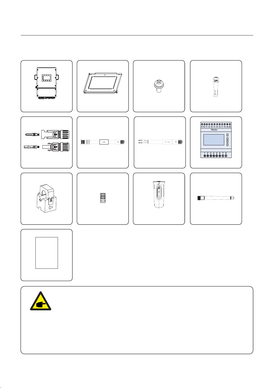
1.3 Packaging
Please ensure that the following items are included in the packaging with your machine:
Inverter x1
Expansion Bolt x4
RJ45 connector x6
CT 3x S2-WL-ST Stick x1
Bluetooth Antenna x1
If anything is missing, please contact your local Solis distributor.
NOTE:
If customer purchases the CT configuration scheme, the attachment only
contains CT.100A/50mA CT; MODEL: ESCT-TA16-100A/50mA.
If the meter configuration plan is purchased, the accessories include CT,
the meter, and the meter communication cable. 40mA Meter+120A/40mA CT;
MODEL:SDM630MCT+ESCT-TA16.
If more than 3 devices are connected in parallel ,you need select a separate
kit. The accessories include CT and the meter.
Separate Kit: 5A Meter+300A/5A CT,MODEL: SDM630MCT V2+ESCT-T50
Parallel cable x1
PV Connector x4
Eastron Meter x1
Meter cable x1
Quick Installation Manual x1
Quick
Installation
Manual
User Manual
1. Introduction
04
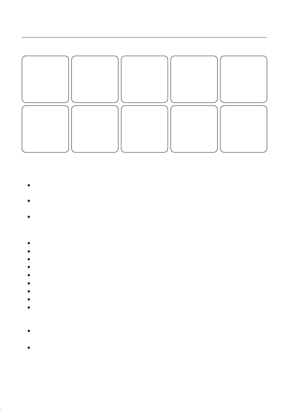
1.4 Tools Required for Installation
Torqx T20 Screwdriver Wire Strippers 12AWG to 6AWG Wire Strippers 20AWG to 10AWG
Drill and Impact Driver
Multimeter (AC/DC amps)
Channel Locks
Technician Screwdriver
LUG Crimping Tool
Torque Screwdriver
MC4 Crimping Tool
1.5 Product Features
Integrated 2 MPPTs with 3(8-12K)/4(15K) strings, suitable for residential rooftop
installations with multiple array orientations.
Compatible with multiple brands of battery models giving customers multiple battery
options.
Exquisite LED Indicators with built in Bluetooth to provide local operation without Internet.
Outstanding Performance
20A input current adapted to high current PV Panel.
2 backup function achieves intelligent energy use plan.
6 customizable charge/discharge periods.
Up to 180A/8K,220A/10K,250A/12K,290A/15K max charge/discharge current.
Seamless switching when the utility grid loses power.
Support start/stop control and status monitoring of genset.
AC coupling to upgrade existing PV plant.
Intelligent APP&7-inch colorful touch screen acheives visual and easy operation.
Battery friendly with a large selection of brands.
Intelligent Function
Safe&Reliable
Safety protection with integrated AFCI function, which actively detects arc faults in the
PV Array.
Multiple battery protection function.
User Manual
1. Introduction
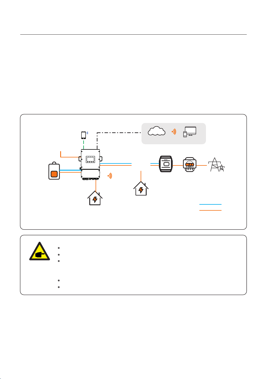
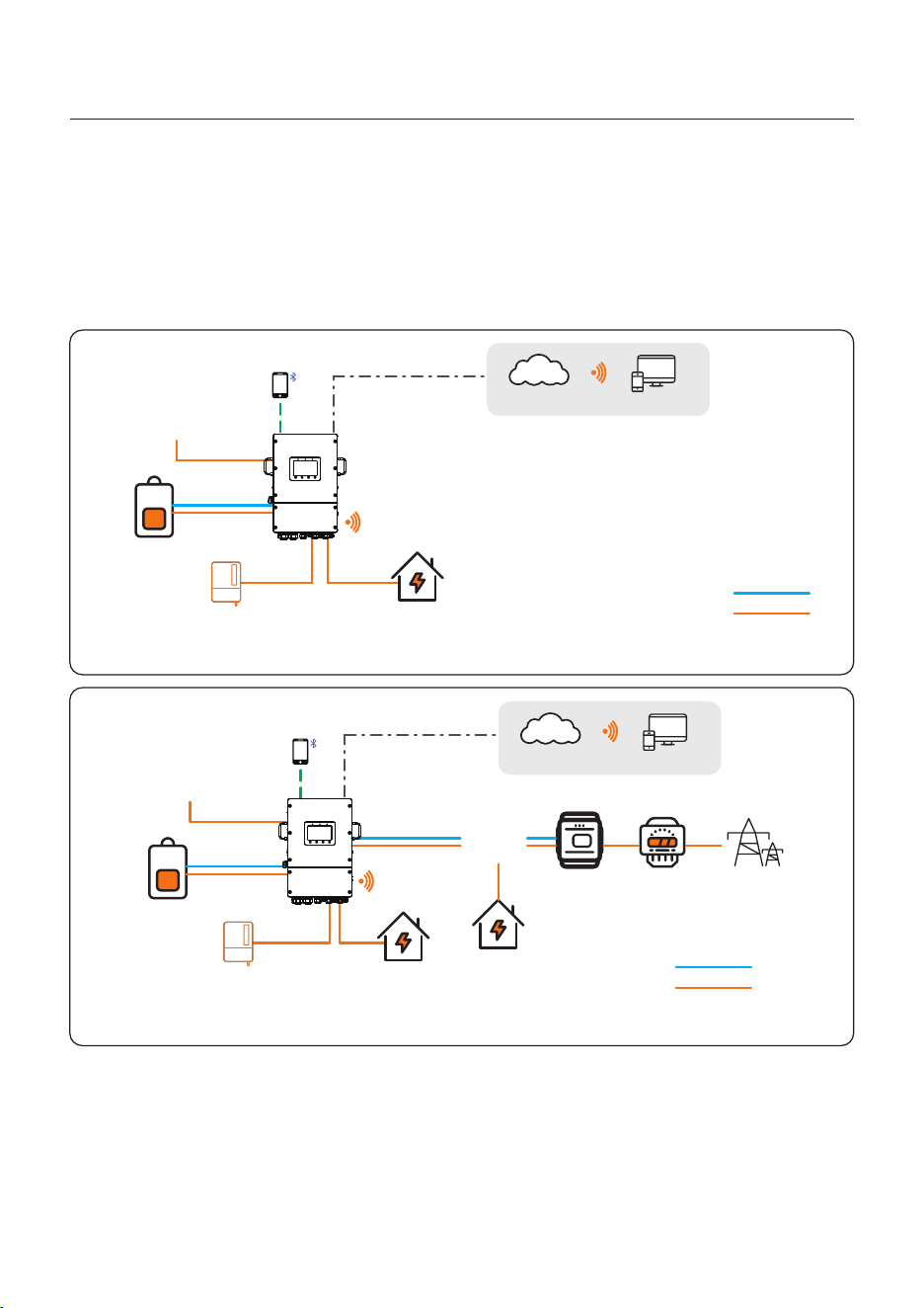
The single system consists of PV module, battery, hybrid inverter, CT or smart meter.
The PV Module converts solar energy into electric energy, which is then converted by the
inverter to charge the battery or power loads or feed into the grid.
User can connect heat pump, existing PV plant, generator and ATS according to the
actual scenario.
The system has three working modes: self-use mode, feed in priority mode and off-grid
mode.
1.6.1 Single system
NOTE:
If the CTs are connected, the Smart meter is not essential.
you can choose CT scheme or Meter scheme deliver with inverter.
In the event of a power outage on the grid, the system will seamlessly
transition into off-grid mode, providing power exclusively to essential backup
loads.
When the grid recovers, the system switches back to the on-grid operation.
Supports heat pump control, only when it has a SG Ready label.
Figure 1.3 Single System
Battery
PV Module
Backup Load
Grid Load
CT/Smart Meter Power Meter
SolisCloud
APP Web
Grid
Hybrid Inverter
Power Line
Signal Line
Phone
1.6 System Description
05
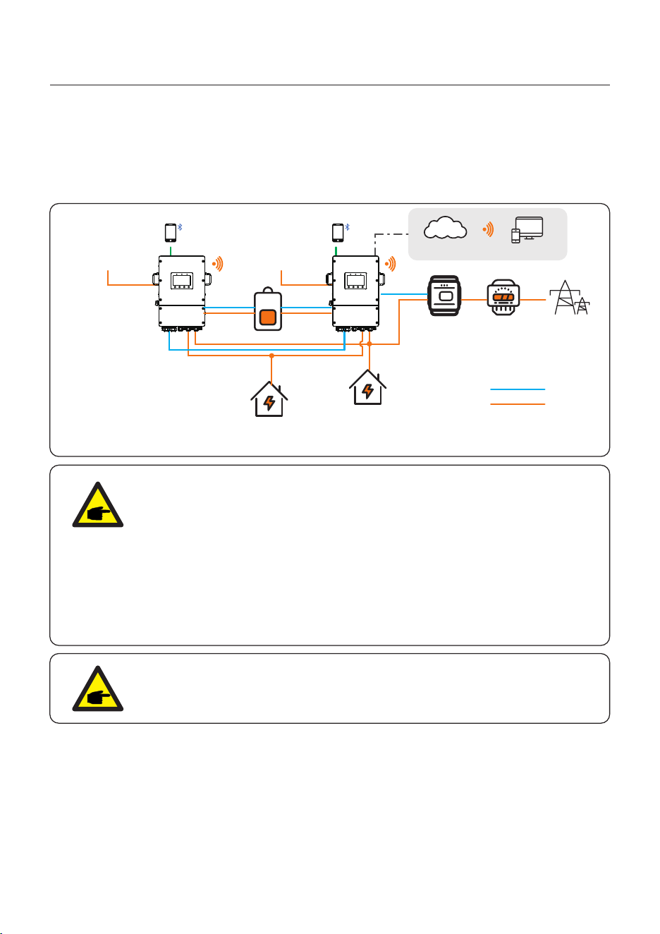
User can add inverters and batteries to increase capacity. The system supports up to 6
inverters in parallel. Inverter Share a battery system.
1.6.2 Parallel System
NOTE:
In parallel-system scenarios, maximum support 6 parallel connections.
Parallel connection of different models is not supported.(Like 12K and 15K
can't be connected in parallel).
The AC-Backup port can be connected in parallel, and the single-phase
output power is 1 / 2 of the total AC power.
In parallel-system scenarios, connecting DG via ATS is recommended;
In the parallel system, each inverter is recommended to plug in the
datalogger, otherwise, the remote upgrade cannot be performed.
The parallel cable between the two inverters should not exceed 5m.
NOTE:
Single inverter noise is less than 65 dB (A), When using multiple inverters
to combine, pay attention to noise protection.
Figure 1.4 Parallel System
SolisCloud
APP Web
Phone
Master
PV Module
CT/Smart Meter Power Meter
Grid
Battery
Grid Load
Backup Load
Phone
Slave
PV Module
Power Line
Signal Line
User Manual
1. Introduction
06
User Manual
1. Introduction
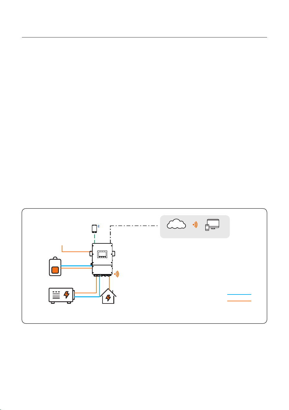
The access of Diesel Generator is in the off-grid scenario.
The system stores PV energy in batteries during daytime, provided that there is energy
surplus and supplies power to loads when the PV energy is insufficient or there is no PV
energy at night.
When the battery power drops to a certain value, and a power outage occurs in the grid,
the system will start the generator to power the load and charge the battery.
Generator’s work logic is as follows:
(i)when the grid is not available and the battery is discharged to GEN_Start_SOC, the
generator starts to power the load and charges the battery to GEN_Exit_SOC, then the
generator stops.
(ii)If the load power>the generator rated power in (i), the battery will be discharged to
power the load until Overdischarge_SOC, then generator may shutdown due to
overload and the load will be powered off.
(iii)If the generator fail to start in (i), the battery will be discharge to Overdischarge_SOC,
then the load power off.
(iv)If the system goes into the end of (iii), the battery will not discharge before it is
charged to Overdischarge_SOC+ Overdischarge_Hysteresis_SOC (set by user).
1.6.3 System with generator
Figure 1.5 Typical off-grid scenario diagram (Generator on Gen port)
SolisCloud
APP Web
Backup Load
Generator
Battery
PV Module
Phone
Power Line
Signal Line
Hybrid Inverter
07
User Manual
1. Introduction
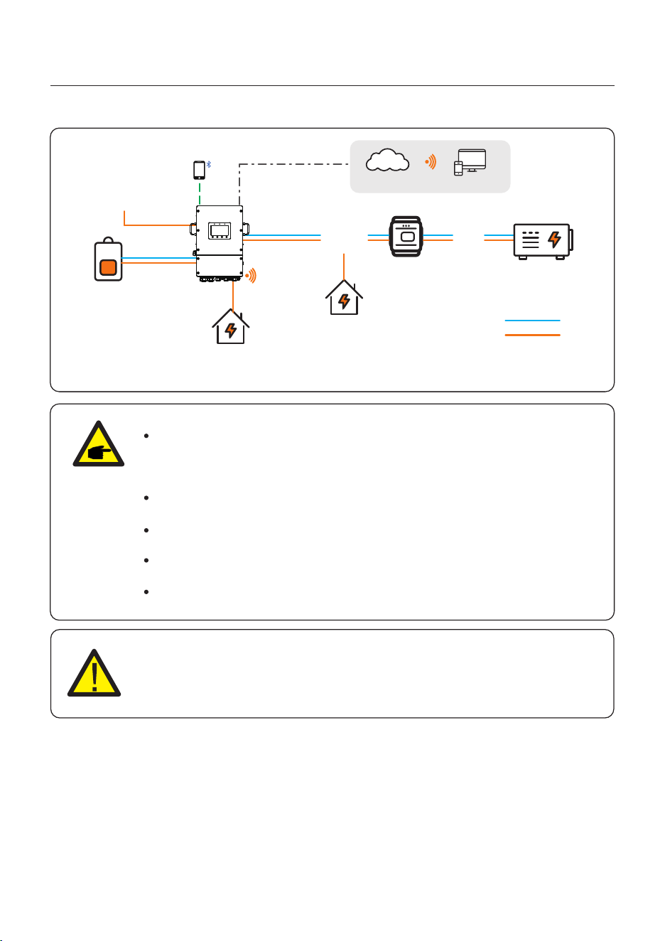
Figure 1.6 Typical off-grid scenario diagram (Generator on ATS)
SolisCloud
APP Web
Backup Load
Grid Load
CT/Smart Meter ATS Generator
Phone
Battery
PV Module
Hybrid Inverter
Power Line
Signal Line
NOTE:
In single system, a diesel generator can be connected via both AC-Gen port
and ATS. If via AC-Gen port, it will only supply power to the backup load ;
if it is necessary to supply power to the grid side, it is recommended that the
generator be connected through ATS.
In parallel-system scenarios, connecting a diesel generator via ATS is
recommended.
When the system is connected to the generator, it cannot be connected to a
grid-tied inverter, because of a risk of damaging the generator.
It is recommended that the generator power be greater than the backup load
power.
If the generator is connected through an ATS on the grid side, then CT or
smart meter is required.
CAUTION:
When the generator is connected, it is essential to correctly select the
generator position on the APP, otherwise it may cause system failure or
damage to the generator.
08
User Manual
1. Introduction
Generally, the access of grid-tied inverter is for the retrofit of a existing PV plant.
The S6 hybrid inverter support access of both Solis grid-tied inverter and third-party
grid-tied inverter.
1.6.4 System with grid-tied inverter
1.6.4.1 Access of third-party grid-tied inverter
Figure 1.7 Typical off-grid AC-coupled diagram(off-grid)
Backup Load
Battery
PV Module
Existing PV Plant
SolisCloud
APP Web
Phone
Hybrid Inverter
Power Line
Signal Line
Figure 1.8 Typical on-grid AC-coupled diagram(on-grid)
Battery
PV Module
Phone
Backup Load
Existing PV Plant
CT/Smart Meter Power Meter
Grid
Grid Load
SolisCloud
APP Web
Power Line
Signal Line
09
Third-party grid-tied inverter can be connected via AC-Gen port.
With third-party grid-tied inverter connected to the system, it is recommended that:
Grid-tied inverter power< rated AC power of S6 inverter.
In on-grid scenario, when the third-party grid-tied inverter is connected, the system
cannot control the output power of the third-party grid-tied inverter, so Feed-in limitation
cannot be realized.
In off-grid scenario, the third-party grid-tied inverter must be configured with the correct
grid code and equipped with over-frequency load shedding and under-frequency load
rising functionalities. These features allow the system to dynamically adjust the frequency,
effectively controlling the output power of the grid-tied inverter.
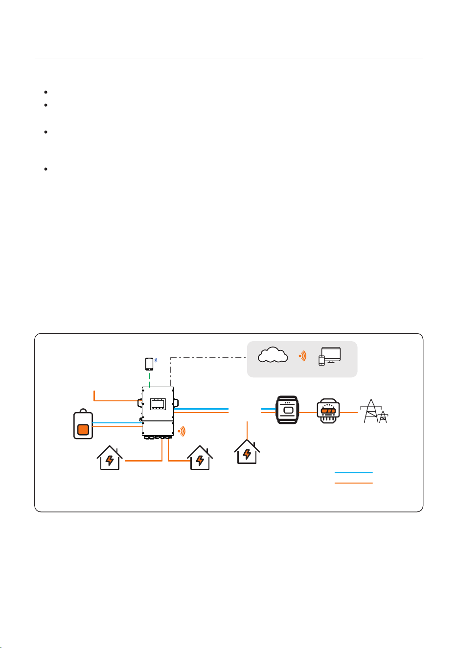
The Gen port has extended power, which can be used as Smart load output.
You can use the smartload function to connect critical loads to the backup port and
non-critical loads to the Gen port. This allows you to manage the power supply of
different loads when off-grid.
When the battery SOC/Volt reach the ON set value, the smart port will supply power to
the load. When the battery SOC/Volt drops to OFF SOC/Volt, it will cut off the power of
the load.
1.6.5 System with Smartload
Figure 1.9
Battery
PV Module
Phone
Backup Load
CT/Smart Meter Power Meter
Grid
Grid Load
SolisCloud
APP Web
Power Line
Signal Line
Smartload
User Manual
1. Introduction
10
2. Safety & Warning
User Manual
2.1 Safety
The following types of safety instructions and general information appear in this
document as described below:
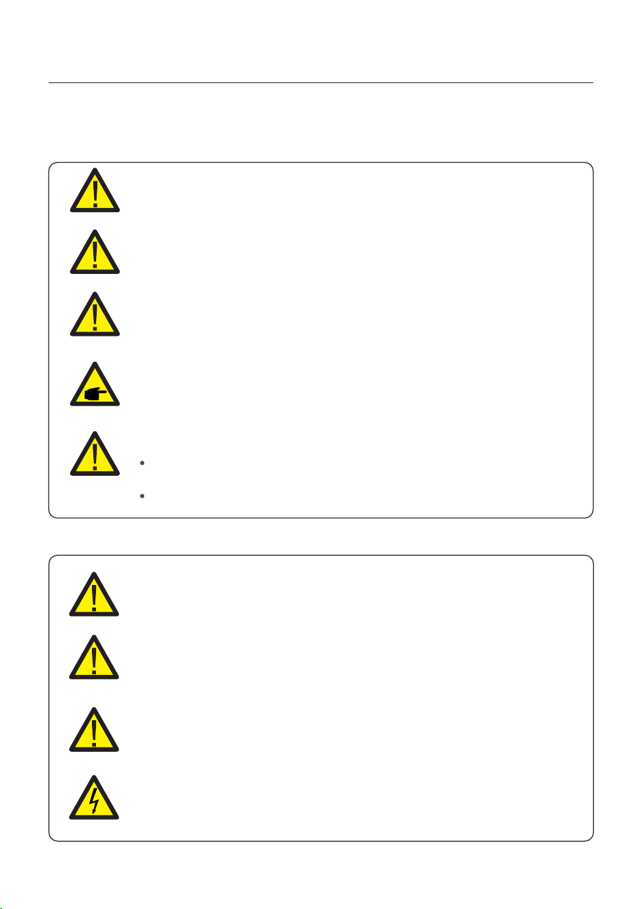
CAUTION
“Caution” indicates a hazardous situation which if not avoided, could result
in minor or moderate injury.
WARNING
“Warning” indicates a hazardous situation which if not avoided, could result
in death or serious injury.
DANGER
“Danger” indicates a hazardous situation which if not avoided, will result in
death or serious injury.
NOTE
“Note” provides tips that are valuable for the optimal operation of your
product.
2.2 General Safety Instructions
WARNING
Electrical installations must be done in accordance with local and national
electrical safety standards.
WARNING
Do not connect PV array positive (+) or negative (-) to ground, doing so could
cause serious damage to the inverter.
WARNING
Only devices in compliance with SELV (EN 69050) may be connected to the
RS485 and USB interfaces.
WARNING
Do not touch any internal parts until 5 minutes after disconnection
from the utility grid, PV array, and battery.
WARNING: Risk of fire
Despite careful construction, electrical devices can cause fires.
Do not install the inverter in an area containing flammable materials
or gases.
Do not install the inverter in a potentially explosive atmosphere.
11
2. Safety & Warning
User Manual
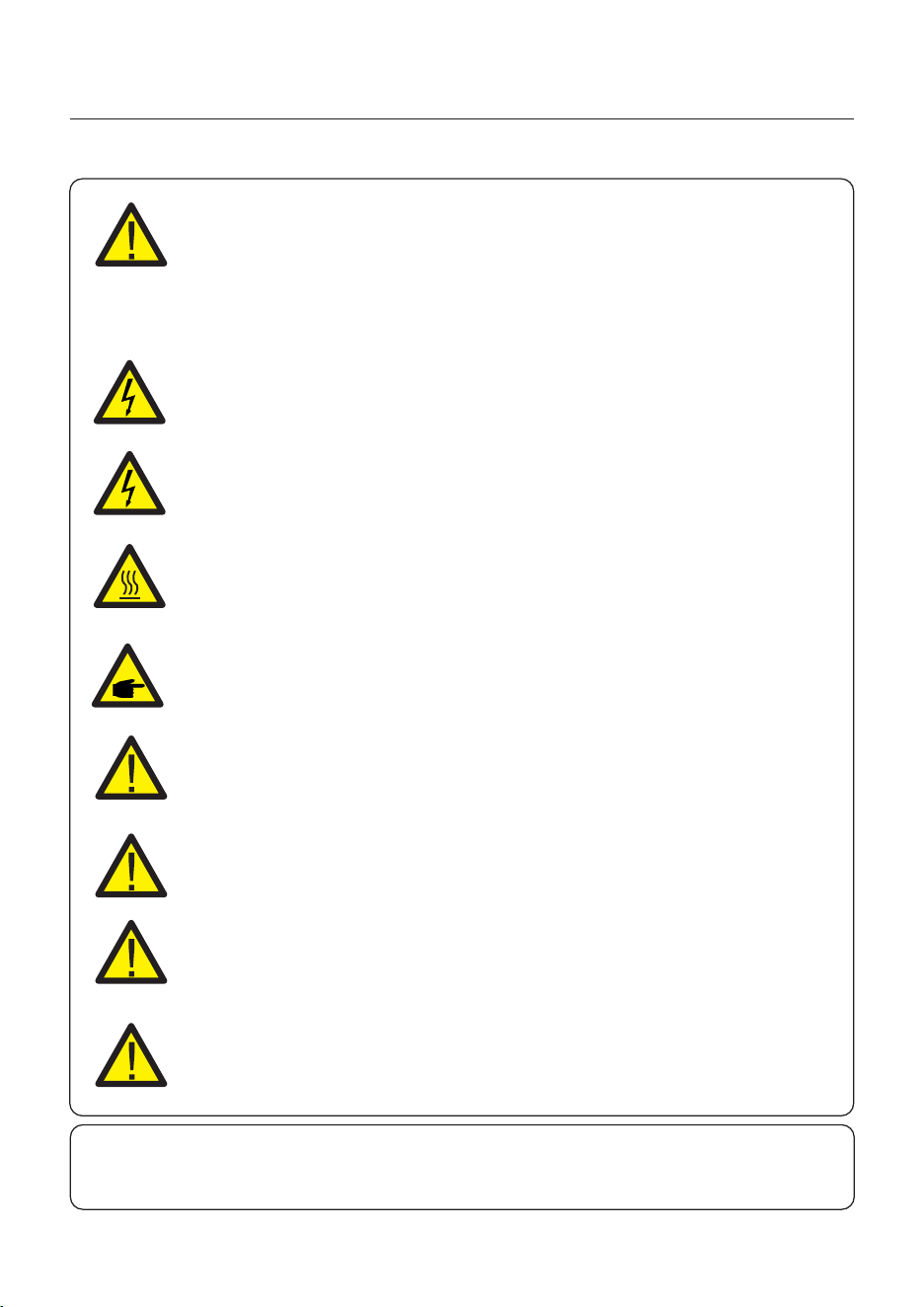
CAUTION
The PV conductors are energized with high voltage DC when the PV
modules are exposed to sunlight.
CAUTION
The surface temperature of the inverter can reach up to 75℃ .
To avoid risk of burns, do not touch the surface of the inverter while it is
operating. The inverter must be installed out of direct sunlight exposure.
WARNING
To reduce the risk of fire, over-current protective devices (OCPD) are
required for all circuits connected to the inverter.
The DC OCPD shall be installed per local requirements. All photovoltaic
source and output circuit conductors shall have isolators that comply with
the NEC Article 690, Part II.
All Solis single phase inverters feature an integrated DC disconnect switch.
CAUTION
Risk of electric shock, do not remove the cover. There are no serviceable
parts inside, refer servicing to qualified and accredited service technicians.
NOTE
PV modules used with inverter must have an I EC 61730 Class A rating.
WARNING
Operations must be accomplished by a licensed electrician or a
person authorized by Solis.
WARNING
Installer must wear personal protective equipment during the
entire installation process in case of electrical hazards.
WARNING
The AC Backup Port of the inverter cannot be connected to the grid.
WARNING
Please refer to the product manual of the battery before installation
and configuration to the inverter.
Systems using this product shall be designed and built in
accordance with the NEC & local electrical codes & standards.
12

2. Safety & Warning
User Manual
2.3 Notice for Use
The inverter has been constructed according to the applicable safety and technical
guidelines, use the inverter in installations that meet the following specifications only:
1. Permanent installation is required.
2. The electrical installation must be compliant with all local and national regulations &
standards.
3. The inverter must be installed according to the instructions stated in this manual.
4. The inverter must be installed according to the inverter technical specifications.
5. The inverter contains an internal NEB that meets the requirements of
NRS 097-2-1:2024 Section 5.4.
2.4 Notice for Disposal
This product shall not be disposed as household waste.
It must be segregated and brought to an appropriate disposal facility
to ensure proper recycling.
This is to be done in order to avoid negative impacts on the environment
and human health.
Local waste management rules shall be observed and respected.
13
User Manual
WARNING: Risk of fire
Despite careful construction, electrical devices can cause fires.
Do not install the inverter in areas containing highly flammable materials
or gases.
Do not install the inverter in potentially explosive atmospheres.
The mounting structure where the inverter is installed must be fireproof.
3. Installation
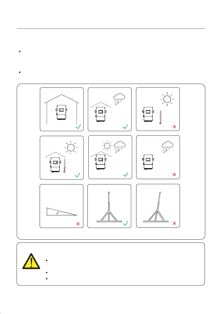
3.1 Select a Location to Install the Inverter
When selecting a location for the inverter, the following criteria should be considered:
Exposure to direct sunlight may cause output power derating due to overheating
It is recommended to avoid installing the inverter in direct sunlight. The ideal location is
one where the ambient temperature does not exceed 40°C.
It is also recommended to install the inverter somewhere the rain and snow will not land
directly on it. The ideal installation location is on a north-facing wall under an eave.
Figure 3.1 Recommended Installation locations
≥15°
Indoor
Direct Sun
Shade Cover
Shade Cover
Direct Rain
Rating
NEMA 4X
14
User Manual
3. Installation
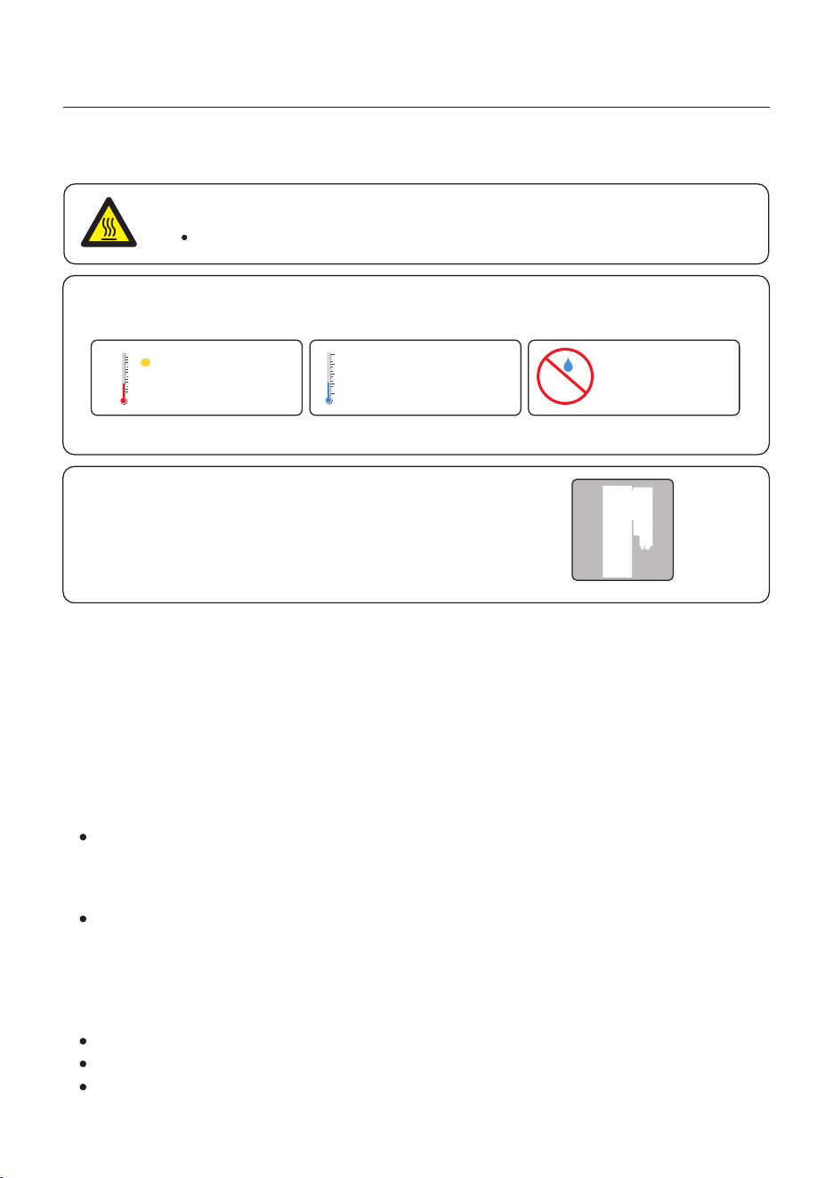
When selecting a location for the inverter, consider the following:
The temperature of the inverter heat-sink can reach 75℃.
The ambient temperature and relative humidity of the installation environment should
meet the following requirements:
The fan of the inverter is the left inlet wind, the right outlet wind .
To avoid overheating, always make sure the flow of air around the inverter is not blocked.
A minimum clearance of 300mm should be kept between objects;
A minimum clearance of 700mm should be kept between inverters;
In order to have enough space for installation and maintenance, we recommend that the front
distance is ≥500mm,the bottom of the inverter should be
at least 500mm above of the ground or floor, which can be adjusted according to the actual situation.
CAUTION: Hot Surface
Made of non-inflammable materials
Max. load bearing capacity ≥ 4 times of inverter weight
3.1.2 Consult technical data
Consult the technical specifications sections at the end of this manual for additional environmental
condition requirements (temperature range, altitude, etc.)
This model of Solis inverter must be mounted vertically (90 degrees or backwards less than or
equal to 15 degrees from 90 degrees straight up).
3.1.3 Angle of installation
3.1.1 Clearances
Load bearing surface:
Figure 3.2 Installation environment conditions
Max: +60℃ Max: -40℃ Max.RH : 95%
(non-condensing)
15
3.1.4 Avoiding direct sunlight
Installation of the inverter in a location exposed to direct sunlight should to be avoided.
Direct exposure to sunlight could cause:
Power output limitation (with a resulting decreased energy production by the system).
Premature wear of the electrical/electromechanical components.
Premature wear of the mechanical components (gaskets) and user interface.
3.1.6 Flammable substances
Do not install near flammable substances. Maintain a minimum distance of three meters
(10 feet) from such substances.
3.1.7 Living area
Do not install in a living area where the prolonged presence of people or animals is expected.
Depending on where the inverter is installed (for example: the type of surface around the
inverter, the general properties of the room, etc.) and the quality of the electricity supply, the
sound level from the inverter can be quite high.
3.2 Product Handling
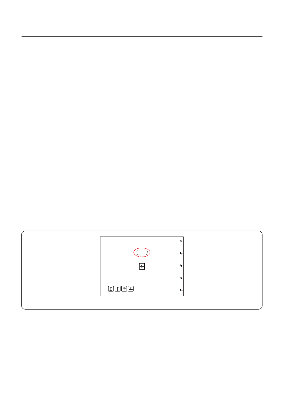
Figure 3.3
3.1.5 Air circulation
Do not install in small, closed rooms where air cannot freely circulate.
To prevent overheating, always ensure that the air flow around the inverter is not blocked.
Please review the instruction below for handling the inverter:
1. The red circles below denote cutouts on the product package - one per side.
Push in the cutouts to form handles for moving the inverter (see Figure 3.3).
2. Two people are required to remove the inverter from the shipping box. Use the handles
integrated into the heat sink to remove the inverter from the carton.
3. When setting the inverter down, do it slowly and gently. This ensures that the internal
components and the outer chassis do not take any damage.
User Manual
3. Installation
16
Visibility of the LED indicator lights should be considered.
Adequate ventilation around the inverter must be provided.
NOTE
Nothing should be stored on the top of or placed against the inverter.
The inverter must be mounted vertically with a maximum incline of +/- 5 degree.
Exceeding this may cause the output power to derate.
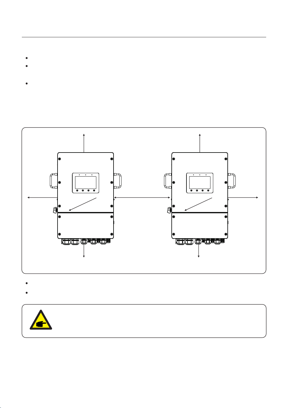
Figure 3.4 Inverter Mounting Clearances
Mount the inverter on a wall or structure capable of bearing the weight of the machine.
3.3 Mounting the Inverter
User Manual
3. Installation
The fan of the inverter is the left inlet wind, the right outlet wind .To avoid overheating,
always make sure the flow of air around the inverter is not blocked. A minimum clearance
of 700mm should be kept between inverters and 300mm be kept from objects;
In order to have enough space for installation and maintenance, we recommend that the
front distance is ≥500mm, which can be adjusted according to the actual situation.
≥300mm ≥700mm
≥300mm
≥
50
0mm
17
≥300mm
≥300mm
≥5
00
m
m
≥500mm ≥500mm
User Manual
3. Installation
18
The inverter shall be mounted vertically.
The steps to mount the inverter are listed as below:
1. Select the mounting height of the bracket and mark the mounting holes.
For brick walls, the position of the holes should be suitable for the expansion bolts.
WARNING:
The inverter must be mounted vertically.
Once a suitable location has be found according to 3.1 using figure 3.5 mount the wall
bracket to the wall.
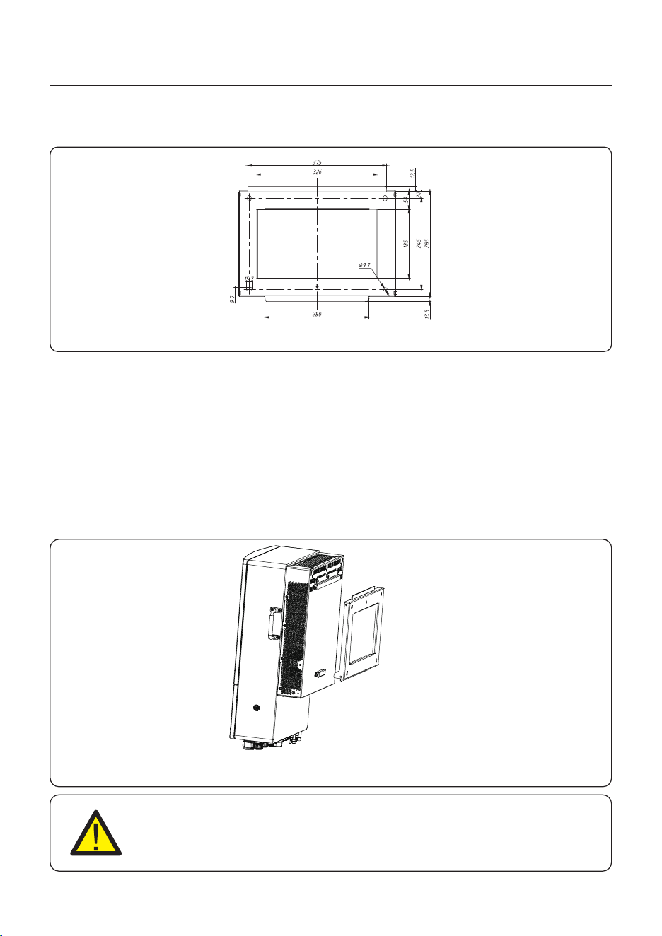
Dimensions of mounting bracket:
unit:mm
Figure 3.6 Wall mount bracket
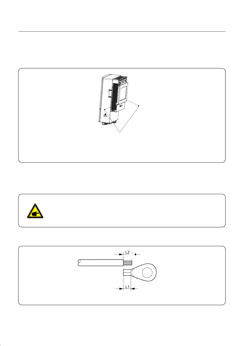
2. Lift up the inverter (be careful to avoid body strain), and align the back bracket on the
inverter with the convex section of the mounting bracket. Hang the inverter on the
mounting bracket and make sure the inverter is secure (see Figure 3.6)
Figure 3.5 Inverter wall mounting
Connection Points
From the PV array to the DC+
and DC- terminals in the inverter
From the battery (+) and (-) terminals to
the inverter BAT+ and BAT- terminals
From the OCPD in the main service panel to
the AC-GRID L1, L2, L3 terminals
From the backup loads subpanel OCPD to
the inverter AC-BACKUP L1, L2, L3 terminals
From the main service panel ground bar to
the ground bar inside the inverter wire box
PV DC connection
to the inverter
Battery DC connection
to the inverter
Inverter AC connection
to the main service panel
Inverter AC connection
to the backup subpanel
PV Cables
Battery Cables
AC Grid Cables
AC Backup Cables
Ground Cables
From meter to terminal HM.
For more details, refer to figure
Installing the energy meter
From battery to terminal BMS.
For more details, refer to figure
Installing the battery
USB COM port at the bottom of the inverter
(For more details, please refer to the
Solis data logger product manual)
Communication
between inverter & CT
Communication between
the inverter & the battery
Monitoring of the system
on SolisCloud
CT cable
Battery
communication cable
Data Logger
(Optional)
Grounding conductors
for the system
Purpose
NOTE
Conductor dimensions and OCPD sizing to be determined in accordance
with the national electrical code (NEC) and local standards.
3.4 Inverter Wiring Overview
User Manual
3. Installation
19
3.5 Ground Cable Installation
1. It is recommended to use copper wire for the chassis ground. Either solid conductor or
stranded wire is acceptable. Refer to local code standard for wire sizing.
2. Attach OT terminal: M5.
To connect the grounding terminal on the heat sink, please follow the steps below:
A
B
IMPORTANT
3. Strip the ground cable insulation to a suitable length.
4. Crimp a ring connector onto the cable and then connect it to the chassis ground terminal.
Figure 3.8 External Grounding Conductor Terminal
For multiple inverters in parallel , all inverters should be connected to the
same ground point to eliminate the possibility of a voltage potential existing
between inverter grounds.
User Manual
3. Installation
An external ground connection is provided at the both sides of inverter.
Prepare OT terminals: M5. Use proper tooling to crimp the lug to the terminal.
Connect the OT terminal with ground cable to the right side of inverter. The torque is 3.3N.m.
20
Figure 3.7 Connect the external grounding conductor
M5 Screw removed
Torque: 3.3N.m
Earth wire
Earth wire
User Manual
3. Installation
21
3.6 PV Cable Installation
Negative terminal
Positive terminal
Before connecting inverter, please make sure the PV array open circuit
voltage is within the limit of the inverter.
Please use approved DC cable for PV system.
4.0~6.0
4.0(12AWG)
(12~10AWG)
Cable type
Cross section(mm²)
Range
Industry generic P V cable
Recommended value
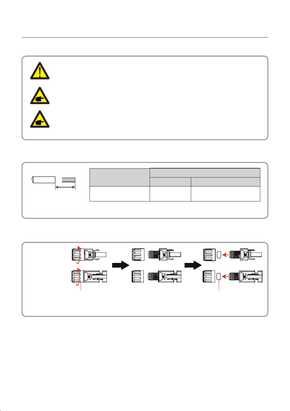
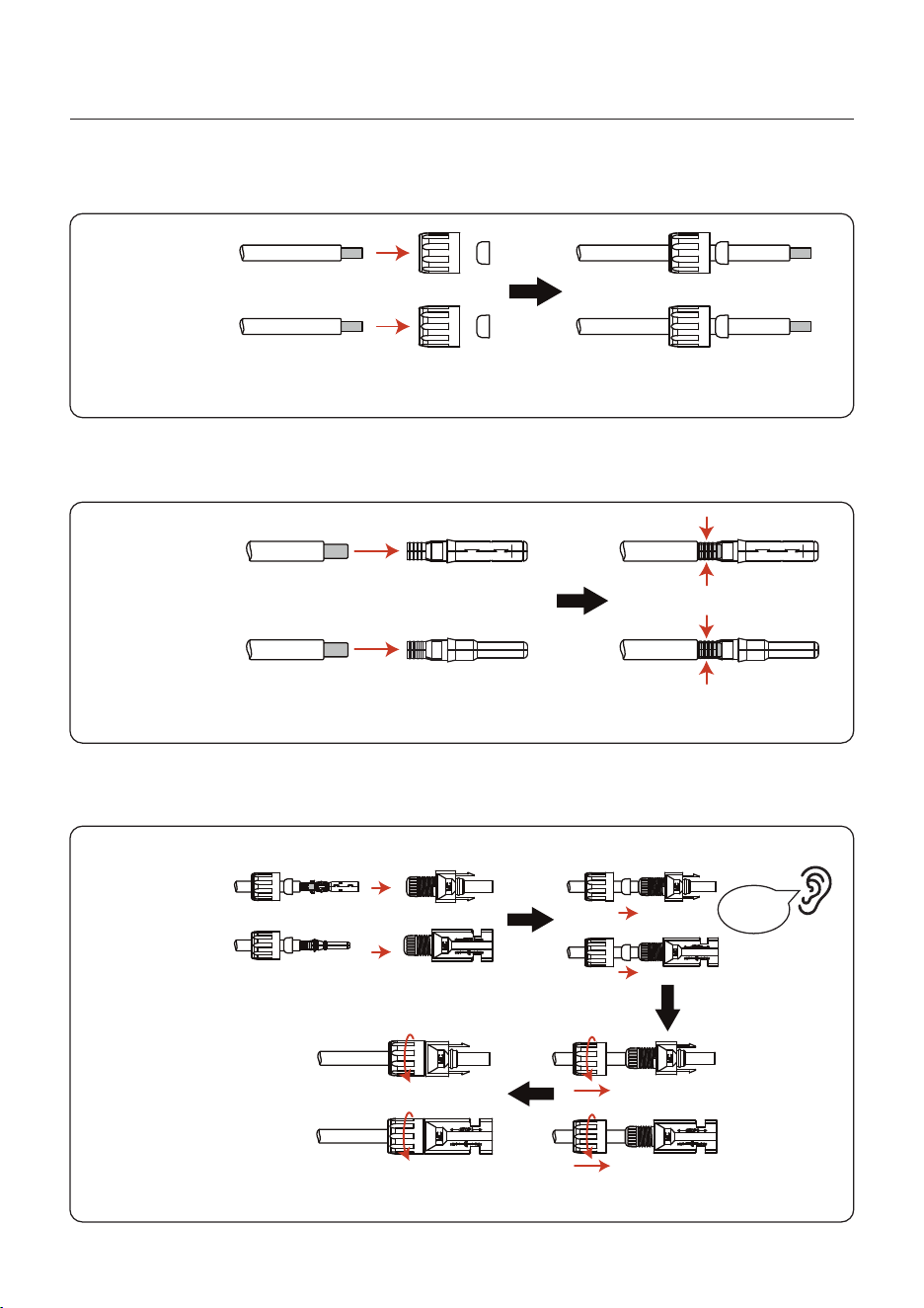
1. Select a suitable DC cable and strip the wires out by 7±0.5mm. Please refer to the table
below for specific specifications.
7±0.5mm
2. Take the DC terminal out of the accessory bag, turn the screw cap to disassemble it,
and take out the waterproof rubber ring.
Nut Waterproof collar
Figure 3.9
Figure 3.10
Before connection, please make sure the polarity of the output voltage of
PV array matches the“DC+”and“DC-”symbols.
User Manual
3. Installation
22
Negative terminal
Positive terminal
3. Pass the stripped DC cable through the nut and waterproof rubber ring.
4. Connect the wire part of the DC cable to the metal DC terminal and crimp it with a special
DC terminal crimping tool.
Negative terminal
Positive terminal
Squeeze
5. Insert the crimped DC cable into the DC terminal firmly, then insert the waterproof rubber
ring into the DC terminal and tighten the nut.
Tighten
After you hear a "click", pull gently to check for a firm engagement.
Click
Negative terminal
Positive terminal
Figure 3.11
Figure 3.12
Figure 3.13
User Manual
3. Installation
23
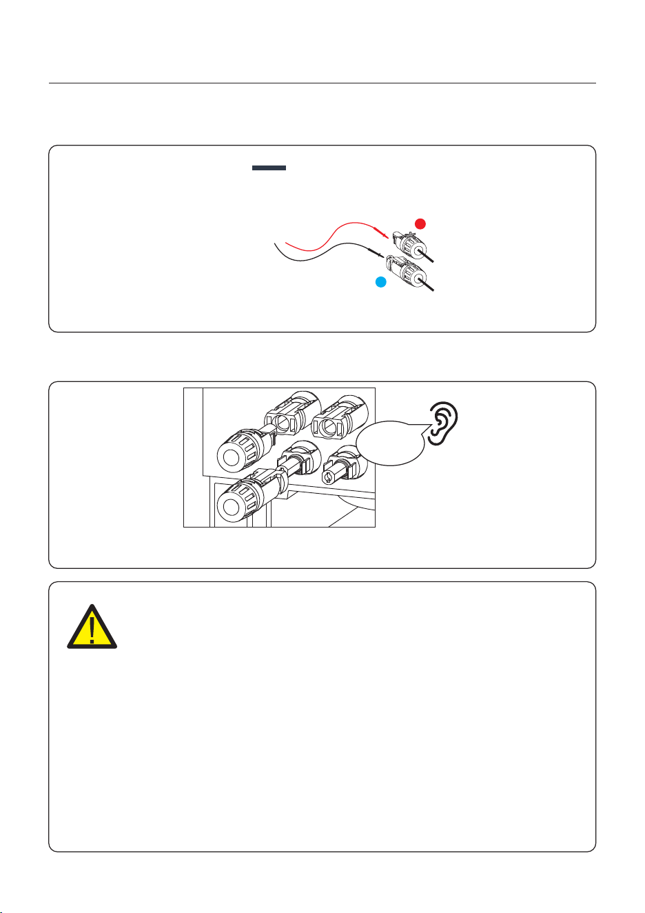
6. Measure PV voltage of DC input with multimeter, verify DC input cable polarity.
7. Connect the wired DC terminal to the inverter as shown in the figure, and a slight
"click" is heard to prove the connection is correct.
+
-
CAUTION:
If DC inputs are accidently reversely connected or inverter is faulty or not
working properly, it is NOT allowed to turn off the DC switch. Otherwise it
may cause DC arc and damage the inverter or even lead to a fire disaster.
The correct actions are:
*Use a clip-on ammeter to measure the DC string current.
*If it is above 0.5A, please wait for the solar irradiance reduces until the
current decreases to below 0.5A.
*Only after the current is below 0.5A, you are allowed to turn off the DC
switches and disconnect the PV strings.
* In order to completely eliminate the possibility of failure, please disconnect
the PV strings after turning off the DC switch to aviod secondary failures due
to continuous PV energy on the next day.
Please note that any damages due to wrong operations are not covered in
the device warranty.
Figure 3.14
Figure 3.15
Click
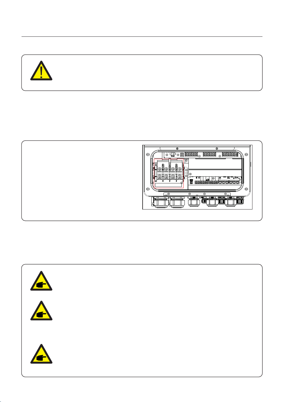
3.7 Battery Cable Installation
1. The battery (+) and (-) cables shall only be connected to the inverter BAT terminals.
2. Run the cables into the wire box. Strip 13mm off the ends of each cable.
3. Crimp the R-type connectors onto the cables. Do not over crimp the connectors.
4. Remove the terminal bolts and then insert them through the connector holes.
5. Put each bolt back into the proper place, be sure to not reverse the polarity.
6. Tighten the bolts with a torque wrench screwdriver following the torque specs.
Figure 3.16 Battery cable connection
DANGER
Before installing the battery cables, be sure that the battery is turned off.
Use a multimeter to verify that the battery voltage is 0Vdc before proceeding.
Consult the battery product manual for instructions on how to turn it off.
NOTE
Before connecting the battery, please carefully read the product manual of
the battery and perform the installation exactly as the battery manufacturer
specifies in the manual
NOTE
The battery fuse in the inverter wire box is replaceable.
The replacement can only be done by a technician authorized by Solis.
NOTE
Please use the battery that has been matched by Solis.
Please see the battery matching list on the Solis official website.
If the battery is not in the list, our company will not carry out after-sales
maintenance.
BAT+ BAT-
24
User Manual
3. Installation
Terminal:
M8 screws*4
Recommended cable diameter:
2AWG*4(33.62mm²*4)
The BAT+ terminal provides 2 inputs, each with a maximum of 200A.
It is recommended that each cable ≤150A.
The BAT- terminal provides 2 inputs, each with a maximum of 200A.
It is recommended that each cable ≤150A.
(max 290A charge/discharge current of the inverter).
User Manual
3. Installation
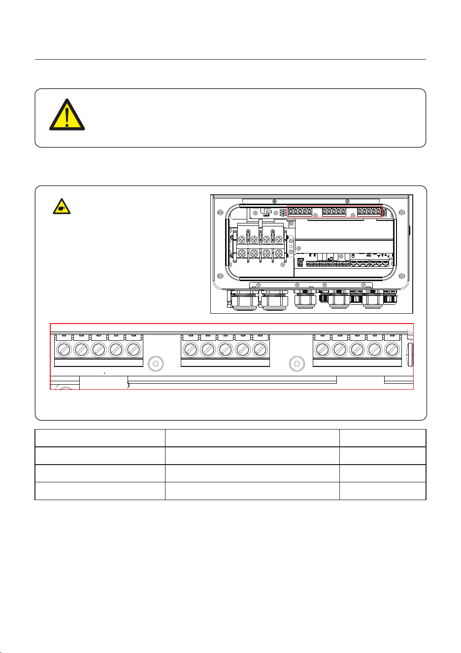
There are three sets of AC output terminals and the installation steps for both are the same.
The maximum temperature for connecting AC and battery terminals is 85°C.
3.8 AC Wiring
Figure 3.17 AC output terminals
DANGER
Before installing the AC cables, be sure that the OCPDs (breakers) are
turned off.
Use a multimeter to verify that the AC voltages are 0Vac before proceeding.
1. Bring the AC cables for the backup loads panel (backup) and the main service
panel (grid) into the inverter wire box. The backup loads panel should not be
electrically connected to the main service panel.
2. Strip 13mm from the ends of each cable. Crimp the R-type connectors onto the ends.
3. Remove the terminal bolts, insert them into the connectors, then use a torque wrench
to tighten the bolts down.
4. Please refer to the terminal labels to connect the AC wires to the correct terminals.
Model
Wire Size
Torque
Cable
6 AWG
18N.m
10 mm2
AC Gen/AC Backup/AC Grid
25
10 AWG
18N.m
4 mm2
GEN
VW
U
N PE VW
U
N PE VW
U
N PE
Backup Grid
Earth Bar
NOTE:
The sequence of phase lines
W(L3), V(L2), U(L1).
3.9 CT Connection
User Manual
3. Installation
CAUTION:
Make sure the AC cable is totally isolated from AC power before
connecting the or CT.
26
The CT provided in the product box is compulsory for hybrid system installation. It can be used
to detect the grid current direction and provide the system operating condition to hybrid inverter.
CT Model: ESCT-TA16-100A/50mA
CT Cable: Size – 2.3mm2, Length - 1m
Please install the CT on the hot line at the system grid connection point and the arrow on the
CT needs to point to the grid direction.
Lead the CT wires through the COM3 port at the bottom of the inverter and connect the CT
wires to the 16pin communication terminal block.
3.9.1 CT Installation
CT Wire
White
Pin 1 (From Left to Right)
Pin 2 (From Left to Right)
Pin 3 (From Left to Right)
Pin 4 (From Left to Right)
Pin 5 (From Left to Right)
Pin 6 (From Left to Right)
Black
Black
Black
16 PIN Communication Terminal Block
White
White
U(L1)
V(L2)
W(L3)
3.10 Inverter Communication
User Manual
3. Installation
3.10.1 Communication Ports
Port
COM1
COM2
COM3
COM4
DescriptionPort Type
USB
6 hole watertight cable gland
4 hole watertight cable gland
Used for Solis data logger connection
Used for 16 PIN terminal block connection
inside wiring box
Used for RJ45 connection inside wiring box
Wiring steps for COM2-COM5:
Step 1. Loose the cable gland and remove the watertight caps inside the cable gland based
on the number of the cables and keep the unused holes with watertight cap.
Step 2. Lead the cable into the holes in the cable gland.
(COM2-COM3 Hole Diameter: 6mm, COM4-COM5 Hole Diameter: 2mm)
Step 3. Connect the cable to the corresponding terminals inside the wiring box.
Step 4. Reassemble the cable gland and ensure there is no bending or stretching of the cables
inside the wiring box.
NOTE:
The 4-hole fastening rings inside the cable
gland for COM2 and COM3 are with openings
on the side.
Please separate the gap with hand and squeeze
the cables into the holes from the side openings.
27
COM5
4 hole watertight cable gland
Used for RJ45 connection inside wiring box
6 hole watertight cable gland
Used for 16 PIN terminal block connection
inside wiring box
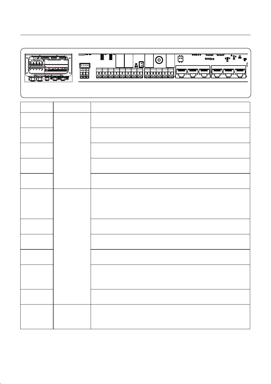
3.10.2 Communication Terminals
User Manual
3. Installation
Figure 3.18 Communication terminals
28
Terminal
BMS
Meter
RS485
DRM
Parallel B/
Parallel A
HS-VCC/
HS-A/
HG-VCC/
HG-A
GND-DI/
GEN-DI
GEN-S
GEN-V
L1CT/
L2CT/
L3CT
ATS
DIP Switch
(2-1)
DescriptionType
Used for RS485 communication between inverter and the
smart meter.
Used for CAN communication between inverter and Lithium
battery BMS.
Third-party external devices.
(Optional) To realize Demand Response or Logic Interface
function, this function may be required in UK and Australia.
(Optional) Parallel operation communication port.
Reserve.
Connect to GEN.
Connect to Cts.
In parallel:
Turn the DIP switch of the first and last inverter to: ON, and
the other machines to OFF.
RJ45
Terminal
Block
-
Reserve(Heat pump).
L
N
ATS
HS-VCC
P-A P-B DRM RS485 BMS METER
1 2
ON
+
HS-A
HG-VCC
HG-A
L1CT
-+
L2CT
-+
L3CT
-
B
GEN-V
A B
GEN-S
A
GND-DI
GEN-DI+
Reserve(GEN signal).
Reserve.

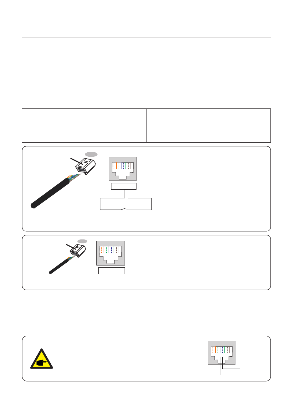
3.10.3 BMS Terminal Connection
User Manual
3. Installation
CAN communication is supported between inverter and compatible battery models.
Please lead the CAN cable through the COM1 or COM2 port of the inverter and connect to
the BMS terminal with RJ45 connector.
NOTE:
Before connecting CAN cable with the battery, please check whether the
communication pin sequence of the inverter and the battery match;
If it does not match, you need to cut off the RJ45 connector at one end of the
CAN cable and adjust the pin sequence according to the pin definitions of
both inverter and battery.
Pin definition of the inverter BMS Port is following
EIA/TIA 568B.
CAN-H on Pin 4: Blue
CAN-L on Pin 5: Blue/White
RJ45terminal
1 2 3 4 5 6 7 8
CAN-L
CAN-H
CAN
3.10.3.1 With Lithium Battery
29
NOTE:
Before connecting RS485 cable with the battery, please check whether the
communication pin sequence of the inverter and the battery match;
If it does not match, you need to cut off the RJ45 connector at one end of the
RS485 cable and adjust the pin sequence according to the pin definitions of
both inverter and battery.
Pin definition of the inverter BMS Port is following
EIA/TIA 568B.
RS485A on Pin 6: Green
RS485B on Pin 3: Green/White
RJ45terminal
1 2 3 4 5 6 7 8
RS485A
RS485B
User Manual
3. Installation
3.10.4 Meter Terminal Connection
If a smart meter is preferred to be installed other than the provided CT, please contact Solis
sales rep to order the smart meter and corresponding meter CT.
Please lead the Meter RS485 cable through the COM1 or COM2 port of the inverter and
connect to the Meter terminal with RJ45 connector.
NOTE:
Pin definition of the Meter Terminal is following
EIA/TIA 568B.
RS485A on Pin 1:Orange/white
RS485B on Pin 2:Orange
RJ45terminal
1 2 3 4 5 6 7 8
RS485B
RS485A
METER
A
B
30
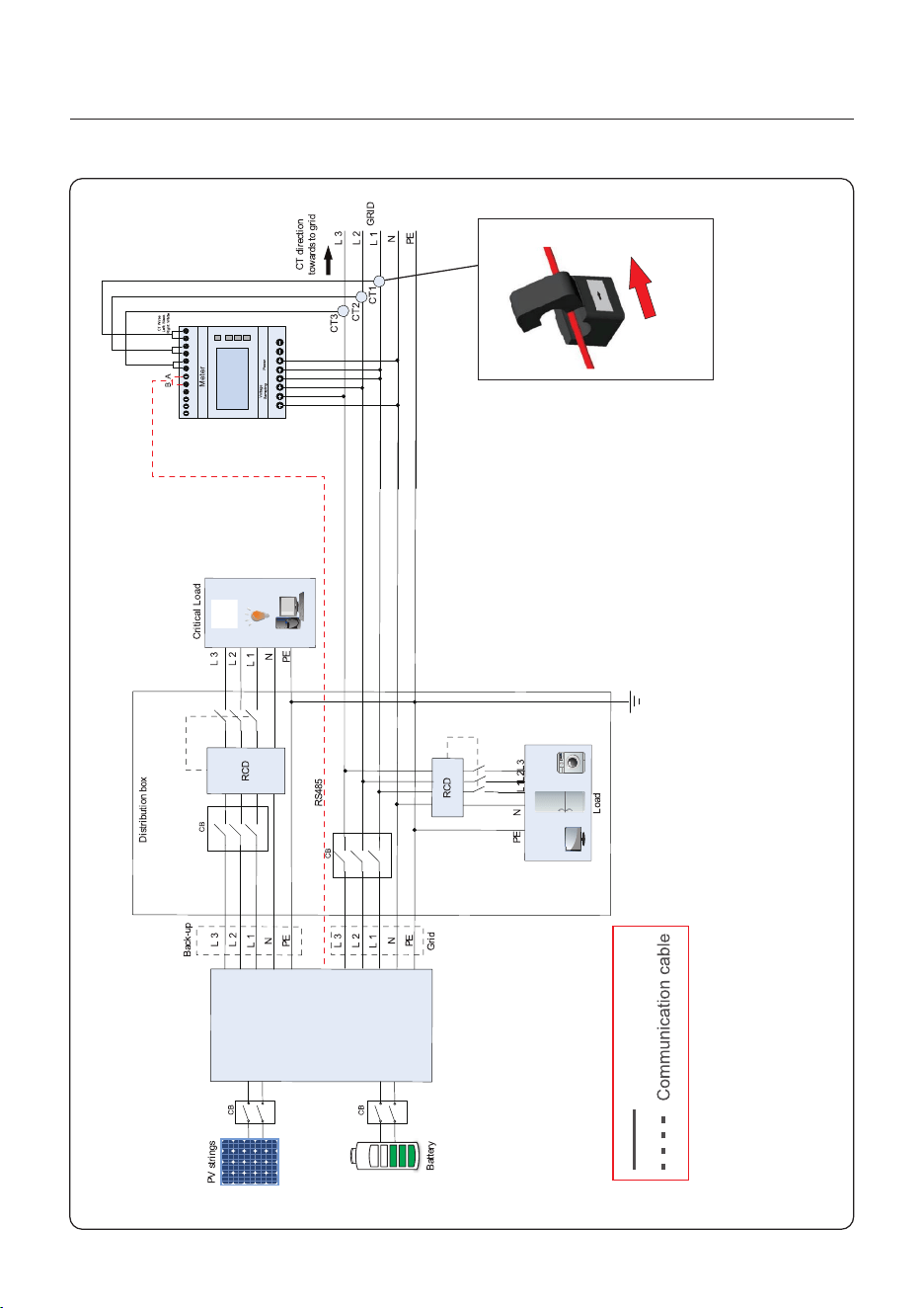
User Manual
3. Installation
Figure 3.19 Eastron SDM630MCT
S6-E H3P(8-15) K02-NV-YD-L
Power cable
Note:
If the CT is installed in the wrong direction,
the Hybrid Inverter can't work normally.
CT direction
towards to grid
Gr
id
s
id
e
K
L
9 10
111213141516171819 20
1 2 3 4 5 6 7 8
31
3.10.5.1 For Remote Shutdown Function
Solis inverters support remote shutdown function to remotely control the inverter to power on
and off through logic signals.
The DRM port is provided with an RJ45 terminal and its Pin5 and Pin6 can be used for remote
shutdown function.
Signal
Short Pin5 and Pin6 Inverter Generates
Inverter Shutdown in 5s
Open Pin5 and Pin6
Function
Correspondence between the cables
and the stitches of plug, Pin5 and Pin6
of RJ45 terminal is used for the logic
interface, other Pins are reserved.
Pin 1: Reserved; Pin 2: Reserved
Pin 3: Reserved; Pin 4: Reserved
Pin 5: Switch_input1; Pin 6: Switch_input2
Pin 7: Reserved; Pin 8: Reserved
1--8
Rj45 plug
RJ45terminal
1 2 3 4 5 6 7 8
1 2 3 4 5 6 7 8
DRM(logic interface)
Switch input1_ Switch input2_
Figure 3.20 Strip the insulation layer and connect to RJ45 plug
User Manual
3. Installation
3.10.5 DRM Port Connection (Optional)
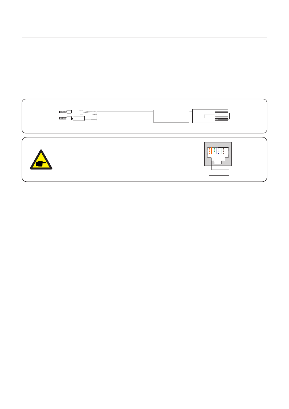
3.10.6 RS485 Port Connection (Optional)
Figure 3.21 Strip the insulation layer and connect to RJ45 plug
Correspondence between the
cables and the stitches of plug
Pin 1: white and orange ; Pin 2: orange
Pin 3: white and green; Pin 4: blue
Pin 5: white and blue; Pin 6: green
Pin 7: white and brown; Pin 8: brown
1--8
RJ45 plug
RJ45terminal
1 2 3 4 5 6 7 8
1 2 3 4 5 6 7 8
If a 3rd party external device or controller needs to communicate with the inverter, the RS485
port can be used. Communication protocol is supported by Solis inverters.
To acquire latest protocol document, please contact Solis local service team or Solis sales.
NOTE:
Pin definition of the RS485 Port is following
EIA/TIA 568B.
RS485A on Pin 5: Blue/White
RS485B on Pin 4: Blue
RJ45terminal
1 2 3 4 5 6 7 8
RS485A
RS485B
32
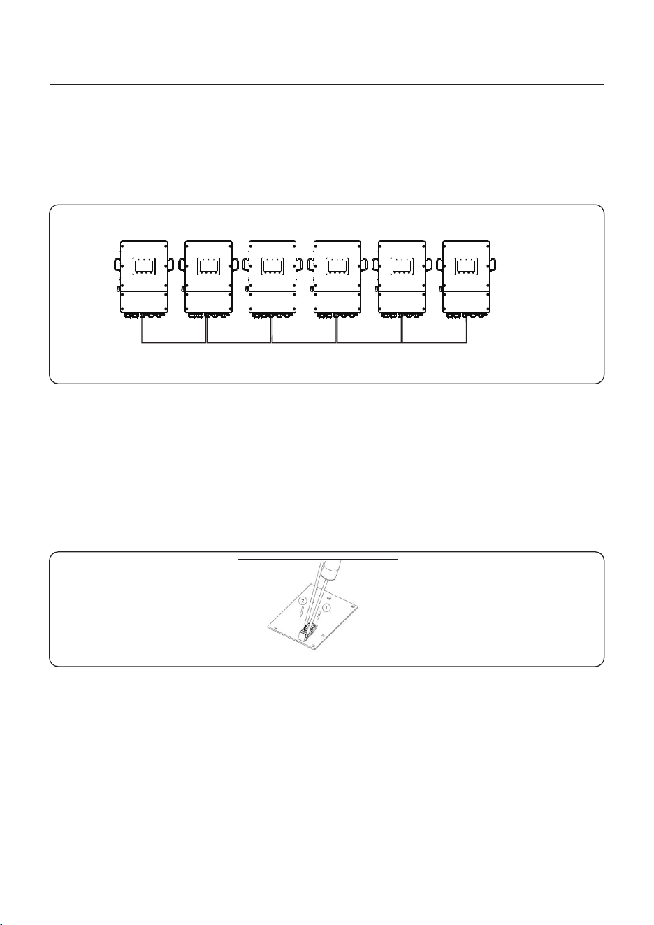
Up to 6 units of the inverter can be connected in parallel.
Please connect the paralleled inverters by using P-A and P-B terminals.
Standard CAT5(≤5m,between two inverters) with shielding layers internet cable can be used.
P_B P_A P_B P_A P_B P_A P_B P_A P_B P_A
3.10.7 Parallel Inverter Connection (Optional)
User Manual
3. Installation
Figure 3.22 Parallel Terminal Connection
Master Slave1 Slave2 Slave3 Slave4 Slave5
Terminal Block Connection Steps:
Step 1. Lead the wires through the hole in COM3 port (Hole Diameter: 2 mm)
Step 2. Strip the wires for 9mm length
Step 3. Use slot type screwdriver to press the block on the top
Step 4. Insert the exposed copper part of the cable into the terminal.
Step 5. Remove the screwdriver and the terminal will clamp down on the exposed copper part.
Step 6. Give the cable a gentle tug to ensure that it is firmly secured.
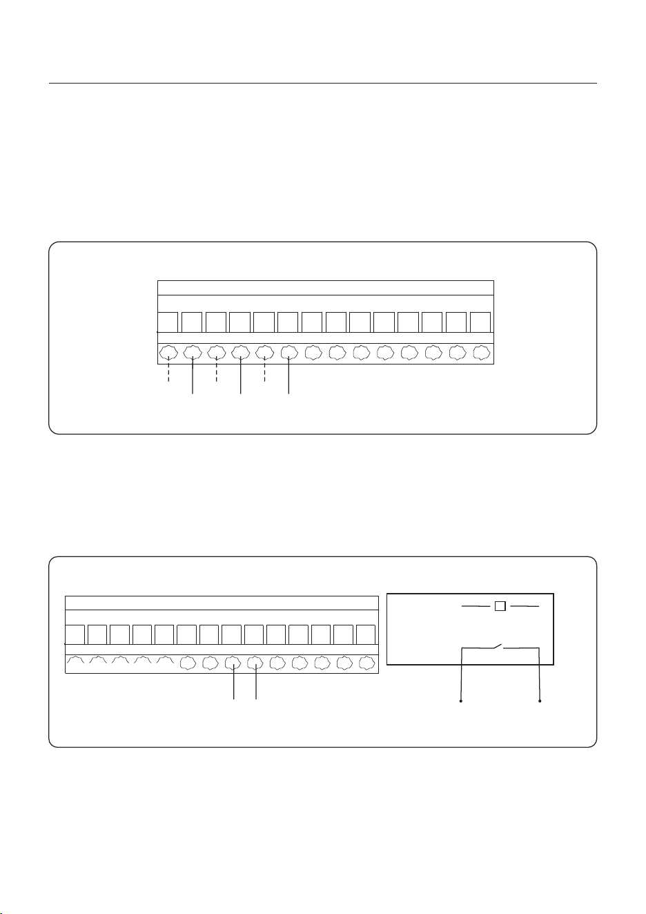
3.10.8 16-pin Communication Terminal Block
33
User Manual
3. Installation
The G-V terminal is a voltage-free dry contact signal for connecting with generator's NO relay
to start up the generator when necessary.
When generator operation is not needed, Pin8 and Pin9 is in open circuit.
When generator operation is needed, Pin8 and Pin9 is in short circuit.
16-Pin Communication
Terminal Block
3.10.8.2 G-V Terminal Connection
34
Figure 3.24
coil
open contact
G V
relay
1 2 3 4 5 6 7 8
G V
9
CT connection is necessary to realize the correct control logic of the hybrid inverter.
The CT provided in the inverter package has BLACK(S2) and WHITE(S1) wires. The BLACK
wire needs to connect to the Pin 2, Pin 4, Pin6 of the terminal block and the WHITE wire
needs to connect to the Pin 1, Pin3, Pin5 of the terminal block as in the following diagram.
16-Pin Communication
Terminal Block
3.10.8.1 HM Terminal Connection (CT Terminal Connection)
Figure 3.23
1 2
White
Black
3 4 5 6
The CT terminals are CT-L1(±)/ CT-L2(±)/ CT-L3(±) from left to right.
User Manual
3. Installation
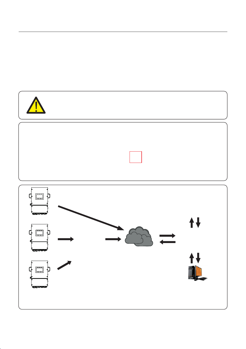
LAN monitoring
The inverter can be remotely monitored via WiFi, LAN or 4G.
The USB type COM port at the bottom of the inverter can connect to different kinds of Solis
data loggers to realize the remote monitoring on Soliscloud platform.
To install Solis data loggers, please refer to corresponding user manuals of Solis data loggers.
The Solis data loggers are optional and can be purchased separately.
Dust cover is provided the inverter package in case the port is not used.
WARNING:
The USB type COM port is only allowed to connect Solis data loggers.
It is forbidden to be used for other purposes.
4G monitoring
WiFi monitoring
Router
Internet
Web server
Figure 3.25 Wireless communication function
Soliscloud
APP
3.11 Inverter Remote Monitoring Connection
35
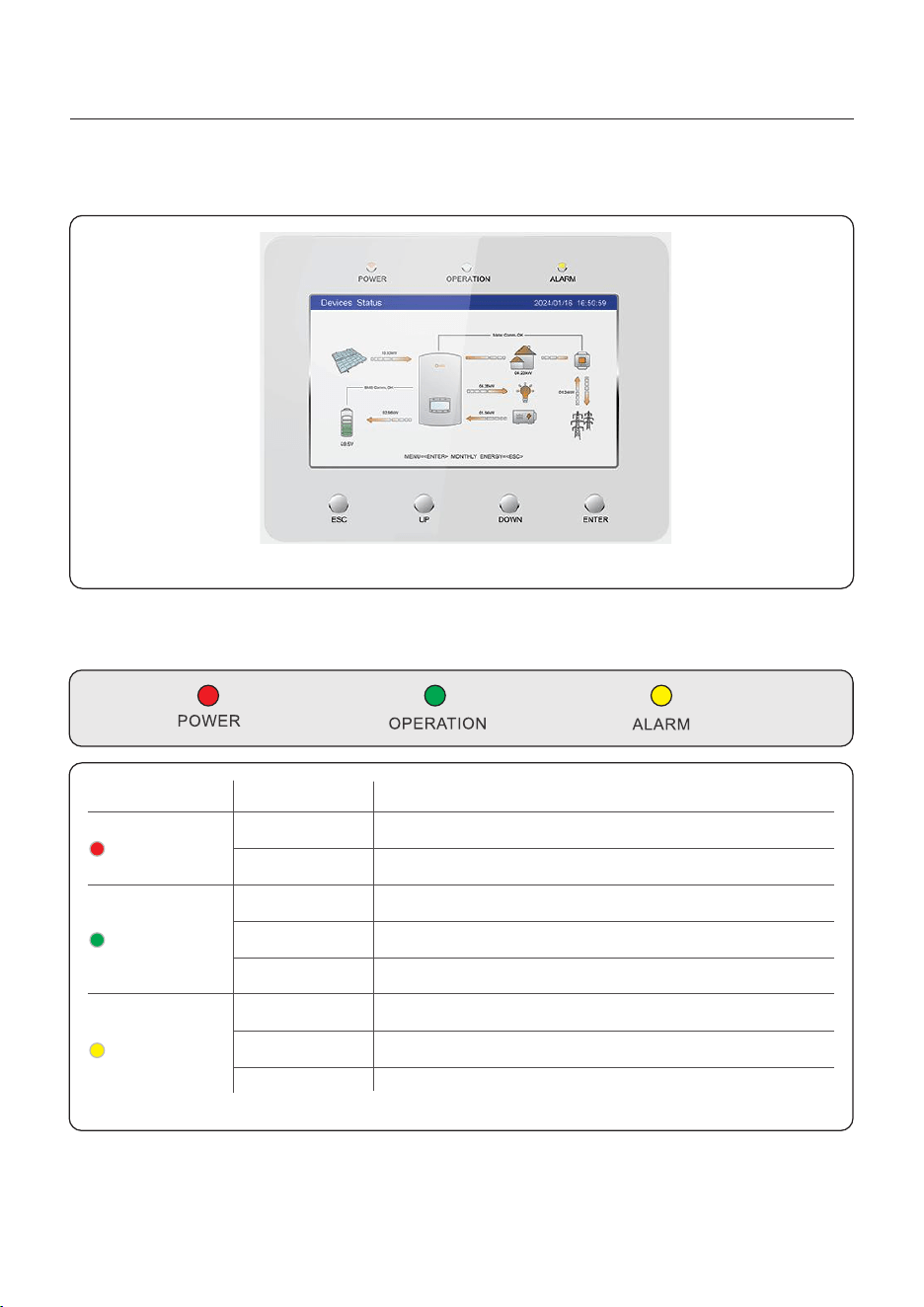
36
Description
The inverter can detect DC power.
No DC power.
The inverter is fully operational.
The inverter has stopped operating.
The inverter is initializing.
Emergency Fault.
No fault condition detected.
Status
ON
OFF
ON
OFF
OFF
ON
FLASHING
Light
POWER
OPERATION
ALARM
There are three LED indicators on the RHI inverter (Red, Green, and Orange) which
indicate the working status of the inverter.
Table 4.1 Status Indicator Lights
FLASHING
Warning and Normal Fault.
User Manual
4. Overview
4.1 HMI Screen
There are 3 indicators and 4 operation button on the Solis S6 Series Inverter.
37
User Manual
4. Overview
4.2 Inverter built-in Bluetooth description
Bluetooth: BLE
frequency band(s) in which the radio equipment operates:2.402-2.480GHZ
Maximum transmitting power: 8dBm
Hereby, Ginlong Technologies Co.,Ltd.declares that the radio equipment type hybrid
inverter is in compliance with Directive 2014/53/EU
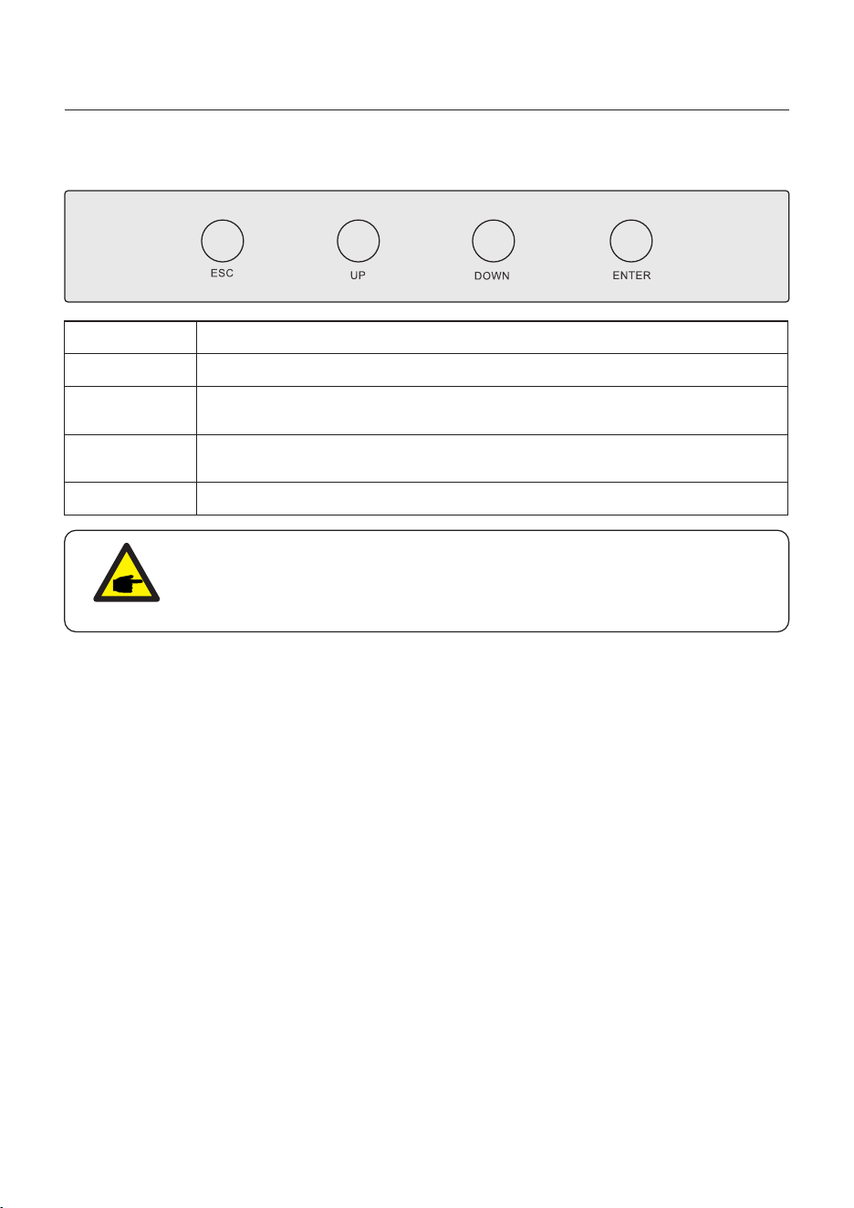
Button
ESC
UP
DOWN
Description
“Escape”, allows the user to exit, or cancel the operation.
Upwards key, allows the user to increase the value or move forward to the
next option.
Downwards key, allows the user to decrease the value or move backward
to the previous option.
ENTER Running or executing command .
NOTE:
The screen will be automatically turn off after being idle for a few minutes to
save power, click any operation button(“ESC”/“UP”/“DOWN”/ “ENTER”) to
restart the screen, then press“Enter”into the main operation interface.
Description of buttons:
38
5. Commissioning
User Manual
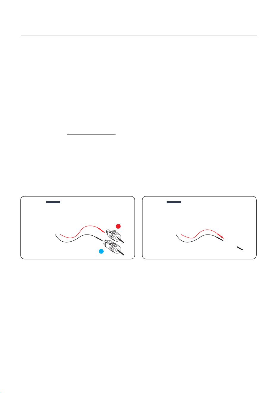
5.1 Pre-Commissioning
+
-
Measure DC voltage of
PV strings and battery
Measure AC voltage
and frequency
● Make sure that no high voltage conductors are energized.
● Check all conduit and cable connection points ensure they are tight.
● Verify that all system components have adequate space for ventilation.
● Follow each cable to ensure that they are all terminated in the proper places.
● Ensure that all warning signs and labels are affixed on the system equipment.
● Verify that the inverter is secured to the wall and is not loose or wobbly.
● Prepare a multimeter that can do both AC and DC amps.
● Have an Android or Apple mobile phone with Bluetooth capability.
● Install the Soliscloud APP on the mobile phone and register a new account.
● There are three ways to download and install the latest APP.
1. You can visit www.soliscloud.com.
2. You can search”Soliscloud”in Google Play or APP Store.
3. You can scan this QR code to download Soliscloud.
5.2 Power ON
Step 1: With the DC switch off, energize the PV strings and then measure DC voltage of the
PV strings to verify that the voltage and polarity are correct. Turn on the battery and check
the battery voltage and polarity as well.
Step 2: Turn on the OCPD for the system and then measure the AC voltages line to line
and line to neutral. The backup side of the system will be off until commissioning is complete.
Turn the OCPD back off for now.
Step 3: Turn the DC switch on and then the OCPD(AC breaker) for the system.
This inverter can be powered on by PV only, battery only and Grid only.
When the inverter is powered on,the five indicators will be lighted at once.
5.3 Power OFF
Step 1: Turn off the AC breaker or AC disconnect switch to disable AC power to the inverter.
Step 2: Turn off the DC switch of the inverter.
Step 3: Turn off the battery breaker.
Step 4: Use a multimeter to verify that the battery and AC voltages are 0V.
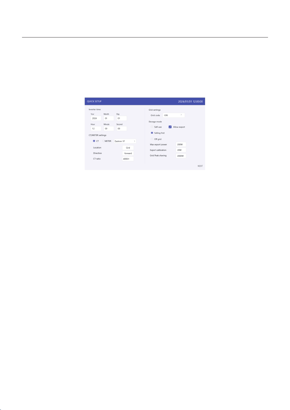
If this is the first time the inverter has been commissioned, you will need to first go through
the Quick Settings. Once this has been done, these settings can be changed later.
Inverter Time -> Meter Setting -> Grid Code -> Storage mode -> Battery Model
5.4 HMI Screen Setting
5. Commissioning
User Manual
39
1. Inverter time:
Set inverter time and date, default follow the phone.
2. CT/Meter setting:
Select the CT or Meter, Solis provide Eastron 3 phase meter, it is self-identifiable.
Set installation location: Grid side / Load side / Grid+PV inverter;
CT direction: When CT installed correctly, select “Forward”; when CT installed direction
wrong, the sampling current of CT will be reversed when calculating the power, select
“Reversal” to correct it.
Set CT ratio: default 60 (Solis provide ESCT-T50-300A/5A CT), if the user install their own CT,
then need to set the CT ratio manually. If the system connected to Meter, then CT ratio need
to be set on Meter.
3. Grid code:
Select grid code that meet the local regulations.
4. Storage mode:
ALL modes first priority is to use the available PV power to support loads. The different
modes determine what the second priority, or use of the excess PV power, will be.
Self-use / Selling first / Off-grid are exclusive, the user could select only one mode.
5.4.1 HMI Quick Setting
5. Commissioning
User Manual
40
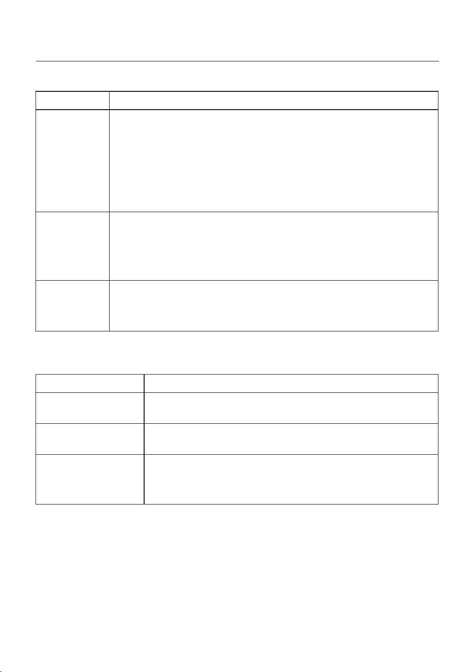
Mode
Self-use
Selling first
Off grid
Description
PV power flow priority sequence: loads > battery > grid.
In this mode, the system stores excess PV power into the battery after
the loads are supplied.
If “Allow export” turned on, when the battery is charged full, or there is no
battery, the excess PV power will be exported(sold)back to the grid.
If the system is set to not export any power, then the inverter will curtail
the PV power (derate the inverter output power).
PV power flow priority sequence: loads > grid > battery.
In this mode, the system exports any excess PV power after the loads
are supplied. If the export power quota has been met, then the remaining
PV power will be stored in the battery.
Notice: This mode should not be used if export power set to zero.
PV power flow priority sequence: loads> battery.
This mode only used when the system are not electrically connected to
the grid at all. This mode is like Self-Use Mode, but the PV power will be
curtailed if the PV power output is> battery power + load power
Table 1 Description of modes
Under each mode, user could set other functions based on their requirements.
Settings
Max export power
Export calibration
Grid peak shaving
Description
Default: 1.1 times of rated power.
Notice: if feed-in is not allowed, set Max export power to 0.
Range : -500w-500w, default 20w, settable.
To compensate the deviation of CT/Meter in practical application.
Default enable, default 2 times of rated power.
Limit the power drawn from the grid to prevent from exceeding
regulatory requirements or the power line capacity.
It works only when the “battery reserve” turned on.
Table 2 Description of mode settings
5. Commissioning
User Manual
41
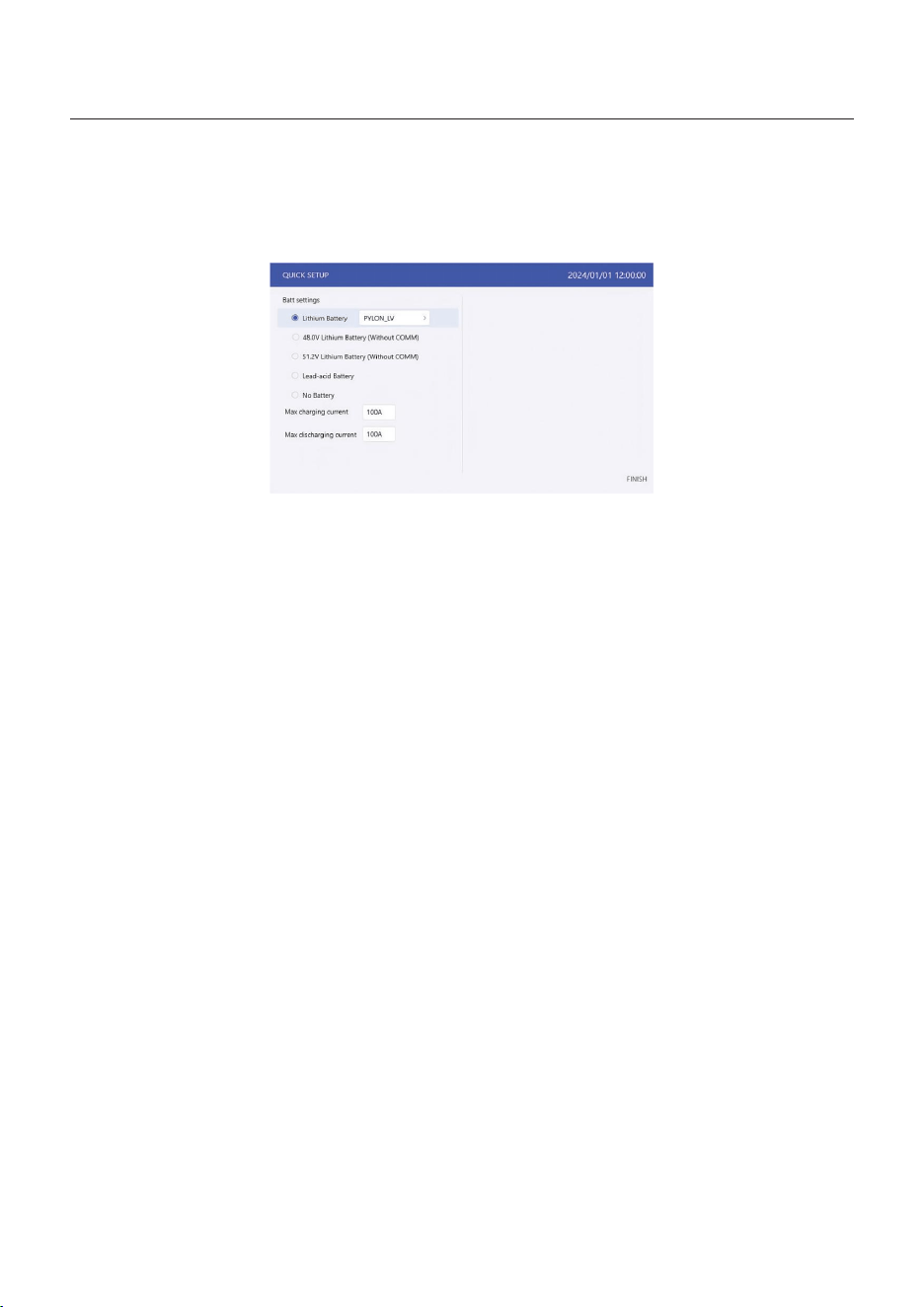
5. Battery setting:
Select battery brand.
Set Max charging/discharging current.
5. Commissioning
User Manual
42
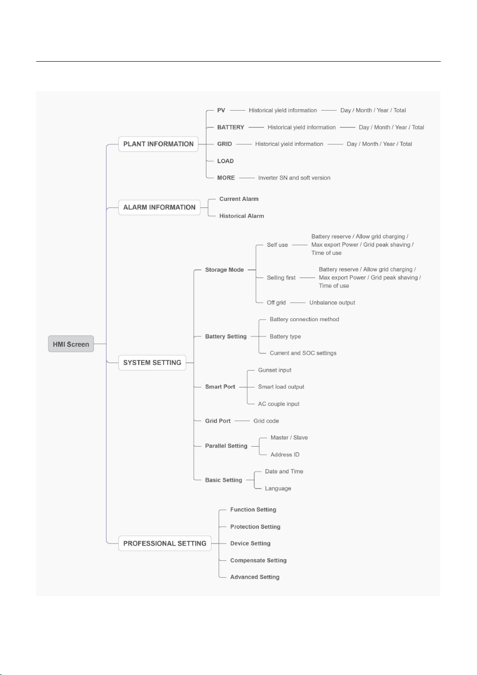
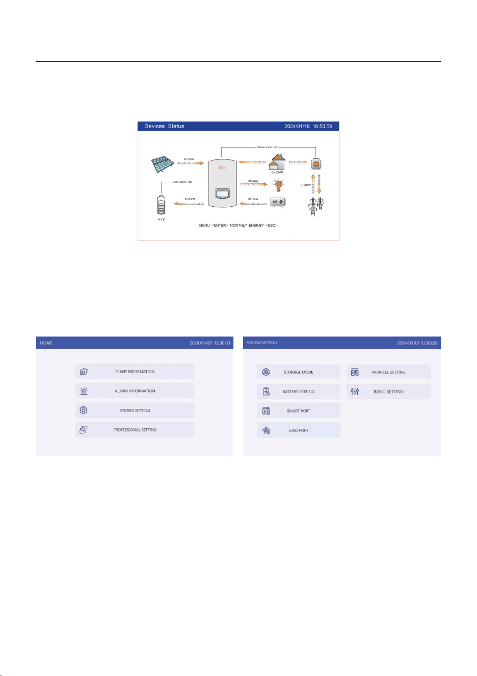
5.4.2 HMI screen operation system overview
5. Commissioning
User Manual
43
5.4.3 Detailed HMI Setting
Step 1: Enter Home page
After quick setting, press “ENTER”, the screen displays the home page.
The screen will be automatically turn off after being idle for a few minutes to save power,
click any operation button(“ESC”/”UP”/”DOWN”/ “ENTER”) to restart the screen, then press
“Enter” into the main operation interface.
Step 2: Enter “SYSTEM SETTING” interface
Press“Down” button, then press “ENTER” into the “SYSTEM SETTING” interface.
5. Commissioning
User Manual
44
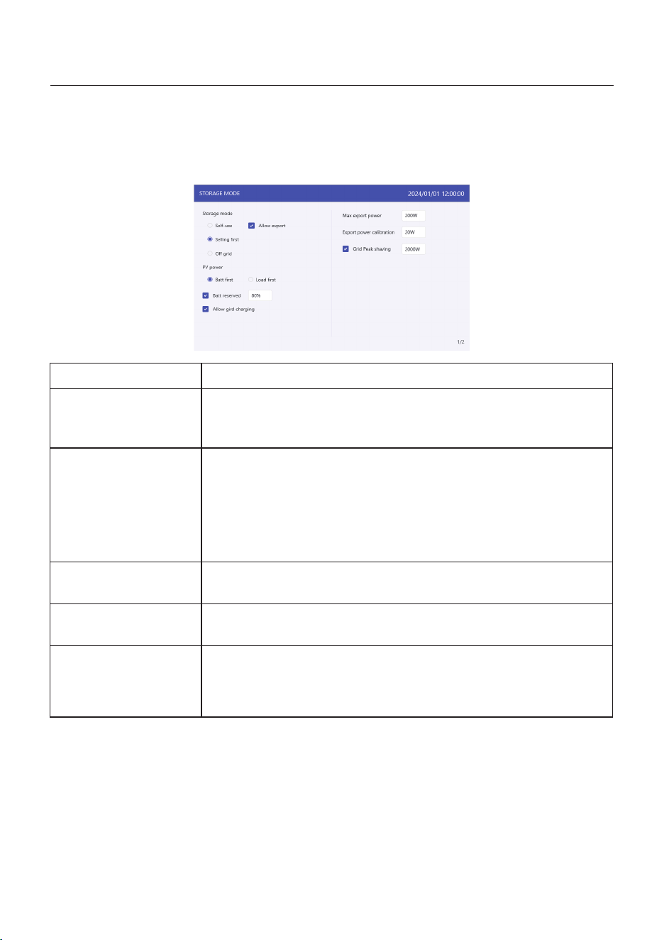
Step 3: Set “Storage Mode”
Use “UP” or “DOWN” key to select the desired mode, then press “ENTER”.
The Mode description please refer to 5.4.1.
Settings
Battery reserve
Allow grid charging
Max export power
Export calibration
Grid peak shaving
Description
Range: 5~95%, default: 80%, settable.
When battery SOC < set battery reserve SOC, battery will stop
discharging.
Allow grid charging the battery when it enables.
Notice: if “Allow Grid Charging” is turned on, the inverter will use
grid power to charge the battery only under two circumstances:
The battery drains to the Force Charge SOC.
When PV power output can’t meet the set current value during
the charge periods.
Default: 1.1 times of rated power.
Notice: if feed-in is not allowed, set Max export power to 0.
Range : -500w-500w, default 20w, settable.
To compensate the deviation of CT/Meter in practical application.
Default enable, default 2 times of rated power.
Limit the power drawn from the grid to prevent from exceeding
regulatory requirements or the power line capacity.
It works only when the “battery reserve” turned on.
Table 3 Description of storage mode settings
45
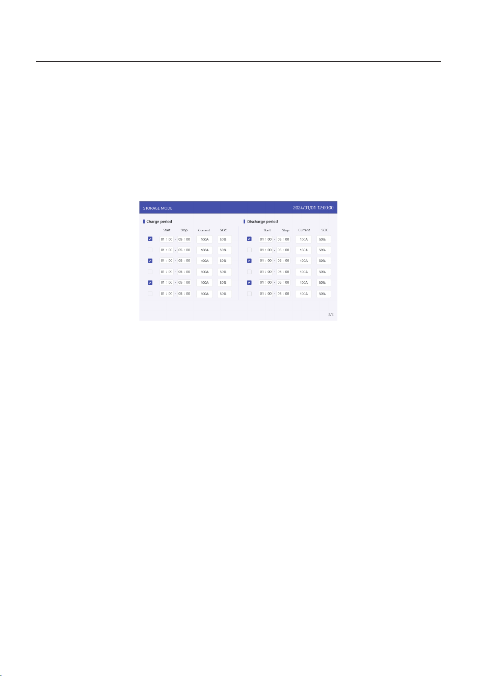
Step 4: Set “Time of use” under each mode (Skip this step if no need)
Time of Use is for manual control of the battery charging/discharging. It is for customizing
when the battery is allowed to charge and discharge power and at what rate, established by
a current(amperage)setting.
1. Charge period: battery charges with set current value until the charging cut-off voltage
(settable), checking the box to control whether enable this charging period.
2. Discharge period: battery discharges with set current value until the discharging cut-off
voltage (settable), checking the box to control whether enable this discharging period.
5. Commissioning
User Manual
5. Commissioning
User Manual
46
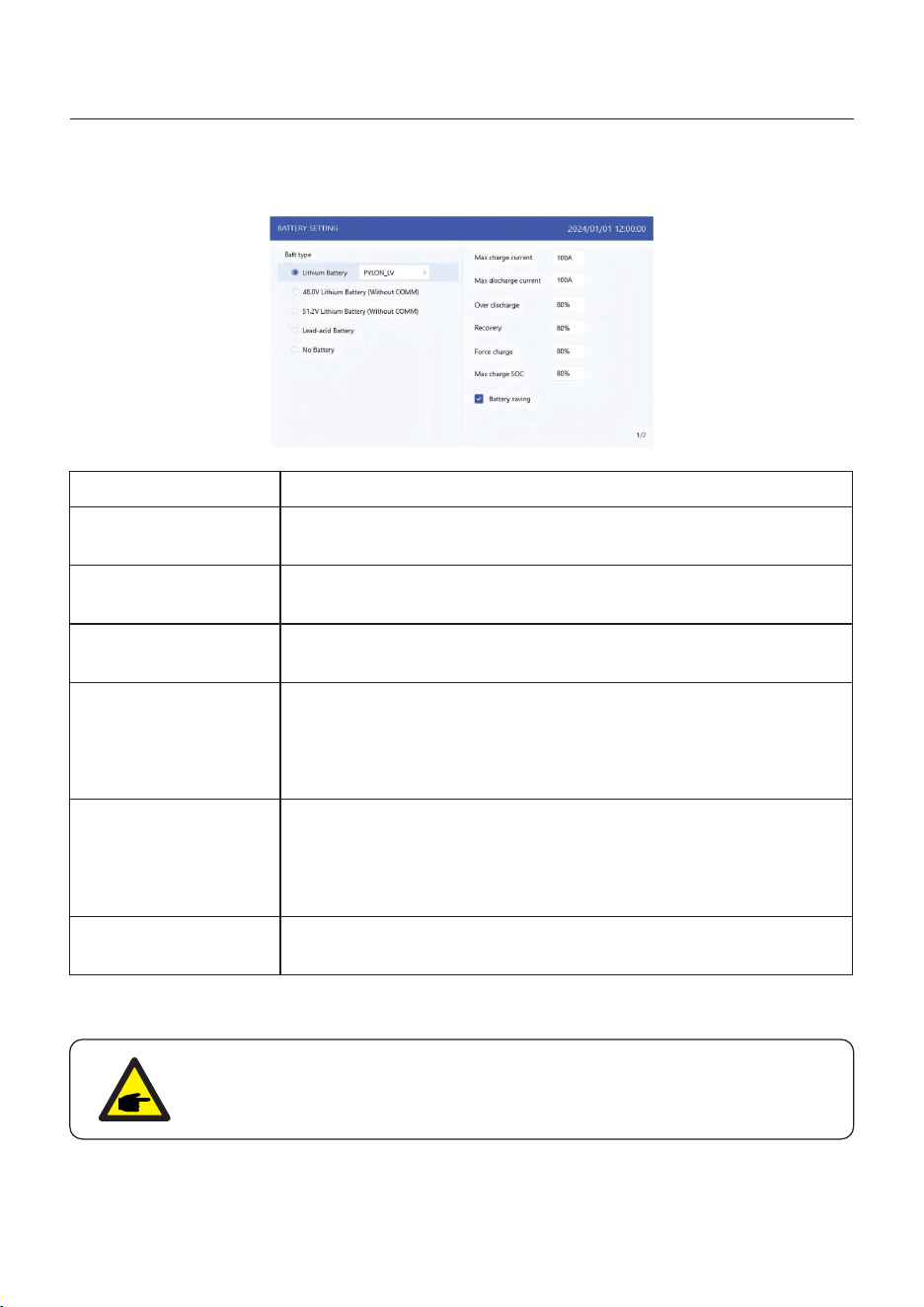
Step 5: Set “Battery Setting”
Settings
Max charge current
Max discharge current
Over discharge
Recovery
Force charge
Max charge SOC
Description
Max charge current, settable.
Max discharge current, settable.
Range: 5~40%, default 20%,
when battery SOC < over discharge, it will stop discharging.
Charge cut-off SOC, battery stops charging when reach the
Max. Charge SOC.
Table 4 Description of battery mode settings
NOTICE:
Force charge SOC < Over discharge SOC < Recovery SOC, otherwise the
setting might be error.
Range : set Over discharge value +1% ~ set Over discharge
value +20%;
when battery SOC < Recovery SOC, it will start charging,
reserve the return difference value to avoid the battery
repeatedly cross jump between charging and discharging.
Range : 4%~ set Over discharge value,
when battery SOC < force charge SOC, the grid will charge the
battery.
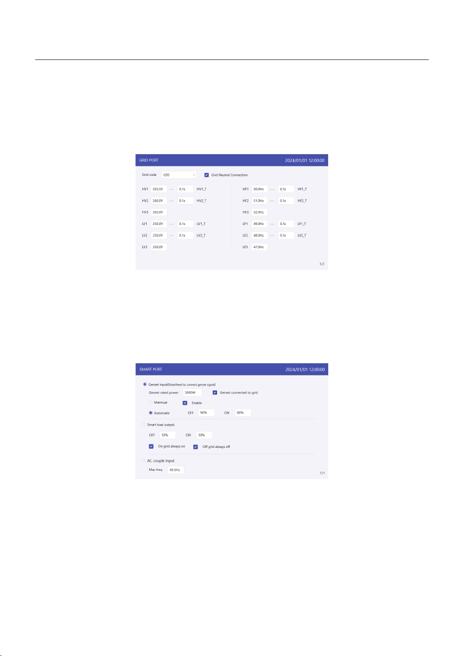
Step 6: Set “Grid Port”
(Skip this step if grid code is already set in quick setting)
Select grid code that meet the local regulations.
Three level of Over-voltage / under-voltage / Over-frequency / under-frequency are default
based on grid code, there is no need to set the parameters in manual.
5. Commissioning
User Manual
47
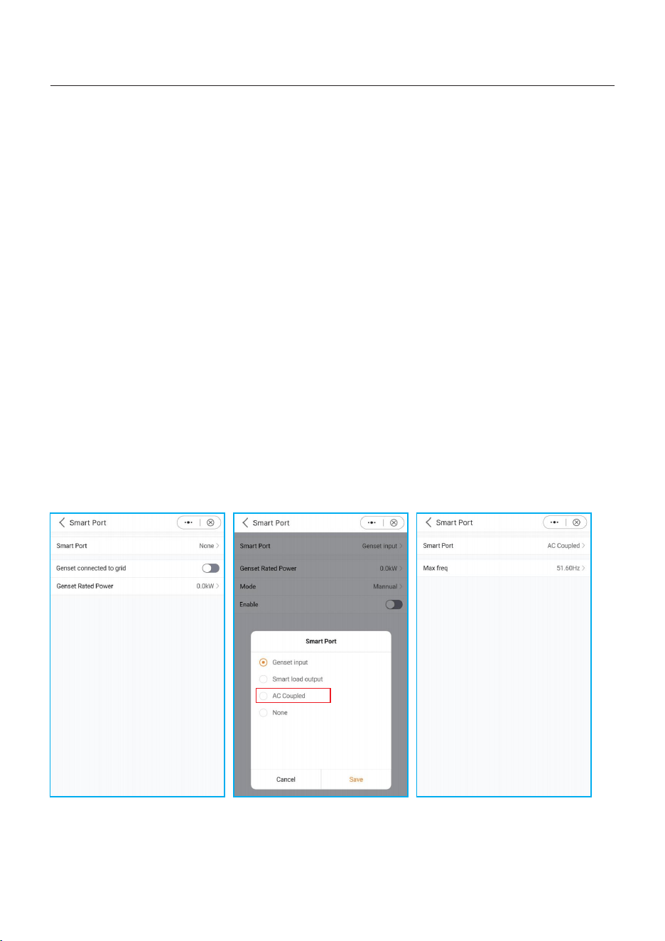
Step 7: Set “Smart Port”
(Skip this step if the system is not connected to generators)
When it is connected to Generator, select “Gunset input”;
When it is connected to smart load like heat pump,select “Smart load output”
When it is connected to Grid-tied inverter,select “AC coupled”
Genset
The user need to input the “Genset rated power” by manual.
OFF: Generator stops charging SOC, settable, range:35~100%;
ON: Generator start charging SOC; settable, range:1~95%;
AC coupled:
OFF: Grid-tied inverter stops charging SOC, settable, range:35~100%;
ON: Grid-tied inverter start charging SOC; settable, range:1~95%;

5. Commissioning
User Manual
48
Step 8: Set parallel system
Set Master and Slave machine,
Set Master ID as: 1
Slave machine ID as: 2
.Slave machine ID as: 3
..... and so on.
49
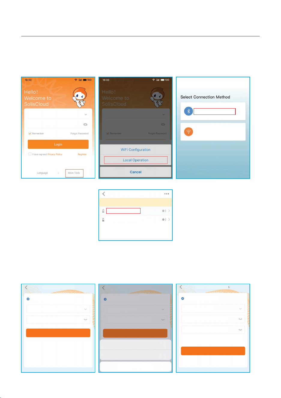
5.5 Log in the APP via Bluetooth
5. Commissioning
User Manual
Step 1: Connect with Bluetooth.
Turn on Bluetooth switch on your mobile phone and then open the SolisCloud APP.
Click “More Tools”->”Local Operation”->”Connect with Bluetooth”
Step 2: Select the Bluetooth signal from the inverter. (Bluetooth Name: Inverter SN)
Step 3: Login account.
If you are the installer, please select the account type as Installer. If you are the
plant owner, please select the account type as Owner. Then set your own initial password
for control verification. (The first log-in must be finished by an installer in order to do the
initial set up)
xxxxxxxxxxxx
xxxxxxxxxxxx
Control Verification
Select account type
Enter password (6-characters)
Verify
Control Verification
Installer
Enter password (6-characters)
Enter password again
Please set the password of the installer’s account
before continuing
Set Enable
<
xxxxxxxxxxxx
Control Verification
Select account type
Enter password (6-characters)
Verify
Installer
Owner
Cancel
<
<
Local Operation
Connect With Bluetooth
Connect With WiFi
<
Nearby Device
If the dev ic e is not in the list, please cl ic k th e “Search Device”
button a t th e bottom or drop-down to re fr es h the page
xxxxxxxxxxxx
xxxxxxxxxxxx
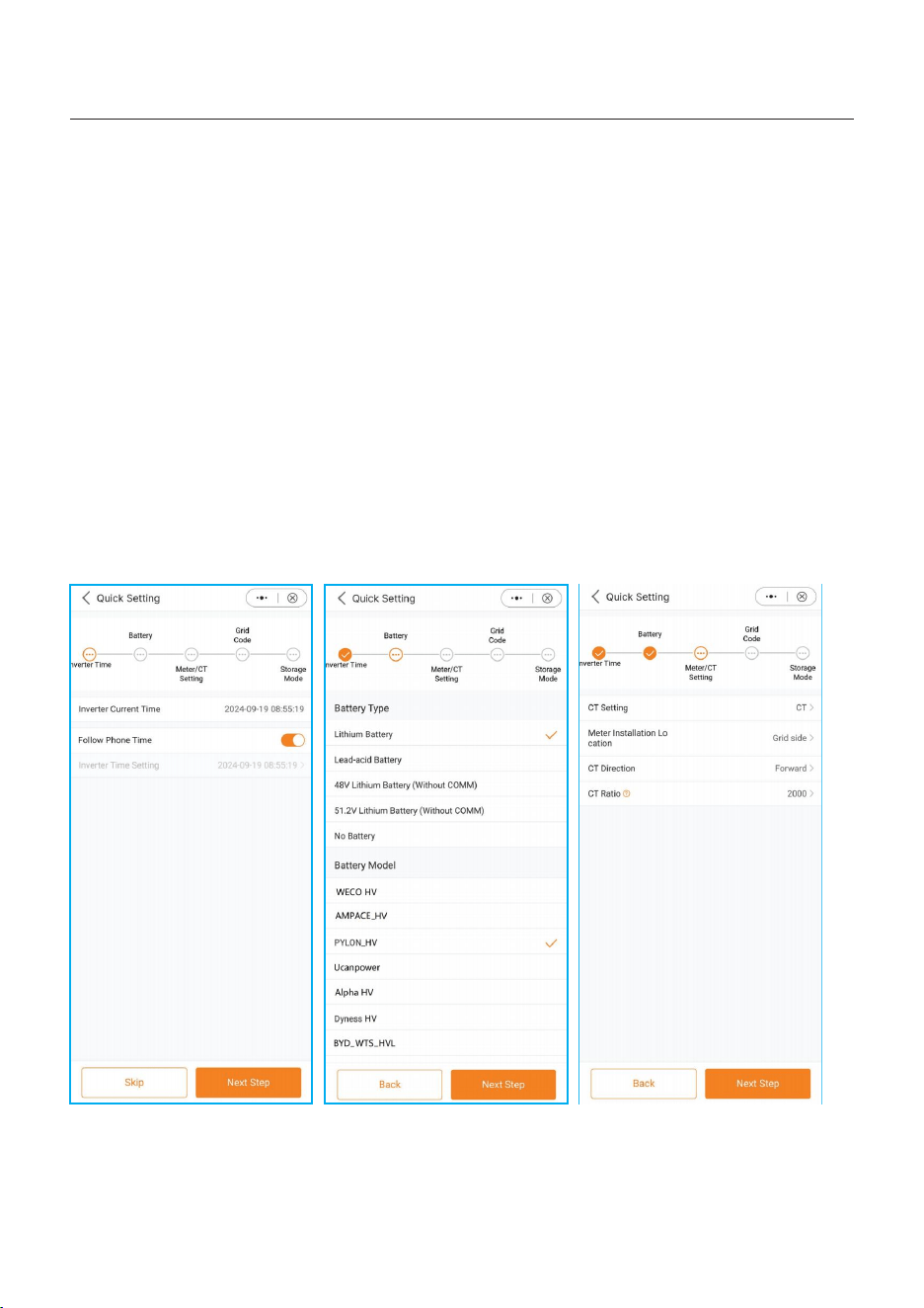
Step 4: After the log in for the first time, initial settings are required.
Step 4.1: Set the inverter date and time.
You can set to follow the time on your mobile phone.
Step 4.2: Set the battery model.
It must be based on the battery model that is actually connected to the inverter.
If there is no battery connected for the moment, please select “No Battery” to avoid
alarms.
The default setting for battery over discharge SOC is 20%, force charge SOC is 10%.
Step 4.3: Set the meter setting.
It must be based on the meter type that is actually connected to the inverter.
If the grid does not need to be connected to an N-Line, select disconnected
If there is no meter connected for the moment, please select “No Meter” to avoid alarms.
It is suggested to install the meter at the system grid connection point and select “Meter in
Grid”.
Step 4.1 Step 4.2 Step 4.3
50
5. Commissioning
User Manual
5.6 Shutdown procedure
Step 1. Turn off the AC breaker at the grid connection point.
Step 2. Turn off the DC switch of the inverter.
Step 3. Turn off the battery breaker.
Step 4. Wait until the device is powered off, and the system shutdown is complete.
Step 4.4 Step 4.5
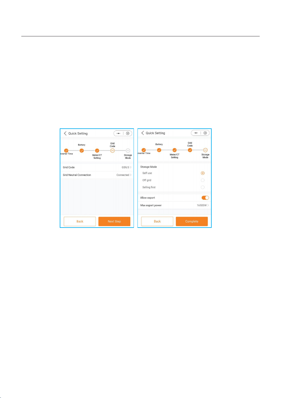
Step 5: Setup complete.
Now the initial settings on the inverter have been set and you can switch on the inverter’s
DC switch and switch on battery breaker to start up the system. You can also explore in
the APP to check the operating data, alarm message or other advanced settings.
Step 4.5: Set the work mode setting.
Recommended setting is Self-Use Mode. This mode will maximize the use of PV power
generation for household electricity, or store it in batteries and use it for household
electricity.
Allow export: Allow power output to the grid in Self-use mode. If you do not want to send
power to the grid, do not turn it on.
Max export power: Limit the maximum power sold to the grid.
Step 4.4: Set the grid code setting.
Please select the grid code based on the local grid network requirements.
51
5. Commissioning
User Manual
5.7 Work Mode and Settings
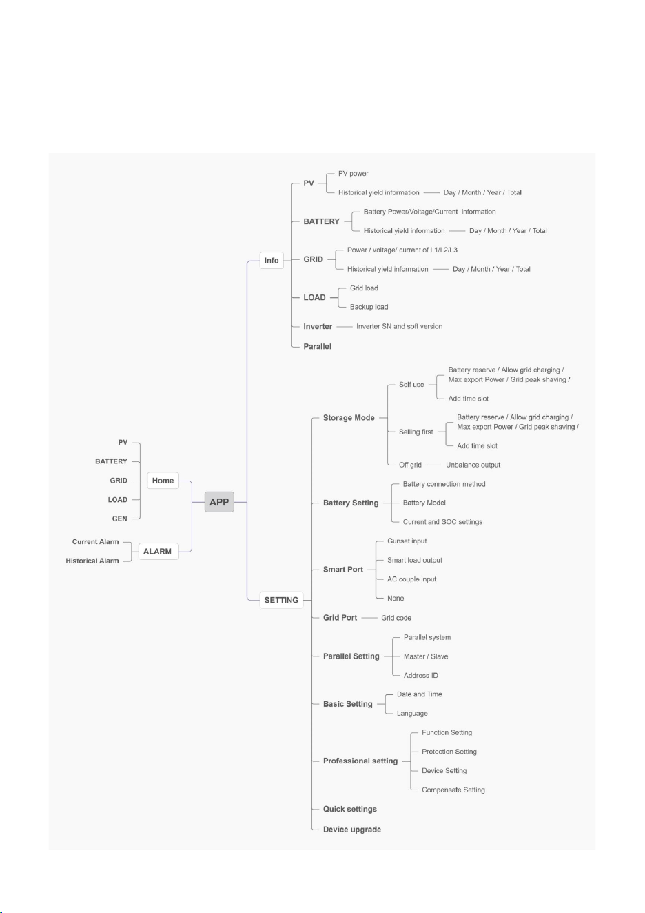
APP operation system overview
52
5. Commissioning
User Manual

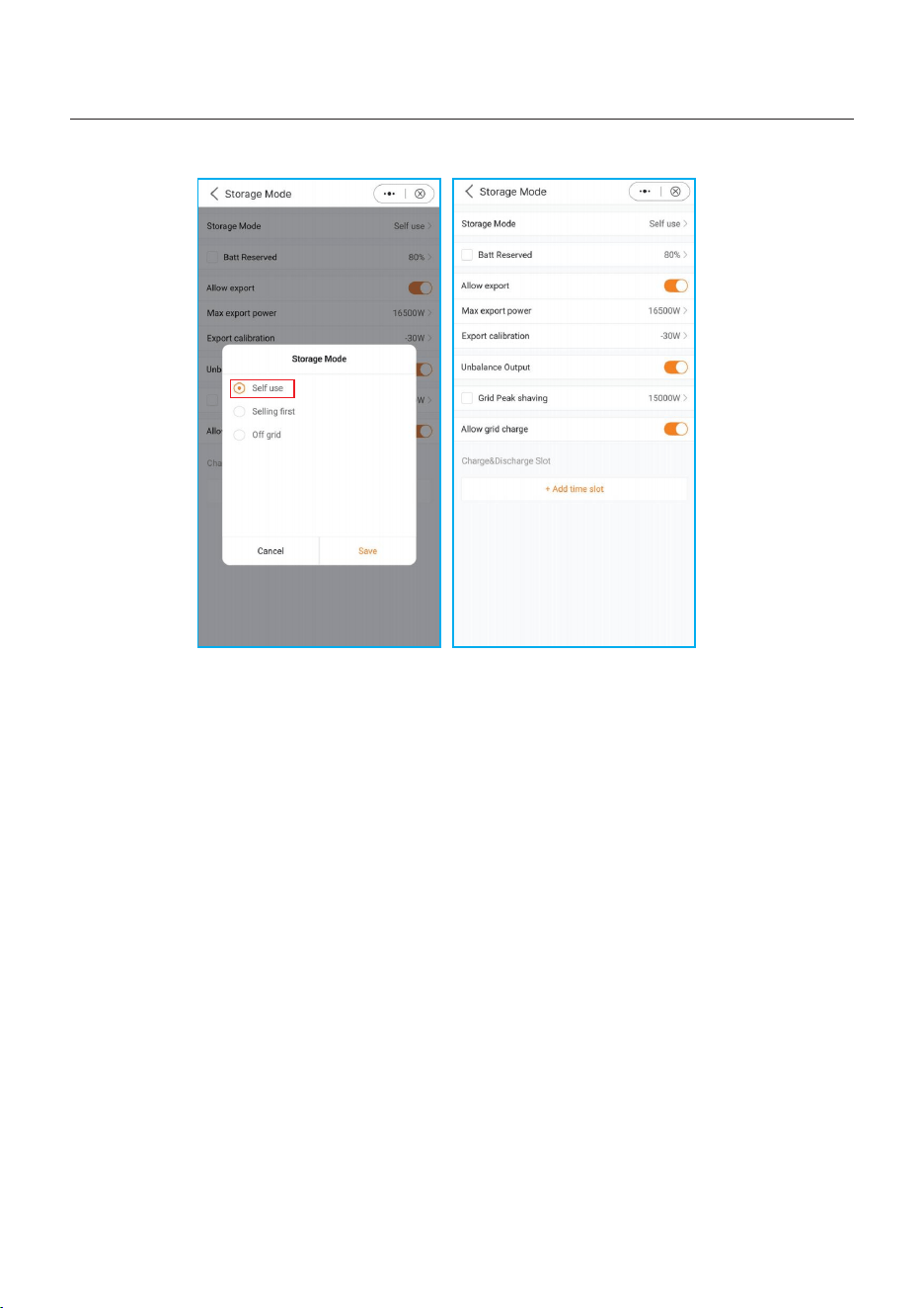
5.7.1 Self-Use mode
How to set Self-Use mode?
53
5. Commissioning
User Manual
Load priority: load>battery>grid
Power supply priority: PV>battery>grid>DG
This mode applies to the area that has low feed-in tariff and high energy price.
The PV power will prioritize supplying energy to the load and charging the battery, with
any surplus power being fed into the grid. During periods without PV power at night or
when the PV power is insufficient, the battery will discharge to support the load.
•Supports TOU settings in this mode.
•Supports Battery Reserve function in this mode.
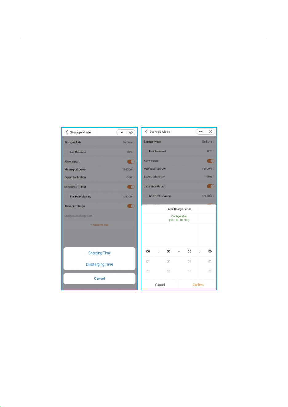
APP: setting--storage mode-self use
A. Self-Use Mode is activated without any specific times set for the battery to be
charged/discharged, and the battery reserve is not switched on.
Note: Solis recommends activating the 'Allow Grid Charge' option. Once the battery
reaches the Forcecharge SOC, it will use the grid to charge the battery, preventing it
from being deep discharged.
B. The Self-Use Mode provides you with the option to set a Battery reserve value.
Please toggle the switch to activate the battery reserve mode.
C. The Self-Use Mode provides you with the option to set whether allow power output
to the grid and the max value.
D. If there is an error with your meter or CTs, open "Export power calibration" to calibration;
In addition, you can set a small negative value(like:-50W)to ensure that no power is sent
to the grid to achieve Zero export Power.
E. When your load is unbalanced in the three-phase distribution, turn on unbalanced output.
Supports 150% Unbalanced Loads on both the Grid and Backup Port, single-phase load
1/2 rated power.
F. You can set the value of Grid peak shaving, Limit the power that inverters can obtain from
the grid to prevent exceeding regulatory requirements or the power line capacity due to
excessive power.
G. With the Add time slot, you can customize 6 stages of charging and 6 stages of discharging
in one day.
Batt reserved: Lithium battery: default 80%, adjustable range (the recommended value
is more than 80%, to ensure that the battery has enough energy to supply the load after
the grid is off ;
Lead acid battery: Default 100%, cannot be set.
Allow export: Allow power output to the grid in Self-use mode. If you do not want to send
power to the grid, do not turn it on.
Max export power: Limit the maximum power sold to the grid.
Export power calibration: As some CTs/meters may have errors in practical applications,
this setting value can be used for compensation. The range is "-500w ~ +500w"
Unbalanced output: Allow three-phase output imbalance, single-phase maximum load
50% of rated power.
Grid peak shaving: Limit the power that inverters can obtain from the grid to prevent
exceeding regulatory requirements or the power line capacity due to excessive power.
When the grid supplies power to the load while charging the battery, it will limit the power
used to charge the battery, so that the total power does not exceed the set value.
If the grid only supplies power to the load and does not charging the battery, it is not limited
by the setting value.
Allow grid charging: Allow the battery to be charged by the grid.
Charge/Discharge Slot: When the time is between Start and Stop, the system will charge/
discharge the battery according to the set Current until the set "SOC/voltage" is reached.
54
5. Commissioning
User Manual
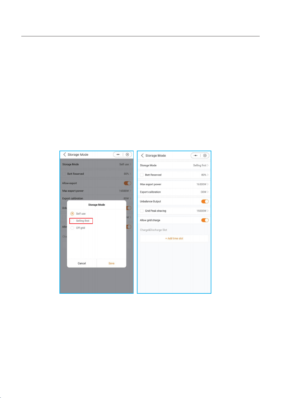
5.7.2 Selling first mode
Load priority: load>grid>battery
Power supply priority: PV>battery>grid>DG
This mode applies to the area that has high feed-in tariff and export control.
The PV power will prioritize supplying energy to the load. Then any surplus is directed
into the grid.
If there is a feed-in limitation, the excess power will charge the battery.
•Supports TOU setting in this mode.
•Supports Battery Reserve function in this mode.
55
5. Commissioning
User Manual
How to set selling first mode?
APP: setting--storage mode--selling first
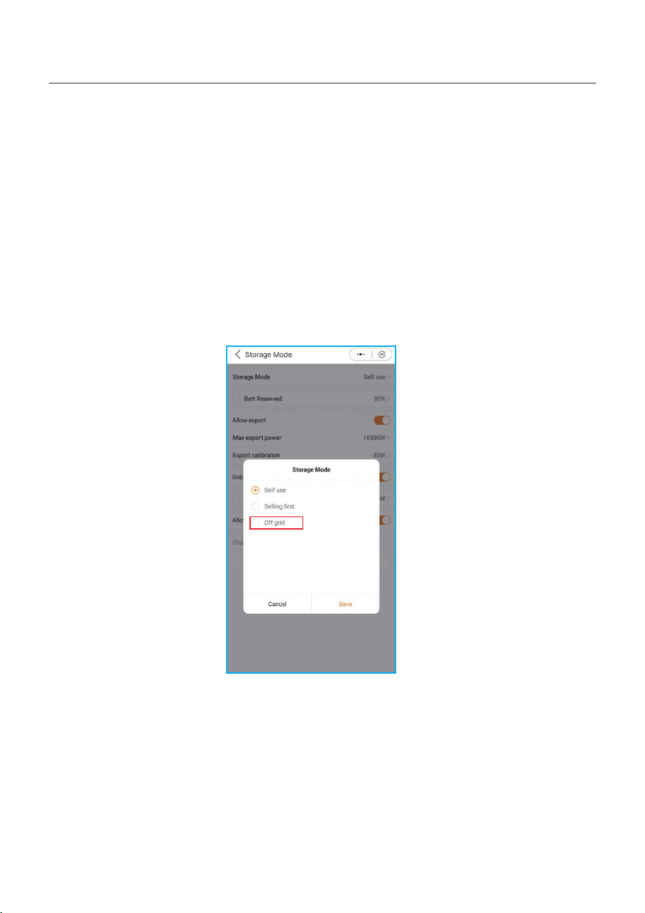
5.7.3 Off-Grid mode
Load priority : load>battery
Power supply priority: PV>battery>DG
•This mode applies to the area not covered by the grid or when the system is not connected
to the grid.
•When a power outage is detected in a grid-tied system, the system will automatically will
automatically enter in the off-grid, supplying only the backup load.
•The user can also manually set this mode, supplying only the backup load.
56
5. Commissioning
User Manual
How to set Off-Grid mode?
APP: setting--storage mode--off-grid
5.8 TOU Function Settings
This function applies to the area with peak-valley price. Set the system to charge the battery
in valley price and discharge in peak price to improve benefits.
Supports 6 customizable charge/discharge time settings, while the battery will charge/
discharge at a set current.
Supports TOU function settings in self-use mode, feed in priority mode.
There are 6 customizable charging settings and 6 customizable discharging settings.
How to set TOU Function?
Press“+Add Time Slot”to add a charging/discharging time period.
57
5. Commissioning
User Manual
5.9 Battery Settings
The battery section of the app offers numerous options to customize the interaction
between the inverter and the battery. Here, we provide explanations for the functions
and features available in this section, allowing users to tailor the inverter's behavior to
their specific preferences and requirements.
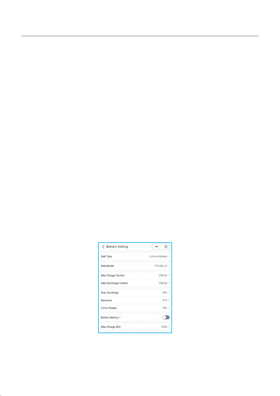
Battery Type: Please select the correct Type of the battery. Lead-acid battery and lithium
battery.
Battery Mode: Please select the correct model of the battery. If you don't have a battery,
choose "No battery" to ensure accurate configuration.
Max Charging/Discharching Current: Choose the maximum charge/discharge current
that you wish to. This selection allows you to customize the charging and discharging
parameters based on your preferences and requirements.
Overdischarge SOC: The Overdischarge SOC (State of Charge) is the minimum battery
charge level to which the inverter will discharge. It acts as a safeguard to prevent the
battery from discharging beyond this specified threshold, ensuring its longevity and health.
Recovery: The battery can discharge when the SOC/Voltage reaches the set value.
Forcecharge: The Forcecharge SOC for the battery is the minimum state of charge(SOC)
at which the inverter initiates charging the battery from the grid. It specifies the threshold
below which the inverter actively engages in recharging the battery to maintain optimal
performance.
Battery saving: Reduce battery loss. The necessary power for the operation of the inverter
preferentially obtains from the grid, not from the battery.
Max charge SOC: The maximum SOC/Voltage that the battery can be charged to.
Default 100%. Some batteries may alarm overvoltage when fully charged, and limiting
protection will not be triggered if not fully charged.
58
5. Commissioning
User Manual
5.10 Battery Functions setting
If you need more Function Settings for the battery, you can go to Setting--Professional
Setting--Function Setting.
ECO function: To protect the battery, If PV power is lower than 100W and SOC below
overdischarge SOC, The inverter will take power from the grid instead of battery, to
maintain standby state,indicator and communication.
Battery Wakeup Switch: Battery wake-up can be supported in case of only PV or only
Grid. This function supports manual and automatic operation, the battery can be awakened
from the dormant state and charged above the overdischarge SOC.
Wake up voltage&time can be set:
Voltage: default 120V, range :120-600V;
Time: default 180s,range :20s-300s;
The wake up current depends on the battery, up to 6A.
Battery Healing Switch: When the lithium battery maintains low power for a long time,
the battery SOC measurement is not accurate,It is necessary to charge the battery to
100 % from low power level to ensure the healthy and stable operation of the battery.
Working logic: PV+grid charge the battery from Forcecharge SOC to overdischarge SOC ,
then grid stops charging, PV gives priority to charging the battery to Battery Healing SOC.
And the battery does not discharge before reaching the set Battery Healing SOC.
Battery Peak shaving: In this function, the force charge power will be dynamically
adjusted and not exceed the set value minus the load power when force charging.
59
5. Commissioning
User Manual
5.11 Smart port settings
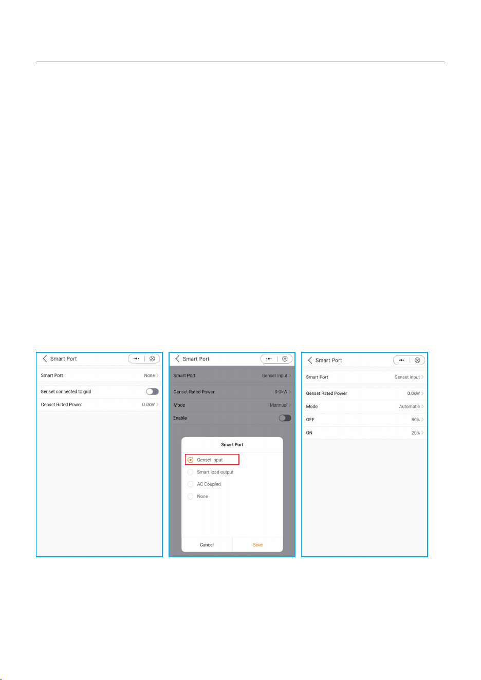
APP: setting--Smart Port
5.11.1 Generator setting
In single system, Diesel Generator can be connected via GEN port or ATS on Grid side.
If though GEN port, it will only supply power to the Backup load. It is recommended that
the power be greater than the backup load power.
If it is necessary to supply power to the grid side load, it is recommended that the generator
be connected through ATS on grid side;
In parallel-system scenarios, connecting DG via ATS is recommended, Gen port is also
supported;
When the generator is connected to the system, it is necessary to correctly select the
location of the generator to avoid system failure or generator damage.
A. Select Genset input
B. Set the Genset rated power.
C. When you want to manually control the start and stop of the generator, enable needs to
be selected.
D. When you want the generator to automatically start and stop according to the battery
SOC, please select the Automatic.
The generator will start when the battery SOC drops to the ON SOC, and stop when the
SOC reaches the OFF value.
60
5. Commissioning
User Manual
APP: setting--Smart Port
5.11.2 AC coupled setting
With an existing PV plant connected to the system, it is recommended that:
Grid-tied inverter power< rated AC power of S6 inverter.
In an on-grid scenario, when the third-party grid-connected inverter is connected, the
system cannot control the output power of the third-party grid-tied inverter, so feed-in
limitation cannot be achieved;
When connected in off-grid scenario, the third-party grid-tied inverter needs to set the
correct grid code, and has the function of over-frequency load shedding & under-frequency
load rising, so that the system can adjust the frequency to control the output power of the
grid-tied inverter.
When the system is connected to the generator, it cannot be connected to the grid-tied
inverter, as there’s a risk of damaging the generator.
A. Select the AC couple input.
B. Set the Max frequency according to the specification of the PV inverter.
The hybrid uses Freq-Watt to control the output of the PV inverter. Please consult with the
PV inverter’s manufacturer to confirm the correct setting procedures of its Freq-Watt
response first.
When SOC≤70%, start inverter, when SOC≥85%, Hybrid raises the frequency to the set
value, stop inverter.
61
5. Commissioning
User Manual
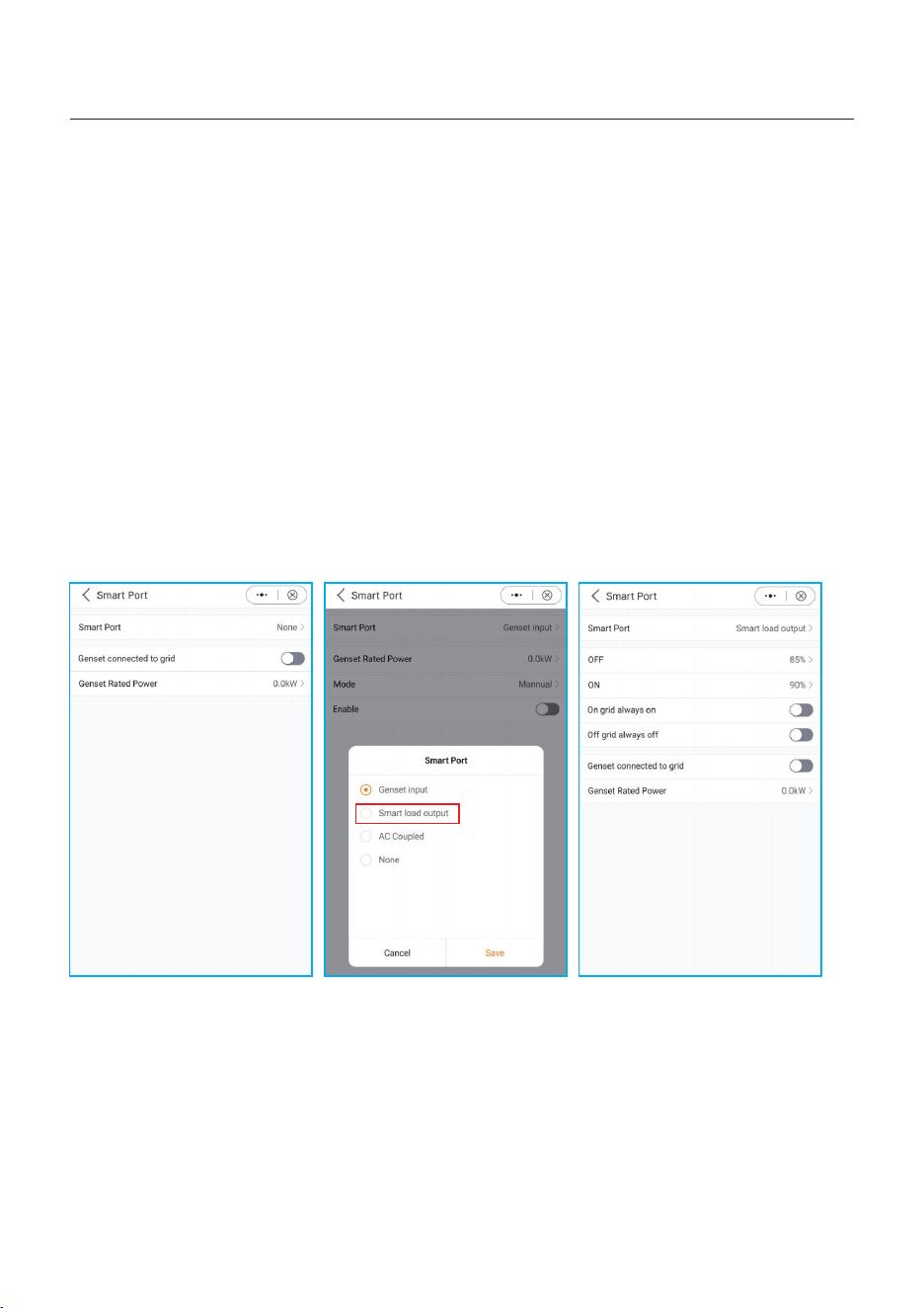
APP: setting--Smart Port
5.11.3 Smartload setting
The Gen port has extended power, which can be used as Smart load output. When the
battery SOC/Volt reach the ON set value, the smart port will supply power to the load.
When the battery SOC/Volt drops to OFF SOC/Volt, it will cut off the power of the load.
A. Select Smart load output.
B. Select On grid always on or Off grid always off
On grid always on: smart port will always supply power to smart load when the grid is
available.
Off grid always off: smart port will cut off power supply to smart load when the grid is off.
C.Set the OFF value and ON value to control the on/off of the load based on the battery
level.
When the battery SOC/Volt drops to the OFF SOC/Volt, the system will cut off the power
of smart load to ensure sufficient power for Backup load. When the battery SOC/Volt
reaches the ON SOC/Volt, the smart port will supply power to smart load.
62
5. Commissioning
User Manual
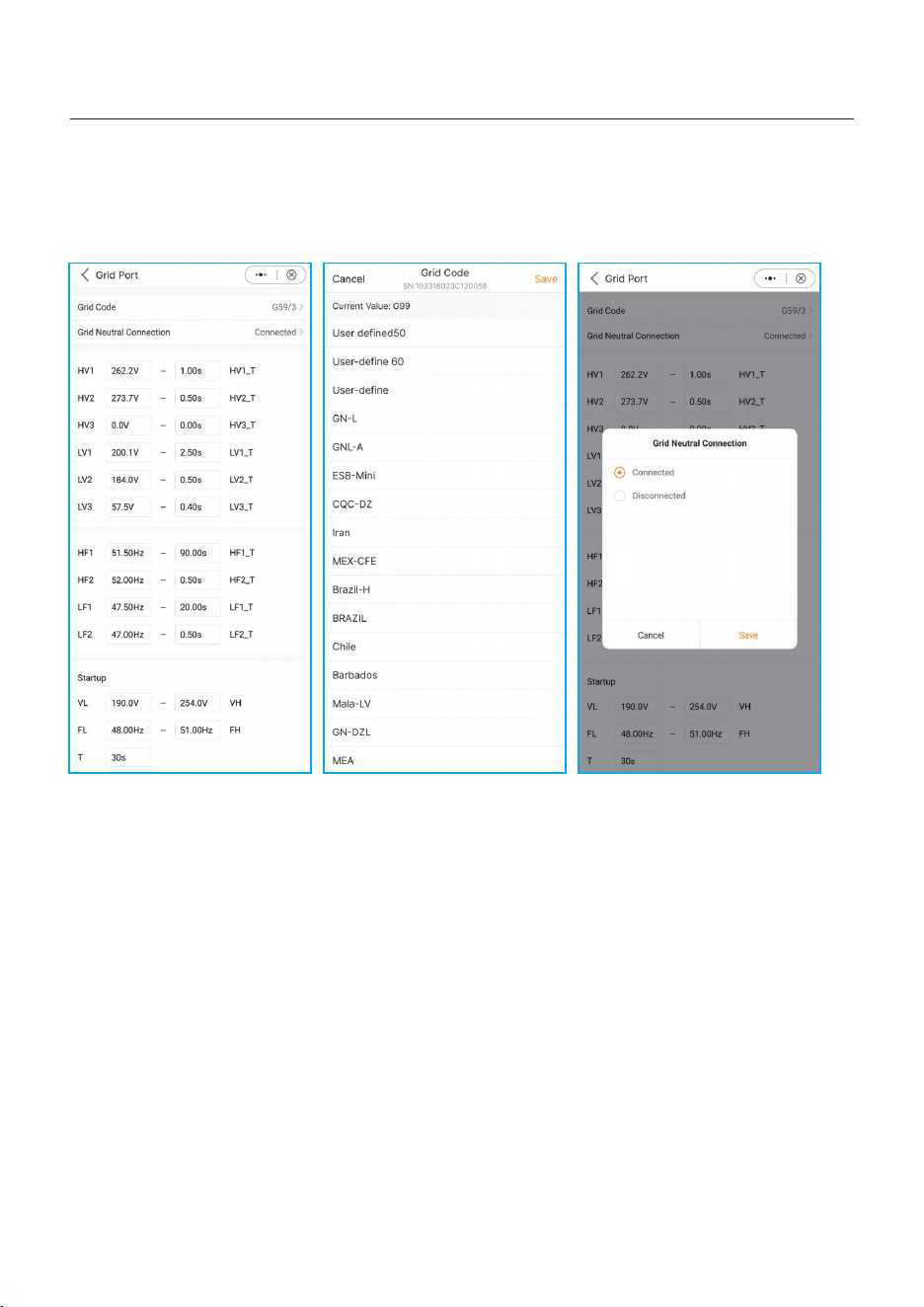
APP: setting--Grid Port
Select grid code that meet the local regulations; If the grid is three-phase and three-line,
choose Disconnected the N-line.
5.12 Grid port settings
63
5. Commissioning
User Manual
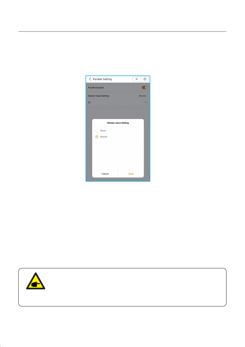
5.13 Parallel Settings
APP: setting--Parallel setting
The first inverter must be set as the Master.
The first inverter address is set to 1, the second to 2, and so on
(Note: that the address cannot be set to 0 and the physical address of the master must be 1)
5.14 Only PV power load function
1. Function Definition
For PV generation is not stable, the default setting of S6 energy storage machine don’t
support only PV power the load.
But for meeting the some customers’ special requirements, we develop the Only PV Power
Load function, when the PV power > the load power, you can use this function.
Because the PV power is not stable and the load is also not always stable, it is possible to
happen that PV power < load power, when it occurred, the load will shut down and after 3
minutes, the inverter tries to restart the load for the first time, after 5 minutes, the second
time, and after 10 minutes, the third time. If the third attempt to restart the load is still not
successful, the inverter will not try to restart, and it needs to be manually reset and restarted.
NOTE:
1. Only PV Power Load function is closed by default. If you need to use it,
you need to open it by yourself.
2. Software: Ensure that the current DSP and HMI software is the latest
version.
64
5. Commissioning
User Manual
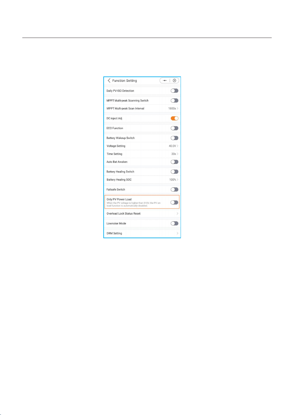
2. Solis APP Setting
Setting--Professional Setting--function Setting
65
5. Commissioning
User Manual
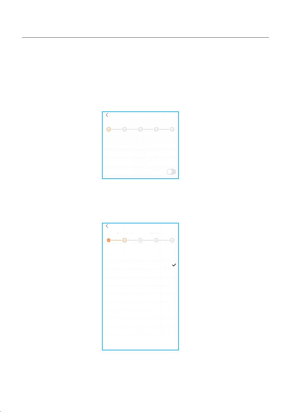
66
5.15 Initial set up
Inverter Time -> Battery Model -> Meter Setting -> Grid Code -> Work mode
A. Inverter Time: Set the Inverter Time and Date. It may be easier to tap the slider next to
“Follow Phone Time”.Then tap Next in the top right corner. This will set the inverter to
match your phone.
B. Battery Model: Now select the battery model connected to the inverter. This choice
must be based on the battery model that is actually connected to the inverter. If there is
no battery connected for the moment, select”No Battery”to avoid potential alarms codes.
Quick Setting
Next
Inverter Time Meter Type Working Mode
Battery Model Grid Code
Inverter Date Setting
Inverter Time Setting
Phone Time
Follow Phone Time
15:27
2023-04-11
2023-04-11 15:27:25
Quick Setting
Next
Inverter Time Meter Type Working Mode
Battery Model Grid Code
No Battery
PYLON_HV
B_BOX_HV BYD
Dyness LV
PureDrive-LV
LG Chem LV
AoBo-LV
JiaWei-LV
WECO-LV
FreedomWon-lv
Soluna-LV
>
>
5. Commissioning
User Manual
If this is the first time the inverter has been commissioned, you will need to first go
through the Quick Settings.Once this has been done,these settings can be changed later.
GSI-LV
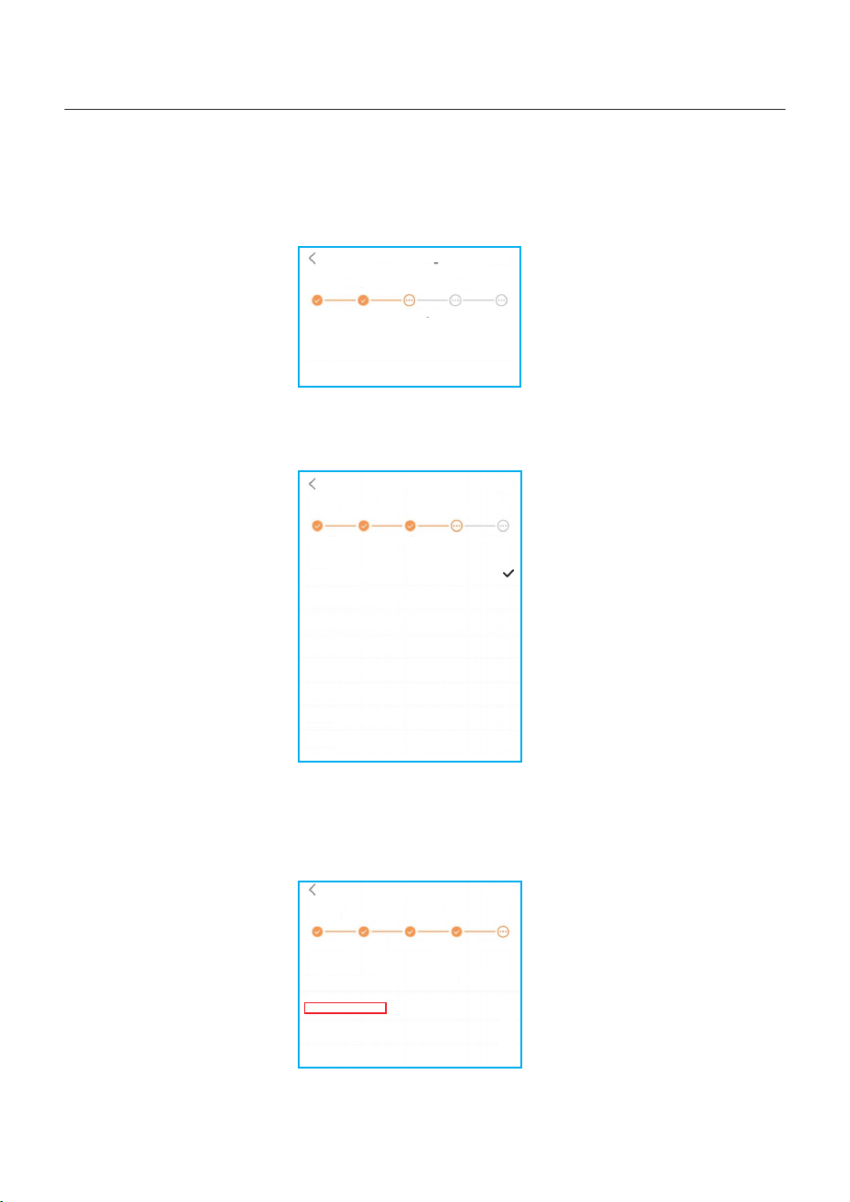
67
C. Meter Setting: Set both the Meter Type and the Meter Location. It is suggested to
install the meter at the system grid connection point and select “Meter in Grid”.If there
is no meter connected for the moment, please select”No Meter” to avoid alarms.
Quick Setting
Next
Inverter Time Meter Type Working Mode
Battery Model Grid Code
D. Grid Code: Please select the grid code based on the local grid network requirements.
Quick Setting
Next
Inverter Time
Battery Model Grid Code
G59/3
User-define
EN50549FI
BRA-N220
EN50549TR
SI-1
LTU-1
VDE 4105
5. Commissioning
User Manual
Meter/CT Setting
Meter Setting
Meter >
>
Meter Type Working Mode
E. Work Mode: This is the energy storage operating mode. ALL modes first priority is to
use the available PV power to support the home loads. The different modes determine
what the second priority, or use of the excess PV power, will be. Select the desired mode,
then tap the slider switch to turn the mode on. The switch will appear orange if it is enabled.
Quick Setting
Done
Inverter Time
Battery Model Grid Code
Current Work Mode
Self-Use Mode
Feed in Priority Mode
Off-grid Mode
>
>
>
Meter Type Working Mode
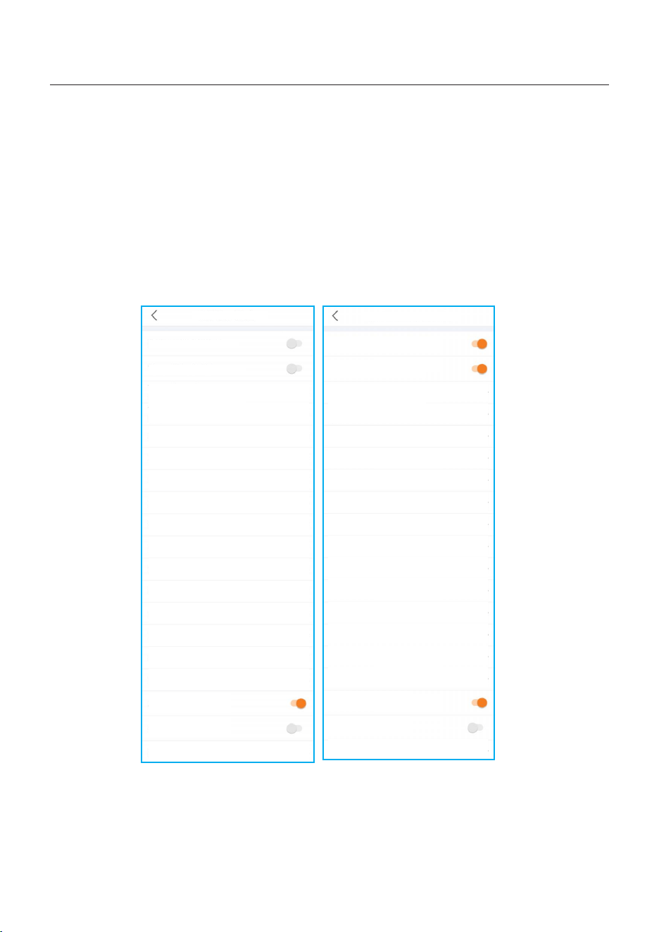
68
Self-Use Mode stores the excess PV power into the battery. If the battery is charged, or there
is no battery, the excess PV power will be exported(sold)back to the utility company. If the
system is set to not export any power, then the inverter will curtail the PV power(derate the
inverter output power).
5. Commissioning
User Manual
Feed in Priority Mode will ensure that the system exports any excess PV power after the
home loads are supplied. If the export power quota has been met, then the remaining PV
power will be stored in the battery. This mode should not be used if export power is going to
be set to zero.
Self-Use Mode Switch
Time of Use Switch
Time of Use Charge Current Set
50.0A >
Time of Use Discharge Current Set
50.0A >
Charge Time Slot 1
Discharge Time Slot 1
Charge Time Slot 2
Discharge Time Slot 2
22:00 ~ 08:00 >
08:00 ~ 22:00 >
00:00 ~ 00:00 >
00:00 ~ 00:00 >
Charge Time Slot 3
00:00 ~ 00:00 >
Discharge Time Slot 3
00:00 ~ 00:00 >
Charge Time Slot 4
00:00 ~ 00:00 >
Discharge Time Slot 4
00:00 ~ 00:00 >
Charge Time Slot 5
00:00 ~ 00:00 >
Discharge Time Slot 5
00:00 ~ 00:00 >
Charge Time Slot 6
00:00 ~ 00:00 >
Discharge Time Slot 6
00:00 ~ 00:00 >
Allow Grid Charging
Backup Mode Switch
Reserved SOC
80% >
Self-Use Mode
Feed in Priority Mode
Feed in Priority Mode Switch
Time of Use Switch
Time of Use Charge Current Set
135.0A >
Time of Use Discharge Current Set
Charge Time Slot 1
Discharge Time Slot 1
Charge Time Slot 2
Discharge Time Slot 2
00:00 ~ 01:00 >
01:00 ~ 02:00 >
02:00 ~ 04:00 >
04:00 ~ 06:00 >
Charge Time Slot 3
06:00 ~ 10:00 >
Discharge Time Slot 3
10:00 ~ 11:00 >
11:00 ~ 14:00 >
14:00 ~ 17:00 >
17:30 ~ 18:00 >
18:00 ~ 22:55 >
23:00 ~ 23:30 >
23:30 ~ 00:00 >
Allow Grid Charging
Backup Mode Switch
Reserved SOC
80% >
135.0A >
Charge Time Slot 4
Discharge Time Slot 4
Charge Time Slot 5
Discharge Time Slot 5
Charge Time Slot 6
Discharge Time Slot 6
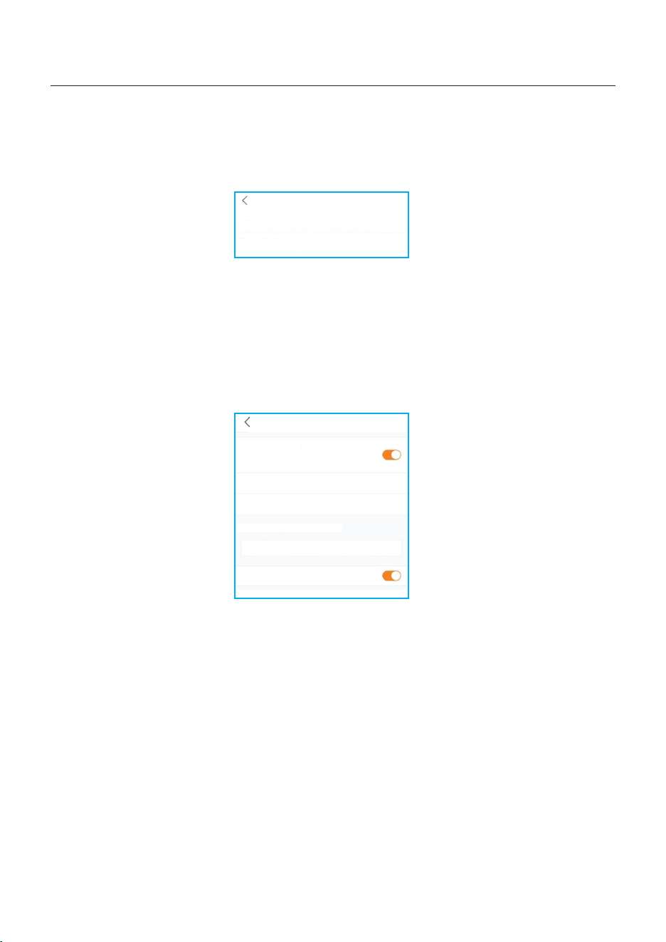
69
5. Commissioning
User Manual
Off-Grid Mode
Off-grid Mode Switch
Off-grid Overdischarge SOC
30%
>
Off-Grid Mode is only to be used by systems that are not electrically connected to the grid
at all. This mode is like Self-Use Mode, but the PV power will be curtailed if the battery is
charged and the home load demand is lower than the amount of available PV power.
Backup Mode can be opened in the Self-Use or Feed in Priority Mode. What this mode does
is ensure that the battery does not drain past the Reserve SOC(state-of-charge) percentage.
The battery will cycle between 100% and the Reserve SOC, so if grid power is lost, the battery
will have the Reserve SOC at the very least to carry the home through the outage.
Peak-shaving Mode: Peak-shaving function is possible to set the maximum power (Pmax)
that the system obtains from the main grid. The power of the main grid charges batteries and
supplies power to the load, which is within (Pmax). When the load power exceeds the set
maximum power (Pmax), the insufficient part is provided by the battery. At the same time,
users can set the Peak SOC and charge the battery to this SOC as far as possible under the
premise of satisfying Pmeter.
(Tips: Only the lithium battery with CAN connection support the peak-shaving mode)
Peak-shaving Mode
Peak-shaving Mode
Note: This mode only support the use with lithium
batteries with communication
Max.useable Grid Power
Baseline SOC
Charging & Discharging Setting
Allow Grid Charging
+ Add Time
70%
>
3000W
>
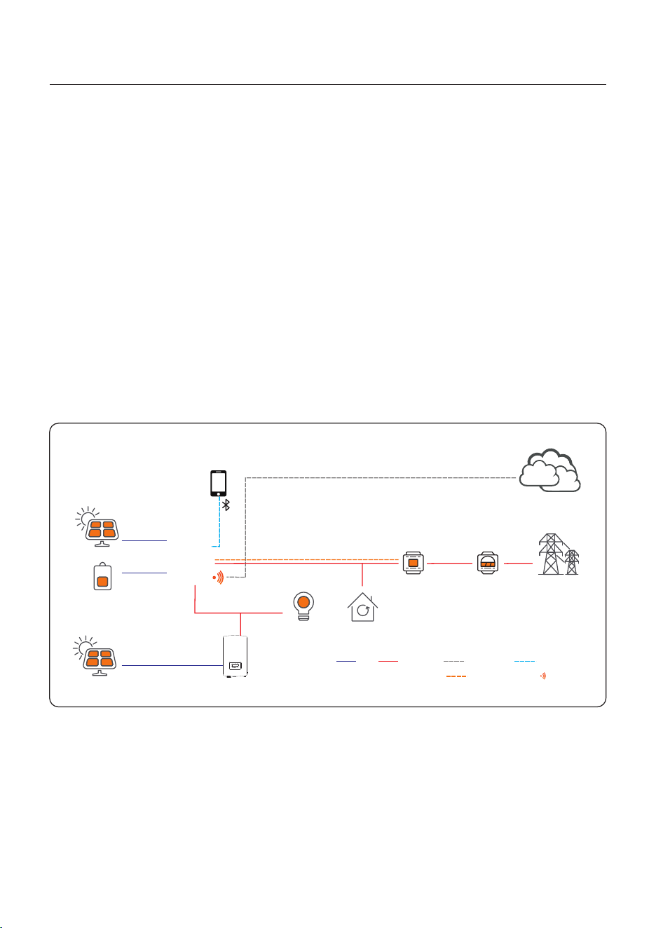
70
5. Commissioning
User Manual
AC Coupling Scheme
Customers can integrate a new energy storage inverter (S6 Hybrid) to an existed Grid - tied
inverter system. Users can select two ways of AC Coupling connection modes. One is connect
the Grid –tied inverter to S6 inverter Gen port and another is on the backup Port.
(Tips: When the total system is at on-grid status, the grid-tied PV inverter MUST be connected
to the backup port of hybrid inverter. )
Time of Use Switch is for customizing when the battery is allowed to charge and discharge
power and at what rate, established by a current(amperage)setting.If this slider switch is
turned on, the inverter will only use this schedule to determine when to charge and discharge
the battery. If Allow Grid Charging is turned on, the inverter will use grid power to charge the
battery only under two circumstances:(1) the battery drains to the Force Charge SOC.
(2)Time of Use is enabled and there is not enough available PV power during the charge
window to meet the current rate that is established.
Time of Use is for manual control of the battery charging/discharging.If Time of Use is
turned off, charging/discharging is automatically regulated by the inverter.
AC Coupling on Backup port
PV Strings
Battery
PV Strings
Grid
APP
Data Stick
Back-UP Load Loads
Power MeterSmart Meter
Soliscloud
Hybrid Inverter
PV Inverter
DC AC Internet Bluetooth
RS485 Communication Cable Communication
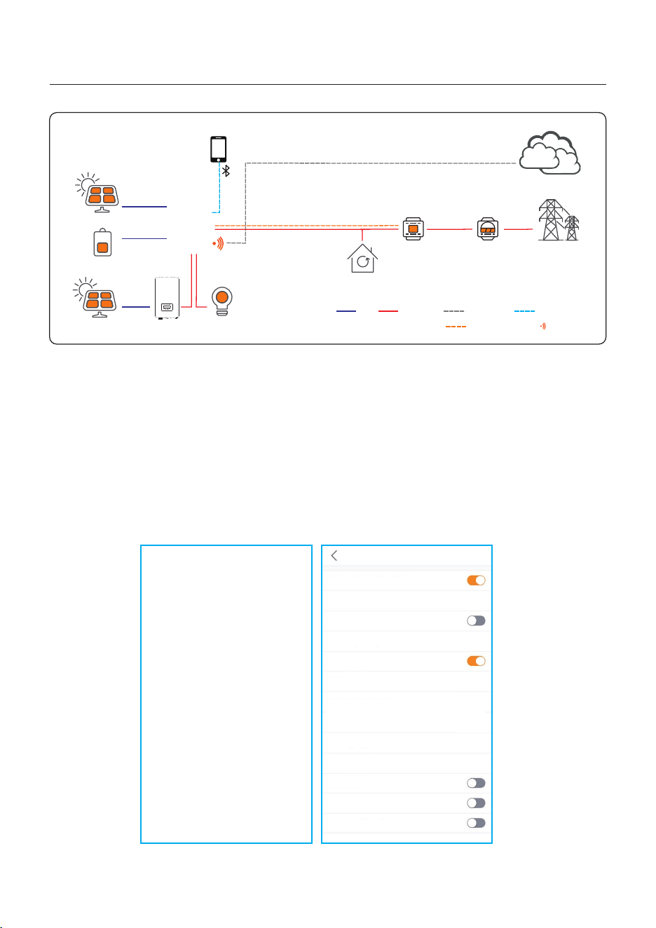
71
The settings about AC coupling under the smart port setting. When the AC Coupling switch
is turned on, customer should set the position is GEN port or Backup port. and set the
AC_Coupling _OFF_SOC and AC_Coupling _OFF_VOLT and AC_Coupling Max.fre.
AC_Coupling _OFF_SOC : When the lithium SOC rises to this set value, the grid-tied inverter
stops working through load reduction.
AC_Coupling _OFF_VOLT: When the lead acid Volt rises to this set value, the grid-tied inverter
stops working through load reduction.
AC_Coupling Max.fre: Default value 52Hz, when the system reaches the grid-tied inverter
shutdown condition, the system frequency changes to the set value and overfrequency load
reduction is carried out.
5. Commissioning
User Manual
For Lead-acid battery Type For Lithium Battery Type
AC Coupling on Gen port
Smart Port
Backup Port Enabling Setting
Backup Port Reference Voltage Setting
Voltage Droop Setting
Min.Droop Voltage
AC Coupling Switch
Position
AC Coupling_OFF_Bat_Volt
AC Coupling Max.fre
With Generator
Gen Port Load Open
Smart Load Switch
230.0V
>
180.0V
>
50.0V
>
51.60Hz
>
GEN Port
>
Backup Port Enabling Setting
Backup Port Reference Voltage Setting
Voltage Droop Setting
Min.Droop Voltage
AC Coupling Switch
Position
AC Coupling_ON_SOC
Start Frequency
With Generator
Gen Port Load Open
Smart Load Switch
AC Coupling_OFF_SOC
AC Coupling Max.fre
230.0V
>
180.0V
>
GEN Port
>
50%
>
60%
>
52.10Hz
>
50.00Hz
>
Smart Port
PV Strings
Battery
PV Strings
Grid
APP
Data Stick
Back-UP Load
Loads
Power MeterSmart Meter
Soliscloud
Hybrid Inverter
PV Inverter
DC AC Internet Bluetooth
RS485 Communication Cable Communication
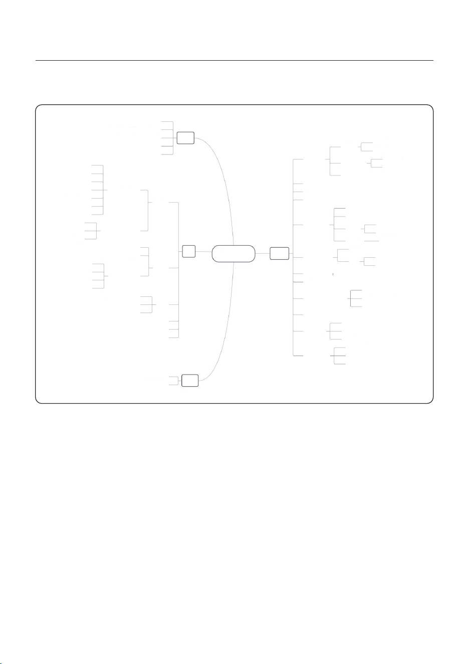
72
5.16.1 APP Interface Structure
5.16 APP Interface
5. Commissioning
User Manual
APP Inte rface
Info
Inverter
Battery
Grid
Load
GEN
Parallel
Basic Informati on
Advanced Inform at io n
SOC
Charging&Disc ha rg ing Energy
SOH
Battery Type
Voltage
Current
Other Parameter s
Energy Imported &E xp orted
Meter Data
Grid Data
Historical Alarm
Current Alarm
Alar m
Sett ing
Home
Voltage
Temperature
Power
Communication C on ne ction
Firmware Version
Model Number
Inverter Time
Grid Code
Inverter SN
PV Energy
GEN Energy
Today Consumption o f Lo ad
Today Yield of PV
Today Charge&Disc ha rg e of Battery
Today Imported&Em po rt ed of Grid
Work Mode
Tim e
Indicator
Grid Code
Battery Setting
Meter/CT Se tt ing
Grid Power Settin g
Backup Setting
Inverter Parame te r Se tting
Special Functio n
GEN Setting
Parallel Settin g
Self-Use
Feed in Priority
Off-Grid
Tim e of U se
Backup Mode
Tim e of U se
Backup Mode
Forcecharge
ECO Function
Lithium
Lead-acid
Protection
Battery Wake Up
Protection
Meter
CT
CT Reserv e
CT Ratio
Output Power Sett in g
Power Factor
Advanced Settin g of G ri d-tied Standard
GEN Power Setting
GEN Signal
GEN Force/Stop
Address ID
Phase Setting
Parallel Sync
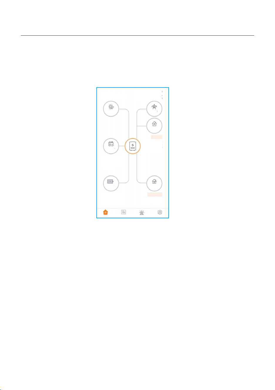
73
The home page can display the working state, Today Yield of PV, Today Imported/Exported of
Grid, Today Charged/Discharged of Battery ,Today Consumption of household electricity and
Today GEN yield. At the bottom of page are four submenus: Home, Info, Alarm and Settings.
5.16.2 Home
5. Commissioning
User Manual
Home
Info
Alarm
Settings
Today
Charged :0 .0KWh
Today
Dischar ge d:0.0KW h
Today Consumption
34.1KWh
Backup Side
Today GEN Yield:
0.0KWh
Today Consumption
0.0KWh
Grid Side
Today Yield:00.0KW h
Today imported:0. 0K Wh
Today
Exported:0.0K Wh
0W
0W
0.0W
0.0kW
0.0W
0W
74
The Info page breaks down into four categories: Inverter, Battery, Grid, and Load.
Inverter: inverter power production history, PV voltages and currents, inverter information
(serial number, model number, and firmware version),grid code, and alarm code history.
There are two additional information in the inverter page:
GEN Information: generator power, today and total generator yield, and warning information.
Parallel Information: information includes inverter, battery, grid and load.
Battery: battery model and status, battery voltage and current.
Grid: power imported an exported, AC grid voltage, frequency, and amperage.
Load: power being consumed by the home loads and backup loads.
Inverter
Battery
Grid
Load
Total Yield
221kWh
14.2kWh
191kWh
221kWh
Today Yie ld
This M onth Yield
This Yea r Yield
Yesterday Yield
12.8kWh
30kWh 0kWh
Last M onth Yield
Last Yea r Yield
View Histo rical Yield
>
Total PV Input Power
865W
Volta ge
Curr ent
Powe r
Pv1
Pv2
432. 6V
0.0V
2.0A
0.0A
865. 20W
0.00 W
Inverter SN
103115022B10 0041
Inverter Time
2022-12-2 3 15:32:03
Rated Power
6kW
Model Number
3115
DSP Firmware Version
V2
HMI Firmware Version
V1
HMI Firmware Subversion
Vd
Grid Code
G59/3
Communication Connection
Advanced Information
>
>
5.16.3 Information
Inverter
Battery
Grid
Load
49W
Discharge Power
99%
Battery SOC
Char ged
Disc harged
Today
Total
6.8k Wh
0.2k Wh
1830 kWh
1536 kWh
Other Parameters(From BMS)
Battery SOH
100%
Battery Model
Dyness LV
BMS Status
Normal
Battery Voltage BMS
50.28V
Battery Current BMS
0.0A
BMS Charge Current Limit
10.0A
BMS Discharge Current Limit
75.0A
Other Parameters(From inverter)
Battery Voltage
49.8V
Battery Current
1.0A
OverVoltage Protection Value
60.0V
UnderVoltage Protection Value
42.0V
Battery Equalization Voltage
53.5V
Inverter
Battery
Grid
Load
Expo rted Impo rted
Today
0.0k Wh
0.0k Wh
0.0k Wh
0.0k Wh
Yesterday
Total
1kWh
0kWh
Grid Data
Power
Voltage
Frequency
-1399W
220.8V
49.95Hz
Inverter
Battery
Grid
Load
Grid Side
Grid Load Power(Active)
0W
Total Grid Load Consumption
0kWh
Today Grid Load Consumption
0.0kWh
This Month Grid Load
Consumption
0kWh
0kWh
This Year Grid Load Consumption
Backup Side
Backup Load Power(Active)
2119W
Total Backup Load Consumption
1527kWh
Today Backup Load Consumption
34.2kWh
This Month Backup Load
Consumption
1202kWh
This Year Backup Load
Consumption
1527kWh
5. Commissioning
User Manual
75
The alarm page can display the current alarm and the historical alarm.
5.16.4 Alarm
<
<
Solis-3115022B100041
Solis-3115022B100041
Upda te :15:28:46
Upda te :15:28:46
Current Alarm
Historical Alarm
Alarm Message:
Alarm Code:
Alarm Grade:
Resolution Method:
HeartbeatLose
1065
EMGR
1.Check whether the
connection between the
parallel communication
wire is normal.
2. Restart the system and
confirm whether the fault
continues.
3. If it is not excluded,
please contact the
manufacturer’s customer
service.
Current Alarm
Historical Alarm
5. Commissioning
User Manual
Alarm Message:
Alarm Code:
Alarm Grade:
Resolution Method:
Alarm Time:
2023-04-01 16:27
HeartbeatLose
1065
EMGR
1.Check whether the
connection between the
parallel communication
wire is normal.
2. Restart the system and
confirm whether the fault
continues.
3. If it is not excluded,
please contact the
manufacturer’s customer
service.
The interface can display the current work mode, Self-Use/Feed in Priority/Off-Grid.
Mode Setting
5.16.5 Settings
Battery Setting
Battery Model: select the battery model to be connected.
Peak-shaving setting: If the switch is enable, the power of force charging will be
dynamically adjusted.
Few samples to be clear: (Forcecharge Limited Power Setting=4kW)
If the load=3kW,PV=0kW,P_forcecharge=P_Grid(4kW)-P_ Load(3kW)=1kW.
If the load=10kW,PV=0kW,P_forcecharge=0kW,P_Grid=P_Load=10kW.
ECO Function: If PV power is lower than 100W and SOC falls below overdischarge SOC,
the inverter will turn off the grid relays and IGBT switching. If forcecharge SOC is reached,
it will connect back to grid and charge battery back to overdischarge SOC, then turn off again.
Battery wake up: After Battery wake up command, the inverter powers the DC battery port
using Battery Wakeup Voltage and low AMP till BMS communication of battery will be restored
and within awaken time.
Over-discharge SOC: When the battery is discharged to the over-discharge soc, the battery
will nor discharge actively.(Due to the internal current, conduction, there is a small self-
consumption power, if not charged for a long time, the SOC will slowly continue to decline.)
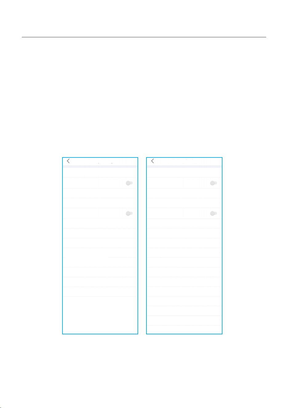
76
5. Commissioning
User Manual
Force-charge SOC: Due to the battery power consumption, when the over-discharge SOC
drops to the force-charge SOC, the inverter will directly charge the battery according to the
maximum battery charging current until the battery SOC reaches the over-discharge SOC.
(The charging power is nor limited to sources, which may be from PV or from the grid.
If “Charging from grid”is set to “Not Allow”,the charging logic may not be implemented.)
It is not recommended to set the over-discharge&force-charge SOC to the same value,
which may cause frequent charging and discharging.
GEN_Start_SOC/Volt: If SOC/Volt reaches GEN_Start_SOC/Volt, the generator can be
started.
GEN_Exit_SOC/Vot: If SOC/Volt reaches GEN_Exit_SOC/Volt, the generator can be
stopped.
Battery Setting
Time of Use Charge Current Set
50.0A >
Battery Model
PYLON_LV >
Peak-shaving Setting
Max. grid power when Forcecharging
500W >
Max. grid power when Forcecharging (Parallel)
0W >
ECO Function
Overdischarge SOC
20% >
Forcecharge SOC
10% >
Battery Overvoltage Protection Setting
60.0V >
Battery Undervoltage Protection Setting
42.0V >
GEN_Start_SOC
25% >
GEN_Exit_SOC
80% >
Battery Wake Up
>
Awaken Voltage
40.0V >
Awaken Time
20s >
Battery Setting
Time of Use Charge Current Set
50.0A >
Battery Model
Lead Acid >
Peak-shaving Setting
Max. grid power when Forcecharging
500W >
Max. grid power when Forcecharging (Parallel)
0W >
ECO Function
Battery Capacity
200Ah >
Max Charging Current
100.0A >
Battery Overvoltage Protection Setting
60.0V >
Battery Undervoltage Protection Setting
42.0V >
Overdischarge Voltage
44.5V >
Force Voltage
43.8V >
48.5V >
Max Discharging Current
100.0A >
GEN_Start_Volt
GEN_Exit_Volt
52.0V >
Equalization Voltage
56.4V >
Lead Acid TEMP CO
72mV/°C >
Environment temperature
Normal temper... >

77
5. Commissioning
User Manual
The Grid power charging limit function under the battery reservation condition
When battery is set at a reserved SOC by the Reserved SOC setting, the Power from grid to
charge battery is limited. If the Battery Peak shaving function is not enabled, user can also
set Max grid power when Force charging. In this case, the Force charging power is charged
according to the fixed value. The function can be enabled in Self-Use Mode and Feed in Priority
Mode.
For Self-Use Mode For Feed in Priority Mode
Self-Use Mode
Feed in Priority Mode
Self-Use Mode Switch
Charging & Discharging Setting
08 : 00 - 22 : 00 Charging
SOC1
Charge Current 1
22 : 00 - (Next Day)08 : 00 Discharging
SOC1
Discharge Current 1
Allow Grid Charging
Battery Reserve switch
Reserved SOC
Grid charging power limit
3000W
>
80%
>
90.0A
>
50%
>
90.0A
>
50%
>
+ Add Time
Feed in priority Mode Switch
Charging & Discharging Setting
08 : 00 - 22 : 00 Charging
SOC1
Charge Current 1
22 : 00 - (Next Day)08 : 00 Discharging
SOC1
Discharge Current 1
Allow Grid Charging
Battery Reserve switch
Reserved SOC
Grid charging power limit
3000W
>
80%
>
90.0A
>
50%
>
90.0A
>
50%
>
+ Add Time
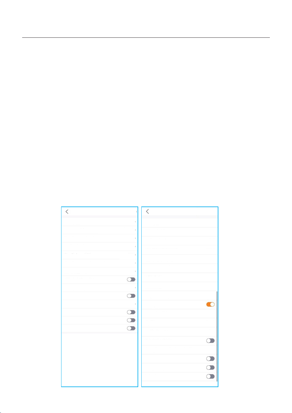
5. Commissioning
User Manual
Battery Discharge Hysteresis SOC
When the Force-charge SOC is reached, the battery will be force-charged to the Overdischarge
SOC + Overdischarge Hysteresis SOC. Overdischarge Hysteresis SOC range from 1% to 20%,
Overdischarge Hysteresis SOC default value is 1%.
For example: If customer set the Overdischarge SOC is 20%, Overdischarge Hysteresis SOC
is 5%.When the battery SOC is discharged to 10%( Forcecharge SOC set as 10%), Then the
lithium SOC will be forcecharged to 25%.
Battery Healing function
When the lithium battery is kept at low SOC for a long time, the measurement of lithium battery
SOC is not accurate. The Battery Healing function will allow the system to charge the battery to
the set Battery Healing SOC when the battery reaches the discharged SOC, so as to ensure the
healthy and stable operation of the lithium battery.
The Battery Equalization function of lead-acid battery
Pre-condition: When the days since last battery balancing exceed battery balancing Interval
days already set.Then the inverter will not enter the floating charge mode when the lead-acid
battery floating charge judgment is met for the first time on the same day when pre-condition
occur. But force charge battery at a balanced voltage on a constant voltage state, the charging
time is the time of balance, after finishing it, battery enter into float-charging state.
78
Battery Type
Battery Model
Max Charging Current
Max Discharging Current
Overdischarge SOC
Overdischarge Hysteresis SOC
Forcecharge SOC
Battery Healing Switch
Battery Healing SOC
Peak-shaving Setting
Max.grid power when Force charging
ECO Function
Battery Wakeup Switch
Auto Bat Awaken
Lithium Battery
>
Lithium Battery LV(RS485)
>
190.0A
>
190.0A
>
20%
>
1%
>
10%
>
100%
>
5000W
>
Battery Type
Battery Capacity
Max Charging Current
Max Discharging Current
Overdischarge Voltage
Forcecharge Voltage
Float Voltage
Temperature compensation coefficient
Battery Equalization
Equal Time
Equalized Interval
Peak-shaving Setting
Bulk Voltage
Equalization Voltage
Max.grid power when Force charging
ECO Function
Battery Wakeup Switch
Auto Bat Awaken
Lead-acid Battery
>
200Ah
>
50.0A
>
50.0A
>
44.5V
>
43.8V
>
57.6V
>
54.0V
>
0mV/°C
>
55.0V
>
180min
>
30day
>
1000W
>
Battery Setting
Battery Setting
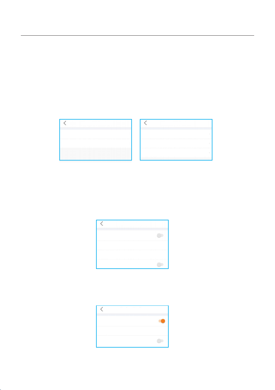
5. Commissioning
User Manual
Meter/CT Setting
You can select meter or CT for system measurement.
Meter Type: Please select a correct type. The wrong option may cause the meter RS485
communication Failed. If the battery and meter are not connected, please select the
“NO Meter” to shield the alarm of meter communication fault.
CT Reverse: If the direction is wrong, the sampling current of CT will be reversed when
calculating the power.
CT Ratio: CT ratio is adjustable.
Meter/CT Setting
Meter/CT Setting
Meter >
Meter Setting
>
Meter/CT Setting
Meter/CT Setting
CT >
CT Reverse
Forward >
CT Ratio
10 >
Grid Power Setting
System Export Power/Current: This is the amount of power/current the inverter is permitted
to export(or sell) back to the utility company. If you do not want the system exporting power,
this setting must be configured.
Failsafe Switch: Enabling the Failsafe switch will mean that the inverter will not produce any
P power if the inverter loses communication with the meter.
Grid Power Setting
System Export Power Limit Switch
System Export Power Limit Value
0W >
System Export Current Limit Value
0.0A >
Failsafe Switch
Backup Setting
Backup Voltage Setting: This is the voltage designated to the backup loads in the event of
a grid power loss.
Backup Setting
Backup Port Enabling Setting
Backup Port Reference Voltage Setting
230.0V >
Voltage Droop Setting
79
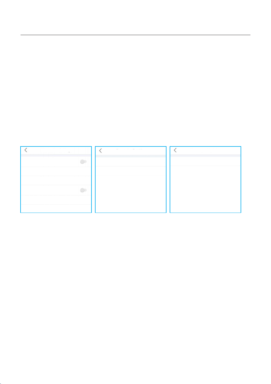
5. Commissioning
User Manual
Generator Setting
With Generator: Please turn it on if the generator is ready to work.
GEN Power Setting: GEN Rated Power/GEN Max.Charge Power.
Generator Position: Grid Port/GEN Port.
Grid Port Powered By: If the generator is connected in Grid Port and the generator works ,
please select “Generator”.
GEN Signal: If the generator can automatic start-stop,turn on the switch, once the generator
start condition is reached,the inverter will start the generator automatically.
GEN Force: If GEN_Start_SOC<SOC<GEN_Exit_SOC/GEN_Start_Volt<Volt<GEN_Exit_Volt,
the generator can be forced to start.
GEN Stop: If GEN_Start_SOC<SOC<GEN_Exit_SOC/GEN_Start_Volt<Volt<GEN_Exit_Volt,
the generator can be forced to stop.
Generator Setting
With Generator
GEN Power Setting
0W >
Generator Position
0.0A >
GEN signal
GEN Force
>
GEN Stop
>
Generator Setting
Generator Position
Grid Port >
Grid Port Powered By
Generator >
Generator Setting
Generator Position
Generator Port >
Grid Port Powered By
Generator >
80
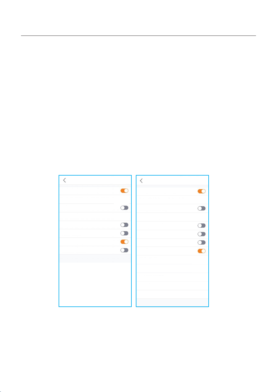
5. Commissioning
User Manual
The Second backup load and smart load
Second backup load: The GEN port can be set as the second Backup port(The setting name
on App: Gen Port Load Open), The Gen port has extended power, which can be used as a
second Backup port to pick up loads when the generator is not connected, thus expanding
backup capacity. In addition, in off-grid mode, the customer can remotely control, shut down
this port, so that some non-essential loads stop running, while keeping the necessary loads,
to achieve the purpose of energy saving.
Smart load: The smart load function means there is a load connected to GEN port can start
or stop smartly. When the PV energy and battery SOC/Volt meet the set value, the relay at the
generator port closes and outputs energy. When the PV energy is less than the set value or the
battery SOC/Volt drops to OFF SOC/Volt, the relay disconnects and stops supplying power to
the smart load.
Example: Set Start_Power=500W, Smart Load_ON_SOC=100%, Smart Load_OFF _SOC=95%.
When PV≥500W and SOC reaches 100%, Gen port supplies power to smart Load. If PV < 500W
or SOC≤95%, the relay is disconnected and power supply is stopped.
81
Smart Port
Backup Port Enabling Setting
Backup Port Reference Voltage Setting
Voltage Droop Setting
Min.Droop Voltage
AC Coupling Switch
230.0V
>
180.0V
>
With Generator
Gen Port Load Open
Smart Load Switch
Smart Port
Backup Port Enabling Setting
Backup Port Reference Voltage Setting
Voltage Droop Setting
Min.Droop Voltage
AC Coupling Switch
With Generator
GEN Port Load Open
Smart Load Switch
Min.Feed in Power
Load_ON_Batt SOC
Load_OFF_Batt SOC
Load_ON_Batt Volt
Load_OFF_Batt Volt
230.0V
>
180.0V
>
500W
>
90%
>
85%
>
55.0V
>
52.0V
>
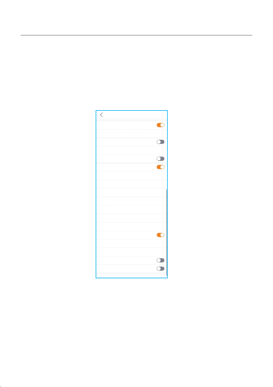
5. Commissioning
User Manual
The start and stop signal control of generator
The setting GEN Signal on App is used for control the automatic start or automatic stop of
generator .When the switch turned on, representing the generator possess the start and stop
automatically function.
When the switch turned off, representing the generator don’t have the start and stop
automatically function. Customer need to start or stop it manually by other settings.
(Tips: this function only can be used for the generator with external communication interface)
82
Backup Port Enabling Setting
Backup Port Reference Voltage Setting
Voltage Droop Setting
Min.Droop Voltage
AC Coupling Switch
With Generator
GEN Rated Power
Gen Max.Charge Power
Generator Position
GEN_Start_SOC
GEN_Exit_SOC
GEN Start Volt
GEN Exit Volt
GEN Signal
GEN Force
GEN Stop
GEN Port Load Open
Smart Load Switch
230.0V
>
180.0V
>
2.0kW
>
0.0kW
>
Grid port
>
20%
>
80%
>
46.0V
>
55.0V
>
Disable
>
Disable
>
Smart Port
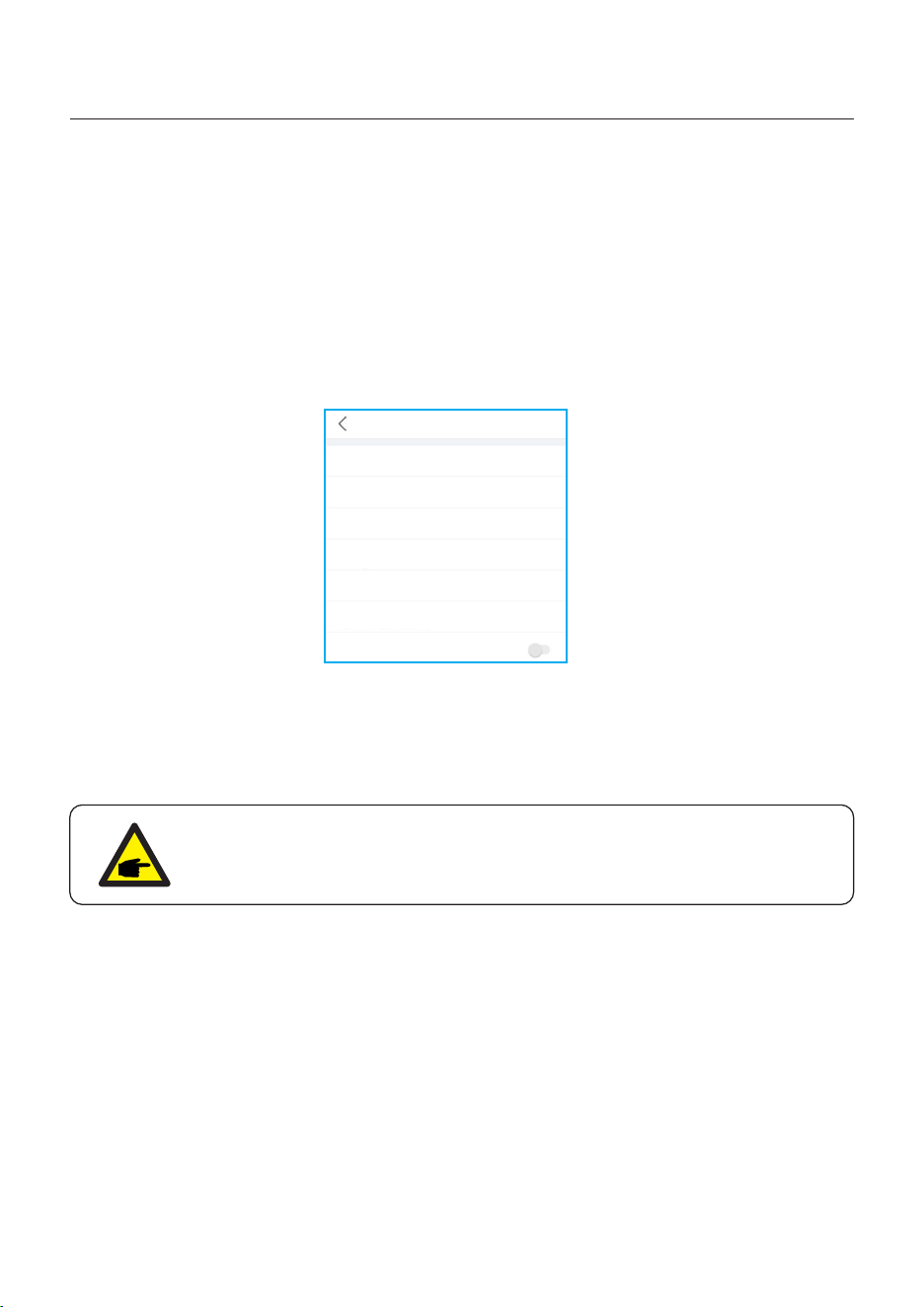
5. Commissioning
User Manual
Parallel Setting
Parallel Mode: Single/Parallel
Address ID: 1 to 6
Manual Set Master/Slave: Address ID 1 is Master, the others is Slave.
Inverter Connected Phase Setting: Single Phase(single phase system)/
Phase A(Three Phase)/Phase B(Three Phase)/Phase C(Three Phase)
Total number of hybrid inverters connected: 0-6
Parallel Sync: The parameters of the master will be synchronized to the slaves, and some
parameters of the slave cannot be set.
Parallel Setting
Parallel Mode
Single >
Address ID
2 >
Manual Set Master/Slave
Slave >
Inverter Connected Phase Setting
Single Ph... >
Battery Rated Energy Setting
3.0kWh >
Total number of hybrid inverters connected
2 >
Parallel Sync
The inverter commissioning process has now been completed. It is recommended to monitor
the system closely over the next week to ensure that everything is working as it should.
Please refer to the Solis data logger manual for assistance with registering a new plant on
SolisCloud.
NOTE:
A full factory reset can be done, if needed. This function can be found in the
Special Setting Function menu within the Settings tab.
83
NOTE:
Never use any solvents, abrasives, or corrosive materials to clean the inverter.
CAUTION:
Do not touch the surface when the inverter is operating. Some parts may be
hot and could cause burns. Turn OFF the inverter and let it cool down before
you do any maintenance or cleaning of inverter.
Solis S6 Series inverter does not require any regular maintenance. However, cleaning the
heatsink will help the inverter dissipate heat and increase the lifetime of inverter. The dirt on the
inverter can be cleaned with a soft brush.
The Screen and the LED status indicator lights can be cleaned with cloth if they are
too dirty to be read.
User Manual
6. Maintenance
6.1 Smart O&M
In order to improve our products and provide you with higher quality services, this device
has a built-in data logging module for collecting relevant information during operation
(such as power generation data, fault data)
Commitment:
1. We will only collect, use and process your device information for the purpose of
improving our products and services.
2. We will take all reasonable and feasible measures to ensure that no irrelevant
information is collected and we will protect your device information.
3. We will not share, transfer or disclose the collected device information with any
company, organization or individual.
4. When we stop operating products or services, we will stop collecting your device
information in a timely manner.
5. If you do not want to provide such information, you can notify our company to turn off
this function, which will not affect your normal use of other functions of the product.
84
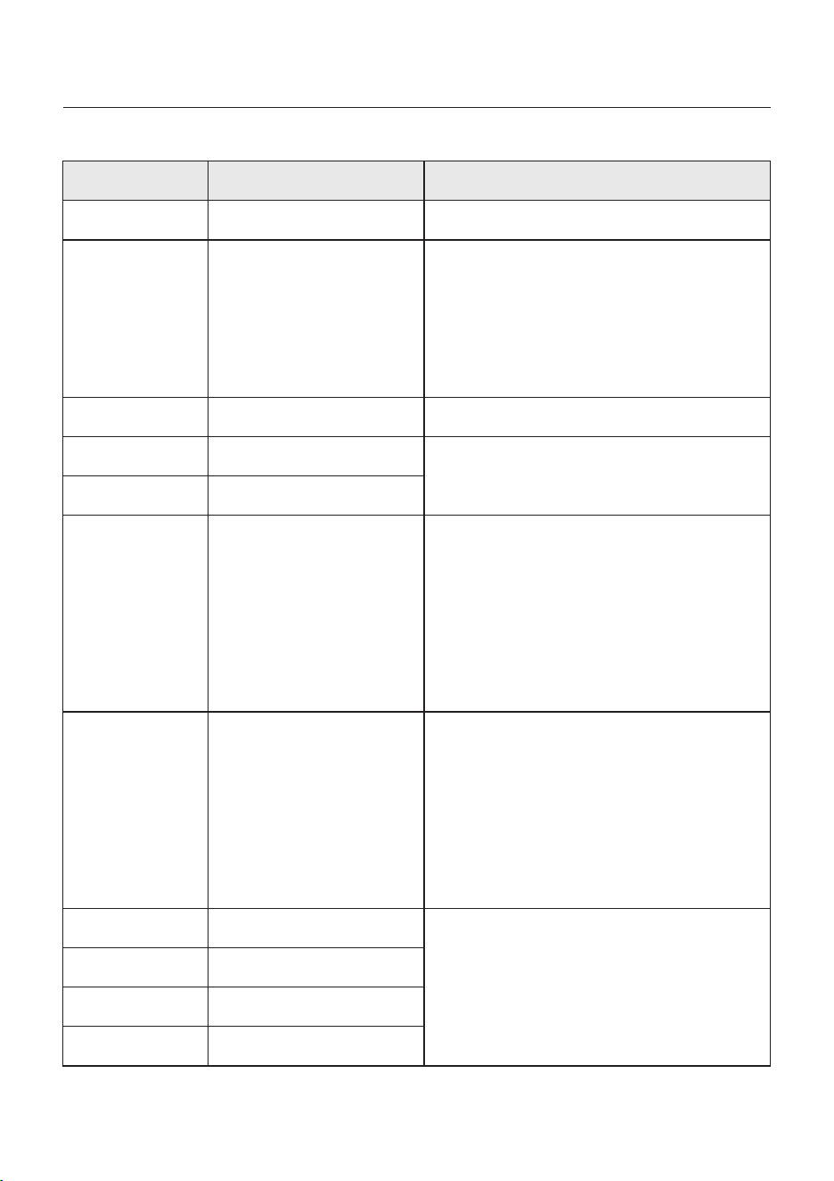
7. Troubleshooting
User Manual
Message Name
Information Description
Troubleshooting Suggestion
1. Confirm whether the inverter is connected
to an external EPM/meter to prevent
reverse current.
2. Confirm whether the inverter is controlled
by an external third-party device.
3. Confirm whether the power setting of the
inverter power control is limited.
4. Verify settings in section 6.6.7 and check
your meter readings.
1. No need to deal with it.
1. No need to deal with it, the device is in
normal operation.
1. Due to the requirements of local safety
regulations, when the grid voltage is high,
the Volt-watt working mode is triggered,
which generally does not need to be dealt with.
2. Inverter factory test errors causing this
mode to open, if you need to close, you can
close this mode in LCD, set the process:
Main menu → Advanced Settings →
Password 0010 → STD mode settings →
Working Mode → Working mode: NULL →
Save and exit.
LmtByEPM
LmtByDRM
LmtByTemp
LmtByFreq
LmtByVg
LmtByVar
The device's output is under
controlled
DRM Function ON
Over temperature power
limited
Frequency power limited
The device is in the
Volt-Watt mode
The device is in the Volt-Var
mode of operation
Off Control device to shutdown
1. Turn on the device in the ON/OFF Setting.
LmtByUnFr
Under frequency limit
Standby
Bypass run
StandbySynoch
Off grid status to On grid
status
1. No need to deal with it.
GridToLoad Grid to load
85
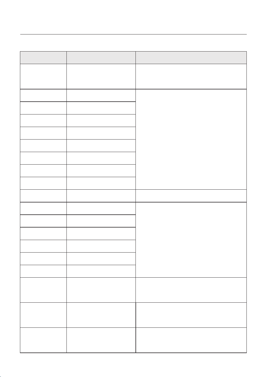
User Manual
OV-G-F01
UN-G-F01
G-PHAS E
G-F-GLU
NO-Grid
OV-G-V02
OV-G-V03
IGFO L-F
OV-G-V05
OV-G-V04
UN-G-V02
OV-G-F02
UN-G-F02
NO-Battery
Grid frequency exceeds the
upper frequency range
Grid frequency exceeds the
lower frequency range
Unbalanced grid voltage
Grid voltage frequency
fluctuation
Grid transient overvoltage
Grid transient overvoltage
Grid current tracking failure
Grid voltage RMS instanta-
neous overvoltage fault
Grid voltage exceeds the
upper voltage range
Grid voltage exceeds the
lower voltage range
Grid frequency exceeds the
upper frequency range
Grid frequency exceeds the
lower frequency range
Battery is not connected
UN-G-V01
Grid voltage exceeds the
lower voltage range
OV-G-V01
Grid voltage exceeds the
upper voltage range
Surge Alarm On-site grid surge
1. Grid side fault, restart the device.
If it is still not eliminated, please contact the
manufacturer's customer service.
1. Confirm whether the power grid is abnormal.
2. Confirm that the AC cable is properly
connected.
3. Restart the system and check if the fault
persists.
1. Restart the system, confirm if that the fault
continues.
1. Check on information page 1 – Verify the
battery voltage is within standards.
2. Measure battery voltage at plug.
No grid
1. Confirm whether the power grid is abnormal.
2. Confirm that the AC cable is properly
connected.
3. Restart the system and check if the fault
persists.
Message Name
Information Description
Troubleshooting Suggestion
OV-Vbackup
Over-Load
Inverting overvoltage
Load overload fault
1. Check whether the backup port wiring is
normal
2. Restart the system, confirm that the fault
continues.
1. Backup load power is too large, or some
inductive load startup power is too large,
need to remove some backup load, or remove
the inductive load on the backup.
7. Troubleshooting
86

User Manual
Message Name
Information Description
Troubleshooting Suggestion
BatName-FAIL
OV-Vbatt
UN-Vbatt
Fan Alarm
OV-DC01
(1020 DATA:0001)
OV-DC02
(1020 DATA:0002)
OV-BU S
(1021 DATA:0000)
UN-BUS01
(1023 DATA:0001)
UNB-BU S
(1022 DATA:0000)
UN-BUS02
(1023 DATA:0002)
DC-INT F.
(1027 DATA:0000)
OV-G-I
(1018 DATA:0000)
OV-DC A-I
(1025 DATA:0000)
OV-DC B-I
(1026 DATA:0000)
GRID-I N TF.
(1030 DATA:0000)
Wrong battery brand selection
Battery undervoltage detected
Fan alarm
DC 1 input overvoltage
DC 2 input overvoltage
DC bus overvoltage
DC bus undervoltage
DC bus unbalanced voltage
Abnormal detection of
DC bus voltage
DC hardware overcurrent
(1, 2, 3, 4)
A phase RMS value
overcurrent
DC 1 average overcurrent
DC 2 average overcurrent
AC hardware overcurrent
(abc phase)
Battery overvoltage detected
1. Confirm whether the battery model selection
is consistent with the actual one.
1. Restart the system and check if the fault
persists. If it is still not eliminated, please
contact the manufacturer's customer service.
1. Check if the internal fan is working correctly
or jammed.
1. Check if the PV voltage is abnormal
2. Restart the system, confirm that the fault
continues
1. Restart the system, confirm that the fault
continues.
1. Check if the DC wires are connected correctly
without loose connection.
1. Confirm that the grid is abnormal.
2. Confirm that the AC cable connection is not
abnormal.
3. Restart the system, confirm that the fault
continues.
1. Restart the system, confirm that the fault
continues.
1. Verify battery voltage is within standards.
Measure battery voltage at inverter connection
point. Contact your battery manufacturer for
further service.
CAN Fail CAN Fail
1. Can failure is a failure of communication
between inverter and battery. Check cable
conditions. Check to ensure you have it
plugged in on the CAN port of the battery and
inverter. Check that you are using the right
cable. Some batteries require a special
battery from the battery manufacturer.
7. Troubleshooting
87
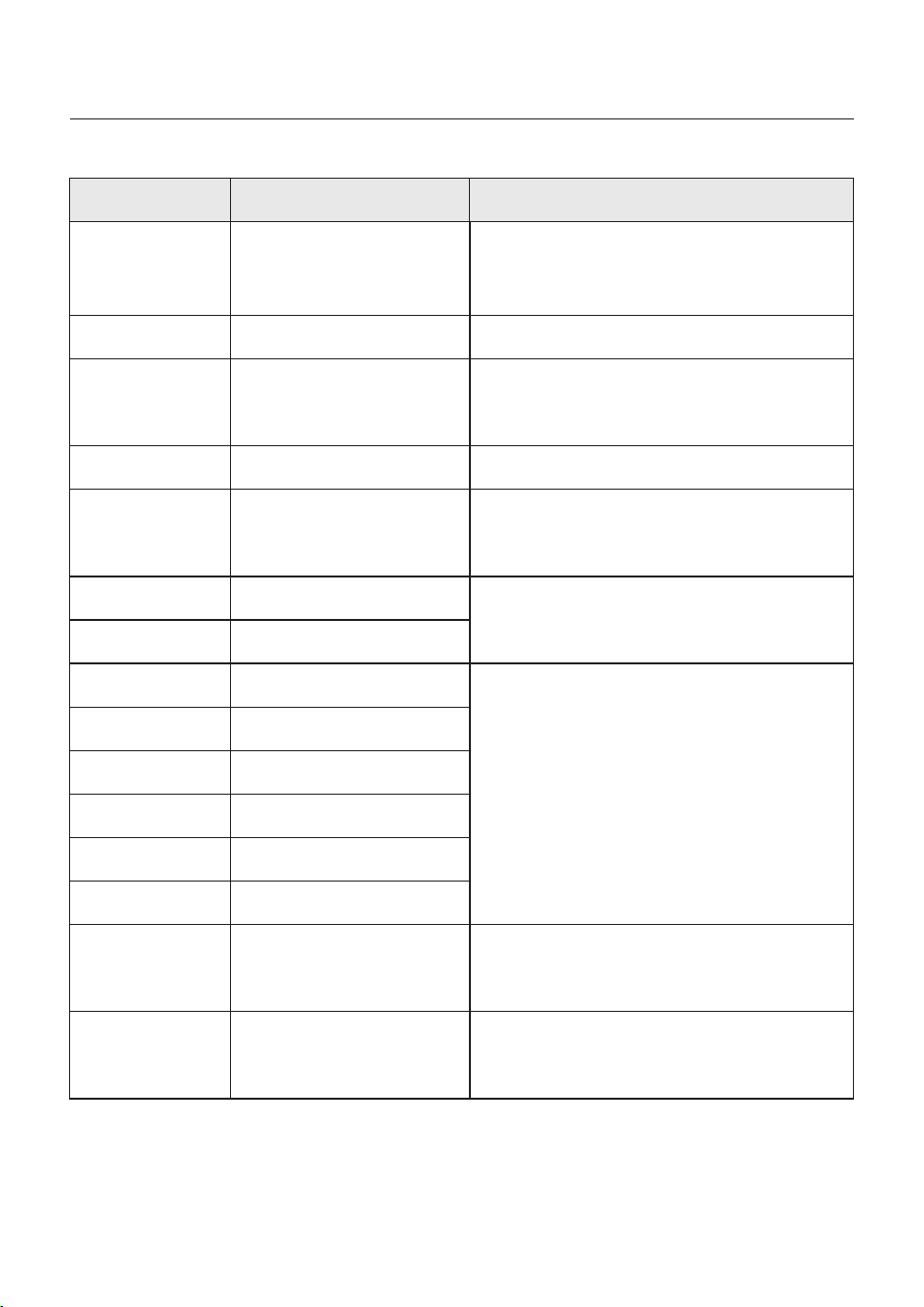
User Manual
Message Name
Information Description
Troubleshooting Suggestion
1. Confirm that the grid is abnormal.
2. Confirm that the AC cable connection is not
abnormal.
3. Restart the system, confirm that the fault
continues.
DCInj-FAU LT
(1037 DATA:0000)
The current DC component
exceeds the limit
IGBT-OV-I
(1048 DATA:0000)
OV-TE M
(1032 DATA:0000)
UN-TEM
(103A DATA:0000)
PV I SO-PRO01
(1033 DATA:0001)
PV I SO-PRO02
(1033 DATA:0002)
12Power-FAU LT
(1038 DATA:0000)
ILeak-PRO01
(1034 DATA:0001)
ILeak-PRO02
(1034 DATA:0002)
ILeak-PRO03
(1034 DATA:0003)
ILeak-PRO04
(1034 DATA:0004)
ILeak_Check
(1039 DATA:0000)
GRID-I N TF02
(1046 DATA:0000)
OV-Vbatt-H/
OV-BU S-H
(1051 DATA:0000)
IGBT overcurrent
Module over temperature
Low temperature protection
PV negative ground fault
PV positive ground fault
12V undervoltage failure
Leakage current failure 01
(30mA)
Leakage current failure 02
(60mA)
Leakage current failure 03
(150mA)
Leakage current failure 04
Leakage current sensor
failure
Power grid disturbance 02
Battery overvoltage hardware
failure / VBUS
1. Restart the system, confirm that the fault
continues.
1. Check whether the surrounding environment
of the inverter has poor heat dissipation.
2. Confirm whether the product installation
meets the requirements.
RelayChk-FAIL
(1035 DATA:0000)
Relay failure
1. Restart the system, confirm that the fault
continues.
1. Check the working environment temperature
of the inverter.
2. Restart the system to confirm if the fault
continues.
1. Check whether the PV strings have insulation
problems.
2. Check whether the PV cable is damaged.
1. Check current leakage to ground.
Verify your grounding.
Verify all wires are in good condition and not
leaking current to ground.
1. Confirm whether the grid is seriously distorted.
2. Check whether the AC cable is connected
reliably.
1. Check if the battery circuit breaker is tripping.
2. Check if the battery is damaged.
7. Troubleshooting
88
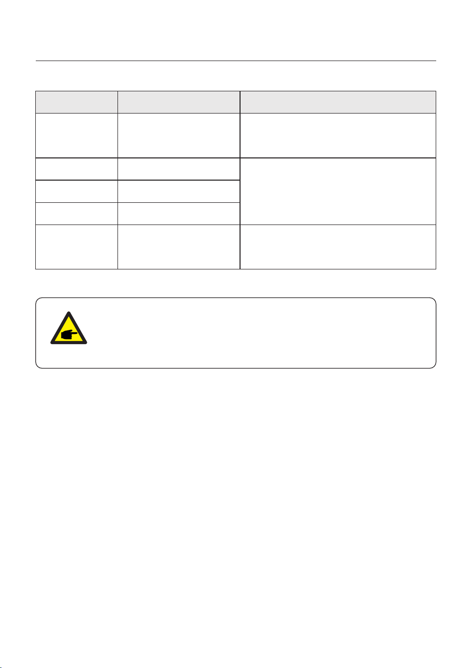
User Manual
OV-IL L C
(1052 DATA:0000)
LLC hardware overcurrent
1. Check whether the backup load is overloaded.
2. Restart the system, confirm that the fault
continues.
DSP-B-FAULT
(1036 DATA:0000)
AFCI-Check
(1040 DATA:0000)
ARC- FAULT
(1041 DATA:0000)
The master-slave DSP
communication is abnormal
AFCI self-test failure
AFCI failure
INI-FAULT
(1031 DATA:0000)
AD zero drift overlink
1. Restart the system, confirm that the fault
continues.
1. Verify connections are tight within your PV
system. Arc fault settings can be changed in
advanced settings if further adjustment is
necessary.
Table 7.1 Fault message and description
Message Name
Information Description
Troubleshooting Suggestion
NOTE:
If the inverter displays any alarm message as listed in Table 7.1; please
turn off the inverter and wait for 5 minutes before restarting it .
If the failure persists, please contact your local distributor or the service
center.
1. Serial number of Solis Singles Phase Inverter;
2. The distributor/dealer of Solis Singles Phase Inverter (if available);
3. Installation date.
4. The description of the problem together with necessary information, pictures,
attachment.
5. The PV array configuration (e.g. number of panels, capacity of panels, number of
strings, etc.);
6. Your contact details.
Please keep ready with you the following information before contacting us.
7. Troubleshooting
89
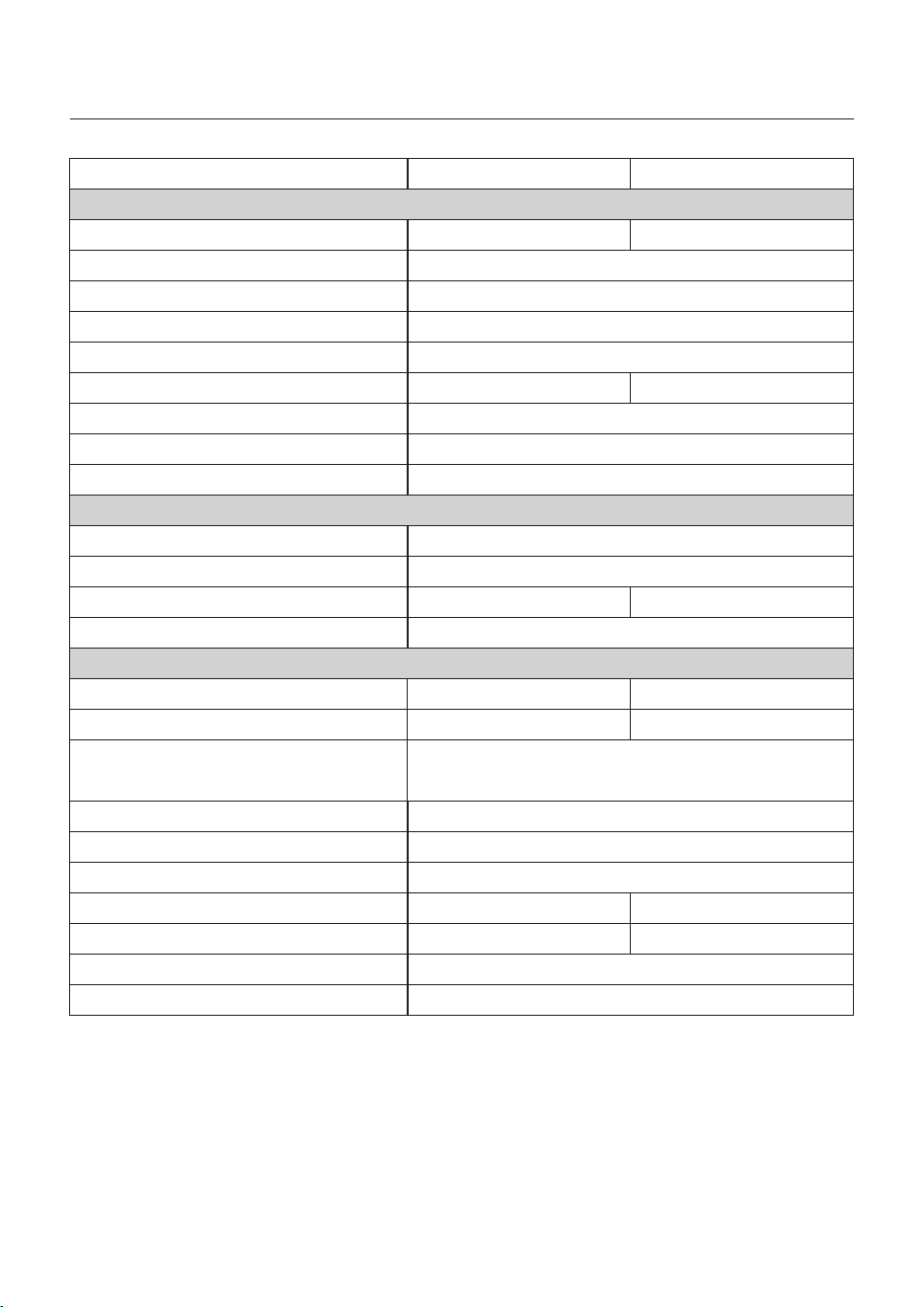
8. Specifications
User Manual
Max. input voltage
Start-up voltage
MPPT voltage range
MPPT number/Max input strings number
Max. input current
Battery Voltage range
Max Usable PV Input Power
Max. charge / discharge current
Communication
Technical Data
S6-EH3P8K02-NV-YD-L
160V
200-850V
2/3
20A/40A
180A
CAN/RS485
1000V
40-60V
Battery Type
Li-ion/Lead-acid
S6-EH3P10K02-NV-YD-L
Input DC (PV side)
Rated voltage
550V
Full load MPPT voltage range
213-850V
Max. short circuit current 30A/50A
Battery
220A
Rated output power
10kW8kW
Max. apparent output power
10kVA
8kVA
Output AC(Grid side)
Power Factor
>0.99 (0.8 leading - 0.8 lagging)
Max. output current
THDi
<3%
AC grid frequency range
Rated grid output current
12.2A/11.5A
45-55Hz/55-65Hz
15.2A/14.4A
The grid voltage range
Rated grid frequency
323-460V
50Hz/60Hz
Rated grid voltage
3/N/PE, 220V/380V
3/N/PE, 230V/400V
90
12.2A 15.2A
12.8kW 16kW
266-850V
Max. efficiency
EU efficiency
BAT charged by PV Max. efficiency
BAT charged/discharged to AC Max. efficiency
MPPT Effificiency
97.0%
95.0%/94.4%
94.5%
99.9%
Efficiency
97.5%
Technical Data
8. Specifications
User Manual
Rated output power
Max. apparent output power
Back-up switch time
Rated output voltage
Rated frequency
Rated output current
Max. Continuous output current
THDv(@linear load)
Max. allowable phase imbalance
Max. Continuous AC Passthrough current
8kW
2 times of rated power, 10 S
Output AC(Back-up)
Input AC (Grid side)
Input AC (Generator)
Max. input power
Input voltage range
Max. input current
Max. input power
Max. input current
Rated input frequency
Rated input frequency
12kW
323-460V
18.3A/17.3A
Rated input voltage
<10ms
10kW
12.2A/11.5A
12.2A
15.2A/14.4A
15.2A
91
50Hz/60Hz
10kW8kW
50 Hz/60 Hz
<3%
50%
50A
15kW
3/N/PE, 220V/380V
3/N/PE, 230V/400V
12.2A 15.2A
3/N/PE, 220V/380V
3/N/PE, 230V/400V
S6-EH3P8K02-NV-YD-L S6-EH3P10K02-NV-YD-L
45-55Hz/55-65Hz
22.8A/21.7A

Features
Display
Communication
Warranty
LCD + Bluetooth + APP
CAN, R S485, Ethernet, Optional:Wi-Fi, Cellular, LAN
5 years (Extend to 20 years)
AC connection
Screw terminal
Grid connection standard
NRS 097-2-1, IEC 62116, IEC 61727,
IEC 60068, I EC 61683, EN 50530, SriLanka,
EN 50438L,Vietnam, MEA, P EA
Safty/EMC standard
IEC/EN 62109-1/-2, IE C/EN 61000-6-1/-3
4000m
Max.operation altitude
MC4 Quick connection plug(PV)&
Screw terminal(Battery)
PV connnection
Dimensions(W/H/D)
430*660*305mm
-40℃~+60℃
Weight
Self consumption (Night)
Operation temperature range
General data
≤42KG
Non-isolated
Topology
IP66
<65 dB(A)
Smart Fan Cooling
Relative humidity
Ingress protection
Noise emission
Cooling concept
Technical Data
8. Specifications
User Manual
0-95%
92
<30W
Protection
Anti-islanding protection
Insulation Resistor detection
Output over current protection
Output short protection
Output over voltage protection
DC reverse polarity protection
DC surge protection/AC surge protection
Yes
Yes
Yes
Yes
Yes
Yes
S6-EH3P8K02-NV-YD-L S6-EH3P10K02-NV-YD-L
Yes
8. Specifications
User Manual
93
Max. input voltage
Start-up voltage
MPPT voltage range
MPPT number/Max input strings number
Max. input current
Battery Voltage range
Max Usable PV Input Power
Max. charge / discharge current
Communication
Technical Data
S6-EH3P12K02-NV-YD-L
160V
200-850V
2/3
20A/40A
250A
CAN/RS485
1000V
40-60V
Battery Type
S6-EH3P15K02-NV-YD-L
Input DC (PV side)
Rated voltage
550V
Full load MPPT voltage range
320-850V
Max. short circuit current 30A/50A
Battery
290A
Rated output power
15kW12kW
Max. apparent output power
15kVA
12kVA
Output AC(Grid side)
Power Factor
>0.99 (0.8 leading - 0.8 lagging)
Max. output current
THDi
<3%
AC grid frequency range
Rated grid output current
18.2A/17.3A
45-55Hz/55-65Hz
22.8A/21.7A
The grid voltage range
Rated grid frequency
323-460V
50Hz/60Hz
Rated grid voltage
3/N/PE, 220V/380V
3/N/PE, 230V/400V
18.2A 22.8A
19.2kW 24kW
300-850V
2/4
40A/40A
50A/50A
Li-ion/Lead-acid

8. Specifications
User Manual
94
Max. efficiency
EU efficiency
BAT charged by PV Max. efficiency
BAT charged/discharged to AC Max. efficiency
MPPT Effificiency
97.0%
95.0%/94.4%
94.5%
99.9%
Efficiency
97.5%
Technical Data
Rated output power
Max. apparent output power
Back-up switch time
Rated output voltage
Rated frequency
Rated output current
Max. Continuous output current
THDv(@linear load)
Max. allowable phase imbalance
Max. Continuous AC Passthrough current
12kW
2 times of rated power, 10 S
Output AC(Back-up)
Input AC (Grid side)
Input AC (Generator)
Max. input power
Input voltage range
Max. input power
Max. input power
Max. input current
Rated input frequency
Rated input frequency
18kW
323-460V
Rated input voltage
<10ms
15kW
18.2A/17.3A
18.2A
22.8A/21.7A
22.8A
50Hz/60Hz
15kW12kW
50 Hz/60 Hz
<3%
50%
50A
22.5kW
3/N/PE, 220V/380V
3/N/PE, 230V/400V
18.2A 22.8A
3/N/PE, 220V/380V
3/N/PE, 230V/400V
45-55Hz/55-65Hz
S6-EH3P12K02-NV-YD-L S6-EH3P15K02-NV-YD-L
27.3A/26.0A 34.2A/32.5A
8. Specifications
User Manual
95
4000m
Max.operation altitude
-40℃~+60℃
Weight
Self consumption (Night)
Operation temperature range
≤42KG
Non-isolated
Topology
IP66
<65 dB(A)
Smart Fan Cooling
Relative humidity
Ingress protection
Noise emission
Cooling concept
Technical Data
0-95%
<30W
Protection
Anti-islanding protection
Insulation Resistor detection
Output over current protection
Output short protection
Output over voltage protection
DC reverse polarity protection
Yes
Yes
Yes
Yes
Yes
Yes
S6-EH3P12K02-NV-YD-L S6-EH3P15K02-NV-YD-L
Dimensions(W/H/D)
430*660*305mm
General data
DC surge protection/AC surge protection
Yes
Features
Display
Communication
Warranty
LCD + Bluetooth + APP
CAN, R S485, Ethernet, Optional:Wi-Fi, Cellular, LAN
5 years (Extend to 20 years)
AC connection
Screw terminal
Grid connection standard
NRS 097-2-1, IEC 62116, IEC 61727,
IEC 60068, I EC 61683, EN 50530, SriLanka,
EN 50438L,Vietnam, MEA, P EA
Safty/EMC standard
IEC/EN 62109-1/-2, IE C/EN 61000-6-1/-3
MC4 Quick connection plug(PV)&
Screw terminal(Battery)
PV connnection
8. Specifications
User Manual
Max. input voltage
Start-up voltage
MPPT voltage range
MPPT number/Max input strings number
Max. input current
Battery Voltage range
Max Usable PV Input Power
Max. charge / discharge current
Communication
Technical Data
S6-EH3P7K02-LV-YD-L
160V
200-850V
2/3
20A/40A
156A
CAN/RS485
1000V
40-60V
Battery Type
Li-ion/Lead-acid
S6-EH3P8K02-LV-YD-L
Input DC (PV side)
Rated voltage
550V
Full load MPPT voltage range
225-850V
Max. short circuit current 30A/50A
Battery
178A
Rated output power
8kW7kW
Max. apparent output power
8kVA
7kVA
Output AC(Grid side)
Power Factor
>0.99 (0.8 leading - 0.8 lagging)
Max. output current
THDi
<3%
AC grid frequency range
Rated grid output current
18.4A/17.6A
45-55Hz/55-65Hz
21.0A/20.1A
The grid voltage range
Rated grid frequency
187-265V
50Hz/60Hz
Rated grid voltage
3/N/PE, 220V/230V
96
11.2kW 12.8kW
18.4A 21.0A
Max. efficiency
EU efficiency
BAT charged by PV Max. efficiency
BAT charged/discharged to AC Max. efficiency
MPPT Effificiency
97.0%
95.0%/94.4%
94.5%
99.9%
Efficiency
97.6%
Technical Data
8. Specifications
User Manual
Rated output power
Max. apparent output power
Back-up switch time
Rated frequency
Rated output current
Max. Continuous output current
THDv(@linear load)
Max. allowable phase imbalance
Max. Continuous AC Passthrough current
7kW
2 times of rated power, 10 S
Output AC(Back-up)
Input AC (Grid side)
Input AC (Generator)
Max. input power
Input voltage range
Max. input current
Max. input power
Max. input current
Rated input frequency
Rated input frequency
10.5kW
187-265V
27.6A/26.4A
Rated input voltage
<10ms
8kW
18.4A/17.6A
18.4A
21.0A/20.1A
21.0A
97
50Hz/60Hz
8kW7kW
50 Hz/60 Hz
<3%
50%
50A
12kW
3/N/PE, 220V/230V
18.4A 21.0A
45-55Hz/55-65Hz
31.5A/30.1A
S6-EH3P7K02-LV-YD-L S6-EH3P8K02-LV-YD-L
Rated input voltage
3/N/PE, 220V/230V
Features
Display
Communication
Warranty
LCD + Bluetooth + APP
CAN, R S485, Ethernet, Optional:Wi-Fi, Cellular, LAN
5 years (Extend to 20 years)
AC connection
Screw terminal
Grid connection standard
Philippin
Safty/EMC standard
IEC/EN 62109-1/-2, IE C/EN 61000-6-1/-3
4000m
Max.operation altitude
MC4 Quick connection plug(PV)&
Screw terminal(Battery)
PV connnection
Dimensions(W/H/D)
430*660*305mm
-40℃~+60℃
Weight
Self consumption (Night)
Operation temperature range
General data
≤42KG
Non-isolated
Topology
IP66
<65 dB(A)
Smart Fan Cooling
Relative humidity
Ingress protection
Noise emission
Cooling concept
Technical Data
8. Specifications
User Manual
0-95%
98
<30W
Protection
Anti-islanding protection
Insulation Resistor detection
Output over current protection
Output short protection
Output over voltage protection
DC reverse polarity protection
DC surge protection/AC surge protection
Yes
Yes
Yes
Yes
Yes
Yes
Yes
S6-EH3P7K02-LV-YD-L S6-EH3P8K02-LV-YD-L
8. Specifications
User Manual
Max. input voltage
Start-up voltage
MPPT voltage range
MPPT number/Max input strings number
Max. input current
Battery Voltage range
Max Usable PV Input Power
Max. charge / discharge current
Communication
Technical Data
S6-EH3P9K02-LV-YD-L
160V
200-850V
2/3
20A/40A
CAN/RS485
1000V
40-60V
Battery Type
Li-ion/Lead-acid
Input DC (PV side)
Rated voltage
550V
Full load MPPT voltage range
225-850V
Max. short circuit current 30A/50A
Battery
200A
Rated output power
9kW
Max. apparent output power
9kVA
Output AC(Grid side)
Power Factor
>0.99 (0.8 leading - 0.8 lagging)
Max. output current
THDi
<3%
AC grid frequency range
Rated grid output current
45-55Hz/55-65Hz
23.5A/22.6A
The grid voltage range
Rated grid frequency
187-265V
50Hz/60Hz
Rated grid voltage
3/N/PE, 220V/230V
99
14.4kW
23.5A
Max. efficiency
EU efficiency
BAT charged by PV Max. efficiency
BAT charged/discharged to AC Max. efficiency
MPPT Effificiency
97.0%
95.0%/94.4%
94.5%
99.9%
Efficiency
97.6%
Technical Data
8. Specifications
User Manual
Rated output power
Max. apparent output power
Back-up switch time
Rated frequency
Rated output current
Max. Continuous output current
THDv(@linear load)
Max. allowable phase imbalance
Max. Continuous AC Passthrough current
2 times of rated power, 10 S
Output AC(Back-up)
Input AC (Grid side)
Input AC (Generator)
Max. input power
Input voltage range
Max. input current
Max. input power
Max. input current
Rated input frequency
Rated input frequency
187-265V
Rated input voltage
<10ms
9kW
23.5A/22.6A
23.5A
100
50Hz/60Hz
9kW
50 Hz/60 Hz
<3%
50%
50A
13.5kW
3/N/PE, 220V/230V
23.5A
45-55Hz/55-65Hz
35.4A/33.9A
Rated input voltage
3/N/PE, 220V/230V
S6-EH3P9K02-LV-YD-L

Features
Display
Communication
Warranty
LCD + Bluetooth + APP
CAN, R S485, Ethernet, Optional:Wi-Fi, Cellular, LAN
5 years (Extend to 20 years)
AC connection
Screw terminal
Grid connection standard
Philippin
Safty/EMC standard
IEC/EN 62109-1/-2, IE C/EN 61000-6-1/-3
4000m
Max.operation altitude
MC4 Quick connection plug(PV)&
Screw terminal(Battery)
PV connnection
Dimensions(W/H/D)
430*660*305mm
-40℃~+60℃
Weight
Self consumption (Night)
Operation temperature range
General data
≤42KG
Non-isolated
Topology
IP66
<65 dB(A)
Smart Fan Cooling
Relative humidity
Ingress protection
Noise emission
Cooling concept
Technical Data
8. Specifications
User Manual
0-95%
<30W
Protection
Anti-islanding protection
Insulation Resistor detection
Output over current protection
Output short protection
Output over voltage protection
DC reverse polarity protection
DC surge protection/AC surge protection
Yes
Yes
Yes
Yes
Yes
Yes
Yes
S6-EH3P9K02-LV-YD-L
101

9. Appendix - FAQs
User Manual
Frequently Asked Questions
Q2: Why I have "BATName-Fail" Alarm on the inverter ?
A: Please check in the "Battery Setting->Battery Model" setting and confirm you selected the
correct battery option as the nameplate of your battery module.
Q3:Why I have "MET-SLT-Fail" Alarm on the inverter?
A: Please check in the "Meter Setting->Meter Type" setting and confirm you selected the
correct meter option corresponding to your smart meter.
Q4:Why the power values on the screen are fluctuating
very fast?
A: If your loads are changing drastically, the inverter will adjust its power accordingly. If you
confirm the loads are stable while the inverter power is changing very fast, please double
check your meter CT's direction and make sure the arrow is towards grid.
Q1: Why I have "CAN Fail" Alarm on the inverter?
A:"CAN Fail" indicates the CAN communication between inverter and battery is lost.
Please double check if your CAN cable is correctly connected and if your battery is power on.
Q5: Why I have "OV-ILLC" Alarm on the inverter ?
A: OV-ILLC indicates there is an overcurrent issue on the internal LLC circuit. It could be
transient status during extreme condition such as overload. If it happens constantly or too
frequent and the extreme conditions have been excluded, please contact Solis service team.
Q6: Why I have "OV-BATT-H" Alarm on the inverter ?
A: OV-BATT-H indicates over voltage issue on the hardware of battery circuit. It could be
caused by high battery voltage at full SOC, battery suddenly switching off, etc. If it happens
constantly or too frequent and the extreme conditions have been excluded, please contact
Solis service team.
Q7: Why I have "No-Battery" Alarm on the inverter?
A: Please double check if the battery power cables have been correctly connected and the
battery breaker (on battery or external) has been turn on. If you don't want to connect the
battery for now, please select the "No battery" option in "Battery Setting->Battery Model"
to prevent the alarm to show up.
102

Ginlong Technologies Co., Ltd.
No. 57 Jintong Road, Binhai Industrial Park, Xiangshan, Ningbo,
Zhejiang, 315712, P.R.China.
Tel: +86 (0)574 6578 1806
If you encounter any problem on the inverter, please find out the inverter S/N
and contact us, we will try to respond to your question ASAP.
Please adhere to the actual products in case of any discrepancies in this user manual.
Web: www.solisinverters.com