User Manual
for S6 Series Hybrid Inverter
Version 1.0, Release Date:10,2025
Applicable models
S6-EH3P60K10-LV-YD-H
S6-EH3P75K10-LV-YD-H
S6-EH3P80K10-NV-YD-H
S6-EH3P99.9K10-NV-YD-H
S6-EH3P100K10-NV-YD-H
S6-EH3P125K10-NV-YD-H
S6-EH3P75K10-NV-YD-H
Applicable System
Three phase system

Important Notes
Due to the product development,the product specifications and functions are subject to
change.The latest manual can be acquired via https://www.ginlong.com/global.
Every attempt has been made to make this document complete, accurate and up-to-date.
Individuals reviewing this document and installers or service personnel are cautioned,
however, that Solis reserves the right to make changes without notice and shall not be
responsible for any damages, including indirect, incidental or consequential damages
caused by reliance on the material presented including, but not limited to, omissions,
typographical errors, arithmetical errors or listing errors in the material provided in this
document.
Solis accepts no liability for customers' failure to comply with the instructions for
correct installation and will not be held responsible for upstream or downstream systems
Solis equipment has supplied.
The customer is fully liable for any modifications made to the system; therefore, any
hardware or software modification, manipulation, or alteration not expressly approved
by the manufacturer shall result in the immediate cancellation of the warranty.
Given the countless possible system configurations and installation environments, it is
essential to verify adherence to the following:
● There is sufficient space suitable for housing the equipment.
● Airborne noise produced depending on the environment.
● Potential flammability hazards.
● Solis will not be held liable for defects or malfunctions arising from:
● Improper use of the equipment.
● Deterioration resulting from transportation or particular environmental conditions.
● Performing maintenance incorrectly or not at all.
● Tampering or unsafe repairs.
● Use or installation by unqualified persons.
● This product contains lethal voltages and should be installed by qualified electrical
or service personnel having experience with lethal voltages.
Please notice: The system installed as required by Solis, the warranty is only effective for
Solis inverter, and other accessories are not guaranteed by Sols warranty.

01-07
08
41
11
13
14
20
21
08
01
02
41-42
16
25
1.1 Product Overview
………………………………………………………………………………………………………………………………
…………………………………………………………………………………………………………
…………………………………………………………………………………………………
……………………………………………………………………………………………
………………………………………………………………………………………………
…………………………………………………………………………………………………………………
………………………………………………………………………………………………………………………
………………………………………………………………………………………………………………
………………………………………………………………………………………………………………………………
…………………………………………………………………
…………………………………………………………………………………………………………………………………
1. Introduction
1.2 Inverter Wire Box and Connection Points
2. Safety & Warning
2.1 Safety
2.2 General Safety Instructions
4. Overview
4.1 Intelligent LED Indicators
3.8 CT Connection
3. Installation
3.1 Select a Location to Install the Inverter
3.2 Product Handling
3.5 PV Cable Installation
3.6 Battery Cable Installation
………………………………………………………………………………………………………………………………………
………………………………………………………………………
10
2.3 Notice for Use
10
………………………………………………………………………………………………………………
………………………………………………………………………………………………
………………………………………………………………………………………………
17
3.4 Ground Cable Installation
………………………………………………………………………………………………………
23
3.7 AC Wiring
…………………………………………………………………………………………………………………………
3.3 Mounting the Inverter
Contents
2.4 Notice for Disposal
11-40
………………………………………………………………………………………………………………………………
03
…………………………………………………………………………………………………………………
1.3 Product Features
1.4 Packaging
1.5 Tools Required for Installation
3.9 Inverter Communication
3.10 Diesel Generator Wiring
3.11 Parallel System Wiring
3.14 Inverter Remote Monitoring Connection
42
……………………………………………………………………………………………………………………
4.2 Password Reset
04
………………………………………………………………………………………………………………………………
40
………………………………………………………………
36
……………………………………………………………………………………………………
33
…………………………………………………………………………………………………
08-10
……………………………………………………………………………………………………………
04
………………………………………………………………………………………
42
…………………………………………………………………………
4.3 Inverter built-in Bluetooth description
………………………………………………………………………………………………………
37
3.13 Smart Meter measurement connection method for system
………………………………
39
10
……………………………………………………………………………………………………
2.5 Notice for Transporation
3.12 Lithium battery wiring
1.6 Lifting installation
05
……………………………………………………………………………………………………………………
1.7 Post mounting
07
……………………………………………………………………………………………………………………………

Contents
43
…………………………………………………………………………………………………………………………………
5. Commissioning
7. Troubleshooting
…………………………………………………………………………………………………………………
73
78
………………………………………………………………………………………………………………………
8. Specifications
43
5.1 Pre-Commissioning
………………………………………………………………………………………………………………………………
54
5.2 Power ON
……………………………………………………………………………………………………………………………
72
…………………………………………………………………………………………………………………………
6. Maintenance
72
6.1 Smart O&M
……………………………………………………………………………………………………………………………
5.3 Power OFF
5.5 APP Setting
43
……………………………………………………………………………………………………………
43-54
…………………………………………………………………………………………………………………
44
………………………………………………………………………………………………………………
5.4 HMI Screen Setting
90
………………………………………………………………………………………………………………
9. Appendix - FAQs
1. Introduction
User Manual
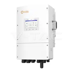
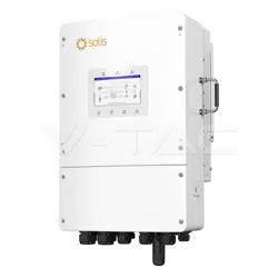
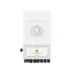
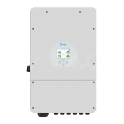
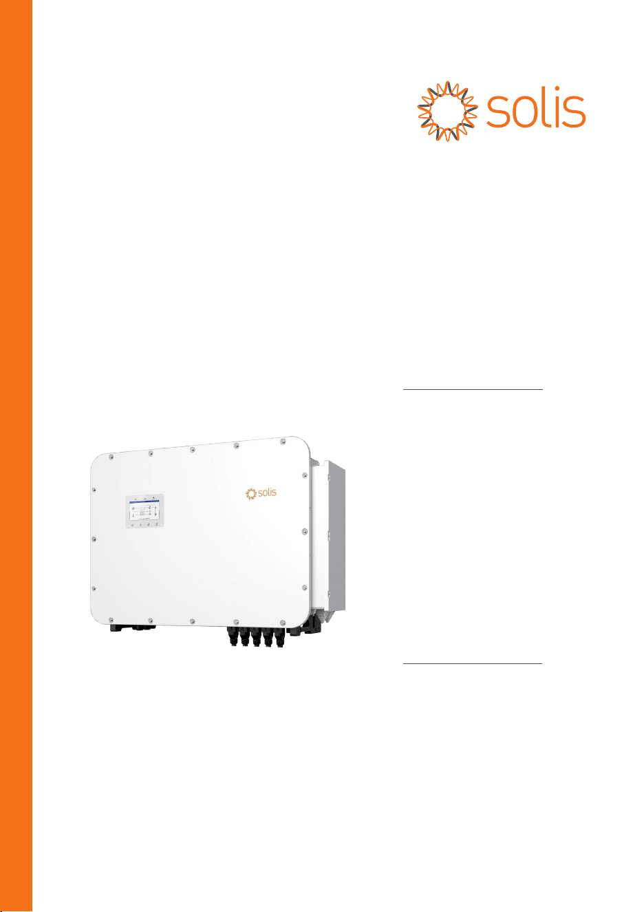
1.1 Product Overview
The Solis series is designed for commercial hybrid systems.
The inverter can work with maximize self-consumption and provide backup power if the grid
fails and there is not enough PV power to cover load demand.
The Solis S6 series consists of the following inverter models:
S6-EH3P60K10-LV-YD-H (Only available for LV grid)
S6-EH3P75K10-LV-YD-H (Only available for LV grid)
S6-EH3P80K10-NV-YD-H
S6-EH3P99.9K10-NV-YD-H (Only available for Vietnam, Thailand)
S6-EH3P100K10-NV-YD-H
S6-EH3P125K10-NV-YD-H
S6-EH3P75K10-NV-YD-H (Only available for Brazil)
Figure 1.1
Front side view
01
NOTE
Solis AFCI 2.0 Function meets the lNMETRO Ordinance No.515 regulation.
This product supports AFCl2.0 function as an optional funcition for
customers. By default the AFCl function is not supported.
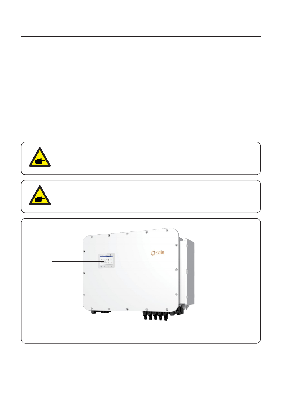
LCD Screen
NOTE
Only on Brazil and Chile market are sold with AFCI2.0 as default
configuration. If you want to use it, please refer to the manual to enable the
AFCl function.
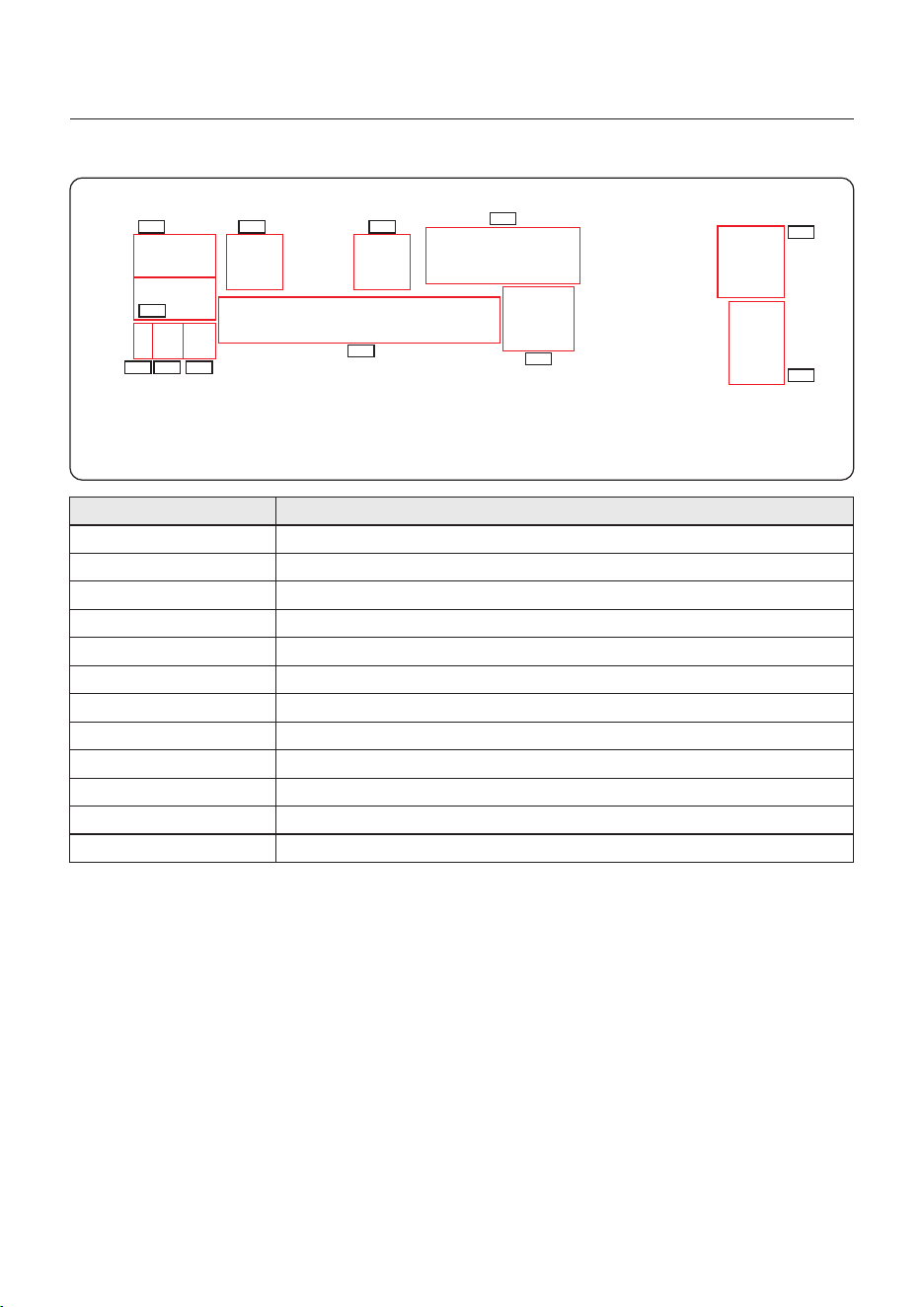
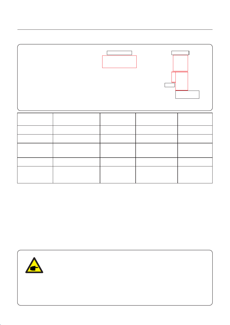
1.2 Inverter Wire Box and Connection Points
Name Description
3. PV Module Input
2. PV Switch2
4. COM1
1. PV Switch1
11. SMARTLOAD/GEN/INV
5. COM2
6. BACKUP
7. Battery Connection
9. COM
8. DATA
10. BlueTooth
12. Grid
For Solis data logger connection
For hybrid inverter communication signal enhancement, no need operation
A antenna for Bluetooth signal.no need operation
1. Introduction
User Manual
Conduit of PV conductors should be connected here
Communication cables of terminal block should go through this port
Communication cables of terminal block should go through this port
Conduit of AC conductors to backup loads panel should be connected here
Conduit of AC conductors to generator should be connected here
Conduit of AC conductors to the main service panel should be connected here
02
Conduit of Battery conductors should be connected here
11
12
1 2
3
4
5
6
7
9 108
PV switch of the PV1- Pv10
PV switch of the PV11- Pv20

User Manual
1.3 Product Features
Support dual batteries up to 100+100A/200A max charge/discharge current, flexible
battery configuration for customers on site.
Integrated 10 MPPTs and string current up to 21A, suitable for both 182mm and 210mm
PV modules.
Support 2 times rated power (on 75~100K model), 1.6 times rated power (on 125K model)
as peak power output on backup port to ensure crucial loads uninterrupted operation
during the switch of on and off grid, especially for air-conditioner, water pump, motor, etc.
Support 33.3% imbalance power of each phase on Backup port to ensure power supply for
different scenarios of loads.
Max. 10 pcs parallel for on-grid and off-grid operation, scalable capacity satisfying more
kinds of customer needs.
Compatible with batteries from multiple famous brands and support wide voltage range
giving customers multiple battery options.
Outstanding Performance
Support peak shaving control in both grid and generator condition.
Generator connectivity with multiple input methods and automatic generator On/Off control.
UPS level switching time (<10ms) supporting critical loads all the time.
99% High PV charge efficiency to prevent excess PV loss.
6 customizable charge/discharge time settings to gain more revenue from customer side.
Multiple working modes to meet different use case scenarios.
Controllable and Upgradeable via the SolisCloud App to avoid site visits.
Support Dual Battery connection, support battery connection with different brand and
different capacity under each inverter
Intelligent Function
Safe&Reliable
Safety protection with integrated AFCI function, which actively detects arc faults in the
PV side.
1. Introduction
03
Multiple battery protection function.
User Manual
Back plate x1
Fastening screw
(For Back plate) x8
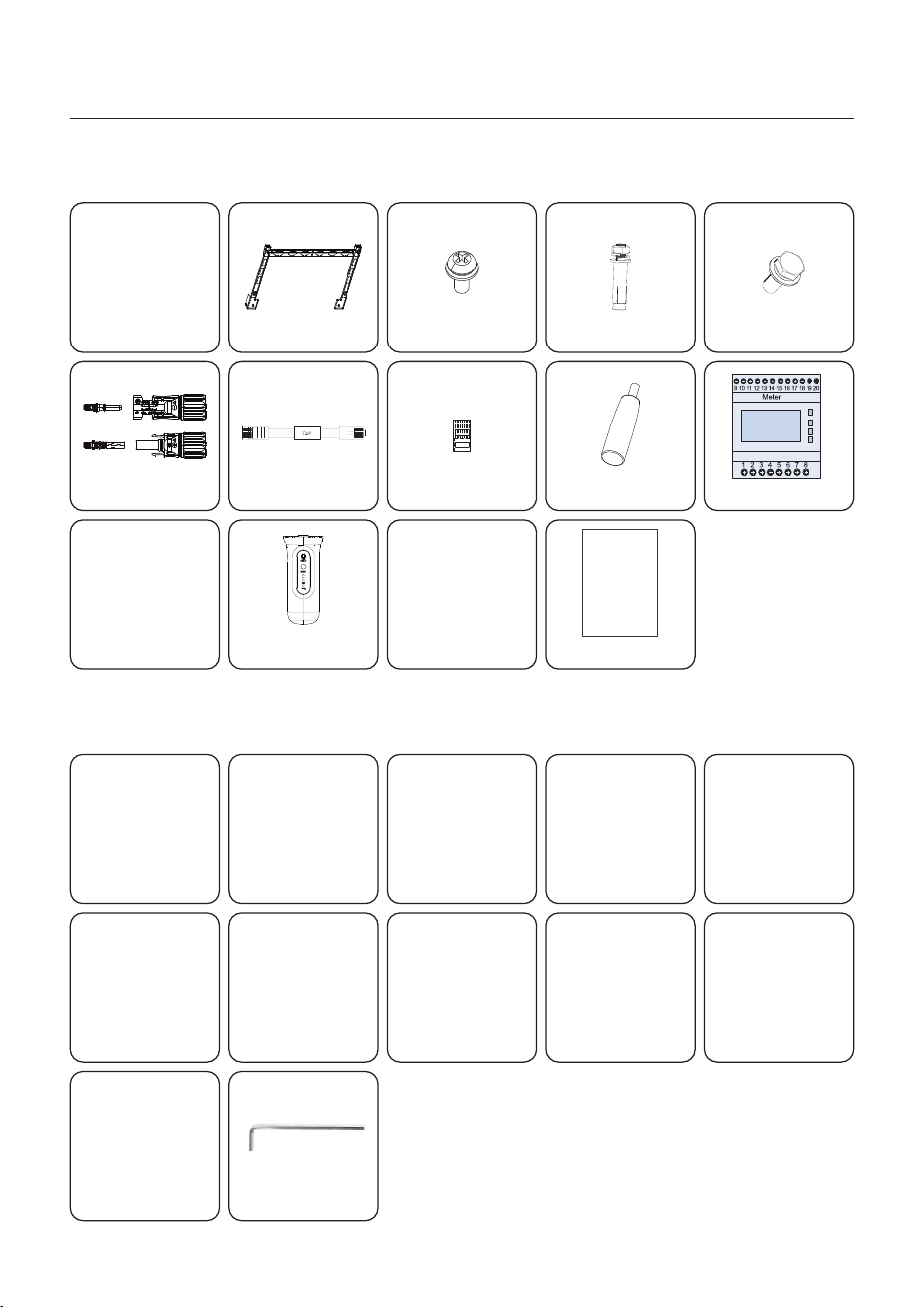
1.4 Packaging
Please ensure that the following items are included in the packaging with your machine:
If anything is missing, please contact your local Solis distributor.
Inverter x1
1. Introduction
DC connector x 20
04
Expansion Bolt x4
CAN cable(10m) x1
RJ45 connector x10
S2-WL-ST Data logger x1
Quick Installation Manual x1
Quick
Installation
Manual
Handle x4
1.5 Tools Required for Installation
Torqx T20 Screwdriver Wire Strippers 12AWG to 6AWG Wire Strippers 20AWG to 10AWG
Drill and Impact Driver
Multimeter (AC/DC amps)
Channel Locks
Technician Screwdriver
LUG Crimping Tool
Torque Screwdriver
MC4 Crimping Tool
CT 3x
Eastron Meter(optional) x1
Fastening screw x4
CT cables(5m) x6
hex key: 4mm
Socket/Bolt Wrench Tool

User Manual
1. Introduction
Installation Tools (The following tools are to be prepared by the customer)
1. Socket/Bolt Wrench Tool: Outer bolt specifications: M8, M10, M12;
2. Wrench Tool: Allen wrench and star-shaped Allen wrench set; Screw specifications: M6
3. Screwdriver Tool: Large and small cross and flat screwdrivers;
4. Torque Screwdriver: Torque screwdriver and a set of sockets (for wiring use, customers
can choose according to their needs);
5. Electric drill and impact drill and accessories;
Wiring Tools (The following tools and terminals must be prepared by the customer)
1. PV terminal MC4 crimping tool, Ethernet cable crimping tool;
2. Communication terminal crimping tool;
3. OT terminal crimping tool: for wire sizes of 25~95 square millimeters, matching terminals
are listed in the table below; wires and terminals need to be provided by the customer;
4. Accompanying wire stripping tools;
5. Accompanying heat shrink tubing and heat shrink tools;
3. Lifting tools (the following tools need to be provided by the customer)
M10 lifting ring *2,
500Kg lifting strap *2,
Lifting hook *2 - a set,
As shown in the image below;
Terminal type
Battery terminal Backup
Recommend copper cable diameter
Maximum support cable diameter
The size of the fixed bolts
Cable Lug
Torque
Smart load Grid PE
2
25-35mm
2
35mm
M6
25/35-6
4-5N.m
2
70mm
2
95mm
M8
70/95-8
10-12N.m
2
70mm
2
120mm
M12
70/90/120-12
20-30N.m
2
95mm
2
150mm
M12
95/120/150-12
20-30N.m
2
50-70mm
2
70mm
M10
50/70-10
10-12N.m
04
User Manual
1. Introduction
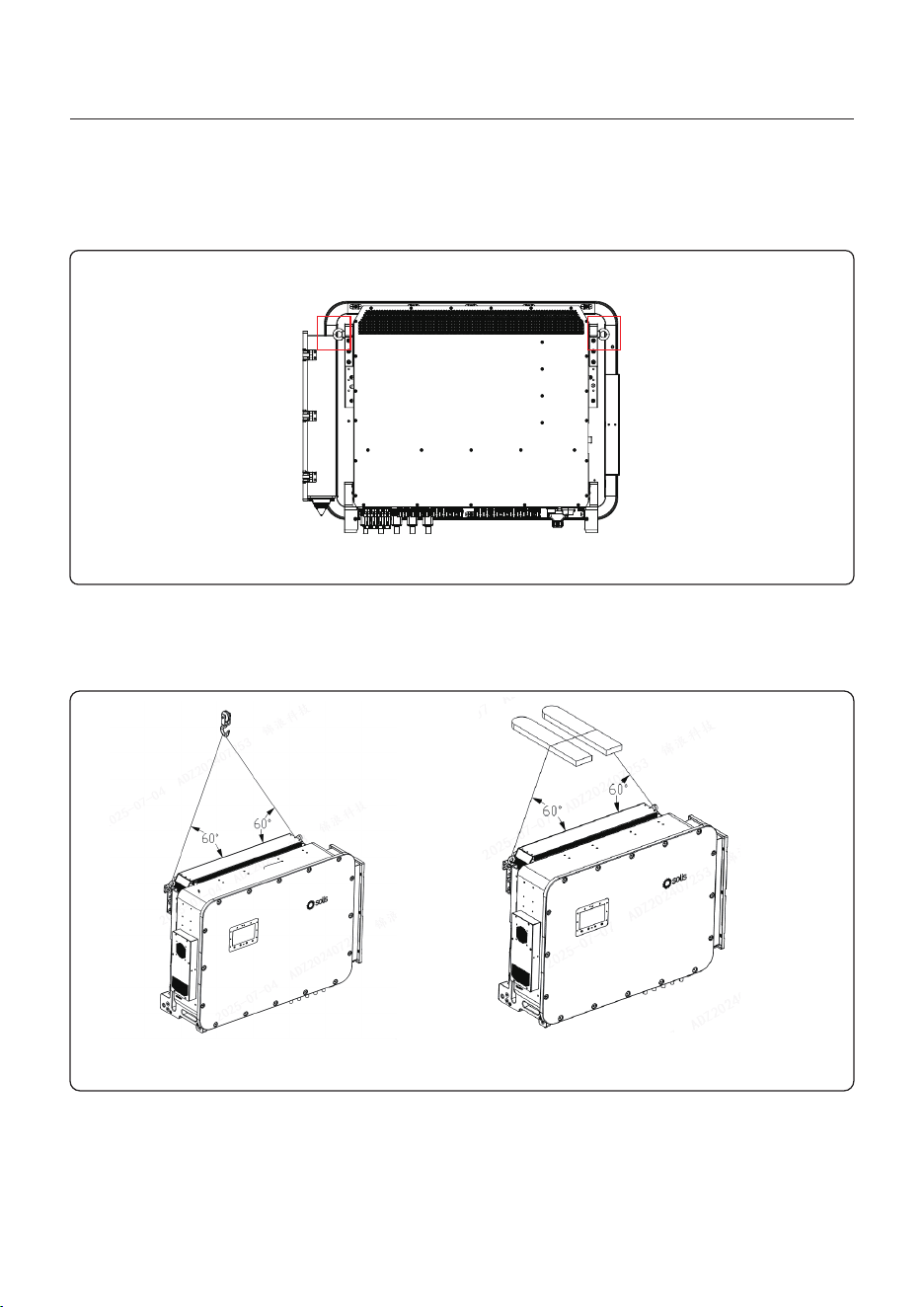
1.6 Lifting installation
There are two common types of lifting, as shown in the following figure. Users can adopt
different types of lifting according to specific circumstances. The specific usage requirements
are as follows
Lifting type 1 Lifting type 2
Description of lifting and installation process and recommended parameters of lifting equipment
Ear hanging size: M10(customer should configure the Ear hanging by themselves)
Lifting positions as shown in the red box in the following figure (a total of 2 locations)
05

User Manual
1. Introduction
Fixed lifting gear:
Symmetrically hang the lifting strap to the inverter lifting point and adjust the Angle by ≥60°
(as shown in the figure).
Test lift:
Slowly lift to 10cm above the ground, check the balance and equipment stability, stay for
1 minute without any abnormalities, and then continue.
Smooth movement:
Maintain a uniform lifting speed. Do not make sudden stops, swing or collide with
surrounding objects.
Positioning and installation:
After lowering to the installation base, first fix the bottom bracket, and then release the
lifting gear.
1.6.3 Lifting steps
1.6.2 Preparations before lifting
1.6.2.1 Equipment inspection
Confirm that the inverter housing is undamaged and that there are no cracks or deformations
at the lifting points (such as lifting lugs and brackets).
Check that the weight of the inverter matches the load of the lifting equipment (such as
forklifts, cranes) (it is recommended that the lifting capacity of the lifting equipment be twice
that of the inverter).
1.6.2.2 Selection of lifting gear
It is recommended to use nylon slings (or steel wire ropes) that are 5 to 7 times the weight
of the inverter.
The hook must be equipped with a safety lock to prevent it from coming off.
It is recommended to use lifting rings with a torque of 12-15N and a rated load of ≥200Kg.
Only professional lifting personnel are allowed to operate. Safety helmets, anti-slip
gloves and other protective equipment must be worn.
Before lifting, check that the lifting gear (wire ropes, slings, shackles, etc.) are free from
wear, rust or deformation.
Ensure that there are no unauthorized personnel in the operation area, and the ground is
flat and stable to avoid tilting or shaking.
Lifting is strictly prohibited during thunderstorms, strong winds (≥6th grade) or in damp
conditions.
1.6.1 Safety Warning
06
User Manual
1. Introduction
1.6.4 Lifting steps
Single-person operation is prohibited. At least two people are required to cooperate (one
person to direct, one person to operate the lifting equipment).
During the lifting process, it is strictly forbidden to grip the bottom of the equipment or stand
under the suspended object.
If any abnormal sounds, deviation or abnormality of the lifting equipment is detected,
immediately stop the operation and investigate the cause.
1.6.5 Emergency handling
Equipment tilts: Slowly descend to the ground and reposition the sling.
Hoist cable breaks: Evacuate personnel promptly and activate the backup hoist.
07
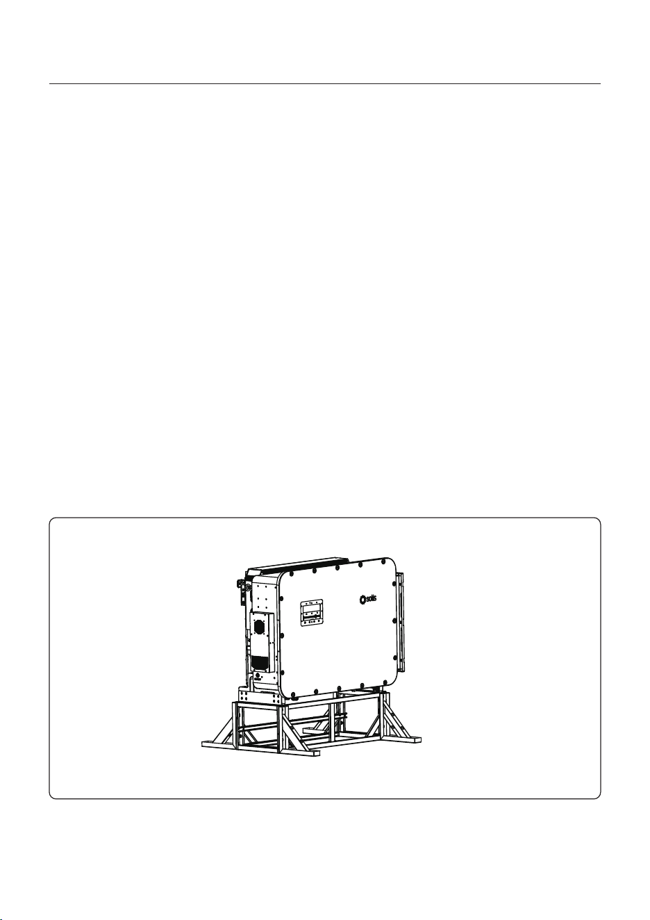
1.7 Post mounting
You can also use the post mounting method to install the inverter,
1. The on-site post need to be fixed to the ground through components.
2. When using post mounting, the minimum ground clearance at the bottom of the inverter
should be > 400mm.
3. Ensure that the surrounding environment meets the working environment requirements
of the inverter.
4. For other installation-related matters, please consult Solis technicians.
Here it’s the post mounting example schematic diagram.
2. Safety & Warning
User Manual
2.1 Safety
The following types of safety instructions and general information appear in this
document as described below:
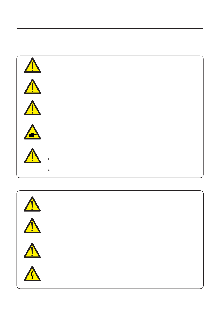
CAUTION
“Caution” indicates a hazardous situation which if not avoided, could result
in minor or moderate injury.
WARNING
“Warning” indicates a hazardous situation which if not avoided, could result
in death or serious injury.
DANGER
“Danger” indicates a hazardous situation which if not avoided, will result in
death or serious injury.
NOTE
“Note” provides tips that are valuable for the optimal operation of your
product.
2.2 General Safety Instructions
WARNING
Electrical installations must be done in accordance with local and national
electrical safety standards.
WARNING
Do not connect PV array positive (+) or negative (-) to ground, doing so could
cause serious damage to the inverter.
WARNING
Only devices in compliance with SELV (EN 69050) may be connected to the
RS485 and USB interfaces.
WARNING
Do not touch any internal parts until 5 minutes after disconnection
from the utility grid, PV array, and battery.
WARNING: Risk of fire
Despite careful construction, electrical devices can cause fires.
Do not install the inverter in an area containing flammable materials
or gases.
Do not install the inverter in a potentially explosive atmosphere.
08
2. Safety & Warning
User Manual
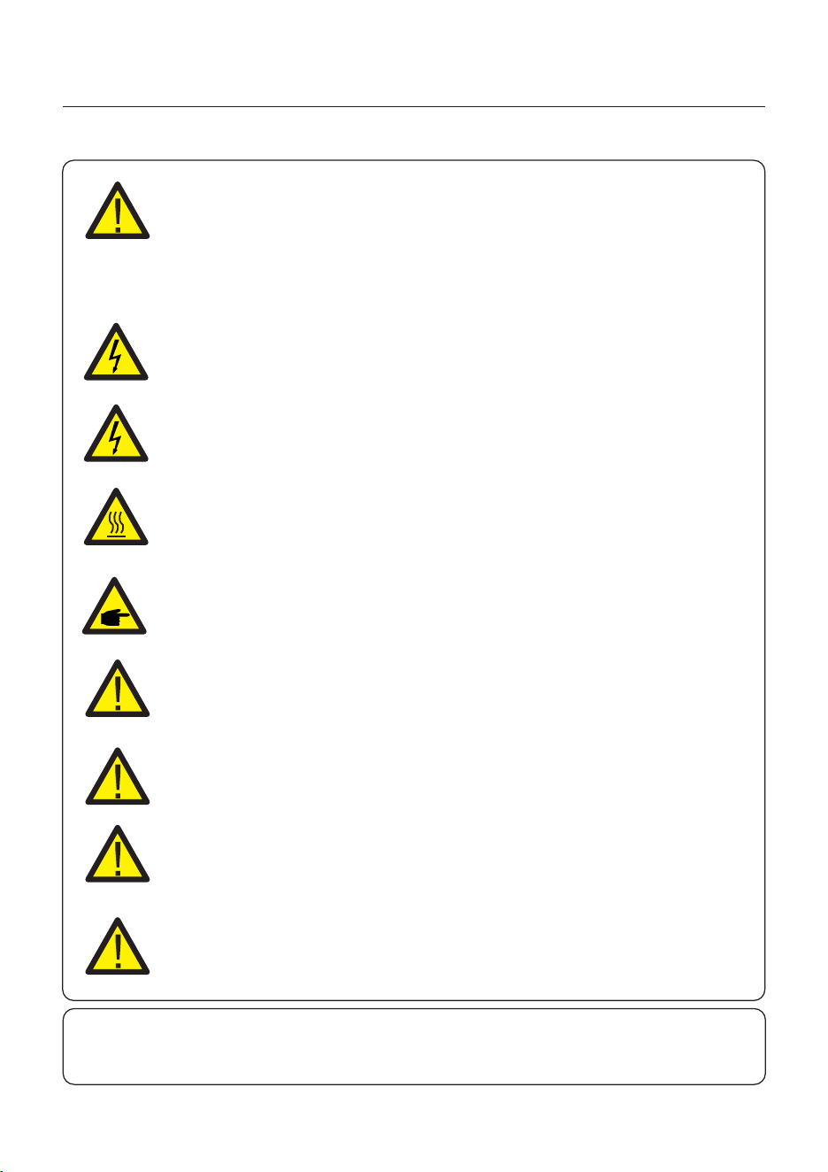
CAUTION
The PV conductors are energized with high voltage DC when the PV
modules are exposed to sunlight.
CAUTION
The surface temperature of the inverter can reach up to 75℃ .
To avoid risk of burns, do not touch the surface of the inverter while it is
operating. The inverter must be installed out of direct sunlight exposure.
WARNING
To reduce the risk of fire, over-current protective devices (OCPD) are
required for all circuits connected to the inverter.
The DC OCPD shall be installed per local requirements. All photovoltaic
source and output circuit conductors shall have isolators that comply with
the NEC Article 690, Part II.
All Solis single phase inverters feature an integrated DC disconnect switch.
CAUTION
Risk of electric shock, do not remove the cover. There are no serviceable
parts inside, refer servicing to qualified and accredited service technicians.
NOTE
PV modules used with inverter must have an I EC 61730 Class A rating.
WARNING
Operations must be accomplished by a licensed electrician or a
person authorized by Solis.
WARNING
Installer must wear personal protective equipment during the
entire installation process in case of electrical hazards.
WARNING
The AC Backup Port of the inverter cannot be connected to the grid.
WARNING
Please refer to the product manual of the battery before installation
and configuration to the inverter.
Systems using this product shall be designed and built in
accordance with the NEC & local electrical codes & standards.
09

2. Safety & Warning
User Manual
10
2.3 Notice for Use
The inverter has been constructed according to the applicable safety and technical
guidelines, use the inverter in installations that meet the following specifications only:
1. Permanent installation is required.
2. The electrical installation must be compliant with all local and national regulations &
standards.
3. The inverter must be installed according to the instructions stated in this manual.
4. The inverter must be installed according to the inverter technical specifications.
2.4 Notice for Disposal
This product shall not be disposed as household waste.
It must be segregated and brought to an appropriate disposal facility
to ensure proper recycling.
This is to be done in order to avoid negative impacts on the environment
and human health.
Local waste management rules shall be observed and respected.
2.5 Notice for Transporation
For the transportation demands of integrating with battery or install inverter in container,
solis only support separate transport, and the battery pack should be placed in the freight
cabinet follow the battery manufacturer's rule, and the inverter should be placed on its
own tray, we also dont support the machine is transported in the cabinet in the form of
back-hanging.
User Manual
WARNING: Risk of fire
Despite careful construction, electrical devices can cause fires.
Do not install the inverter in areas containing highly flammable materials
or gases.
Do not install the inverter in potentially explosive atmospheres.
The mounting structure where the inverter is installed must be fireproof.
3. Installation
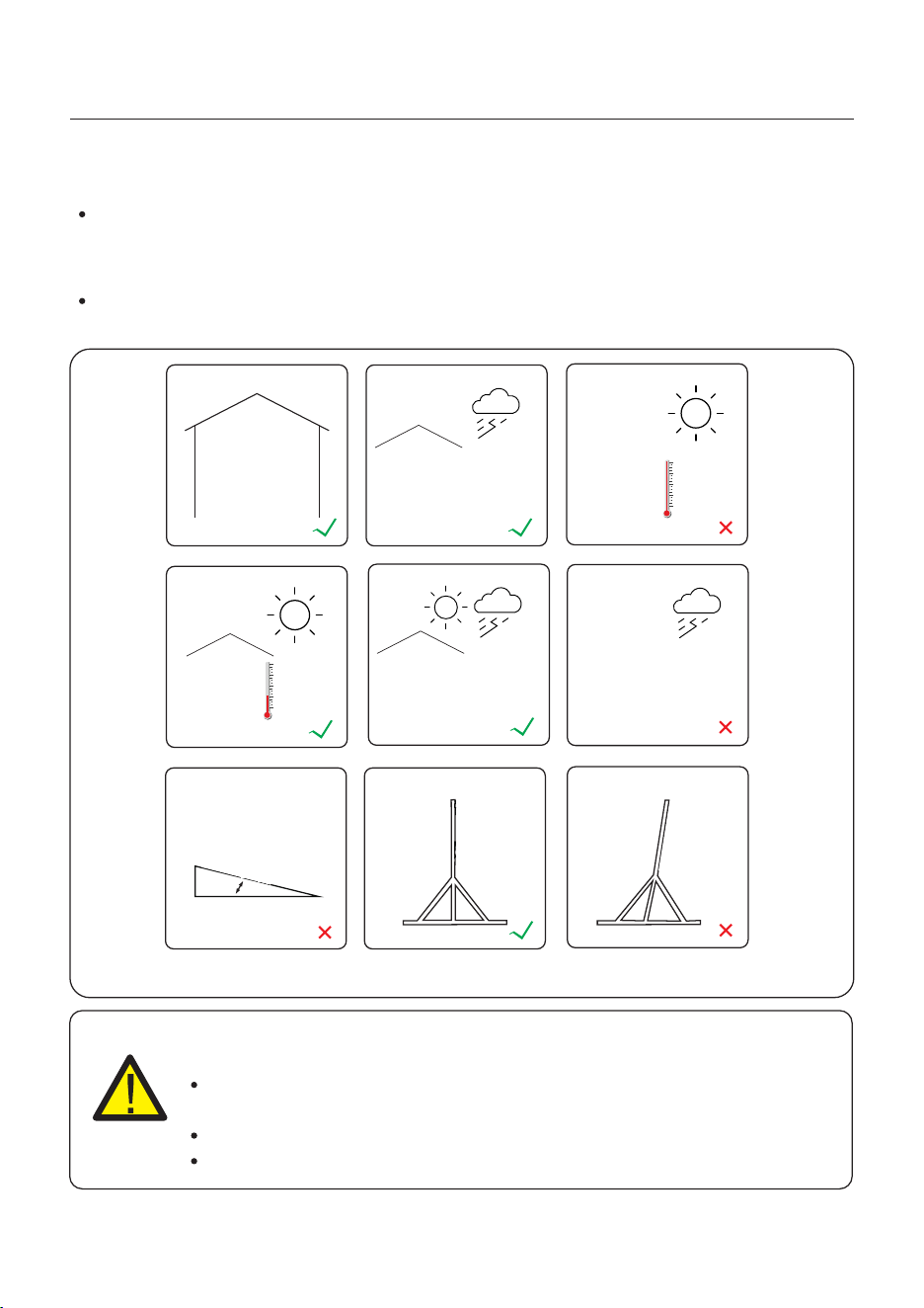
3.1 Select a Location to Install the Inverter
When selecting a location for the inverter, the following criteria should be considered:
Exposure to direct sunlight may cause output power derating due to overheating
It is recommended to avoid installing the inverter in direct sunlight. The ideal location is
one where the ambient temperature does not exceed 40°C.
It is also recommended to install the inverter somewhere the rain and snow will not land
directly on it. The ideal installation location is on a north-facing wall under an eave.
Figure 3.1 Recommended Installation locations
≥15°
Indoor
Direct Sun
Shade Cover
Shade Cover
Direct Rain
Rating
NEMA 4X
11
User Manual
3. Installation
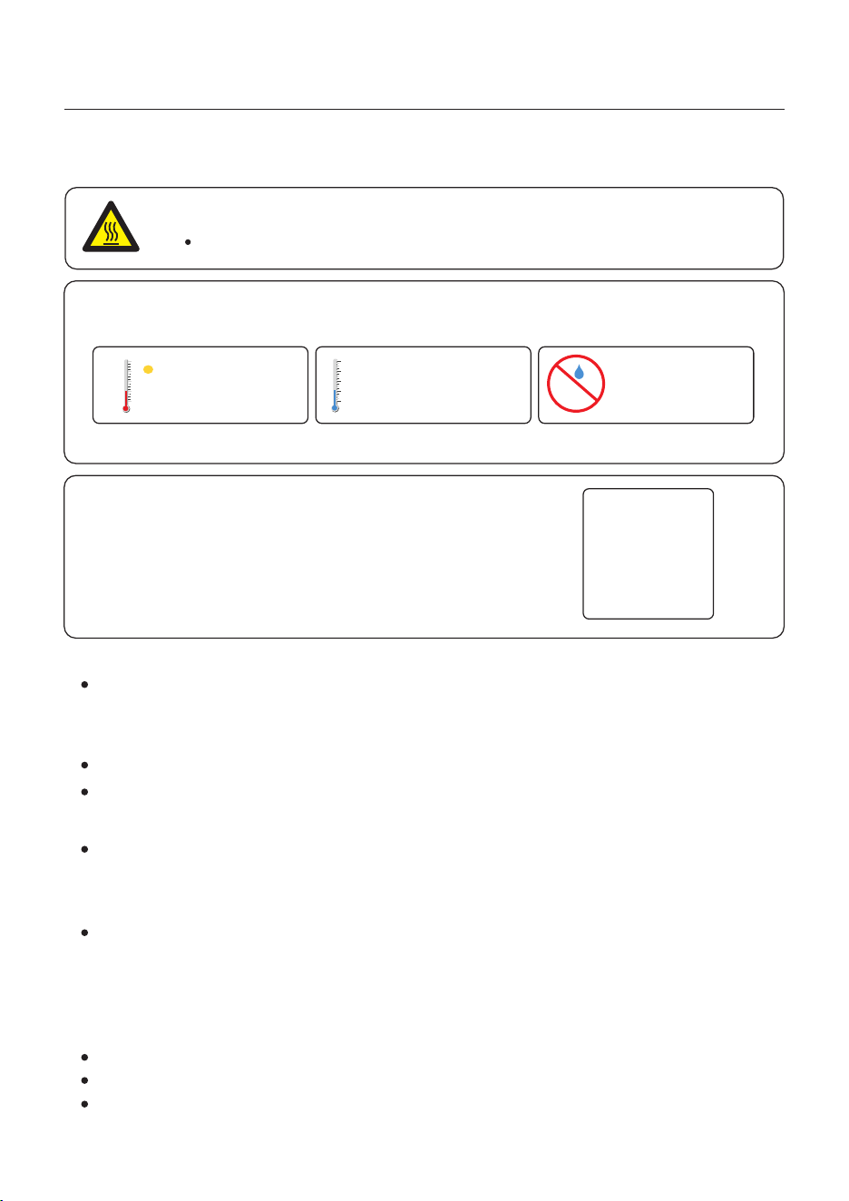
When selecting a location for the inverter, consider the following:
The temperature of the inverter heat-sink can reach 75℃.
The ambient temperature and relative humidity of the installation environment should
meet the following requirements:
If multiple inverters are installed on site, a minimum clearance of 800mm should be kept
between each inverter and all other mounted equipment. The bottom of the inverter should be
at least 1000mm above of the ground or floor.
The LED status indicator lights located on the inverter's front panel should not be blocked
Adequate ventilation must be present if the inverter is to be installed in a confined space.
CAUTION: Hot Surface
Made of non-inflammable materials
Max. load bearing capacity ≥ 4 times of inverter weight.
About the bearing wall. Only supports wall-mounted
installation with solid walls.
3.1.2 Consult technical data
Consult the technical specifications sections at the end of this manual for additional environmental
condition requirements (temperature range, altitude, etc.)
This model of Solis inverter must be mounted vertically (90 degrees or backwards less than or
equal to 15 degrees from 90 degrees straight up).
3.1.3 Angle of installation
3.1.1 Clearances
Load bearing surface:
Installation environment conditions
Max: +60℃ Max: -40℃ Max.RH : 95%
(non-condensing)
12
3.1.4 Avoiding direct sunlight
Installation of the inverter in a location exposed to direct sunlight should to be avoided.
Direct exposure to sunlight could cause:
Power output limitation (with a resulting decreased energy production by the system).
Premature wear of the electrical/electromechanical components.
Premature wear of the mechanical components (gaskets) and user interface.
3.1.6 Flammable substances
Do not install near flammable substances. Maintain a minimum distance of three meters
(10 feet) from such substances.
3.1.7 Living area
Do not install in a living area where the prolonged presence of people or animals is expected.
Depending on where the inverter is installed (for example: the type of surface around the
inverter, the general properties of the room, etc.) and the quality of the electricity supply, the
sound level from the inverter can be quite high.
3.2 Product Handling
3.1.5 Air circulation
Do not install in small, closed rooms where air cannot freely circulate.
To prevent overheating, always ensure that the air flow around the inverter is not blocked.
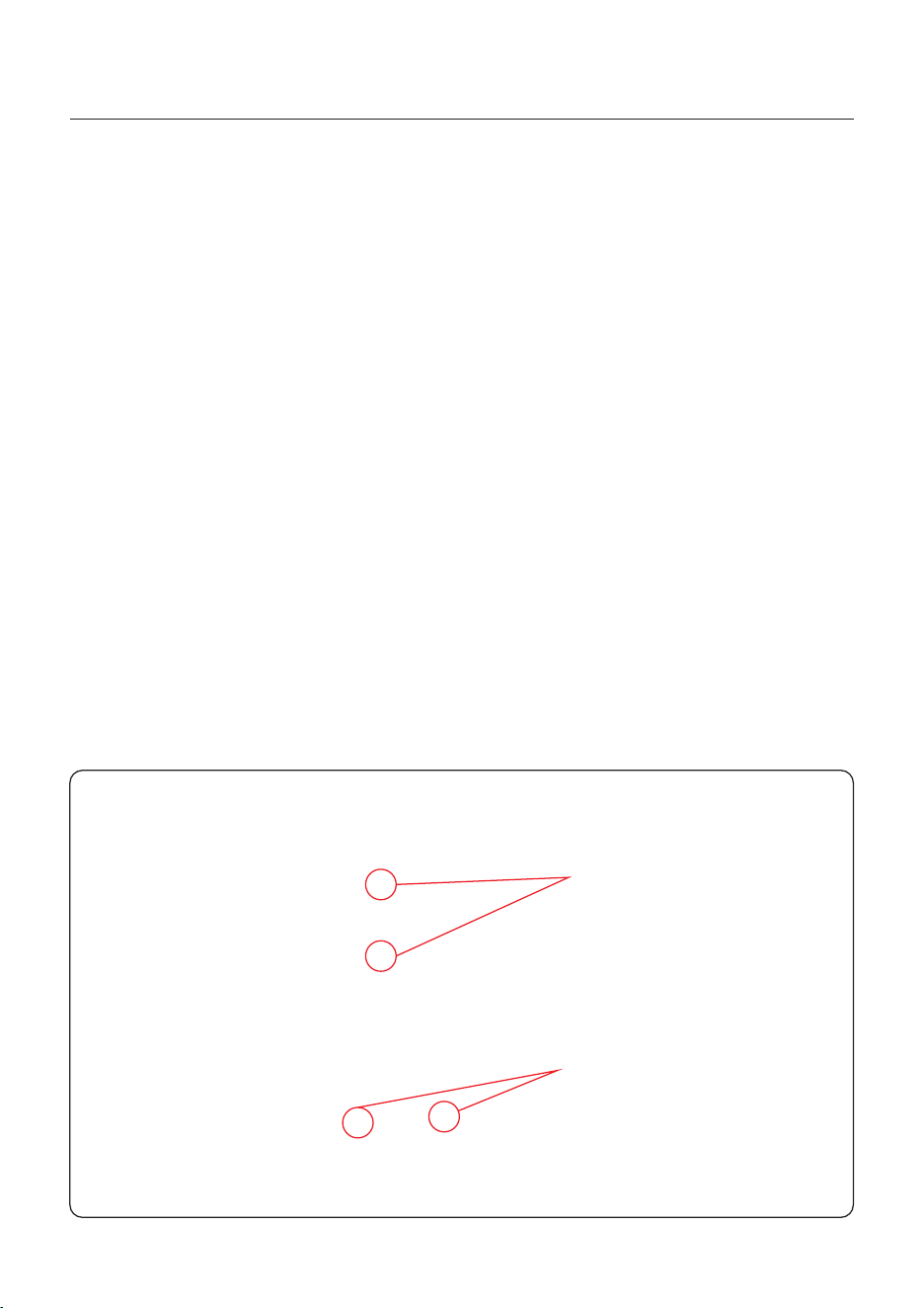
1. After opening the packaging box, stand the inverter upright and place it. When doing this,
operate slowly and gently to ensure that the internal components and the casing do not suffer
any damage.
2. This machine is equipped with 4 black detachable installation handles. You can choose
the appropriate installation position according to your actual needs.
3. The installation positions of the handles are shown in the figure. The red circles represent
the 6 installation positions of the handles (on one side), and there are a total of 12 installation
positions on both sides. When installing, make sure that the installation positions on both
sides are symmetrical.
User Manual
3. Installation
13
2 Installation point of handle
4 Installation points of handle
Figure 3.2
Visibility of the LED indicator lights should be considered.
Adequate ventilation around the inverter must be provided.
NOTE
Nothing should be stored on the top of or placed against the inverter.
The inverter must be mounted vertically with a maximum incline of +/- 5 degree.
Exceeding this may cause the output power to derate.
Figure 3.3 Inverter Mounting Clearances
Mount the inverter on a wall or structure capable of bearing the weight of the machine.
3.3 Mounting the Inverter
User Manual
3. Installation
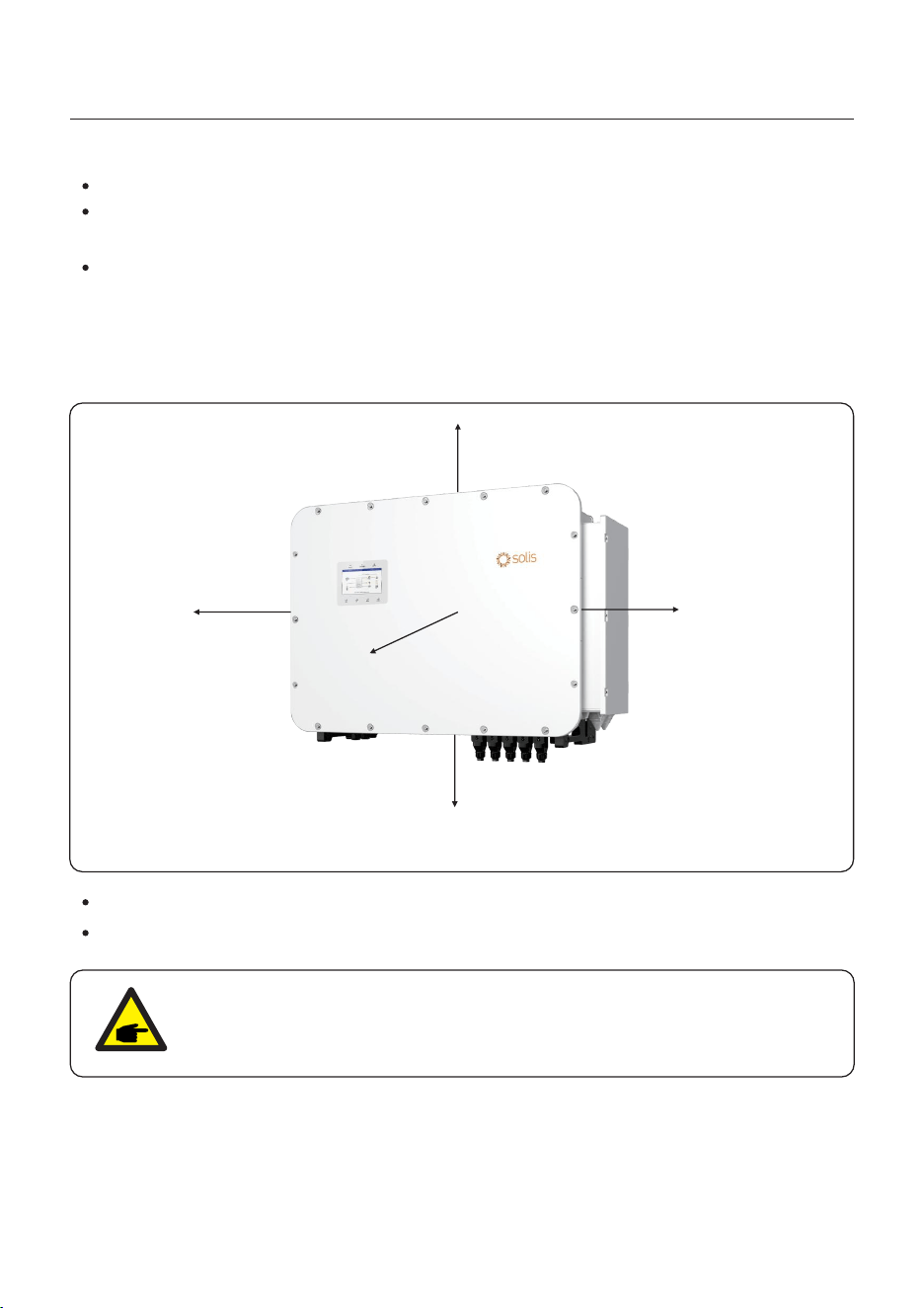
To avoid overheating, always make sure the flow of air around the inverter is not blocked.
For the installation distance, you should refer to the following regulation:
The minimum installation distance from the top is 200mm, 450mm on the left and right,
400mm at the bottom, and 1 meter at the front.
If you choose the wall-mount method, we recommend >1000mm distance at the bottom
≥450mm
≥450mm
≥200mm
≥400mm
≥100
0m
m
14
User Manual
3. Installation
15
The inverter shall be mounted vertically.
The steps to mount the inverter are listed as below:
1. Select the mounting height of the bracket and mark the mounting holes.
For brick walls, the position of the holes should be suitable for the expansion bolts.
WARNING:
The inverter must be mounted vertically.
Once a suitable location has be found according to 3.1 using figure 3.4 mount the wall
bracket to the wall.
Dimensions of mounting bracket:
unit:mm
Figure 3.5 Wall mount bracket
2. Lift up the inverter (be careful to avoid body strain), and align the back bracket on the
inverter with the convex section of the mounting bracket. Hang the inverter on the
mounting bracket and make sure the inverter is secure (see Figure 3.5)
Figure 3.4 Inverter wall mounting
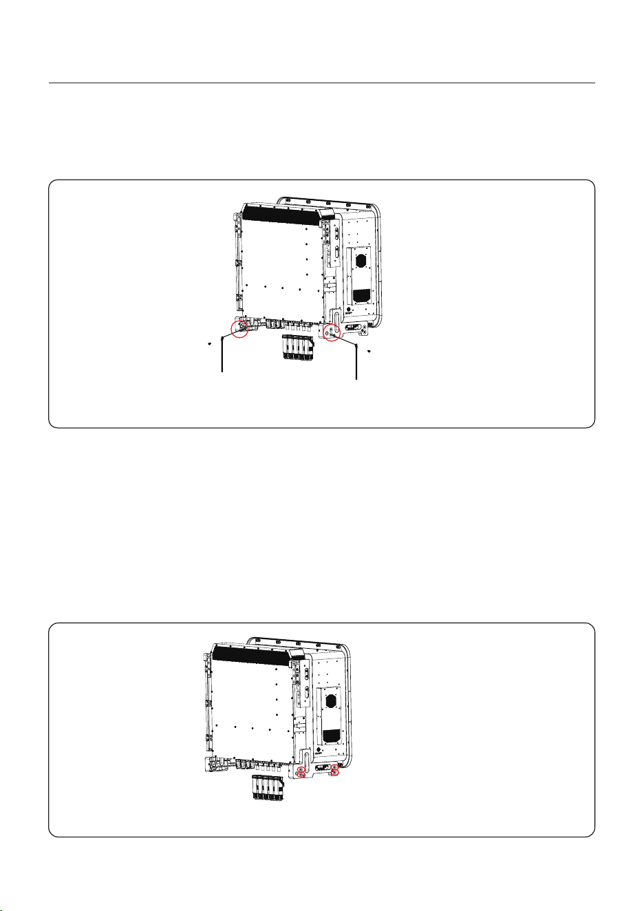
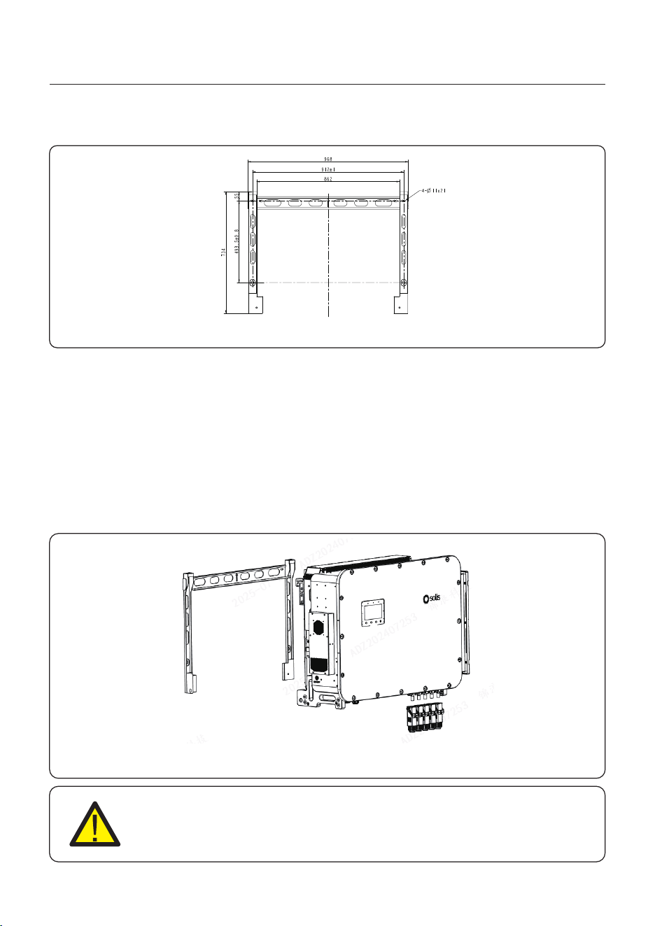
3.4 Ground Cable Installation
User Manual
3. Installation
An external ground connection is provided at the both sides of inverter.
Prepare OT terminals: M10. Use proper tooling to crimp the lug to the terminal.
Connect the OT terminal with ground cable to the right side of inverter. The torque is 10-12N.m.
16
Figure 3.6 Connect the external grounding conductor
M10 Screw removed
Torque: 10-12N.m
Earth wire
External grounding connection terminals are provided on both sides of the bottom bracket of
the inverter. The grounding positions are as shown in the figure, located at the red circles.
There are a total of 8 grounding positions on both sides.
Terminal type: OT terminal; Bolt type: M10. Use the appropriate tool to press the wire onto
the terminal block.
Connect the OT terminal to both sides of the inverter, with a torque of 10-12 Nm.
To connect the grounding terminal of the bottom bracket, it is recommended to use copper
wire. Solis conductors or stranded wires can be used. The specific wire size should refer to
local standards and regulations.
Earth wire
Figure 3.7
User Manual
3. Installation
17
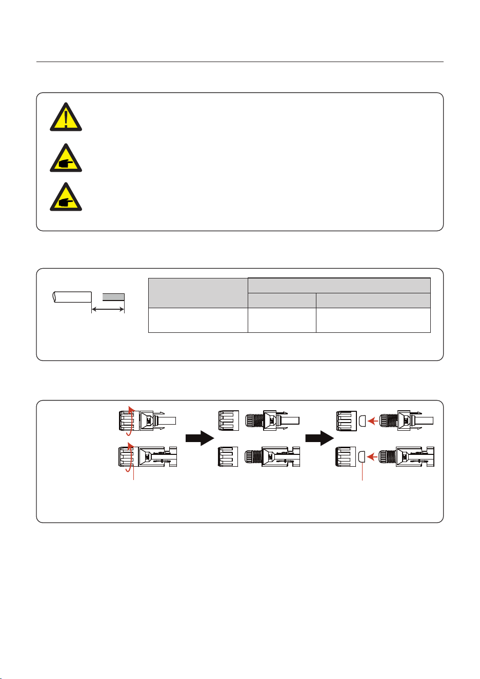
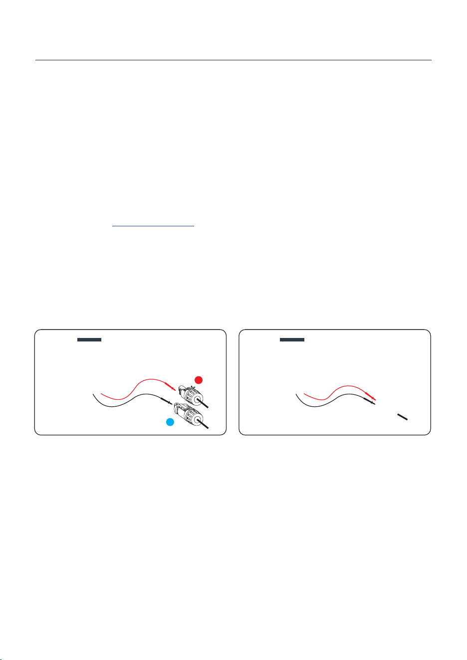
3.5 PV Cable Installation
Negative terminal
Positive terminal
Before connecting inverter, please make sure the PV array open circuit
voltage is within the limit of the inverter.
Please use approved DC cable for PV system.
4.0~6.0
4.0(12AWG)
(12~10AWG)
Cable type
Cross section(mm²)
Range
Industry generic P V cable
Recommended value
1. Select a suitable DC cable and strip the wires out by 7±0.5mm. Please refer to the table
below for specific specifications.
7±0.5mm
2. Take the DC terminal out of the accessory bag, turn the screw cap to disassemble it,
and take out the waterproof rubber ring.
Nut Waterproof collar
Figure 3.8
Figure 3.9
Before connection, please make sure the polarity of the output voltage of
PV array matches the“DC+”and“DC-”symbols.
User Manual
3. Installation
18
Negative terminal
Positive terminal
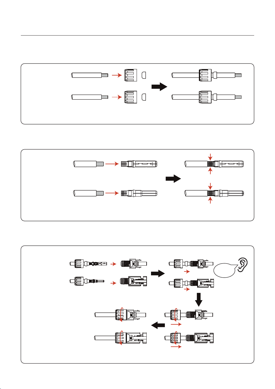
3. Pass the stripped DC cable through the nut and waterproof rubber ring.
4. Connect the wire part of the DC cable to the metal DC terminal and crimp it with a special
DC terminal crimping tool.
Negative terminal
Positive terminal
Squeeze
5. Insert the crimped DC cable into the DC terminal firmly, then insert the waterproof rubber
ring into the DC terminal and tighten the nut.
Tighten
After you hear a "click", pull gently to check for a firm engagement.
Click
Negative terminal
Positive terminal
Figure 3.10
Figure 3.11
Figure 3.12
User Manual
3. Installation
19
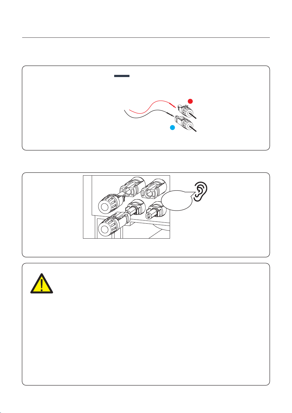
6. Measure PV voltage of DC input with multimeter, verify DC input cable polarity.
7. Connect the wired DC terminal to the inverter as shown in the figure, and a slight
"click" is heard to prove the connection is correct.
+
-
CAUTION:
If DC inputs are accidently reversely connected or inverter is faulty or not
working properly, it is NOT allowed to turn off the DC switch. Otherwise it
may cause DC arc and damage the inverter or even lead to a fire disaster.
The correct actions are:
*Use a clip-on ammeter to measure the DC string current.
*If it is above 0.5A, please wait for the solar irradiance reduces until the
current decreases to below 0.5A.
*Only after the current is below 0.5A, you are allowed to turn off the DC
switches and disconnect the PV strings.
* In order to completely eliminate the possibility of failure, please disconnect
the PV strings after turning off the DC switch to aviod secondary failures due
to continuous PV energy on the next day.
Please note that any damages due to wrong operations are not covered in
the device warranty.
Figure 3.13
Figure 3.14
Click
User Manual
3. Installation
3.6 Battery Cable Installation
DANGER
Before installing the battery cables, be sure that the battery is turned off.
Use a multimeter to verify that the battery voltage is 0Vdc before proceeding.
Consult the battery product manual for instructions on how to turn it off.
20
NOTE
Recommended Fuse: Ue≥1000Vdc, In≥150A, Breaking Capacity ≥ DC 50KA,
Altitude: 0~2000m(no derating), Environment temperature: -5℃~40℃ (no
derating). Recommended Breaker: Ue≥1000Vdc, In≥125A,
Breaking Capacity ≥ DC 50KA, Ii≥625A, Altitude:0~2500m(no derating),
Environment temperature: -40℃~55℃ (no derating).
A
B
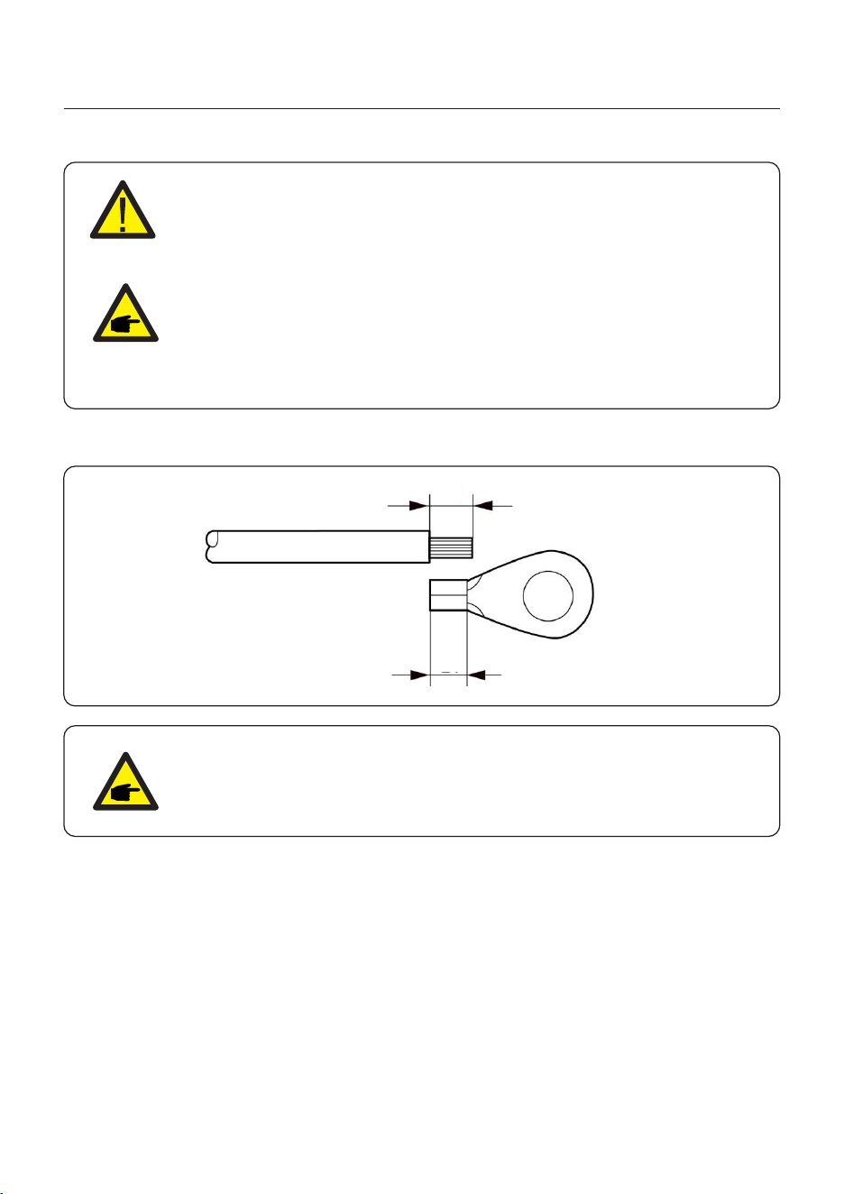
External cable connection:
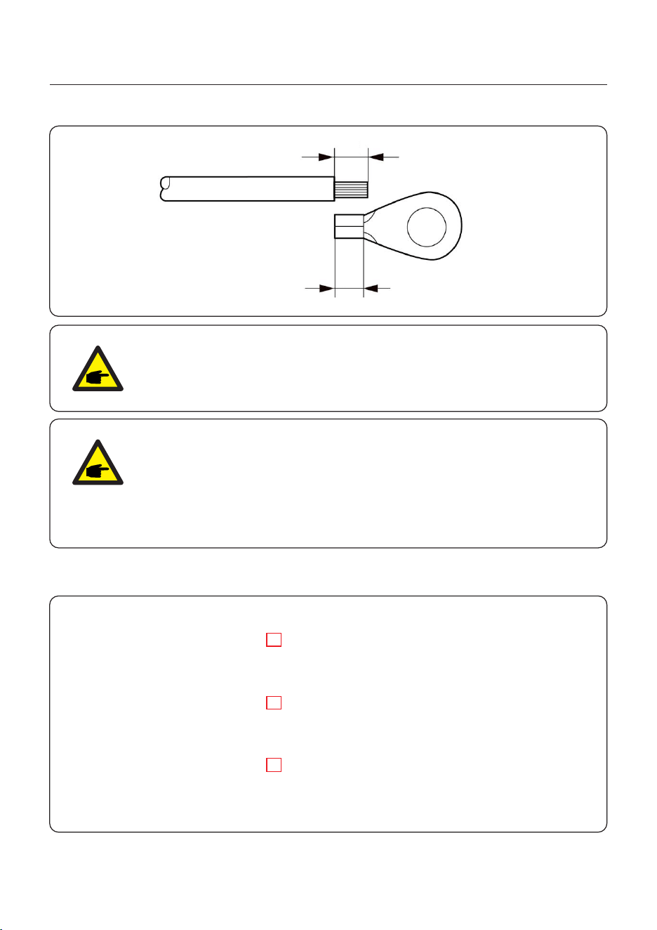
Dimension of stripping cable:
Battery cable: 25.0~35.0mm²(2AWG/3AWG)
Copper Lug: M6
Torque: 4~5N.m
Not support Aluminum cable connection
NOTE
B (insulation stripping length) is 2mm - 3mm longer than A (OT cable
terminal crimping area).
User Manual
3. Installation
21
3.7 AC Wiring
BACKUP
Wire Size 0AWG/1AWG 0AWG/1AWG 00AWG/000AWG 1AWG/2AWG
Cable 70-95mm² 70-120mm² 95-150mm² 50-70mm²
Fastener
specifications
M8 M12 M12 M10
Torque 10-12N.m 20-30N.m 20-30N.m 10-12N.m
If support
aluminum cable
connection?
YES (But supported
the maximum
diameter is 95 mm2)
YES YES YES
BACKUP
SMARTLOAD/
GEN/INV
GRID PE
SMARTLOAD/
GEN/INV
GRID
PE
Detailed wiring steps are as follows:
1. Disconnect the AC circuit breaker to ensure it won't accidentally turn on.
2. Strip a certain length from the end of the AC cable insulation sheath. The stripping length
can be referred to in the following figure. Place the R-type terminals on both ends and make a
crimp connection. The crimped part of the terminals must be insulated with heat shrink tubing
or insulating tape.
NOTE
Recommended Breaker of Backup port and Smart port:
Ue≥400Vac, In>225A, Ics>AC 50KA, Altitude:0-2500m(No derating),
temperature: -35℃ 40℃(No Frequency reduction).
Recommended Breaker of Grid port:
Ue≥400Vac, In>315A, Ics>AC 50KA, Altitude:0-2500m(No derating),
temperature: -35℃ 40℃(No Frequency reduction).
Recommended External RCD: IΔn≥500mA
Max inverter backfeed current to PV array: Current 0A , Continuous 0 ms.
Maximum output fault current on grid port:
Max.peak current: 520A, total duration:132ms.
Current (inrush)on grid port: Max.peak current 50A , Max duration 9.2ms.
User Manual
3. Installation
22
A
B
NOTE
B (insulation stripping length) is 2mm - 3mm longer than A (OT cable
terminal crimping area).
NOTE
Currently, aluminum wire connections are supported, but the backup
aluminum wire can only reach a maximum of 95 mm2. If it exceeds 95 mm2,
load reduction may be required; the wire nose can only use copper-aluminum
alloy (the copper-aluminum alloy wire nose is configured according to the
selected cable).
4. When connecting to the grid port and the SMARTLOAD/GEN/INV ports, remove the three
screws on the cover of the inverter junction box, and then remove the junction box cover.
User Manual
3. Installation
23
5. Select the matching diameter of the outlet sealing ring according to the diameter of the AC
cable. Cut the diameter of the sealing ring to the appropriate size, pass the cable through the
sealing ring, remove the nut at the corresponding position of the wiring box, and use a socket
wrench to connect the cable to the corresponding AC terminal block in sequence. The torque
should follow the recommended torque in table.
6. To ensure the waterproof effect, the operator needs to regularly check if the sealing ring is
damaged.
7. When the cable is coming out in right wiring box, there should be no openings or gaps
between the tower protective sleeve and the cable.
8. After the AC cable are wired, the cables should be fixed, The installers should use the
ribbon to secure the wire harnessed in the holes of the surrounding metal shells.
3.8 CT Connection
CAUTION:
Make sure the AC cable is totally isolated from AC power before
connecting the or CT.
The CT provided in the product box is compulsory for hybrid system installation. It can be used
to detect the grid current direction and provide the system operating condition to hybrid inverter.
CT Model: AKH-0.66-K-80*40-600A
CT Cable: Size – 0.8mm², Length – 5m, its extension not supported.
CT connection: On the inverter side, it is directly inserted through the quick-insert terminal;
on the grid side, it is connected through the U-shaped terminal.
Solis marked the CT cable in 6 different colors .lead the CT cables through the COM 1 port of
inverter bottom.
CT Wire
Black
Pin 1 (From Left to Right) L1CT+
Pin 2 (From Left to Right) L1CT-
Pin 3 (From Left to Right) L2CT+
Pin 4 (From Left to Right) L2CT-
Pin 5 (From Left to Right) L3CT+
Pin 6 (From Left to Right) L3CT-
Purple
Blue
Green
8 PIN Communication Terminal Block Print name
3.8.1 CT Installation
Orange
Yellow
User Manual
3. Installation
24
NOTE:
When install the CT , On the CT, label P1 faces the inverter side and P2 faces
the power grid side.
User Manual
3. Installation
25
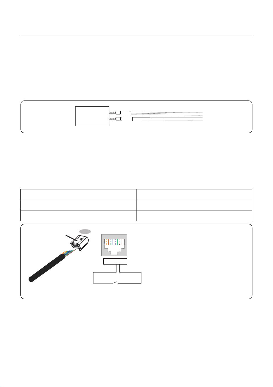
3.9 Inverter Communication
3.9.1 Communication Ports
Wiring steps for COM1-COM2:
Step 1. Loose the cable gland and remove the watertight caps inside the cable gland based
on the number of the cables and keep the unused holes with watertight cap.
Step 2. Lead the cable into the holes in the cable gland.
(COM1: 4-hole fastening rings inside the cable . Hole Diameter: 5.3mm.
COM2: 10-hole fastening rings inside the cable . Hole Diameter:1.5mm.)
Step 3. Connect the cable to the corresponding terminals inside the wiring box.
Step 4. Reassemble the cable gland and ensure there is no bending or stretching of the cables
inside the wiring box.
NOTE:
Please separate the gap with hand and squeeze
the cables into the holes from the side openings.
User Manual
3. Installation
26
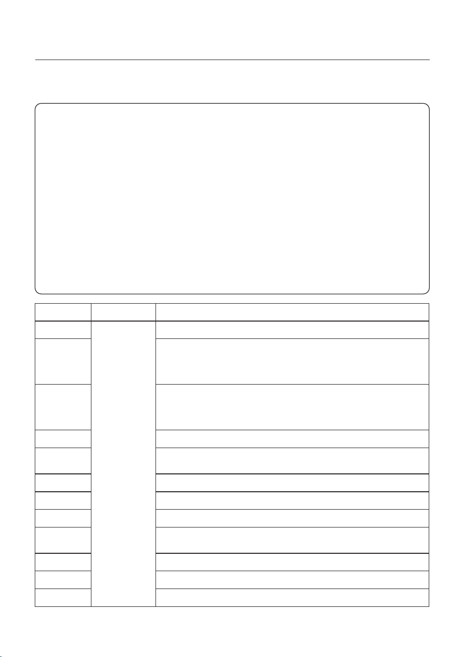
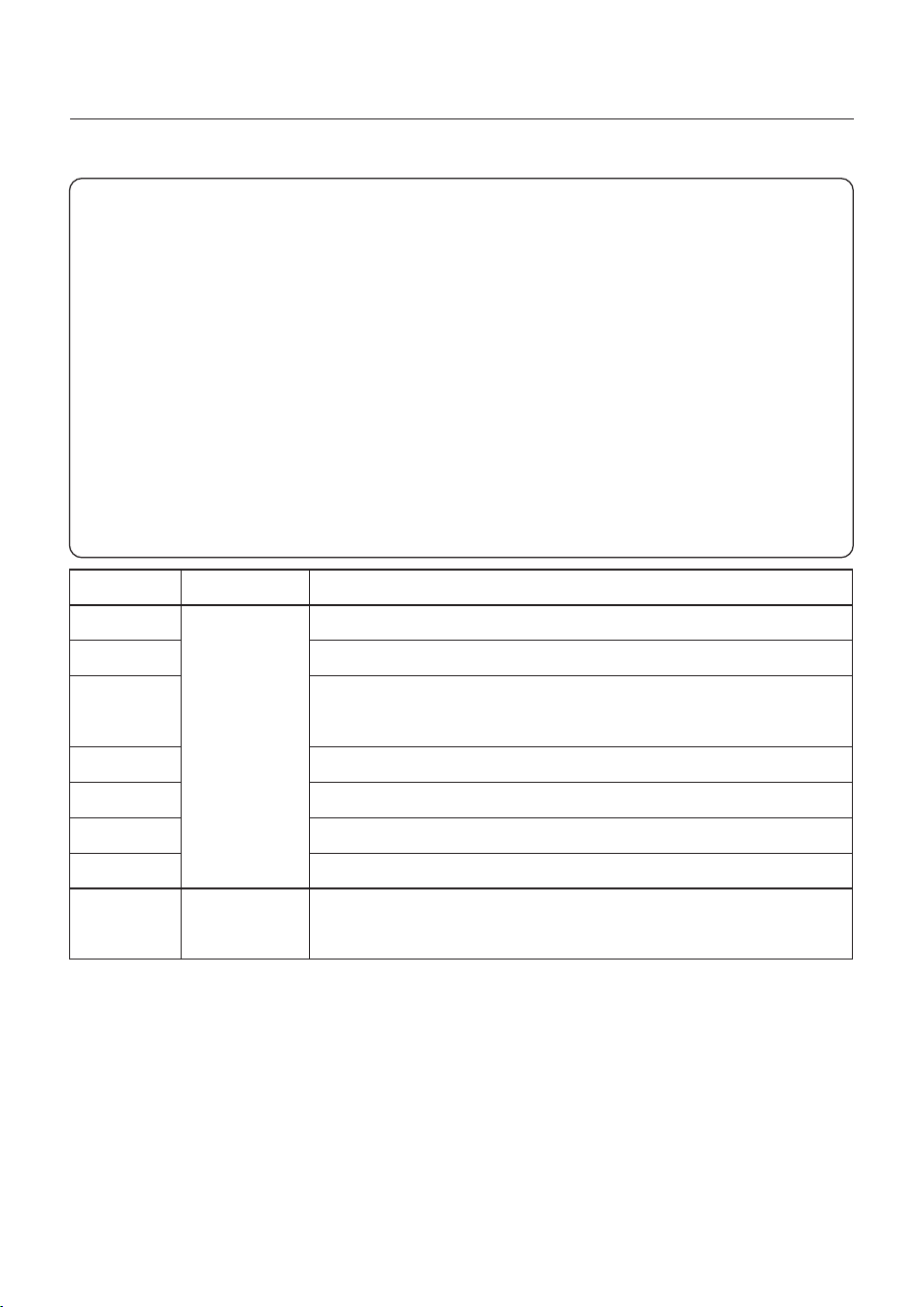
3.9.2 Communication Terminals
Terminal
CT
RSD
EPO
ATS
ATSW
FREE
GS
GV
ACCP
HEST
RS485
METER
DescriptionType
Push-In
Terminal
For CT connection.
The positive and negative electrodes are short-circuited at
the factory, the inverter will stop when disconnected.
If customer has the requirement for RSD Function They need
to use an external switch or external controller to control it.
Same logic as RSD function, Customized functions can be
accepted from customers, allowing them to choose whether
to shut down the system or merely stop PV output on this
function.
Used for external ATS dry contact signal transmission.
Used for external power adoptor(DC12V/5V) dry contact
signal transmission.
Reserved for customized function.
Used for Generator start/stop signal.
Used for Generator start/stop signal.
Used for hybrid inverter control the external breaker to cutoff
the PV inverter AC connection with hybrid inverter smart port.
Used for heat pump.
Used for 3rd party device control.
Used to meter connection.
User Manual
3. Installation
Terminal
BMS1
BMS2
ETH
PARA
PARA
EMS
DRM
DIP Switch
DescriptionType
RJ45
Connector
For battery communication (CAN protocol).
For battery communication (CAN protocol).
Ethernet port, support TCP/IP, used for other external
communication, the standard Ethernet Port definition:
1-TX+,2-TX-,3-RX+,6-RX-.
For parallel mode connection between inverters.
For parallel mode connection between inverters.
For external 3rd party EMS control.
For DRM function requirement in some regions.
If a inverter is set as the first or last inverter in the parallel
connection, you need to put all the DIP switch on this inverter
to ON state , and the middle machine should be on OFF state.
Switch
27
User Manual
3. Installation
28
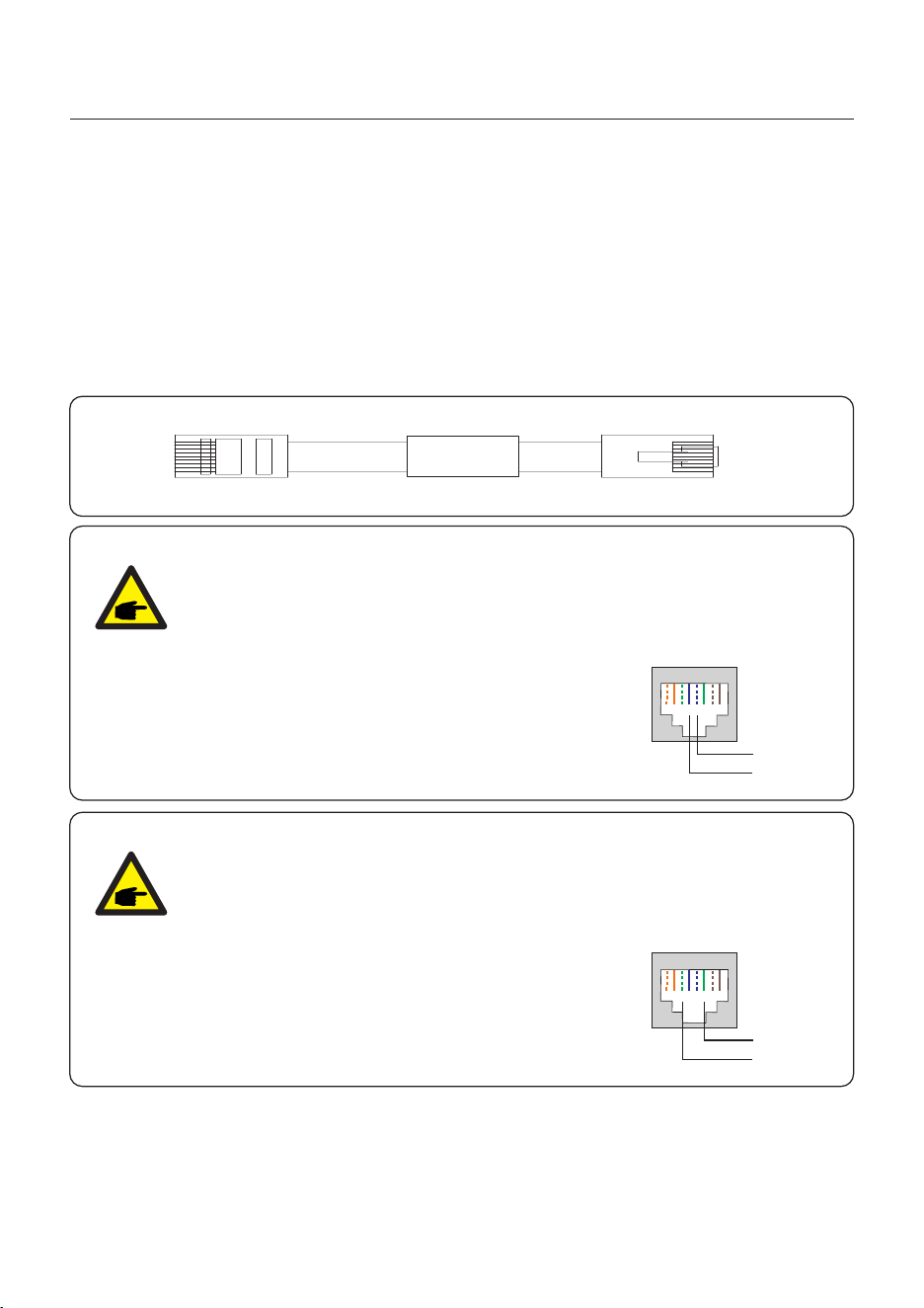
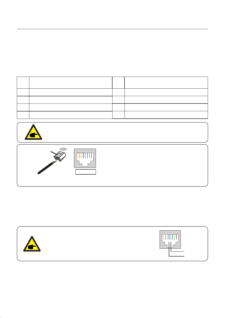
3.9.3 BMS Terminal Connection
CAN communication is supported between inverter and compatible battery models.
Please lead the CAN cable through the COM1 or COM2 port of the inverter and connect to
the BMS terminal with RJ45 connector.
NOTE:
Before connecting CAN cable with the battery, please check whether the
communication pin sequence of the inverter and the battery match;
If it does not match, you need to cut off the RJ45 connector at one end of the
CAN cable and adjust the pin sequence according to the pin definitions of
both inverter and battery.
Pin definition of the inverter BMS Port is following
EIA/TIA 568B.
CAN-H on Pin 4: Blue
CAN-L on Pin 5: Blue/White
RJ45terminal
1 2 3 4 5 6 7 8
CAN-L
CAN-H
CAN
3.9.3.1 With Lithium Battery
NOTE:
Before connecting RS485 cable with the battery, please check whether the
communication pin sequence of the inverter and the battery match;
If it does not match, you need to cut off the RJ45 connector at one end of the
RS485 cable and adjust the pin sequence according to the pin definitions of
both inverter and battery.
Pin definition of the inverter BMS Port is following
EIA/TIA 568B.
RS485A on Pin 6: Green
RS485B on Pin 3: Green/White
RJ45terminal
1 2 3 4 5 6 7 8
RS485A
RS485B
Inverters of this series type support that customers using the batteries with different capacity
and with different specification, but Solis recommend that using the batteries with same
specification is better for the whole inverter system work excellently.
User Manual
3. Installation
29
3.9.4 Meter Terminal Connection
The smart meter using the MODBUS as communication protocol, when you want to use the
smart meter measurement, you should lead the RS485 meter cable through the com1 port of
inverter bottom.
Lead the meter RS485 A cable to 21 pin, RS485 B cable to 22 pin in the internal quick-plug
terminal of inverter.
3.9.5.1 For Remote Shutdown Function
Solis inverters support remote shutdown function to remotely control the inverter to power on
and off through logic signals.
The DRM port is provided with an RJ45 terminal and its Pin5 and Pin6 can be used for remote
shutdown function.
Signal
Short Pin5 and Pin6 Inverter Generates
Inverter Shutdown in 5s
Open Pin5 and Pin6
Function
Correspondence between the cables
and the stitches of plug, Pin5 and Pin6
of RJ45 terminal is used for the logic
interface, other Pins are reserved.
Pin 1: Reserved; Pin 2: Reserved
Pin 3: Reserved; Pin 4: Reserved
Pin 5: Switch_input1; Pin 6: Switch_input2
Pin 7: Reserved; Pin 8: Reserved
1--8
Rj45 plug
RJ45terminal
1 2 3 4 5 6 7 8
1 2 3 4 5 6 7 8
DRM(logic interface)
Switch input1_ Switch input2_
Figure 3.15 Strip the insulation layer and connect to RJ45 plug
3.9.5 DRM Port Connection (Optional)
METER
A
B
User Manual
3. Installation
30
Assignment for inverters capable
of both charging and discharging
Pin
1
DRM 1/5
2
DRM 2/6
3
DRM 3/7
4
DRM 4/8
5
RefGen
6
7
8
Com/DRM0
V+
V-
Assignment for inverters capable
of both charging and discharging
Pin
DRED means demand response enable device. The AS/NZS 4777.2:2020 required inverter
need to support demand response mode(DRM).
This function is for inverter that comply with AS/NZS 4777.2:2020 standard.
A RJ45 terminal is used for D RM connection.
3.9.5.2 For DRED Control Function (For AU and NZ Only)
NOTE:
Solis hybrid inverter is designed to provide 12V power for DRED.
3.9.6 RS485 Port Connection (Optional)
Figure 3.16 Strip the insulation layer and connect to RJ45 plug
Correspondence between the
cables and the stitches of plug
Pin 1: white and orange ; Pin 2: orange
Pin 3: white and green; Pin 4: blue
Pin 5: white and blue; Pin 6: green
Pin 7: white and brown; Pin 8: brown
1--8
RJ45 plug
RJ45terminal
1 2 3 4 5 6 7 8
1 2 3 4 5 6 7 8
This port only supports RS485 communication protocol, and it can be used as a master
controller port to control the other equipment, such as: on-gird inverter, if you need the
communication protocol document, please contact the Solis local service team or Solis
sales to get the latest version.
NOTE:
Pin definition of the RS485 Port is following
EIA/TIA 568B.
RS485A on Pin 5: Blue/White
RS485B on Pin 4: Blue
RJ45terminal
1 2 3 4 5 6 7 8
RS485A
RS485B
31
User Manual
3. Installation
Up to 6 units of the inverter can be connected in parallel, if you have demand for 7-10 pcs in
parallel mode, you should ask local solis technology support.
Please connect the paralleled inverters by using P-A and P-B terminals.
Standard CAT5 with shielding layers internet cable can be used.
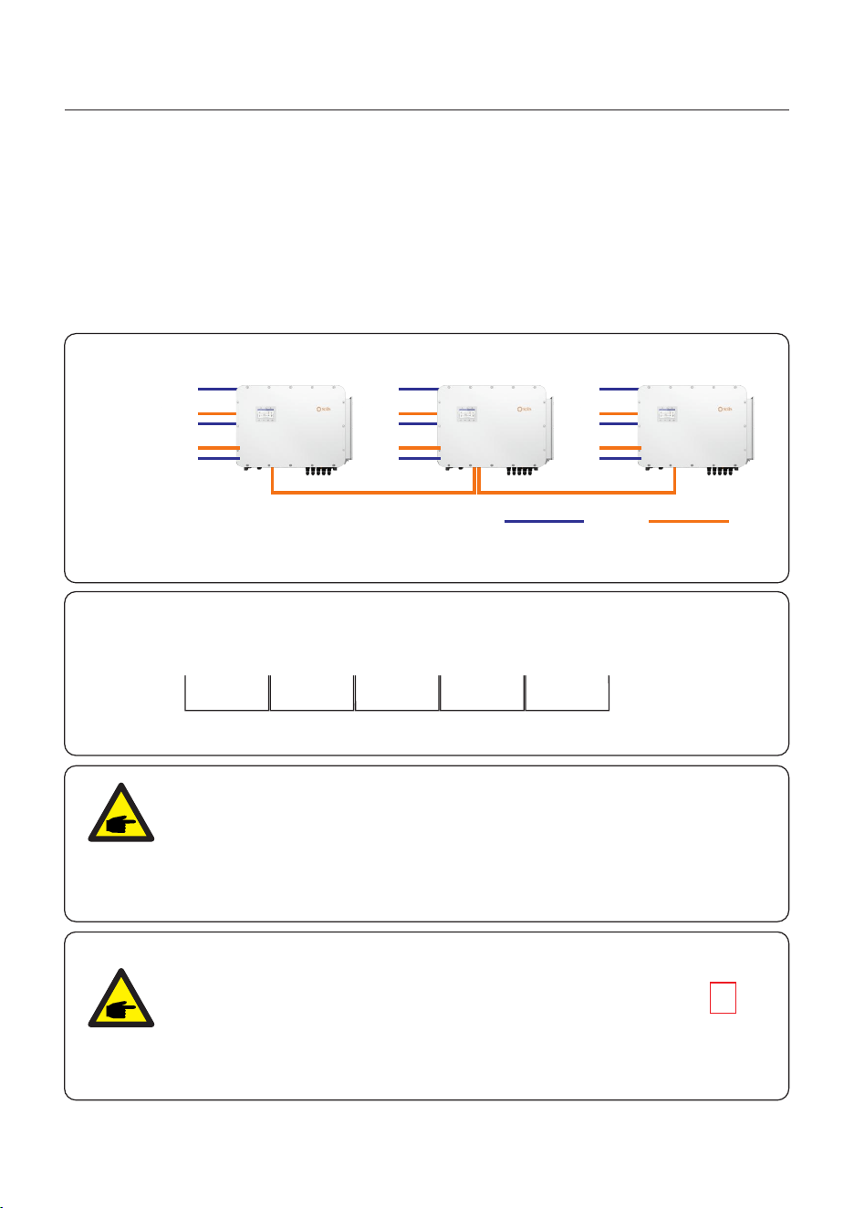
3.9.7 Parallel Inverter Connection (Optional)
1. ALL inverter MUST be connected to their own HV battery.
2. NOT support two or more inverters connect to the same one battery.
P_B P_A P_B P_A P_B P_A P_B P_A P_B P_A
Figure 3.18 Parallel Terminal Connection
Master Slave1 Slave2 Slave3 Slave4 Slave5
Figure 3.17
NOTE:
In a parallel system, if the battery number configuration is not one-to-one
sufficient, only the slave machine can be left unconnected, while the master
machine must be connected to the battery.
And the battery which one has the highest capacity we recommend you
connect it to master machine is better for system stability.
PV module
Battery 1
Battery 2
Master
CANDC
Slave Slave
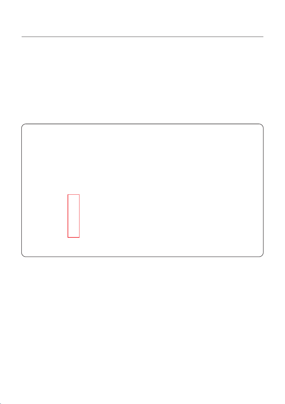
NOTE:
If the parallel machine is connected to the first and
last consoles of the parallel connection, you need
to put the DIP switch on the ARM board to “ON”
position, and all the middle machines’ DIP switch
should be put to “OFF” position.
32
User Manual
3. Installation
The G-S(Pin11,Pin12), G-V(Pin13,Pin14) are DO ports. You can use this ports to output dry
contact signal to generator to control the generator start or stop automatically.
The ATS (Pin5, Pin6), ATS-W (Pin7, Pin8) are DI ports, If you have installed generator with
ATS device. You can use the this ports connect to ATS or Power Adaptor(12V/5V) to detect
the power grid state, if grid tripped, the ATS OR Power Adaptor will send dry contact signal to
hybrid inverter.
3.9.8 Generator communication connection(G-S/G-V/ATS/ATS-W)
User Manual
3. Installation
33
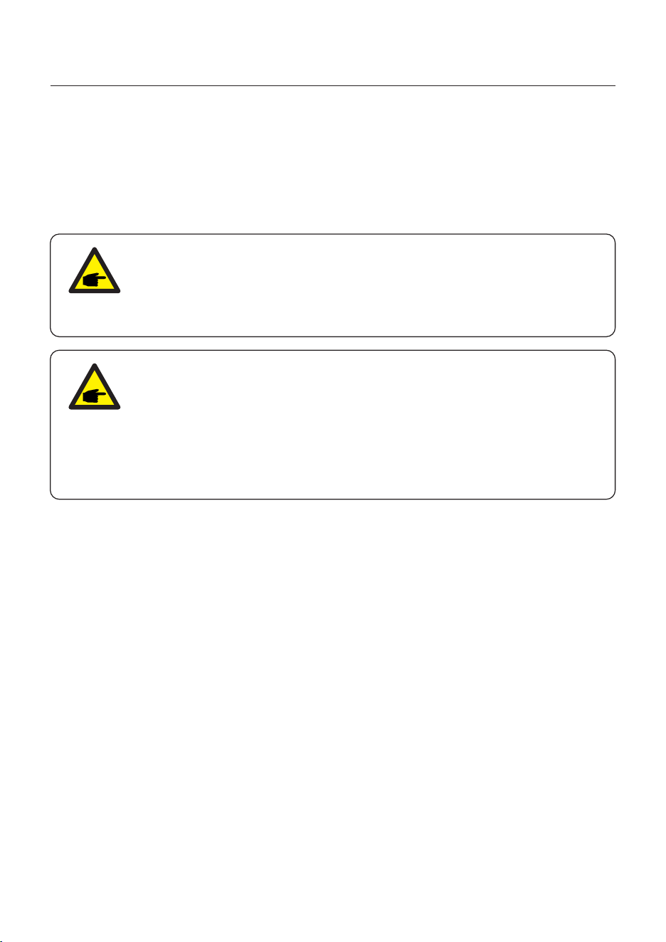
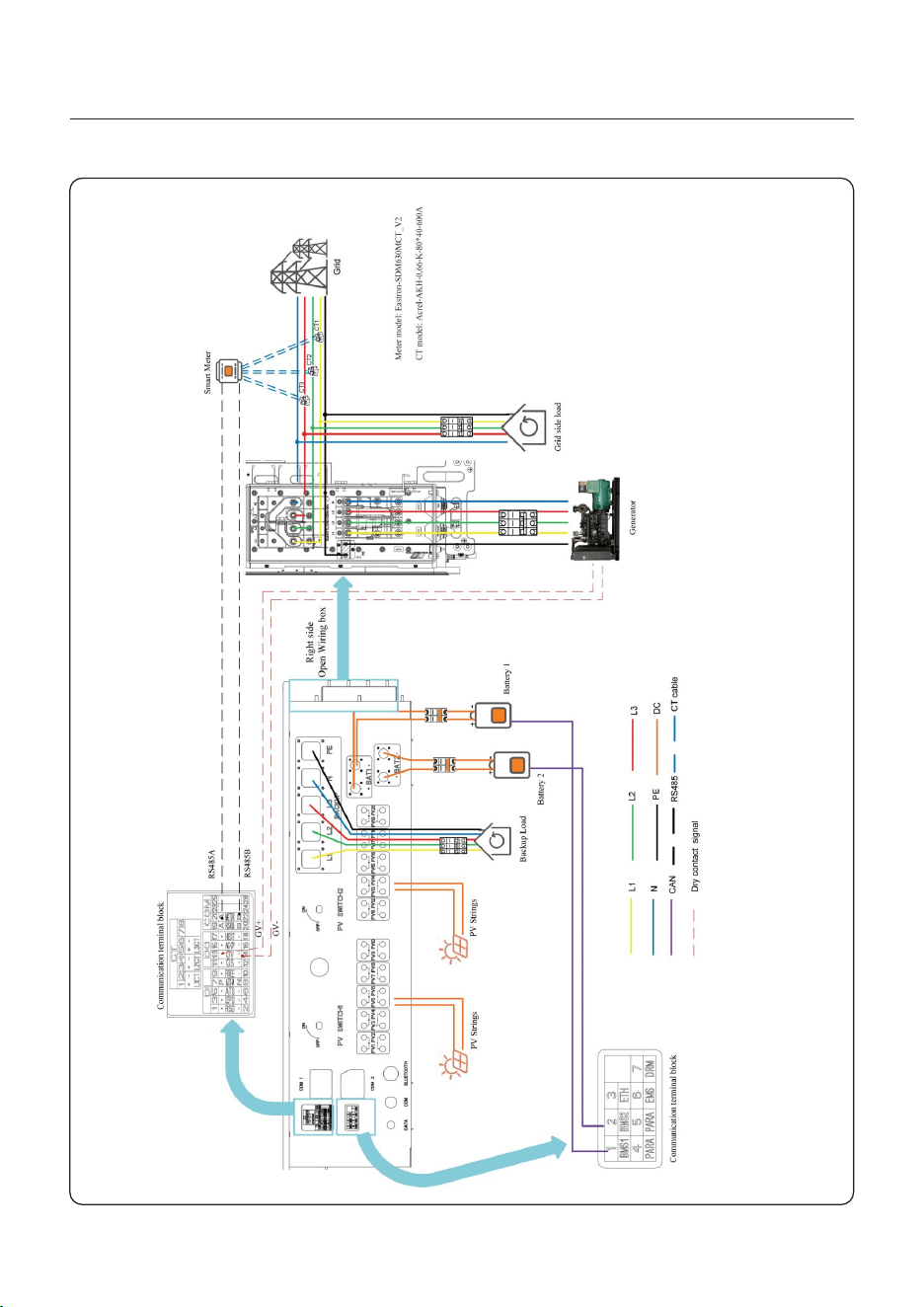
3.10 Generator Wiring
1.The backup PE must be directly connected to the PE copper bar of the power distribution
box, rather than the inverter shell.
2.The generator itself needs to be grounded, connected to the electric box, and connected
to the inverter generator port.
3. When the generator is working, disconnect the Grid breaker or leakage current protector
on the side of the power box immediately.
NOTE:
If you want use the smart port to connect a generator, there is no limit to
the generator capacity. However, the maximum active power that the smart
port can obtain from the generator is 125kW.We recommend that the
generator power should be in the range: 25kW~125kW
NOTE:
If you need connect the generator on inverter smart port or inverter grid
port, when you are connecting the power cable, you should keep the cable
conned in right correspond phase sequence. For example: if you do the
wrong operation , like connecting the A phase point form Inverter to the B or
C phase point from generator, when you want start generator, the inverter
will report alarm and the generator cannot start normally!
34
User Manual
3. Installation
Figure 3.19
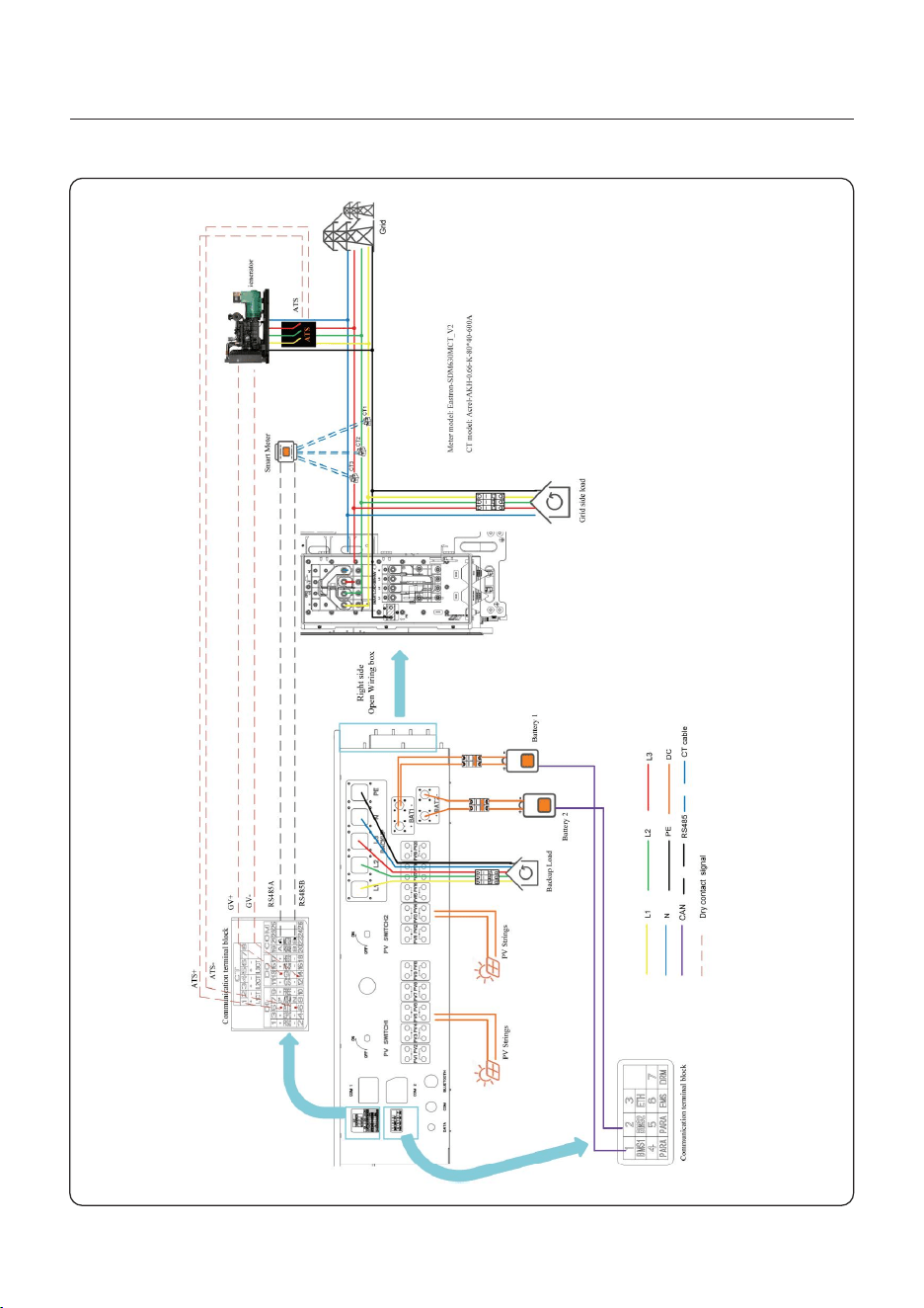
Figure 3.20
User Manual
3. Installation
35
User Manual
3. Installation
3.11 Parallel System Wiring
36
NOTE:
When under parallel system(inverter amount > 2), the AC cable length
difference from inverter grid/backup port to the busbar should not exceed 10%.
Figure 3.21
User Manual
3. Installation
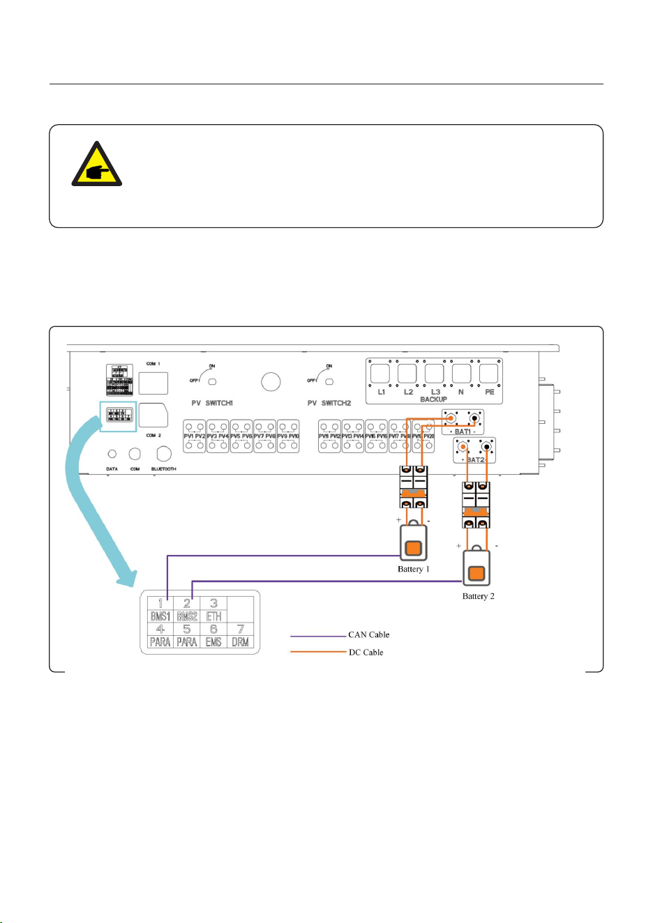
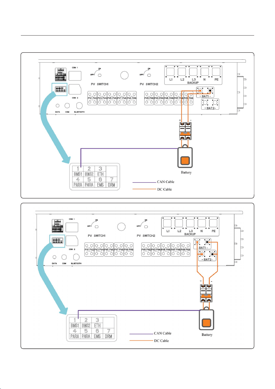
3.12 Lithium Battery Wiring
Inverter supports the 3 wirings methods to connect to lithium battery.
If you have only one battery, you MUST connect it to DC 1 port on inverter, and communication
cable MUST be connected to BMS 1 port on the inside terminal block.
37
NOTE:
If the inverter amount ≥2 in parallel mode on site, you must set the parallel
mode on Solis app for each inverter in case of avoiding the damage to inverter
when power on, the specific setting method can refer to the chapter 5.5.5
Parallel setting.
User Manual
3. Installation
38
User Manual
3. Installation
Figure 3.22
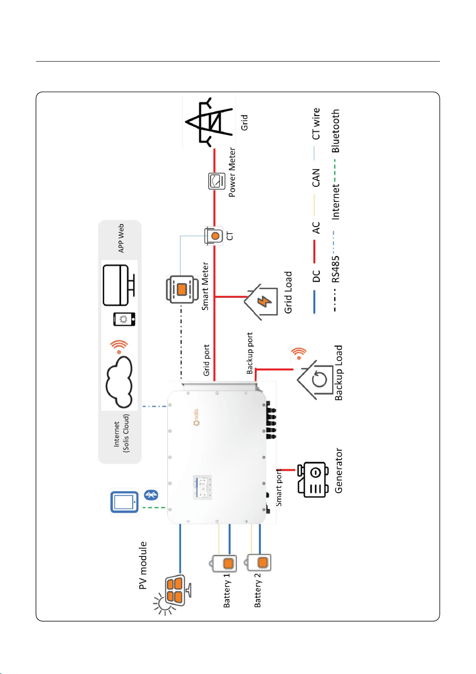
3.13 Smart Meter measurement connection method for system
39
User Manual
3. Installation
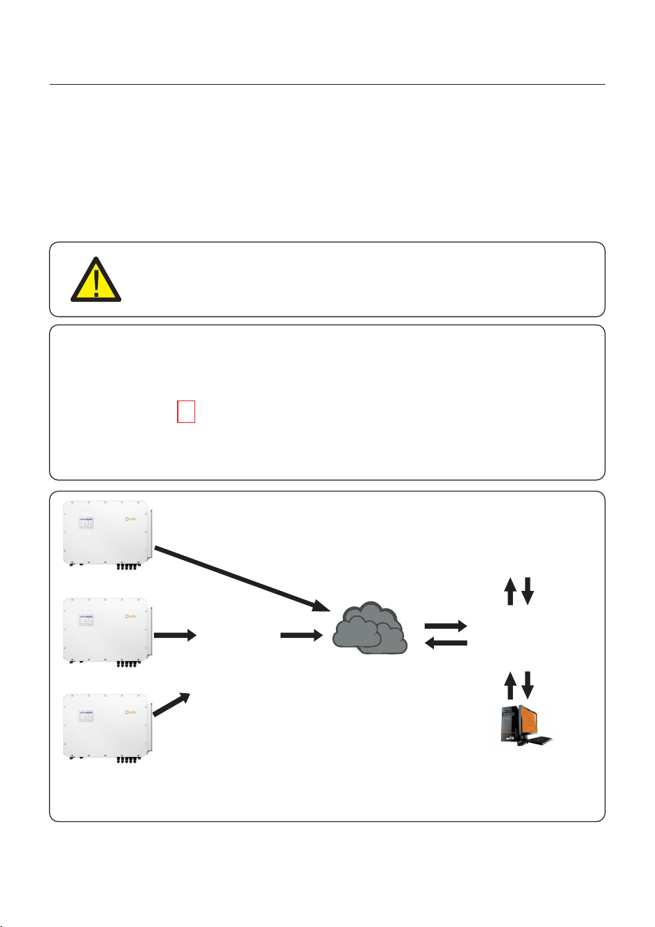
LAN monitoring
The inverter can be remotely monitored via WiFi, LAN or 4G.
The USB type COM port at the bottom of the inverter can connect to different kinds of Solis
data loggers to realize the remote monitoring on Soliscloud platform.
To install Solis data loggers, please refer to corresponding user manuals of Solis data loggers.
The Solis data loggers are optional and can be purchased separately.
Dust cover is provided the inverter package in case the port is not used.
WARNING:
The USB type COM port is only allowed to connect Solis data loggers.
It is forbidden to be used for other purposes.
4G monitoring
WiFi monitoring
Router
Internet
Web server
Figure 3.23 Wireless communication function
Soliscloud
APP
3.14 Inverter Remote Monitoring Connection
40
User Manual
4. Overview
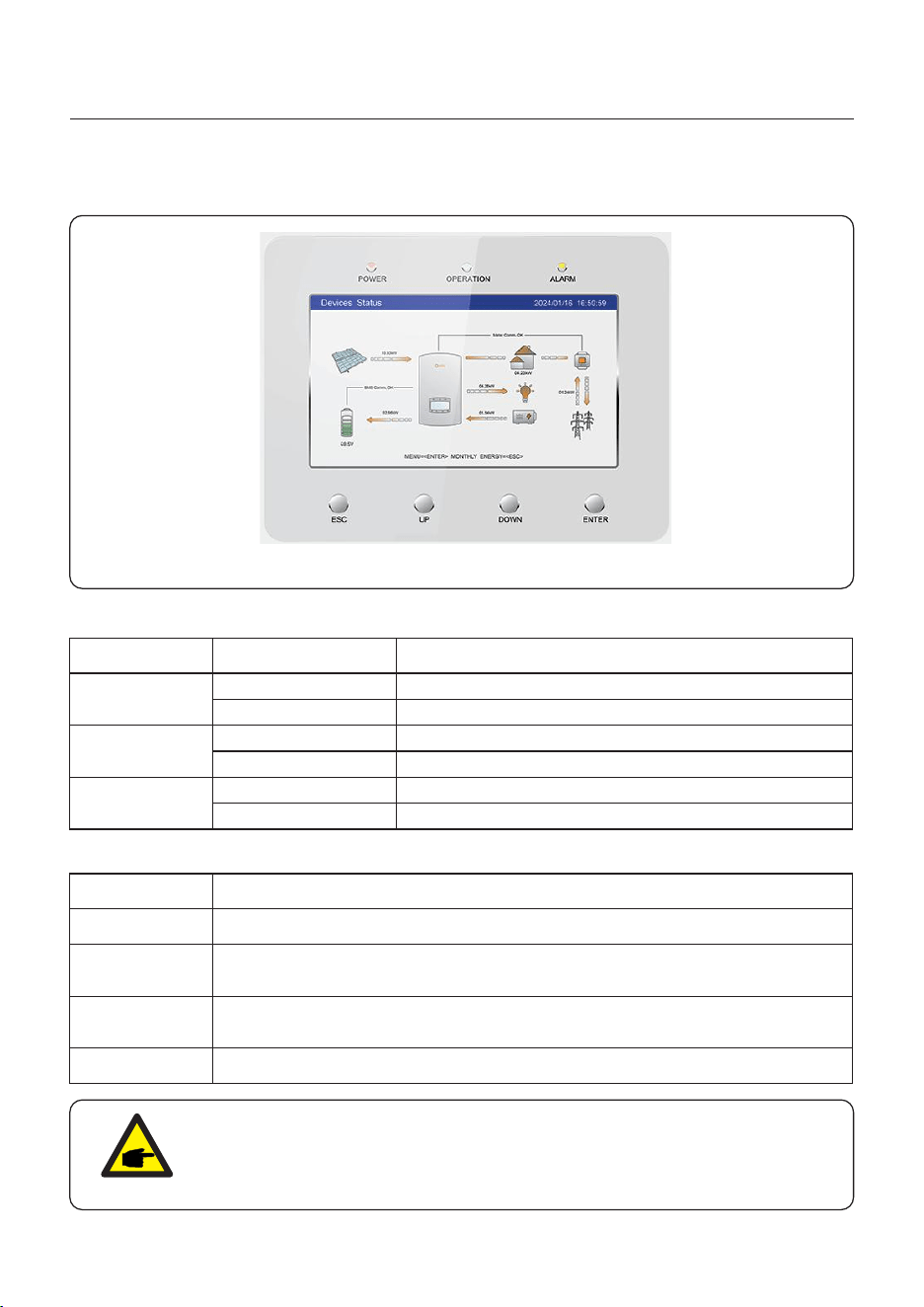
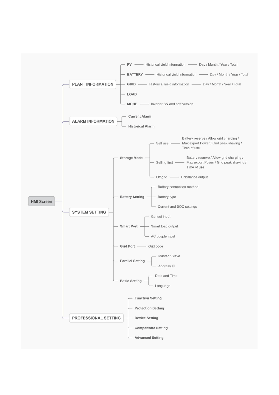
4.1 HMI Screen
There are 3 indicators and 4 operation button on the Solis S6 Series Inverter.
41
Indicators Status
POWER
Red light solid on
OPERATION
Green light solid on
ALARM
Yellow light solid on
OFF
OFF
OFF
Description
Normally powering
Not working
Normally powering
No operation
Alarm
Normal
Button
ESC
UP
DOWN
Description
“Escape”, allows the user to exit, or cancel the operation.
Upwards key, allows the user to increase the value or move forward to the
next option.
Downwards key, allows the user to decrease the value or move backward
to the previous option.
ENTER Running or executing command .
NOTE:
The screen will be automatically turn off after being idle for a few minutes to
save power, click any operation button(“ESC”/“UP”/“DOWN”/ “ENTER”) to
restart the screen, then press“Enter”into the main operation interface.
Description of indicators:
Description of buttons:

User Manual
4. Overview
42
4.2 Inverter built-in Bluetooth description
Blueooth: BDR、EDR、BLE
frequency band(s) in which the radio equipment operates:2.402-2.480GHZ
Maximum transmitting power: 8dBm
Hereby, Ginlong Technologies Co.,Ltd.declares that the radio equipment type hybrid
inverter is in compliance with Directive 2014/53/EU
43
5. Commissioning
User Manual
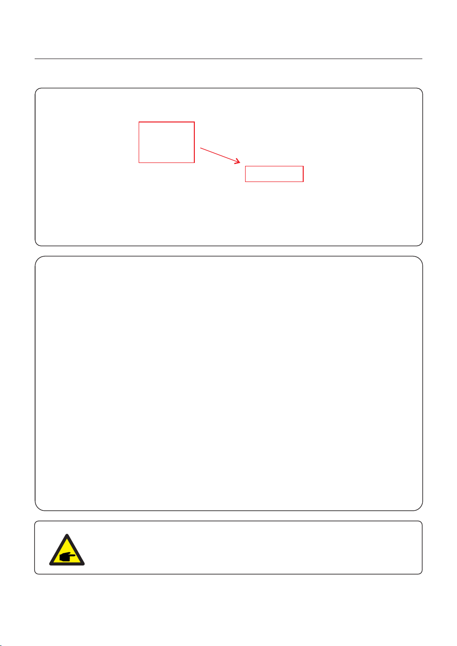
5.1 Pre-Commissioning
+
-
Measure DC voltage of
PV strings and battery
Measure AC voltage
and frequency
● Make sure that no high voltage conductors are energized.
● Check all conduit and cable connection points ensure they are tight.
● Verify that all system components have adequate space for ventilation.
● Follow each cable to ensure that they are all terminated in the proper places.
● Ensure that all warning signs and labels are affixed on the system equipment.
● Verify that the inverter is secured to the wall and is not loose or wobbly.
● Prepare a multimeter that can do both AC and DC amps.
● Have an Android or Apple mobile phone with Bluetooth capability.
● Install the Soliscloud APP on the mobile phone and register a new account.
● There are three ways to download and install the latest APP.
1. You can visit www.soliscloud.com.
2. You can search”Soliscloud”in Google Play or APP Store.
3. You can scan this QR code to download Soliscloud.
5.2 Power ON
Step 1: With the DC switch off, energize the PV strings and then measure DC voltage of the
PV strings to verify that the voltage and polarity are correct. Turn on the battery and check
the battery voltage and polarity as well.
Step 2: Turn on the OCPD for the system and then measure the AC voltages line to line
and line to neutral. The backup side of the system will be off until commissioning is complete.
Turn the OCPD back off for now.
Step 3: Turn the DC switch on and then the OCPD(AC breaker) for the system.
This inverter can be powered on by PV only, battery only and Grid only.
When the inverter is powered on,the five indicators will be lighted at once.
5.3 Power OFF
Step 1: Turn off the AC breaker or AC disconnect switch to disable AC power to the inverter.
Step 2: Turn off the DC switch of the inverter.
Step 3: Turn off the battery breaker.
Step 4: Use a multimeter to verify that the battery and AC voltages are 0V.
If this is the first time the inverter has been commissioned, you will need to first go through
the Quick Settings. Once this has been done, these settings can be changed later.
Inverter Time -> Meter Setting -> Grid Code -> Storage mode -> Battery Model
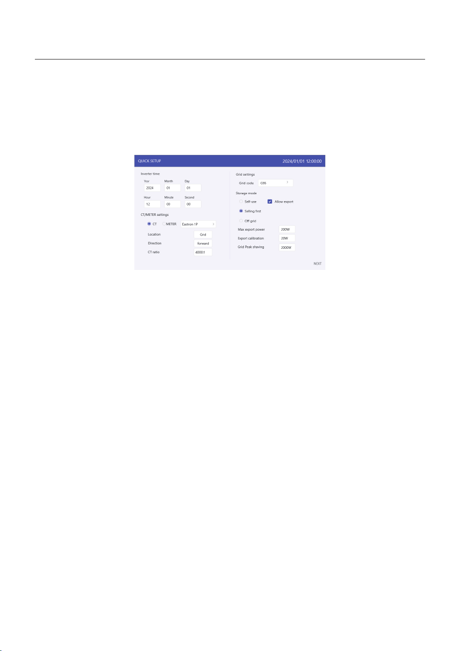
5.4 HMI Screen Setting
5. Commissioning
User Manual
44
1. Inverter time:
Set inverter time and date, default follow the phone.
2. CT/Meter setting:
Select the CT or Meter, Solis provide Eastron 3 phase meter, it is self-identifiable.
Set installation location: Grid side / Load side / Grid+PV inverter;
CT direction: When CT installed correctly, select “Forward”; when CT installed direction
wrong, the sampling current of CT will be reversed when calculating the power, select
“Reversal” to correct it.
Set CT ratio: default 120 (Solis provide AKH-0.66-K-80*40-600A), if the user install
their own CT, then need to set the CT ratio manually. If the system connected to Meter,
then CT ratio need to be set on Meter.
3. Grid code:
Select grid code that meet the local regulations.
4. Storage mode:
ALL modes first priority is to use the available PV power to support loads. The different
modes determine what the second priority, or use of the excess PV power, will be.
Self-use / Selling first / Off-grid are exclusive, the user could select only one mode.
5.4.1 HMI Quick Setting
5. Commissioning
User Manual
45
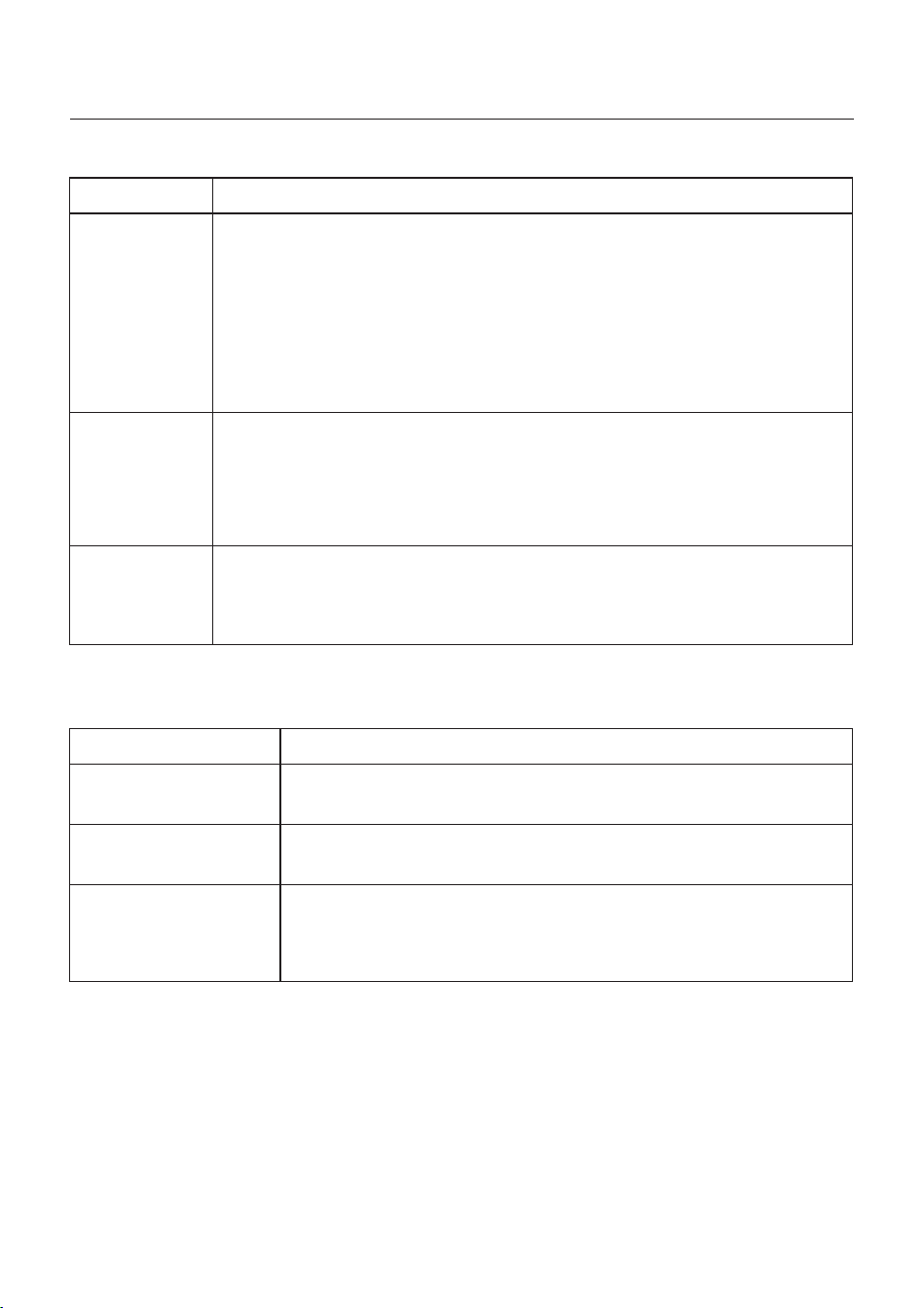
Mode
Self-use
Selling first
Off grid
Description
PV power flow priority sequence: loads > battery > grid.
In this mode, the system stores excess PV power into the battery after
the loads are supplied.
If “Allow export” turned on, when the battery is charged full, or there is no
battery, the excess PV power will be exported(sold)back to the grid.
If the system is set to not export any power, then the inverter will curtail
the PV power (derate the inverter output power).
PV power flow priority sequence: loads > grid > battery.
In this mode, the system exports any excess PV power after the loads
are supplied. If the export power quota has been met, then the remaining
PV power will be stored in the battery.
Notice: This mode should not be used if export power set to zero.
PV power flow priority sequence: loads> battery.
This mode only used when the system are not electrically connected to
the grid at all. This mode is like Self-Use Mode, but the PV power will be
curtailed if the PV power output is> battery power + load power
Table 1 Description of modes
Under each mode, user could set other functions based on their requirements.
Settings
Max export power
Export calibration
Grid peak shaving
Description
Default: 1.1 times of rated power.
Notice: if feed-in is not allowed, set Max export power to 0.
Range : -500w-500w, default 20w, settable.
To compensate the deviation of CT/Meter in practical application.
Default enable, default 2 times of rated power.
Limit the power drawn from the grid to prevent from exceeding
regulatory requirements or the power line capacity.
It works only when the “battery reserve” turned on.
Table 2 Description of mode settings

5. Commissioning
User Manual
46
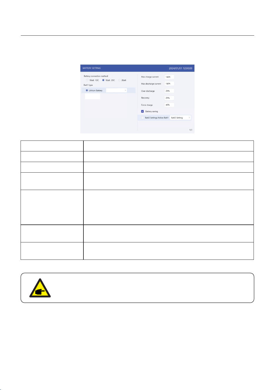
5. Battery setting:
Select Battery connection method:1 Batt 1 DC / 1 Batt 2 DC / 2 Batt 1 DC; the connection
method please refer to 3.13 Lithium battery wiring.
Select battery brand (if the connected battery is not on the list, please select
“General_LiBat_HV”).
Set Max charging/discharging current.
If there are two batteries and share the same settings, please tick the box of “Batt2 Settings
follow Batt 1”.
5. Commissioning
User Manual
47
5.4.2 HMI screen operation system overview
5. Commissioning
User Manual
48
5.4.3 Detailed HMI Setting
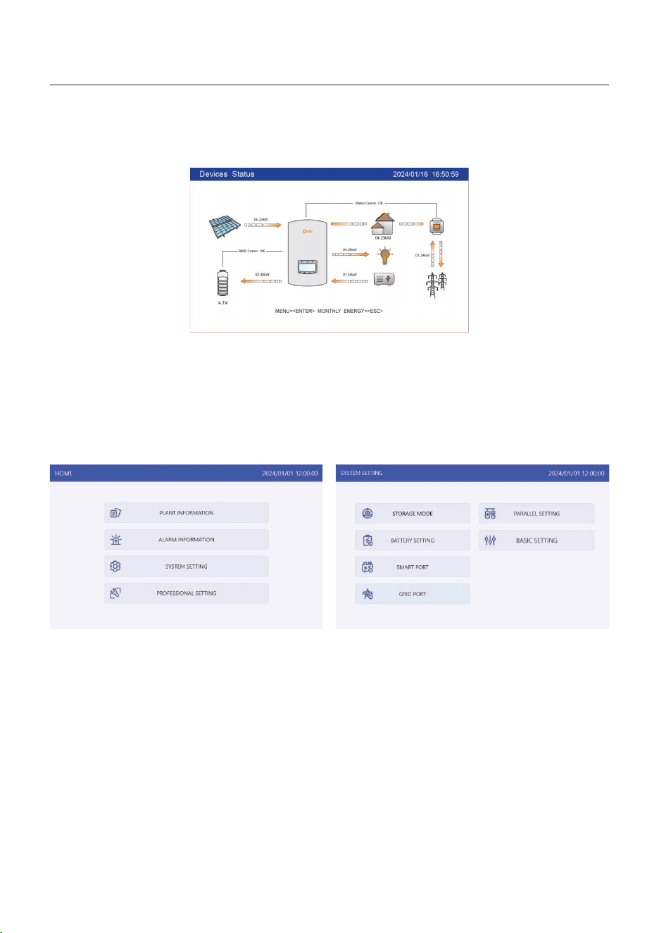
Step 1: Enter Home page
After quick setting, press “ENTER”, the screen displays the home page.
The screen will be automatically turn off after being idle for a few minutes to save power,
click any operation button(“ESC”/”UP”/”DOWN”/ “ENTER”) to restart the screen, then press
“Enter” into the main operation interface.
Step 2: Enter “SYSTEM SETTING” interface
Press“Down” button, then press “ENTER” into the “SYSTEM SETTING” interface.
5. Commissioning
User Manual
49
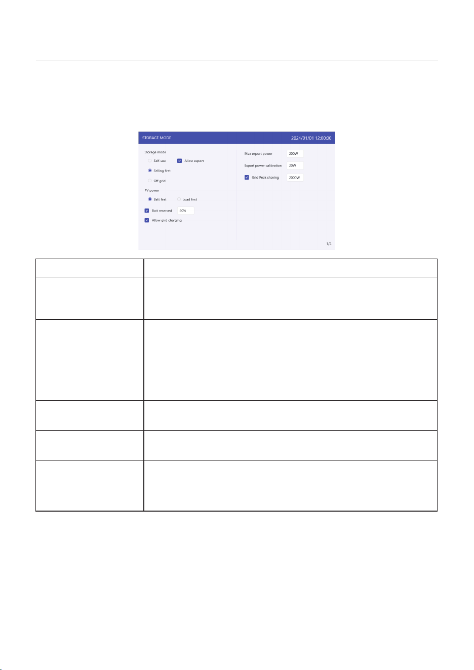
Step 3: Set “Storage Mode”
Use “UP” or “DOWN” key to select the desired mode, then press “ENTER”.
The Mode description please refer to 5.4.1.
Settings
Battery reserve
Allow grid charging
Max export power
Export calibration
Grid peak shaving
Description
Range: 5~95%, default: 80%, settable.
When battery SOC < set battery reserve SOC, battery will stop
discharging.
Allow grid charging the battery when it enables.
Notice: if “Allow Grid Charging” is turned on, the inverter will use
grid power to charge the battery only under two circumstances:
The battery drains to the Force Charge SOC.
When PV power output can’t meet the set current value during
the charge periods.
Default: 1.1 times of rated power.
Notice: if feed-in is not allowed, set Max export power to 0.
Range : -500w-500w, default 20w, settable.
To compensate the deviation of CT/Meter in practical application.
Default enable, default 2 times of rated power.
Limit the power drawn from the grid to prevent from exceeding
regulatory requirements or the power line capacity.
It works only when the “battery reserve” turned on.
Table 3 Description of storage mode settings
50
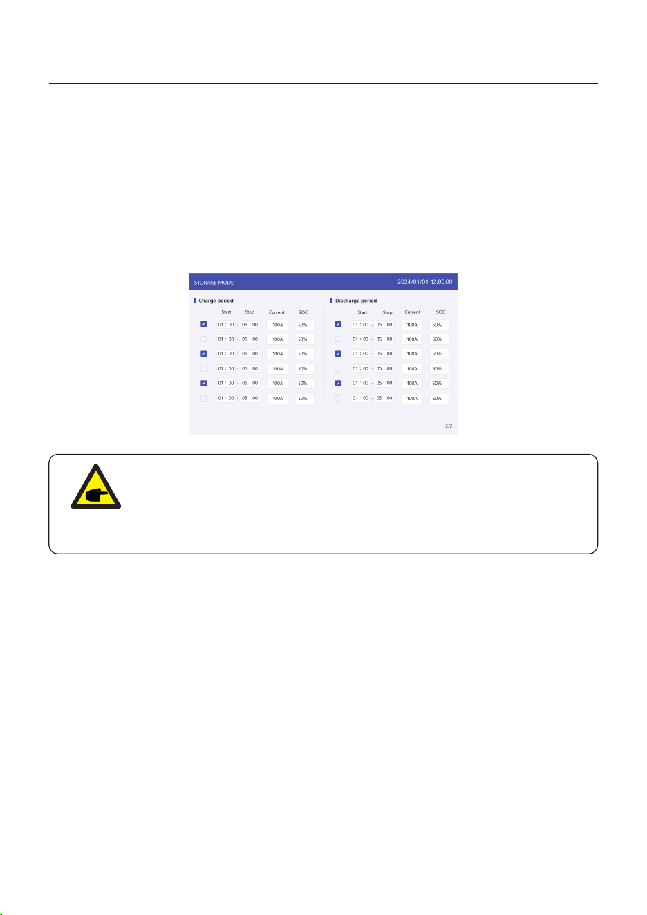
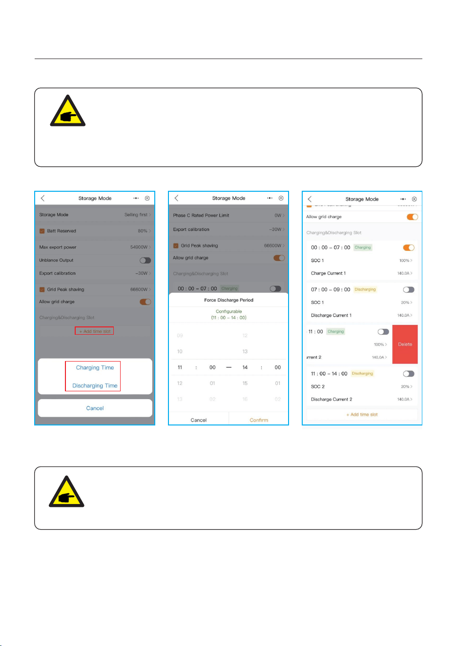
Step 4: Set “Time of use” under each mode (Skip this step if no need)
Time of Use is for manual control of the battery charging/discharging. It is for customizing
when the battery is allowed to charge and discharge power and at what rate, established by
a current(amperage)setting.
1. Charge period: battery charges with set current value until the charging cut-off voltage
(settable), checking the box to control whether enable this charging period.
2. Discharge period: battery discharges with set current value until the discharging cut-off
voltage (settable), checking the box to control whether enable this discharging period.
5. Commissioning
User Manual
NOTE:
The set current value is the maximum current for charging/discharging the
battery. However, the actual charging and discharging current may not reach
this value due to the influence of other factors, such as the maximum charging/
discharging power limitation of the inverter, the battery BMS limitation, etc.
5. Commissioning
User Manual
51
Step 5: Set “Battery Setting”
PYLON_HV
Settings
Max charge current
Max discharge current
Over discharge
Recovery
Force charge
Max charge SOC
Description
Max charge current, settable.
Max discharge current, settable.
Range: 5~40%, default 20%,
when battery SOC < over discharge, it will stop discharging.
Range: set Over discharge value +1% ~ set Over discharge
value +20%;
The battery can discharge when the SOC/Voltage reaches the
set value. Avoid repeated changes in the charging and
discharging status of the battery.
The battery will be charged to the over discharge SOC/Voltage
when it reaches this setting.
The maximum SOC/Voltage that the battery can be charged to.
Default 100%.
Table 4 Description of battery mode settings
NOTICE:
Force charge SOC < Over discharge SOC < Recovery SOC, otherwise the
setting might be error.
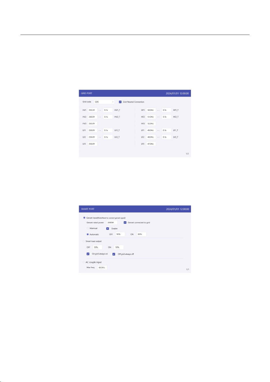
Step 6: Set “Grid Port”
(Skip this step if grid code is already set in quick setting)
Select grid code that meet the local regulations.
Three level of Over-voltage / under-voltage / Over-frequency / under-frequency are default
based on grid code, there is no need to set the parameters in manual.
5. Commissioning
User Manual
52
Step 7: Set “Smart Port”
(Skip this step if the system is not connected to generators)
When it is connected to Generator, select “Gunset input”;
When it is connected to smart load like heat pump,select “Smart load output”
When it is connected to Grid-tied inverter,select “AC coupled”
Genset
The user need to input the “Genset rated power” by manual.
OFF: Generator stops charging SOC, settable, range:35~100%;
ON: Generator start charging SOC; settable, range:1~95%;
AC coupled:
Max Freq: Grid-tied inverter stops charging frequency, settable,
If grid Level 1 over-frequency threshold <55Hz,
Range: Level 1 over-frequency threshold~ Level 1 over-frequency threshold+ 0.1Hz~54Hz;
If grid Level 1 over-frequency threshold <65Hz,
Range: Level 1 over-frequency threshold~ Level 1 over-frequency threshold+ 0.1Hz~65Hz;

5. Commissioning
User Manual
53
Step 8: Set parallel system
Set Master and Slave machine,
Set Master ID as: 1
Slave machine ID as: 2
.Slave machine ID as: 3
..... and so on.
5. Commissioning
User Manual
54
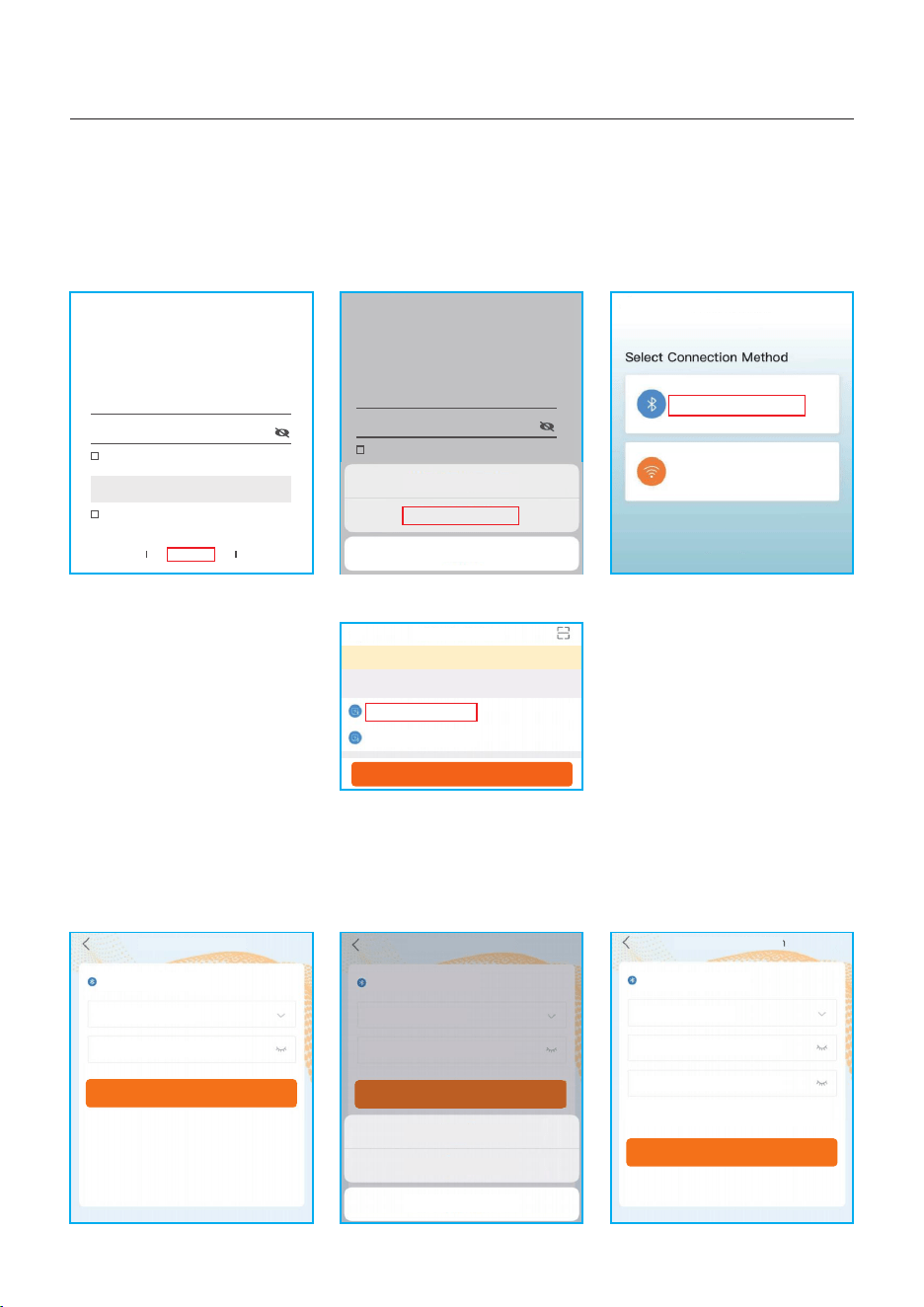
Step 1: Connect with Bluetooth.
Turn on Bluetooth switch on your mobile phone and then open the Soliscloud APP.
Click “More Tools”->”Local Operation”->”Connect with Bluetooth”
Step 2: Select the Bluetooth signal from the inverter. (Bluetooth Name: Inverter SN)
Step 3: Login account.
If you are the installer, please select the account type as Installer. If you are the
plant owner, please select the account type as owner. Then set your own initial password
for control verification. (The first log-in must be finished by installer in order to do the
initial set up)
Hello,
Welcome to SolisCloud
Register
Username/Email
Password
I have agreed Privacy Policy
Remember Forgot Password
Language More Tools Data Migration
Log in
Local Operation
Connect With Bluetooth
Connect With WiFi
<
xxxxxxxxxxxx
Nearby Device
<
vivo TWS 2
<
<
Search Device
If the dev ic e is not in the list, please cl ic k th e “Search Device”
button a t th e bottom or drop-down to re fr es h the page
Other Device
xxxxxxxxxxxx
Control Verification
Select account type
Enter password (6-characters)
Verify
<
xxxxxxxxxxxx
Control Verification
Installer
Enter password (6-characters)
Enter password again
Please set the password of the installer’s account
before continuing
Set Enable
<
xxxxxxxxxxxx
Control Verification
Select account type
Enter password (6-characters)
Verify
Installer
Owner
Cancel
<
5.5 APP Setting
5.5.1 Log in the APP via Bluetooth
Hello,
Welcome to SolisCloud
Register
Username/Email
Password
I have agreed Privacy Policy
Remember Forgot Password
Log in
WiFi Configuration
Local Operation
Cancel
5. Commissioning
User Manual
55
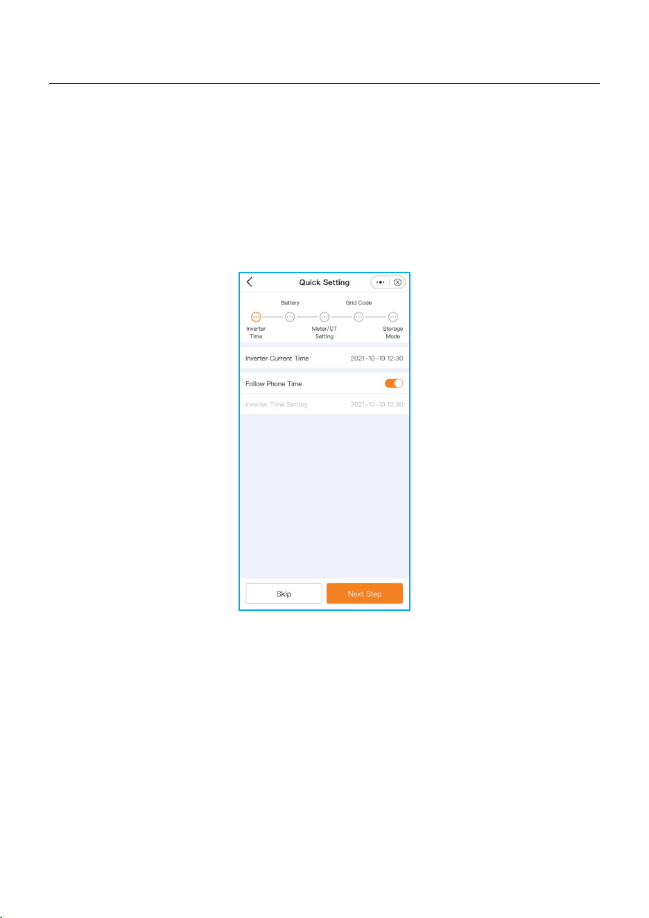
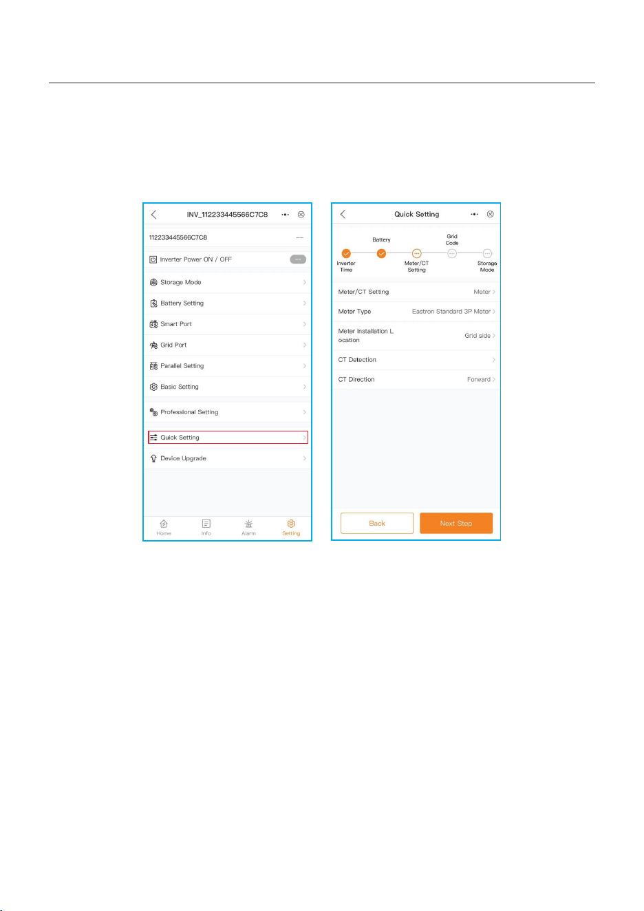
5.5.2 APP Quick Setting
If this is the first time the inverter has been commissioned, you will need to first go through
the Quick Settings. Once this has been done, these settings can be changed later.
Inverter Time -> Meter Setting -> Grid Code -> Storage mode -> Battery Model
(1)Inverter time:
Set inverter time and date, tap the slider next to “Follow Phone Time”, then tap “Next step”
at the bottom right corner.
5. Commissioning
User Manual
56
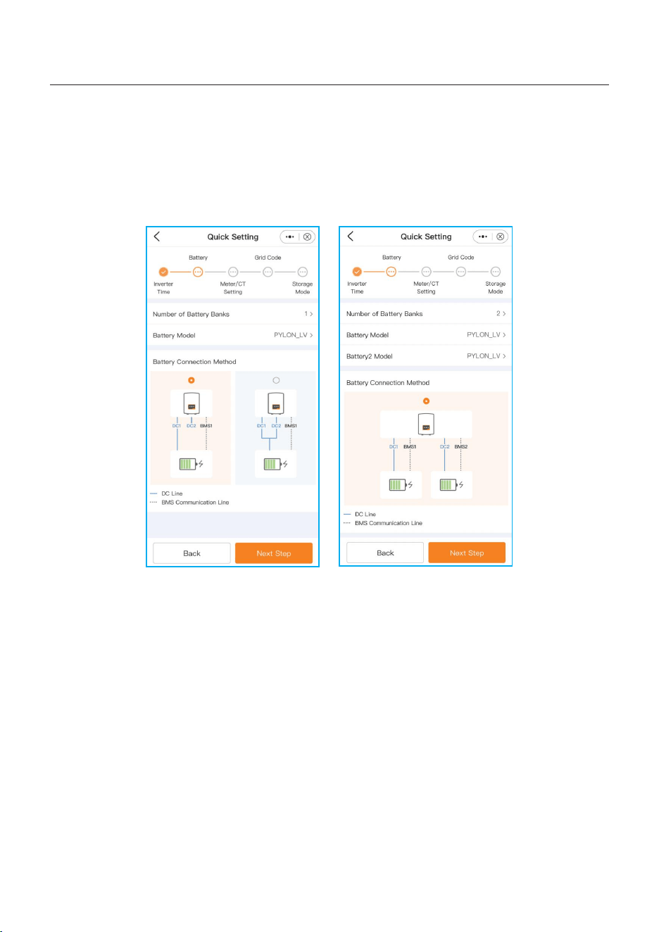
(2)Battery:
•Select number of battery banks :1-2;
•Select battery model: if the connected battery brand is not on the list, please select
“General_LiBat_HV
•Select battery connection method.
5. Commissioning
User Manual
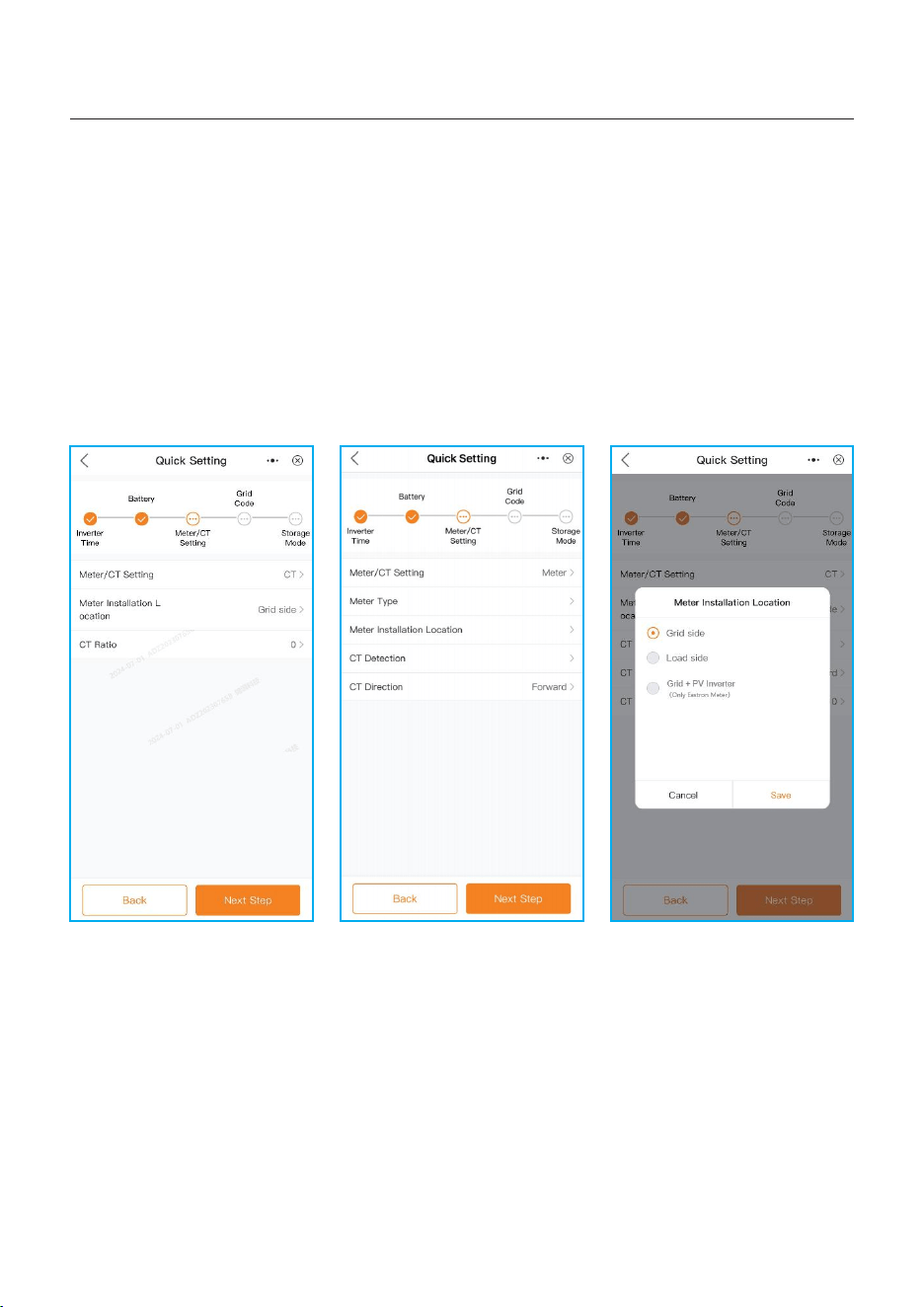
(3)CT/Meter setting:
•Select CT or Meter;
•Set Meter type (Solis provide Eastron 3 phase meter, it is self-identifiable).
•Set Meter installation location: Grid side / Load side / Grid+PV inverter;
•Set CT ratio: default 60 (Solis provide ESCT-T50-300A/5A CT), if the user install their own
CT, then need to set the CT ratio manually. If the system connected to Meter, then CT ratio
need to be set on Meter.
•CT direction: When CT installed correctly, select “Forward”; when CT installed direction
wrong, the sampling current of CT will be reversed when calculating the power, select
“Reversal” to correct it.
57
5. Commissioning
User Manual
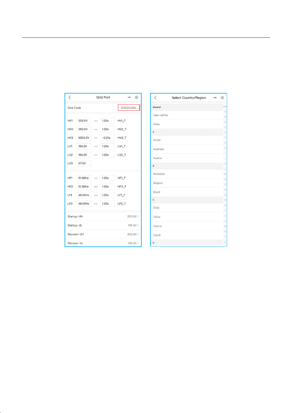
(4)Grid code:
Select grid code that meet the local regulations.
Three level of Over-voltage / under-voltage / Over-frequency / under-frequency are default
based on grid code, there is no need to set the parameters in manual.
58
5. Commissioning
User Manual
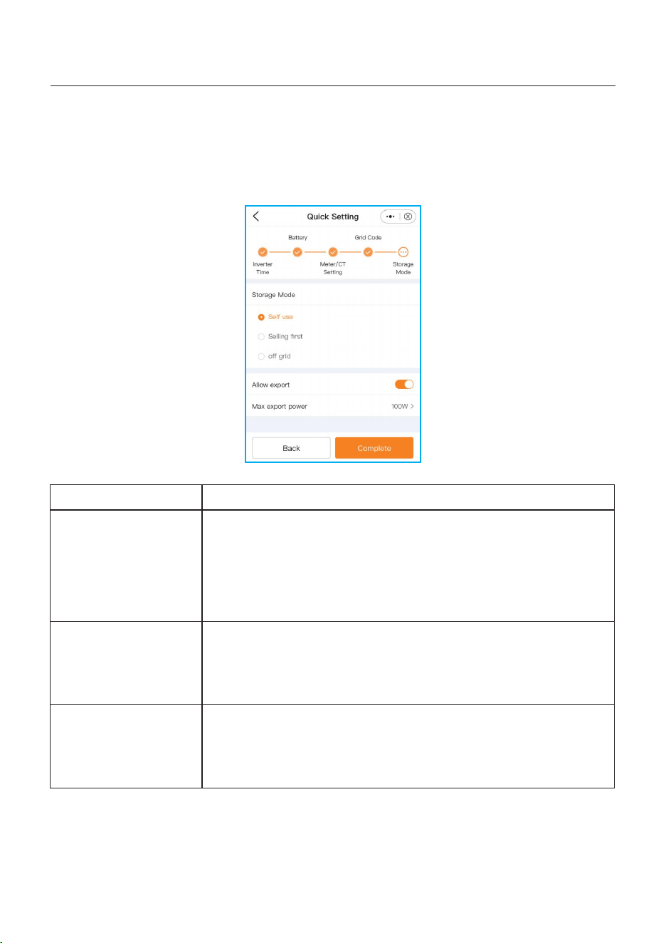
(5)Storage mode:
ALL modes first priority is to use the available PV power to support loads. The different
modes determine what the second priority, or use of the excess PV power, will be.
Self-use / Selling first / Off-grid are exclusive, the user could select only one mode.
Settings
Self-use
Selling first
Off grid
Description
PV power flow priority sequence: loads > battery > grid.
In this mode, the system stores excess PV power into the battery
after the loads are supplied. If the battery is charged full, or there
is no battery, the excess PV power will be exported(sold)back to
the grid.
If the system is set to not export any power, then the inverter will
curtail the PV power (derate the inverter output power).
PV power flow priority sequence: loads > grid > battery.
In this mode, the system exports any excess PV power after the
loads are supplied. If the export power quota has been met, then
the remaining PV power will be stored in the battery.
Notice: This mode should not be used if export power set to zero.
PV power flow priority sequence: loads > battery.
This mode only used when the system are not electrically
connected to the grid at all. This mode is like Self-Use Mode,
but the PV power will be curtailed if the PV power output is >
battery power + load power.
Table 5 Description of Storage modes
Once quick setting finished, tap “Complete”, the APP enter the homepage.
59
5. Commissioning
User Manual
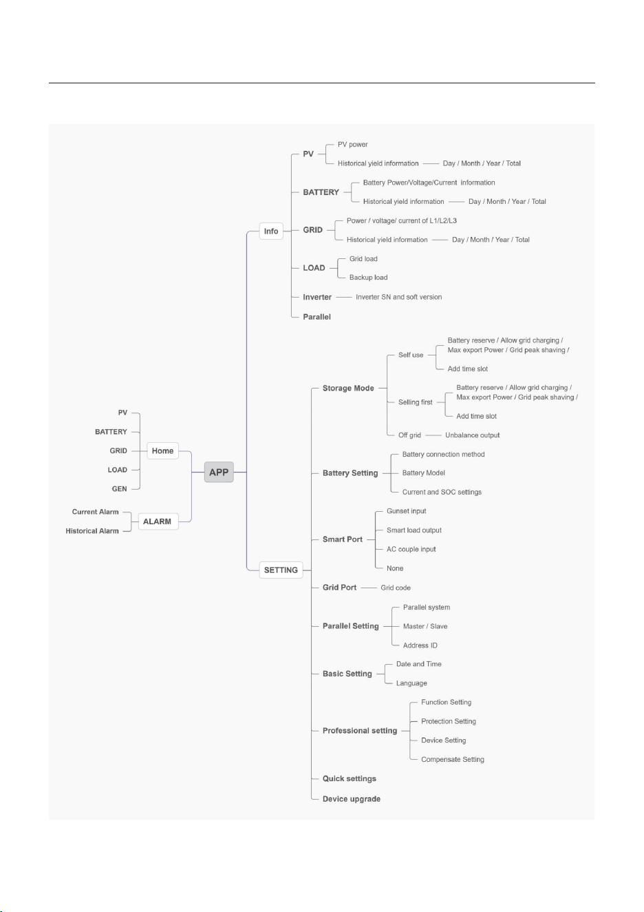
5.5.3 APP interface structure
60
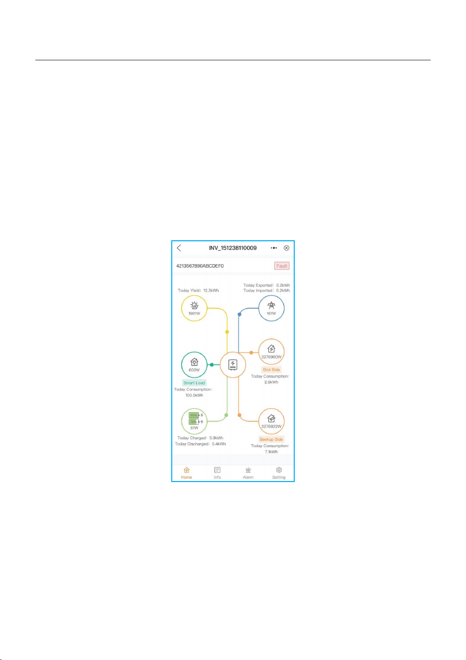
This screen display energy production and consumption, as well as its flow. It shows the
following data:
•Today yield of PV
•Today Imported/Exported of Grid
•Today Charged/Discharged of Battery
•Today Consumption of Grid-side load
•Today Consumption of Back-up load
•Today GEN yield.
5.5.4 Home
5. Commissioning
User Manual
At the bottom of page are four sub menus: Home, Info, Alarm and Settings.
61
Under this page, the user could find quick setting and other detailed settings as follows:
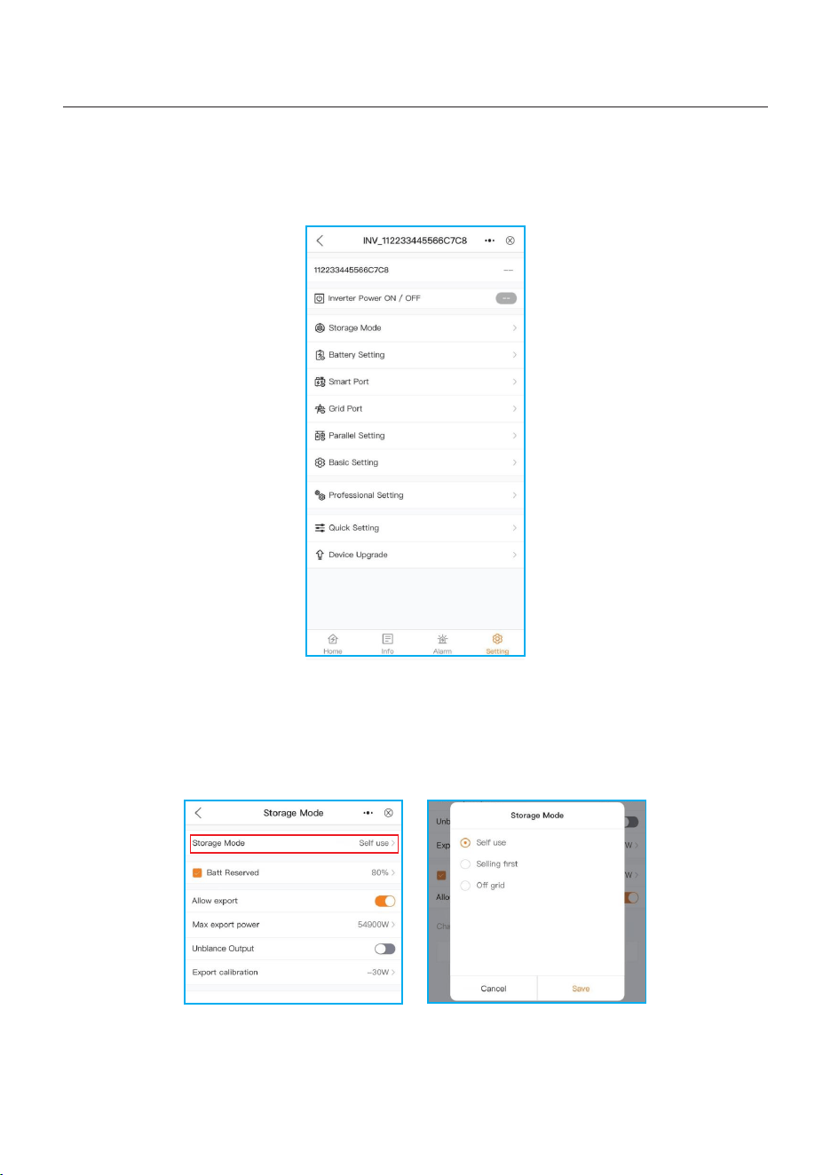
5.5.5 Setting
5. Commissioning
User Manual
1. Storage mode
a. Select storage mode:
•Self-use / Selling first / Off-grid, these three modes are exclusive, the user could select only
one mode. The modes definition could refer to 5.5.2“Quick setting”
•The Mode description please refer to 5.4.1.
62
5. Commissioning
User Manual
Please notice:
“Allow export" can only be set in “Self use” mode;
“Add time slot” can only be set in grid-connected mode (Self use” mode and “ Selling first”
mode).
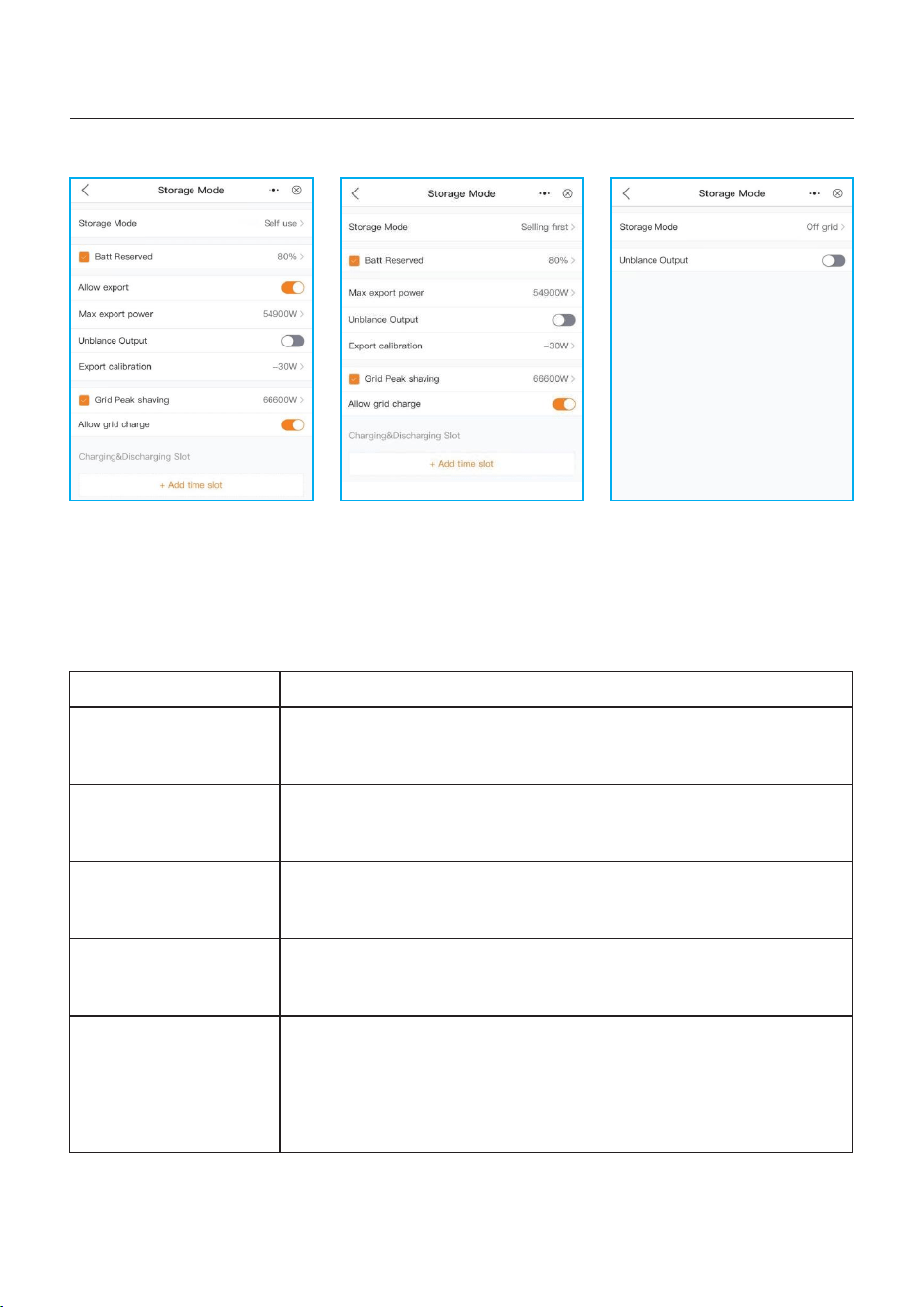
b. Set mode operations:
Settings
Battery reserved
Allow export
Max export power
Export calibration
Allow grid charging
Description
Range: 5~95%, default:80%, settable.
When battery SOC < set battery reserve SOC, battery will stop
discharging.
When it enables, the system is allowed to export power to grid.
Default: 1.1 times of rated power.
Notice: If feed-in is not allowed, set Max export power to 0.
Range : -500w-500w, default 20w, settable.
To compensate the deviation of CT/Meter in practical application.
Allow grid charging the battery when it enables.
Notice: if “Allow Grid Charging” is turned on, the inverter will use
grid power to charge the battery only under two circumstances:
•The battery drains to the Force Charge SOC.
•When PV power output can’t meet the set current value during
the charge periods.
Table 6 Set mode operations
63
5. Commissioning
User Manual
Charge SOC: battery charging stops when reach the set SOC;
Discharge SOC: battery discharging stops when reach the set SOC.
NOTICE:
•Slide the switch to on, the battery charge/discharge with set charge/
discharge current by following the set period
•Slide to the left of screen, the user could delete the current period setting.
64
c. Add time slot:
NOTE:
Solis's export power control function is based on the sampling results from the
smart meter or smart CT. Due to the sampling interval limitation, when the
system's load consumption has sudden changes, small amount of export
overshooting is expected. For strict zero injection applications, it is suggested
to install external backflow trip device as additional protection for injection.
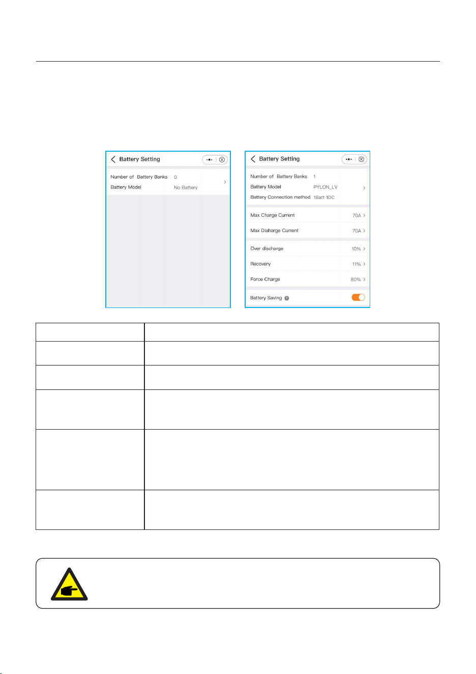
2. Battery setting
a. Set “ Number of Battery Banks” and “Battery Model”
b. Set “Battery Connection Method” : 1 Batt 1 DC / 1 Batt 2 DC / 2 Batt 1 DC;
c. Set battery parameters
5. Commissioning
User Manual
Settings
Max charge current
Max discharge current
Description
Max charge current, settable.
Range : 5~40%, default 20%,
when battery SOC < over discharge, it will stop discharging.
Range : set Over discharge value +1% ~ set Over discharge
value +20%;
Battery won't stop charging until it reaches Recovery SOC value,
reserve the return difference value to avoid the battery
repeatedly cross jump between charging and discharging.
Table 7 Battery setting
Max discharge current, settable.
Force charge
Range : 4%~ set Over discharge value,
when battery SOC < force charge SOC, the grid will charge the
battery.
NOTICE:
Force charge SOC < Over discharge SOC < Recovery SOC, otherwise the
setting might be error.
65
Over discharge
Recovery
5. Commissioning
User Manual
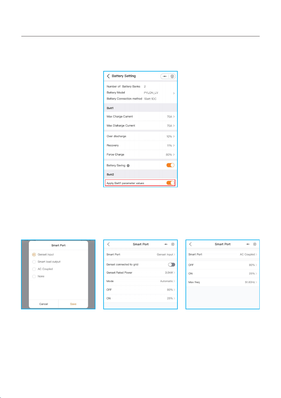
d. If two battery banks share the same setting, then turn the “Apply Batt1 parameter values”
on. It will match the settings of battery bank 1 automatically.
3. Smart port
Select smart port type
•When it is connected to Generator, select “Gunset input”;
•When it is connected to smart load like heat pump,select “Smart load output”
•When it is connected to Grid-tied inverter, select “AC coupled”
Genset Rated Power: manual input.
OFF: Generator stops charging SOC, settable, range:35~100%;
ON:Generator start charging SOC; settable, range:1~95%;
AC coupled:
OFF: Grid-tied inverter stops charging SOC, settable, range:35~100%;
ON: Grid-tied inverter start charging SOC; settable, range:1~95%;
66
5. Commissioning
User Manual
4. Grid port
Please refer to “5.5.2 APP Quick setting”
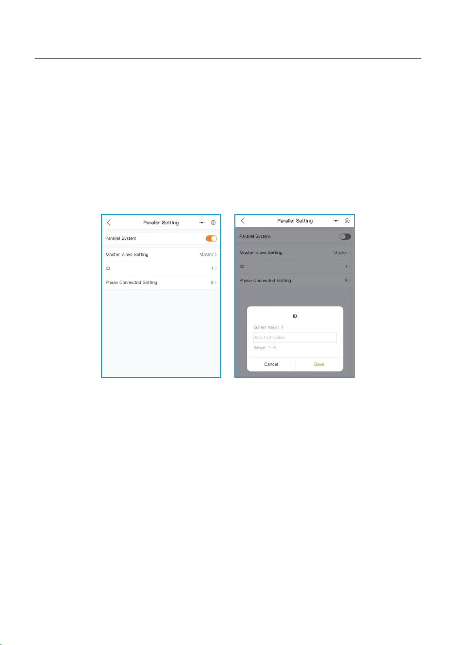
5. Parallel setting
When there are ≥ 2 inverters in parallel, turn the slider on
Set Master and Slave machine,
Set Master ID as: 1
Slave machine ID as: 2
.Slave machine ID as: 3
..... and so on.
6. Basic setting
Set inverter time and date, tap the slider next to “Follow Phone Time”, then tap “Save”.
67
5. Commissioning
User Manual
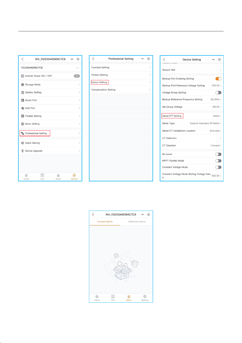
7. CT/Meter setting
There are two ways for CT/Meter setting, detailed setting please refer to “5.5.2 APP Quick
setting”.
Method 1: Quick setting
68
5. Commissioning
User Manual
Method 2: Setting --- Professional Setting -- Device Setting --Meter/CT Setting
The alarm page can display the current alarm and the historical alarms.
5.5.6 Alarm
69
5. Commissioning
User Manual
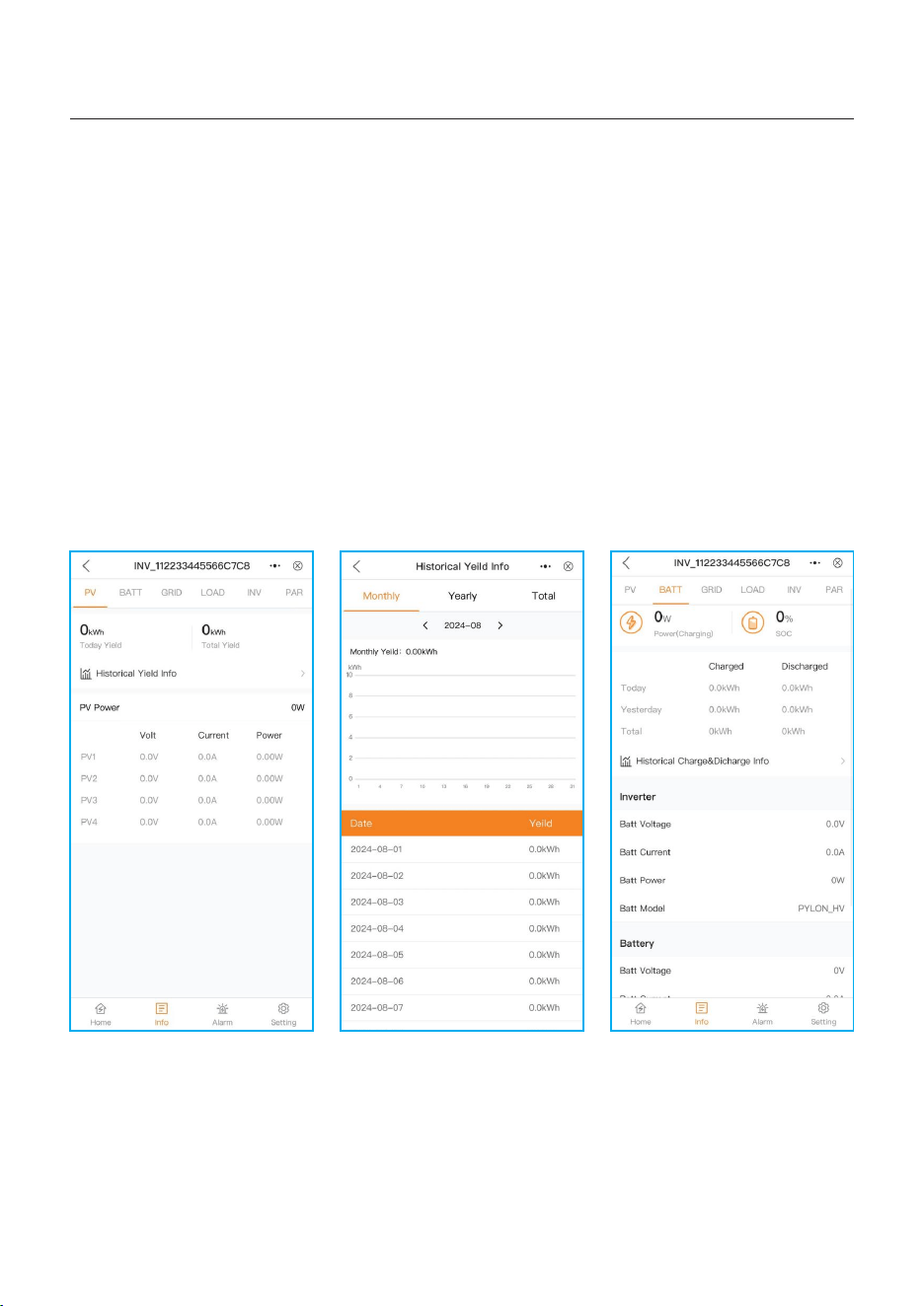
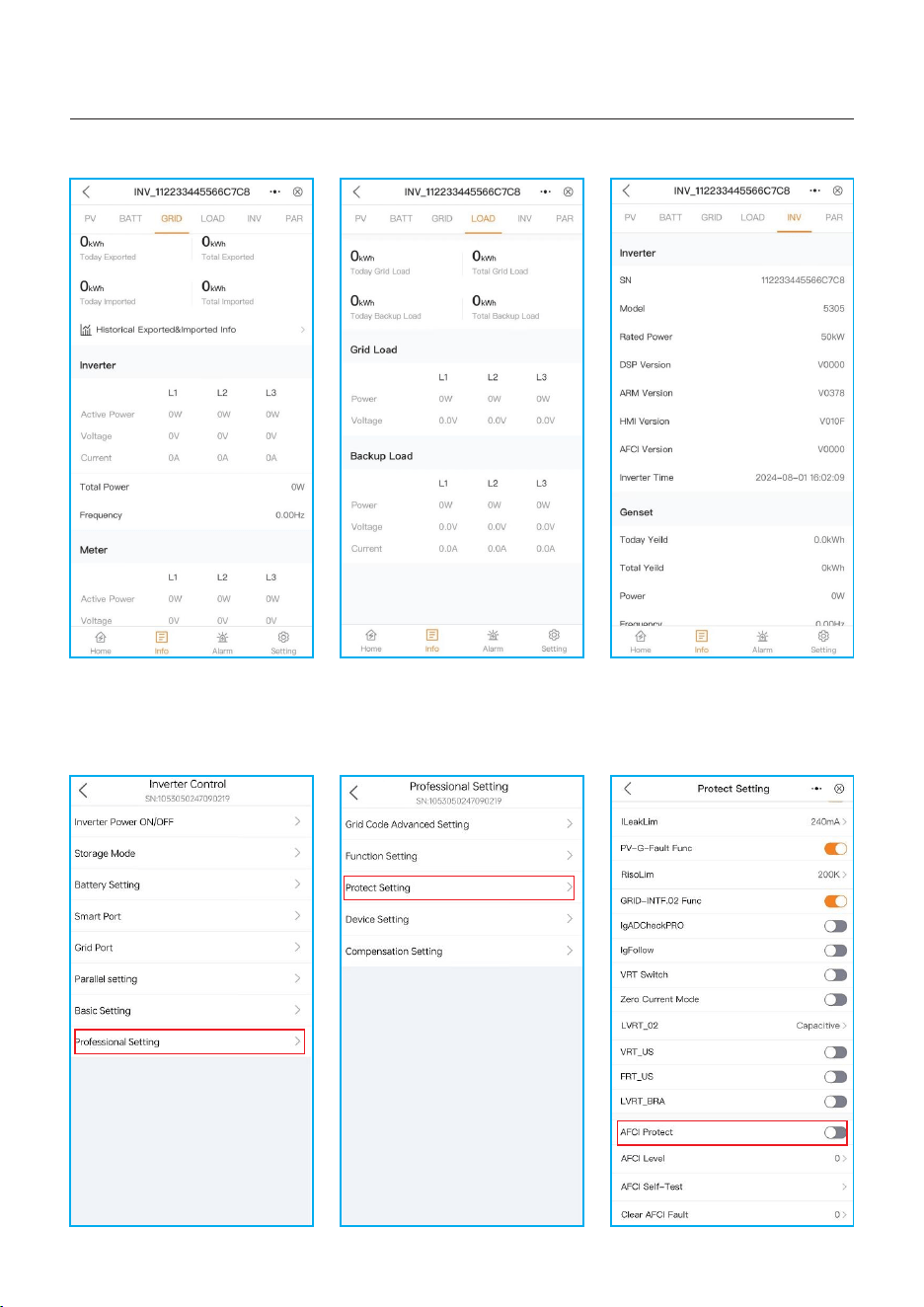
The use could Query information of PV / Battery / GRID / LOAD / INVERTER.
PV : it display each PV module Power/Voltage/Current, as well as historical yield information
calculated by monthly / yearly / total, displayed with graphics;
BATT: it display battery Power/Voltage/Current/SOC/SOH/Max.charging current /
Max.discharging current, as well as historical battery charging and discharging information
calculated by monthly / yearly / total, displayed with graphics;
GRID: it display Active power / voltage/ current of L1/L2/L3, as well as historical exported/
imported information calculated by monthly / yearly / total, displayed with graphics;
LOAD: it displays power/voltage of grid load, power/voltage/current of backup load;
INV: it displays inverter SN/model number, and software version.
5.5.7 Information
70
5. Commissioning
User Manual
71
If you want to enable AFCI function for your inverter, just using the Solis APP and follow the
below procedure: Professional Setting —> Protect Setting —> AFCI Protect
5.5.8 How to enable AFCI function
NOTE:
Never use any solvents, abrasives, or corrosive materials to clean the inverter.
CAUTION:
Do not touch the surface when the inverter is operating. Some parts may be
hot and could cause burns. Turn OFF the inverter and let it cool down before
you do any maintenance or cleaning of inverter.
Solis S6 Series inverter does not require any regular maintenance. However, cleaning the
heatsink will help the inverter dissipate heat and increase the lifetime of inverter. The dirt on the
inverter can be cleaned with a soft brush.
The Screen and the LED status indicator lights can be cleaned with cloth if they are
too dirty to be read.
User Manual
6. Maintenance
6.1 Smart O&M
In order to improve our products and provide you with higher quality services, this device
has a built-in data logging module for collecting relevant information during operation
(such as power generation data, fault data)
Commitment:
1. We will only collect, use and process your device information for the purpose of
improving our products and services.
2. We will take all reasonable and feasible measures to ensure that no irrelevant
information is collected and we will protect your device information.
3. We will not share, transfer or disclose the collected device information with any
company, organization or individual.
4. When we stop operating products or services, we will stop collecting your device
information in a timely manner.
5. If you do not want to provide such information, you can notify our company to turn off
this function, which will not affect your normal use of other functions of the product.
72

7. Troubleshooting
User Manual
Message Name
Information Description
Troubleshooting Suggestion
1. Confirm whether the inverter is connected
to an external EPM/meter to prevent
reverse current.
2. Confirm whether the inverter is controlled
by an external third-party device.
3. Confirm whether the power setting of the
inverter power control is limited.
4. Verify settings in section 6.6.7 and check
your meter readings.
1. No need to deal with it.
1. No need to deal with it, the device is in
normal operation.
1. Due to the requirements of local safety
regulations, when the grid voltage is high,
the Volt-watt working mode is triggered,
which generally does not need to be dealt with.
2. Inverter factory test errors causing this
mode to open, if you need to close, you can
close this mode in LCD, set the process:
Main menu → Advanced Settings →
Password 0010 → STD mode settings →
Working Mode → Working mode: NULL →
Save and exit.
LmtByEPM
LmtByDRM
LmtByTemp
LmtByFreq
LmtByVg
LmtByVar
The device's output is under
controlled
DRM Function ON
Over temperature power
limited
Frequency power limited
The device is in the
Volt-Watt mode
The device is in the Volt-Var
mode of operation
Off Control device to shutdown
1. Turn on the device in the ON/OFF Setting.
LmtByUnFr
Under frequency limit
Standby
Bypass run
StandbySynoch
Off grid status to On grid
status
1. No need to deal with it.
GridToLoad Grid to load
73
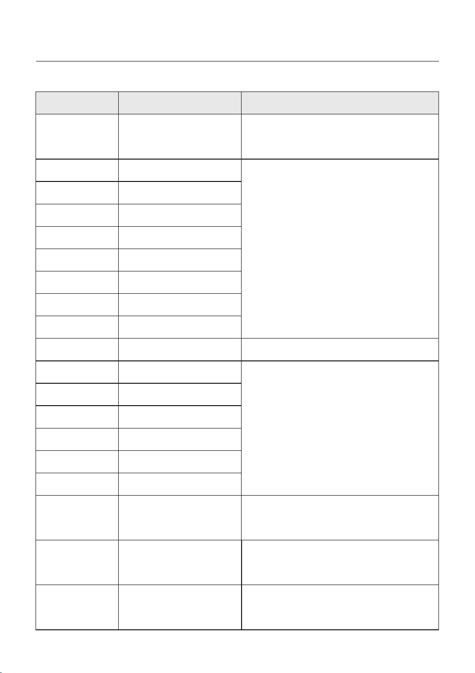
User Manual
OV-G-F01
UN-G-F01
G-PHAS E
G-F-GLU
NO-Grid
OV-G-V02
OV-G-V03
IGFO L-F
OV-G-V05
OV-G-V04
UN-G-V02
OV-G-F02
UN-G-F02
NO-Battery
Grid frequency exceeds the
upper frequency range
Grid frequency exceeds the
lower frequency range
Unbalanced grid voltage
Grid voltage frequency
fluctuation
Grid transient overvoltage
Grid transient overvoltage
Grid current tracking failure
Grid voltage RMS instanta-
neous overvoltage fault
Grid voltage exceeds the
upper voltage range
Grid voltage exceeds the
lower voltage range
Grid frequency exceeds the
upper frequency range
Grid frequency exceeds the
lower frequency range
Battery is not connected
UN-G-V01
Grid voltage exceeds the
lower voltage range
OV-G-V01
Grid voltage exceeds the
upper voltage range
Surge Alarm On-site grid surge
1. Grid side fault, restart the device.
If it is still not eliminated, please contact the
manufacturer's customer service.
1. Confirm whether the power grid is abnormal.
2. Confirm that the AC cable is properly
connected.
3. Restart the system and check if the fault
persists.
1. Restart the system, confirm if that the fault
continues.
1. Check on information page 1 – Verify the
battery voltage is within standards.
2. Measure battery voltage at plug.
No grid
1. Confirm whether the power grid is abnormal.
2. Confirm that the AC cable is properly
connected.
3. Restart the system and check if the fault
persists.
Message Name
Information Description
Troubleshooting Suggestion
OV-Vbackup
Over-Load
Inverting overvoltage
Load overload fault
1. Check whether the backup port wiring is
normal
2. Restart the system, confirm that the fault
continues.
1. Backup load power is too large, or some
inductive load startup power is too large,
need to remove some backup load, or remove
the inductive load on the backup.
7. Troubleshooting
74

User Manual
Message Name
Information Description
Troubleshooting Suggestion
BatName-FAIL
OV-Vbatt
UN-Vbatt
Fan Alarm
OV-DC01
(1020 DATA:0001)
OV-DC02
(1020 DATA:0002)
OV-BU S
(1021 DATA:0000)
UN-BUS01
(1023 DATA:0001)
UNB-BU S
(1022 DATA:0000)
UN-BUS02
(1023 DATA:0002)
DC-INT F.
(1027 DATA:0000)
OV-G-I
(1018 DATA:0000)
OV-DC A-I
(1025 DATA:0000)
OV-DC B-I
(1026 DATA:0000)
GRID-I N TF.
(1030 DATA:0000)
Wrong battery brand selection
Battery undervoltage detected
Fan alarm
DC 1 input overvoltage
DC 2 input overvoltage
DC bus overvoltage
DC bus undervoltage
DC bus unbalanced voltage
Abnormal detection of
DC bus voltage
DC hardware overcurrent
(1, 2, 3, 4)
A phase RMS value
overcurrent
DC 1 average overcurrent
DC 2 average overcurrent
AC hardware overcurrent
(abc phase)
Battery overvoltage detected
1. Confirm whether the battery model selection
is consistent with the actual one.
1. Restart the system and check if the fault
persists. If it is still not eliminated, please
contact the manufacturer's customer service.
1. Check if the internal fan is working correctly
or jammed.
1. Check if the PV voltage is abnormal
2. Restart the system, confirm that the fault
continues
1. Restart the system, confirm that the fault
continues.
1. Check if the DC wires are connected correctly
without loose connection.
1. Confirm that the grid is abnormal.
2. Confirm that the AC cable connection is not
abnormal.
3. Restart the system, confirm that the fault
continues.
1. Restart the system, confirm that the fault
continues.
1. Verify battery voltage is within standards.
Measure battery voltage at inverter connection
point. Contact your battery manufacturer for
further service.
CAN Fail CAN Fail
1. Can failure is a failure of communication
between inverter and battery. Check cable
conditions. Check to ensure you have it
plugged in on the CAN port of the battery and
inverter. Check that you are using the right
cable. Some batteries require a special
battery from the battery manufacturer.
7. Troubleshooting
75

User Manual
Message Name
Information Description
Troubleshooting Suggestion
1. Confirm that the grid is abnormal.
2. Confirm that the AC cable connection is not
abnormal.
3. Restart the system, confirm that the fault
continues.
DCInj-FAU LT
(1037 DATA:0000)
The current DC component
exceeds the limit
IGBT-OV-I
(1048 DATA:0000)
OV-TE M
(1032 DATA:0000)
UN-TEM
(103A DATA:0000)
PV I SO-PRO01
(1033 DATA:0001)
PV I SO-PRO02
(1033 DATA:0002)
12Power-FAU LT
(1038 DATA:0000)
ILeak-PRO01
(1034 DATA:0001)
ILeak-PRO02
(1034 DATA:0002)
ILeak-PRO03
(1034 DATA:0003)
ILeak-PRO04
(1034 DATA:0004)
ILeak_Check
(1039 DATA:0000)
GRID-I N TF02
(1046 DATA:0000)
OV-Vbatt-H/
OV-BU S-H
(1051 DATA:0000)
IGBT overcurrent
Module over temperature
Low temperature protection
PV negative ground fault
PV positive ground fault
12V undervoltage failure
Leakage current failure 01
(30mA)
Leakage current failure 02
(60mA)
Leakage current failure 03
(150mA)
Leakage current failure 04
Leakage current sensor
failure
Power grid disturbance 02
Battery overvoltage hardware
failure / VBUS
1. Restart the system, confirm that the fault
continues.
1. Check whether the surrounding environment
of the inverter has poor heat dissipation.
2. Confirm whether the product installation
meets the requirements.
RelayChk-FAIL
(1035 DATA:0000)
Relay failure
1. Restart the system, confirm that the fault
continues.
1. Check the working environment temperature
of the inverter.
2. Restart the system to confirm if the fault
continues.
1. Check whether the PV strings have insulation
problems.
2. Check whether the PV cable is damaged.
1. Check current leakage to ground.
Verify your grounding.
Verify all wires are in good condition and not
leaking current to ground.
1. Confirm whether the grid is seriously distorted.
2. Check whether the AC cable is connected
reliably.
1. Check if the battery circuit breaker is tripping.
2. Check if the battery is damaged.
7. Troubleshooting
76
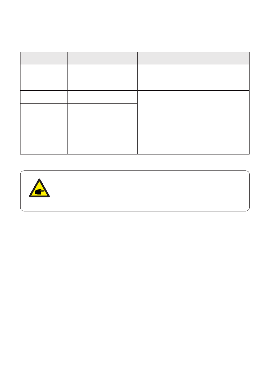
User Manual
OV-IL L C
(1052 DATA:0000)
LLC hardware overcurrent
1. Check whether the backup load is overloaded.
2. Restart the system, confirm that the fault
continues.
DSP-B-FAULT
(1036 DATA:0000)
AFCI-Check
(1040 DATA:0000)
ARC- FAULT
(1041 DATA:0000)
The master-slave DSP
communication is abnormal
AFCI self-test failure
AFCI failure
INI-FAULT
(1031 DATA:0000)
AD zero drift overlink
1. Restart the system, confirm that the fault
continues.
1. Verify connections are tight within your PV
system. Arc fault settings can be changed in
advanced settings if further adjustment is
necessary.
Table 7.1 Fault message and description
Message Name
Information Description
Troubleshooting Suggestion
NOTE:
If the inverter displays any alarm message as listed in Table 7.1; please
turn off the inverter and wait for 5 minutes before restarting it .
If the failure persists, please contact your local distributor or the service
center.
7. Troubleshooting
77
1. Serial number of Solis Singles Phase Inverter;
2. The distributor/dealer of Solis Singles Phase Inverter (if available);
3. Installation date.
4. The description of the problem together with necessary information, pictures,
attachment.
5. The PV array configuration (e.g. number of panels, capacity of panels, number of
strings, etc.);
6. Your contact details.
Please keep ready with you the following information before contacting us.

8. Specifications
User Manual
Max. input voltage
Start-up voltage
MPPT voltage range
MPPT number/Max input strings number
Max. input current
Max. usable PV input power
Recommended max. PV array size
Technical Data
S6-EH3P60K10-LV-YD-H
120kW
180V
150-950V
10/20
10*42A
1000V
S6-EH3P75K10-LV-YD-H
Input DC (PV side)
Rated voltage
600V
Max. short circuit current 10*60A
150kW
78
120kW 150kW
Battery Voltage range
Max. charge / discharge current
Number of battery port
Maximum charge / discharge current of each port
Communication
100A*2
2
100A
CAN/RS485
300 - 950V
Battery Type
Li-ion
Battery
Rated output power
Max. apparent output power
Back-up switch time
Rated output voltage
Rated frequency
THDv(@linear load)
60kW
1.6 times of rated power, 10s
2 times of rated power, 200ms
Output AC(Back-up)
<10ms
75kW
50 Hz/60 Hz
<3%
3/(N)/PE, 127V / 220V
3/(N)/PE, 133V / 230V
Input AC (Grid side)
Max. input current
250A
1.4 times of rated power, 10s
1.6 times of rated power, 200ms
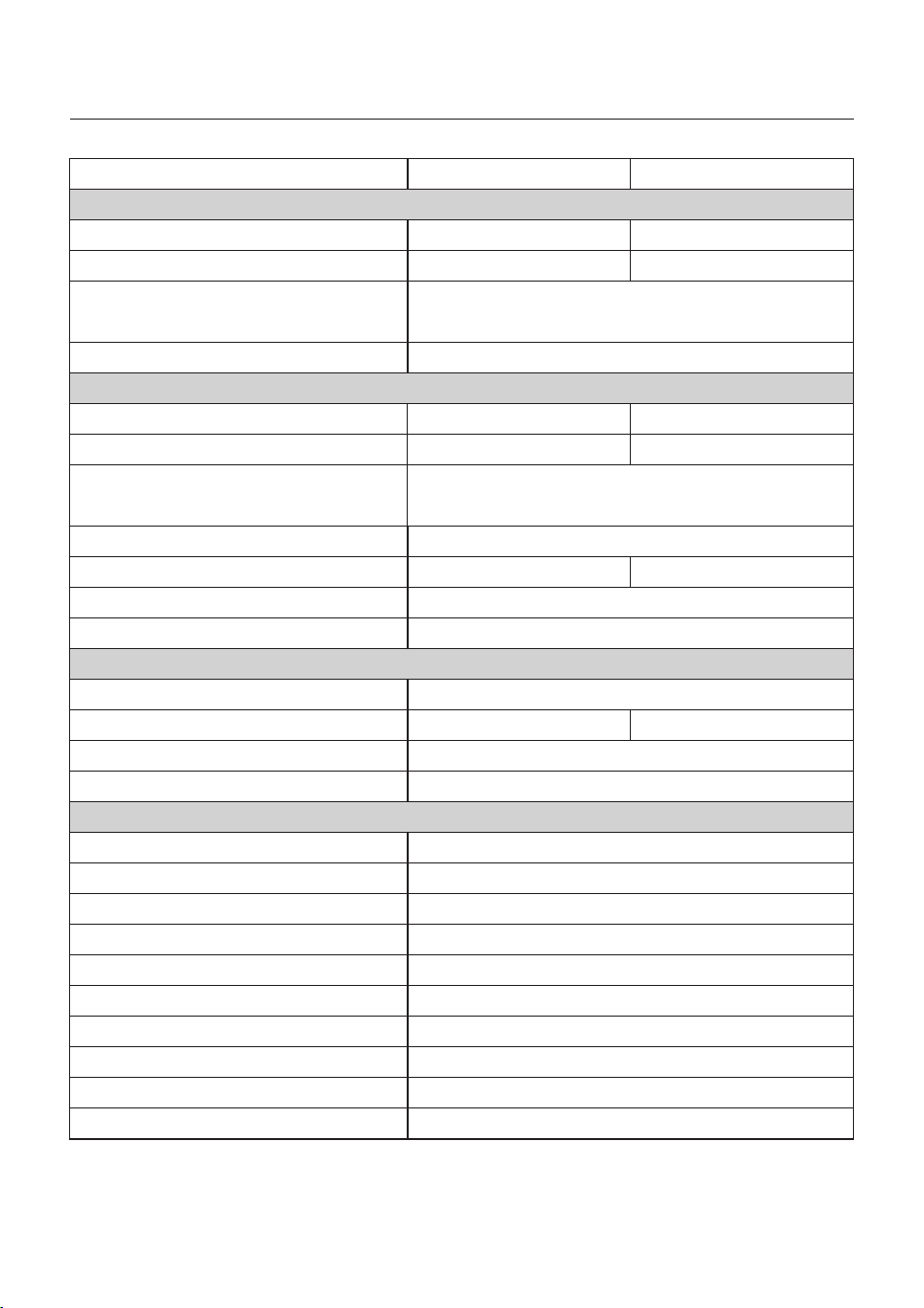
Max. efficiency
EU efficiency
Battery charged efficiency
Battery discharged efficiency
94.5%
95.6%
95.6%
Efficiency
96.0%
Technical Data
8. Specifications
User Manual
79
Rated output power
Max. apparent output power
Output AC(Grid side)
Power Factor
>0.99 (0.8 leading - 0.8 lagging)
THDi
<3%
Rated grid output current
Rated grid frequency
50Hz/60Hz
Rated grid voltage
Protection
Anti-islanding protection
Insulation Resistor detection
Output over current protection
Output short protection
Output over voltage protection
DC switch
DC reverse polarity protection
Protection class / Over voltage category
Surge protection
Optional
Yes
Yes
Yes
Yes
Yes
Yes
DC(PV ll, battery ll), AC(llI)
Yes
Integrated AFCI 2.0
S6-EH3P60K10-LV-YD-H S6-EH3P75K10-LV-YD-H
Input AC (Generator)
Max. input power
Rated input current
Rated input frequency
Rated input voltage
50Hz/60Hz
60kW
75kW
157.5A/150.6A
196.8A/188.2A
60kW
75kW
60kVA
75kVA
157.5A/150.6A
DC Type II/AC Type II
196.8A/188.2A
94.6%
3/(N)/PE, 127V / 220V
3/(N)/PE, 133V / 230V
3/(N)/PE, 127V / 220V
3/(N)/PE, 133V / 230V

Features
Terminal connector
Battery connnection
Display
Communication
Warranty
7.0" L C D display & Bluetooth + APP
CA N, RS485-115200, Ethernet, optional:Wi-Fi, cellular, LAN
5 years (Extendable to 20 years)
AC connection
Terminal Block
Grid connection standard
G99, VDE-AR-N 4105 / VDE V 0124, EN 50549-1&2/
EN 50549-10, VDE 0126 / UTE C 15/VFR:2019,
NTS 631/RD 1699/RD 244 / UNE 206006 / UNE 206007-1,
CEI 0-21, C10/11, NRS 097-2-1, TOR, EIFS 2018.2,
IEC 62116, IEC 61727, IEC 60068, IEC 61683, EN 50530,
MEA, PEA,PORTARIA Nº 140, DE 21 DE MARÇO DE 2022
Safty/EMC standard
IEC/EN 62109-1/-2, IE C/EN 61000-6-2/-4, EN 55011
3000m
Max.operation altitude
MC4 Quick connection plug
PV connnection
Dimensions(W/H/D)
Max. power per phase (grid & back-up)
Max. allowable phase imbalance (grid & back-up)
1185*862*435mm
100%
-25℃~+60℃
Weight
Operation temperature range
General data
170kg
Transformerless
Topology
IP66
<70 dB(A)
Intelligent redundant fan-cooling
Relative humidity
Ingress protection
Noise emission (typical)
Cooling concept
Technical Data
8. Specifications
User Manual
0-100%
80
S6-EH3P60K10-LV-YD-H S6-EH3P75K10-LV-YD-H
20kW
25kW
8. Specifications
User Manual
81
Max. input voltage
Start-up voltage
MPPT voltage range
MPPT number/Max input strings number
Max. input current
Battery Voltage range
Max. usable PV input power
Recommended max. PV array size
Max. charge / discharge current
Number of battery port
Maximum charge / discharge current of each port
Communication
Technical Data
S6-EH3P80K10-NV-YD-H
160kW
180V
150-950V
10/20
10*42A
2
100A
CAN/RS485
1000V
300 - 950V
Battery Type
Li-ion
S6-EH3P99.9K10-NV-YD-H
Input DC (PV side)
Rated voltage
600V
Max. short circuit current 10*60A
Battery
200kW
160kW 200kW
Rated output power
Back-up switch time
Rated output voltage
Rated frequency
THDv(@linear load)
80kW
Output AC(Back-up)
<10ms
99.9kW
<3%
3/N/PE, 220V/380 V
3/N/PE, 230V/400 V
Input AC (Grid side)
Max. input current
250A
50 Hz/60 Hz
Max. apparent output power
1.6 times of rated power, 10s
2 times of rated power, 200ms
100A*2

8. Specifications
User Manual
82
Max. efficiency
EU efficiency
Battery charged efficiency
Battery discharged efficiency
97.0%
97.0%
Efficiency
97.5%
Technical Data
Rated output power
Max. apparent output power
Output AC(Grid side)
Power Factor
>0.99 (0.8 leading - 0.8 lagging)
THDi
<3%
Rated grid output current
Rated grid frequency
50Hz/60Hz
Rated grid voltage
Protection
Anti-islanding protection
Insulation Resistor detection
Output over current protection
Output short protection
Output over voltage protection
DC switch
DC reverse polarity protection
Yes
Yes
Yes
Yes
Yes
Yes
Yes
Input AC (Generator)
Max. input power
Rated input current
Rated input frequency
Rated input voltage
80kW
99.9kW
121.6A/115.5A
151.8A/144.2A
80kW
99.9kW
80kVA
99.9kVA
3/N/PE, 220V/380 V
3/N/PE, 230V/400 V
3/N/PE, 220V/380 V
3/N/PE, 230V/400 V
S6-EH3P80K10-NV-YD-H S6-EH3P99.9K10-NV-YD-H
50Hz/60Hz
121.6A/115.5A 151.8A/144.2A
Protection class / Over voltage category
Surge protection
Optional
DC(PV ll, battery ll), AC(llI)
Integrated AFCI 2.0
DC Type II/AC Type II
96.9% 97.1%

8. Specifications
User Manual
83
Features
Terminal connector
Battery connnection
Display
Communication
Warranty
7.0" L C D display & Bluetooth + APP
CA N, RS485-115200, Ethernet, optional:Wi-Fi, cellular, LAN
5 years (Extendable to 20 years)
AC connection
Terminal Block
Grid connection standard
G99, VDE-AR-N 4105 / VDE V 0124, EN 50549-1&2/
EN 50549-10, VDE 0126 / UTE C 15/VFR:2019,
NTS 631/RD 1699/RD 244 / UNE 206006 / UNE 206007-1,
CEI 0-21, C10/11, NRS 097-2-1, TOR, EIFS 2018.2,
IEC 62116, IEC 61727, IEC 60068, IEC 61683, EN 50530,
MEA, PEA,PORTARIA Nº 140, DE 21 DE MARÇO DE 2022
Safty/EMC standard
IEC/EN 62109-1/-2, IE C/EN 61000-6-2/-4, EN 55011
3000m
Max.operation altitude
MC4 Quick connection plug
PV connnection
Dimensions(W/H/D)
Max. power per phase (grid & back-up)
Max. allowable phase imbalance (grid & back-up)
100%
-25℃~+60℃
Weight
Operation temperature range
General data
170kg
Transformerless
Topology
IP66
Intelligent redundant fan-cooling
Relative humidity
Ingress protection
Cooling concept
Technical Data
0-100%
26.66kW
33.3kW
S6-EH3P80K10-NV-YD-H S6-EH3P99.9K10-NV-YD-H
<70 dB(A)
Noise emission (typical)
1185*862*435mm
8. Specifications
User Manual
84
Max. input voltage
Start-up voltage
MPPT voltage range
MPPT number/Max input strings number
Max. input current
Battery Voltage range
Max. usable PV input power
Recommended max. PV array size
Max. charge / discharge current
Number of battery port
Maximum charge / discharge current of each port
Communication
Technical Data
S6-EH3P100K10-NV-YD-H
200kW
180V
150-950V
10/20
10*42A
2
100A
CAN/RS485
1000V
300 - 950V
Battery Type
Li-ion
S6-EH3P125K10-NV-YD-H
Input DC (PV side)
Rated voltage
600V
Max. short circuit current 10*60A
Battery
250kW
200kW 250kW
Rated output power
Back-up switch time
Rated output voltage
Rated frequency
THDv(@linear load)
100kW
Output AC(Back-up)
<10ms
125kW
<3%
3/N/PE, 220V/380 V
3/N/PE, 230V/400 V
Input AC (Grid side)
Max. input current
250A
50 Hz/60 Hz
Max. apparent output power
1.6 times of rated power, 10s
2 times of rated power, 200ms
1.4 times of rated power, 10s
1.6 times of rated power, 200ms
100A*2

8. Specifications
User Manual
85
Max. efficiency
EU efficiency
Battery charged efficiency
Battery discharged efficiency
97.0%
97.0%
Efficiency
97.5%
Technical Data
Rated output power
Max. apparent output power
Output AC(Grid side)
Power Factor
>0.99 (0.8 leading - 0.8 lagging)
THDi
<3%
Rated grid output current
Rated grid frequency
50Hz/60Hz
Rated grid voltage
Protection
Anti-islanding protection
Insulation Resistor detection
Output over current protection
Output short protection
Output over voltage protection
DC switch
DC reverse polarity protection
Yes
Yes
Yes
Yes
Yes
Yes
Yes
Input AC (Generator)
Max. input power
Rated input current
Rated input frequency
Rated input voltage
100kW
125kW
151.9A/144.3A
189.9A/180.4A
100kW
125kW
100kVA
125kVA
3/N/PE, 220V/380 V
3/N/PE, 230V/400 V
3/N/PE, 220V/380 V
3/N/PE, 230V/400 V
50Hz/60Hz
S6-EH3P100K10-NV-YD-H S6-EH3P125K10-NV-YD-H
151.9A/144.3A 189.9A/180.4A
Protection class / Over voltage category
Surge protection
Optional
DC(PV ll, battery ll), AC(llI)
Integrated AFCI 2.0
DC Type II/AC Type II
97.1% 97.2%

8. Specifications
User Manual
86
Features
Terminal connector
Battery connnection
Display
Communication
Warranty
7.0" L C D display & Bluetooth + APP
CA N, RS485-115200, Ethernet, optional:Wi-Fi, cellular, LAN
5 years (Extendable to 20 years)
AC connection
Terminal Block
Grid connection standard
G99, VDE-AR-N 4105 / VDE V 0124, EN 50549-1&2/
EN 50549-10, VDE 0126 / UTE C 15/VFR:2019,
NTS 631/RD 1699/RD 244 / UNE 206006 / UNE 206007-1,
CEI 0-21, C10/11, NRS 097-2-1, TOR, EIFS 2018.2,
IEC 62116, IEC 61727, IEC 60068, IEC 61683, EN 50530,
MEA, PEA,PORTARIA Nº 140, DE 21 DE MARÇO DE 2022
Safty/EMC standard
IEC/EN 62109-1/-2, IE C/EN 61000-6-2/-4, EN 55011
3000m
Max.operation altitude
MC4 Quick connection plug
PV connnection
Dimensions(W/H/D)
Max. power per phase (grid & back-up)
Max. allowable phase imbalance (grid & back-up)
100%
-25℃~+60℃
Weight
Operation temperature range
General data
170kg
Transformerless
Topology
IP66
Intelligent redundant fan-cooling
Relative humidity
Ingress protection
Cooling concept
Technical Data
0-100%
33.33kW
41.66kW
S6-EH3P100K10-NV-YD-H S6-EH3P125K10-NV-YD-H
<70 dB(A)
Noise emission (typical)
1185*862*435mm
8. Specifications
User Manual
87
Max. input voltage
Start-up voltage
MPPT voltage range
MPPT number/Max input strings number
Max. input current
Max. usable PV input power
Recommended max. PV array size
Technical Data
S6-EH3P75K10-NV-YD-H
180V
150-950V
10/20
10*42A
1000V
Input DC (PV side)
Rated voltage
600V
Max. short circuit current 10*60A
150kW
150kW
Battery Voltage range
Max. charge / discharge current
Number of battery port
Maximum charge / discharge current of each port
Communication
2
100A
CAN/RS485
300 - 950V
Battery Type
Li-ion
Battery
Rated output power
Max. apparent output power
Back-up switch time
Rated output voltage
Rated frequency
THDv(@linear load)
1.6 times of rated power, 10s
2 times of rated power, 200ms
Output AC(Back-up)
<10ms
75kW
<3%
3/N/PE, 220V/380 V
Input AC (Grid side)
Max. input current
250A
60 Hz
100A*2
8. Specifications
User Manual
88
Max. efficiency
EU efficiency
Battery charged efficiency
Battery discharged efficiency
96.9%
97.0%
97.0%
Efficiency
97.5%
Technical Data
Rated output power
Max. apparent output power
Output AC(Grid side)
Power Factor
>0.99 (0.8 leading - 0.8 lagging)
THDi
<3%
Rated grid output current
Rated grid frequency
60Hz
Rated grid voltage
Protection
Anti-islanding protection
Insulation Resistor detection
Output over current protection
Output short protection
Output over voltage protection
DC switch
DC reverse polarity protection
Yes
Yes
Yes
Yes
Yes
Yes
Yes
Input AC (Generator)
Max. input power
Rated input current
Rated input frequency
Rated input voltage
75kW
114.0A
3/N/PE, 220V/380 V
60Hz
S6-EH3P75K10-NV-YD-H
75kW
75kVA
114.0A
Protection class / Over voltage category
Surge protection
Optional
DC(PV ll, battery ll), AC(llI)
Integrated AFCI 2.0
DC Type II/AC Type II
3/N/PE, 220V/380 V
8. Specifications
User Manual
89
Features
Terminal connector
Battery connnection
Display
Communication
Warranty
7.0" L C D display & Bluetooth + APP
CA N, RS485-115200, Ethernet, optional:Wi-Fi, cellular, LAN
5 years (Extendable to 20 years)
AC connection
Terminal Block
Grid connection standard
ORDINANCE (PORTARIA) NO.140
ORDINANCE NO. 515
Safty/EMC standard
IEC/EN 62109-1/-2, IE C/EN 61000-6-2/-4, EN 55011
3000m
Max.operation altitude
MC4 Quick connection plug
PV connnection
Dimensions(W/H/D)
Max. power per phase (grid & back-up)
Max. allowable phase imbalance (grid & back-up)
100%
-25℃~+60℃
Weight
Operation temperature range
General data
170kg
Transformerless
Topology
IP66
Intelligent redundant fan-cooling
Relative humidity
Ingress protection
Cooling concept
Technical Data
0-100%
25kW
S6-EH3P75K10-NV-YD-H
<70 dB(A)
Noise emission (typical)
1185*862*435mm

9. Appendix - FAQs
User Manual
Frequently Asked Questions
Q2: Why I have "BATName-Fail" Alarm on the inverter ?
A: Please check in the "Battery Setting->Battery Model" setting and confirm you selected the
correct battery option as the nameplate of your battery module.
Q3:Why I have "MET-SLT-Fail" Alarm on the inverter?
A: Please check in the "Meter Setting->Meter Type" setting and confirm you selected the
correct meter option corresponding to your smart meter.
Q4:Why the power values on the screen are fluctuating
very fast?
A: If your loads are changing drastically, the inverter will adjust its power accordingly. If you
confirm the loads are stable while the inverter power is changing very fast, please double
check your meter CT's direction and make sure the arrow is towards grid.
Q1: Why I have "CAN Fail" Alarm on the inverter?
A:"CAN Fail" indicates the CAN communication between inverter and battery is lost.
Please double check if your CAN cable is correctly connected and if your battery is power on.
Q5: Why I have "OV-ILLC" Alarm on the inverter ?
A: OV-ILLC indicates there is an overcurrent issue on the internal LLC circuit. It could be
transient status during extreme condition such as overload. If it happens constantly or too
frequent and the extreme conditions have been excluded, please contact Solis service team.
Q6: Why I have "OV-BATT-H" Alarm on the inverter ?
A: OV-BATT-H indicates over voltage issue on the hardware of battery circuit. It could be
caused by high battery voltage at full SOC, battery suddenly switching off, etc. If it happens
constantly or too frequent and the extreme conditions have been excluded, please contact
Solis service team.
Q7: Why I have "No-Battery" Alarm on the inverter?
A: Please double check if the battery power cables have been correctly connected and the
battery breaker (on battery or external) has been turn on. If you don't want to connect the
battery for now, please select the "No battery" option in "Battery Setting->Battery Model"
to prevent the alarm to show up.
90

If you encounter any problem on the inverter, please find out the inverter S/N
and contact us, we will try to respond to your question ASAP.
Please adhere to the actual products in case of any discrepancies in this user manual.
Ginlong Technologies Co., Ltd.
No. 57 Jintong Road, Binhai Industrial Park, Xiangshan, Ningbo,
Zhejiang, 315712, P.R.China.
Tel: +86 (0)574 6578 1806
Web: www.solisinverters.com