MoticScope 1
Biological Microscope
Instruction Manual
WWW.MOTIC.COM
MOTIC CHINA GROUP CO., LTD.
If the equipment is used in a manner
not specified by the manufacturer,
the protection provided by the
equipment may be impaired.
Note
Complete reading of this manual
before opeartion is required.

1
Contents
1. Safety Instructi ons 3
1.1 Safety Tips 3
1.2 Safety Considerations 3
1.3 Transportation, Unpacking, and Storage 4
1.4 Operating Precautions 4
1.5 Working Environm ent 5
1.6 Quality Assurance 5
2. Product Overvi ew 7
2.1 Intended Use 7
2.2 Structural Composition 7
3. Product Operation 8
3.1 Check the Input Voltage 8
3.2 Installation Method 9
3.2.1 Eyepieces 9
3.2.2 Observation Tube (Complete Digital Head) 9
3.2.3 Objective Lenses 9
3.3 Routine Microscopic Operat
ion 10
3.3.1 Power Switch 10
3.3.2 Handling and Placement of the Microscope 10
3.3.3 Brightness Adjustment 10
3.3.4 Stage Adjustment 11
3.3.5 Objective Lens Switching 11
3.3.6 Focusing 12
3.3.7 Condenser Adjustment 13
3.3.8 Oil-Immersi on Objective Lens 13
3.3.9 Extended Interface Functions 14
3.4 Digital Microscopy Operation 15
3.4.1 Using the Software 15
3.4.2 Reset 16
3.4.3 Calibration 16
4. Maintenance and Care 17

2
4.1 Cleaning 17
4.1.1 Optical Lens Surfaces 17
4.1.2 Surfaces of Painted Parts and Plastic Parts 18
4.2 Storage 18
4.3 Lamp Replacement 18
4.3.1 LED Lamp 18
4.4 Maintenan ce Inspec t i on 19
Appendix 1 Troubleshooting T able 20
Appendix 2 Technical Specifications Tabl e 23
Appendix 3 Product Configuration Table 24
3
1. Safety Instructions
1.1 Safety Tips
Before using this pr oduct, please read the instruction manual carefu l l y to ensure safe operation and
optimal performance, an d follow all precautions a nd warn i ngs provided in the manual. Please fami l i arize
yourself with the meanings of the following sa f ety symbols:
Symbol Description
Caution: Hazard. Indicates that the instrument may cause personal injury or equip ment
damage.
Caution: Hot Surface Hazard. Indicates that the surface of the instrument may pre sent a
risk of burns due to high temperature.
Information and Tips. Ind i cates useful information and guidance.
Recycling. Indicates that disposal of instrume nt waste must be carried out in strict
compliance with applicable requirements.
Caution: Electric Shock Hazard. Indicates the presence of potentially hazardous
voltage/cur rent in the instrument.
1.2 Safety Conside rations
This product is designed, manufactur ed, and inspected in accordance with the safety standards
GB/T 42125.1-2024 and YY 0648-20 08.
This product complies with the emission an d immunity requiremen t s spec i f i ed in IEC 61326, GB/T
18268.1, and GB/T 18268.26 series standard s.
Before using th i s pr oduct, ass ess the elec t romagnetic enviro nment. Do not use it near strong
sources of e l ectromagne t i c radiation, such as unshiel ded radio -frequency sources, as this may
interfere with the normal operation of th e equi pment.
This product is designed and tested as Class B equipment in accordance with GB 4824. In a
domestic environment, the Product may cause radio interference and requires protection.
Please use only the power cord specified by the manufacturer; otherwise, the safety performance of
this product may be comprom i sed.
Connect the power cable properly, and ensure that the Product's groun ding termi nal is properl y
connected to the gro unding terminal of the wall socket. Otherwise, the des i gned electrical safety
performan ce of this p roduct may be compro mised.
Any el ectronic equipme nt connected t o this product must comply with the requirements of EN/IEC
62368 and other applicable local safety rules and standards.
The characteristics of the biological microsc ope specified in the registered product standard are:
Overvoltag e Category II; Pollution Degree 2.
4
1.3 Transport ation, Unpacking, and Stora ge
In accordance with standard commercial practice, this produ ct is transpo rted in cor rugated cartons
with foam packaging. Please reuse the o riginal packaging for any transportation.
During transportation and storage, protective measure s such as shielding from direct sunlight,
keeping d ry from rain, and preventing impact damage must be taken.
When unp acking, please check all accessories agains t the packi ng list to confirm that e verything is
complete.
For long-term storage or retu rn to the factory, please use the original packaging to avoid voiding the
warranty.
1.4 Operating Pre cautions
This product is a precision inst rument. Improper handling or operation may impair its
performan ce or cause damage to the in strument. To ensure st able a nd reliable operation, place
the in strument on a firm, secure table or on a wor kbench equipped with vi bration isolation.
When using this product, be sur e to observe the following p recautions at all times.
This product ma y onl y be operated by trained personnel. The operat or shall un derstand the hazar ds
associated with biological mi croscope e xamination and its var i ous related application fields.
This product is not equipp ed with any special protective devices fo r corrosive, potentially infectious,
toxic, rad i oactive, or other health-hazardous samples. When handling such tests, all legal
requireme nts mu st be observed, especially thos e relating to accident preve ntion.
Do not use this product in locations where the disconnect devic e (switch and power outlet) is difficult
to oper ate.
If it has been determined that t he pro t ective function has f ailed, stop using the prod uct immediately
and contact the Motic after-sales technical service depart ment for repair.
Please ensure that this product is place d on a non-metalli c work surfac e so as not to affect its
functional perfor mance.
Before using immersio n oil, be sure to read the following safety precautio ns carefully.
Immersion oil may ir ritate the skin. Avo i d contact with skin, eyes, and c l othing.
After skin con t act, w ash thoroughly with plenty of water and soap until the immersion oil has been
completely removed from the skin.
After e ye contac t , imm ediately flush the eye s with plenty of water for at least 5 minutes. If irritation
persists,

5
consult a physic i an.
Dispose of immersion oil properly as was t e, and do not allow it to enter surface water or drains.
For disposal, be sure t o comply with local government laws and regulations.
1.5 Working Env i ronment
Do not use the Pr oduct i n a place with direc t sunlight, high temperature and humidity, dus t or vibration.
For indoor u se:
At an altitude of no more than 2,000 meter s above se a level (for use above this altitude, cor rection
factors shall be applied in accordance w i t h national st andards);
Ambient temperature from +5 °C to +40 °C, with humidity from 30% t o 7 5% (non-conde nsing);
Power supply voltage fluctuation within ±10% of the rated voltage, and atmospheric pressure from
75 kPa to 106 kPa;
During transportation and storage:
Storage a mbient temperat ure from - 20 °C to +4 0 °C, with humid i t y from 10% t o 9 0%
(non-cond ensing).
During transportation (in packaging), the permissible ambient temperature is from -40 °C to +55 °C,
with humidity from 10% to 90% (non-condensing); protective measures such as shielding fr om direct
sunlight, preventin g rain exposu re, a nd avoid i ng breakage must be taken. If you need to package
this instrument for long-distance transportation, please contact the manufactur er (see the back
cover) o r your local distribut or.
1.6 Quality Assurance
This product and its o
riginal access ories may only be used for the inspection operations described in this
manual. Please note the following warranty information for this product:
The m anufacturer provides a warran t y against mate rial defects and product quali t y defects ex i sting
at the time of shipment.
When unp acking, please check the completen ess of the configuration a gainst the packing list; if any
defect is foun d, report it to t he manufacturer immed i ately, and upon receipt of the report, the
manufacturer shall prom ptly re pair or replace the defective item.
The m anufacturer assumes no liability for equipmen t damage caused by imp roper operation or any
use other tha n the intended use.
The m anufacturer does not provide warrant y coverage for product failures or defects resulting from
normal wear and tear (especially wear pa rts and consumables ) or improper use. .
The m anufacturer assumes no liability for damage to the instrument ca used by opera t i onal err ors,

6
negligence, or unautho rized dis assembly, especiall y where the biological microscope has been
disassembl ed or parts have been replaced, or where accessorie s from other manufac t urers have
been used.
The m anufacturer assumes no liability for any use ot her th an the intended use, includi ng the use of
any indi vidual components. This provision al so applies to all af t er-sales service or repair work
performed by personnel who a re not authorized servic e providers. Failure to comply will result in the
immediate voiding of all warr anty ri ghts.
Precautions:
Production date: See the co mpliance certificate
Warranty period for mechanical parts: 8 years
Warranty period for electronic parts: 1 year
7
2. Product Overview
2.1 Intended Use
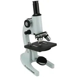
This product is an upr i ght biological microscope for teaching purposes. It is used to magnif y an d observe
specimens under visib l e light and is mainly in t ended for basic experimental teaching and routin e
laboratory tes t i ng. Digital models can be equippe d with an external or built-in camera system, enabling
functions such as ima ge ca pture, video recording, and measur ement through Motic image processing
software.
2.2 Structural Co
mposition
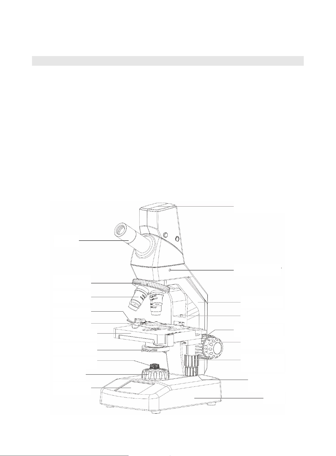
This product mainly consists of eyepieces, an observation head, an arm assembly (includin g the
objective nosep i ece and focusing mechanism), objecti ve lenses, a stage, a condenser, and a base
assembly (includ i ng the collec t or lens) .
Eyepiece
Objective
nosepiece
O
bjective lens
S
lide holder
C
ondenser
M
echanical stage
Aperture
diaphragm lever
Brightness control
knob
C
ollector lens
D
isplay screen
D
igital indicator light
Tube locking screw
Microscope arm
Focus limit screw
Coarse focus knob
Fine focus knob
Stage Y-axis
control knob
Stage X-axis
control knob
Base

8
3. Product Operation
3.1 Check the Input Voltage
The in put voltage rang e of the powe r adapter supplied with this product is AC 100-240 V, 50/60 Hz. The
auto voltage selection device applies to the voltage worldwide, but it is recommended to choose the
power cable that matches the rated vo l t age in your place . Misu se of power cable may r esult in fire
hazard or instrument damag e. To prevent electric shoc k, ensure the power switch is in th e off position
before connecting the power
cable.
Electrical specifications:
Input: DC 12 V, 2.5 A
Light source: LED 0.5 W, MAX 150 mA
Base power input
s
ocket
9
3.2 Installation Method
3.2.1 Eyepieces
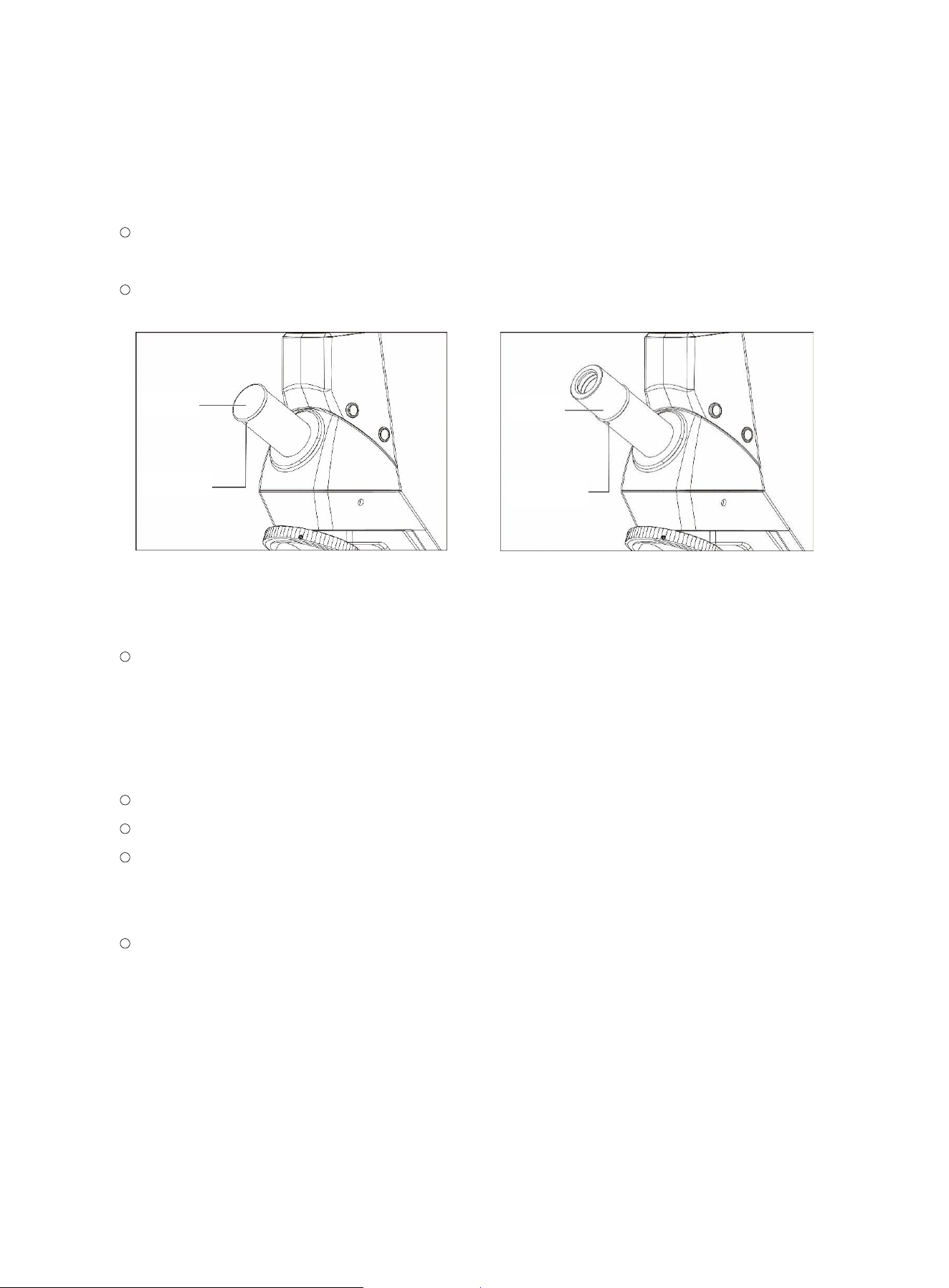
Use a T0.9 Allen wrench to loosen the eyepiece retaining screw, and remo ve the eyepiece dust
cap. (Figure 1-1)
Insert eyepieces of the s ame magnification into t he eye piece tubes, an d tighten the eye piece
retaining screw. (Figure 1-2)
(Figure 1-1) (Figure 1-2)
3.2.2 Observation Tube (Complete Digital Head)
There is a connecting ca ble between the digital observation tube and t he arm. Please oper ate
with c are. If the observation tube need s to be repl aced, please co ntact Moti c af t er-sales service
professionals to perform the operat i on.
3.2.3 Objective Lenses
Before leaving the factory, the coded objective lenses have already been installed and adju sted.
If the objecti ve lenses need to be rep l aced, first lower the stage to its l owest position.
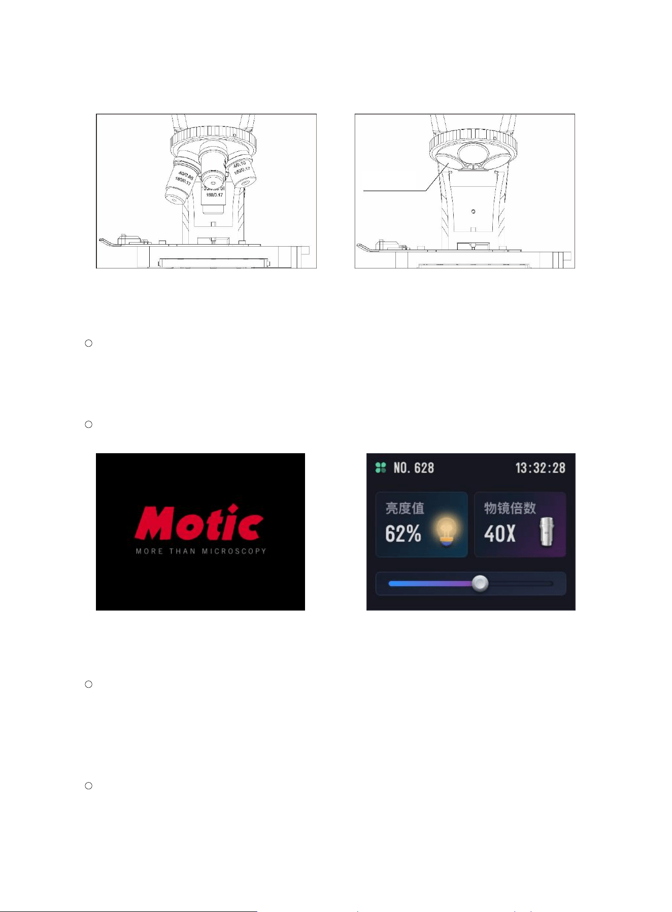
Rotate the nosepiece cl ockwise and screw in the objective lenses o ne by one in ascending order
of magnification. The correspondi ng obj ective port positions must match the objective
magnifications shown on the display screen . (Figure 2-1)
When the instrument will not be used for an extended period, remove the objective lenses for
storage and sc rew in the objective dust caps. (Figure 2-2)
D
ust cap
L
ocking scre
w
E
yepiece
L
ocking screw
10
(Figure 2-1) (Figure 2-2)
3.3 Routine Microscopic Operation
3.3.1 Power Switch
After correctly connecting the power adapte r and switching on the power supply, press the
brightness control knob for 1 second and then rele ase it to power on the unit. The display screen
will play the startup animati on, and after the s t artup animation ends, the system will en t er the
main interface. (Figure 3-1)
The m ain interface displays the current power-on duration, brig htness value, brightness
adjustment bar, and o bjective magnification. (F i gure 3-2)
(Figure 3-1) (Figure 3-2)
3.3.2 Handling and Placement of the Microscope
When carr ying the mi croscope, hold the arm with on e hand and support the base with the other,
keeping the instrument level (tilt ≤ 30°). Place it on the laboratory be nch at an appropriate
distance from the edge (approximately 7 cm), slightly to the left in front of your body.
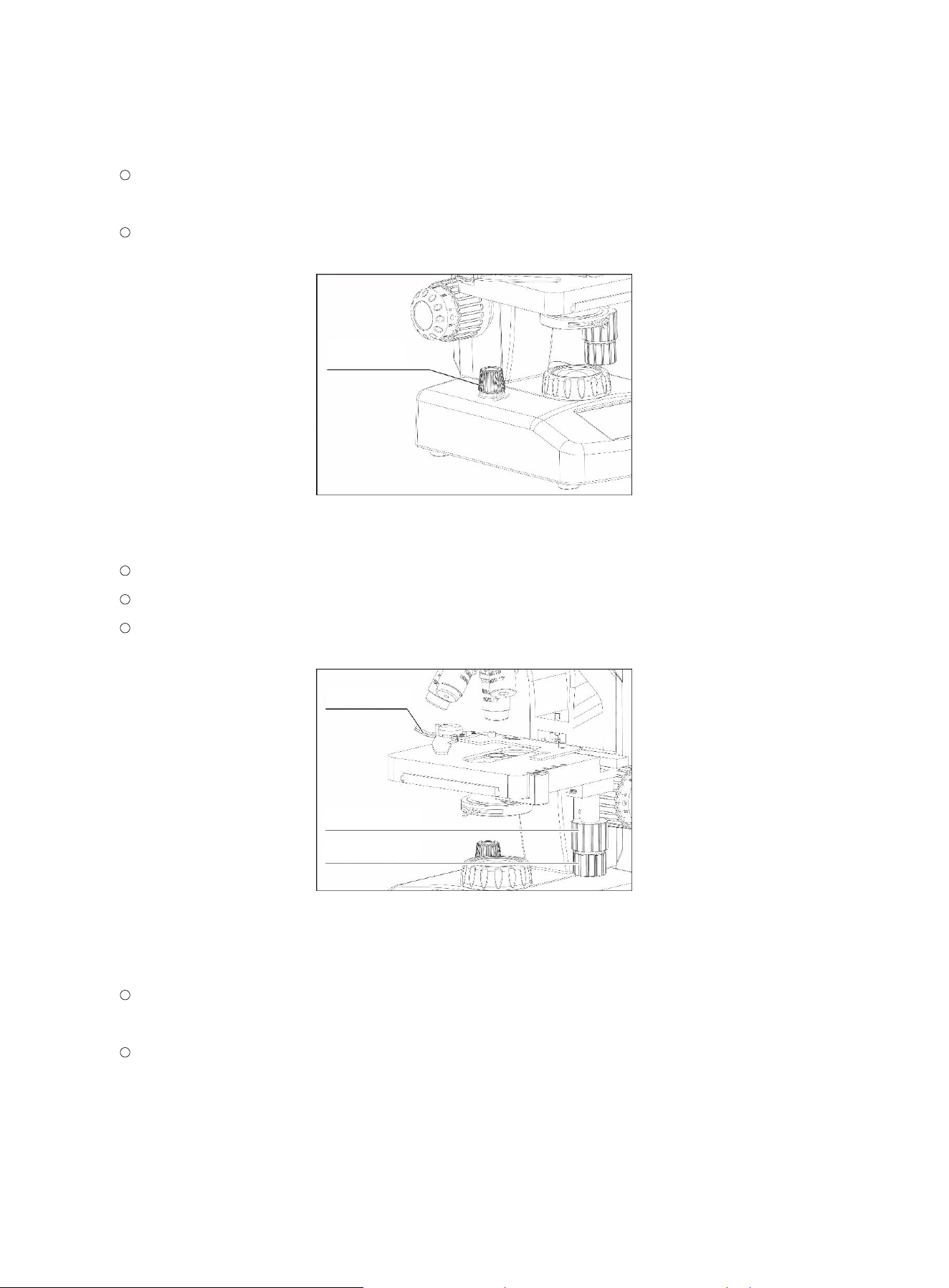
3.3.3 Brightness Adjustment
Turn the brightness control knob in the direction indicated by the printed mark in fro nt of th e kno b
to adjust to the required brightness. (Figure 4)
Objective dust
cap
11
The brightness a djustment bar at the botto m of the main inte rface also supports touch control for
brightness adjust ment.
Before visual observation, set the illuminatio n brightness t o below 20% to avoid an excessively
bright f i eld of view when observing with a low-pow er objective lens.
(Figure 4)
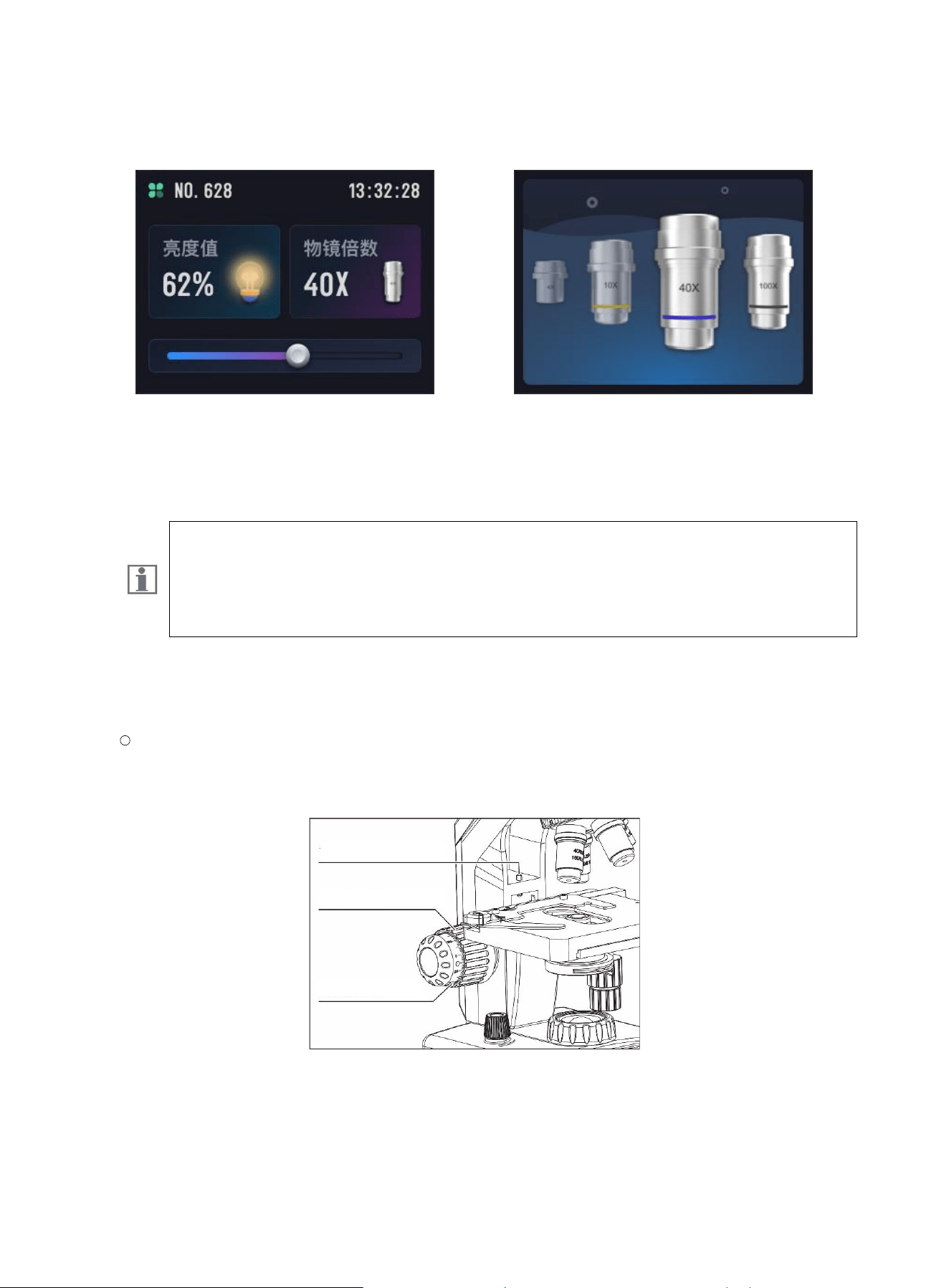
3.3.4 Stage Adjustment
Turn the coarse focus knob co unterclockwi se to lower the s t age to its lowest po sition.
Open the slide holder clip, place the specimen slide correctly on the stage, and secure it fir mly.
During observation, turn the X/Y control knobs to move th e observation area of the specimen to
the center posit i on of the condenser. (Figure 5)
(Figure 5)
3.3.5 Objective Lens Switching
When switching objective lenses, the display screen will show an animation of the currently
selected objective, and the main interfa ce will display the corr esponding objecti ve magnification.
Before observatio n, the initial objective magni f i cation is 4X. The objective lenses should be
switched clockwi se in order from low magnification to hi gh magnification.
Brightness
control knob
Slide holder clip
Y
-axis control kno
b
X
-axis control kno
b
12
(Figure 6-1) (Figure 6-2)
3.3.6 Focusing
Do not attem pt any of the following actions, other wise the focusing m echanism may
be damaged:
● Holding one focus knob tightly while turning only th e knob on the other side.
● Turning the coarse focus knob or fi ne focus knob beyond its limit position.
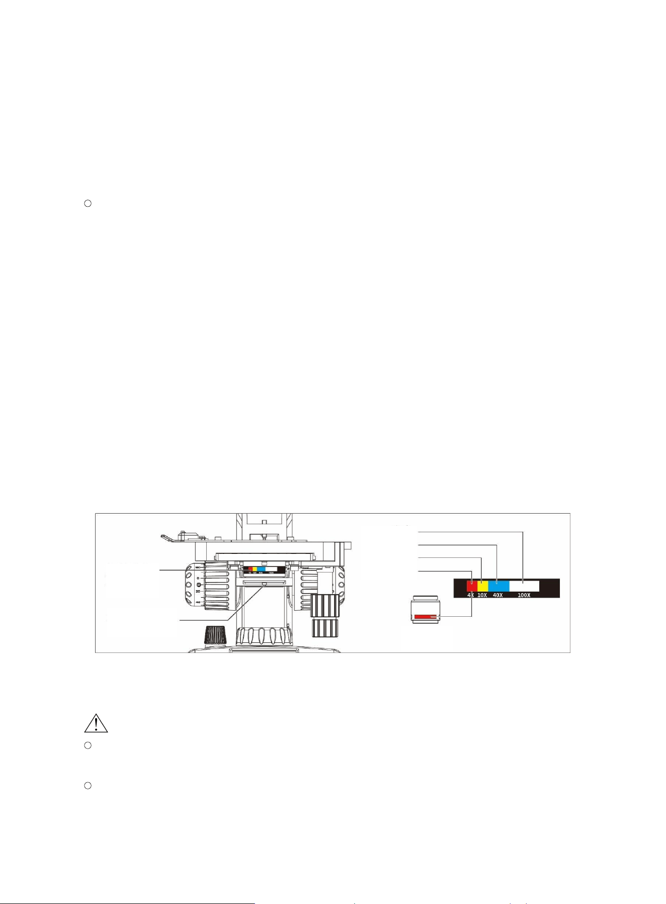
The fo cus height limit of this product has b een preset at the factory and may be adjusted if
necessary.
If the image still cannot be brought into focus whe n the focus mechanism r eaches its highest
point, th e limit screw may be loosened and adjuste d so that the sp ecimen can stil l mov e upward
by 1 mm when it is at the focal plane po sition. (F i gure 7)
(Figure 7)
Swing the low-power objective into the optical path, an d slowly turn the coarse focus knob clockwise
until t he outline of the specimen image comes into view.
Focus height limit screw
Coarse focus knob
Fine focus knob
13
Swing the high-power object i ve into the optical path, and slowly turn th e fine focus knob until the
specimen image is brought into the sharpest f ocus, t hat is, until the image pl ane is in focus.
3.3.7 Condenser Adjustment
Move the ape rture diaphragm lever to ad j ust it so that it matche s the numeri cal aperture of the
objective lens and find the position that provides the b est im age c ontrast. If the specimen
image appears too pale, slowly reduce the ape rture of the iris diaphra gm until the specimen
image becomes c l early vis i ble. If the specimen ima ge appears too dark , the diaphragm may be
opened gradually. (Fig ure 8)
Please note: the smaller the aperture of the iris diaphragm, the better the im
age contrast; th e larger
the aperture, the low er the contrast. (The purp ose of t he diaphragm is not to control the brightness of
illumination.) The best procedur e for setting the aperture is to first open it to the maxi mum and then
slowly close it until the specimen is completely in focus. Using an incorrect apertu re size may cause
the image to appear washed out. Be careful not to reduce the aperture excessivel y in order to obtain
higher contrast , as this may destroy the fine st
ructural details of the specimen in the image.
Reducing the aperture increases co ntrast and depth of field, but it al so low ers resolution and
produces diffraction. For example, the aperture setting for a 10X objective is dif f erent from that for a
40X o bjective, because the angle of li ght re quired by the object i ve is determined by its N.A. value.
After u sing the mi croscope for a short period , you will be able to find the appropriate aperture
diaphragm setting easil y.
(Figure 8)
3.3.8 Oil-Immersi on Objective Lens
When using an oil- i mmersion objec t i ve lens, note the f ollowing:
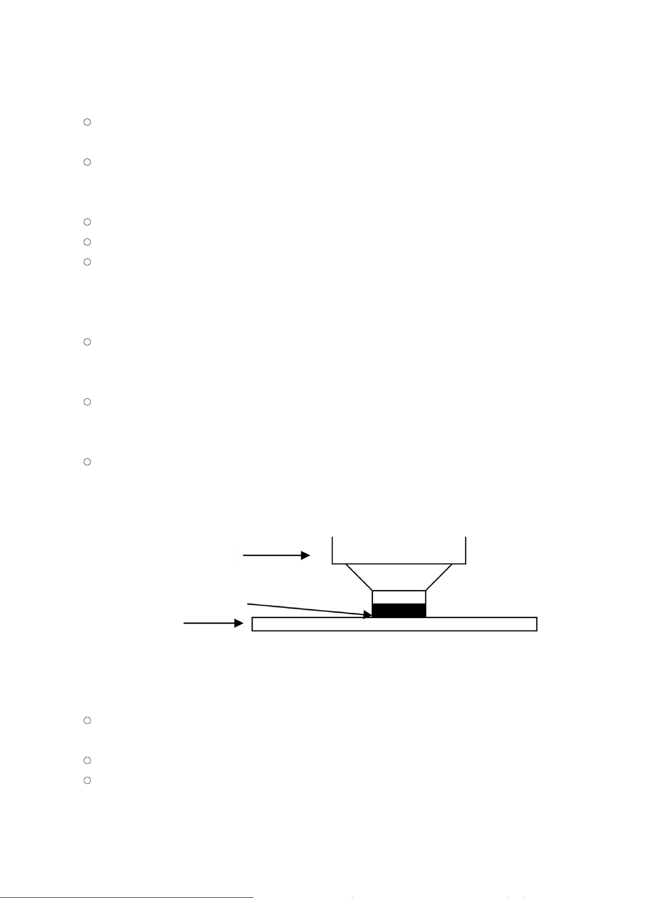
The oi l -immersion objective is marked with t he word “Oil”. During use, an appropriate amount
of ceda r oil must be appli ed b etween the cover glas s an d the front lens g roup of the objective.
The cedar oil provided by Motic is a synthet i c, non- f l uorescent, resin- f ree oil with a refractive
index of 1.515.
Color code
A
perture
d
iaphragm
A
perture
d
iaphragm lever
Whit
e
Blu
e
Yello
w
Re
d
Objective
color ring
14
Do not use a cover glass thic ker than 0.17 mm, as the spec i men will no t fall within the working
distance of the object i ve, whi ch will affect image forma t i on.
Use as little immersion oil as possible. Any oil film remaining on the immersion objective, or any
oil that spreads onto the surface of a dry objective, will have a significant negative effect on the
image.
Make sure there are no air bubbles in the im mersion oil, as bubbles may reduce image qualit y.
Please operate strictly according to the following steps:
After focusing on the spec i men with a low-power objectiv e, rotat e the oil-immersion objective
into the obser vation position, remove the specimen, place a drop of immer sion oi l on the
observation ar ea of the specimen, rep osition the specimen, and turn t he fine focus knob to focus
on the specime n. (Figu re 9)
Remove the eyepiece, and after safely opening the field diaphragm and aperture diaphragm,
observe t he objective exit pupil (the bright circular image) inside the observation tube to check
for air bubbl es.
If air bubbles are found, they may be removed by rotating the nos epiece to swing the immersed
objective gently from side to sid e, by adding more oil, or by wiping off t he oil and applying fresh
oil.
After u se, pr omptly and ge ntly wi pe the immersi on oil from the front lens of the objective with
gauze or le ns paper moistene d with absolute alcohol to prevent damage to the objective and to
ensure a clear image the next time the obje ctive is used.
(Figure 9)
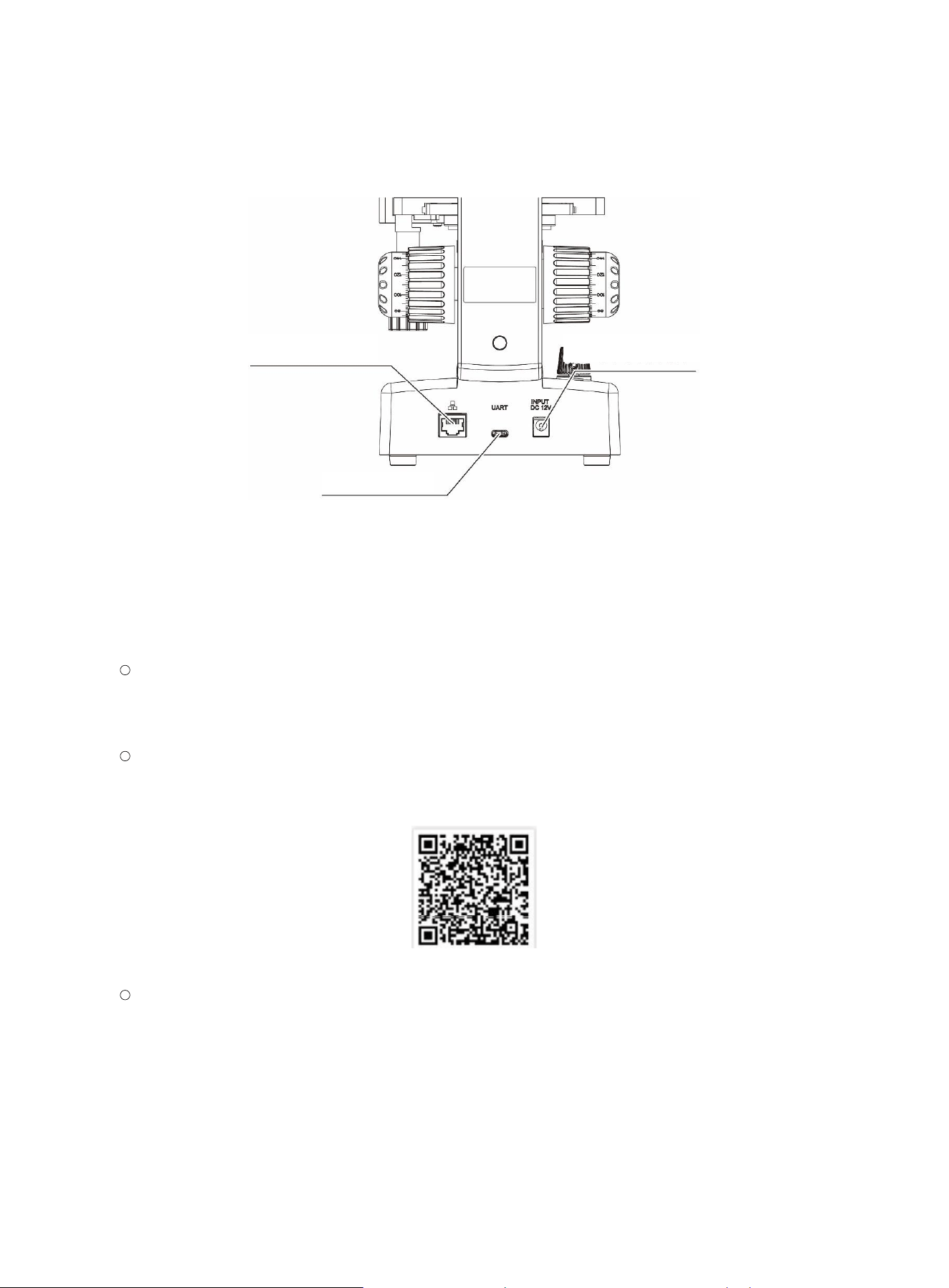
3.3.9 Extended Interface Functions
DC 12V general-purpose DC power interface, s upporting DC 12 V/2.5A in put from a powe r
adapter;
UART general-purpose USB-C interface, supp orting serial communication;
LAN general-purpo se w i red netw ork transmission interface, supporting w i red network
connection ;
100X objectiv
e
len
s
Cedar oil
Slid
e
15
(Figure 10)
3.4 Digital Microscopy Operation
3.4.1 Using the Software
When using MoticScope 1 through a Wi-Fi device running Android or iOS:
For optimal performance, we reco mmend using a Wi-Fi device with a screen size of no less than
8.7 in ches, such as a tablet. For iOS devices, we recommend iOS 16 or later; for Android
devices, Android 13.0 or l ater is recommended.
You can scan the fol l owing QR cod e with an Android or iOS Wi-Fi device to download and install
the free MotiConn ect application. For iOS Wi-Fi devices , you may also search for it in the App
Store to downlo ad and install it.
Connect your Android or iOS Wi-Fi dev i ce to the Wi-Fi network named SSID: MoticScop e 1
(select the corresponding model)_X XXXXX. The default initial password is 12345678 . After
establishing a wireless connection with the microscope, open the MotiConnect software, tap
the Settings ico n in the upper-right corner, add a camera name under Camera, and en t er the
URL address: 192.168.1 . 151. After adding it, the image will be displayed.
Wired network
interface
B
ase power input socket
UART interface
16
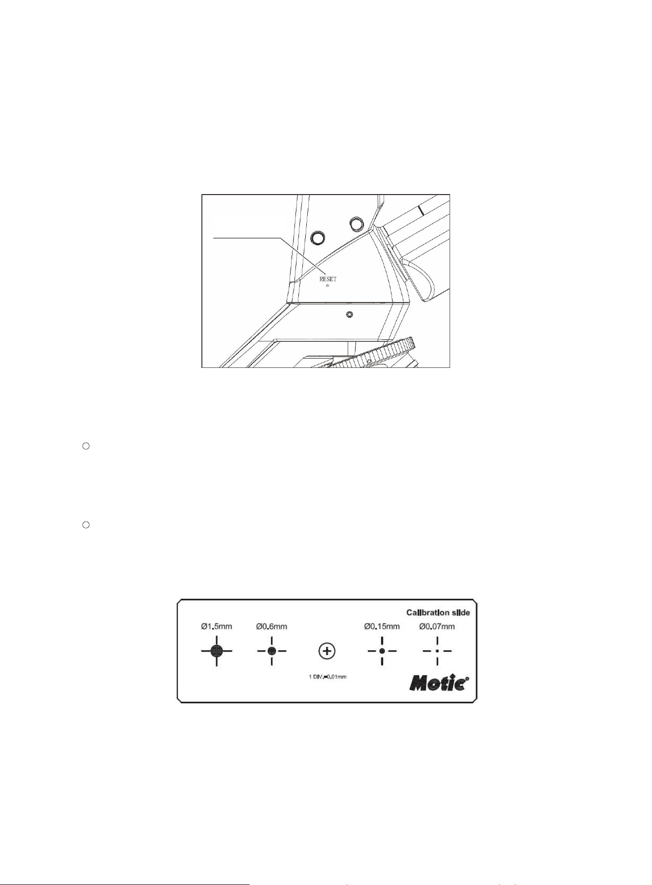
3.4.2 Reset
AM series mo dels support a digital re set fun ction. U se a 0.9 mm All en wrench, a paper clip, or a
similar tool to pre ss and hold the “RESET” hole for 8 seconds to restore the built-in digital camera to
its factory d efault settings.
(Figure 12)
3.4.3 Calibration
Switch the o bjective lens to be calibrated into the optical path, place the four-point calibration
slide (F i gure 13) on the stage, and follow the routine microscopic operat i ng procedure to bring
the calibration point into focus, ens uring that the v i sual calibration circ l e is clearly and complete l y
imaged within the field of view.
Open the Moti Connect software and select the calibration button. In the pop-u p window, click
the calibration button, load the magnificati on of the target obje ctive lens to be calibrate d and the
corresponding complete i mage of the standa rd circl e. Please read the so f t ware manual
carefully before operation.
(Figure 13)
R
ESET button

17
4. Maintenance and Care
Proper maintenance and servicing will ensure the microscope remains in reliable operation for a long
period without faults. If s ervice is requ i red, please c ontact your nearest Motic deal er or contact ou r
technical service department directly.
4.1 Cleaning
Eyepieces may be cleaned in the s ame manner as objective lenses, a nd in most cases it is not
necessary to use an optical cleaning agent. In most cases, breathi ng lightly onto the eyepiece will
mo
isten it; then use clean lens tissue to wipe the lens dry and ensure a clean surfac e.
Notes:
The m i xture of absolute ethan ol a nd ether is flammable. Do not use it in an environment with open
flames;
Do not touch the surface of optical components dire ctly, so as to avoid cont aminating the optical
surfaces;
Do not wipe a dry len s surface, other wise the surf ace or the lens may be scratched;
Do not use gauze or l ens paper to wipe the s ame area repeatedly;
After u sing ceda r oil, clean the front le ns group of the object i ve promptl y, espec i ally the 40x and
100x objectives;
Do not disassemble the objective lens yourself. If internal repair or cleaning of the objective lens is
required, please conta ct after-sales te chnical ser vice personnel. This operation may only be
performed by qualified and authorized technicians.
4.1.1 Optical Lens Surfaces
For cleaning optical lens surfaces and color filters, first use a rubbe r blower to remove surface dust.
If any dirt still remains, remove it with soft, cl ean gauz e or special optical lens paper .
Immersion oil contamination on the objective lens may only be removed with gauze or lens
paper moist ened with an appropriate amount of a mixture of absolute ethanol and ether (in a 3:7
ratio).
For lenses other than objective lenses, gauze or lens pape r moistened w i t h an appropriate
amount of a mixture of absolute ethanol and ether (in a 3:7 ratio) may be used to remove
fingerprints, grease, and othe r stains.

18
4.1.2 Surfaces of Painted Parts and Plastic Parts
Do not use organic solv ents (suc h as ethanol, ether, etc.) or th eir di l utions for cleaning.
Otherwise, the paint layer may fade or peel off.
The stubborn dirt can be wiped off by u sing gauz e that is dipped in sof t detergent.
The surfaces of plasti c p arts may only be cleaned with a soft cloth moistened with clean water .
4.2 Storage
Precaution s w hen this product is not in us e or is b eing stored:
When not in u se, the pow er switch should be turned o f f or the power plug should be unplugged, and
the in strument sh ould be prot ected with a dust cover to reduce the effects of dust.
For stora ge, t he 360° rotatable he ad may be turned 180° to reduce the depth footprint.
When stori ng models equipped with a mechanical stage, return the stage adjustment to the zer o
position to prevent damage from accidental impact.
Please ensure that sufficient storage space is available to avoid compression that may affect
product performa nce.
Do not store this product near chemicals, so as to avoid the effec t s of chemical corrosion.
If the produ ct will not be used for a long time , remo ve the objectiv e len ses, eyepieces, color f i l t ers,
and similar components, place them in a contain er with desicca nt, and fit the dust caps to prevent
dust contaminat i on.
4.3 Lamp Replace ment
Before replacing the lamp or batte ry, make sure that the power switch i s in the OFF position and
unplug the power cord.
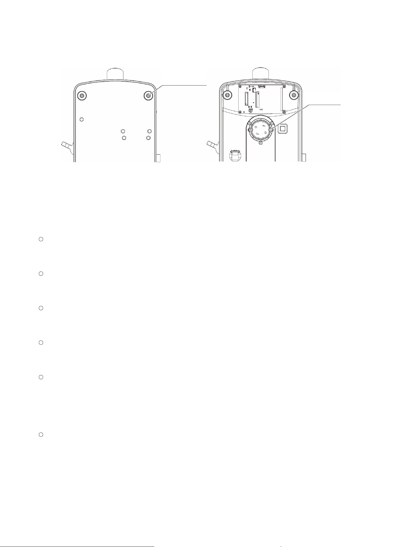
4.3.1 LED Lamp
Use a Phillips screwdriver to loos en the four fixing screws at the f oot pads of the bottom plate,
and remove th e bottom plate.
Use a Phillips screwdriver to loos en the fixing screws of the collector lens LED lamp assembly,
and remove th e LED lam p assembly.
Install the LED lamp assembly purchased from Motic (with the power connection wires soldered),
fit it into the c ollector lens LED lamp holder, and then reinstall it by reve rsing the steps ab ove.
When repl acing the l amp, not e that the center of the LED lamp assembly sho uld be adjust ed as
close as possible to the center of the collector l ens and the center of the optical ax i s.
Do not touch the surface of the LED chip directly wi t h your hands, so as to avoid fingerprints,
grease, and o t her contamination. If t here i s dirt on the surface of the LED chip, please clean it
according to Section 4.1.
19
(Figure 14-1) (Figure 14-2)
4.4 Maintenance Inspection
Maintenan ce interval for this product: ins pect the equipment once a year. Based on the characteristics of
the equipment, its service life, frequency of use, and failure rate, the responsible engineer shall submit a
specific report and make timely a djustments ac cordingly.
Appearance inspe ction: check whether any butt ons, switches, or knobs o n the equipment are loose
or misaligned; whether the plugs and sockets show oxidation, corrosion, or poor contact; whether
the power cord is aged; and whether all connecting cables are conne cted cor rectly.
Cleaning and maintenance: Clean the equipment surface and internal electrical and mecha nical
parts; clean the equipment plugs and prevent poor contact; appl y lubricant to the mechanical p arts if
necessary.
Functional inspection: pow er on the equipment and chec k whe t her all indicator lights and indicato rs
are functioning properly; enter each function setting mode, and by adjusting and setting the relevant
switches and buttons, check whether all functions of the equipment are o perating normally.
Performan ce test and calibration: Check if the Product's output error exceeds the relevant stand ards,
make n ecessary adjustment and calib ration to the parameters which exceed the standa rd ran ge, t o
ensure that the technical inde xes conform to the stand ard, and g uarantee the P roduct's quality.
Security check: I ncluding electrical se curity check and mechan i cal check.
① Electrical security ch eck: Check if the leading wires, plugs and conne ctors are dam aged, and
the grounding impedance an d leakage current are within th e standard range;
② Mechanical check: C heck if the mechanical component s are loose and have normal rotation,
and the conn ectors are loose, falling or cracked.
Personnel training m anagement: Organi ze technical training fo r operators regularly, to master the
equipment basic structure, basic prin ciple, perf ormance and functions, learn the equipment daily
maintenan ce metho d, master prop er use meth od and operation procedure, master the measures
and rel evant precautions of instrument security, and keep traini ng recor ds.
B
ottom plate fixin
g
s
crew
L
ED fixing screw
20
Appendix 1 Troubleshooting Table
Troubleshoot pro duct fau l t s ac cording to the table below . If you encounter a problem that cannot be
resolved, please contact your near est Motic dealer or contact our technical service depart ment d i rectly.
Optical Section
Fault Cause Solution
Dark edges in the field
of view or uneven
brightness across the
field of v i ew
The illumination device is not in stalled
properly or is out of alignment
Check and install the illumination
device correctly
The aperture diaphragm is too small
Adjust th e size of ap erture
diaphragm
The revolving n osepiece is not at fixed
position
Rotate the knob to the locating
position
The condenser position is too low Adjust th e condenser p osition
The condenser and objecti
ve a re
mismatched
Match the numerical aperture
There is dirt in the field
of view, and the image
is u nclear
The aperture diaphragm is opened too
little
Adjust and enlarge the aperture
diaphragm ope ning
There is dirt on the slide su rface Clean the s l i de surface
There is dirt on the optical surface Clean the optical surface
The condenser position is too low Adjust th e condenser p osition
Poor image quality (low
resolution, poor
contrast)
Brightness is too low or illumin ation is
incorrect
Check and use the original factory
lamp
There is no cover glass, or the
thickness is not standard
Use a specimen c over glass wi t h a
thickness of 0.17 mm
The aperture diaphragm does not
match the objective aperture
Adjust th e size of ap erture
diaphragm
The oi l -immersion objective is used
without oil, or ther e are air bubbles
Use the oil-i mmersion objective
correctly
There is grease on the eyepiece Clean the eyepiece
Uneven parfocal i t y (the The sli de specimen is not
flat Replace it with a specimen of

21
image plane is n ot flat) better flatness
The sli de specimen is not positioned
securely
Adjust th e slide to ens ure re l i able
positioning
The sli de holder is not securely
positioned on the stage
Adjust th e slide holder to ensure
reliable positioning
The stage surface is tilted
Report the issue to the technical
service department for handling
The bi nocular images
are not aligned
The in t erpupillary distance is not
adjusted correctly
Adjust th e interpupillary distance
co
rrectly
The eyes are overl y
fatigued
The di opter i s not adjusted correctly Adjust th e diopter correctly
The illumination brightness is not
suitable
Adjust th e illumination b rightness
Difference in th e field of view between
the le f t and right eyepiec es
Use eyepieces with the sa me field
of view
Out of focus after
focusing
The stage drifts downward
Adjust th e focus tension
adjustment knob
When switching the
objective from low
magnification to high
magnification, the
high
-power obje ctive
touches the slide
The specimen slide is inverte d or the
coverslip is too thick
Use a stand ard slide and place it
correctly
The di opter i s not adjusted correctly Adjust th e diopter correctly
The image is not
parfocal when switching
objectives
The di opter i s not adjusted correctly Adjust th e diopter correctly

22
Electrical Section
Fault
Cause
Solution
The illumination do es not
light up
The power is not connected
Check t he power p l ug
The power outlet is faulty
Replace the power outlet
The bulb is not installed properly
Check and install the bulb pr operly
The la mp is burned out
Replace the lamp
The illumination bri ghtness
is n ot suita ble
The unauthorized bulb is us ed Replace it with an auth orized bulb
The la mp has burned out
The unauthorized bulb is us ed
Replace it with an authorized b ulb
The illumination flickers
Poor contac t at the connection
position
Inspect and fasten the connection
The la mp has reache d the end of
its service life
Replace it with a new one
The la mp is not fully inserted into
the socket
Check and install the bulb pr operly

23
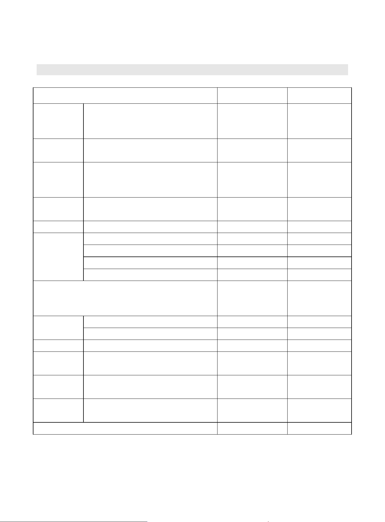
Appendix 2 Technical Specifications Table
Optical system Finite o ptical sys t em with achromatic correction
Total magnification 40X-1000X
Eyepiece 10X/18
Observatio n tube
45° monocular inclined tube with built-in
digital module (WiFi & UVC)
Achromatic objective lenses
4X/NA0.1/WD26.7
10X/NA0.2 5/WD5.4
40X/NA0.6 5/WD0.4 (spring-loaded)
100X/NA1. 25/WD0.15 (spring-loaded, oil)
Camera pixels 8MP
Sensor size 1/2.8 inch IMX415
Resolution / f rame rate
15 fps @ 38
40 x 2160
25 fps @ 1920 x 1080
Data s t ream protocol MJPG/H26 5
WiFi transmission 802.11ax
Menu Brightness, objective recognition, WiFi 6
Interface INPUT DC 12V × 1, UART × 1 (UVC), LAN × 1
24
Appendix 3 Product Configuration Table
Item N ame MoticScope 1 Single-unit quota
Arm
Assembly
Frame Assembly (Coaxial Co arse/Fine
Focusing, Four -Position Coded
Nosepiece , Includ i ng Auxiliary Objective)
● 1
Observatio n
head
Monocular digital head (WiFi 6) ● 1
Base
assembly
Base assembly (2.8-inch color LCD
touchscree n, 0.5 W f ull-spectrum LED,
digital dimming)
● 1
Stage
Mechanica l type (N.A. 1.25 condenser +
variable aperture diaphragm)
● 1
Eyepiece
WF 10X / 18
●
1
Objective lens
195B 4X achromatic objective ● 1
195B 10X achromatic objectiv e
●
1
195B 40X achromatic objectiv e ● 1
195B 100X achromatic objective
○
1
Switching powe r sup ply (12 V / 2.5 A, black
interchang eable main unit) (optimized conduction)
(including four country plugs)
● 1
Allen wrench
0.9mm
●
1
2.0 m m ● 1
Dust cover
Polyester_360*480
●
1
Objective dust
cap
WJ4/5 * 1/36 (RoHS) ● 4
Calibration
plate
Four-point calibration ● 1
User Manual
MoticScope 1 Biological Examination
Microscope_English_V 1 (RoHS)
● 1
Software_MotiConnec t Download Online 1
Motic Hong Kong Limited (Hong Kong)
Unit 1712, 17th Floor, Exchange Tower, 33 Wang Chiu Road, Kowloon Bay, Kowloon, Hong Kong
Tel: 852-2837 0888 Fax: 852-2882 2792
Motic Instruments Inc. (Canada)
130-4611 Viking Way, Richmond, B.C., V6V 2K9 Canada Tel: 1-877-977 4717 Fax: 1-604-303 9043
Motic Deutschland GmbH (Germany)
Christian-Kremp-Strasse 11 D-35578 Wetzlar, Germany Tel: 49-6441-210 010 Fax: 49-6441-210 0122
Motic Europe (Spain)
C. Les Corts 12, Pol. Ind. Les Corts. 08349 Cabrera de Mar, Barcelona, Spain Tel: 34-93-756 6286 Fax: 34-93-756 6287
Website: http://www.motic.com
E-mail: [email protected]
Motic China Group Co., Ltd. (China)
No. 810 Fangshan Nan Road, XiangAn, Xiamen 361100, P.R. China Tel: 86-0592-562 7866 Fax: 86-0592-562 7855
© 2007-2022 Motic China Group Co., Ltd. All rights reserved. Motic is a registered trademark and service mark of Motic China Group Co., Ltd.
Microsoft Windows logo is a registered trademark of Microsoft Corporation. All other trademarks are the property of their respective owners.
Design Change: The manufacturer reserves the right to make changes in instrument design in accordance with scientific and mechanical
progress, without notice and without obligation.
NO.: 1300901114821
Ver.1.0.0
Updated: 2026.03.23
(MoticScope 1)

FCC warning statements:
This equipment has been tested and found to comply with the limits for a Class
B digital device, pursuant to part 15 of the FCC Rules. These limits are
designed to provide reasonable protection against harmful interference in a
residential installation. This equipment generates, uses and can radiate radio
frequency energy and, if not installed and used in accordance with the
instructions, may cause harmful interference to radio communications.
However, there is no guarantee that interference will not occur in a particular
installation. If this equipment does cause harmful interference to radio or
television reception, which can be determined by turning the equipment off and
on, the user is encouraged to try to correct the interference by one or more of
the following measures:
• Reorient or relocate the receiving antenna.
• Increase the separation between the equipment and receiver.
• Connect the equipment into an outlet on a circuit different from that to which
the receiver is connected.
• Consult the dealer or an experienced radio/TV technician for help.
Caution: Any changes or modifications to this device not explicitly approved
by manufacturer could void your authority to operate this equipment.
This device complies with part 15 of the FCC Rules. Operation is subject to the
following two conditions: (1) This device may not cause harmful interference,
and (2) this device must accept any interference received, including
interference that may cause undesired operation.
The device has been evaluated to meet general RF exposure requirement This
equipment complies with FCC radiation exposure limits set forth for an uncontrolled
environment.
This equipment should be installed and operated with minimum distance 20cm
between the radiator & your body.