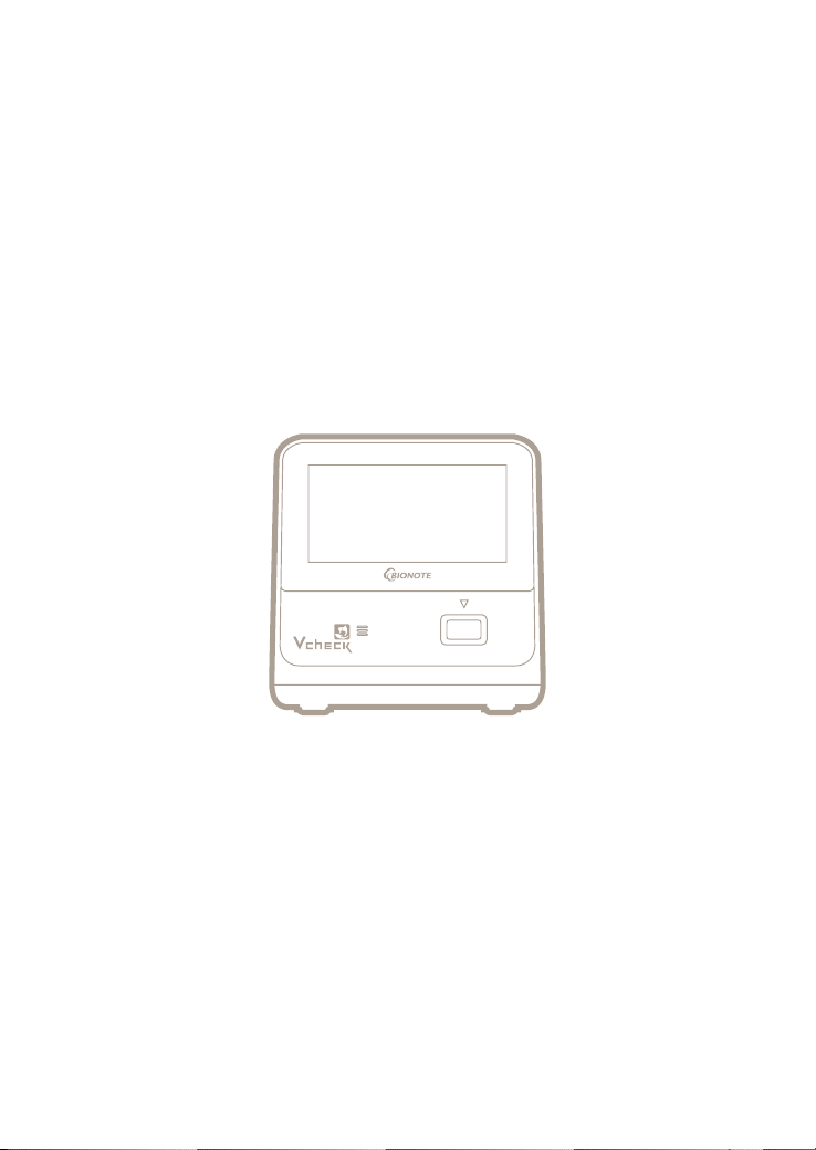
V200
FLUORESCENT IMMUNOASSAY SYSTEMS
USER MANUAL
FOR VETERINARY USE ONLY
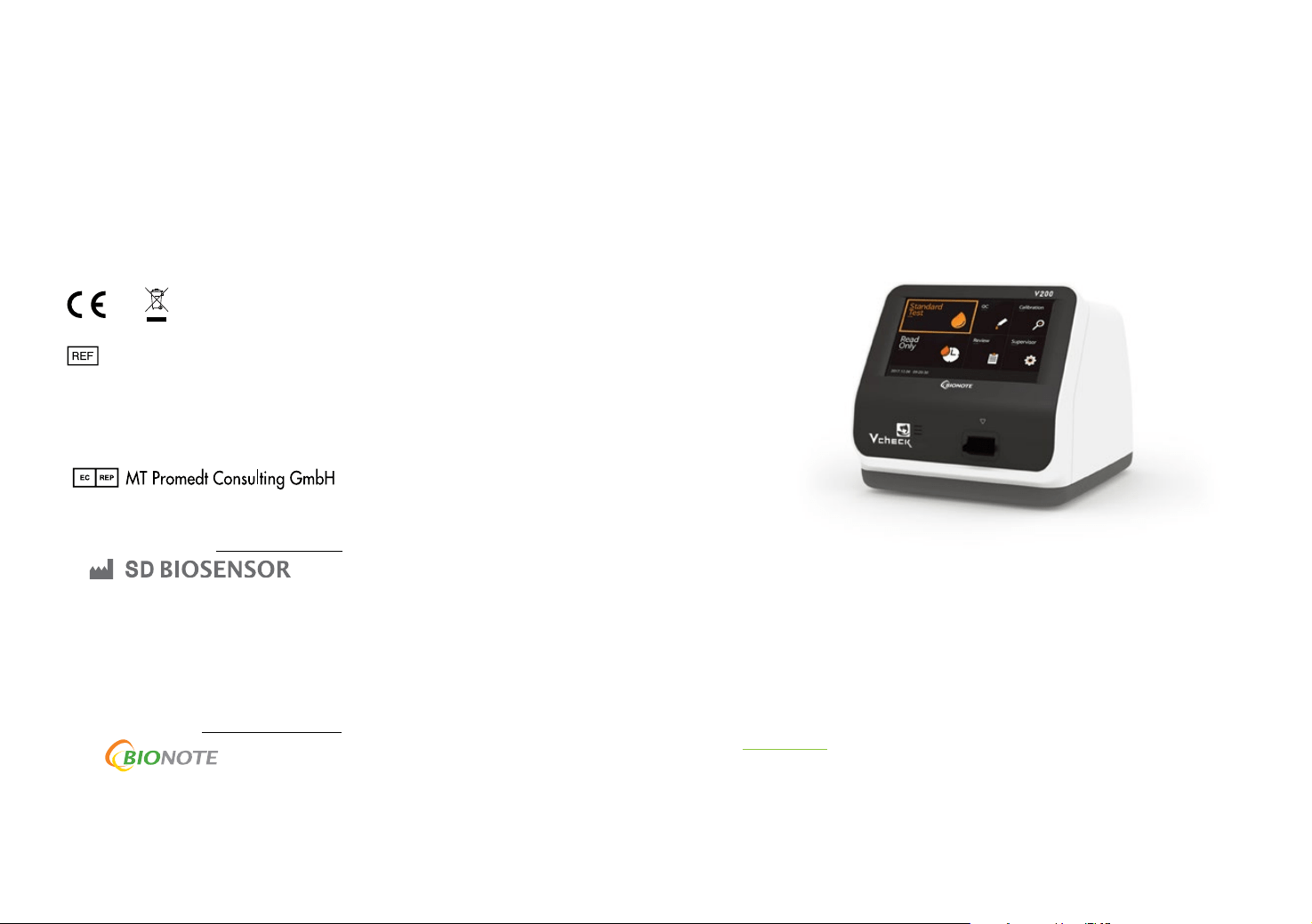
Thank you for your purchase of the BIONOTE V200
This user manual contains all the information needed to use the analyzer and keep it ready to operate. Please read this
user manual carefully before using the analyzer. Familiarize yourself with the required preparations and the measure-
ment procedure before performing the rst measurement. Please read the insert included in each test device package
before you try testing.
If you have any questions about the analyzer, please contact your healthcare professional or local distributor. You can also
visit www.bionote.co.kr for product demonstrations.
Thank you again for choosing the BIONOTE V200.
VC7402EA
Doc. No.: I7402-5E(CE)
Issued date : Sep. 17, 2019
Authorized Representative
Altenhofstrasse 80 D-66386 St. Ingbert Germany
Tel: +49-6894-581020 l Fax: +49-6894-581021
Manufactured by
Head oce
C-4th&5th, 16, Deogyeong-daero 1556beon-gil, Yeongtong-gu,
Suwon-si, Gyeonggi-do, 16690, Republic of Korea
Manufacturing site
74, Osongsaengmyeong 4-ro, Osong-eup, Heungdeok-gu,
Cheongju-si, Chungcheongbukdo, 28161, Republic of Korea
Tel: +82-31-300-0400 l Fax: +82-31-300-0499
www.sdbiosensor.com
Distributed by
22, Samsung 1-ro 4-gil, Hwaseong-si, Gyeonggi-do 18449,
Republic of Korea
Tel: +82-31-211-0516 l Fax: +82-31-8003-0618
www.bionote.co.kr

TABLE OF CONTENTS
CHAPTER 01. General Information
Main Menu Structure ........................................................................................................................................ 6
Symbols and Abbreviation .............................................................................................................................. 10
Brief Precautions and Limitations...................................................................................................................12
CHAPTER 02. Introduction
Intended Use ...................................................................................................................................................13
Product Description ......................................................................................................................................... 13
Before You Start Testing .................................................................................................................................. 13
System Components ....................................................................................................................................... 15
CHAPTER 03. Settings and Performance
Operating the Analyzer ................................................................................................................................... 19
Performing a Measurement ........................................................................................................................... 34
CHAPTER 04. Using the Analyzer Memory and Data Transfer
Displaying Stored Measured Values................................................................................................................41
Send Results .................................................................................................................................................... 42
CHAPTER 05. Quality Control
Control Test ...................................................................................................................................................... 44
How to Perform Quality Control ..................................................................................................................... 45
CHAPTER 06. Calibration
Calibration Set Test .......................................................................................................................................... 48
How to Use the Calibration Set Test ................................................................................................................ 49
CHAPTER 07. Cleaning and Maintenance
Cleaning the Analyzer ..................................................................................................................................... 52
Maintenance and Transportation ................................................................................................................... 52
CHAPTER 08. Screen Messages and Troubleshooting
Warning Messages ..........................................................................................................................................53
Error Messages ................................................................................................................................................55
CHAPTER 09. On-Line Update Conguration
Wireless LAN Connection Settings ................................................................................................................. 58
ANNEX 01. Information for Healthcare Professionals
Protection against Infections ......................................................................................................................... 64
ANNEX 02. Reference
Warranty ......................................................................................................................................................... 64
Return ............................................................................................................................................................. 65
Disposal ...........................................................................................................................................................65
6 7
CHAPTER 01. General Information
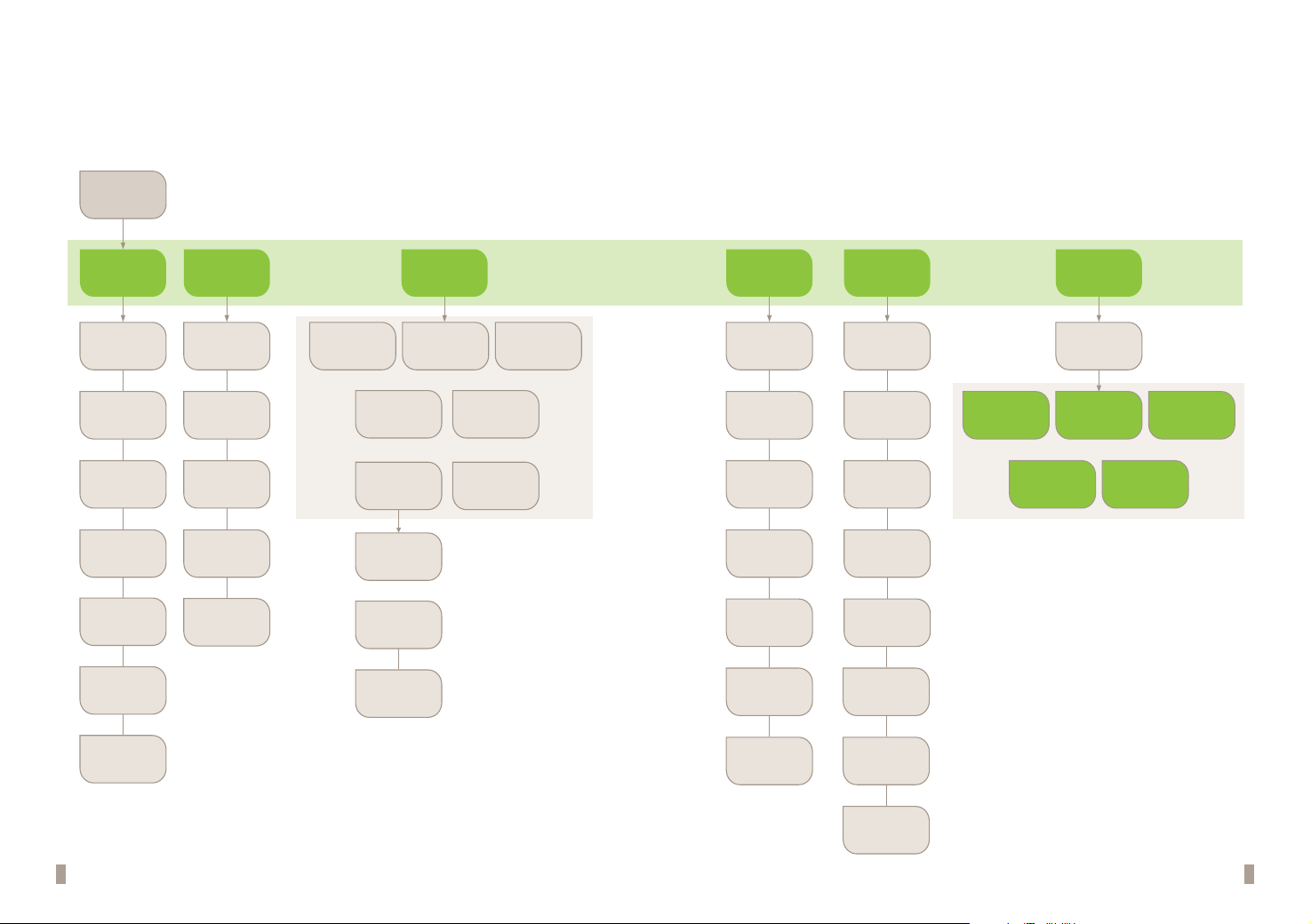
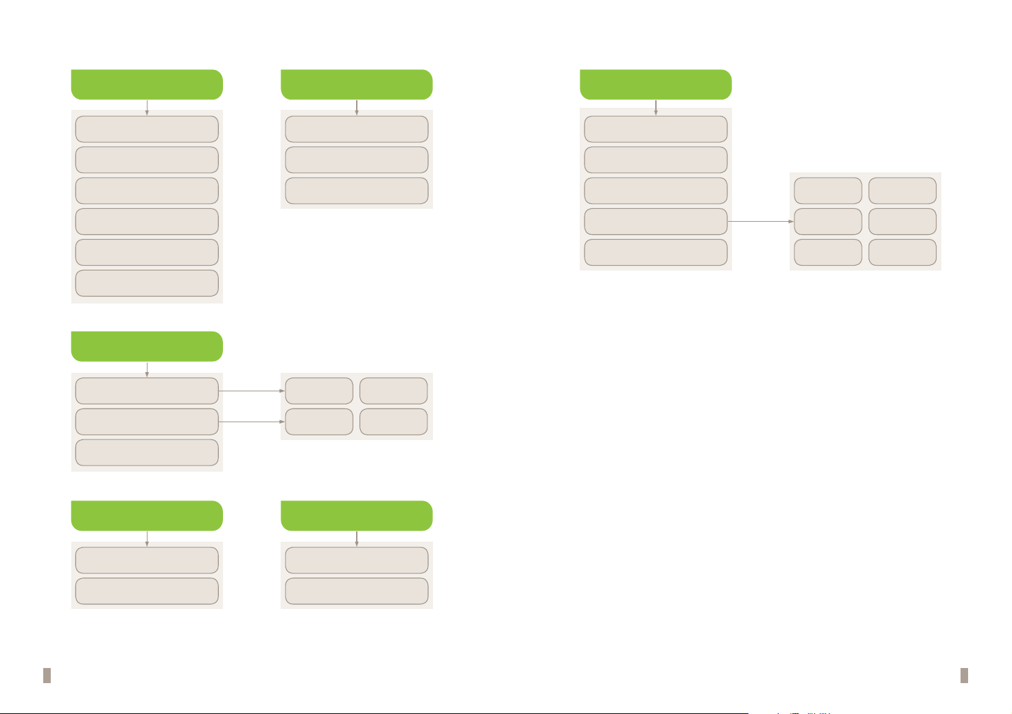
Main Menu Structure
Main
Standard Test Q.CRead Only CalibrationReview Supervisor
Login LoginLogin Login
Calibration
Results
Password
Load/
Save
Select
Setting
Q.C
Result
Update
Send
Results
Detailed
Results
Search
Info
Patient
Results
Manage
Operator
Insert Device Insert DeviceInsert Device Insert Device
Insert Device
Device Check Device CheckDevice Check Eject Device
Eject Device
Apply Sample Apply Sample
Analyze
Sample Check
Finish
Select All
Sample Check
Delete
Analyze
Delete All
Analyze
Insert Device
Analyze
Finish
Finish
Finish
8 9
Send Results Settings
Load / Save
Update Info
Manage Operator
Send Unsent Result Set Print Option
Settings Load Save
S/W Update View Version
Add
Send All Q.C Results Set Calibration and Q.C
Save Test Records
Delete
Send All Patients Results Instrument Name
Send All Results Set Timeout
Operator ID Load Save
F/W Update View Network
Edit
Send Last Results General Settings
Send Selected Result
Date/Time Language
Units
LIS
Parameters
Network
Volume/
Brightness
10 11
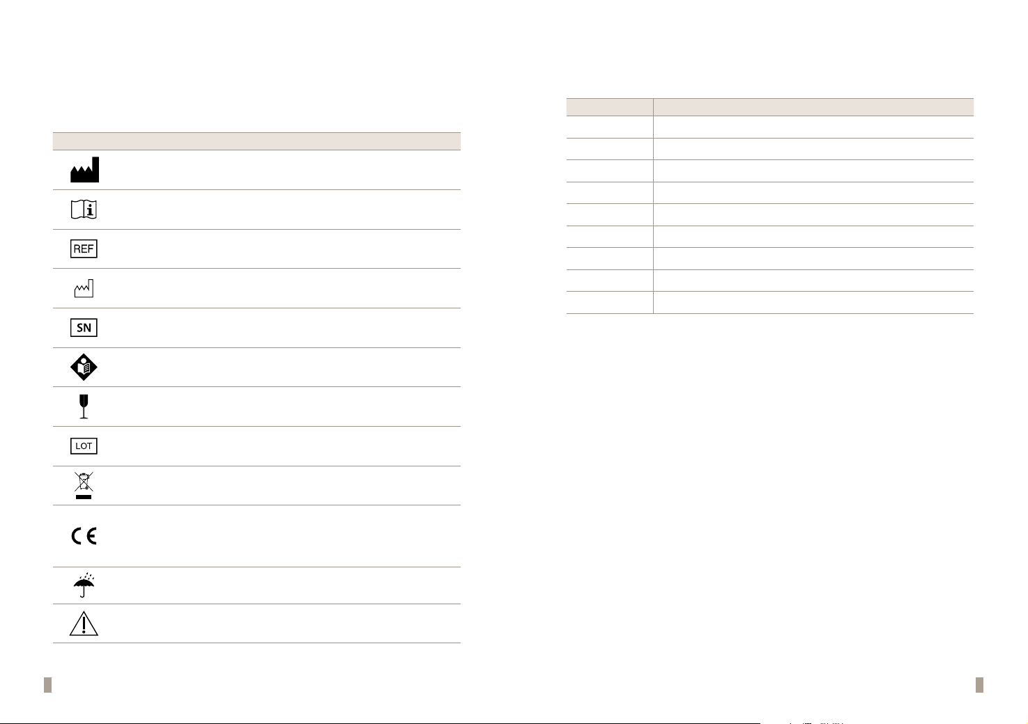
Symbols and Abbreviation
Symbols
These symbols and abbreviations may appear on the packaging, on the labels, and in the instructions for the
BIONOTE V200.
Symbol Description
Manufacturer
Consult instructions for use
Reference number
Date of manufacture
To indicate the date of analyzer manufacture
Serial number
Note
Indicates that the product is fragile and to handle it with care
Batch code
To indicate the lot number
Indicates to discard it separately from other household waste
This product fullls the requirements of European Low Voltage Directive 2014/35/EU (Low Voltage
Directive, LVD), Electromagnetic Compatibility Directive 2014/30/EU (EMC Directive), RoHS Directive
2011/65/EU
Indicate that you should keep the product dry
Caution!
Indicate a situation, which if not avoided could result in damage to the analyzer or incorrect results
Abbreviation
Abbreviation Description
cCRP
Canine C-Reactive Protein
fSAA
Feline Serum Amyloid A
Comm
Communication
LIS
Laboratory Information System
HIS
Hospital Information System
GUI
Graphic User Interface
S/W
Software
F/W
Firmware
BN
BIONOTE, Inc.

12 13
Brief Precautions and Limitations
Caution
To reduce the risk of analyzer damage
· Keep the BIONOTE V200 analyzer on a at and dry surface
· Avoid direct sunlight when operating the analyzer
· The analyzer has an internal adjustment for normal ambient light conditions, but
highly intense light entering the analyzer may cause signicant interference with the
results and must be avoided
· Do not attempt to disassemble the analyzer
· Do not immerse the analyzer in water or cleaning solutions
To reduce the risk of incorrect results
· Only trained operators should use the analyzer
· Using expired test devices may cause inaccuracy of the results.
· Do not use if the analyzer is displaying an error message which cannot be corrected
· To obtain accurate results, refer to the test device package insert for test storage and
system operating conditions
Potential
Biohazard!
To reduce the biohazard risk
· The used test and all specimens should be discarded as biohazard waste and must be
handled according to local regulations.
· Handle all specimens with caution as if they contain infectious agents.
· Seek appropriate training or refer to the instructions if you are not experienced with
collecting and handling specimens
· Wear personal protective equipment, such as gloves and lab coats, when handling
the specimen and kit reagents. Wash hands thoroughly after the test.
CHAPTER 02. Introduction
Intended Use
The BIONOTE V200 analyzer eciently tests quantitative or qualitative biomarkers in the laboratory and point-
of-care settings using the body uid parameters. The analyzer is to test and diagnose in clinical settings by
healthcare professionals. The analyzer should only be used with the test device produced by BioNote. For more
information on each specic test, refer to the assay-specic package insert.
Product Description
The BIONOTE V200 analyzer automatically recognizes the lot of the inserted test device by reading its 2D
barcodes. Once the test device is inserted into the BIONOTE V200 analyzer, UV or RGB LED (light-emitting
diode) illuminates the test device's application well through scanning. The type of light used determines how
the test device should be analyzed before performing the actual measurement. An enzymatic reaction occurs
when the specimen is applied, forming a dye and the amount of formed dye is proportional to the analyte
concentration. The intensity of the visual color or uorescence can be measured by illumination with motor
and LED, and detected by the reectance photometry. The measured value considers the light's signal power,
a blank value measured, and information read, including 2D barcode data. As a nal step, the test result is
displayed on the screen and stored simultaneously in the analyzer's memory.
Before You Start Testing
Note
Read and follow the instructions carefully in the user’s manual and the instructions to use the test
device and control. It is crucial to follow the instructions to prevent incorrect results or improper
treatments.
Specimens
The BIONOTE V200 analyzer should only be used with specific test devices for the analyzer. Follow the
instructions for each test device insert because each specimen is dierent for each parameter.
Safety information
Due to a potential risk of infection, healthcare professionals using the BIONOTE V200 analyzer should wear
protective equipment and follow local health and safety regulations.
14 15
Operating conditions
To ensure a proper function of the BIONOTE V200 analyzer, refer to the following guidelines:
· The BIONOTE V200 analyzer is recommended to be used at 15 ~ 30
o
C.
· Operate the analyzer only within the acceptable environmental conditions. The acceptable temperature
range varies depending on each reagent.
· To perform a measurement, place the analyzer on a at surface.
· Strong electromagnetic elds may aect the functions of the analyzer. Do not use the analyzer close to
sources of intense electromagnetic radiation.
· The analyzer's air vents must be free for ventilation (Do not cover the air vents).
· Unplug the adapter from the outlet in case of a sudden malfunction with the analyzer.
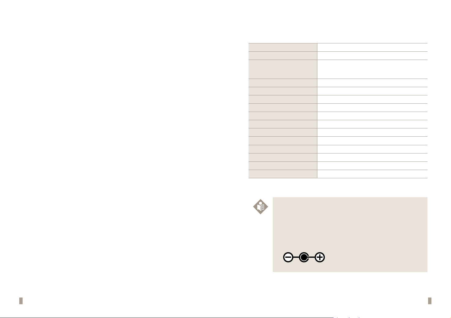
System Components
After unpacking the shipping container, inspect the unit and components for damage.
Analyzer
BIONOTE V200 Analyzer
Calibration Set
BIONOTE Vcheck Calibration Set
DC Power Supply
Input: AC100~240V, 50/60Hz
(Voltage tolerance ±10%)
Output: DC12V/5A
Display
7" Color TFT LCD (800x480)
Display Controls
Graphical User Interface
Power Consumption
Max 60W
Over Voltage Category
Ⅱ
Pollution Degree
Ⅱ
Memory
2000
RTC
RTC Backup Battery Included
Size
214.9 x 261 x 203 mm
Labeling
User Manual
Barcode Scanner (Optional)
Barcode Scanner
LAN transfer rate (bps)
100M
LAN cable
CAT 5
Note
· BioNote does not supply the AC/DC power adapter. All users must use an approved adapter.
(VDE, UL, TUV, etc.)
· Do not connect to the power supply other than the specied AC/DC adapter rating.
· The size of a jack that connects with the DC power adapter is 5.5 mm (external diameter) and
2.5 mm (internal diameter).
· All users must check the adapter polarity before plugging the adapter into the device.
16 17
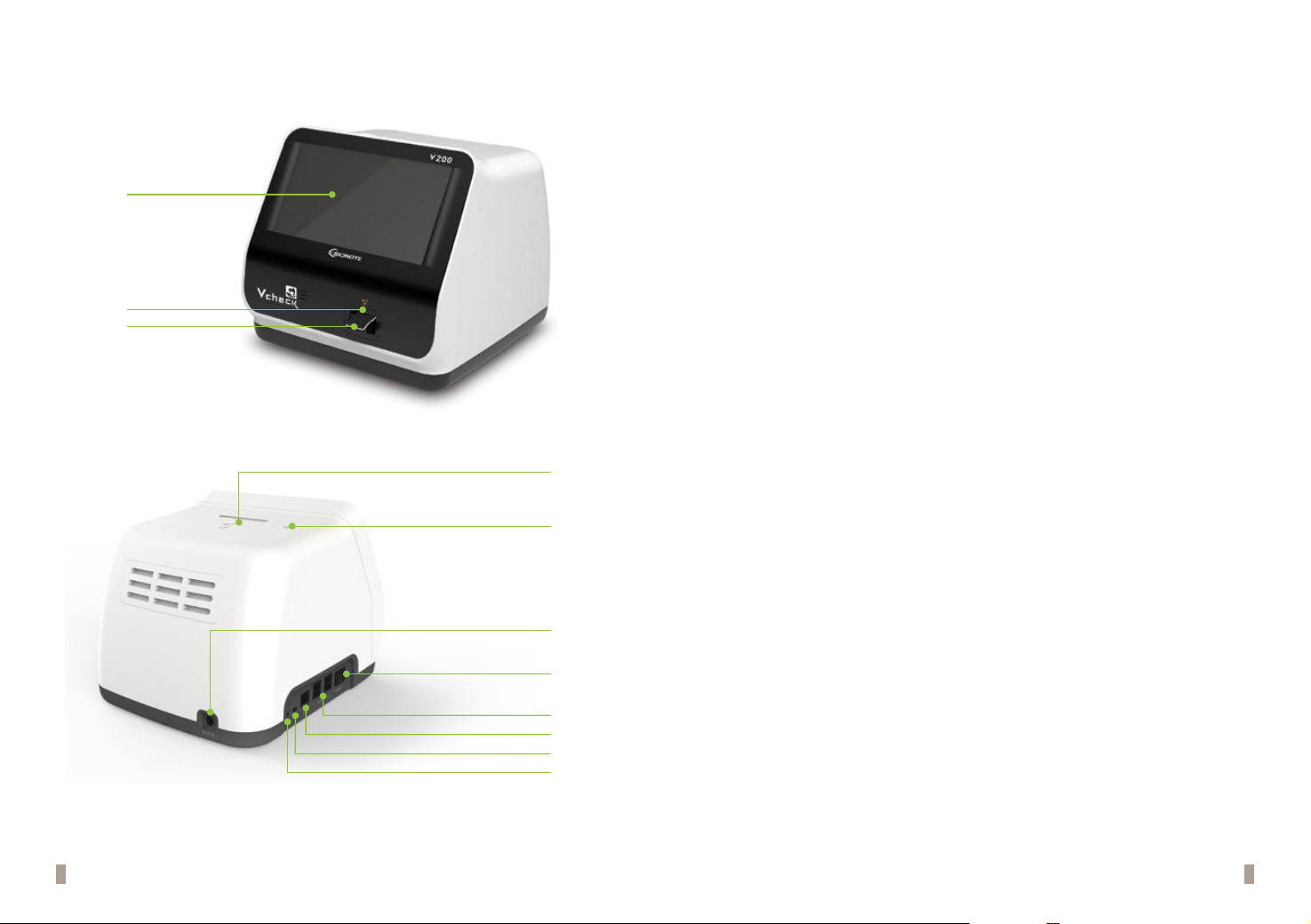
Overview of BIONOTE V200 analyzer
A
B
C
E
G
H
I
J
K
D
F
A. Color TFT LCD
Use for displaying the test screen and interacting with the graphical user interface
B. Test Slot
Slot for inserting a test device into the analyzer
C. Test Device
Use for initiating the test by inserting the specied test device
D. Printer Cover
Use for covering and protecting the printer sheet
E. Printer Cover Button
Use for opening the printer cover
F. DC Jack Port
Use for connecting the power supply adapter 12V/5A to its compartment
G. Power switch
Use for turning on/o the analyzer
H. USB x 4
Use for connecting the keyboard, barcode scanner, and USB drive
I. LAN
Use for communicating through the local area network
J. Mini USB
Use for upgrading the F/W upgrade by connecting to a PC
K. Additional Device Port
Use for connecting to specic devices manufactured by BioNote, Inc.
18 19
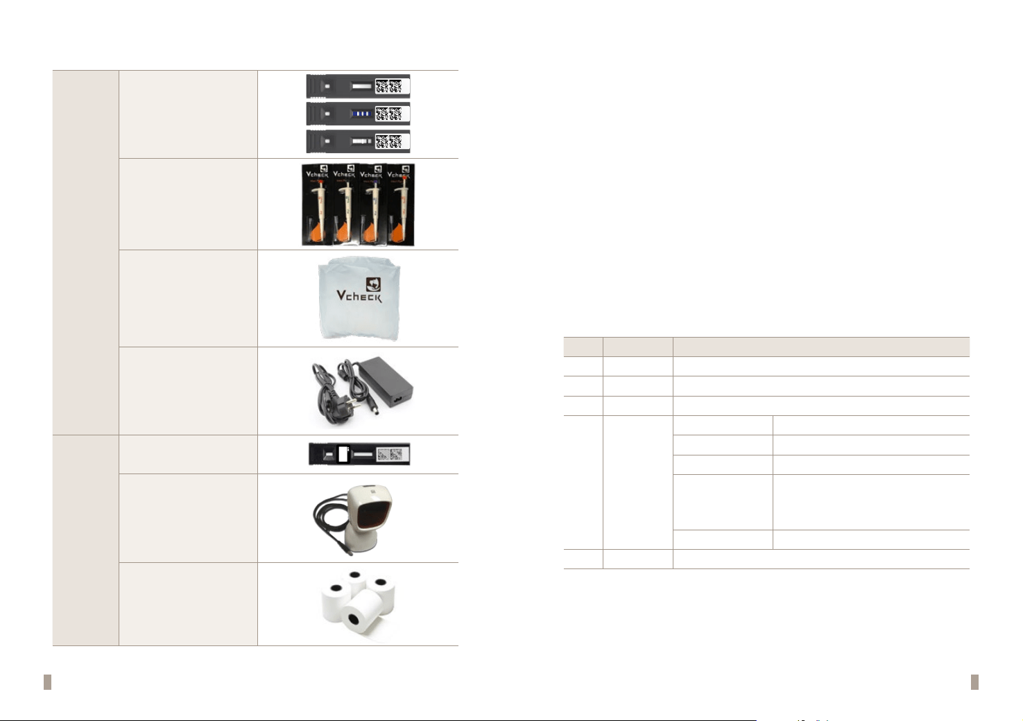
Accessories of the BIONOTE V200 analyzer
Included
Calibration set
CAL-1 CAL-2 CAL-3
Pipette Set
Protection cover
12V/5A AC/DC
power adapter
Optional
Test device
Barcode scanner
(For patient ID recognition)
Print paper
(57mm width Thermal paper is used)
If a smaller paper is used, the "No Paper"
error message may be displayed due to
sensor malfunction.
CHAPTER 03. Setting and Performance
Operating the Analyzer
STEP 1. Connect AC/DC adapter jack
1-1 Place the analyzer to a suitable location for testing, within reach of an electrical outlet.
Ensure the located surface is stable, at, and dry. Ensure there is adequate space for the
analyzer and barcode scanner stand.
1-2 Plug the DC power cord into the power port in the back of the analyzer. Plug the country-
specic AC/DC adapter power cord into an available electrical outlet.
1-3 The analyzer is ready for use once the connection is complete.
STEP 2. Setup the analyzer
2-1 To turn on the V200 analyzer, press the power button located on the side of the analyzer
for 3 seconds.
2-2 Register the operator's ID when setting up the analyzer for the first time. The initial
supervisor password is 0000.
2-3 It is recommended to acknowledge the table presented on the supervisor menu.
Stage Menu Sub menu
1 Manage Operator Add / Edit / Delete
2 Load/Save Settings / Operator ID / Save test records
3 Update F/W update, S/W update
4 Settings
Print option Printed sheet 1/Printed sheet 2/Auto-printing
Time out Automatic turn-o time /Insert test device time
Calibration & Q.C Time period
General
Date/Time/Language/Units/Network/LIS/Volume/
brightness
※
LIS/HIS can be set only when LIS/HIS server and
connection is ready.
Instrument name Instrument name/Facility name
5 Info View version / View network
20 21
1st step: Conguring the setup mode
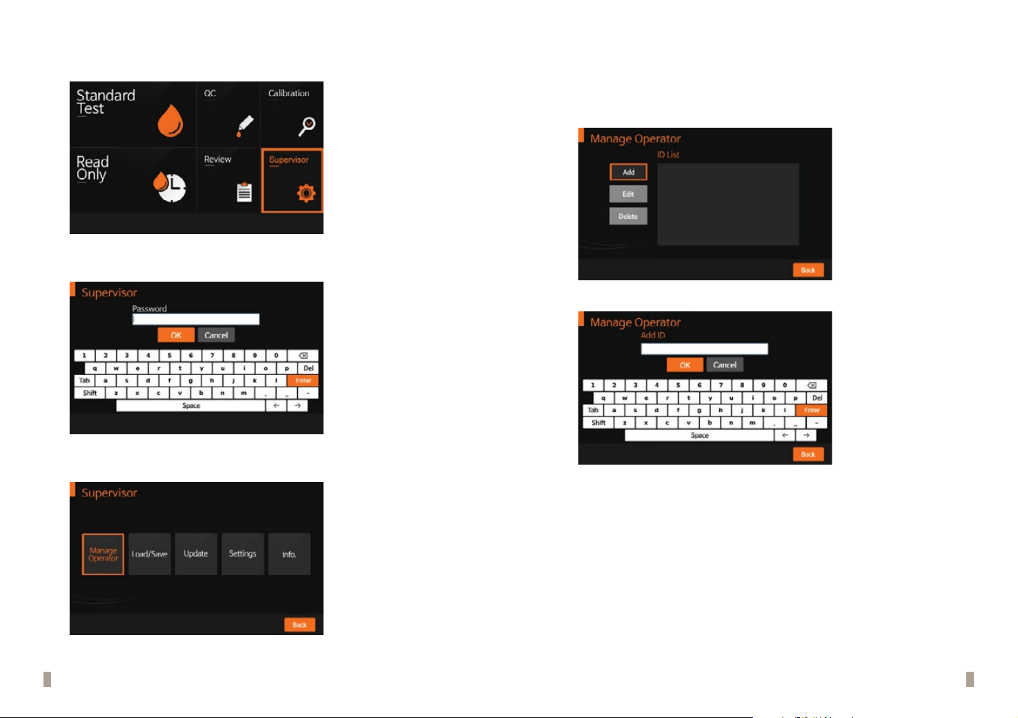
1. Select 'Supervisor' on the screen in the main menu to congure the setup mode.
2016. 10. 26 l 16:18:57
2. Input the password and press 'OK'. The initial password is 0000. Press 'Cancel' if you want to return to the
previous setting.
2016. 10. 26 l 16:19:00
3. The supervisor menu allows the operator to access and personalize additional functionality and security
options.
2016. 10. 26 l 16:19:03
2nd step: Supervisor>Manage Operator
1. Select 'Manage Operator' on the screen to add, edit, or delete the operator's ID. Press 'Back' if you want to
return to the previous setting.
2. To add the operator's ID, press 'Add'. Use the touch panel keyboard or a USB connected keyboard to add
the operator's ID.
2016. 10. 26 l 16:19:13
3. Press 'OK' to conrm the ID addition. The added operator's ID will be registered in the analyzer.
BIONOTE
2016. 10. 26 l 16:19:20
22 23
3rd step: Supervisor > Load/Save
Note
The software including GUI can be updated by USB memory, and the rmware can be updated by
mini USB with PC connection. The USB can be connected whenever the analyzer’s power is on.
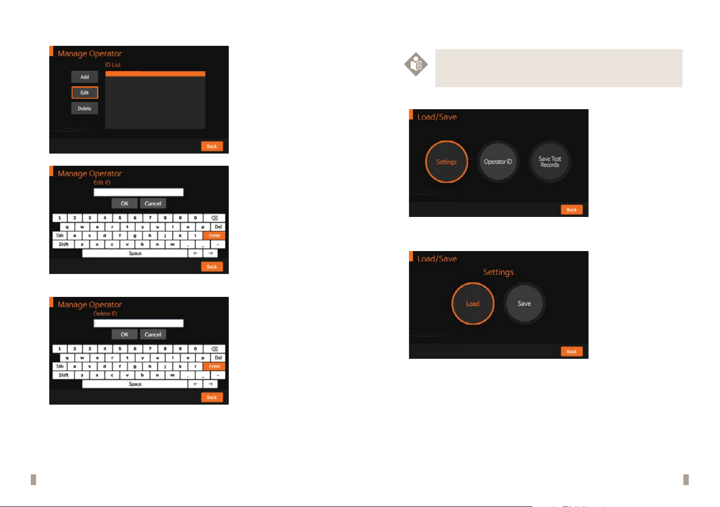
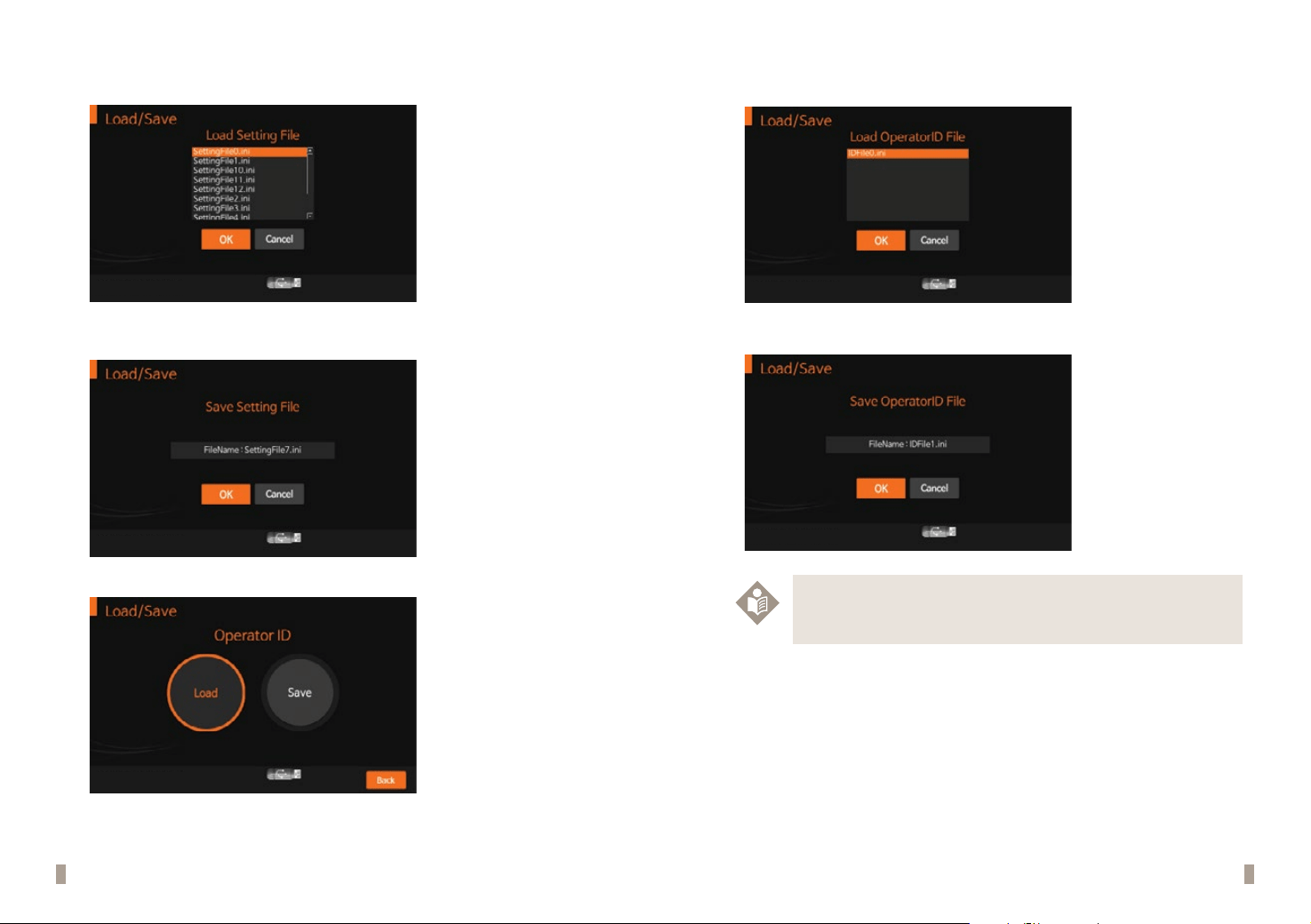
1. From the Supervisor menu, press 'Load/Save'. Then press 'Settings' to proceed to the next step.
2016. 10. 26 l 16:19:40
2. Press ‘Load’ to load the analyzer data according to the test type. This can be done by inserting the USB
device containing data that can be loaded into the analyzer.
2016. 10. 26 l 16:19:45
4. Press 'Edit' to edit the currently registered operator's ID.
BIONOTE
2016. 10. 26 l 16:19:24
BIONOTE
2016. 10. 26 l 16:19:30
5. Press 'Delete' to delete the currently registered operator's ID.
BIONOTE
2016. 10. 26 l 16:19:35
24 25
3.
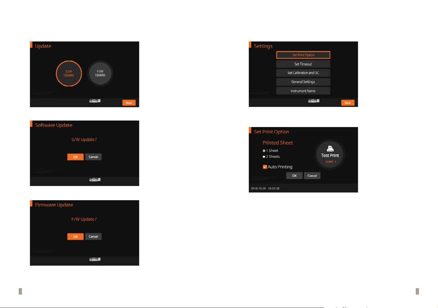
After appropriate data has been loaded, ‘Loading Setting File’ message indicating a successful data load will
be shown. Press ‘OK’ to conrm.
2016. 10. 26 l 16:19:50
4.
To save analyzer settings that have been duplicated from another device settings, press ‘Save’. Press ‘OK’ to
conrm after the data save procedure is completed.
2016. 10. 26 l 16:19:54
5.
To load the saved operator’s ID, press ‘Load’.
2016. 10. 26 l 16:19:58
6. After the operator's ID has been loaded, ‘Load Operator ID File’ message indicating a successful operator's
ID has will be shown. Press ‘OK’ to conrm.
2016. 10. 26 l 16:20:00
7. To save the operator's ID le, press ‘Save’. Then press ‘OK’ to conrm.
2016. 10. 26 l 16:20:03
Note
The analyzer’s test results may be exported and saved to a USB drive. Saved data can be managed
by the supervisor and all records of the test results can be displayed and printed.
26 27
4th step: Supervisor > Update
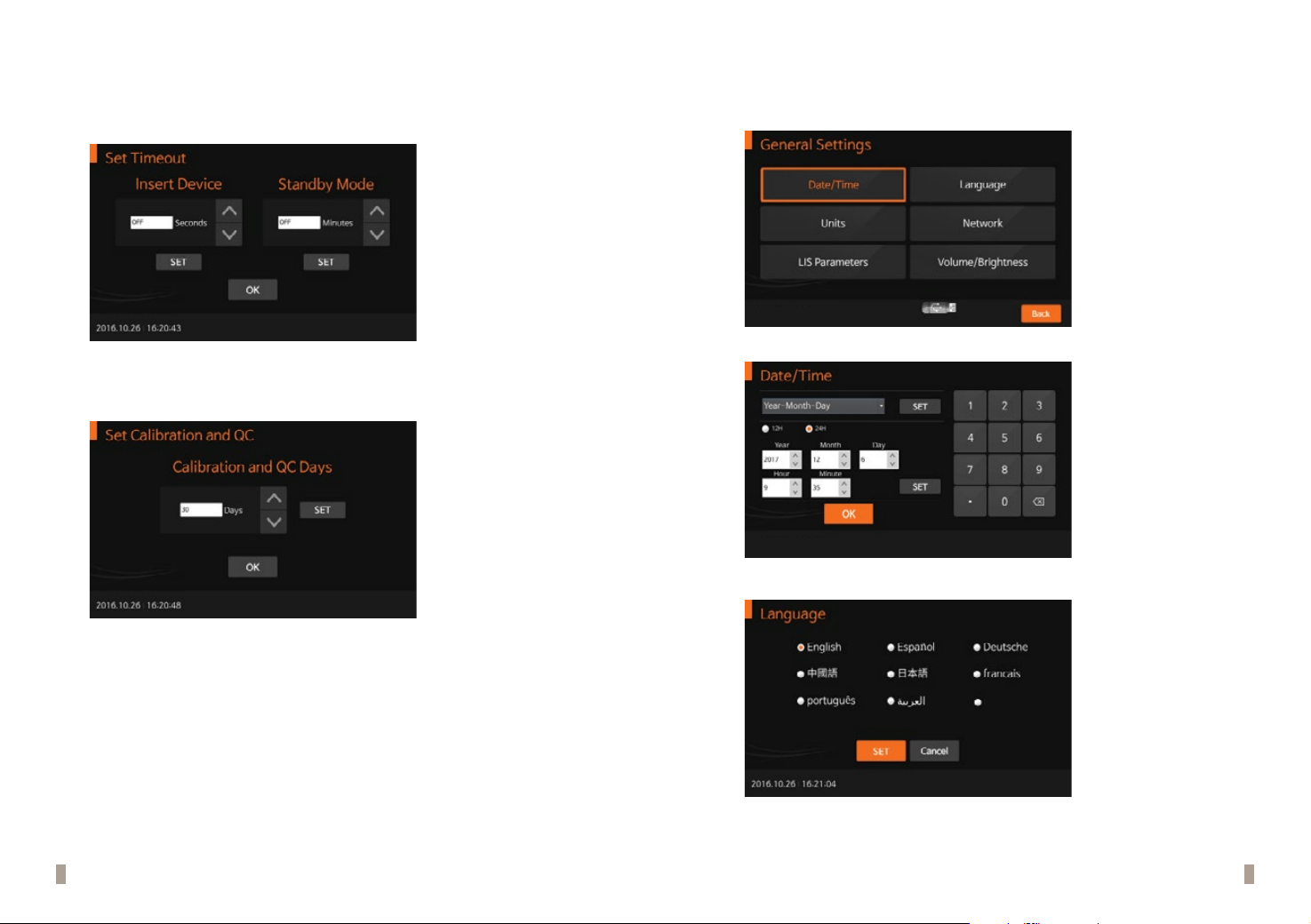
1. To update the analyzer's software or rmware, press ‘Update’ from the 'Supervisor' menu after connecting
the USB device containing the S/W or F/W update.
2016. 10. 26 l 16:20:08
1-1. Press ‘OK’ to update the new analyzer software. The analyzer will read the new software to be installed.
2016. 10. 26 l 16:20:15
1-2.
Press ‘OK’ to update the new analyzer rmware. The analyzer will read the new rmware to be installed.
2016. 10. 26 l 16:20:18
5th: Supervisor > Settings
1. To set the print option, automatic turn-o time, calibration, QC date, general settings, or instrument
name, press ‘Settings’. Press ‘Back’ to return to the previous menu.
2016. 10. 26 l 16:20:25
2.
To set the number of printed sheets as 1, 2, or auto-printing mode (ON/OFF), press ‘Set Print Option’. Check
‘Auto Printing’ to automatically print all test results at the end of each test.
28 29
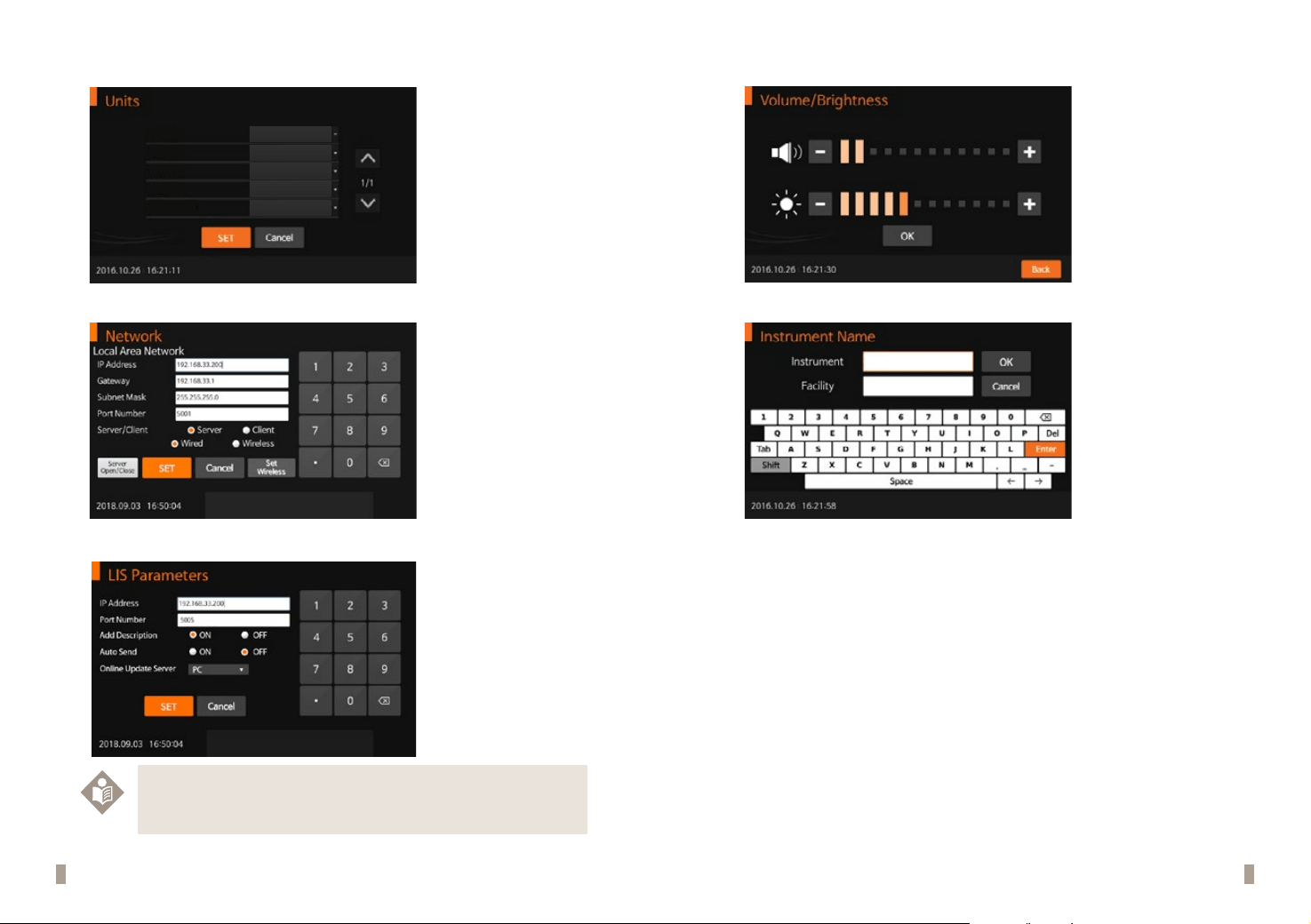
3. To control the analyzer's automatic turn-o time for power saving, press 'Set Timeout'. 'Insert Device'
allows users to set the appropriate timeout value for inserting a test device. If the user passes the set
value, the previous test procedure will be displayed. 'Standby Mode' allows users to set the appropriate
timeout value for the whole device. If the user passes the set value, a screensaver will be displayed.
4. To set the time for calibration and QC, press ‘Set Calibration and QC Days’. After the calibration and QC
procedure is completed, the analyzer will check the QC date and activate an alarm to indicate the number
of days since the last QC.
5. To set the date/time, language, test unit parameters, network, LIS parameters, sound volume, or LCD
brightness, press ‘General Settings’. Test parameters corresponding to the test type can be set under the unit
settings, and the parameters can be adjusted by updating the analyzer software.
2016. 10. 26 l 16:18:57
<Setting the date/time>
2016. 10. 26 l 16:20:58
<Setting the language>
język polski
30 31
<Setting the test parameter's unit>
Canine CRP
fSAA
㎎/L
㎍/㎖
cPL
fPL
cCortisol
ng
/㎖
㎍/L
㎍/dL
<Setting the network>
<Setting the LIS parameter>
Note
Consult a technician for the network settings information or for the LIS parameters.
<Setting the sound volume/LCD brightness>
<Setting the instrument name>
V200
32 33
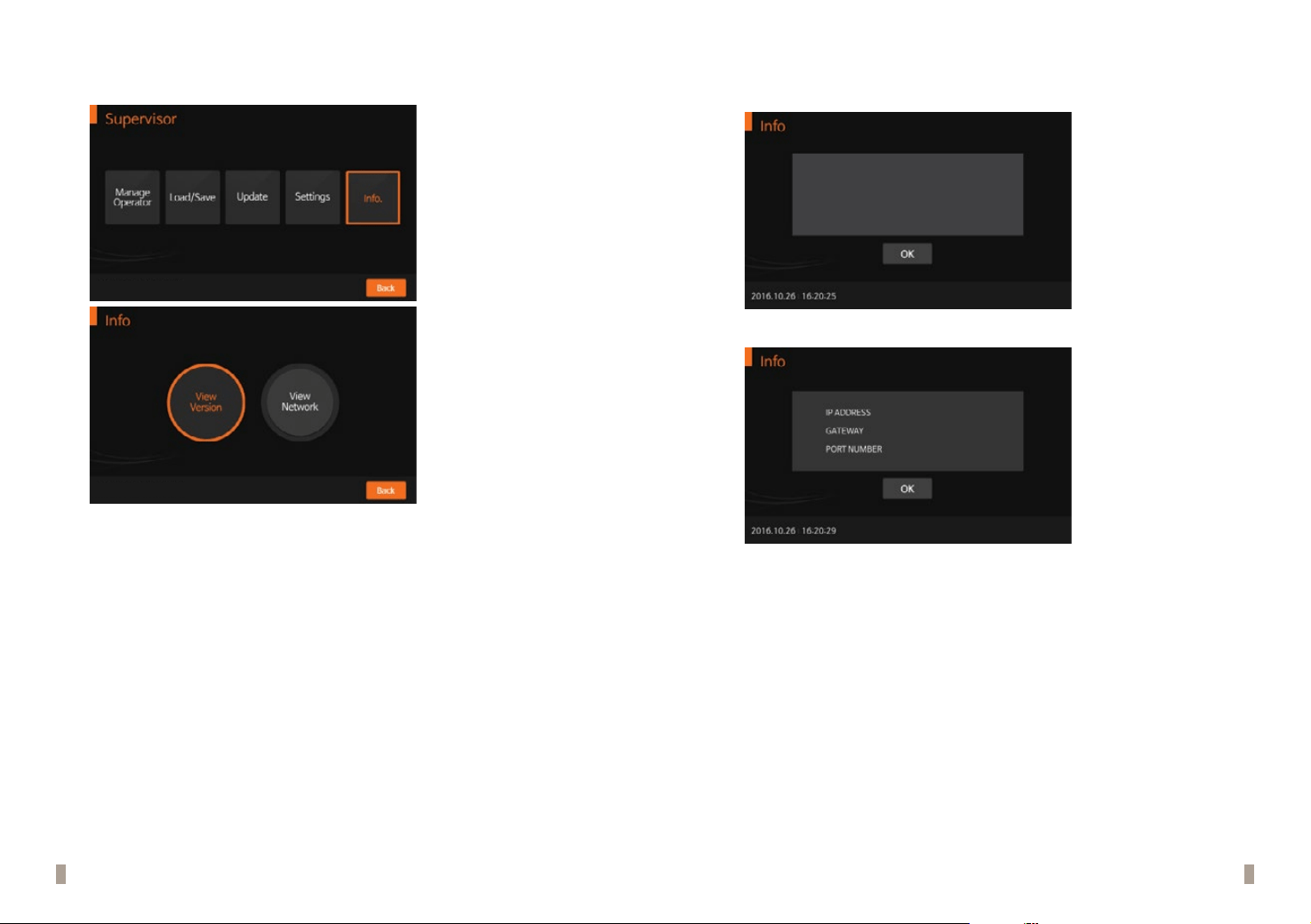
6th: Supervisor > Info
1. To display and view the analyzer's current software version, rmware or network, press ‘Info’.
2016. 10. 26 l 16:22:30
2016. 10. 26 l 16:23:10
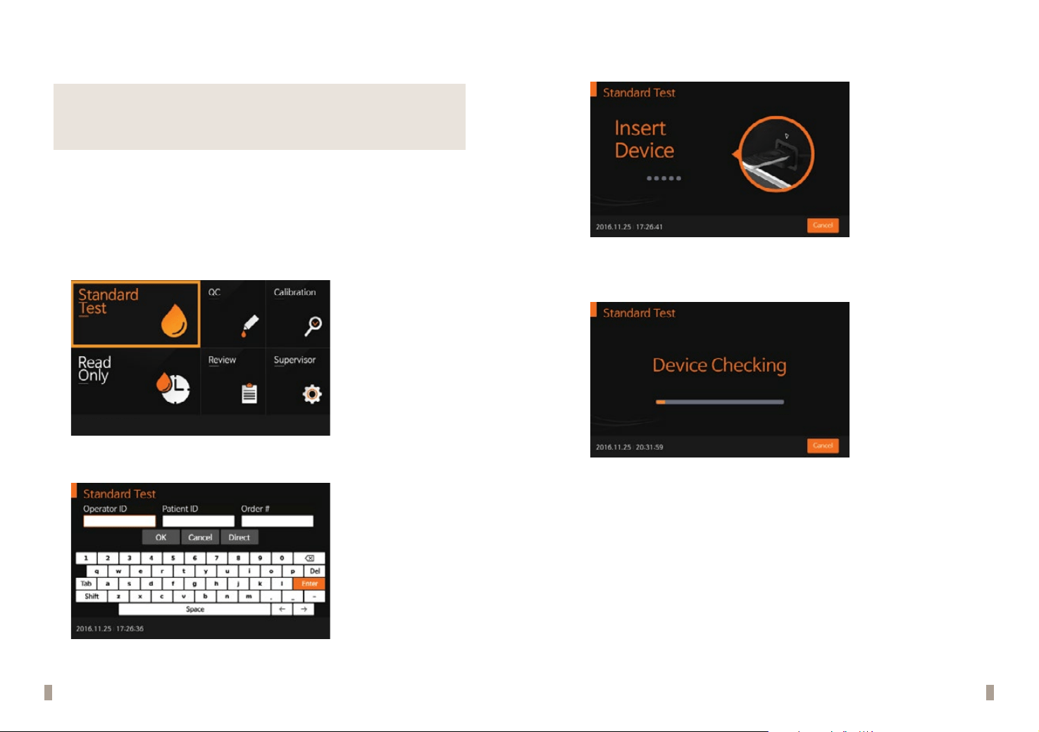
2. Press ‘View Version’ to display the version information for the software and firmware. Press ‘OK’ to
conrm.
S/W Version : V1.00_R003.9(6)
F/W Version : 0.4
Serial NO. : FA20A02AA0027
S/W Version : V1.00_R017.3
F/W Version : 0.5
Serial NO. : FA20A04AA0515
3. Press ‘View Network’ to display the information about the network. Press ‘OK’ to conrm.
192.168.33.100
192.168.33.1
5005
34 35
Performing a Measurement
Check the following before performing a measurement:
· Is the analyzer connected to the AC/DC adapter?
· Are the date and time correct?
· Has the analyzer settings been checked?
Select the desired test mode
The Standard Test mode may be the most convenient for reading a single patient sample, as the user can
perform a Standard Test during the analysis period. The Read Only mode may be the most convenient for
extensive volume testing as the analyzer can quickly read multiple patient samples sequentially.
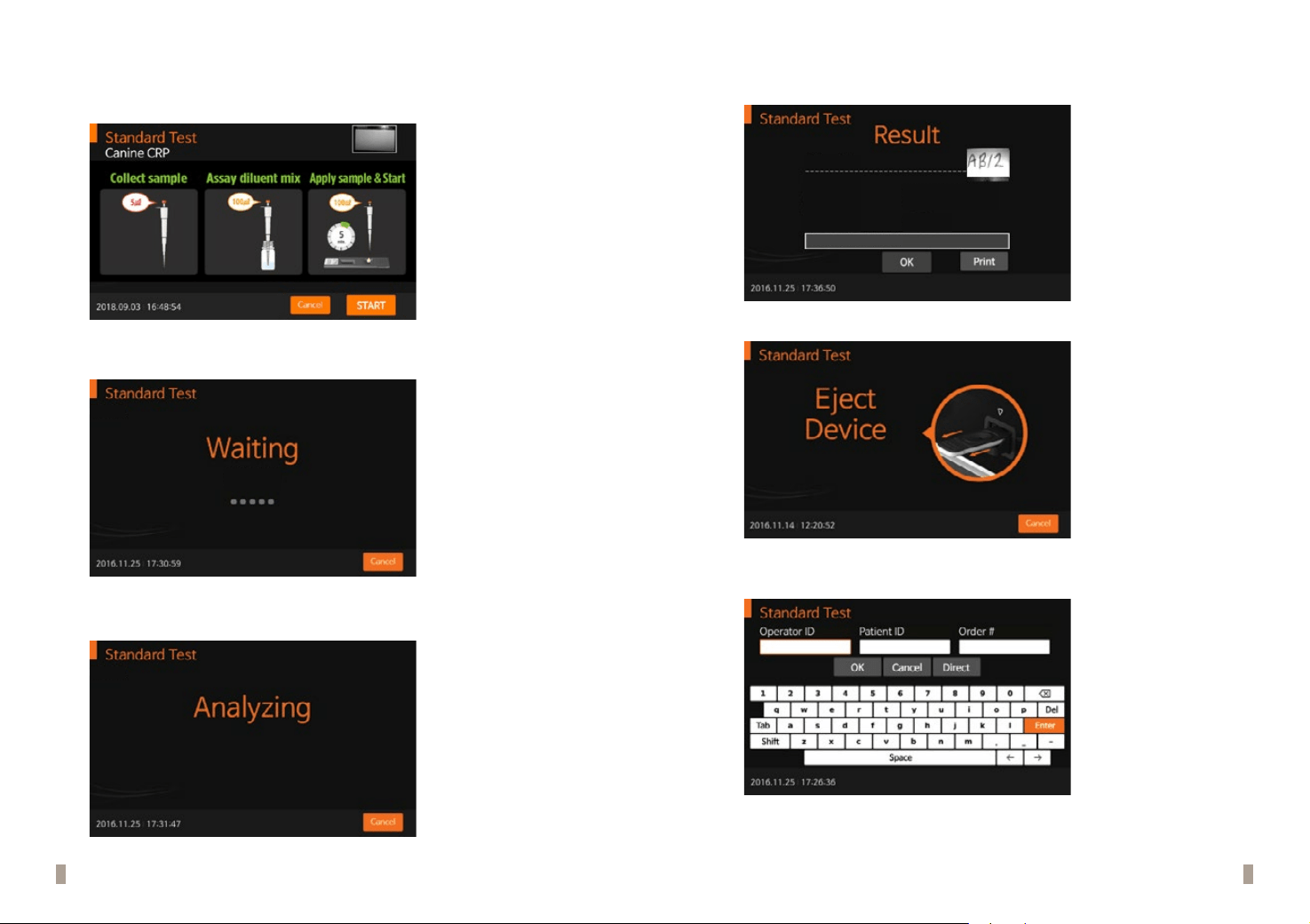
Standard Test mode
1. Select the 'Standard Test' mode. Refer to the assay-specic package insert when collecting specimens for
the test and preparing the test procedure.
2016. 11. 25 l 17:26:26
2. Enter the operator's ID, patient ID, and the order #. The operator's ID can also be entered with the barcode
scanner. If the ID is not entered into the analyzer, the analyzer will regard the operator as a guest user.
3. Once ‘Insert Device’ is displayed on the screen, insert the specied test device into the analyzer’s test slot.
The analyzer automatically reads the information for the test device.
4. Once the test device is inserted into the analyzer, the analyzer will automatically check whether the
device has been used or not. The analyzer also reads the barcode data and conrms the test device is valid
before starting the test.
Canine CRP
36 37
5. After device checking, apply the specimen to the sample well and immediately press ‘START’. If ‘START’ is
not pressed within 20 seconds after applying the specimen, the analyzer will display an error message
indicating that the test cannot be performed.
6. The analyzer will automatically recognize the test device. The time required for analysis depends on type
of test device.
Canine CRP
04:58
7. The analyzer will automatically scan the test device and analyze the test results. The scanning time can
vary with the type of test device.
Canine CRP
8. Once the analysis is nished, the test results will be displayed. The analyzer will print the test results if
auto-printing is enabled.
[ Canine CRP ]
Patient ID:
Date:
Operator ID:
Order #:
Canine CRP:
15.8 ㎎/L
2016/11/25 17:36:47
guest
Procedural Control: Valid
9. Press 'OK' to display the 'Eject Device' screen. The test device can then be removed from the analyzer.
10. Once the test device is ejected, the analyzer will move to another test log-in menu for the next test. Press
'Cancel' to stop the test progress at any time.
38 39
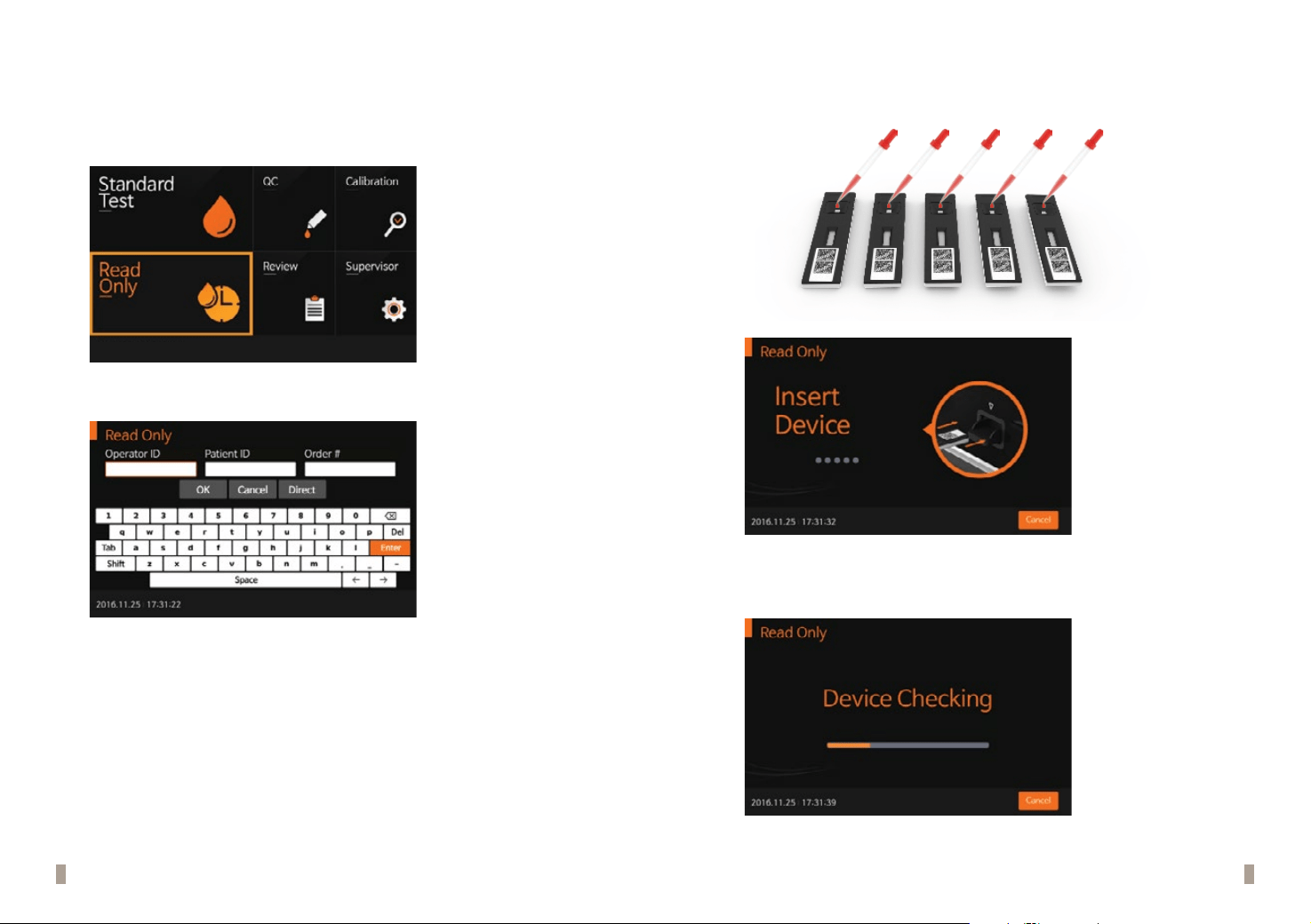
Read Only mode
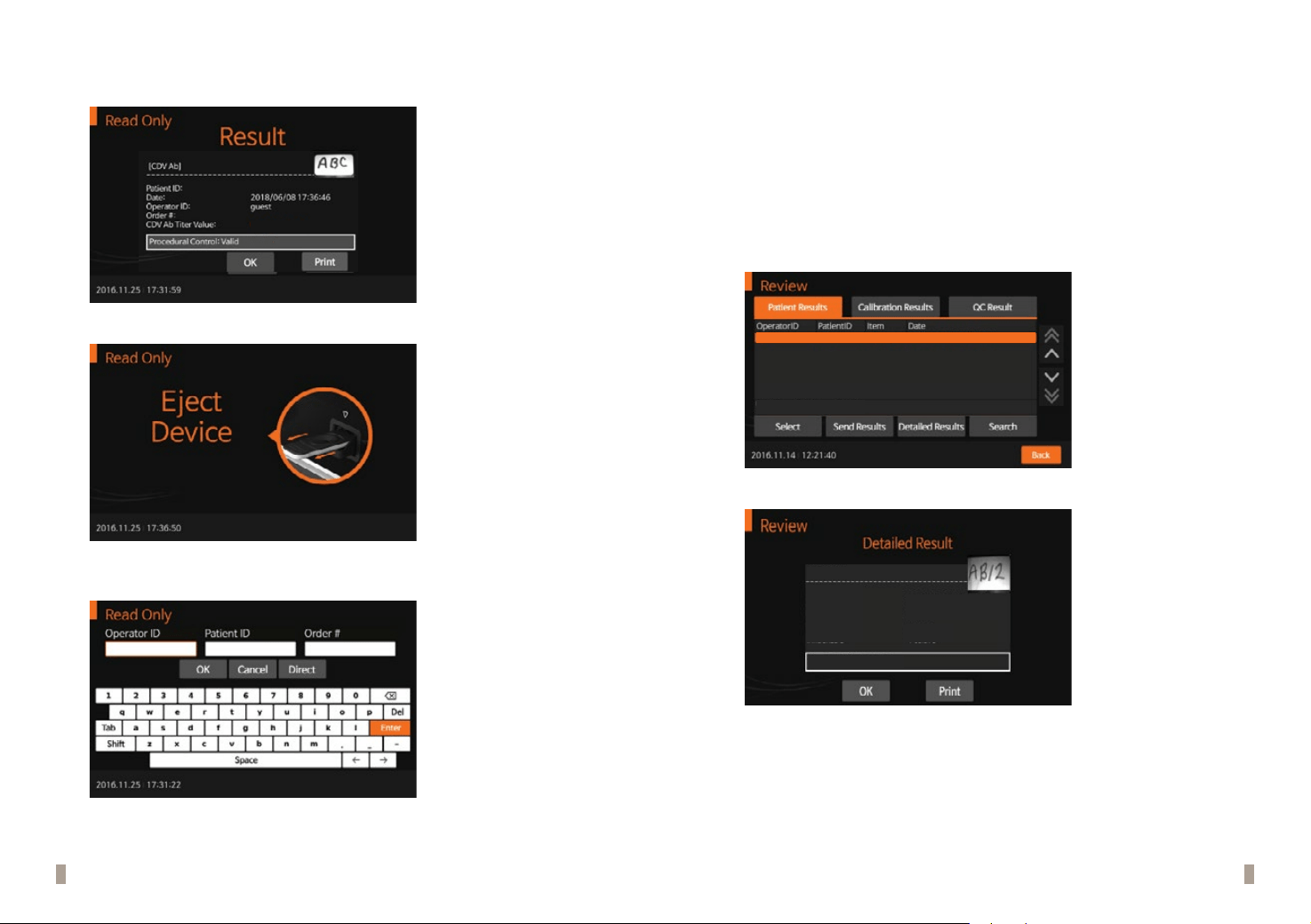
1. Select 'Read Only'. Refer to the assay-specic package insert when collecting the specimen for the test
and preparing the test procedure. [Read only] mode is available only for "Vcheck RDT" products and is not
available for the quantitative tests.
* Please check if 'Read only' mode is available by referring to the item's insert.
2016. 11. 25 l 17:31:12
2. Enter operator's ID, patient ID, and order #. The operator's ID can also be entered with the barcode
scanner. If the ID is not entered into the analyzer, the analyzer will regard the operator as a guest user.
3. Prepare the test device and label it accordingly.
· Add prepared specimen #1 to test device #1, then immediately set the timer to the designated
processing time, as indicated in the assay-specic package insert.
· Add specimen #2 to test device #2 after one minute.
· Continue adding the appropriately prepared specimen to the appropriate test device at an interval of
one minute.
· When the timer goes o for test device #1, insert test device #1 into the analyzer, and the analyzer
will display the result in approximately ten seconds.
4. Once the test device is inserted into the analyzer, the analyzer will automatically check whether the test
device has been used previously or not. The analyzer also reads the barcode data and conrms that the
test device is valid before starting the test.
40 41
5. The analyzer will automatically scan the test device and analyze the test results on the screen within 10
seconds.
[ Canine CRP ]
Canine CRP:
Patient ID:
Date:
Operator ID:
Order #:
Canine CRP:
15.8 ㎎/L
2016/11/25 17:36:47
guest
Procedural Control: Valid
Low titer (1), VN 1:8
6. Press 'OK' to display the 'Eject Device' screen. The test device can then be removed from the analyzer.
7. When the test device is ejected, the analyzer will move to another test log-in menu for the next test.
Press `Cancel' to stop the test progress at any time.
CHAPTER
04. Using the Analyzer Memory and Data Transfer
Displaying Stored Measured Values
1. The BIONOTE V200 analyzer can store 2000 records together with the date, time, and ags, allowing the
records to be reviewed in order from the most recent to the oldest. When the memory is full, the analyzer
will delete the oldest record to add a new result.
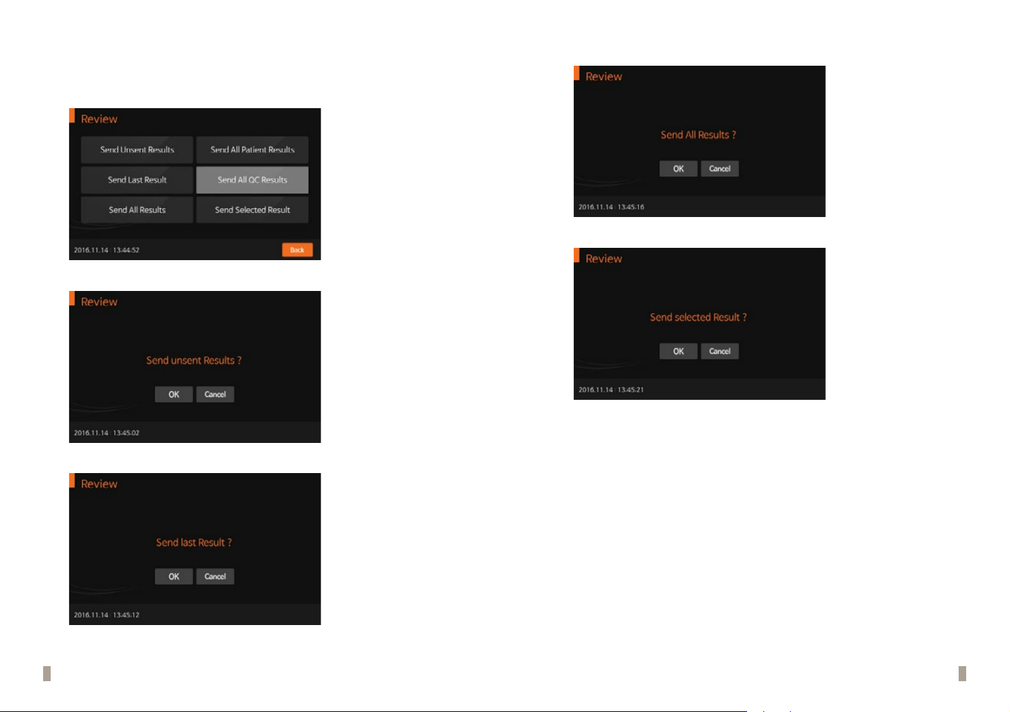
2. The QC details, calibration information, and patient results can be reviewed separately in the review
menu. If you select an entry, you can view the detailed results and send them to a PC or LIS/HIS server
through a LAN connection. You can also delete the records.
cCRP 2016-11-14 12:20:37
guest
Patient ID
guest
Order# Result
3. You may select a test results list. After selecting the desired record, you can view or print it in detail.
[ Canine CRP ]
Canine CRP: 15.8 mg/L
Patient ID:
Date:
Operator ID:
Order #:
Canine CRP:
15.8 ㎎/L
2016/11/25 17:36:47
guest
Procedural Control: Valid
42 43
Send Results
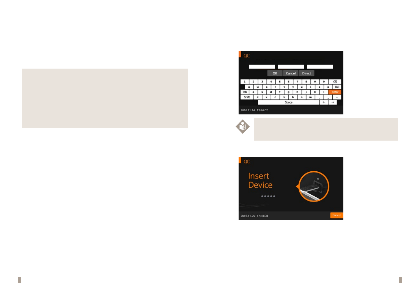
1. With several options available for sending the test results, you can choose the most appropriate method to
communicate with the data server.
<Sending the unsent Results>
<Sending the last Result>
<Sending All Results>
<Sending selected Results>
44 45
CHAPTER 05. Quality Control
Control Test
Control tests can be run if you suspect your system isn’t working correctly or to verify you are performing the
test correctly.
When to use the control
· Whenever your results are not in accordance with your expectations.
· If you have repeated a test, and the result is still lower or higher than expected.
· When you want to check the performance of the analyzer and test device.
· If you drop the analyzer.
Before using the control
· Check the expiration date on the control solution container. Do not use after the expiration date.
How to Perform Quality Control
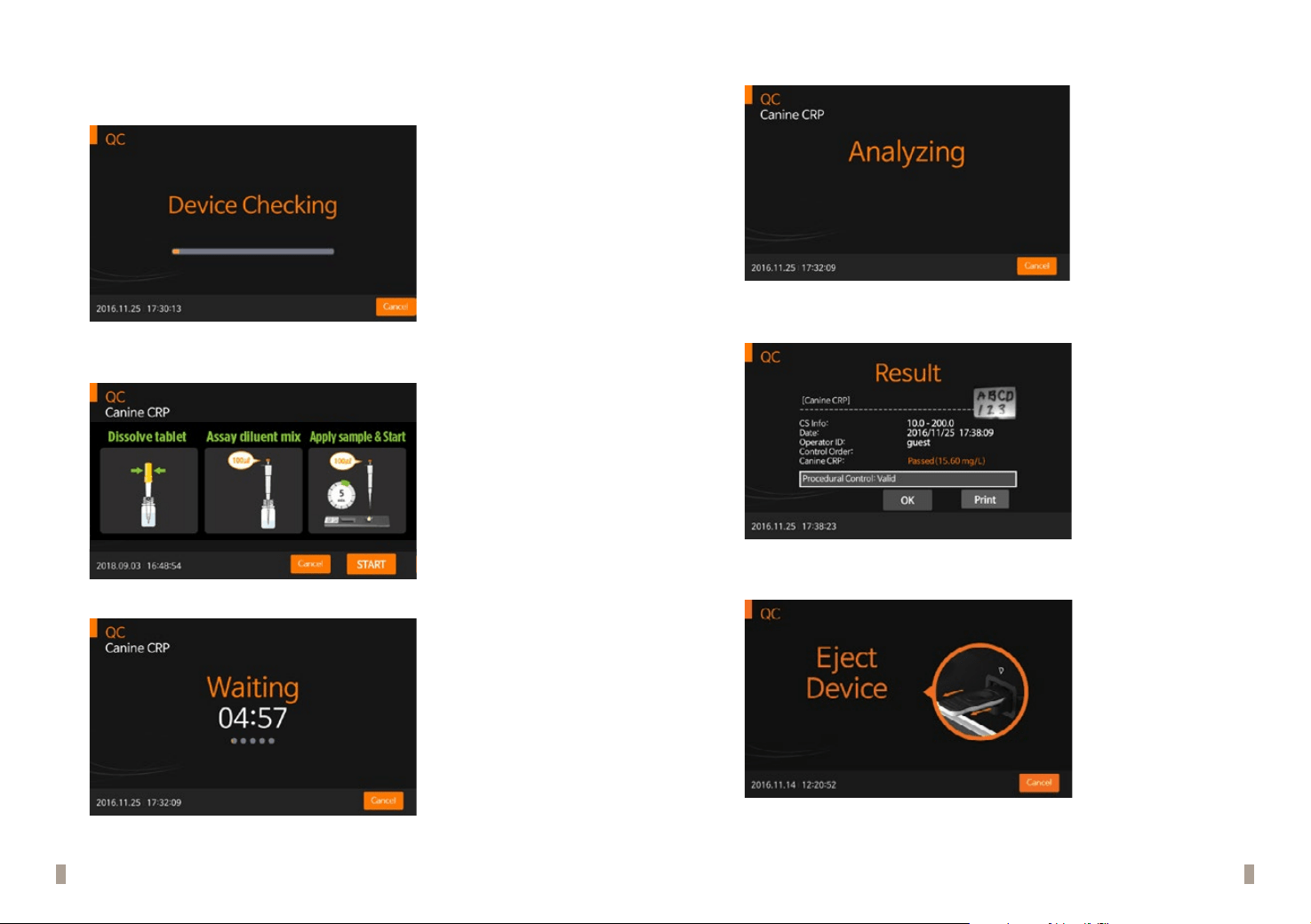
1. To perform quality control according to the specic test type, refer to the assay-specic package insert when
preparing the test with the appropriate QC control solution for each type of test device. Enter the operator ID
and CS Info before starting.
Operator ID Control ID Control Order
Note
The operator ID and CS Info can be entered into the analyzer with the touch panel or a USB
keyboard. This information can also be entered with a BN barcode reader, which is sold separately.
2.
Once ‘Insert Device' is displayed on the screen, insert the test device into the test slot.
46 47
3. Once the test device is inserted into the analyzer, the analyzer will automatically check whether the device
has been used or not. The analyzer will also read the barcode data and conrm that the test device is valid
before starting the test.
4. When the procedure for checking the test device is completed, apply the control solution to the sample
well of the test device and press 'START' immediately.
5. The Waiting screen will be displayed once the test device is being processed in the analyzer.
6. The analyzer will automatically scan and analyze the test results.
7. Once the analysis is nished, the test results will be displayed. The analyzer will print the test results if auto-
printing is enabled.
8. 'Eject Device' will be displayed after the test device analysis is complete. The test device can then be removed
from the analyzer.
48 49
CHAPTER 06. Calibration
Calibration Set Test
The calibration set test is a required function that ensures optimal performance by checking the designated
method.
When to the calibration set
· Whenever the analyzer is powered on
· When you drop the analyzer
· Whenever you do not agree with the results
· When you want to check the performance of an analyzer and the test device
Precautions and warnings
· The calibration set test cannot be replaced with the control test
How to Use the Calibration Set Test
1
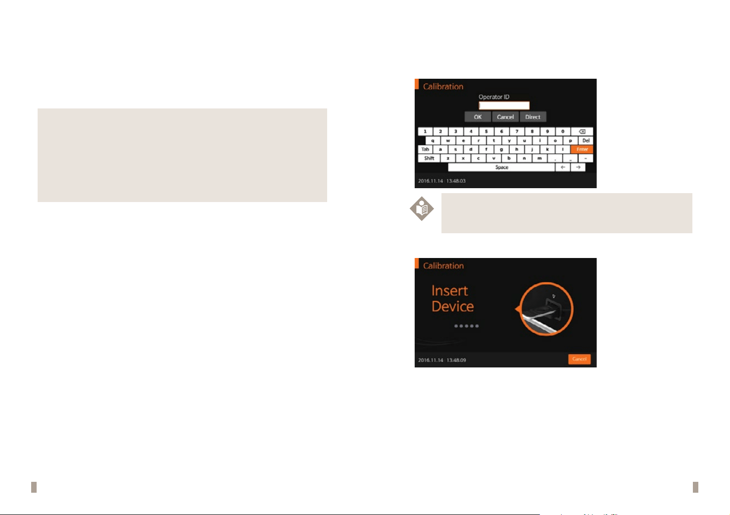
. To run the calibration set test, select ‘Calibration’. Enter the operator's ID before starting the calibration
set test.
Note
The operator's ID can be entered into the analyzer with the touch panel or a USB keyboard. The ID
can also be entered with a BN barcode reader, which is sold separately.
2. Once 'Insert Device' is displayed on the screen, insert CAL-1 into the test slot.
Insert Cal-1
50 51
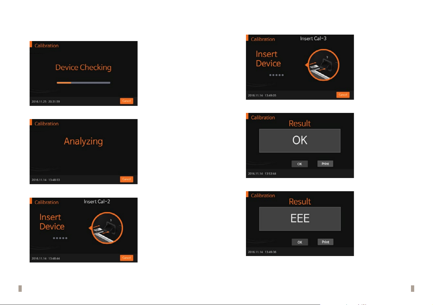
3. Once the device is inserted into the analyzer, the analyzer will automatically check whether CAL-1 has been
used or not. Additionally, the analyzer will read the barcode data and conrm the device validity before
starting the calibration set test.
Calibration
4. The analyzer will automatically scan and analyze CAL-1. This will take approximately 15 seconds.
Calibration
5. Insert CAL-2 for UV testing.
6.
Insert CAL-3 for RGB-LED testing. Ensure that CAL-2 and CAL-3 are inserted in order. Do not change the
order.
7.
If the measured value is within the normal range, ‘OK’ will be displayed on the screen.
8. If the measured value is not within the normal range, ‘EEE’ will be displayed on the screen.
52 53
CHAPTER 07. Cleaning and Maintenance
Cleaning the Analyzer
To prevent analyzer malfunction, keep the test slot free from blood, moisture, or dust. Use a lint-free cloth.
Suitable cleaning solutions are mild suds, 70 % ethanol, or isopropyl alcohol. For professional use (e.g.surgery),
a mixture of 1-propanol, 2-propanol, and glutaraldehyde is recommended.
Caution
Do not use an abrasive cloth or antiseptic solution, as these may damage the display
screen. Always switch o the analyzer before cleaning!
Maintenance and Transportation
Each time the analyzer is turned on, it will automatically perform a self-test and will let you know if
something is wrong.
Note
· Keep the test slot and internal part of the analyzer free from dust.
· The carrying case was designed to store a variety of supplies and to protect your
analyzer.
· For transportation, the analyzer should be stored at -20 to 50°C (-4 to122°F) and
10% to 93% RH.
CHAPTER 08. Screen Messages and Troubleshooting
Warning Messages
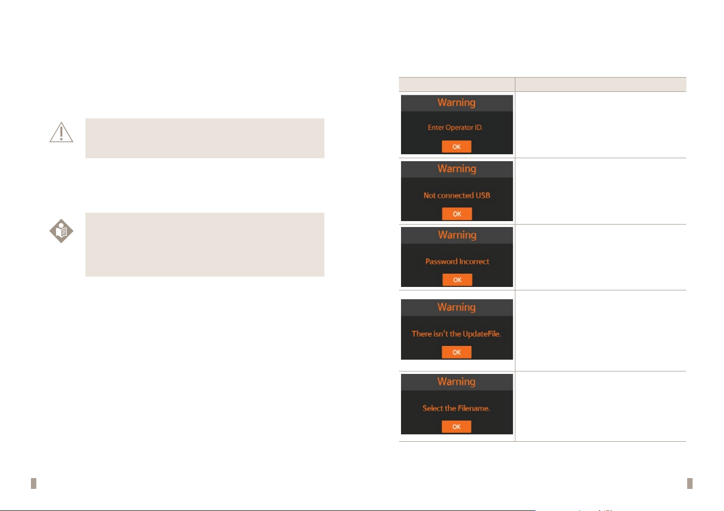
Indication Warning description
Warning: Operator ID.
Pressed `OK' without entering the Operator ID.
Solution
Enter the operator's ID rst, then press ‘OK’.
Warning: USB not connected
USB device is not connected.
Solution
Conrm USB device is connected correctly.
Warning: Password
Entered an incorrect supervisor password.
Solution
Enter a valid password.
Warning: Update File Not Found.
The update le does not exist on the USB device.
Solution
Conrm that the update le is on the USB device.
After ensuring the update le is on the USB drive, connect the
drive and press `OK'.
Warning: Select Filename.
The settings le is not selected in the `Load Settings' menu.
Solution
Check the le name and select the correct le.
54 55
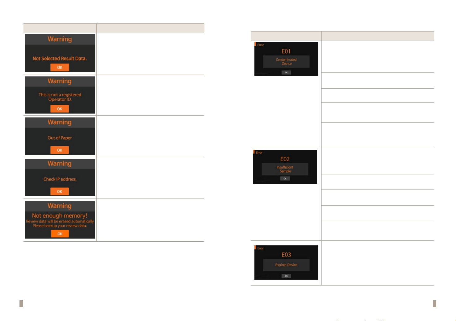
Indication Warning description
Warning: Result data not selected
No selection in the result data list.
Solution
Press ‘Send Selected Result’ after selecting the result.
Warning: Unregistered Operator ID
Entered operator ID is not registered.
Solution
Add operator ID in set mode.
Warning: Out of Paper
There is no printer paper in the analyzer.
Solution
Rell the printer paper.
Warning: Incorrect IP address
Check the IP address.
Solution
Conrm the entered IP address.
Warning: Full memory
The maximum of 2000 records has been stored.
Solution
If the next test result is saved after this warning, the oldest
result has already been erased.
Error Messages
Indication Error description
E01: Contaminated Device
Cause 1: Start button is not pressed immediately after applying the
sample. (sample already started migrating before reading).
Solution: Try with a new device and press the start button immediately
after applying the sample on the device.
Cause 2: Used test kit
Solution: Try with new device.
Cause 3: Too much volume of sample may contaminate the device.
Solution: Try with new device and be careful with sample volume.
Cause 4: Defective device (unlikely)
; Device itself is contaminated. (Scratch/ Damage)
Solution: Try with a new device with a dierent lot number.
Cause 5: Defective machine
; If none of the above causes are found, it could be due to an analyzer
defect.
Solution: Report to BIONOTE with the error message.
E02: Insucient Sample
Cause 1: Too much foam while mixing the tablet.
Solution: Try with a new device and be careful with the foam during
sample preparation.
Cause 2: Small volume of sample is applied.
Solution: Double-check pipette sample volume.
Cause 3: Sticky sample
Solution: Centrifuge the specimen and use only the supernatant.
Cause 4: Too hot and dry temperature
Solution: Try again at room temperature(15-30
o
C) or turn o the heater.
Cause 5: Defective device interrupt proper migration.
Solution: Check if migration is done and report to BIONOTE with the error
message.
E03: Expired Test Device
Cause 1: Expired Device
Solution: Check if the analyzer Date/Time is not properly set.
* Setting> General Setting > Date/Tine
56 57
Indication Error description
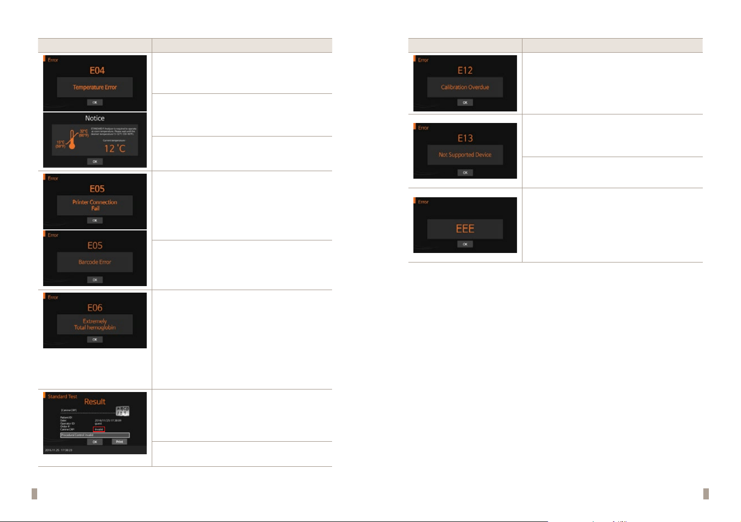
E04: Temperature Error
Cause 1: Device temperature is not between 15~30°C.
Solution: Try with a new device after incubating at room temperature.
Cause 2: Analyzer temperature is not between 15~30°C.
Solution: Try turning on Analyzer after incubating at room temperature.
Cause 3: Defective temperature sensor
Solution: Try after incubation and report to BIONOTE with the error
message.
E05: Communication Error
Cause 1: Communication between the analyzer and barcode reader or
printer has failed.
Solution: Reconnect the analyzer and the external device. If the error
continues after turning the analyzer ON/OFF, report to BIONOTE with the
error message.
Cause 2: Damaged barcode.
Solution: Check if there is a damage on the barcode.
E06: Extremely Total Hemoglobin
Cause 1: Sample is hemolyzed much
(The measured total hemoglobin is not in the range of 7 to 23g/dL.)
Solution:
1. This error occurs with specimens known to have total hemoglobin in
the abnormal range.
2. Specimen with high hemolysis can not be used. Prepare the
specimen again.
3. If the test kit allows whole-blood sample, this error will not be
reported.
Result: Invalid
Cause 1 :
The test is invalid.
Solution:
Retest with a new test device and a new specimen. If the error
continues after turning the analyzer ON/OFF, report to BIONOTE with the
error message.
Cause 2: C-line is out of range.
Solution: Double-check if tablet melting process is completed.
Indication Error description
E12: Calibration Overdue
Cause 1: The calibration is overdue.
Solution: Calibrate analyzer or set up calibration period longer.
* Setting> general setting > Set Calibration and QC
If the error continues after turning the analyzer ON/OFF, report to
BIONOTE with the error message.
E13: Unsupported Test Device
Cause 1: Loaded test device is not appropriate for the analyzer.
Solution: Check the type of test device and conrm it is manufactured
by
BIONOTE
Cause 2: Invalid software
Solution: Update software.
EEE: Internal Error Message for the Analyzer
Cause 1: An internal error has occurred.
Solution: If the error continues after turning the analyzer ON/OFF, report
to BIONOTE with the error message.
58 59
CHAPTER 09. On-Line Update Conguration
Wireless LAN Connection Settings
1
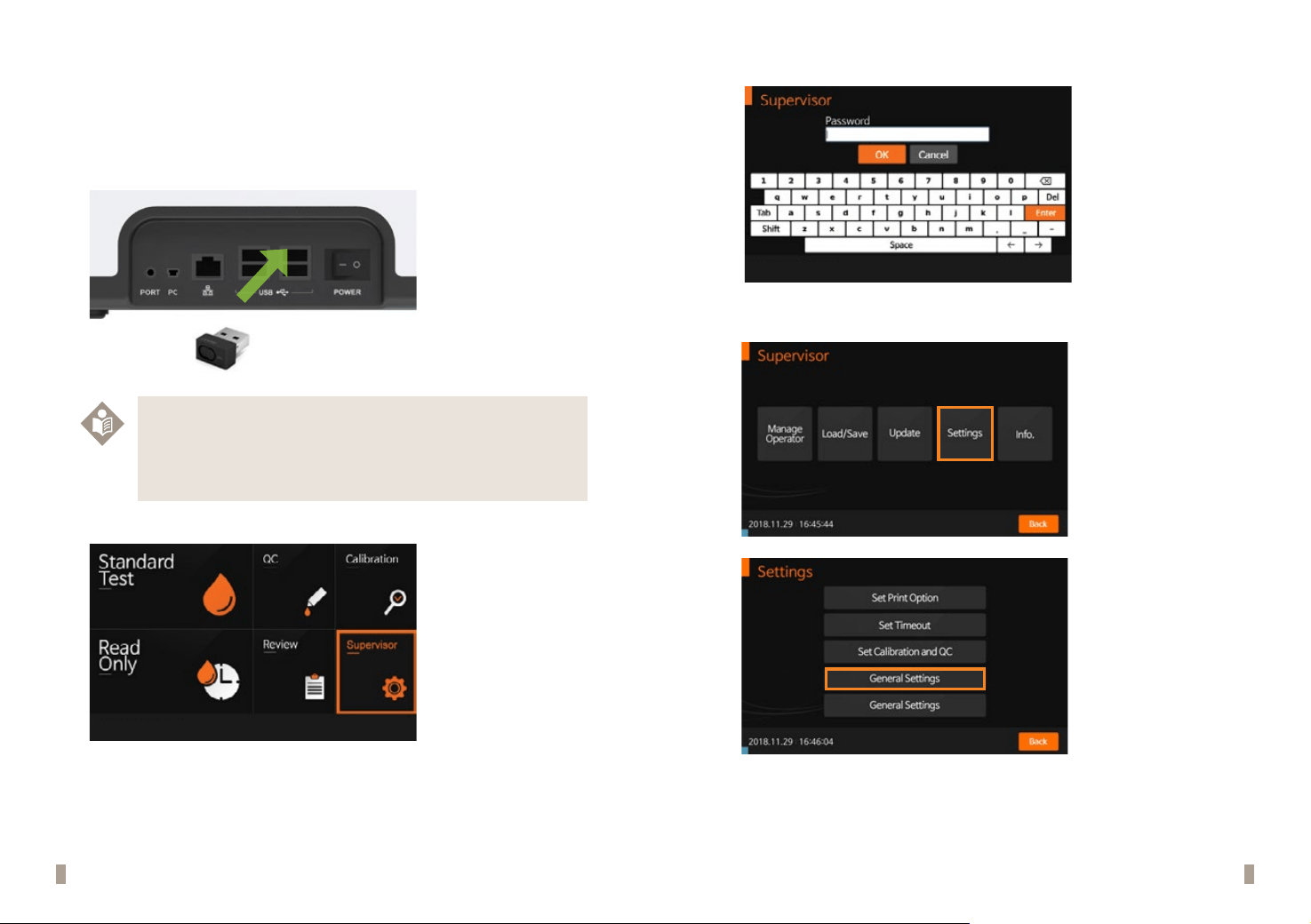
. Insert the wireless LAN card into the USB PORT located in the lower left corner of the device.
Note
Usable Wireless Lan Card Types
· ipTime N100mini
· netis WF2120
· Bless ZIO 1570NU
2. In the main menu, press ‘Supervisor’ to congure the setup mode.
2016. 10. 26 l 16:18:57
3. Input the password and press 'OK' (The initial supervisor password is 0000).
2016. 10. 26 l 16:19:00
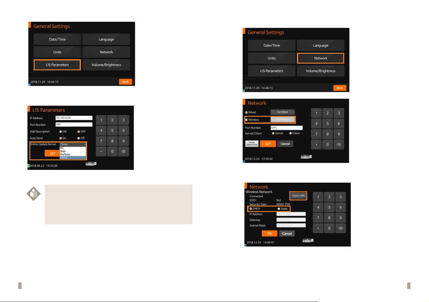
4. In the Supervisor menu, press
①
Settings >
②
General Setting >
③
LIS Parameters.
①
②
60 61
③
5. In the LIS Parameters menu, select a server from the ‘Online Update Server’ list to perform the online update.
Note
Online Update Server List
· PC : Update Server access via PC
· Web : Update Server access via Wireless LAN
· Bionote : Update Server access via Bionote computer network (Not available)
· China : Update Server access via wireless LAN (China only)
6. Return to the General Settings menu and press
①
Network >
②
Set Wireless.
①
②
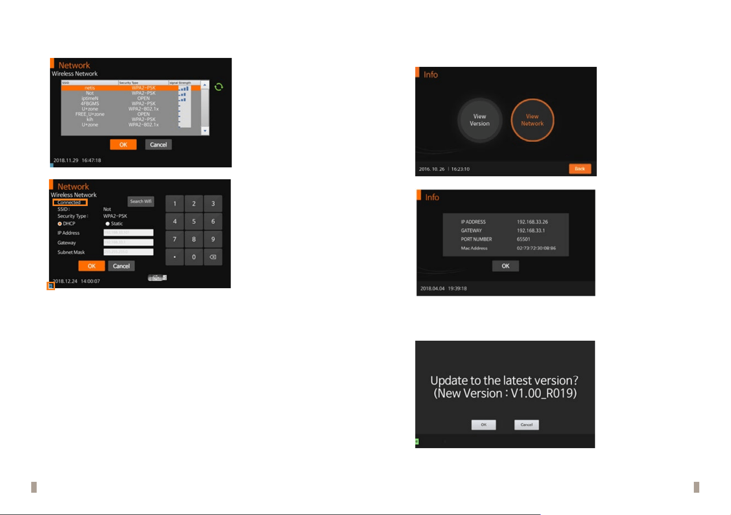
7. Press 'Search WiFi’ to nd the WiFi network you want to use. To setup IP, select your preference between
DHCP (automatically designated) and Static (manual specied).
62 63
8. Select the desired WiFi network from the ‘Wireless Network’ to connect. If a successful connection is made,
'Connected' will be displayed on the top-left corner, and a ‘W’ mark will appear in the lower-left corner.
< Wireless LAN Connection Verication>
1. In the Supervisor menu, press Info. > View Network to conrm the displayed IP address.
2. If the SW of the server is higher than the SW of the device, the message below will be printed when turning
the device back on.

64 65
ANNEX 01. Information for Healthcare Professionals
Protection against Infections
There is a potential risk of infection. Healthcare professionals using the BIONOTE V200 analyzer to perform the
test must be aware that any object coming into contact with a patient sample is a potential infection source.
• Wear protective equipment.
• Apply samples outside the analyzer.
• Follow all other locally applicable guidelines and regulations on health and safety.
ANNEX 02. Reference
1. American Diabetes Association, Clinical Practice Recommendation Guidelines 2003, Diabetes care, Vol.
26. Supplement 1. p.22
2. Stedman, TL. Stedman’s Medical Dictionary, 27th Edition, 1999, p. 2082.
3. Ellen T. Chen, James H. Nichols, Show-Hong Duh, Glen Hortin, MD: Diabetes Technology & Therapeutics,
Performance Evaluation of Blood Glucose Monitoring Devices, Oct 2003, Vol. 5, No. 5: 749 -768.
Warranty
You are a valued customer of BioNote, Inc. It is important to us that you are completely
satised with the BIONOTE V200 analyzer. BioNote, Inc. guarantees the analyzer to be free
from defects and warranty for two years from the original purchase date. If the analyzer
does not work properly during this period because of a defect in materials, BioNote, Inc.
agrees to replace or repair, free of charge, any and all parts proven to be defective and
subject to warranty. This warranty is in lieu of all other warranties, expressed or implied,
including any implied warranty of merchantability of tness for any purpose other than
stated herein. This warranty does not apply to the performance of an analyzer that has
been damaged by accident or has been altered, misused, tampered with, or abused in
any way. This warranty only applies to the original purchaser of the analyzer and/or its
agents.
Return
You must contact BioNote, Inc. before returning your analyzer and will be instructed with specications on the
return procedures. Analyzers returned without authorization will not be accepted.
Disposal
The BIONOTE V200 analyzer must be disposed of according to the local regulations concerning electrical and
electronic equipment disposal. The Waste Electrical and Electronic Equipment (WEEE) regulation implements
the provisions of the European Parliament and Council Directive 2002/96/EC to reduce the amount of EEE
waste for nal disposal. Please contact our representatives in your area for the respective instructions before
disposal.

67
66
MEMO MEMO
V200