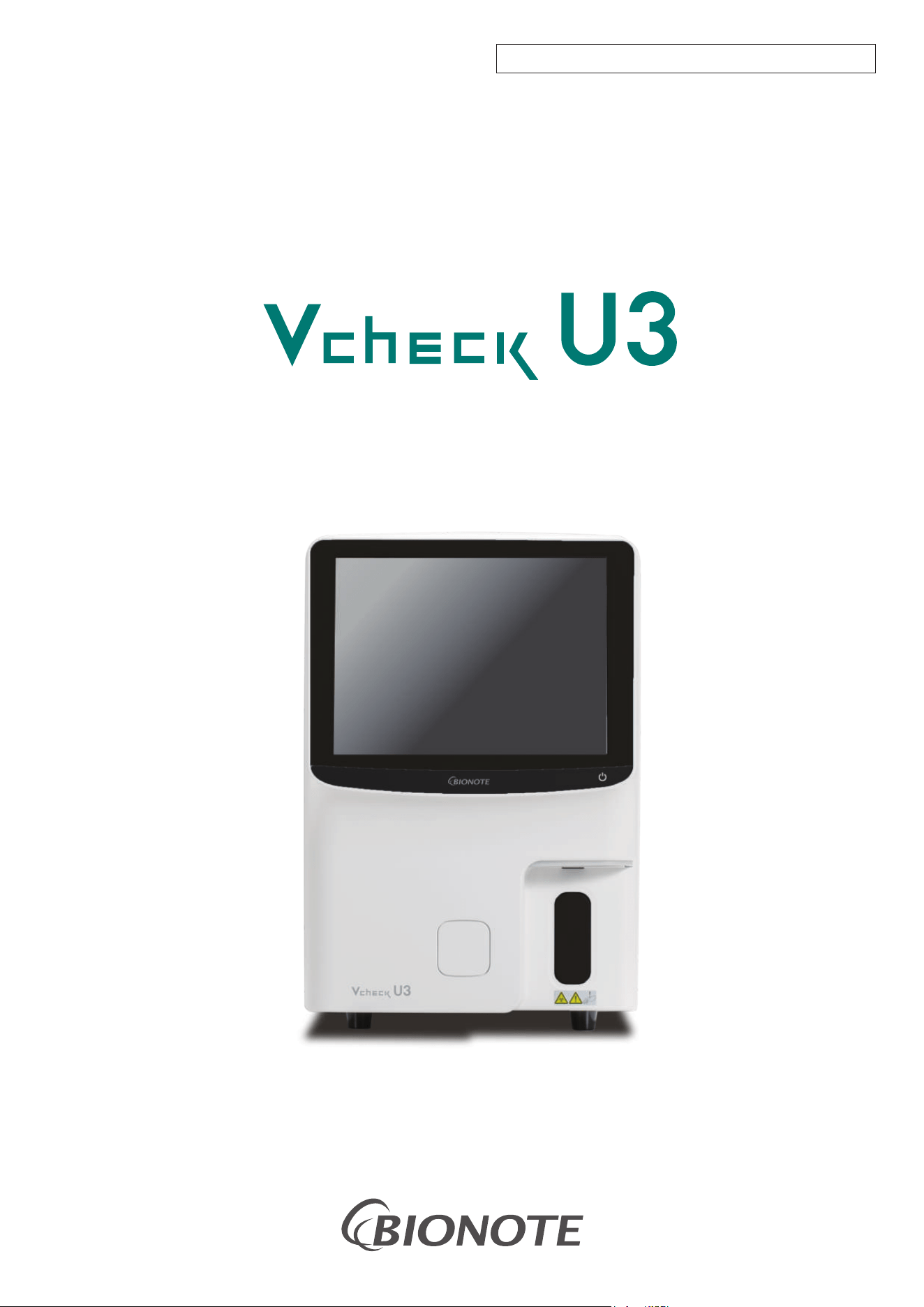
Vcheck U3 is a non-invasive, cost-effective diagnostic tool that provides valuable
information about the urinary tract, renal function, and systemic health. It is
commonly used in small animal and livestock practice and involves the physical,
chemical, and microscopic examination of urine.
- USER MANUAL -
FOR VETERINARY USE ONLY. NOT FOR HUMAN USE.

I
NOTE:
1) Carefully read this manual before operating the analyzer for the first time.
2) Inspect the electrical requirements of the analyzer before power on and properly
connect the grounding wire.
3) Turn off the power and pull out the power plug if the analyzer is idle for a long time.
4) Do not run the analyzer if it’s in an abnormal or damaged condition.
5) There is potential biohazard of the reagents and samples; The operator should
follow proper biosafety practices. Dispose of waste reagent and sample in
accordance with local, national regulations.

II
Disclaimer
This analyzer can only be used for the routine test of animal urine samples.
BIONOTE Inc. is fully responsible for the revision and explanation of the manual and reserves
the right to renovate the relevant contents without separate notification. Some of the
demonstration pictures are for reference and subject to real object if any differences.
All the information included is protected by copyright. No part of this document may be
reproduced, stored or transmitted in any form or by any means unless written authorization by
BIONOTE Inc (hereinafter BIONOTE).
The manual defines the rights and obligations between BIONOTE and the customers about
responsibility for quality warranty and after-sale service, also the related agreements on
commencement and termination.
BIONOTE warrants the analyzer sold by the BIONOTE and its authorized agents to be free from
defects in workmanship and materials during normal use by the original purchaser. This warranty
shall continue for a period of one year after the date of installation. The analyzer life is ten years.
All instructions must be followed strictly in operation. BIONOTE assumes no liability in the
following situations even during the period of warranty:
◆ Failure due to abuse the analyzer or neglect the maintenance.
◆ Use reagents and accessories other than manufactured or recommended by BIONOTE.
◆ Failure due to operation not under the instructions described in the manual.
◆ Replace accessories not specified by BIONOTE, or after maintenance or repair by a service
agent not approved or authorized by BIONOTE.
CAUTION
BIONOTE does not make any implied warranties of marketability or applicability for a particular
purpose.

III
VC8001EA
* Product name: AI-Libre Urinalysis System
* Model name: Vcheck U3
* FCC ID: 2BQN5VC8001
Doc. No.: I8001-3E
Issued date: 2026-08-25

IV
Content
Chapter 1 Manual Overview .................................................................................................................. 1
1.1 Overview ........................................................................................................................................... 1
1.2 Scope of application of the manual .................................................................................................. 1
1.3 Manual conventions ...................................................................................................................... 1
1.3.1 Use restrictions ................................................................................................................................. 1
1.3.2 Installation restrictions ...................................................................................................................... 2
1.3.3 Personal protection and infection control ......................................................................................... 3
1.4 Symbol ............................................................................................................................................ 4
1.4.1 Symbols used in this manual ........................................................................................................... 4
1.4.2 Symbols used on the analyzer or packaging ................................................................................. 4
Chapter 2 Safety Information .................................................................................................................. 8
2.1 Overview .......................................................................................................................................... 8
2.2 Safety information of analyzer symbol ............................................................................................. 8
2.2.1 Front of the analyzer ........................................................................................................................ 8
2.2.2 Back of the analyzer ......................................................................................................................... 9
2.3 Computer virus protection .............................................................................................................. 10
2.4 Installation, maintenance, repair and operation ............................................................................. 10
2.5 Reagents, quality control, waste liquid, waste materials and other waste disposal ...................... 11
Chapter 3 System Overview ................................................................................................................. 13
3.1 Range of application....................................................................................................................... 13
3.2 Test results ..................................................................................................................................... 13
3.2.1 Chemical test results ..................................................................................................................... 13
3.2.2 Sediment test results ..................................................................................................................... 13
3.2.3 RBC morphology test item ............................................................................................................. 14
3.2.4 Urine physical test item ................................................................................................................. 14
3.3 Analyzer Composition .................................................................................................................... 15
3.3.1 Touch type colorful LCD display screen......................................................................................... 16
3.3.2 Touch power button........................................................................................................................ 16
3.3.3 Status indicator ............................................................................................................................... 16
3.3.4 Sample probe ................................................................................................................................. 17

V
3.3.5 The test sampling button ................................................................................................................ 17
3.3.6 Chemistry test door ........................................................................................................................ 17
3.3.7 Power switch .................................................................................................................................. 18
3.3.8 Power interface (with guard filter) ........................................................................................... 19
3.3.9 Input/output interface...................................................................................................................... 19
3.3.10 SENSOR ........................................................................................................................................ 20
3.3.11 WASTE ........................................................................................................................................... 20
3.3.12 Speaker .......................................................................................................................................... 20
3.3.13 Microscope shooting system .......................................................................................................... 21
3.3.14 Reagent pumping components ...................................................................................................... 21
3.3.15 Waste liquid pumping component .................................................................................................. 21
3.3.16 Industrial control board ................................................................................................................... 22
3.3.17 Fluid system control board ............................................................................................................. 22
3.3.18 Syringe assembly ........................................................................................................................... 22
3.3.19 Chemistry test device ..................................................................................................................... 22
3.4 Reagent .......................................................................................................................................... 23
3.4.1 Detergent 1 ..................................................................................................................................... 24
3.4.2 Detergent 2 ..................................................................................................................................... 24
3.4.3 Control material and calibrator ....................................................................................................... 24
Chapter 4 Analyzer Installation ............................................................................................................. 26
4.1 Overview ........................................................................................................................................ 26
4.2 Unpack and check .......................................................................................................................... 26
4.3 Installation requirement .................................................................................................................. 26
4.3.1 Installation space requirement ....................................................................................................... 26
4.3.2 Power requirements ....................................................................................................................... 27
4.3.3 Working environment requirements ............................................................................................... 28
4.4 Waste liquid pipeline connection .................................................................................................... 28
4.5 Power cord connection ................................................................................................................... 29
4.6 Reagent installation and replacement ............................................................................................ 30
4.6.1 Screw cap and sealing rubber plug disassembly ........................................................................... 30
4.6.2 Software side operation ................................................................................................................. 31

VI
Chapter 5 Analyzer Setting ................................................................................................................... 34
5.1 Overview ........................................................................................................................................ 34
5.2 Normal setting ................................................................................................................................ 34
5.2.1 Normal ............................................................................................................................................ 35
5.2.2 Print setting .................................................................................................................................... 36
5.3 Item settings ................................................................................................................................... 37
5.3.1 Chemistry item settings .................................................................................................................. 37
5.3.2 Urine sediment item settings .......................................................................................................... 38
5.3.3 Physical and chemical parameters settings ................................................................................... 40
5.4 Network settings ............................................................................................................................. 41
5.4.1 Local connection ............................................................................................................................ 41
5.4.2 AMS&LIS connection ..................................................................................................................... 41
5.5 User management .......................................................................................................................... 42
5.6 Dictionary maintenance .................................................................................................................. 43
Chapter 6 Analyzer Operation ............................................................................................................... 44
6.1 Overview ........................................................................................................................................ 44
6.2 Preparation before operation ......................................................................................................... 45
6.3 Precautions .................................................................................................................................... 45
6.4 Check before starting ..................................................................................................................... 46
6.4.1 Check host space ........................................................................................................................... 46
6.4.2 Check waste liquid container ......................................................................................................... 46
6.4.3 Check consumables ....................................................................................................................... 46
6.4.4 Prepare test strips .......................................................................................................................... 46
6.4.5 Check the printer (optional) ............................................................................................................ 46
6.4.6 Check the liquid pipeline and power supply ................................................................................... 46
6.5 Samples collection and handling .................................................................................................... 47
6.6 Power on and user login ................................................................................................................ 48
6.6.1 Power on ........................................................................................................................................ 48
6.6.2 Execution of analysis system self-inspection ................................................................................. 49
6.6.3 Log in to the “Admin” account ........................................................................................................ 49
6.6.4 Standby test interface..................................................................................................................... 50

VII
6.7 Quality control and calibration ........................................................................................................ 50
6.7.1 Quality control ................................................................................................................................ 50
6.7.2 Calibration ...................................................................................................................................... 50
6.8 Software interface .......................................................................................................................... 50
6.8.1 Software test interface.................................................................................................................... 50
6.8.2 Data interface ................................................................................................................................. 51
6.8.3 Quality control interface.................................................................................................................. 52
6.8.4 Menu interface ................................................................................................................................ 52
6.8.4.1 Calibration ...................................................................................................................................... 53
6.8.4.2 Replacing reagents ........................................................................................................................ 53
6.8.4.3 Status ............................................................................................................................................. 54
6.8.4.4 Maintenance ................................................................................................................................... 54
6.8.4.5 Settings .......................................................................................................................................... 55
6.8.4.6 Log.................................................................................................................................................. 55
6.8.4.7 About .............................................................................................................................................. 56
6.9 Sample analysis ............................................................................................................................. 56
6.9.1 Daily test interface .......................................................................................................................... 56
6.9.2 Start testing .................................................................................................................................... 57
6.9.2.1 Urine sediment test ........................................................................................................................ 57
6.9.2.2 Urine chemistry test ........................................................................................................................ 60
6.9.2.3 Urine chemistry + urine sediment test ............................................................................................ 63
6.9.3 Display interface after the test ........................................................................................................ 63
6.9.3.1 Manual classification of sediment analysis .................................................................................... 64
6.9.3.2 Chemistry ....................................................................................................................................... 67
6.9.3.3 Physical Parameters ...................................................................................................................... 67
6.9.3.4 Red blood cell phase ...................................................................................................................... 68
6.10 Shutdown ....................................................................................................................................... 69
6.11 When the analyzer stops working ................................................................................................... 70
Chapter 7 Quality Control ...................................................................................................................... 71
7.1 Overview ........................................................................................................................................ 71
7.2 Quality control interface.................................................................................................................. 71

VIII
7.2.1 Quality control selection and gear information ............................................................................... 71
7.2.2 History quality control information of urine sediment ..................................................................... 72
7.2.3 History quality control display information of chemistry ................................................................. 72
7.2.4 Quality control interface button ...................................................................................................... 73
7.3 Quality control settings ................................................................................................................... 73
7.3.1 Quality control settings and tests of sediment ............................................................................... 73
7.3.1.1 Item selection ................................................................................................................................. 73
7.3.1.2 Data filling and saving .................................................................................................................... 74
7.3.1.3 Quality control tests ........................................................................................................................ 75
7.3.2 Chemistry quality control settings and tests ................................................................................... 76
7.3.2.1 Item selection ................................................................................................................................. 76
7.3.2.2 Data filling and saving .................................................................................................................... 77
7.3.2.3 Quality control tests ........................................................................................................................ 78
7.4 Quality control algorithm ................................................................................................................ 80
7.5 Quality control printing.................................................................................................................... 80
Chapter 8 Analyzer Calibration ............................................................................................................. 81
8.1 Overview ........................................................................................................................................ 81
8.2 Microscope calibration operation ................................................................................................... 82
8.2.1 Microscope calibration.................................................................................................................... 82
8.3 Calibration of calibrator .................................................................................................................. 83
8.4 Calibration history ........................................................................................................................... 87
Chapter 9 Analyzer Maintenance .......................................................................................................... 88
9.1 Overview ........................................................................................................................................ 88
9.2 Maintenance operation interface .................................................................................................... 89
9.3 Rinse .............................................................................................................................................. 89
9.4 Soak ............................................................................................................................................... 90
9.5 Clean Strip Holder .......................................................................................................................... 90
9.6 Empty ............................................................................................................................................. 92
9.7 Priming ........................................................................................................................................... 93
9.8 Auto focusing .................................................................................................................................. 93
9.9 Cleaning and maintenance ............................................................................................................ 95

IX
Chapter 10 Fault Handling ...................................................................................................................... 96
10.1 Overview ........................................................................................................................................ 96
10.2 Approach to fault handling ............................................................................................................. 96
10.3 Seeking technical support .............................................................................................................. 97
10.4 Common faults and handling methods........................................................................................... 97
10.4.1 The host cannot be turned on ........................................................................................................ 98
10.4.2 No display after startup .................................................................................................................. 98
10.4.3 The printer cannot print .................................................................................................................. 98
10.4.4 A warning message displays on the screen: Little or no detergent ................................................ 99
10.4.5 An alarm message displays on the screen: The waste liquid is full ............................................... 99
10.4.6 An alarm message displays on the screen: No reagent is detected .............................................. 99
10.4.7 An alarm message displays on the screen: No card is available or a card reading error .............. 99
10.5 Fault code table ............................................................................................................................ 100
Appendix A Specifications ........................................................................................................................ 103
A1.Outline Specification Size and Weight................................................................................................. 103
A2.Normal working environment ............................................................................................................... 103
A3.Storage and transportation environment ............................................................................................. 103
A4.Electrical specification ......................................................................................................................... 103
A5.Storage capacity .................................................................................................................................. 103
Appendix B: List of Main Replacement Parts ........................................................................................... 104
Appendix C: List of Annexes ..................................................................................................................... 105
Appendix D: Unit Results Comparison Table ............................................................................................ 106
Appendix E: Toxic and Hazardous Substances or Elements ................................................................... 108
Chapter 1 Manual Overview
1
Chapter 1 Manual Overview
1.1 Overview
This article introduces how to use the Vcheck U3 Operation Manual. This manual comes with it,
giving a detailed description of the use, function and operation of the Vcheck U3. Before using the
Vcheck U3, please read and understand the contents carefully to ensure that the Vcheck U3 can be
used correctly, and exert its best performance, and ensure the safety of the operator.
1.2 Scope of application of the manual
This manual is suitable for professionals to read. It’s used to:
◼ Understand the hardware and software of Vcheck U3.
◼ Set system parameters.
◼ Perform daily operations.
◼ Perform system maintenance and fault handling.
1.3 Manual conventions
In this manual, different fonts and formats are used to distinguish the content with special meaning in
the text.
Format
Meaning
[××]
×× is the button on the touch screen or external
keyboard
"××"
×× is the interface display information of Vcheck U3
××
×× is the quoted chapter
All illustrations provided in this manual are only examples, please do not use them for other purposes.
The graphics, settings or data in the illustration may not be the same as the actual display you see on
the Vcheck U3 analyzer.
1.3.1 Use restrictions
(1) The Vcheck U3 is limited to in vitro diagnostic reference analysis of animal urine.
(2) Anyone who uses, moves, installs, and maintains, must read this manual carefully and strictly
follow the requirements of this manual. Otherwise, it may cause accidents and lose the free
warranty opportunity of BIONOTE.
(3) The reagents specified or recommended by BIONOTE have been strictly detected by BIONOTE
and can make this analyzer achieve satisfactory measurement and analysis effects. The use of

Chapter 1 Manual Overview
2
objects that are not specified and recommended by BIONOTE will affect the measurement and
analysis effects of the analyzer. And it may cause accidents and lose the free warranty
opportunity of BIONOTE.
(4) Repairs for any reason should be approved by BIONOTE, and specified parts by BIONOTE
should be used in any replacement of parts. Otherwise, it may cause accidents and lose the free
warranty opportunity of BIONOTE.
(5) Failure to follow the operations in this manual for regular care and maintenance will affect the
measurement and analysis effects of the analyzer, and reduce the service life of the analyzer,
and may cause accidents. Meanwhile, the free warranty opportunity of BIONOTE will be lost.
1.3.2 Installation restrictions
(1) The first installation must be completed by qualified engineers authorized by BIONOTE.
(2) The analyzer must be placed on a level and stable work platform, avoid direct sunlight,
supercooling and overheating air outlets, and keep away from dryers, centrifuges, X-ray
equipment, copiers, and ultrasonic cleaners.
(3) To maintain a good ventilation effect, a certain amount of space must be reserved around the
analyzer. A distance of at least 30cm between the analyzer and surrounding objects must be
reserved to facilitate ventilation. There should be enough space around the analyzer for
maintenance and repair.
(4) Before the initial operation of the analyzer, it should be confirmed whether the fluid system of the
reagent is correct and reliable; whether the external pipeline is bent and obstructs the smooth
flow of liquid, whether the waste liquid is discharged into an appropriate container.
(5) To prevent electrical interference and personal safety of the user, please make sure that the
grounding wire of the analyzer shell is well grounded before use.
Note
⚫ Any unauthorized person or person who is not qualified to repair the analyzer shall
not open the screws on the analyzer shell at any time, otherwise all problems
happened will be borne by the user!

Chapter 1 Manual Overview
3
1.3.3 Personal protection and infection control
(1) The user must abide by the operating requirements of the laboratory or clinical test during
sample testing and daily maintenance and care, and wear medical gloves and safety glasses,
and avoid direct contact between the skin and the measurement sample.
(2) Since all clinical samples are potentially infectious, it is necessary to follow established
laboratory or clinical operating procedures, wear work clothes, medical gloves and safety
glasses when handling these objects. There is no smoking, eating or drinking, and no mouth
blowing or sucking work pipelines in the work area.
(3) Since the waste liquid produced by the sample and the analyzer contains potential pollutants,
which may have biological and chemical hazards, special care should be taken during the
processing, and the relevant laws and regulations of the local government must be followed
when cleaning, processing, and discharging.
(4) The storage of reagents should be stored and kept in accordance with the operating manual. The
user of this analyzer is obliged to establish and maintain effective storage and requisition
measures to prevent the expired use, deterioration, misuse, and ingestion of reagents. The
storage of reagents should avoid extremely cold and heat.
Note
⚫ If the storage temperature is lower than 0℃, the reagent will freeze. The reagent shall
be stopped using once it freezes.
⚫ Reagents should avoid direct sunlight and prevent evaporation and contamination.
Tighten the reagent container lid and minimize the aperture of the reagent lid when
the pipeline passes through the reagent lid to avoid evaporation and contamination.
Chapter 1 Manual Overview
4
1.4 Symbol
1.4.1 Symbols used in this manual
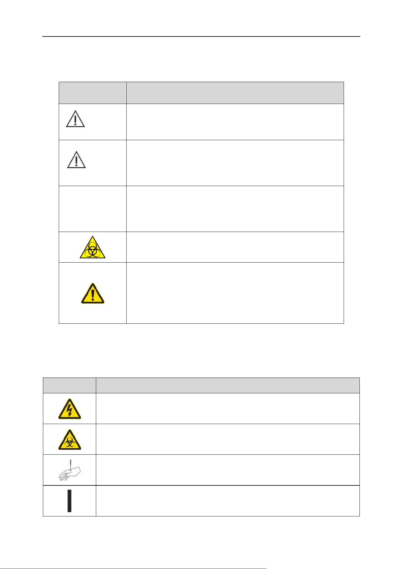
Symbol
Meaning
WARNING
Remind the operator to follow the instructions under the symbol,
otherwise it may cause personal injury.
CAUTION
Remind the operator to follow the instructions under the symbol,
otherwise it may cause product failure, damage, or it may affect
test results.
Note
Remind the operator to follow the instructions under the symbol
and emphasize the important information in the operation steps or
the content that requires special attention from the user.
Remind the operator to follow the instructions under the symbol,
otherwise it may have potential biological infectious hazard.
Warning sign. In all cases where this mark is encountered, the
operator must refer to the attached documents so as to clarify the
nature of the potential hazard and any countermeasures that must
be taken.
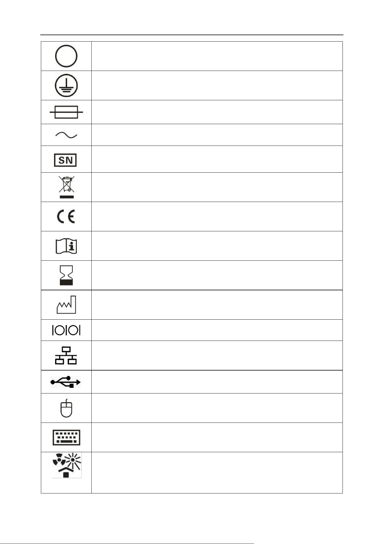
1.4.2 Symbols used on the analyzer or packaging
This analyzer may contain the following symbols:
Symbol
Meaning
Be careful, there is a hazard of electric shock
Biological hazard
Avoid getting your hands stabbed.
Connect (power supply)
Chapter 1 Manual Overview
5
Disconnect (power supply)
Protect grounding
Fuse
Communication
Serial No.
Electrical and electronic product recycling mark
CE mark
Consult instructions for use
Use-by date
Date of manufacture
Serial port
Ethernet interface
USB interface
Mouse interface
Keyboard interface
Protect from heat and radioactive sources
Chapter 1 Manual Overview
6
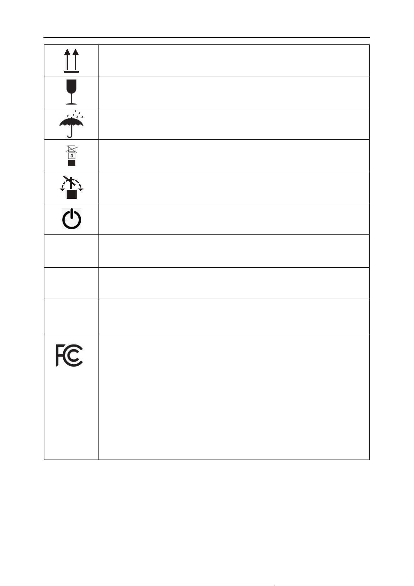
Up
Fragile objects, please be careful to carry
Keep dry
Limit of stacking layers
No tumbling
Standby power control
WASTE
Waste liquid interface
SENSOR
Waste liquid sensor interface
HDMI
HDMI video transmission interface
FCC Symbol
The FCC symbol indicates that this product complies with Part 15 of the FCC Rules.
Operation is subject to the following two conditions:
(1) This device may not cause harmful interference, and
(2) This device must accept any interference received, including interference that may
cause undesired operation.
The FCC mark signifies that the equipment has been tested and found to comply with
the limits for a Class A/B digital device pursuant to Part 15 of the FCC Rules.

Chapter 1 Manual Overview
7
FCC Declaration of Conformity
Note: This equipment has been tested and found to comply with the limits for a Class B digital device,
pursuant to part 15 of the FCC Rules. These limits are designed to provide reasonable protection
against harmful interference in a residential installation. This equipment generates, uses and can
radiate radio frequency energy and, if not installed and used in accordance with the instructions, may
cause harmful interference to radio communications. However, there is no guarantee that
interference will not occur in a particular installation. If this equipment does cause harmful
interference to radio or television reception, which can be determined by turning the equipment off
and on, the user is encouraged to try to correct the interference by one or more of the following
measures:
— Reorient or relocate the receiving antenna.
—Increase the separation between the equipment and receiver.
—Connect the equipment into an outlet on a circuit different from that to which the receiver is
connected.
—Consult the dealer or an experienced radio/TV technician for help.
This device complies with part 15 of the FCC Rules. Operation is subject to the following two
conditions:
(1) This device may not cause harmful interference, and (2) this device must accept any interference
received, including interference that may cause undesired operation.
Any changes or modifications not expressly approved by the party responsible for compliance could
void the user's authority to operate the equipment.
RF Exposure Statement
The device has been evaluated to meet general RF exposure requirement.
8
Chapter 2 Safety Information
2.1 Overview
This chapter mainly describes the safety information used on the analyzer, please strictly follow it to
ensure the safety of personnel and the analyzer.
2.2 Safety information of analyzer symbol
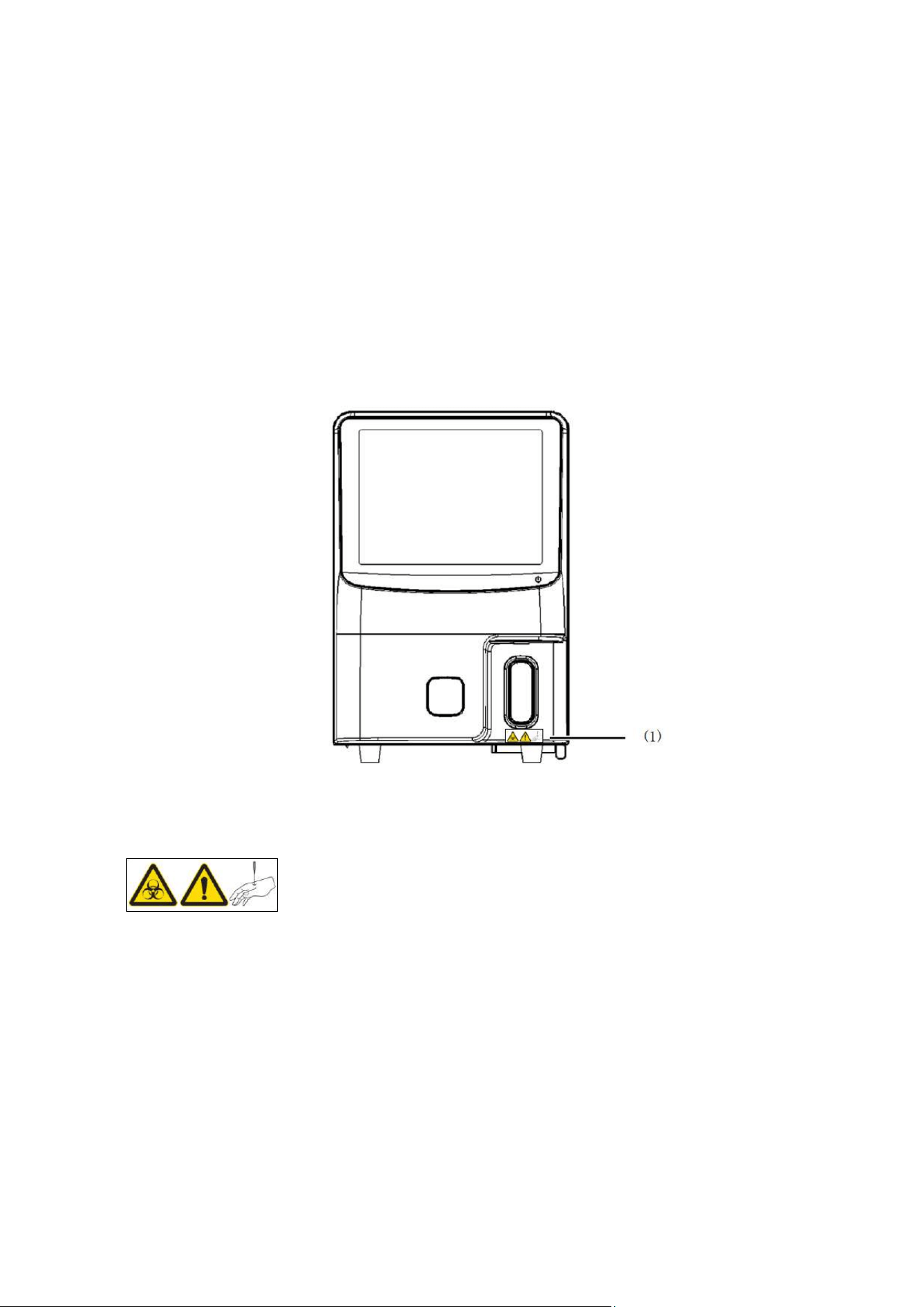
2.2.1 Front of the analyzer
Figure 2-1 Front view of the analyzer
(1)
◼ There may be a risk of infection. In principle, all parts and surfaces of the analyzer should
be considered as a risk of infection.
◼ The sample probe is sharp, so be careful.
◼ The sample probe is a moving part, and the operator is not allowed to touch it without
training.
Chapter 2 Safety Information
9
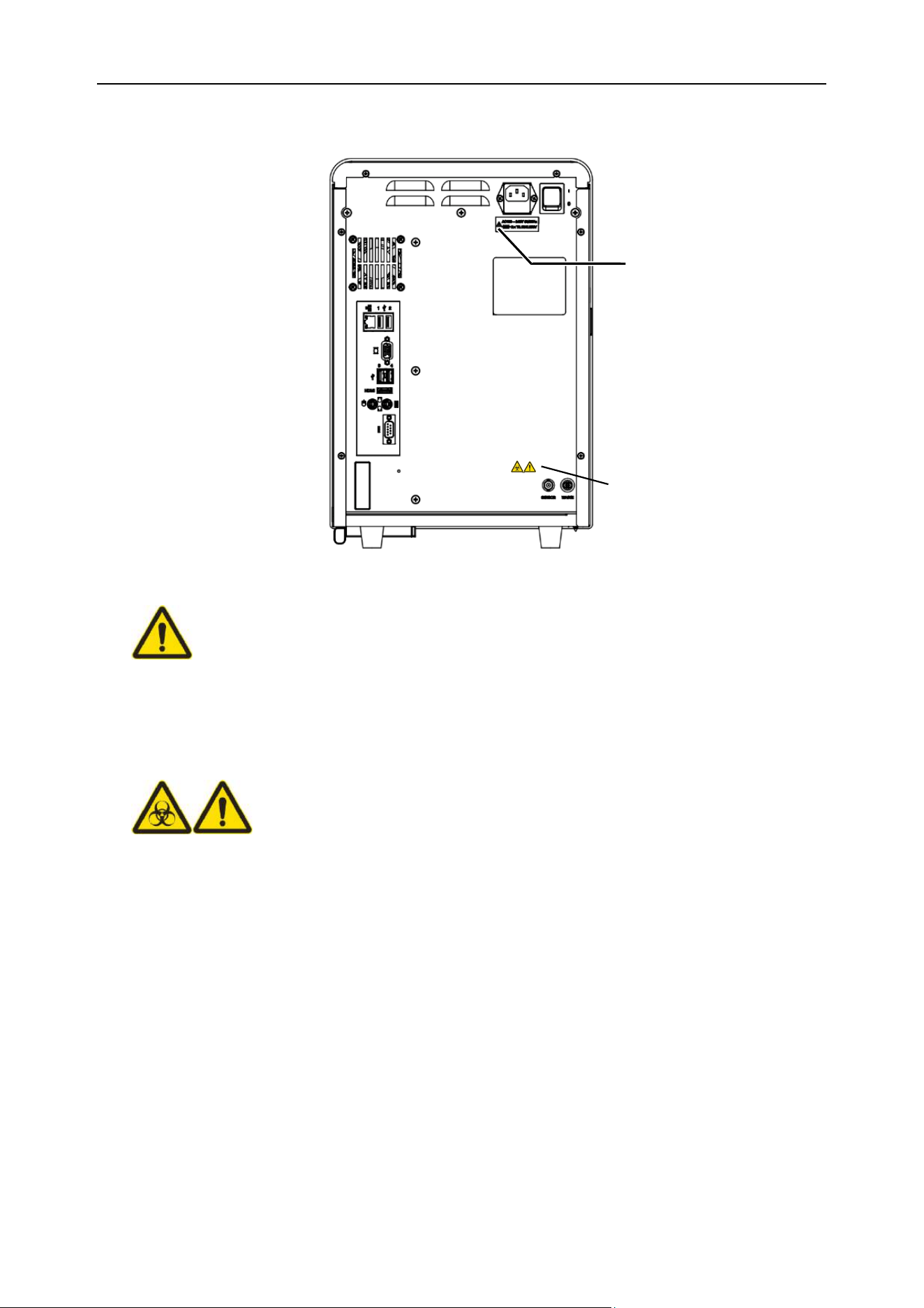
2.2.2 Back of the analyzer
Figure 2-2 Back view of the analyzer
(1)
◼ The analyzer must be used in a well-grounded situation.
◼ To avoid electric shock, be sure to disconnect the power before maintenance.
◼ To prevent fire, please use the fuse of the specified model and its rated current.
(2)
◼ There may be a risk of infection. In principle, all parts and surfaces of the analyzer should
be considered as a risk of infection.
◼ To prevent the waste liquid from polluting the environment, it is prohibited to pour the waste
directly into the sewer line. The waste liquid must be biologically or chemically processed
before it can be discharged into the sewer line or directly discharged into the drainage
system with biological pollution waste liquid processing. Hospitals and laboratories are
obliged to comply with the relevant regulations of the environmental protection department
of the local government.
(1)
(2)

Chapter 2 Safety Information
10
2.3 Computer virus protection
Although our analyzer has passed computer virus checks before they are sold, certain user
environments may still make them vulnerable to computer viruses via the Internet or other means.
Therefore, we recommend that users take appropriate anti-computer virus measures.
WARNING
⚫ Except for the running software of the analyzer, it is forbidden to install any other
software.
⚫ Forbid the function of checking file access.
⚫ When using USB drive, CD-R or other external storage devices, you must check for
viruses before use.
⚫ Do not download files irrelevant to the use of the analyzer from the Internet or other
download sources.
⚫ The user shall be responsible for failures caused by using other software.
2.4 Installation, maintenance, repair and operation
Note
⚫ Please unpack, install and confirm whether the initial operation is normal under the
guidance of the technical service personnel of BIONOTE. Please refer to Chapter 4 for
installation details.
⚫ Do not insert the power plug of the analyzer into a socket with the non-specified
voltage.
⚫ Please note that the analyzer must be grounded. Otherwise, it may cause a fire or
electric shock.
⚫ The analyzer can only be used by trained personnel.
⚫ Please take protective measures when operating the analyzer to avoid infection.
Chapter 2 Safety Information
11
⚫ In the event of a malfunction of the analyzer, the operator must deal with it within the
scope that is specified in the operation manual. For other faults handling or
maintenance, please contact BIONOTE.
⚫ When connecting any peripheral devices (host, printer, etc.), the power supply should
be cut off first. If an option is connected after the analyzer is started, the analyzer may
stop abnormally.
⚫ This device complies with part 15 of the FCC Rules. Operation is subject to the
following two conditions:
(1) This device may not cause harmful interference
(2) This device must accept any interference received, including interference that
may cause undesired operation.
2.5 Reagents, quality control, waste liquid, waste materials and other waste disposal
⚫ All objects (samples, control materials, calibrators, reagents, waste liquid, etc.), as
well as areas in contact with these substances have potentially biological infectious
hazard. Operators should abide by laboratory safety operation regulations and wear
personal protective equipment (such as laboratory guards, gloves, etc.) when
touching related objects and areas in the laboratory.
⚫ If the host leaks, the leaked liquid has biological infectious hazard.
WARNING
⚫ The matching reagents are conductive. If accidentally spilled on the near of the wire
or the analyzer, it may cause electric shock, please turn off the analyzer, unplug the
power cord and wipe the reagent.
⚫ The matching reagent contains sodium hypochlorite. If it contacts the surface of the
analyzer, it may cause corrosion. Please wipe it off with a damp cloth immediately.

Chapter 2 Safety Information
12
Note
⚫ When handling quality control reagents, please follow the instructions on the label of
the control substances.
⚫ Please dispose of waste liquid, reagents, consumables and analyzer as medical
waste, infectious waste and/or industrial waste in accordance with local laws and
regulations.

13
Chapter 3 System Overview
Welcome to read the manual of the Vcheck U3. This manual includes the operation and maintenance
instructions and precautions of the analyzer. To maintain the good performance of the analyzer, the
operation and maintenance must be carried out in accordance with this manual.
3.1 Range of application
The Vcheck U3 (hereinafter referred to as the analysis system) is only used for the urine test for
mammalian urine samples, especially for dogs and cats. Urine samples from other species may be
testable on this analysis system, but it hasn’t been validated.
3.2 Test results
3.2.1 Chemical test results
The analysis system uses adapted urine test strips to detect vitamin C, white blood cells, ketone
bodies, nitrite, urobilinogen, bilirubin, protein, glucose, urine specific gravity, occult blood, pH,
creatinine, and urine calcium, microalbumin in dog’s and cat’s urine, at the same time can provide
protein and creatinine ratio parameters (UPC).
3.2.2 Sediment test results
The analysis system reports both quantitative and semi-quantitative results.
Quantitative Results.
NO.
Parameter
Range
Reference range
Units
1
Red Blood Cells
0-1000
0–15
/μL
2
Dysmorphic Red Blood Cells
0-500
0
/μL
3
White Blood Cells
0-1000
0–15
/μL
4
Squamous Epithelial Cells
0-50
0–5
/μL
5
Non-Squamous Epithelial Cells
0-50
0–5
/μL
6
Renal Tubular Epithelium Cells
0-50
0
/μL
7
Hyaline Casts
0-5
0–1
/μL
8
Pathological Casts
0-5
0
/μL
Chapter 3 System Overview
14
Semi-quantitative Results
NO.
Parameter
Semi-quantitative Results
1
Calcium Oxalate Crystals
-(5)
+(25)
++(100)
+++(250)
++++
2
Uric Acid Crystals
-(5)
+(25)
++(100)
+++(250)
++++
3
Struvite Crystals
-(5)
+(25)
++(100)
+++(250)
++++
4
Unclassified Crystals
-(5)
+(25)
++(100)
+++(250)
++++
5
Bacteria Rods
-(5)
+(250)
++(500)
+++(1000)
++++
6
Bacteria Cocci
-(5)
+(250)
++(500)
+++(1000)
++++
7
Fungus
-(5)
+(25)
++(100)
+++(250)
++++
8
Sperm
-(5)
+(25)
++(100)
+++(250)
++++
3.2.3 RBC morphology test item
The analysis system can detect and display the mean corpuscular volume (MCV), red cell distribution
width (RDW-CV), abnormal red blood cell ratio (R-RATE) and red blood cell volume distribution
histogram.
3.2.4 Urine physical test item
The analysis system can detect urine conductivity and osmotic pressure.
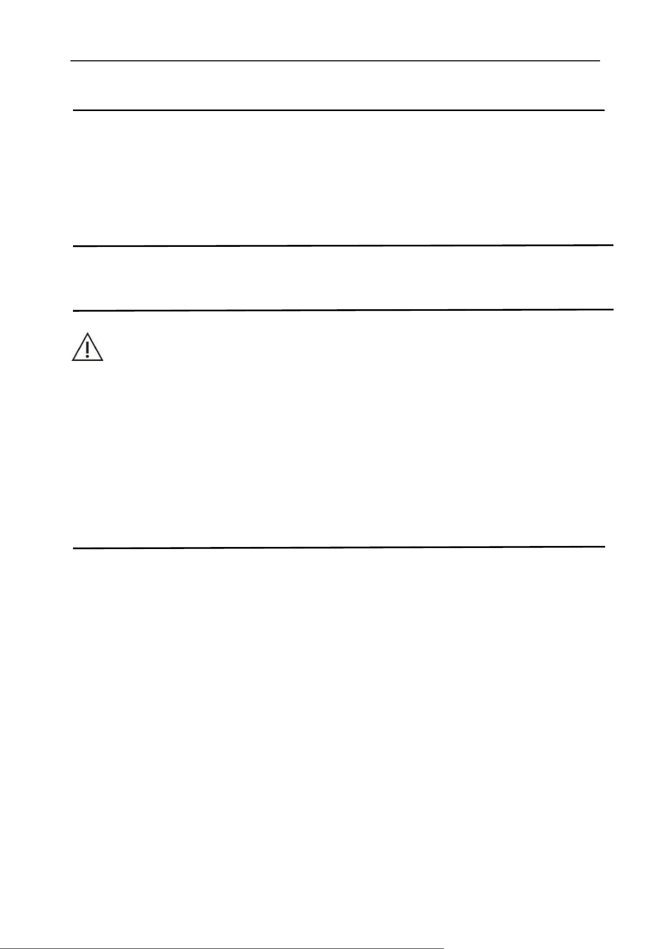
*External accessories are omitted in this figure
Figure 3-1 Analysis system appearance diagram
Chapter 3 System Overview
15
Note
⚫ This analysis system is used for clinical examination analyzer. When making clinical
judgments based on analysis results, veterinarians are required to consider clinical
examination results or other test results at the same time.
3.3 Analyzer Composition
WARNING
⚫ Before running the host, be sure to check that all doors/covers/plates are intact and
will not open or loosen during operation.
⚫ This analysis system is a small and medium-sized analyzer with light weight. If the
analysis system needs to be carried out, it is recommended to be carried by one
person, and the corresponding safety regulations and appropriate tools should be
used when carrying.
Chapter 3 System Overview
16
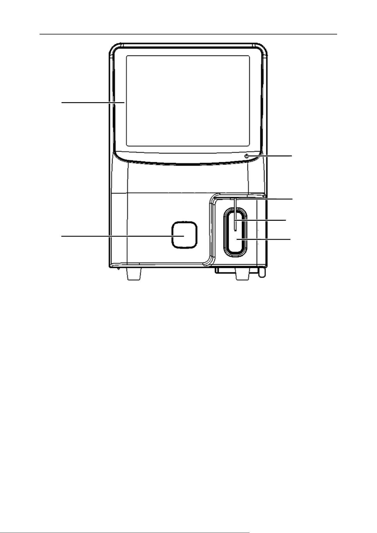
Figure 3-2 Front view of the host
(1)-Touch type colorful LCD display screen (2)-Touch power button (3)-Status indicator
(4)-Sample probe (5)-Test sampling button (6)-Chemistry test door
3.3.1 Touch type colorful LCD display screen
It is used to display the interface and test information, and the user can operate the analyzer through
the touch screen to perform the corresponding work.
3.3.2 Touch power button
The “Touch power” button is located at the right side of the lower part of the display screen and is
used to turn the analyzer on and off.
3.3.3 Status indicator
The indicator is used to show the working status of the analyzer. The status description is as Table
3-1:
(4)
(6)
(3)
(1)
(2)
(5)

Chapter 3 System Overview
17
Table 3-1 Indicator description
Indicator status
Analyzer status description
Red, constant light
A warning or error occurred and was not resolved
Pale Blue, constant light
Idle (status to be tested)
Pale Blue, flashing
Running (test status) / initialization (self-inspection process)
Blue, flashing
Turning on or off
Blue, constant light
The system is turned off (main power is not cut off)
3.3.4 Sample probe
It’s used to collect urine samples for the sediment test.
3.3.5 The test sampling button
It is used to start the urine sediment analysis and detection.
3.3.6 Chemistry test door
The entrance and exit of the test strips for urine chemistry test can prevent dust and debris from
entering the inside of the analyzer.
Note
⚫ During chemistry testing, when the internal test strip bracket is ejected, the cabin
door will open and extend out of the machine body. Sufficient space should be
reserved in front of the cabin door. For details, please refer to "Chapter 4: 4.3
Installation requirements"
Chapter 3 System Overview
18
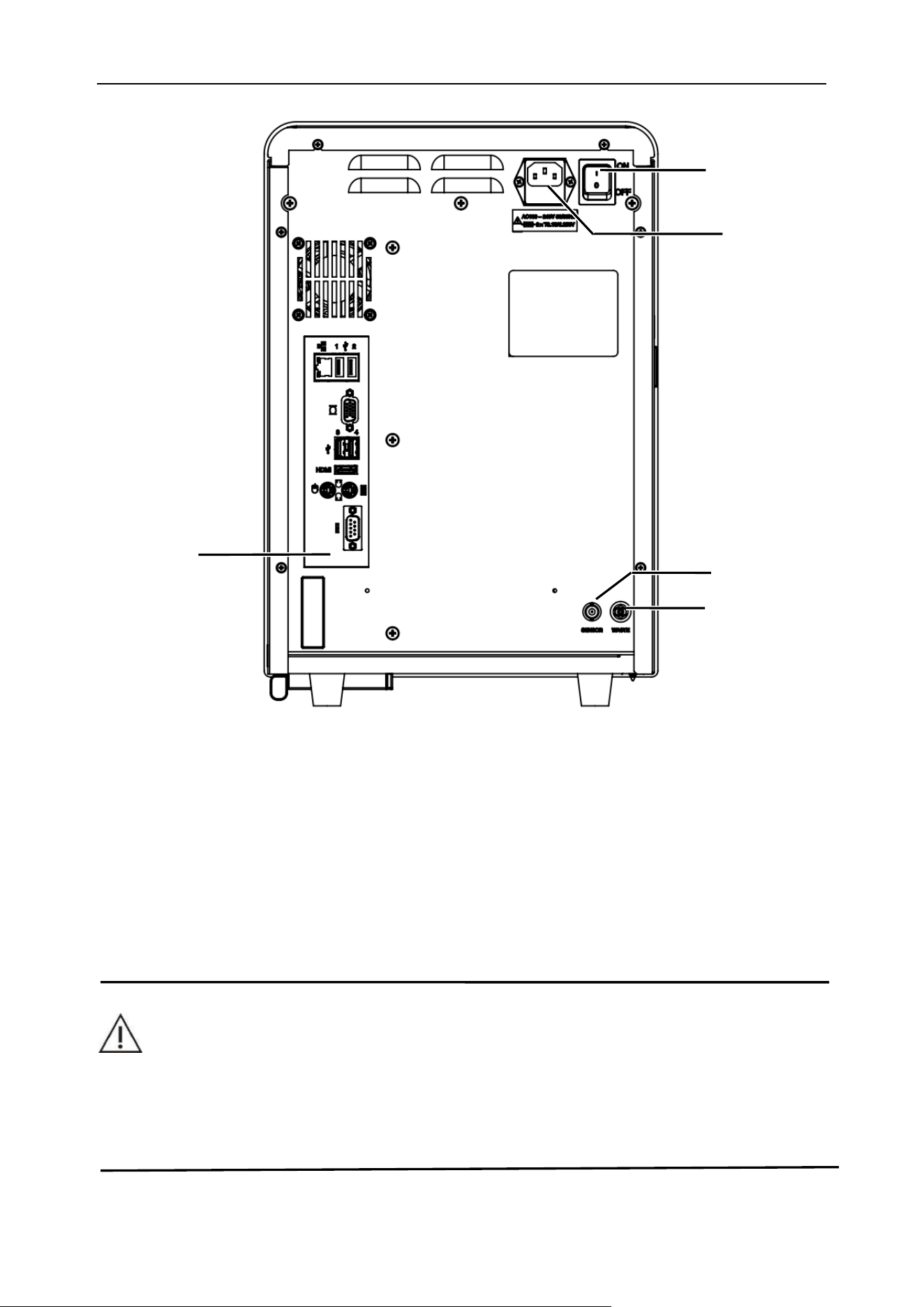
Figure 3-3 Back view of the host
(1)-Power switch (2)-Power interface (3)-Input/output interface
(4)-SENSOR (5)-WASTE
3.3.7 Power switch
The power switch is located on the upper left side of the back of the analyzer, and it is used to turn on
or off the main power of the analyzer.
CAUTION
⚫ Do not repeatedly turn on and off the main power switch within a short period of time.
Otherwise, it may overload the fuse and cause it to blow.
(3)
(5)
(1)
(4)
(2)
Chapter 3 System Overview
19
3.3.8 Power interface (with guard filter)
Three-core power socket, using attached power cord to supply power. It’s located on the upper side
of the back of the analyzer, and it is used to supply power to the analyzer.
Please use 250V 3.15A (time-delay type low blocking capacity) fuse.
3.3.9 Input/output interface
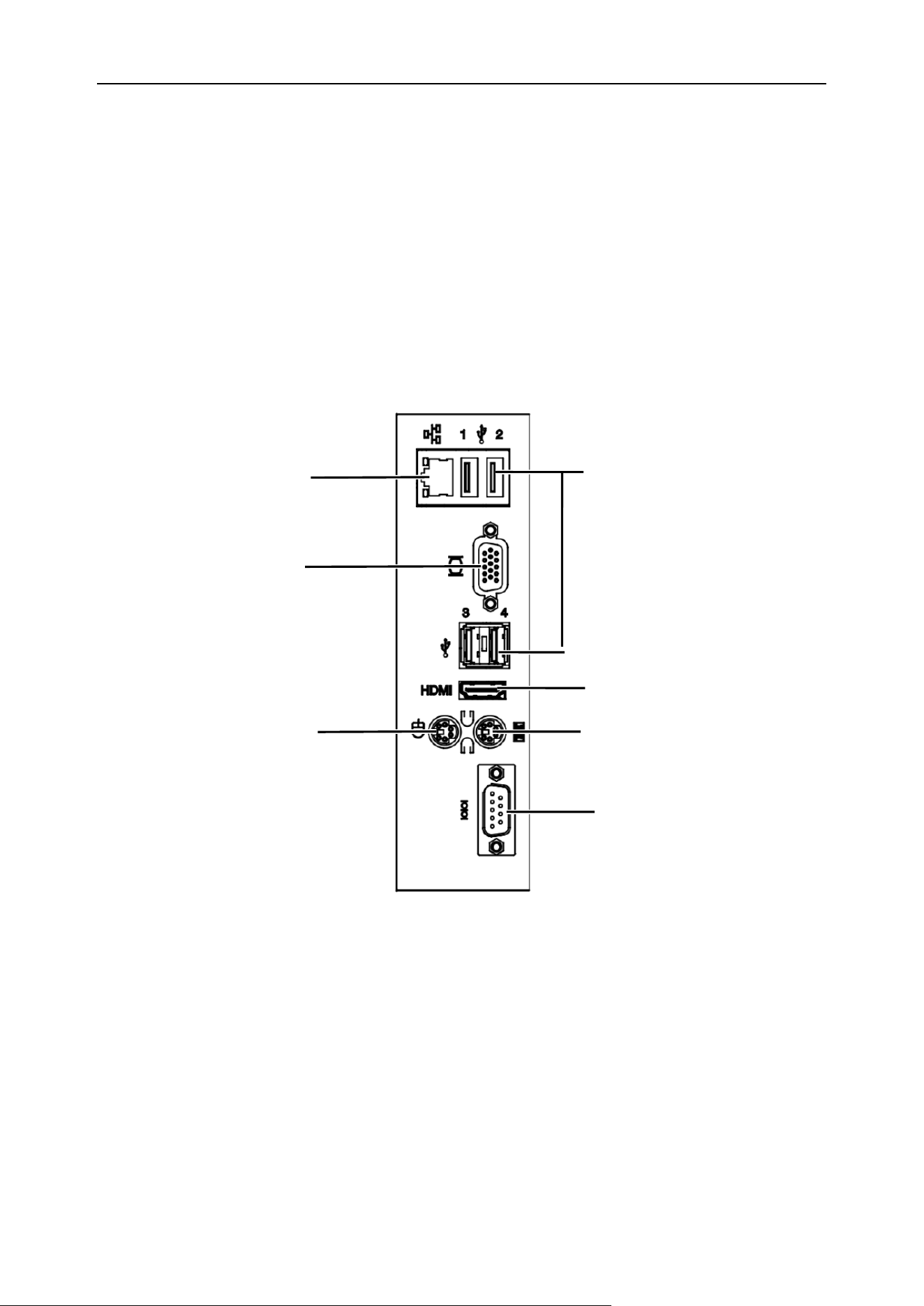
The input/output interface of the analyzer is defined as follows:
(1) Internet interface (2) USB 1, USB 2, USB 3, USB 4 (3) VGA video interface
(4) HDMI interface (5) Keyboard interface (6) Mouse interface (7) Serial port COM
Figure 3-4 Input and output interface
(1) Internet interface: Used to connect a host to a computer. Network cable length <3 m.
(2) USB 1, USB 2, USB 3, USB 4: Used for debugging instruments program upgrade.
(3) VGA video interface: Used for debugging instruments.
(4) HDMI interface: Used for debugging instruments
(5) Keyboard interface: Used for debugging instruments.
(6) Mouse interface: Used for debugging instruments.
(7) Serial port COM: Used for debugging instruments.
(1)
(5)
(4)
(6)
(3)
(2)
(7)
Chapter 3 System Overview
20
The VGA video interface, HDMI interface, keyboard interface, mouse interface, and serial port are not
commonly used functional interfaces of the analyzer and cannot be used normally. If you have any
questions or requirements, please consult BIONOTE or BIONOTE’s designated agent.
3.3.10 SENSOR
Connecting the waste liquid sensor, the waste liquid sensor interface, is used to test whether the
waste liquid bottle is full. If the waste liquid is directly discharged through the waste liquid pipeline,
please turn off the waste liquid detection function in the software setting interface.
3.3.11 WASTE
The waste liquid interface is connecting the waste liquid pipeline to discharge waste liquid.
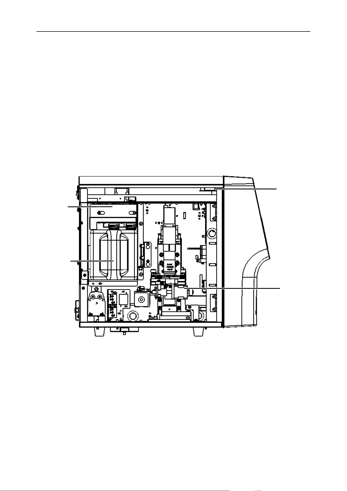
Figure 3-5 Left view of the host
(1) Speaker (2) Microscope shooting system (3) Reagent pumping components
(4)Reagent
3.3.12 Speaker
It will give a voice announcement. And it is used to remind system test, fault and maintenance and so
on.
*Left door
panel omitted
(3)
(1)
(2)
(4)
Chapter 3 System Overview
21
3.3.13 Microscope shooting system
The microscopic shooting system is mainly composed of a light source device, an objective lens, a
lens cone, a camera and a focusing platform. It mainly completes the presentation, magnification,
shooting and recording of the sample to be tested in the counting chamber.
3.3.14 Reagent pumping components
It is used to automatically extract the solution in the reagent.
3.3.15 Waste liquid pumping component
It is used to discharge the waste liquid in the host.
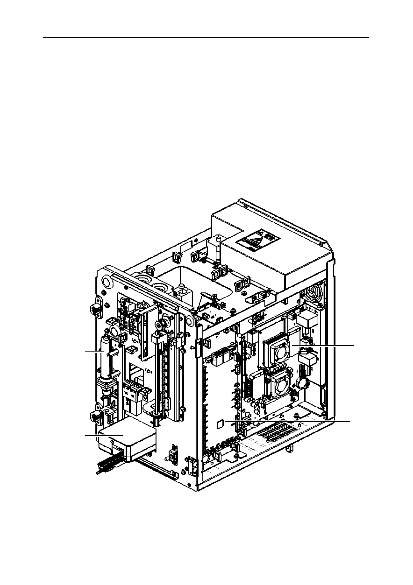
Figure 3-6 Side view of the host axis
(1) Industrial control board (2) Fluid system control board (3) Syringe assembly
(4)
(1)
(2)
(3)
Chapter 3 System Overview
22
(4) Chemistry test device
3.3.16 Industrial control board
It consists of a set of multi-core processors. It is used to undertake the calculation tasks of picture
processing to ensure rapid batch processing of sample pictures.
3.3.17 Fluid system control board
This part controls the operation of the entire analyzer. Responsible for the opening and closing of
various valve bodies and pump bodies in the fluid system, as well as the actions of the microscope
shooting system. To ensure that the sample is smoothly drawn into the counting chamber to form a
sediment, to facilitate image collection.
3.3.18 Syringe assembly
It is used to complete sample collection and transport the sample to the test station.
3.3.19 Chemistry test device
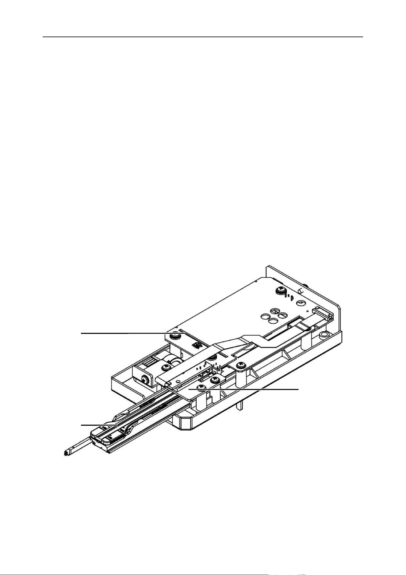
Figure 3-7 Chemistry test device
(1)Control circuit board (2) Detector head (3) Test bracket
(1) Control circuit board
Responsible for controlling the movement of the chemistry drive motor, reading the position
(3)
(2)
(1)

Chapter 3 System Overview
23
information of the test bracket, converting and calculating the photoelectric signal of the detector
head, and performing information exchange with the host computer.
(2) Detector head control board
Responsible for the emission of multiple wavelengths and reception of reflected light, and it is used to
detect the color of the test paper.
(3) Test bracket
It’s used to place test strips.
Note
⚫ The matched BIONOTE test strips should be used for the urine chemistry test, and
the test strips should be put in place.
⚫ It should be ensured that the sample volume is sufficient when dropping the sample
to meet the chemical reaction of the test strip.
⚫ When performing the test strip dipping method, a paper towel should be used to
absorb the excess urine on the test strip.
3.4 Reagent
Note
⚫ To maintain the good test performance of the analyzer, BIONOTE has configured
special reagents for the analysis system. These reagents are under factory inspection
according to product standards and all are qualified. The nominal measurement
indicators of the analyzer are all obtained under the conditions of using Vcheck U3
special reagents. The use of non-BIONOTE reagents will affect the performance of the
analyzer, cause serious measurement errors, and may cause analyzer faults.
⚫ All reagents must be stored at room temperature in order to maintain the most ideal
chemical performance. All reagents should be stored away from excessive cold,
overheating and direct sunlight; if the temperature is lower than 0°C, the reagents will
freeze, causing the chemical performance and electrical conductivity performance of
the reagent’s changes.

Chapter 3 System Overview
24
⚫ During use, in order to minimize the evaporation of the reagent and reduce the
pollution of the reagent from the outside, the container with the reagent should be
tightly closed with the container lid, and the pipeline is inserted into the reagent
through the container lid. However, the quality of reagents will change over time, and
all reagents must be used within the validity.
3.4.1 Detergent 1
Detergent 1 is mainly used for daily cleaning of the fluid system, counting chamber, and sample probe.
And it can be used for sample dilution. The cleaning performed after each sample test is all by
detergent 1.
3.4.2 Detergent 2
Detergent 2 has a powerful cleaning effect on the fluid system, counting chamber, and sample probe.
It can be automatically cleaned and automatically maintained without manual operation.
Note
⚫ The matching detergent 1 and detergent 2 have been integrated into an integrated
reagent form, which is convenient for reagent replacement.
⚫ Please use it correctly in accordance with the use and handling precautions of the
reagent package.
⚫ Before discarding the reagent, please seal the opening of the container with the
matching rubber plug to prevent the remaining reagent solution from leaking. You can
also use tape to seal the opening.
3.4.3 Control material and calibrator
Control materials and calibrators are used for quality control and calibration of the analyzer. The
control material is an industrially produced reagent product and used to inspect whether the counting
function of the analyzer is normal. Running quality control every day can monitor the operation of the
analyzer to ensure the reliability of the analysis results. The calibrator is also an industrially produced
reagent product for the calibration of the analyzer. For the use and storage method of control material
and calibrator, please refer to the instructions for use of control material and calibrator.
Chapter 3 System Overview
25
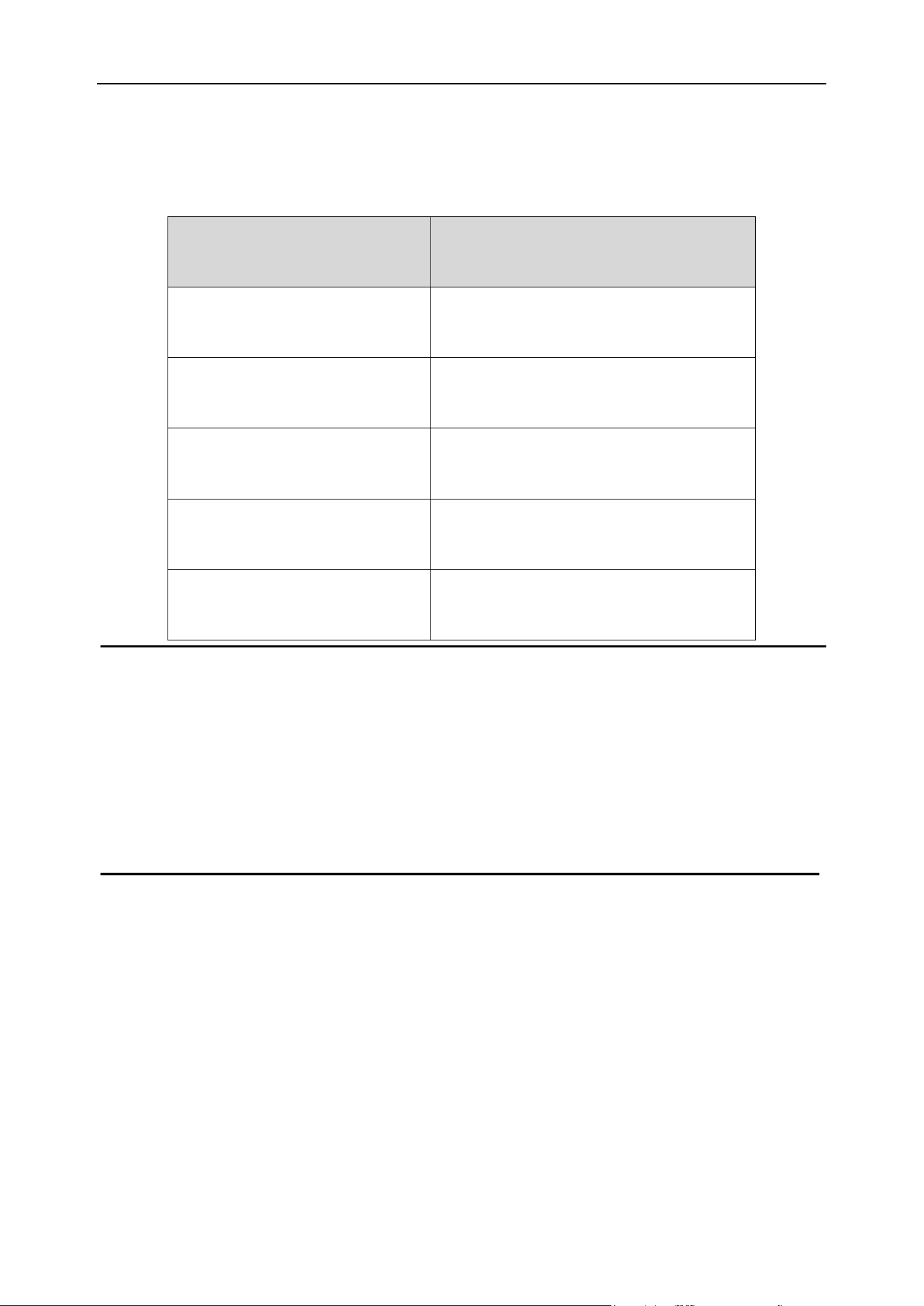
The specifications of adapting reagents and test papers are shown in the following Table 3-2.:
Table 3-2 The specifications of reagents and test papers
Note
⚫ The "control materials" and "calibrators" mentioned in this operation manual refer to
the special control materials and calibrators formulated by BIONOTE. Users need to
purchase them from the agents designated by BIONOTE or BIONOTE.
Name
Model/Specification
Vcheck U Detergent
Sediment reagent
Vcheck U Urine strip
Test strip 14
Vcheck U Sediment Control
Sediment Control
Vcheck U Sediment Calibrator
Sediment Calibration
Vcheck U Chemistry Control
Chemistry Control
26
Chapter 4 Analyzer Installation
4.1 Overview
To achieve satisfactory clinical results with the performance of the analyzer, the Vcheck U3 must be
installed and debugged by an engineer sent by BIONOTE or an engineer authorized by BIONOTE. It
must be installed and used in accordance with this installation procedure for mobile or relocation use.
WARNING
⚫ The installation conducted by any unauthorized or professionally trained personnel
may cause damage to the analyzer, and such damage is not covered by BIONOTE’s
free warranty. Any person who is not authorized by BIONOTE is not allowed to install
or use this analyzer in a different place.
4.2 Unpack and check
Carefully take out the analyzer and accessories from the packaging box, and save the packaging
materials for future transportation or storage.
1) Please count the accessories according to the packing list.
2) Check for flooding.
3) Check for any mechanical damage.
4) Check all exposed wires, plug-in parts and accessories.
If you have any questions, please contact BIONOTE immediately.
4.3 Installation requirement
4.3.1 Installation space requirement
Analyzer repairs, maintenance, and reagent require a certain amount of operating space.
Considering that the waste liquid system pipeline behind the host is not squeezed, which affects the
normal discharge of waste liquid, the host installation needs to meet the following requirements:
◼ The reserved space between the left, right side doors of the host and the wall ≥ 40cm
◼ The reserved space between back plate of the host and the wall ≥ 30cm
Chapter 4 Analyzer Installation
27
◼ Reserved space on the front of the host ≥ 20cm
◼ Ensure that there is enough space on the operating table or below to place the waste liquid
container.
CAUTION
⚫ The analyzer should avoid direct sunlight.
⚫ The working environment of the analyzer should avoid supercooling and overheating.
⚫ Because centrifuges, X-ray machines, photocopiers and other equipment will
interfere with the detection results, the working environment of the analyzer should
avoid these equipments.
⚫ During the test, the door lock cannot be opened.
⚫ Do not place the analyzer where it is difficult to disconnect the analyzer.
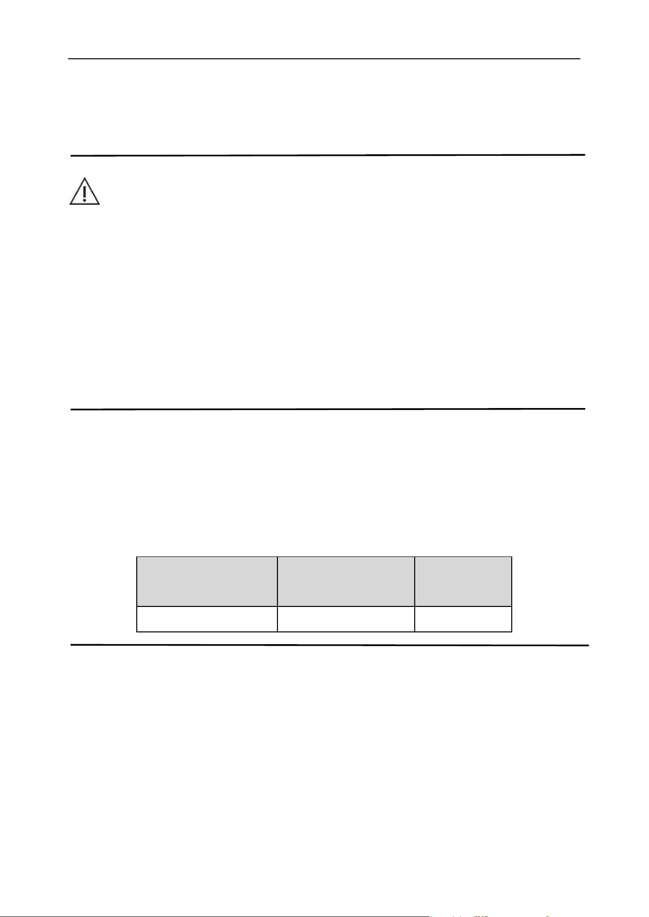
4.3.2 Power requirements
Before installing the analyzer, you must check whether the power supply at the installation site meets
the requirements of the analyzer.
Specific requirements for power supply see Table 4-1
Table 4-1 Power requirements
Optimal working
voltage
Working voltage range
Frequency
220V~
100V-240V~
50/60Hz
Note
⚫ The wire input socket should be well grounded. The user is obligated to ensure the
reliability of the power supply protection place where the analyzer is used.
⚫ Frequent voltage fluctuations will cause the performance and reliability of the
analyzer to decrease. The user should solve this problem before using the analyzer,
such as installing an AC manostat, which needs to be provided by the user.

Chapter 4 Analyzer Installation
28
⚫ Frequent power outages will cause serious degradation of the performance and
reliability of the analyzer. Users should solve this problem before using the analyzer,
such as installing an uninterruptible power supply (UPS).
4.3.3 Working environment requirements
⚫ Ambient temperature: 5–40 ℃
⚫ Relevant humidity: 30–85 %RH
⚫ Altitude: no more than 4000m;
⚫ The environment should be free of dust, mechanical vibration, pollution, large noise sources
and power interference as much as possible.
⚫ It is recommended to evaluate the electromagnetic environment of the studio before
operating the analyzer.
⚫ Do not bring the analyzer close to the source of powerful electromagnetic interference, so as
to avoid affecting the normal operation of the analyzer.
⚫ Choose a well-ventilated location to place the host.
⚫ Do not place the host on an inclined surface.
4.4 Waste liquid pipeline connection
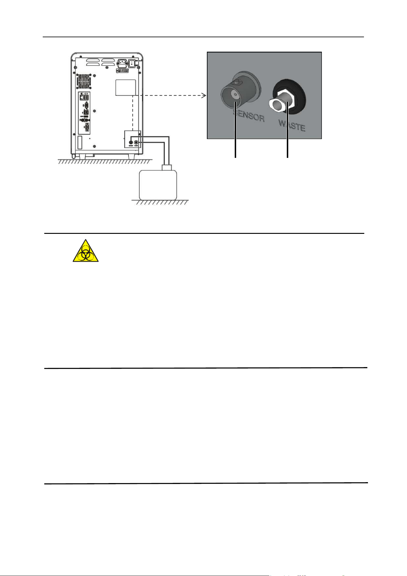
[SENSOR] sensor connector and [WASTE] catheter interface are installed on the rear panel of the
host. To prevent pipeline contamination before the analyzer leaves the factory, a cap is installed at the
waste liquid pipeline interface. The cap should be removed from the catheter interface and stored
carefully during the initial installation.
Take out the waste liquid inlet tube from the reagent box and connect it to the fluid system connector
marked "WASTE" on the rear panel of the analyzer and connect the BNC plug to the socket marked
"SENSOR" on the rear panel. It is recommended that the location of the waste liquid container be
placed under the table and should be at least 50 cm below the surface of the analyzer.
Chapter 4 Analyzer Installation
29
Figure 4-1 Waste liquid (WASTE) inlet tube connection
⚫ To prevent the waste liquid from polluting the environment, it is prohibited to pour the
waste liquid directly into the sewer line. The waste liquid must be biologically or
chemically processed before it can be discharged into the sewer line, or directly
discharged into the drainage system with biological pollution waste liquid processing.
Hospitals and laboratories are obliged to comply with the relevant regulations of the
environmental protection department of the local government.
Note
⚫ After all the pipelines are installed, the pipelines should be in a natural relaxed status,
and cannot be forcibly twisted, discounted, or rotated.
⚫ It is strictly forbidden to use any tools for the installation of all pipeline connectors
⚫ If the waste liquid container is found to be damaged or leaked during installation, it
cannot be used. Please contact your local BIONOTE office or supplier for
replacement or contact BIONOTE directly.
4.5 Power cord connection
Make sure that the power switch of the analyzer is in the OFF status, insert the hole end of the power
Waste liquid
container
SENSOR
WASTE
Chapter 4 Analyzer Installation
30
cord plug into the power socket of the host, and insert the plug of the socket into a grounded 3-pin
power output socket.
4.6 Reagent installation and replacement
Take the special reagent, remove the sealing screw cap and sealing rubber plug of the reagent, open
the door panel on the left side of the host, click the corresponding button operation on the software
interface, push the reagent in place, close the door panel to complete the reagent placement and
installation.
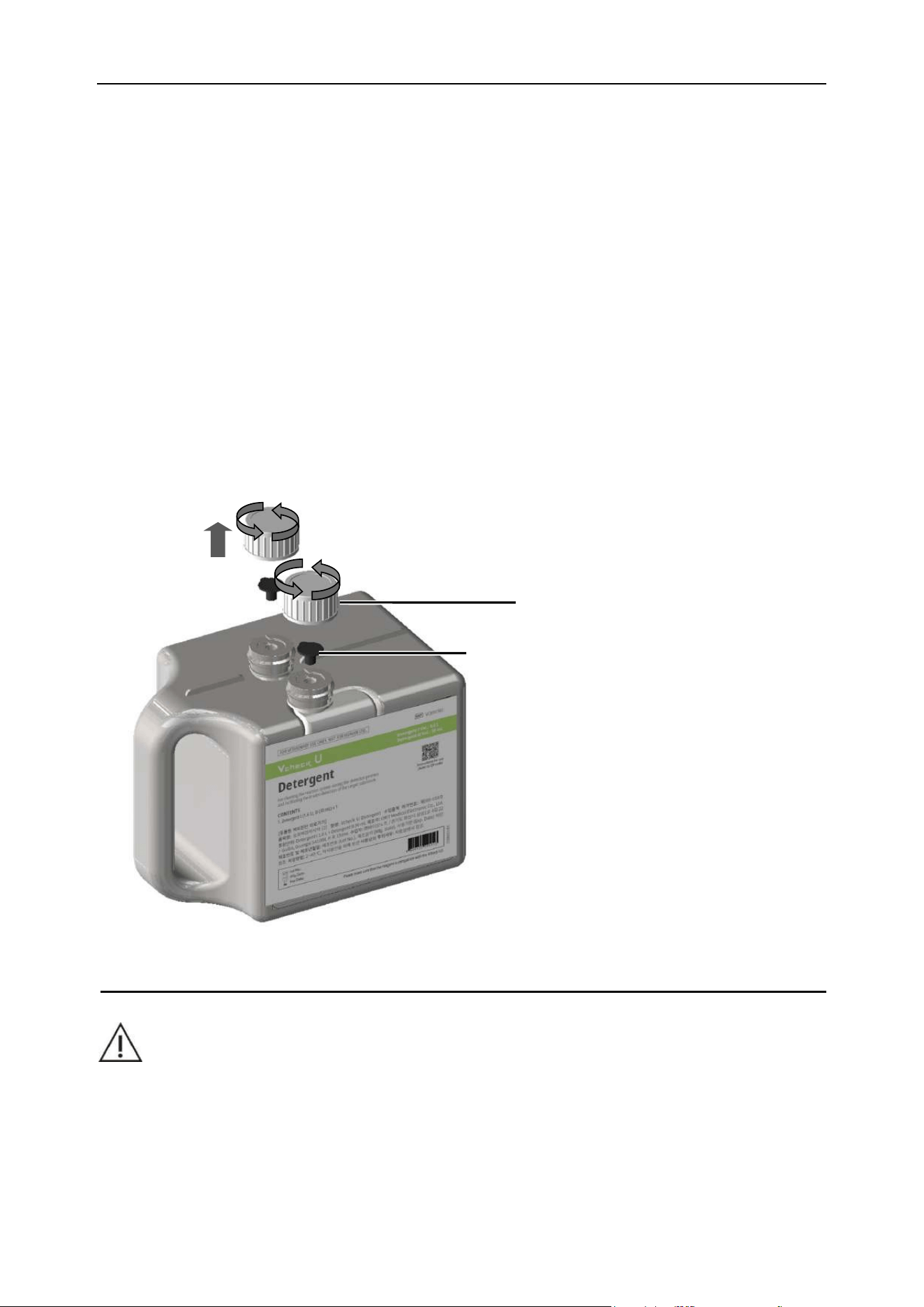
4.6.1 Screw cap and sealing rubber plug disassembly
(1) Unscrew the two screw sealing caps of the reagent counterclockwise, as shown in Figure 4-2;
(2) Pull out the sealing rubber plug, as shown in Figure 4-2.
Figure 4-2 Reagent bottle opening
CAUTION
⚫ When opening the sealing screw cap and rubber plug of the reagent, a small amount
of liquid may emerge. Please wear gloves to operate.
(2)
(1)Screw sealing caps
(2)Sealing rubber
plug
(1)
Chapter 4 Analyzer Installation
31
⚫ If the reagent is found to be damaged, leaking or beyond expiration and other
abnormity during installation, it cannot be used. Please contact your local BIONOTE
office or supplier for replacement or contact BIONOTE directly.
4.6.2 Software side operation
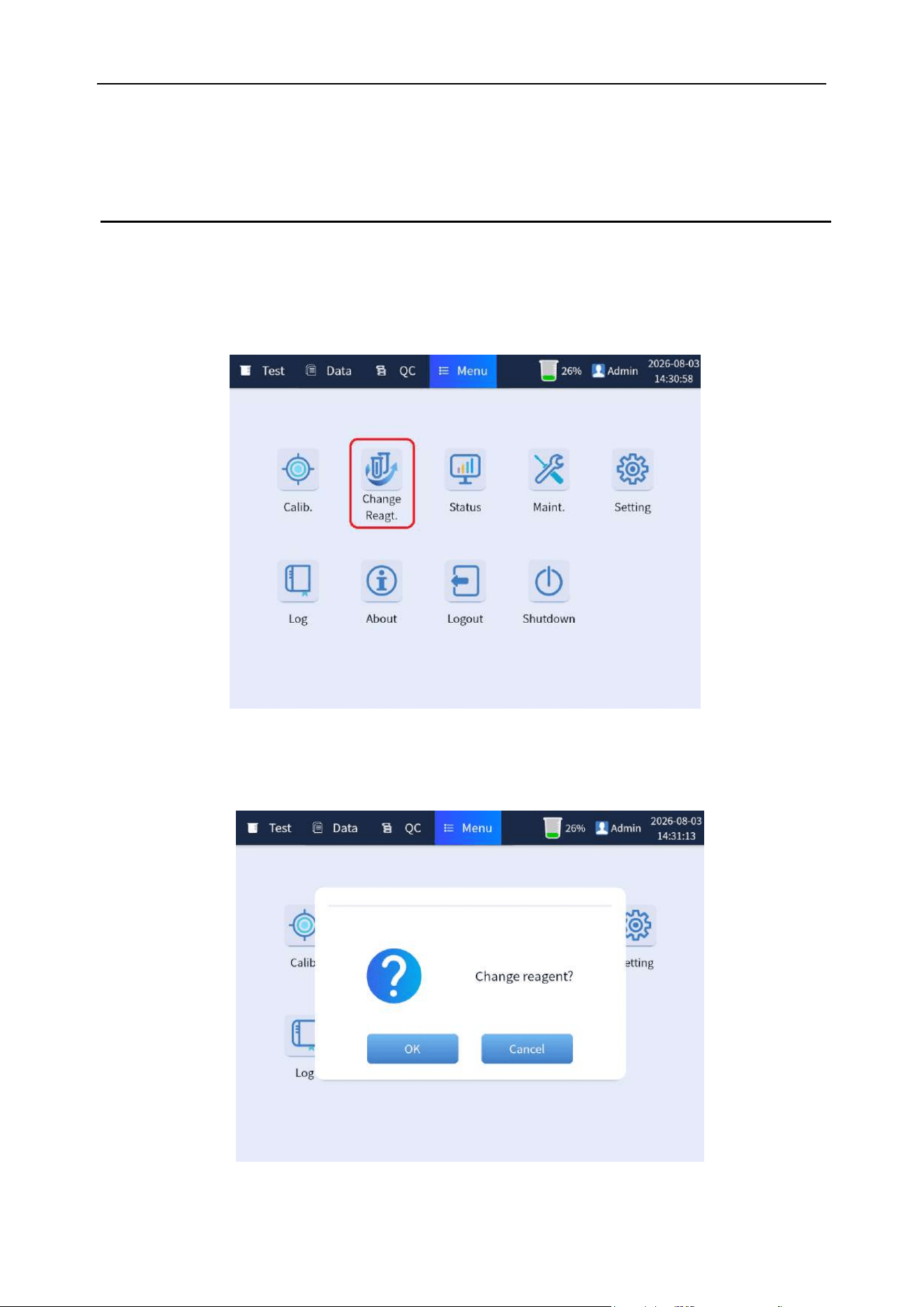
(1) When the analyzer is in the standby status, click [Menu]→[Change Reagt.] button. As shown in
Figure 4-3:
Figure 4-3 Software operation for replacing reagent
(2) The analysis predicts whether to change the reagent, as shown in Figure 4-4:
Figure 4-4 Software operation for replacing reagent
Chapter 4 Analyzer Installation
32
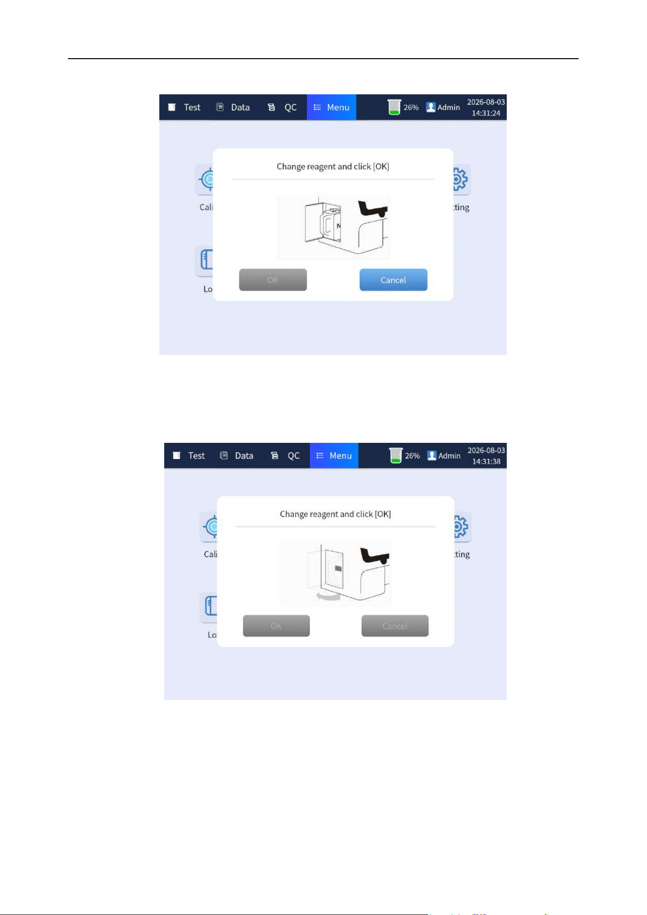
(3) Click [OK] to open the door and take out the reagent or click [Cancel] to undo.
Figure 4-5 Software operation for replacing reagent
(4) According to the animated prompt screen, open the door and take out the reagent. [Cancel]
button is unclickable. As shown in Figure 4-6.
Figure 4-6 Software operation for replacing reagent
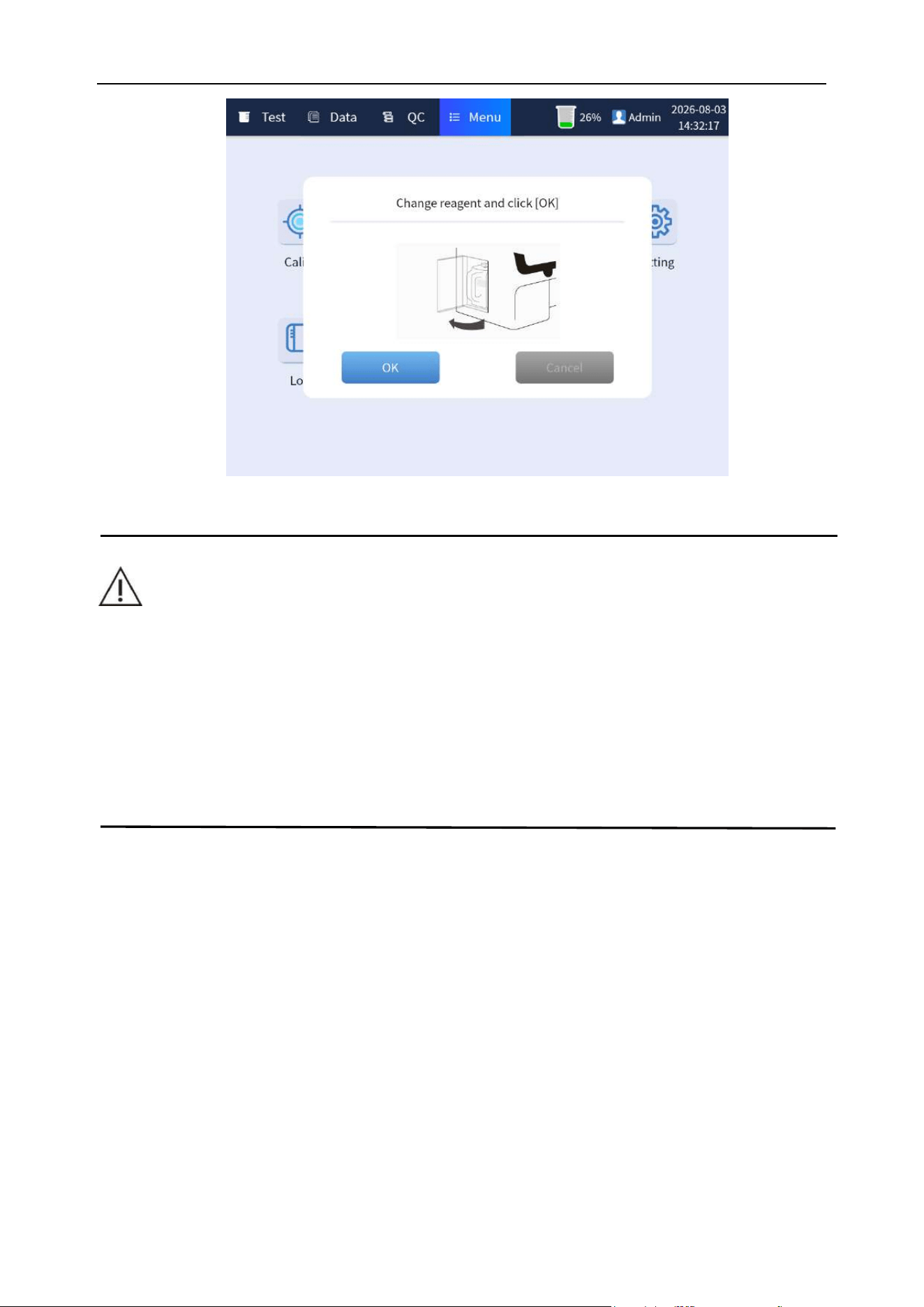
(5) According to the animated prompt screen, push the reagent package into place, and click the
[OK] button. After the analyzer prompts that the replacement is successful, close the door to
complete the replacement. As shown in Figure 4-7:
Chapter 4 Analyzer Installation
33
Figure 4-7 Software operation for replacing reagent
WARNING
⚫ Please use BIONOTE special reagents, otherwise the analyzer may be damaged.
⚫ Replace the removed waste reagents with the original rubber plug and screw cap to
seal the bottleneck to prevent the residual liquid in the bottle from leaking.
⚫ The discarding of the replaced waste reagents shall comply with the relevant
regulations of the environmental protection department of the local government.
34
Chapter 5 Analyzer Setting
5.1 Overview
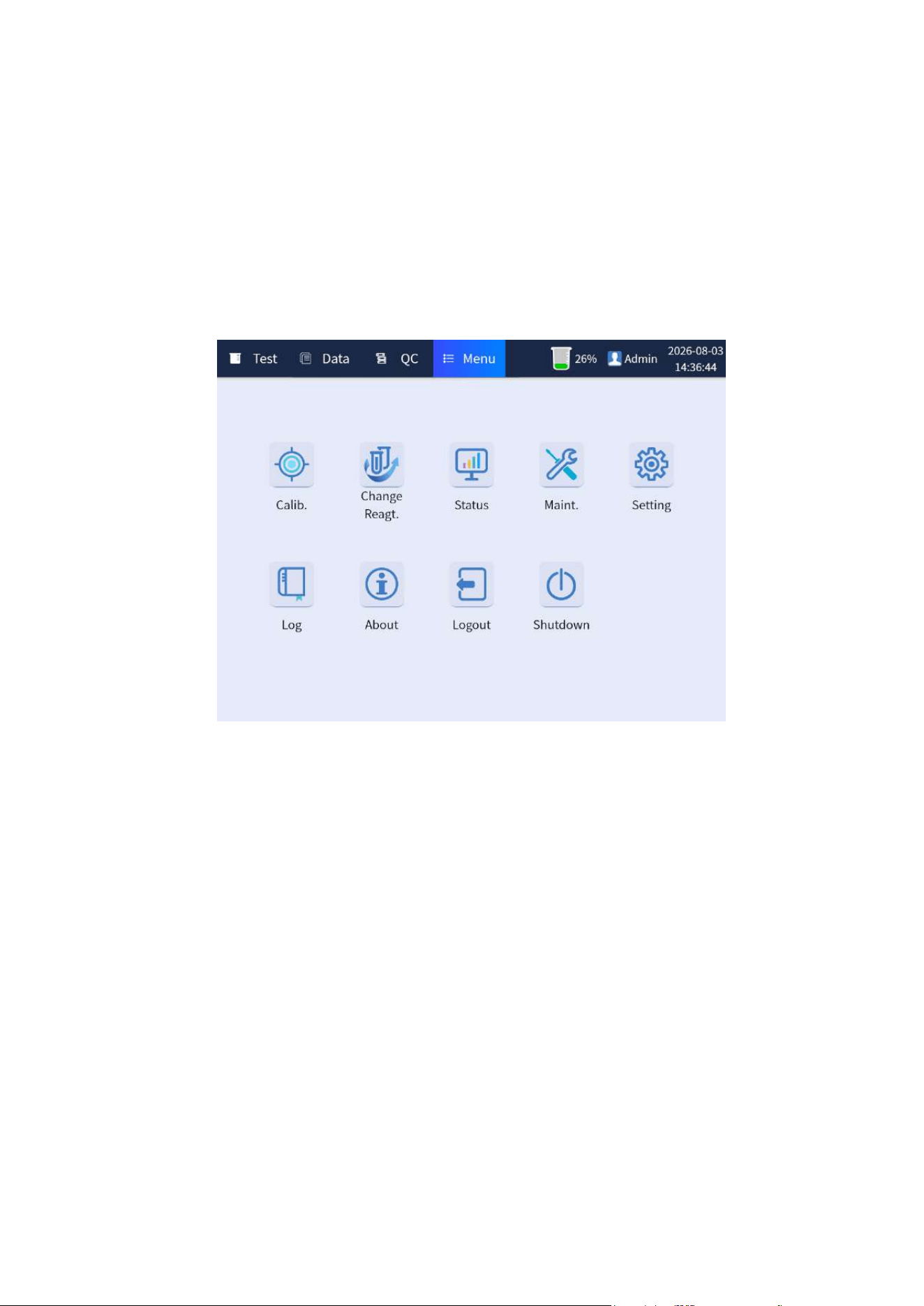
The analyzer settings mainly include [Normal], [Item Setting], [Network], [User Manage], [Debug],
[Dictionary], etc. The setting entry is click the [Menu] button on the main interface to enter the menu
interface, as shown in Figure 5-1. Then click [Setting] again to enter the setting interface.
Figure 5-1 Menu interface
5.2 Normal setting
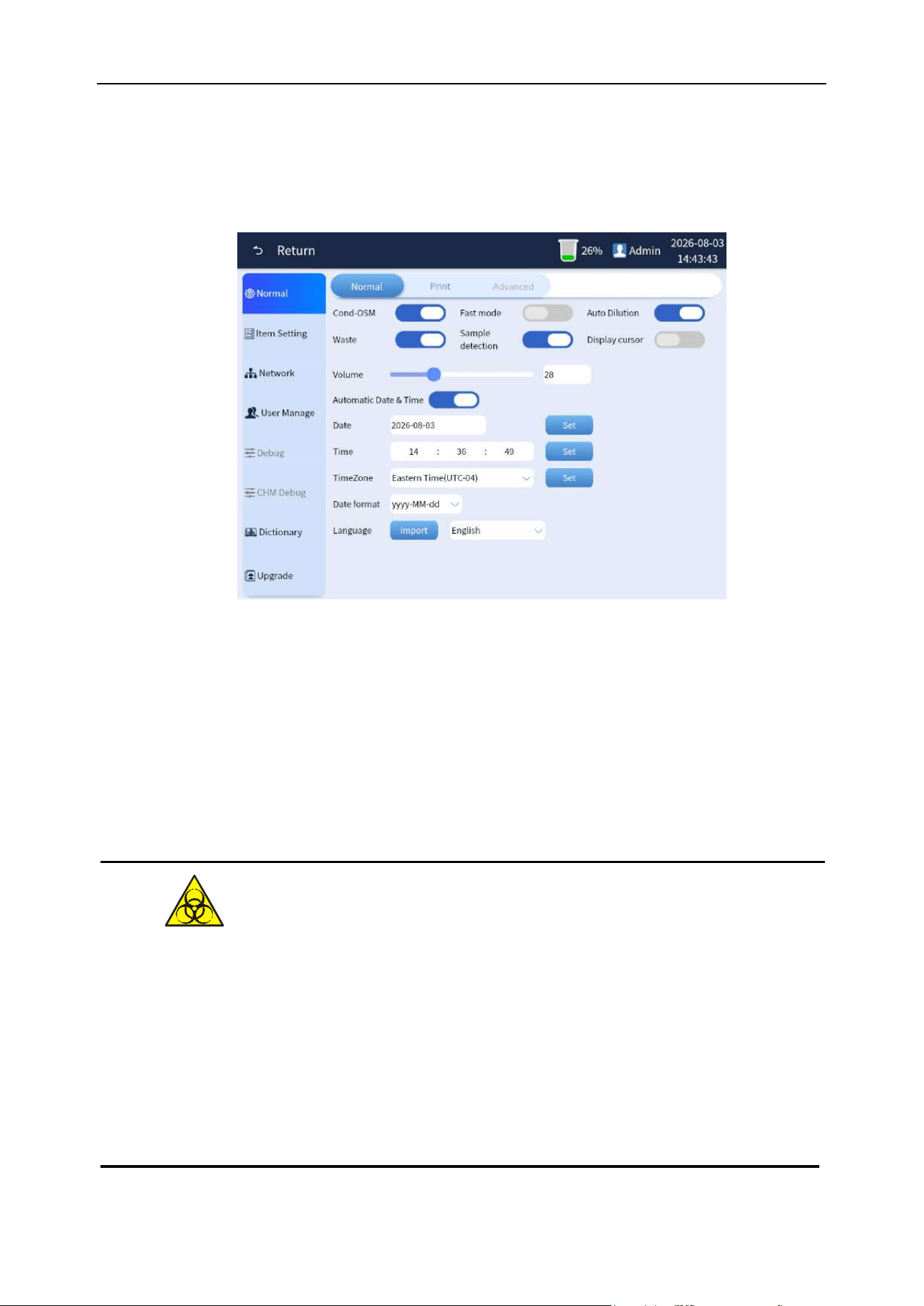
Overview: The normal settings are divided into three setting screens: Normal and print setting, as
shown in Figure 5-2.
Chapter 5 Analyzer Setting
35
5.2.1 Normal
It includes CondOSM, Fast mode, Waste, Auto Dilution, Display cursor, and Sample size and other
switch settings, as shown in Figure 5-2-1.
Figure 5-2-1 General settings interface
(1) Cond-OSM: Used to turn on/off the conductivity test function, it is turned on by default.
(2) Fast mode: Used to turn on/off the fast test mode, it is turned off by default, even if under the
normal mode.
(3) Waste: Used to turn on/off the waste liquid detection function. It is turned on by default. When
the waste liquid is directly drained from the pipeline, this function needs to be turned off,
otherwise it must not be turned off.
⚫ To prevent the waste liquid from polluting the environment, it is prohibited to pour the
waste liquid directly into the sewer line. When the waste liquid is directly discharged
by pipeline, it should be ensured that it is directly discharged into the drainage
system with biological pollution waste liquid treatment. Hospitals and laboratories
are obliged to comply with the relevant regulations of the environmental protection
department of the local government.
Chapter 5 Analyzer Setting
36
(4) Sample detection: Used to turn on/off the sample size detection function of the analyzer, it is
turned on by default.
(5) Auto Dilution:This function is used to enable/disable the automatic dilution and retesting of
high-concentration samples in urine sediment testing. The system has this function enabled by
default.
(6) Display cursor:This function is used to enable/disable the display of the mouse cursor when an
external mouse is connected. By default, the system has this function disabled.
(7) Volume:Adjust the volume of alarm.
(8) Date:Modify the system date. It’s active when “Automatic date & time” button is turned off.
(9) Time:Modify the system time. It’s active when “Automatic date & time” button is turned off.
(10) Time Zone:Modify the system time zone. It’s active when “Automatic date & time” button is
turned off.
(11) Automatic date & time:This function is used to enable/disable the automatic synchronization of
time settings. Please note that this function is only available when the system is connected to the
internet.
(12) Date format:Det the date format displayed in the upper right corner of the software.
(13) Language:Set the language type used by the software.
5.2.2 Print setting
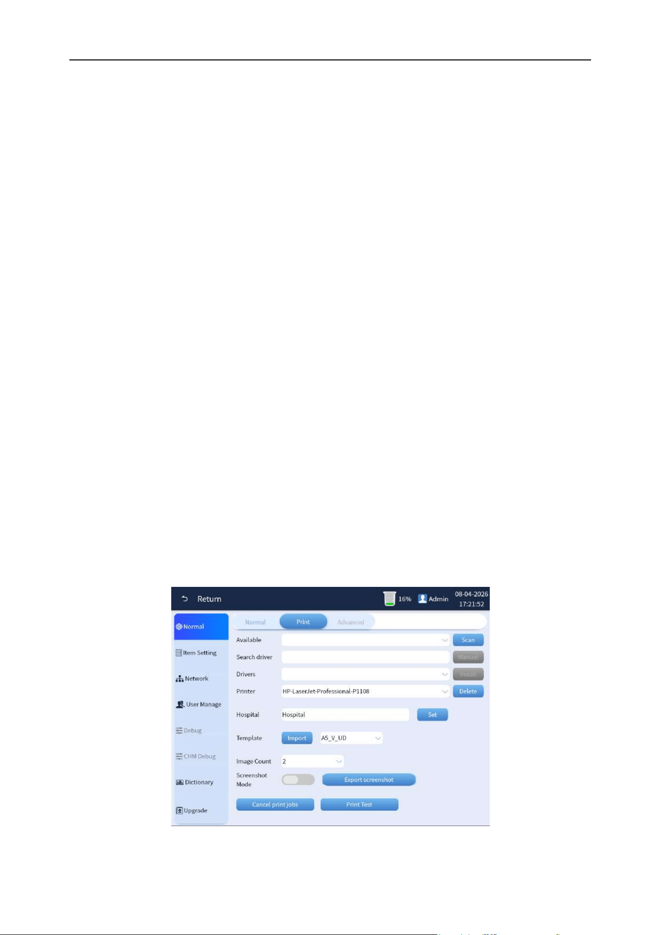
Overview: The available items that can be set in the print setting include the Available, Search driver,
Drivers, Printer, Hospital, Template, Image count, and Auto print, as shown in Figure 5-2-2.
Figure 5-2-2 Print settings interface
Chapter 5 Analyzer Setting
37
(1) Available:Used to scan and display the printers available. After scanning is complete, the
dropdown menu "Drivers" will show the automatically detected driver files.
(2) Search driver:Enter the printer model or relevant name information, and click on "Manual" to
specify the search. The driver files that are found will be displayed on the dropdown menu
"Drivers".
(3) Drivers:After the scanning process is complete, the driver files that are found will be displayed
in the dropdown menu "Drivers". Clicking on the "Install" button will install the selected driver file
from the dropdown menu. Once the installation is successful, the printer will be added to the
dropdown menu "Printer".
(4) Printer:Choose the printer that will be used for printing the results. The available options are the
printers that have been installed.
(5) Hospital:The name of the hospital displayed in the printed results.
(6) Template:The template used to print results.
(7) Image count: Set the maximum number of cell images displayed during printing.
5.3 Item settings
Overview: Set urine chemistry, sediment test item unit, display name, reference value, etc.
5.3.1 Chemistry item settings
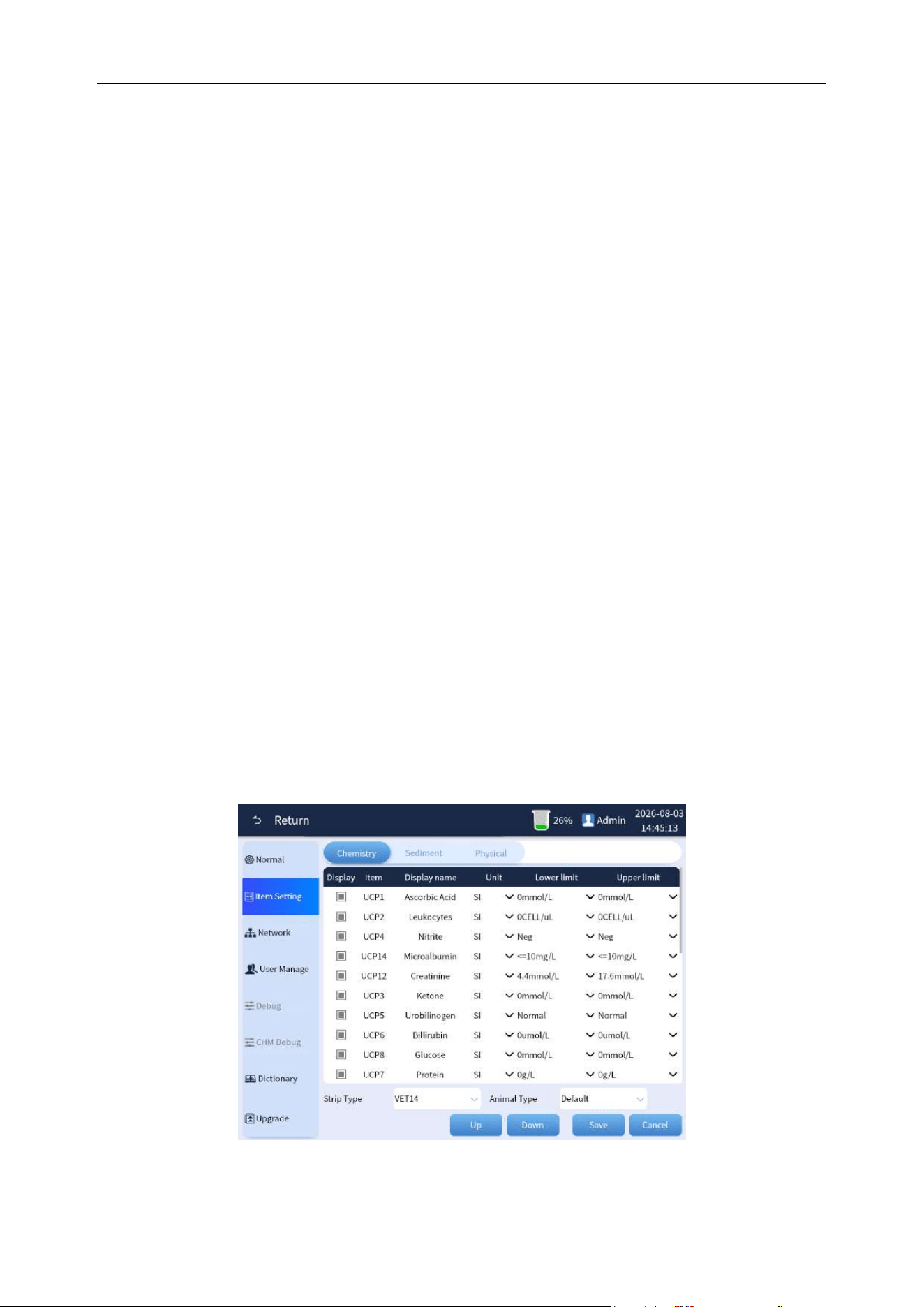
The chemistry item settings include display, item, display name, unit and reference value, which are
used for the interface display setting of the result. The interface is shown in Figure 5-3.
Figure 5-3 Chemistry item settings

Chapter 5 Analyzer Setting
38
1) Display: The selected status means that the item is displayed in the result list, otherwise it is
not displayed.
2) Item: In online mode, the item name is used to match the chemistry result item and can be
edited.
3) Display name: It is used for the result name of the interface display, and it can be edited.
4) Unit: Select the unit displayed by the item, including PLUS, SI, ENG, and CONV. After the
unit is modified, the "reference value" will be automatically updated to the corresponding
setting value.
5) Lower Limit: Indicates the reference value when the unit is used.
6) Upper Limit: Indicates the reference value when the unit is used.
7) Strip Type:Switch to the specified strip type and display the item settings for that strip type.
8) Animal Type:Switch to the specified animal type and display the item settings for the
corresponding strip type.
9) Up: It is used to set the display order of the results on the interface. Select a row and click
the “move up” button to move the row up.
10) Down: It is used to set the display order of the results on the interface. Select a row and click
the “move down” button to move the row down.
11) Save: After modifying the content of the table, the save button will be lit, then click the save
button to save the modified data.
12) Cancel: Abandon the modification or exit the setting interface.
5.3.2 Urine sediment item settings
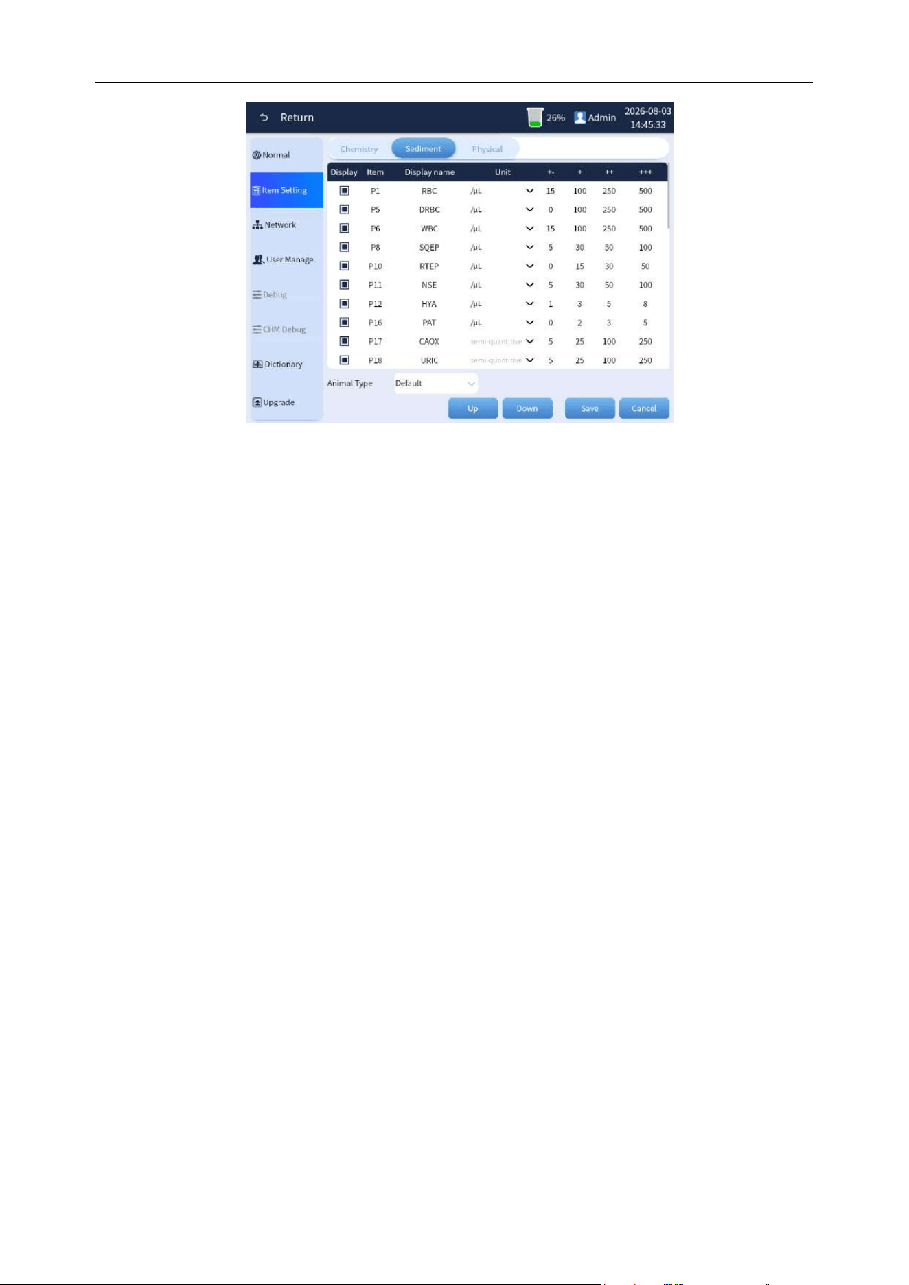
Urine sediment item settings include display, item, display name, unit, "+-", "++", "+++", and "++++",
which are used to set the result interface display, as shown in Figure 5-4.
Chapter 5 Analyzer Setting
39
Figure 5-4 Sediment test item settings
1) Display: The selected status means that the item is displayed in the result list, otherwise it is
not displayed.
2) Item: Item English name and it can’t be edited.
3) Display name: It is used for the result name of the interface display, and it can be edited.
4) Unit: Select the unit displayed by the item, including four units of /uL, /LPF, /HPF, and SQ.
5) "+-", "++", "+++", "++++": Indicates the semi-quantitative threshold, which is divided into four
levels. Fill in the result threshold value in each file. If the test result is less than this value
and the item unit selects "SQ" to display, then the semi-quantitative result of the file will be
displayed. (For example, according to the settings in the figure, if the test RBC result is 60,
then "+1" will be displayed).
6) Animal Type:Display/set the urine sediment item settings corresponding to the specified
animal type.
7) Up: It is used to set the display order of the results on the interface. Select a row and click
the “move up” button to move the row up.
8) Down: It is used to set the display order of the results on the interface. Select a row and click
the “move down” button to move the row down.
9) Save: After modifying the content of the table, the save button will be lit, then click the save
button to save the modified data.
10) Cancel: Abandon the modification or exit the setting interface.
Chapter 5 Analyzer Setting
40
5.3.3 Physical and chemical parameters settings
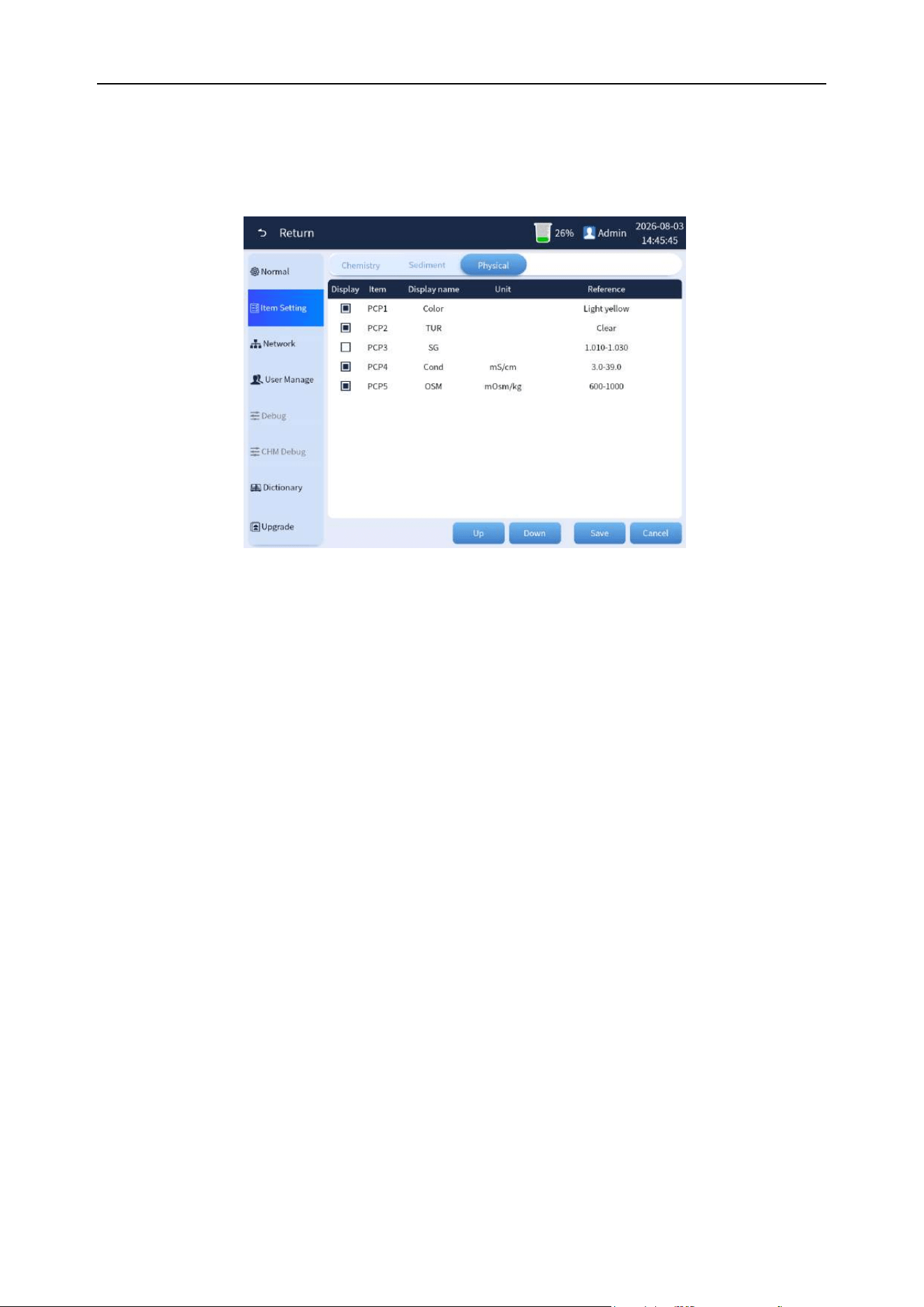
Urine sediment item settings include display, item, display name, unit, and reference value, which are
used to set the result interface display, the interface as shown in Figure 5-5.
Figure 5-5 Physical and chemical parameters item settings
(1) Display: The selected status means that the item is displayed in the result list, otherwise it is not
displayed.
(2) Item: In online mode, the item name is used to match the chemistry result item and can be
edited.
(3) Display name: It is used for the result name of the interface display, and it can be edited.
(4) Unit: Select the unit displayed by the item. After the unit is modified, the "reference value" will be
automatically updated to the corresponding setting value.
(5) Reference: Indicates the reference value when the unit is used.
(6) Up: It is used to set the display order of the results on the interface. Select a row and click the
“move up” button to move the row up.
(7) Down: It is used to set the display order of the results on the interface. Select a row and click the
“move down” button to move the row down.
(8) Save: After modifying the content of the table, the save button will be lit, then click the save
button to save the modified data.
(9) Cancel: Abandon the modification or exit the setting interface.
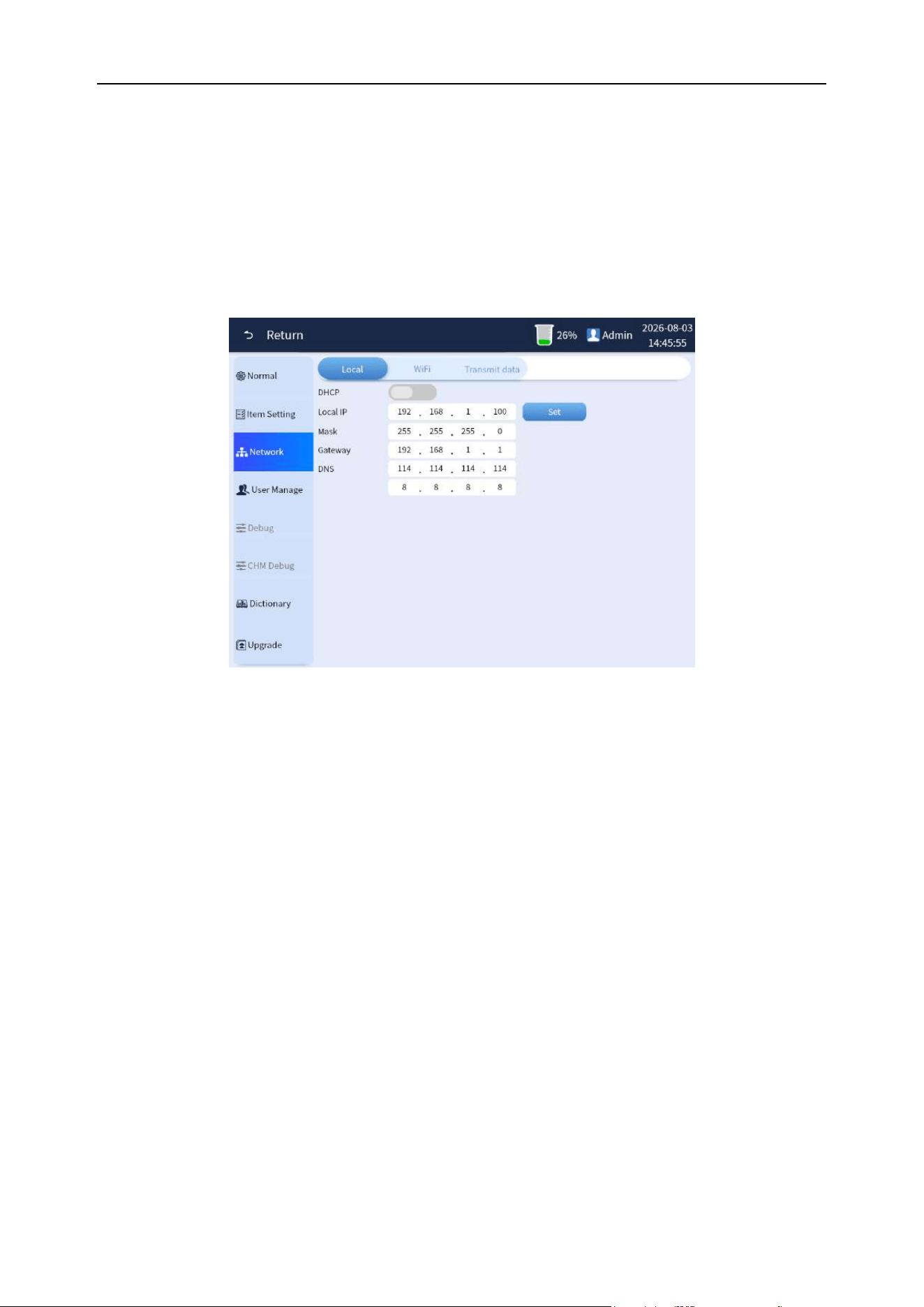
Chapter 5 Analyzer Setting
41
5.4 Network settings
Overview: It includes the screens for Local, and AMS&LIS connection settings.
5.4.1 Local connection
Set the relevant information for local connection. The local connection settings screen includes DHCP,
Outside local IP, Mask, Gateway, and DNS settings. The interface is shown in Figure 5-6-1.
Figure 5-6-1 Local connection
(1) DHCP:Set whether to enable Dynamic Host Configuration Protocol. The default is disabled.
(2) Outside local IP:Set the externally configured IP address in the local network. Please avoid
setting an IP within the 172.20.65.0 network segment, as it is reserved for internal
communication within the analyzer.
(3) Mask:Set the subnet mask for the local network.
(4) Gateway:Set the gateway for the local network.
(5) DNS:Set the DNS for the local network.
5.4.2 AMS&LIS connection
Set the connection Settings used in LIS transmission, including LIS protocol, Send image, Auto send
Settings and LIS IP, as shown in the Figure 5-6-2.
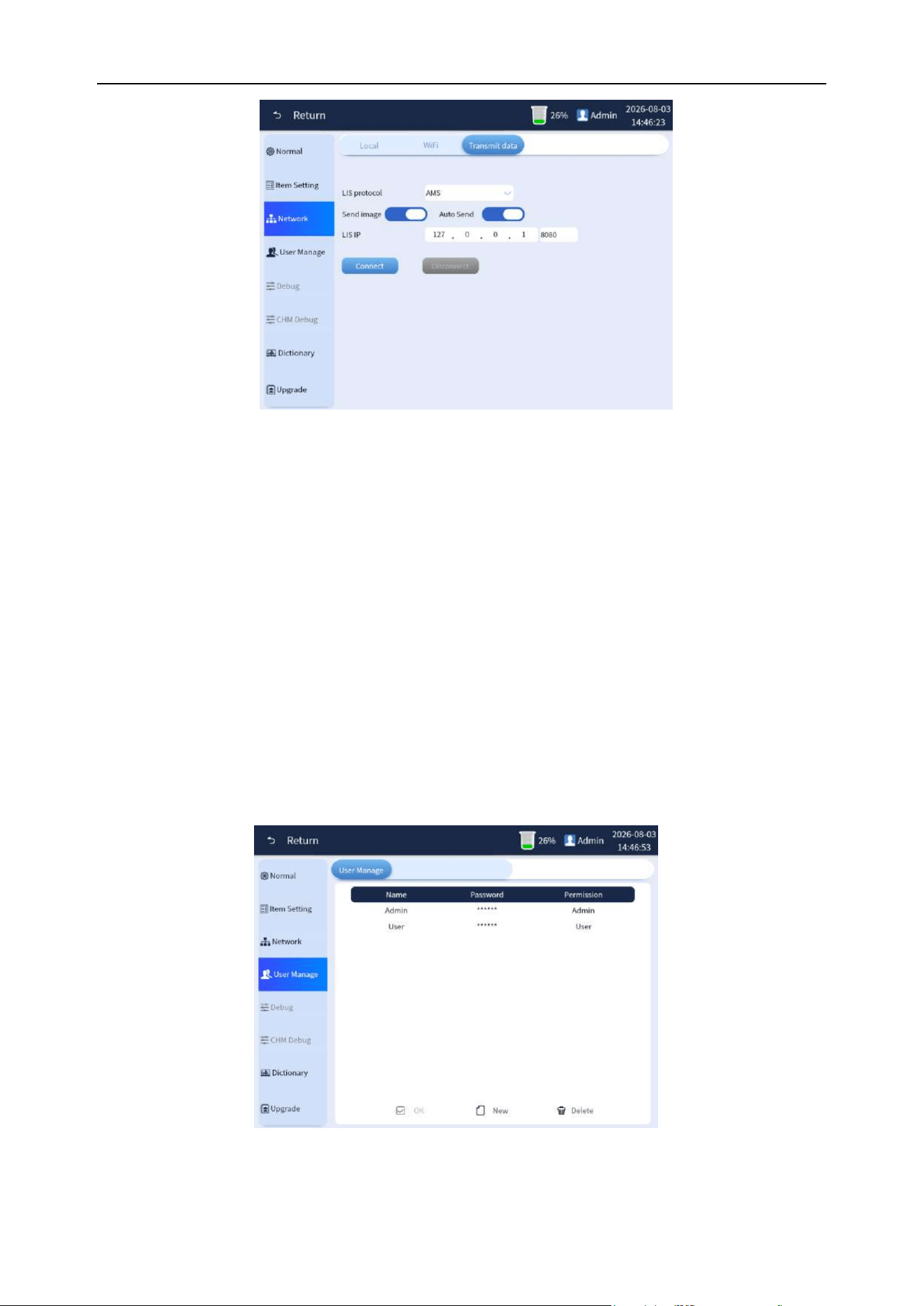
Chapter 5 Analyzer Setting
42
Figure 5-6-2 LIS connection
(1) LIS protocol:Select the protocol used for LIS communication.
(2) Send image:Set whether to send image data in LIS connection.
(3) Auto send:Set whether image data is sent immediately at the end of the test or quality control
test in LIS connection.
(4) LIS IP:Set the IP address of the LIS connected analyzer.
(5) Connect: Connect to LIS.
(6) Disconnect: Disconnect the LIS connection
5.5 User management
Overview: User management mainly manages user information, including adding users, modifying
usernames and passwords, and changing permissions. The interface is shown in Figure 5-7.
Figure 5-7 User management
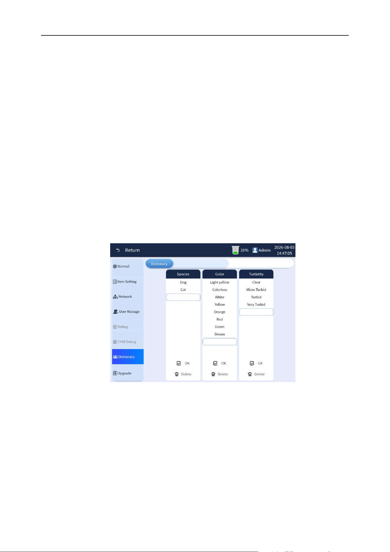
Chapter 5 Analyzer Setting
43
1) Add user: Users can be added under the Admin user login mode. Click [New] button and fill
in the username and password in the blank line of the user list. In principle, you can only add
users with User privileges. After filling in successfully, press the Enter key, the [OK] button
will turn from gray to bright, and click the [OK] button to complete the adding user operation.
2) Delete user: Users can be deleted under Admin user login mode. Select the username
directly in the user list row, the [Delete] button will turn from gray to light and click the [Delete]
button to complete the operation of deleting user.
5.6 Dictionary maintenance
Overview: It is used to set the options of sample type, color, turbidity and collection methods in the
entry of animal information. After setting, you can select the desired item through the drop-down
selection box or enter the shortcut code and press Enter to directly display it, improving the efficiency
of inputting animal data. The interface as shown in Figure 5-8.
Figure 5-8 Dictionary maintenance
You can edit and modify directly in the list, and click [Delete] to clear the row, and input the content in
the last row to add. Click [OK] to take effect.
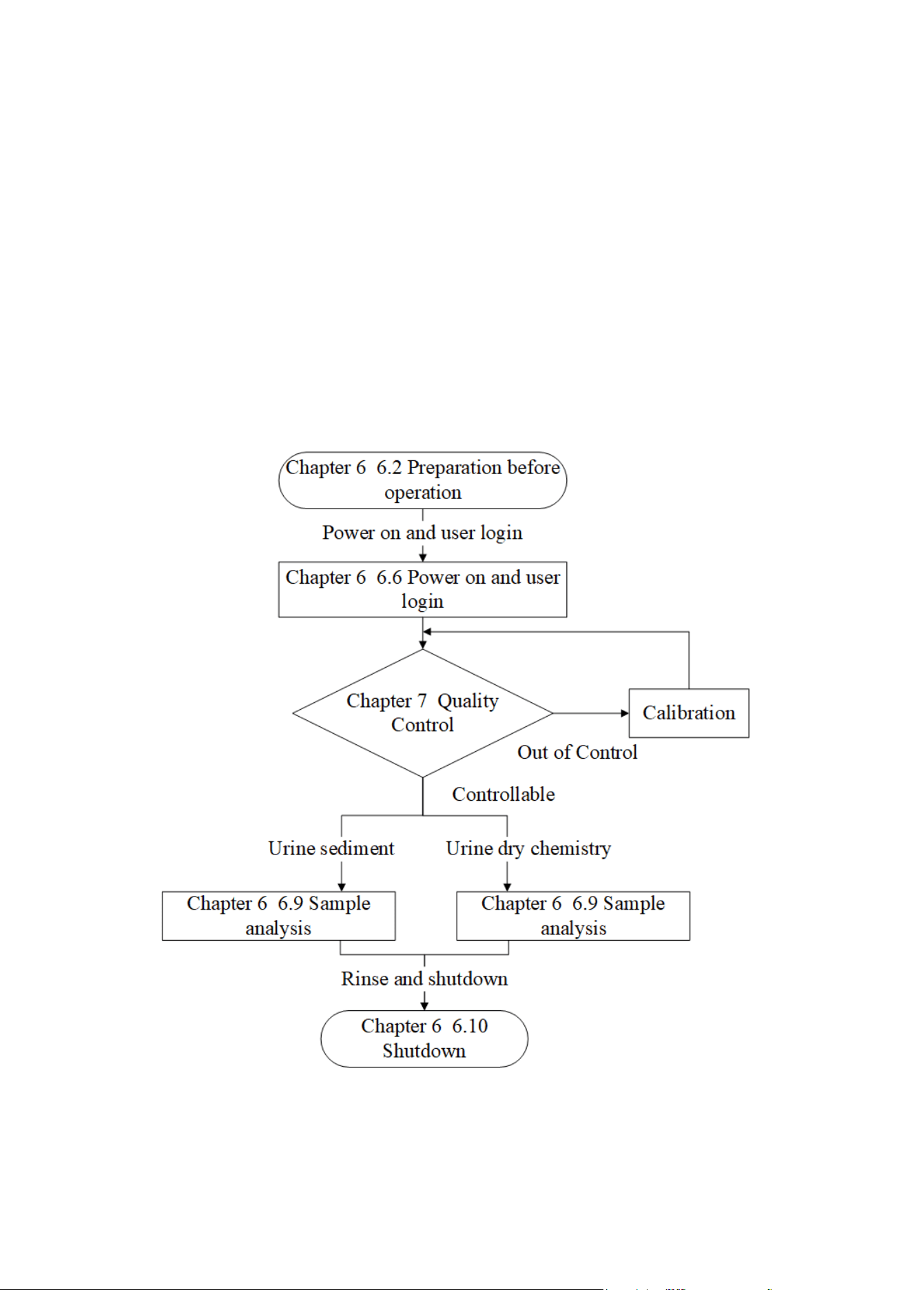
44
Chapter 6 Analyzer Operation
6.1 Overview
This chapter introduces the entire daily operation process of the analyzer from opening to closing,
focusing on the detailed description of sample analysis.
The following flowchart roughly shows the operation of this analyzer.
On the basis of grasping the overall process, please refer to the detailed description of each
operation. As shown in Figure 6-1:
Figure 6-1 Daily operation process

Chapter 6 Analyzer Operation
45
6.2 Preparation before operation
Before turning on the power of each module of the analyzer, the operator must check according to the
following requirements to ensure that the operator, samples, and system modules are ready.
Note
⚫ Biological hazards, please wear protective gloves to prevent bacterial infection.
⚫ When discarding used gloves, they must be disposed of in accordance with local
laws and regulations.
⚫ Please pay attention to prevent the urine sample from sticking to the body or directly
contact with the human body during operation to prevent bacterial infection.
⚫ The analyzer should avoid prolonged exposure to excessive humidity and high
temperature. It should be installed in a room of a suitable size, preferably one with air
conditioning, temperature and humidity
⚫ That meet the technical requirements of the analyzer. In order to ensure the accuracy
of the test results, please keep the temperature and humidity of the work room
consistent with the environmental conditions required by the urine test strip used.
⚫ If the use environment of the analyzer cannot meet the requirements specified by the
urine test strips used, the accuracy of the test results cannot be guaranteed.
6.3 Precautions
⚫ If you find an abnormal situation, please turn off the power immediately to avoid damage to
the analyzer and cause a short circuit in the power supply.
⚫ If the analyzer fails, please contact BIONOTE. Do not try to repair the analyzer by yourself,
and any repairs may damage the analyzer.
⚫ Do not place the bottle or jar with liquid on top of the analyzer, so as not to tip over and
cause the liquid to penetrate and damage the analyzer.
⚫ After completing one day's test, daily routine maintenance must be carried out to keep the
analyzer in the best status.

Chapter 6 Analyzer Operation
46
6.4 Check before starting
6.4.1 Check host space
(1) Check the space in front of the front door of the chemistry inspection port to ensure that the
chemistry test operation is not affected.
(2) Check the reagent replacement space on the left door of the host to ensure that it does not affect
the reagent replacement operation.
6.4.2 Check waste liquid container
The operator must check the waste liquid container before starting the analyzer to ensure that it has
been emptied or has sufficient capacity before starting the analyzer every day.
6.4.3 Check consumables
Make sure there is enough detergent in the built-in reagent. If not, please replace it with a new one.
For replacement operation, please refer to Chapter 3, Section 3.6.
6.4.4 Prepare test strips
Prepare the test paper type required for the test.
Note
⚫ When taking the test strip, try not to touch the test block on the test paper.
⚫ Tighten the bottle cap of the test paper tube after taking the test strip to prevent the
test paper in the tube from getting wet.
6.4.5 Check the printer (optional)
Check whether the printing paper is sufficient, whether the installation is in place, and whether the
printer power and cables are connected.
6.4.6 Check the liquid pipeline and power supply
◼ Check whether the reagent and waste liquid pipelines are bent or damaged, and whether the
connections are firm.
◼ Check whether the power plug of the analysis system is safely inserted into the power socket.
◼ Check the connection of pipelines and cables.
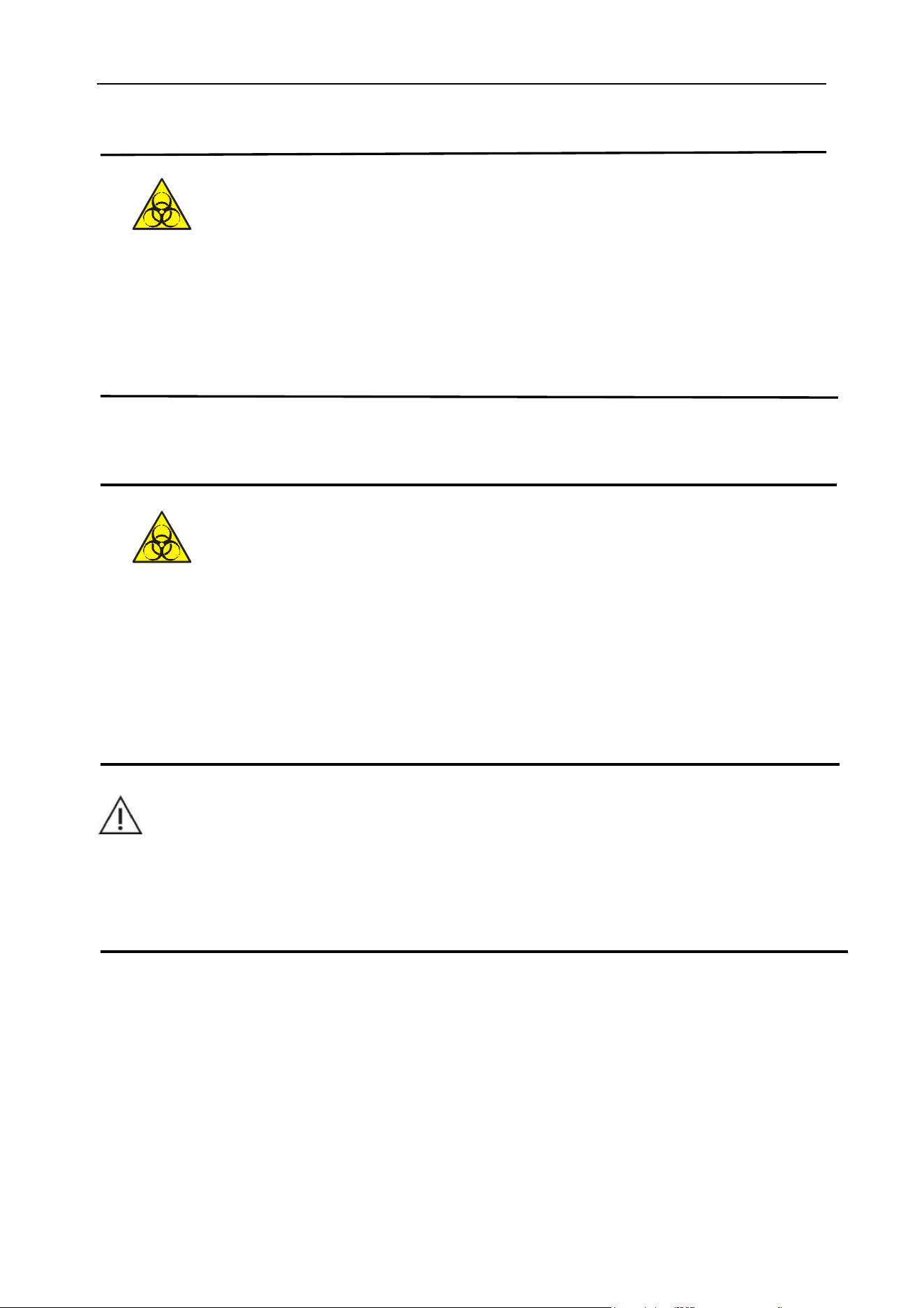
Chapter 6 Analyzer Operation
47
⚫ When the liquid pipeline is damaged, to prevent possible biological pollution leakage,
please contact the company's after-sales service department or local agent, and the
company's after-sales service department or the local agent will provide the parts and
complete the replacement.
6.5 Samples collection and handling
⚫ All objects (samples, control materials, calibrators, reagents, waste liquid, etc.), as
well as areas in contact with these substances have potentially biological infectious
hazard. Operators should abide by laboratory safety operation regulations and wear
personal protective equipment (such as protective clothing, gloves, etc.) when
touching related objects and areas in the laboratory.
WARNING
⚫ Please do not directly touch the urine sample.
⚫ Do not reuse disposable products.
Before the test, sample collection and handling need to pay attention to the following:
(1) The urine sample can be properly stirred before the test, but the sample cannot be
centrifuged.
(2) Collect fresh urine in a clean and dry container to test it as soon as possible. The urine
sample should not be placed at room temperature for more than 1 hour. Otherwise, the urine
sample should be stored in a refrigerator at 2°C to 8°C and tested within 2 hours.
Chapter 6 Analyzer Operation
48
(3) Do not disinfect or add detergent to urine samples, and do not add preservatives to urine
samples.
(4) Avoid exposure of the sample to sunlight.
(5) Injecting or taking vitamin C can cause low test results for nitrite, bilirubin, glucose, and
occult blood or even false negatives.
(6) Avoid using hematuria samples for testing. Dirt will stick and cause incorrect test results.
Direct visual inspection of hematuria color will be different from the results of the analyzer
test.
(7) The test results of urine samples collected after taking the medicine may be inaccurate.
(8) The sample size for the test is not less than 0.6mL (sediment test). If the sample size is
insufficient, the test results will be inaccurate.
6.6 Power on and user login
6.6.1 Power on
(1) Turn the power switch on the upper left side behind the host to "ON" and the power switch
will be on.
(2) Press and hold the front power standby touch button for about 3 seconds. When you hear
the sound of "drop", you can release it. The analyzer starts to enter the loading interface and
run the self-inspection program. Please wait for the self-inspection to be completed. As
shown in Figure 6-2 below:
Figure 6-2 Loading interface
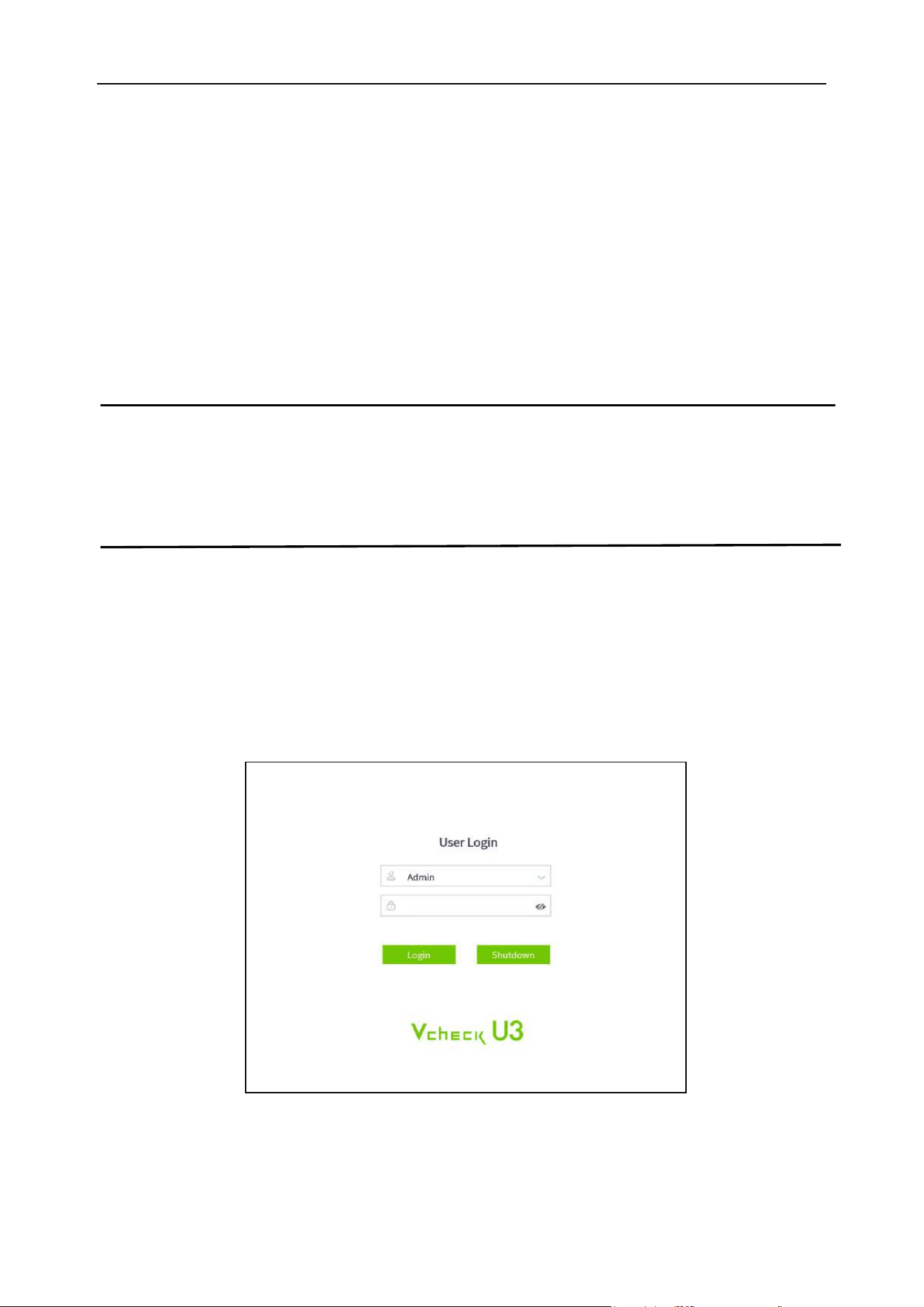
Chapter 6 Analyzer Operation
49
6.6.2 Execution of analysis system self-inspection
When the analyzer is turned on, the system will automatically execute the self-inspection program for
about 3 minutes. The self-inspection consists of the following tasks.
(1) Run the self-inspection of the software and initialize the configuration parameters;
(2) Each moving mechanism/part is restored to its initial position, and the self-inspection of the
microscope shooting system is carried out.
(3) The system automatically primes and cleans to ensure the safety of the liquid system.
(4) The system automatically performs auto focusing.
Note
⚫ The self-inspection of the system will take some time to complete. Please be patient.
⚫ Self-inspection time depends on the last analyzer status.
6.6.3 Log in to the “Admin” account
The analyzer will enter the login interface after self-inspection. Please enter the account number and
password to login to the system (For an administrator, log in to the Admin account. For a common
User, log in to the User account. The initial password is the same as the lowercase of the account
name. Please change the password after login). As shown in Figure 6-3 below:
Figure 6-3 Login interface
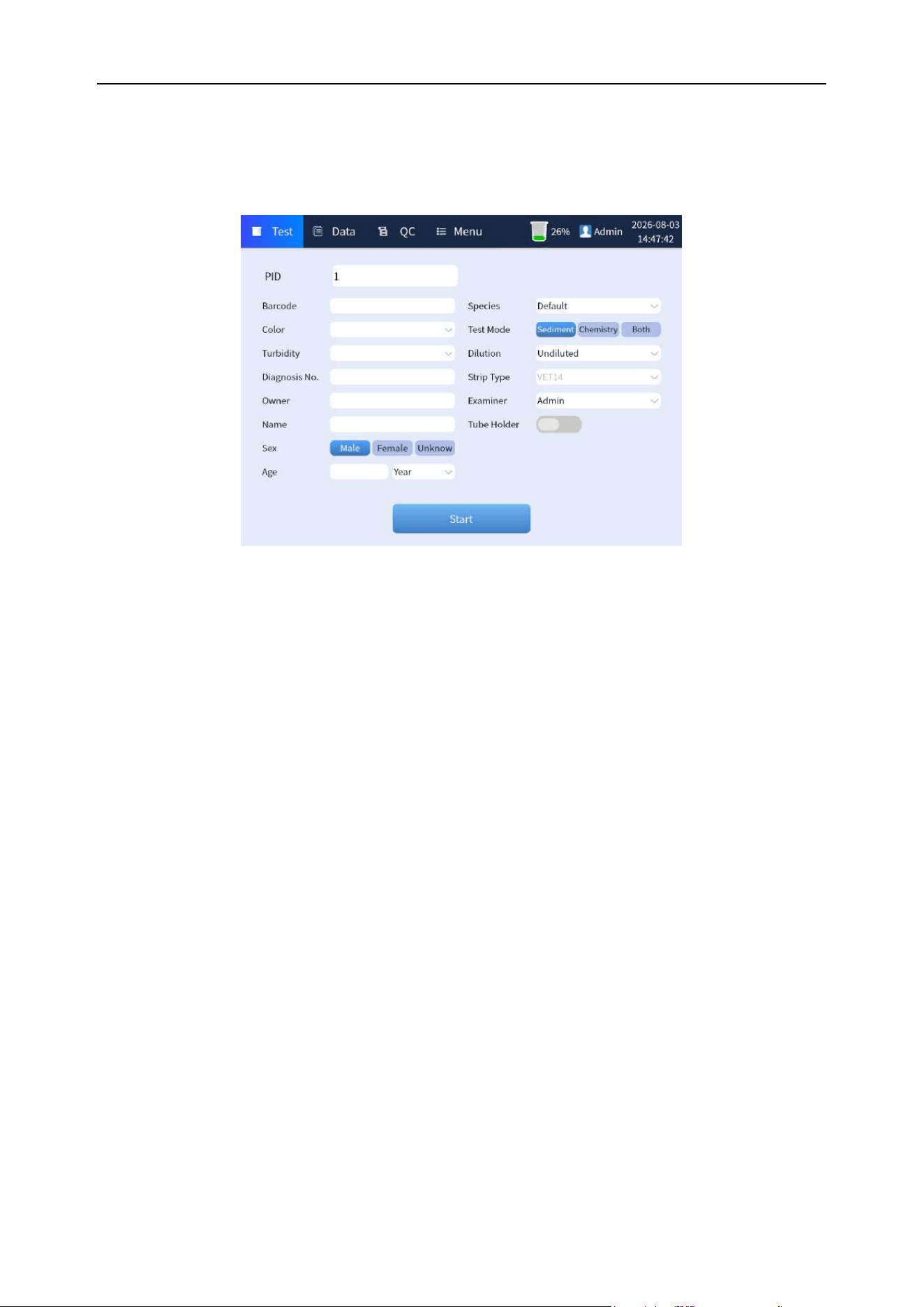
Chapter 6 Analyzer Operation
50
6.6.4 Standby test interface
Enter the correct username and password to enter the standby test interface of the system. As shown
in Figure 6-4 below:
Figure 6-4 Standby test interface
6.7 Quality control and calibration
6.7.1 Quality control
Before sample analysis, a daily quality control analysis of the analyzer is required to ensure that the
results of subsequent tests are reliable. See "Chapter 7 Analyzer QC" for detailed operation of quality
control.
6.7.2 Calibration
When the quality control of the analyzer is out of control, the cause can be found according to the
actual situation, possibly using microscope calibration or result calibration. See “Chapter 8 Analyzer
Calibration” for specific methods of calibration.
6.8 Software interface
6.8.1 Software test interface
Overview: After the analysis system is started successfully, the normal [Test] interface is displayed,
and the buttons of [Data], [QC] and [Menu] option are displayed on the interface at the same time, as
well as information such as reagent capacity status, login user and date, as shown in Figure 6-5.
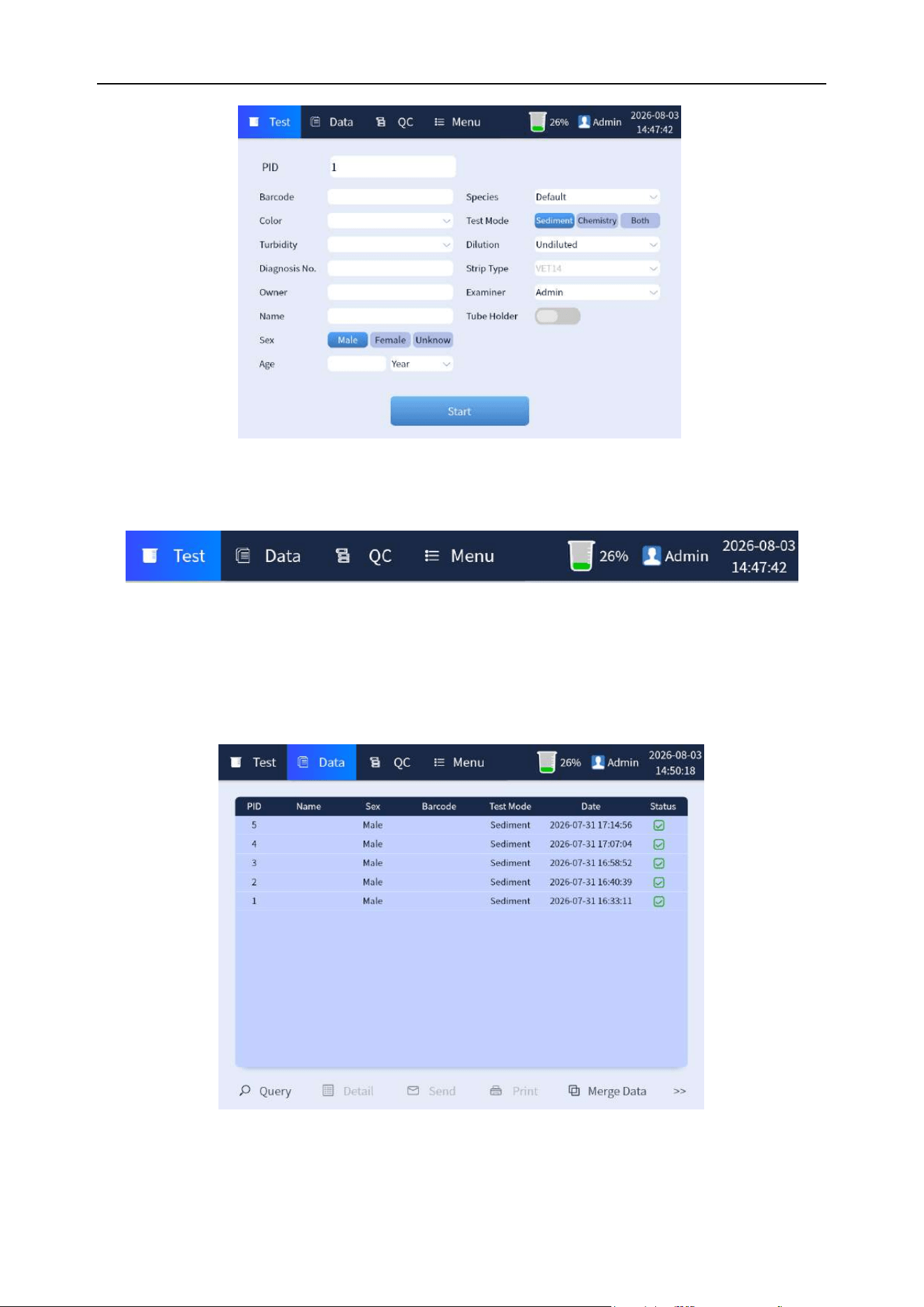
Chapter 6 Analyzer Operation
51
Figure 6-5 Software test interface
The information on the top bar of the interface is as shown in Figure 6-6 below:
Figure 6-6 Top bar display of test interface
6.8.2 Data interface
Click the [Data] button to enter the data view interface where you can query the data of each report
with the tests completed, and can print, send or export, and delete test results.
Figure 6-7 Data interface
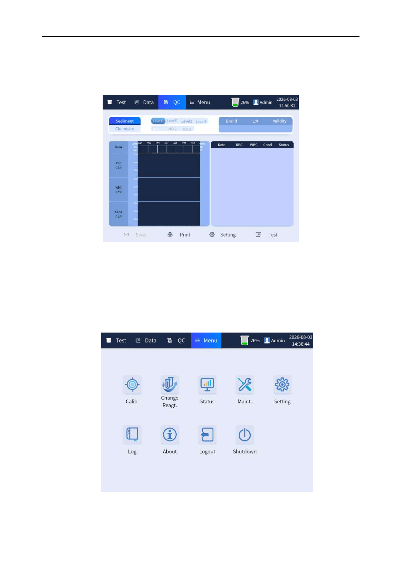
Chapter 6 Analyzer Operation
52
6.8.3 Quality control interface
Click the [QC] button to enter the quality control interface to manage setup and test the chemistry and
urinary sediment quality control.
Figure 6-8 Quality control interface
6.8.4 Menu interface
Click the [Menu] button to enter the menu interface, which includes [Calib.], [Change Reagt.], [Status],
[Maint.], [Setting], [Log], [About], [Logout] and [Shutdown]. Select each function button to perform
corresponding operations on the analyzer. As shown in Figure 6-9:
Figure 6-9 Menu interface
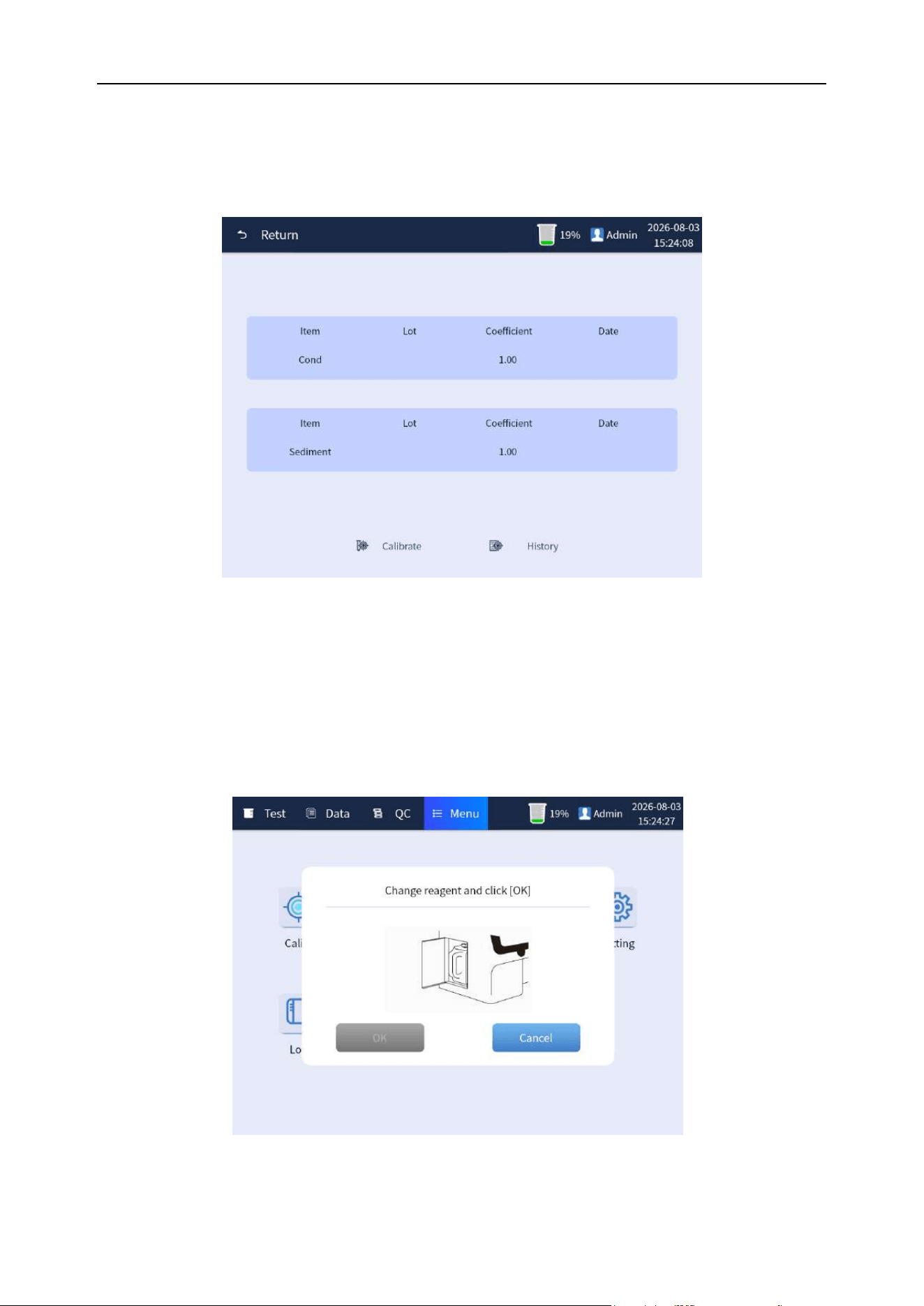
Chapter 6 Analyzer Operation
53
6.8.4.1 Calibration
Click the [Calib.] button to enter the calibration interface to conduct calibration test and adjustment of
[Cond] and [Urine sediment], as well as query of calibration history. As shown in Figure 6-10:
Figure 6-10 Calibration interface
6.8.4.2 Replacing reagents
Click the [Change Reagt.] button to enter the interface of replacing reagents. Perform this operation
when the detergent in the built-in reagents needs to be replaced after use or is installed for the first
time, as shown in Figure 6-11. Please refer to "Chapter 4 Analyzer Installation 4.6" for detailed
operation.
Figure 6-11 Replacing reagents interface
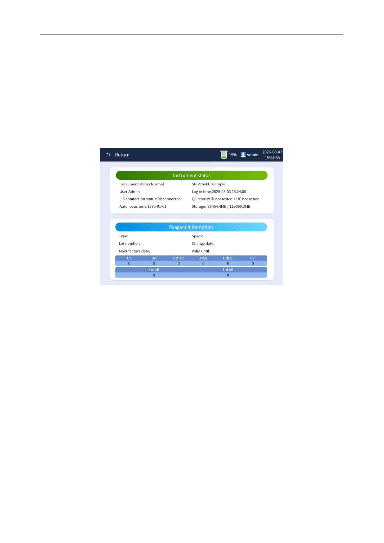
Chapter 6 Analyzer Operation
54
6.8.4.3 Status
Click the [Status] button to enter the status interface, which displays the analyzer status list and
reagent information list. As shown in Figure 6-12:
(1) Instrument status list mainly displays; analyzer status, user information, quality control
status and LIS connection status, etc.
(2) The reagent status list mainly displays: the type, specification, batch No. and date of
manufacture, etc. of reagents.
Figure 6-12 Status interface
6.8.4.4 Maintenance
Click the [Maint.] button to enter the replacement and maintenance interface, which can perform the
operations of [Rinse], [Soak], [Clean Strip Holder], [Empty], [Prime] and [Focus]. Please refer to
relevant chapter of “Chapter 9 Analyzer Maintenance” for detailed operation. As shown in Figure 6-13:
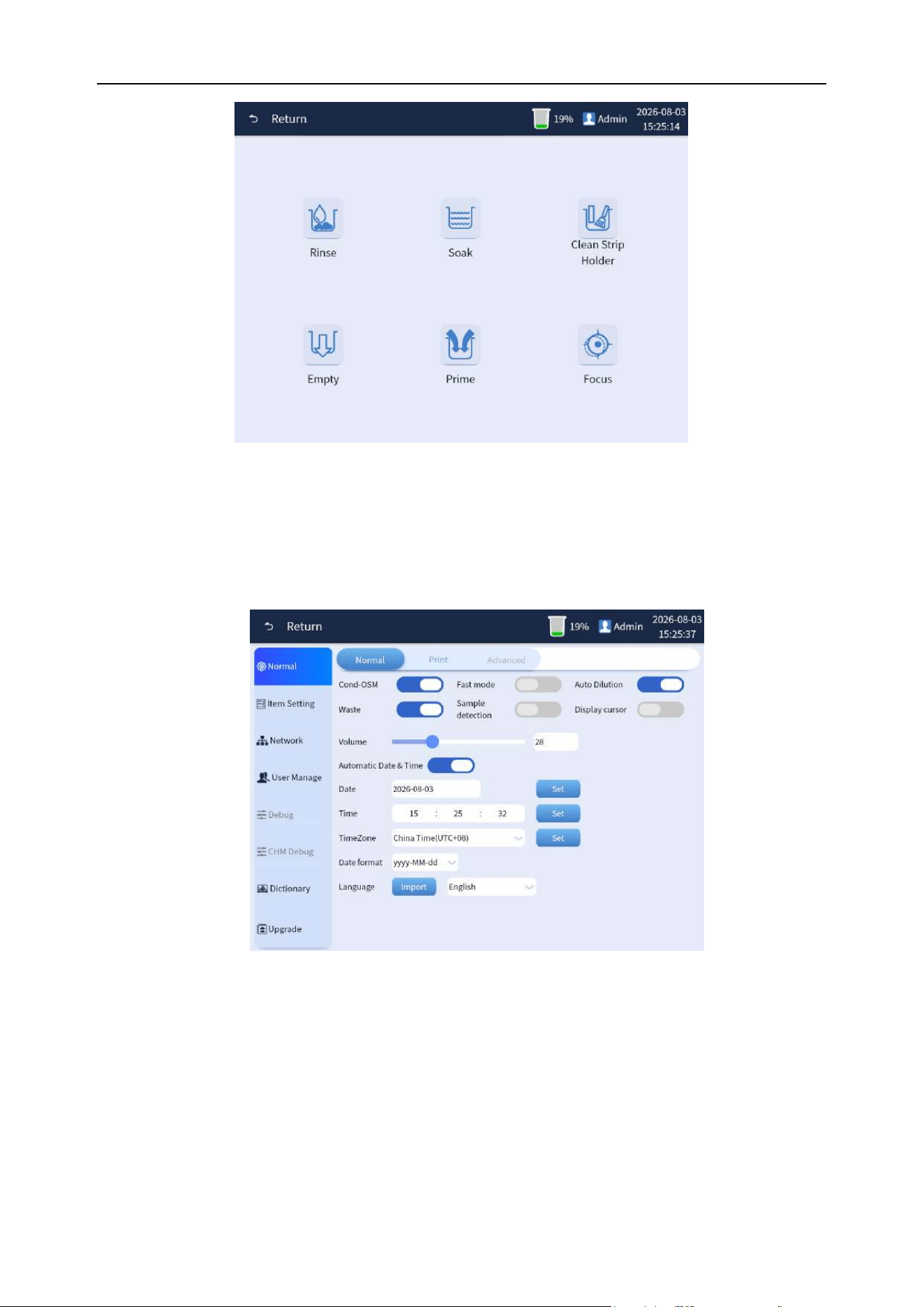
Chapter 6 Analyzer Operation
55
Figure 6-13 Maintenance interface
6.8.4.5 Settings
Click the [Setting] button to enter the setting interface. Please refer to "Chapter 5 Analyzer Settings"
for detailed operation. As shown in Figure 6-14:
Figure 6-14 Setting interface
6.8.4.6 Log
Click the [Log] button to enter the log interface where the log information of the analyzer system can
be queried by entering date. And log information can be uploaded or exported, as shown in Figure
6-15:
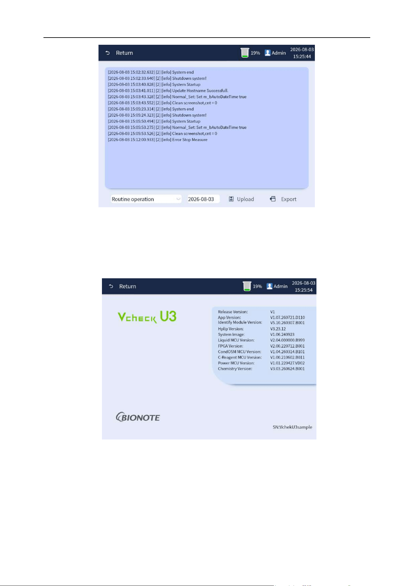
Chapter 6 Analyzer Operation
56
Figure 6-15 Log interface
6.8.4.7 About
Click [About] to display information about each program version of the current analyzer, as shown in
Figure 6-16:
Figure 6-16 About interface
6.9 Sample analysis
6.9.1 Daily test interface
Overview: In the main interface of the daily test interface, fill in the starting sample ID and test type,
etc. The test interface is shown in Figure 6-17 below:
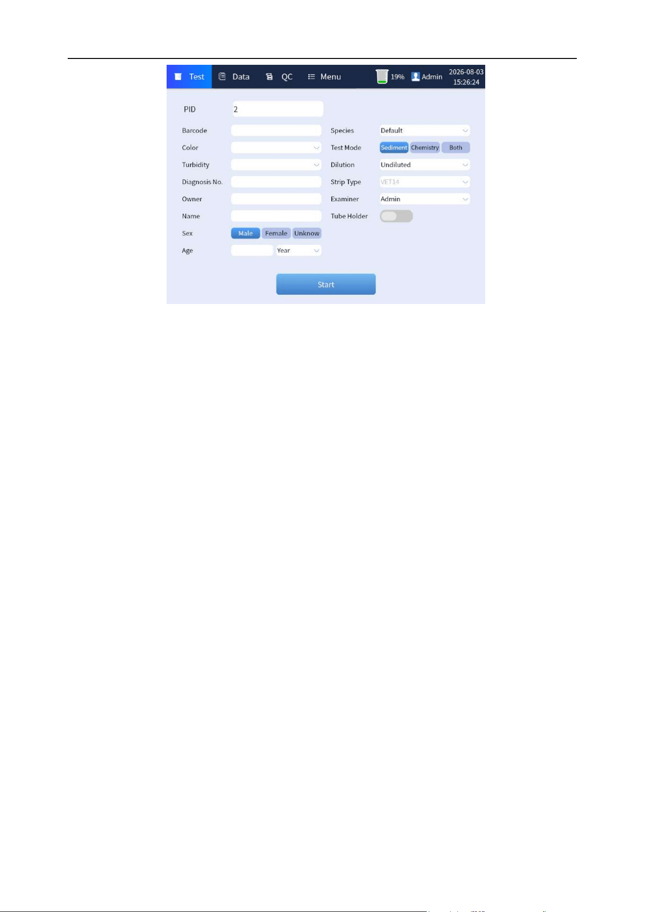
Chapter 6 Analyzer Operation
57
Figure 6-17 Daily test display interface
1) PID: Click the corresponding blank bar to enter the current sample ID information.
2) Barcode: Click the corresponding blank bar to enter the current sample barcode information.
3) Diagnosis No.:Click the corresponding blank bar to enter the Diagnosis No. information.
4) Owner: Click the corresponding blank bar to enter the Owner name.
5) Name: Click the corresponding blank bar to enter the pet's name.
6) Sex: Select the pet's gender by clicking the drop-down menu.
7) Age:Click the corresponding blank bar to enter the age. Click the drop-down menu to select
the age unit.
8) Species:Click on the drop-down menu to select the animal type.
9) Mode: According to the test requirements, select a single chemistry test or a urine sediment
test, or join by clicking the drop-down menu.
10) Dilution Rate:Select dilution rate by clicking the drop-down menu.
11) Strip type: Select the type of test strips of corresponding test by clicking the drop-down
menu. (This parameter is optional only when the test mode is chemistry or Joint)
12) Examiner: Select doctor for testing by clicking the drop-down menu.
13) Tube holder: Whether to use a test tube holder to place the sample of urine sediment test.
14) Start: Click this button for a normal testing process.
6.9.2 Start testing
6.9.2.1 Urine sediment test
Step 1: In the daily test interface, fill in the ID number and animal information in the corresponding
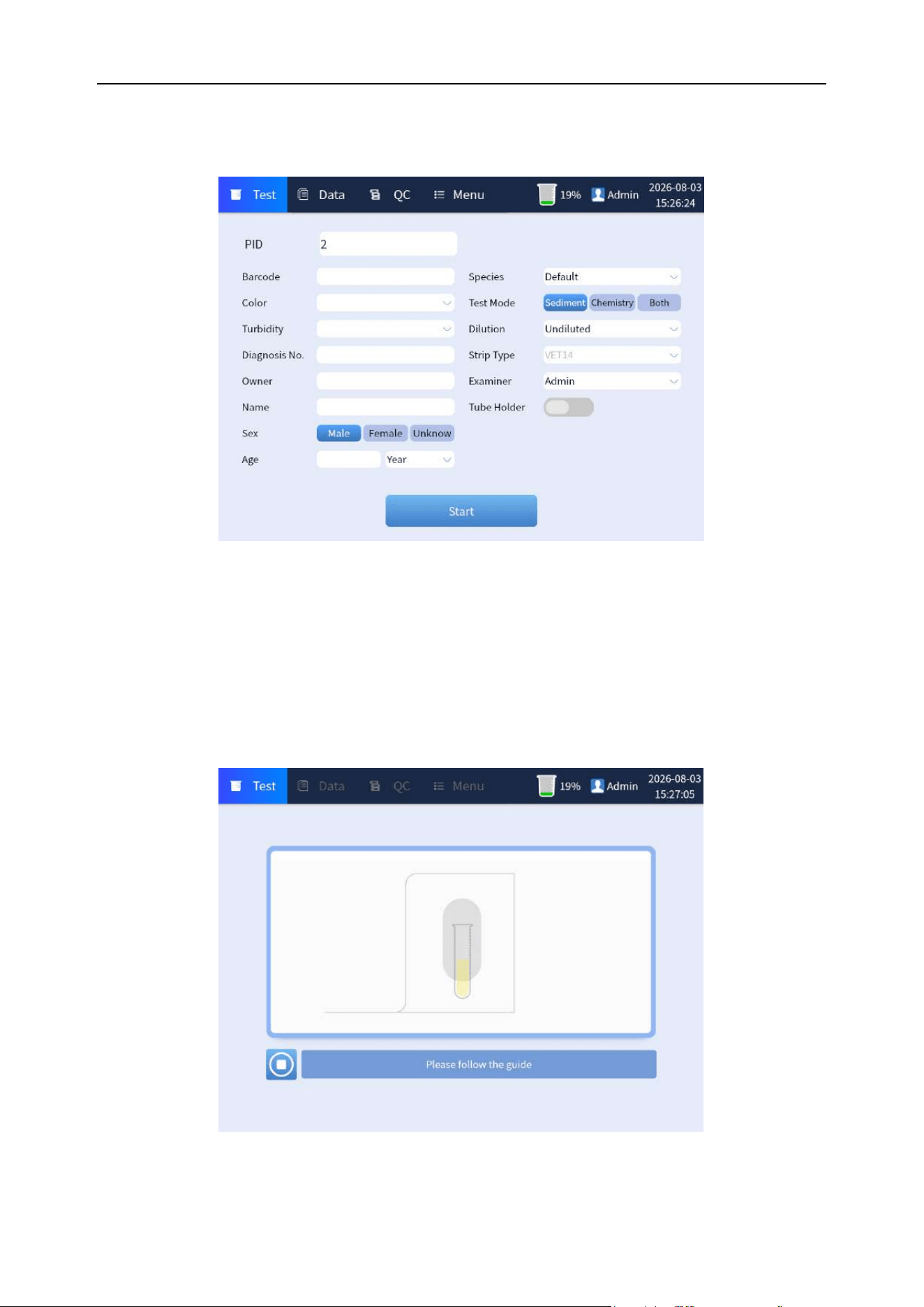
Chapter 6 Analyzer Operation
58
edit box, and select the information of doctor for testing in the select box, and then select "Urine
sediment" in [Mode] to enter the urine sediment test. As shown in Figure 6-18 below:
Figure 6-18 Test type selection
Step 2: Click the [Start] button to enter the test prompt animation interface. Shake the sample for 5
seconds as prompted or directly press the suction mechanical button of the host to complete the
sample suction, and the test progress bar window will pop up. As shown in Figure 6-19 and 6-20-1;
If the samples is in high concentration, the analyzer will dilute the sample and retest it. As shown in
Figure 6-20-2.
Figure 6-19 Daily test display interface
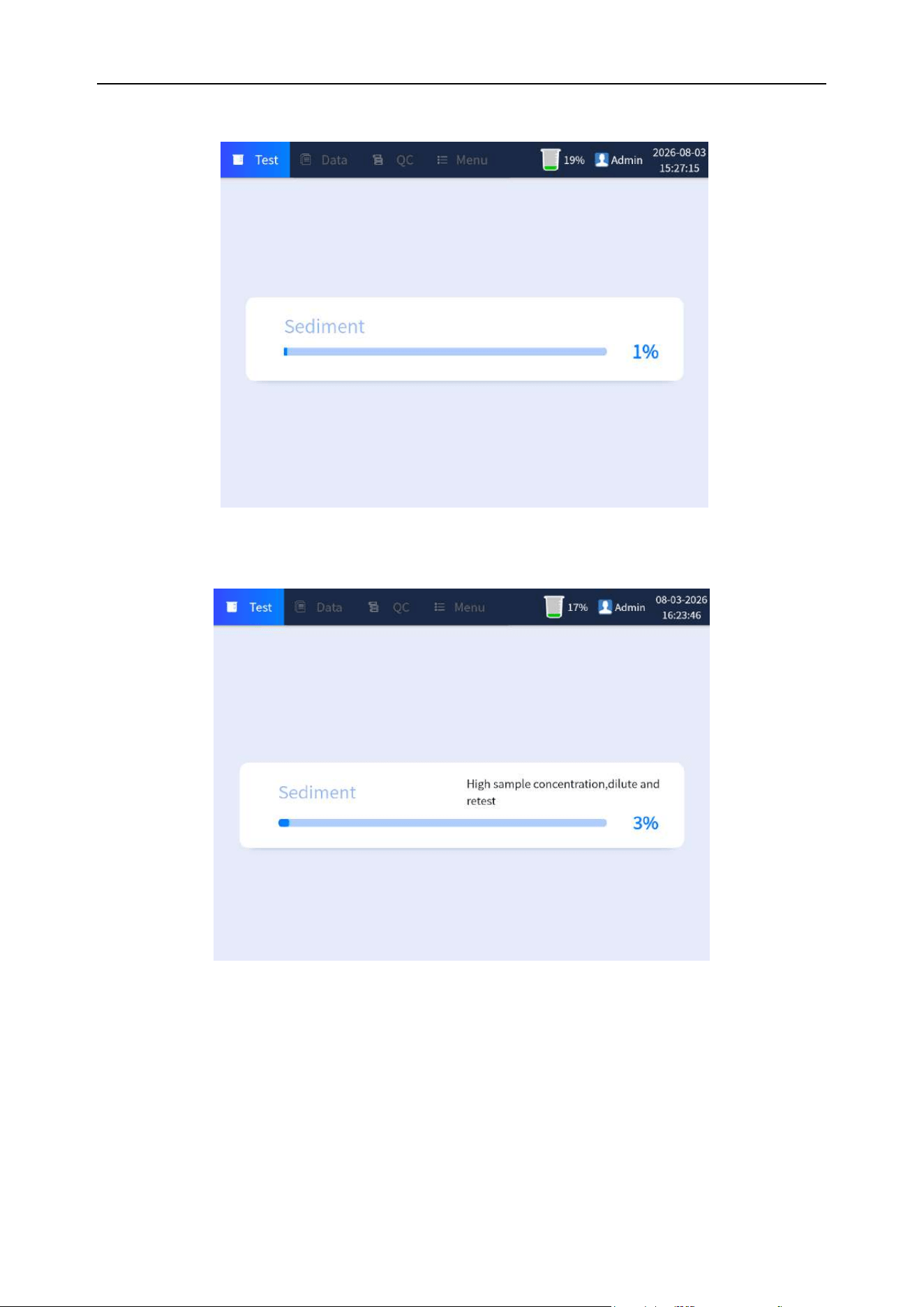
Chapter 6 Analyzer Operation
59
Figure 6-20-1 Test progress display interface
Figure 6-20-2 Test progress display interface of high concentration sample
Step 3: The interface is as follows the test. If there is no objection to the test results, click [Save] to
save the test results. For manual review, click [Image] to enter manual review. Please refer to "6.9.3"
in this chapter for details.
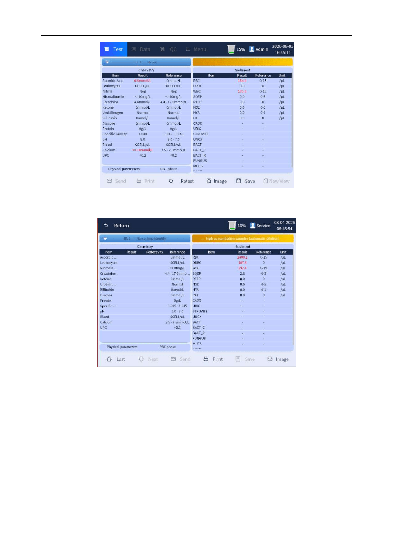
Chapter 6 Analyzer Operation
60
Figure 6-21-1 Test results display interface
Figure 6-21-2 Test results display interface after Diluted
6.9.2.2 Urine chemistry test
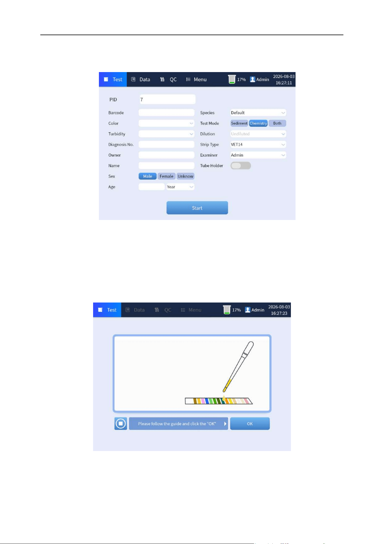
Chapter 6 Analyzer Operation
61
Step 1: In the main interface of the daily test interface, fill in the information about animals and doctor
for testing, and select "Chemistry" in [Mode] item to enter the chemistry test. As shown in Figure 6-22
below:
Figure 6-22 Test type selection
Step 2: Click the "Start" button to enter the test prompt animation interface. Please follow the prompts
to complete the test strips dripping or dipping operation, and correctly place the test strips. Click the
[OK] button to complete the operation, and the test progress bar window will pop up. As shown in
Figure 6-23 and 6-24:
Figure 6-23 Test type selection
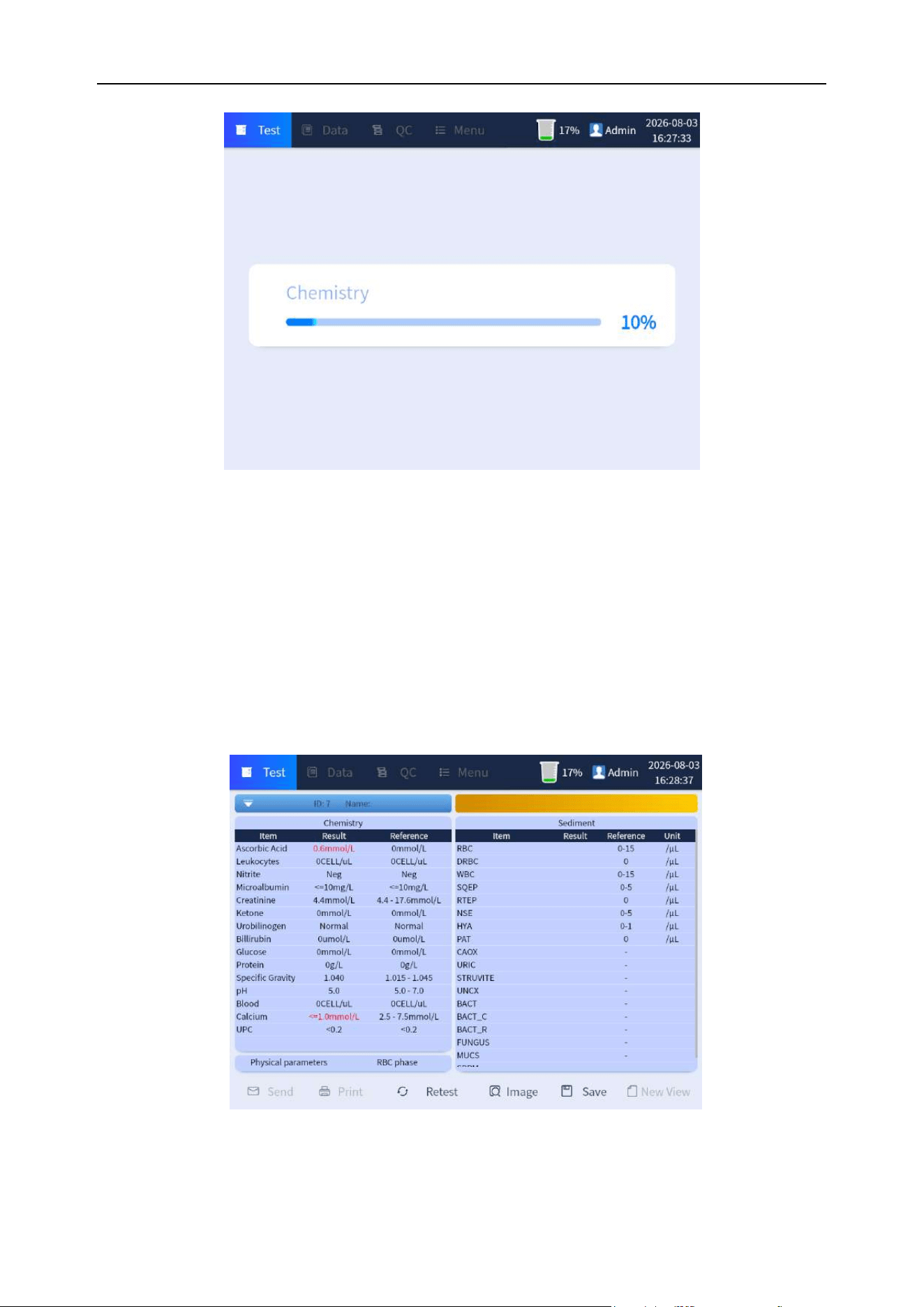
Chapter 6 Analyzer Operation
62
Figure 6-24 Test progress display interface
Step 3: Click [Save] at the bottom of the display interface to save the test results after the test. As
shown in Figure 6-25 below:
Figure 6-25 Chemistry test result display interface
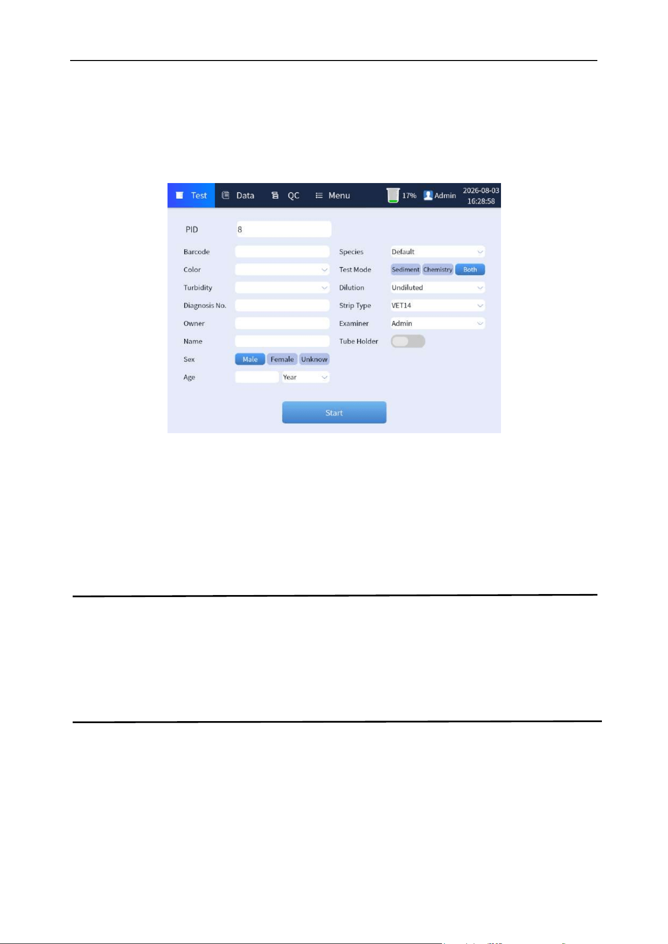
Chapter 6 Analyzer Operation
63
6.9.2.3 Urine chemistry + urine sediment test
Step 1: In the main interface of the daily test interface, fill in the information about the animal and
doctor for testing, and select "Both" in the [Mode] item, and select the test strip type according to the
test requirements, then enter the mixed test mode. As shown in Figure 6-26 below:
Figure 6-26 Test type selection
Step 2: Please refer to "Section 6.9.2.1 of this Chapter" for the operation to complete the urine
sediment test.
Step 3: Please refer to “Section 6.9.2.2 of this Chapter” for the operation to complete the urine
chemistry test.
Note
⚫ The chemistry test paper inlet will have a test bracket outstretch. Please pay attention to
reserve space (at least 12 cm), and do not block the door to prevent the analyzer from
working abnormally or even being damaged.
6.9.3 Display interface after the test
Upon completion of the test is displaying the results that containing the chemistry analysis results,
urine sediment analysis results, and the Physical parameters and RBC morphology parameters, and
there are buttons of [New View], [Save], [Print], [Send], [Retest], and [Image] in the lower bar of the
interface, as shown in the Figure 6-27:
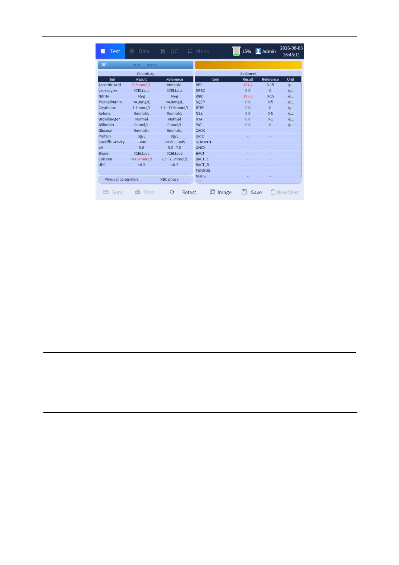
Chapter 6 Analyzer Operation
64
Figure 6-27 Display interface after the test
(1) Send: Send all selected samples to LIS.
(2) Print: Print/print preview the selected sample results.
(3) Retest: According to test requirements, click to enter the retest interface.
(4) Image: Click the [Image] button to enter the manual classification of sediment analysis, as shown
in Figure 6-28.
(5) Save: Save review results after manual review.
(6) New View: Click the [New view] button to enter the interface to be tested. See "Section 6.9.2" for
related operations.
Note
⚫ Operations such as printing and sending can be performed only when clicking the
[Save] button.
6.9.3.1 Manual classification of sediment analysis
Mainly used for manual review to confirm test results. By reviewing the program, you can review,
analyze and confirm the sediment analysis results of the analyzer.
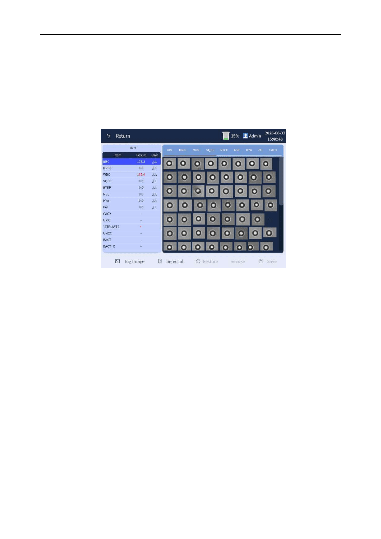
Chapter 6 Analyzer Operation
65
The classification interface is shown in Figure 6-28. In the Figure, the "RBC" of deepened blue on the
bottom of the left bar is the small picture indicating the type of the item currently displayed. The next
"524.8/uL" indicates the current result of the item. Click different bars to switch items. View the
displayed small picture in the right area. If there are particles that do not match, "click" the
corresponding items on the upper right side (marked with blue shading), and then "click" the
operation in the display small picture to the selected correct items until all the particles in the item are
correct.
Figure 6-28 Manual classification
(1) Return: Return to the previous menu.
(2) Big image: Switch to view between original graph and particle graph.
(3) Select all:Select all images that are currently displayed unclassified.
(4) Restore: Cancel the manual classification results and restore the result classification.
(5) Revoke:Undo all unsaved operations.
(6) Save: Save the review results after manual review.
The specific steps of classification are as follows:
Step 1: Classification to "WBC": Click the item on the left to select the item to be reviewed, and its
small picture of cell is displayed in the right area. Select the small picture of cell to be classified, as
shown in Figure 6-29:
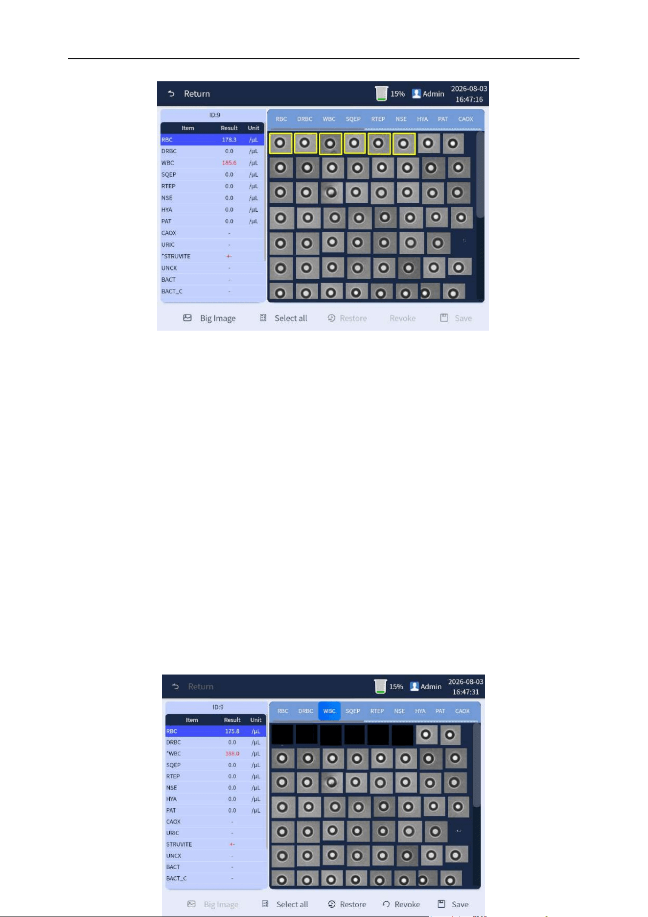
Chapter 6 Analyzer Operation
66
Figure 6-29 Review and selection of item
Step 2: Click the cell that is considered "WBC". Click "WBC" item in the upper bar on the right, and it
will turn into blue shading when selected. The small picture of the clicked cell is selected and
displayed on a black background, and the cell is automatically assigned to the "WBC" (click "Restore"
to undo the selection and classification). During the classification, the results of each item will be
automatically calculated and refreshed. After the classification, click [Save] to save the data, and then
click [Return] button to complete the operation. As shown in Figure 6-30:
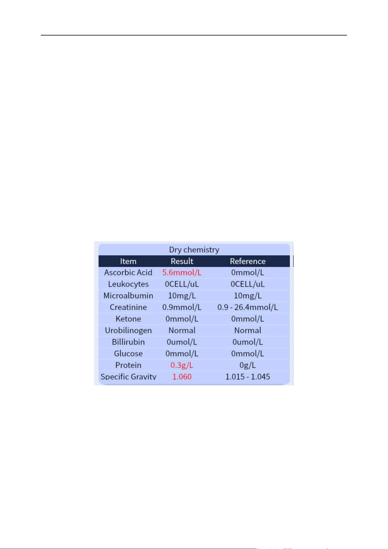
Chapter 6 Analyzer Operation
67
Figure 6-30 Classification and selection operation
6.9.3.2 Chemistry
Purpose: To display the various items of the urine dryness test, such as vitamin C, white blood cells,
ketone bodies, nitrite, urobilinogen, bilirubin, protein, glucose, urine specific gravity, occult blood, pH,
creatinine, urine calcium, microalbumin values. The items can be displayed by means of a drop-down
slide, as shown in Figure 6-31 (10 items or 11 items or 14 items are displayed according to the type of
test papers):
Figure 6-31 Chemistry test results
6.9.3.3 Physical Parameters
Purpose: Mainly used to provide inspections of science of the color, specific weight, turbidity, as well
as conductivity and osmotic pressure for urine samples, which can provide physicians with clinical
reference for diagnosis, and efficacy observation of urinary diseases. As shown in Figure 6-32:
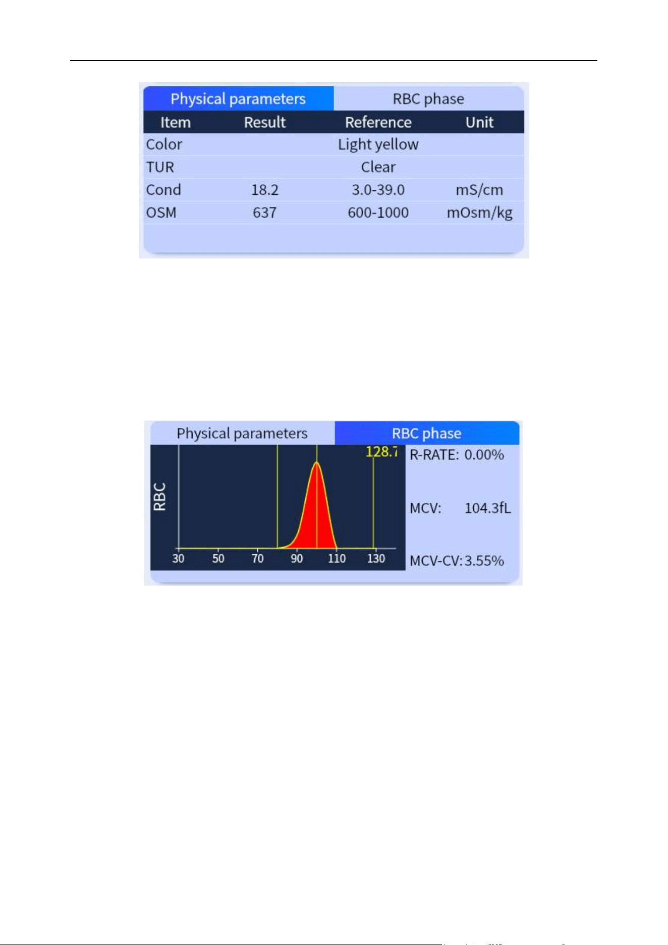
Chapter 6 Analyzer Operation
68
Figure 6-32 Display of parameters of science
6.9.3.4 Red blood cell phase
Purpose: Mainly used to provide data such as size distribution, average volume, abnormal proportion
and CV of distribution width of red blood cells, which allows the physician to judge the origin of the red
blood cells in combination with the shape of the cells. As shown in Figure 6-33.
Figure 6-33 Red blood cell phase (RBC)
Chapter 6 Analyzer Operation
69
6.10 Shutdown
WARNING
⚫ The sample probes of the analyzer are sharp and may be contaminated with
biohazardous substances. Sample probes will move in the working process of the
analyzer, so do not move close to the sample probe if they do not operate the
analyzer. When operating the analyzer, follow the correct operation method and
ensure that the operator has received sufficient training to operate the procedure in
the safest way before operating the process. Avoid getting your hands stabbed.
Note
⚫ Ensure analyzers and samplers are on standby.
⚫ If the status indicator is not green, wait until the green light is on.
⚫ Ensure that there are no test strips on the urine chemistry analysis test bracket
⚫ To ensure stability of the analyzers and accuracy of the analysis results, shutdown as
required while the analyzer has been working continuously for up to 24 hours.
⚫ It is important that the operator performs the normal shutdown procedure following
the steps below to shut down.
(1) Long press the "Power" button on the front of the analyzer, or click the [Menu] button on the
screen, and click the [Shutdown] button after switching interface, and the following dialog box will
pop up. Click the “OK” button to start performing the shutdown timing. The interface is shown in
Figure 6-34 below.
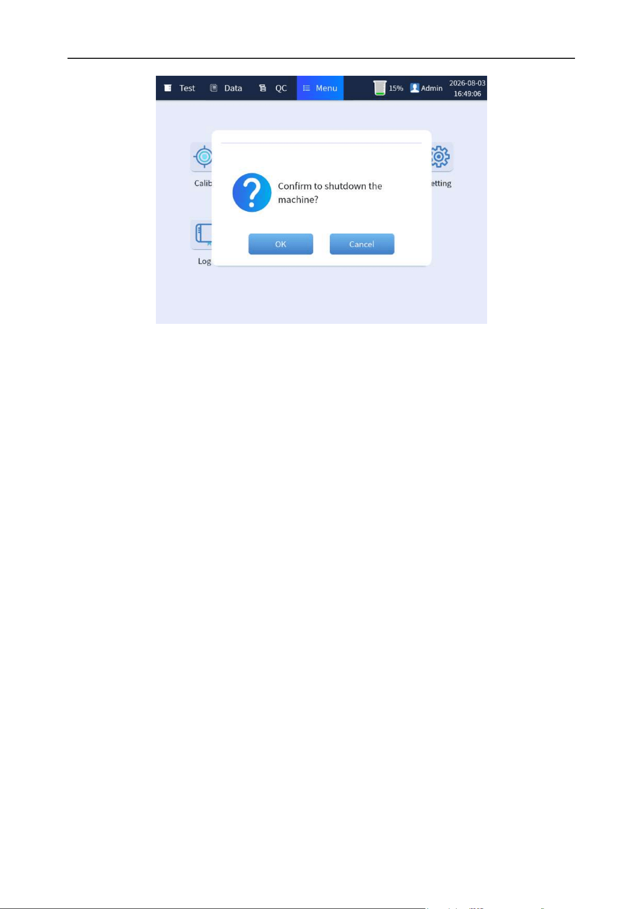
Chapter 6 Analyzer Operation
70
Figure 6-34 Shutdown interface
(2) After the shutdown, turn the power switch behind the host to the "OFF" position. Empty the waste
liquid container and dispose of the waste liquid properly.
6.11 When the analyzer stops working
(1) If there is a sudden power failure, turn off the power immediately.
(2) When the analyzer stops working because of abnormality, turn off the power first. Clean the
parts with biological risk of the analyzer and prompt the relevant personnel about the risk of
the analyzer. Then the abnormality can be judged and handled according to the chapter of
Fault Handling. If you are unable to handle it, please contact your technical service
personnel or after-sales service personnel of BIONOTE.
(3) If the analyzer needs to be carried and transported in a short distance, please perform a
series of shutdown operations first, then unplug the waste liquid pipeline and power cord of
the analyzer, and then carry and transport. During transportation, please ensure that the
analyzer is upright and stable. Do not shake the analyzer violently, or put it flat or upside
down.
(4) If long-distance transportation is required, please contact BIONOTE technical service
personnel.
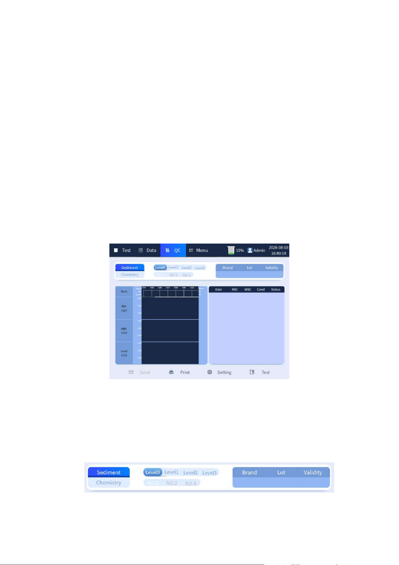
71
Chapter 7 Quality Control
7.1 Overview
Quality control is used to reflect the operation status of the analyzer. Therefore, in order to
understand the current status of the analyzer and obtain reliable test results, quality control is
required before testing samples every day. If the result is controllable, it means that the analyzer
operates normally and the result is reliable; if the result is out of control, the causes can be found from
the microscope focusing (see 8.2) and the status of quality control materials, and then the quality
control can be tested after adjustment. The sample test can be carried out only when the results are
controlled.
7.2 Quality control interface
Quality control interface. The interface is shown in Figure 7-1 below.
Figure 7-1 Quality control interface
7.2.1 Quality control selection and gear information
The information displayed on the upper part of the interface includes chemistry and sediment quality
control switch selection and corresponding quality control gear, and the right window shows the
"Brand", "Lot" and "Validity" information of current quality control. As shown in Figure 7-2-1 below:
Figure 7-2-1 Quality control selection and gear information interface
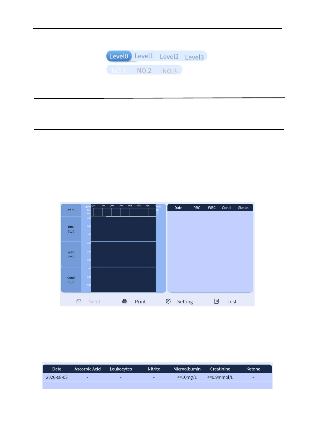
Chapter 7 Quality Control
72
Chemistry and sediment each have 3 quality control gears. As shown in Figure 7-2-2 below:
Figure 7-2-2 Quality control gear options
Note
⚫ The deep blue background means that the item is selected.
7.2.2 History quality control information of urine sediment
The left and right sides of the lower part on the quality control interface are divided into two areas.
Quality control graph area on the left: The queried data is displayed as LJ quality control graph.
Results display area on the right: The queried data results are displayed in the list by date. As shown
in Figure 7-3 below:
Figure 7-3 Urine sediment quality control data display interface
7.2.3 History quality control display information of chemistry
The queried data results of quality control are displayed in the list by date. As shown in Figure 7-4
below:
Figure 7-4 Chemistry quality control display interface
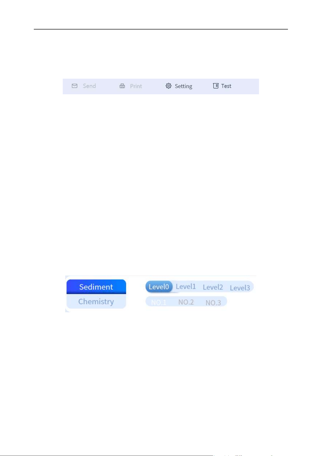
Chapter 7 Quality Control
73
7.2.4 Quality control interface button
The lower part of the quality control interface includes [Send], [Print], [Setting] and [Test] buttons. As
shown in Figure 7-5 below:
Figure 7-5 Bottom bar button of quality control interface
(1) Send: Send quality control data to LIS.
(2) Print: Print quality control test report.
(3) Setting: Set up information-related quality control, see 7.3 for details.
(4) Test: Used to test setting information quality control.
7.3 Quality control settings
7.3.1 Quality control settings and tests of sediment
7.3.1.1 Item selection
On the quality control interface, select "Sediment" and the corresponding gear (the selected items are
displayed with the dark blue bottom), as shown in Figure 7-6 below. On the quality control interface,
click [Setting] button to enter the newly created interface. As shown in Figure 7-7 below:
Figure 7-6 Item selection
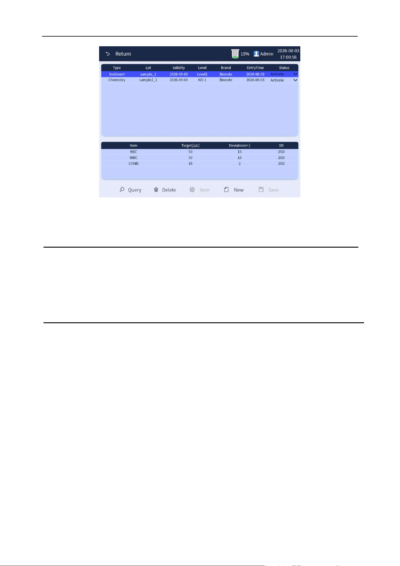
Chapter 7 Quality Control
74
Figure 7-7 Newly created interface
Note
⚫ For the setting and testing of different gears of quality control, please select different
gears in the "Item selection" step. Other settings and testing methods are the same.
⚫ Selected items are identified in dark blue background.
7.3.1.2 Data filling and saving
Click [New] button to enter the new interface. Fill in the corresponding information such as "Type",
"Lot", "Validity" and "Level" according to the quality control material information and fill in the data
input level of "Target" and "Deviation", as shown in Figure 7-8 below. Click the [Save] button after
completing the filling, and click [OK] to complete the operation, as shown in Figure 7-9 below:
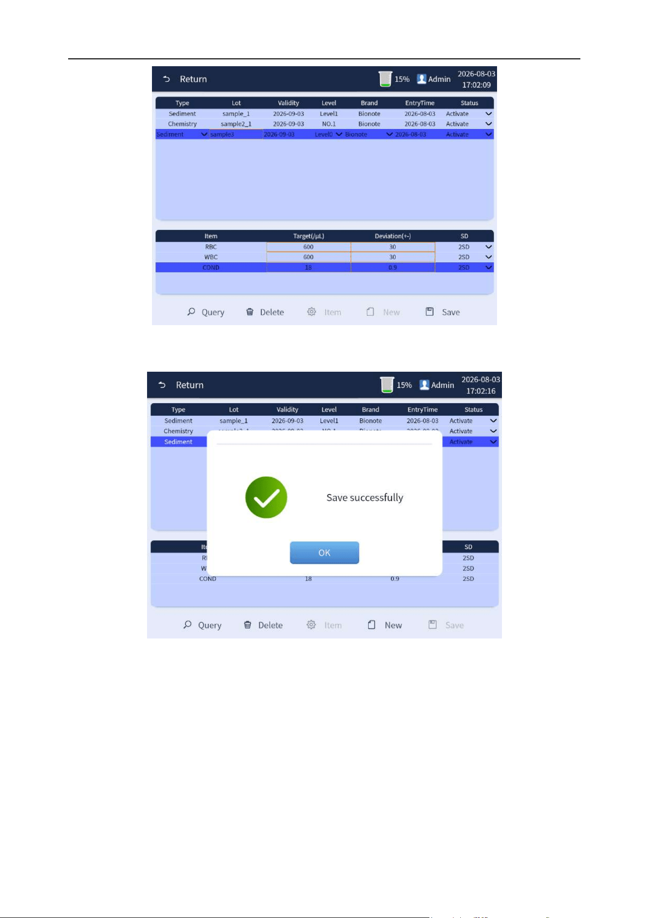
Chapter 7 Quality Control
75
Figure 7-8 Data filling of quality control items
Figure 7-9 Data saving of quality control
7.3.1.3 Quality control tests
After the quality control data is successfully saved, click the [Return] button to return to the quality
control interface, and click the [Test] button to conduct the quality control test, as shown in Figure
7-10 below. Complete the quality control test as prompted, as shown in Figure 7-11 below:
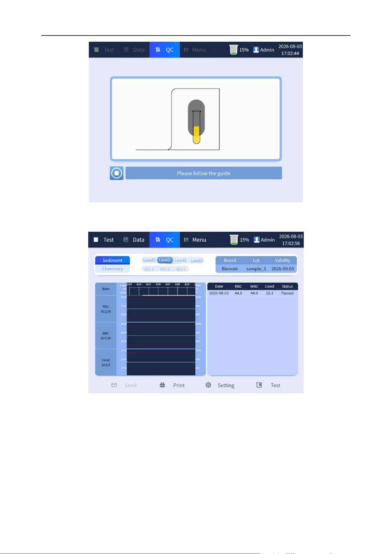
Chapter 7 Quality Control
76
Figure 7-10 Quality control tests
Figure 7-11 Completion of quality control tests
7.3.2 Chemistry quality control settings and tests
7.3.2.1 Item selection
On the quality control interface, select "Chemistry" and the corresponding gear (the selected item is
displayed with the dark blue bottom), as shown in Figure 7-12 below. On the quality control interface,
click [Settings] button to enter the newly created interface. As shown in Figure 7-13 below:
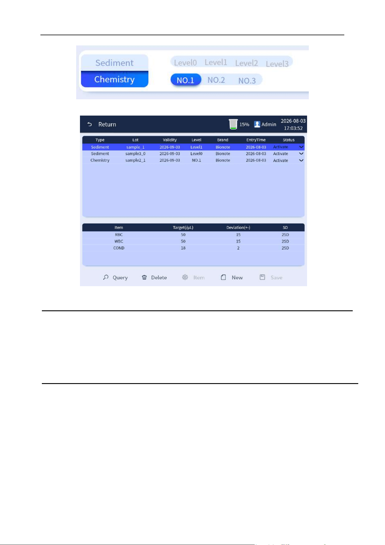
Chapter 7 Quality Control
77
Figure 7-12 Item selection
Figure 7-13 Newly created interface
Note
⚫ For the setting and testing of different gears of quality control, please select different
gears in the "Item selection" step. Other settings and testing methods are the same.
⚫ Selected items are identified in dark blue background.
7.3.2.2 Data filling and saving
Click [New] button to enter the new interface. Fill in the corresponding information such as "Type",
"Lot", "Validity" and "Level" according to the quality control material information, and fill in the data of
each input level of item data such as "VC" and "CA", as shown in Figure 7-14 below:
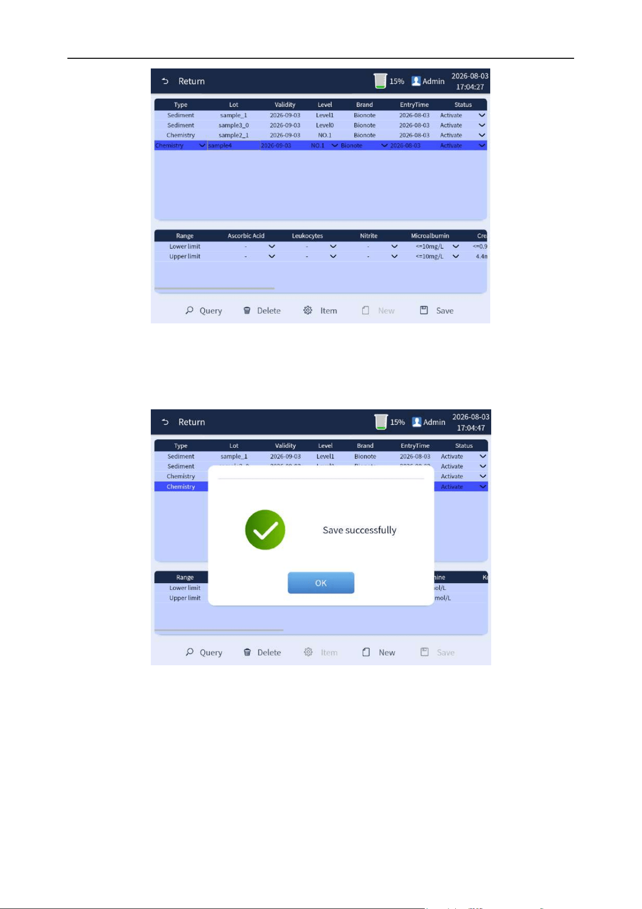
Chapter 7 Quality Control
78
Figure 7-14 Data filling of quality control items
Click the [Save] button after completing the data filling, and click [OK] to complete the operation, as
shown in Figure 7-15 below:
Figure 7-15 Data saving of quality control
7.3.2.3 Quality control tests
After the quality control data is successfully saved, click the [Return] button to return to the quality
control interface, and click the [Test] button to conduct the quality control test, as shown in Figure
7-16 below. Complete the quality control test as prompted.
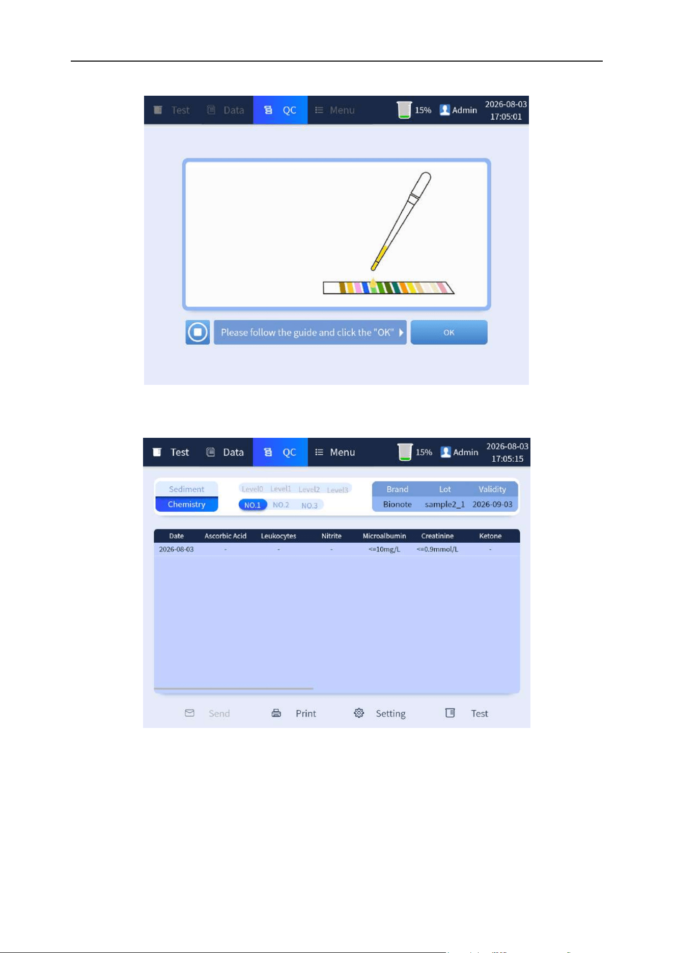
Chapter 7 Quality Control
79
Figure 7-16 Quality control tests
Figure 7-17 Completion of quality control tests
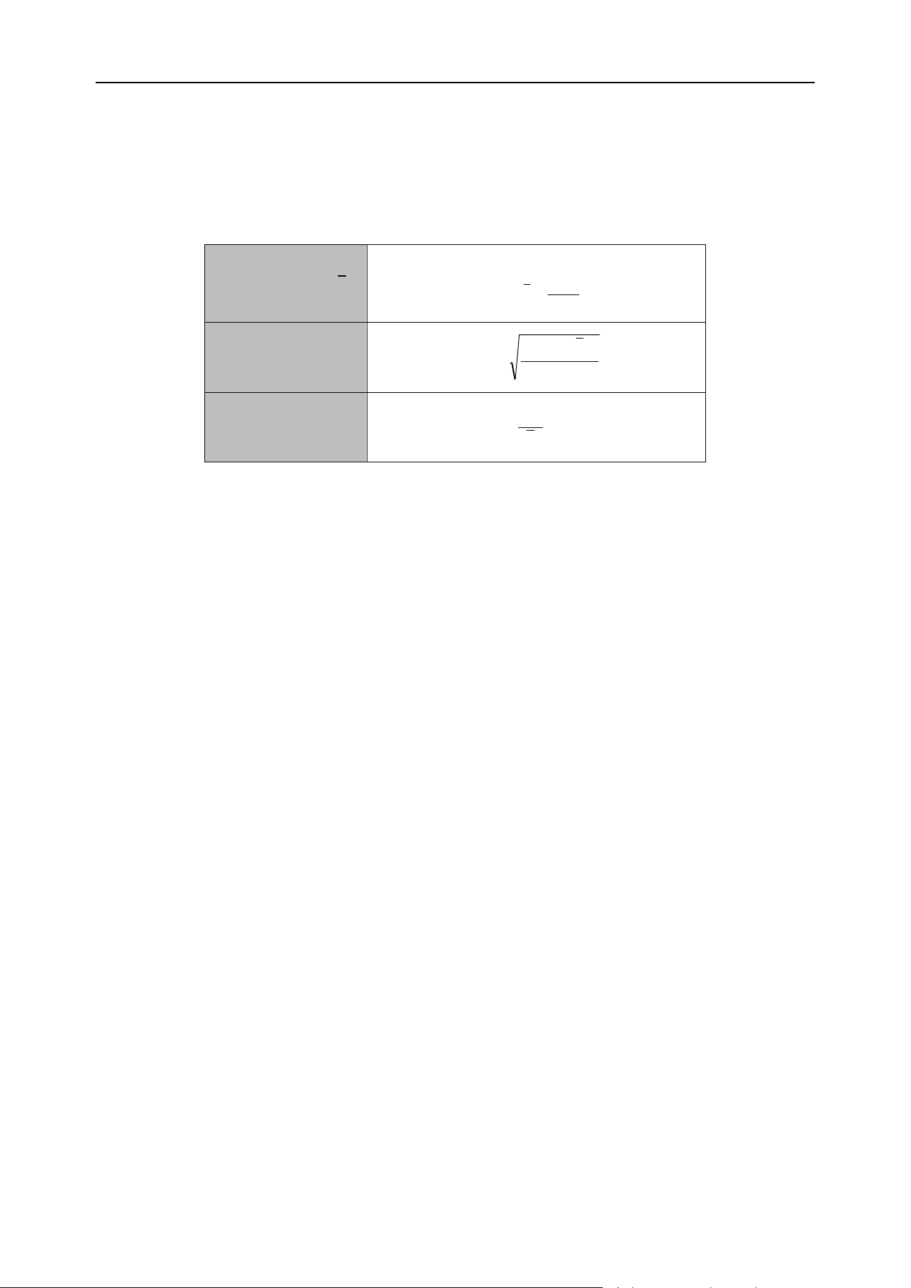
Chapter 7 Quality Control
80
7.4 Quality control algorithm
The calculation method for quality control test results is shown in table 7-1 below:
Table 7-1 Quality control algorithm
Average value (
x
)
n
x
x
n
i
i
=
=
1
Standard deviation
(SD)
1
)(
2
−
−
=
n
xx
SD
i
The coefficient of
variation (CV)
%100=
x
SD
CV
7.5 Quality control printing
Print quality control test results. Click [Print] button, and the pop-up box prompts "Print or not". Click
[Yes] button to print the quality control report.

81
Chapter 8 Analyzer Calibration
8.1 Overview
Calibration is to obtain accurate measurement results and to determine the deviation correction
coefficient for urine analysis under specified conditions. To obtain accurate analysis results of urine
samples, the analysis system should be calibrated as required by the steps given in this chapter.
Calibration in this chapter is to compare the results obtained with the actual results and then corrects
the calibration coefficients. The purpose of calibration is to make the results more accurate.
Note
⚫ The analysis system needs to be calibrated before first use.
⚫ The analysis system needs to be calibrated after the main parts have been replaced.
⚫ If the host is not used for a long time, calibration is required when the host is restored
to use.
⚫ If there are obvious deviations in the quality control data of the day, calibration is
required.
⚫ The analyzer must be calibrated before the measured data can be used as valid data.
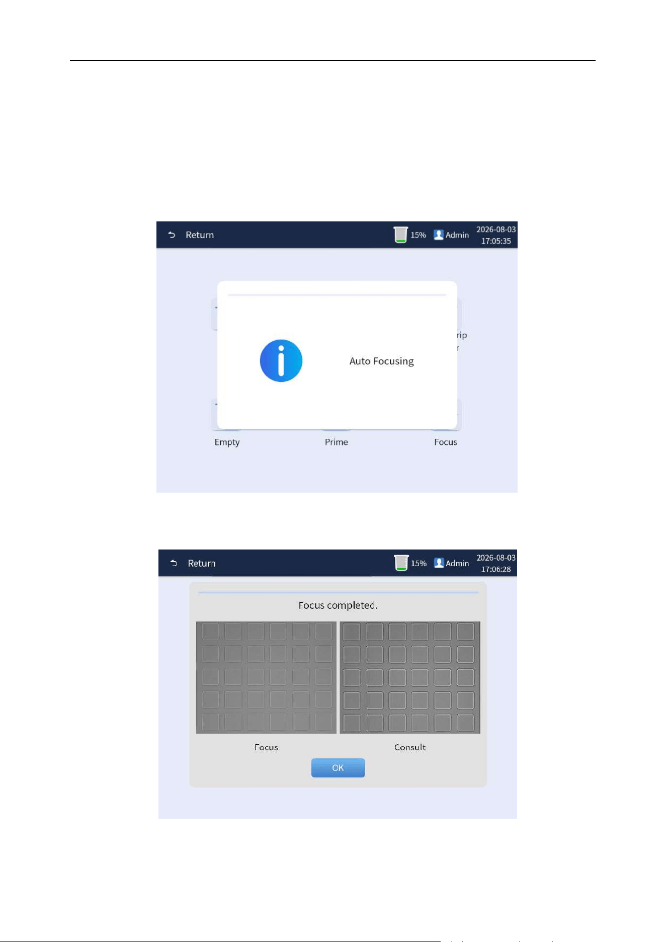
Chapter 8 Analyzer Calibration
82
8.2 Microscope calibration operation
8.2.1 Microscope calibration
Click [Menu]→[Maint.]→[Focus] button, and the analyzer will automatically perform the microscope
focusing calibration operation, as shown in Figure 8-1. After successful focusing, a window will pop
up, then click [OK] button to complete the operation, as shown in Figure 8-2.
Figure 8-1 Auto focusing
Figure 8-2 Successful focusing interface
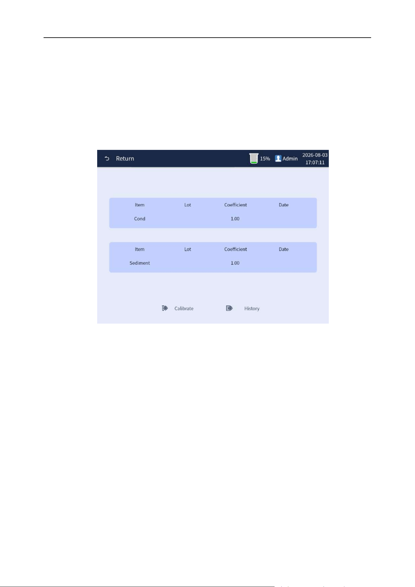
Chapter 8 Analyzer Calibration
83
8.3 Calibration of calibrator
When the measured result is larger or smaller than the actual value each time, it can be corrected by
calibration of calibrator.
Usage
Step 1: Click [Menu] on the main interface to enter the menu interface, and then click [Calib.] button
to enter the calibration interface, as shown in Figure 8-3 below.
Figure 8-3 Calibration interface
Step 2: Click [Calibrate] at the bottom of the calibration interface to enter the calibration test interface.
Enter the batch number of the current calibration in the "Lot" editing box and the current calibration
target value in the "Sediment target" editing box and select the parameters to be calibrated in the
check box, as shown in Figure 8-4 below.
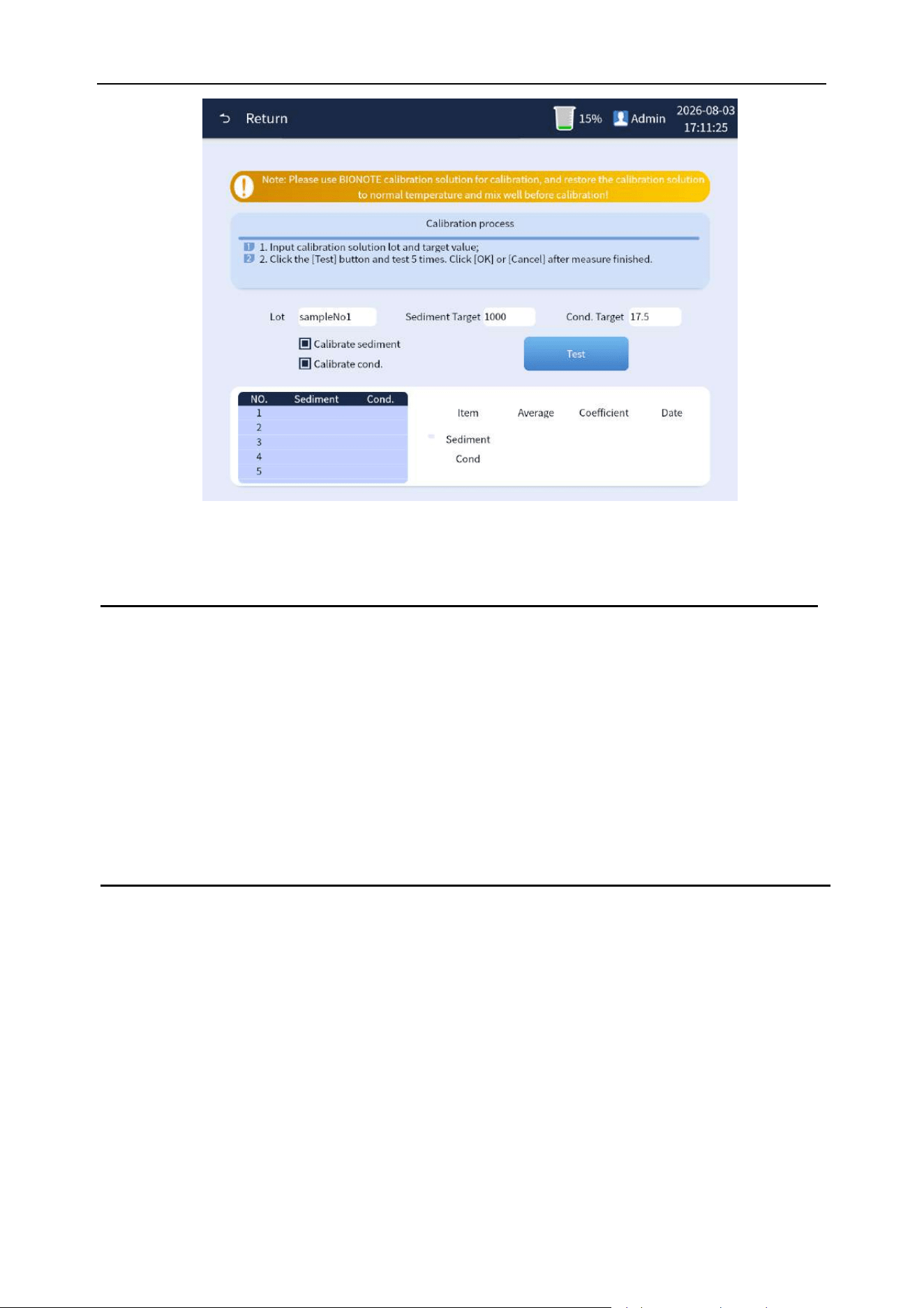
Chapter 8 Analyzer Calibration
84
Figure 8-4 Calibration test interface
Note
⚫ The operator must use the calibrator designated by BIONOTE for the analyzer.
BIONOTE will not be responsible for the incorrect analysis results caused by using
other calibrators.
⚫ The batch number, validity and parameter target values of the calibrator are given in
the instructions of the calibrator.
⚫ Batch numbers cannot be blank.
Step 3: Prepare the calibrator according to the instructions of the calibrator. Click the [Measure]
button to enter the first calibration test and place the calibrator under the sample probe as directed.
Press the analyzer 's suction key of the analyzer to draw the calibrator for the calibration test and
display the calibration test result values in the lower left window, as shown in Figure 8-5 below.
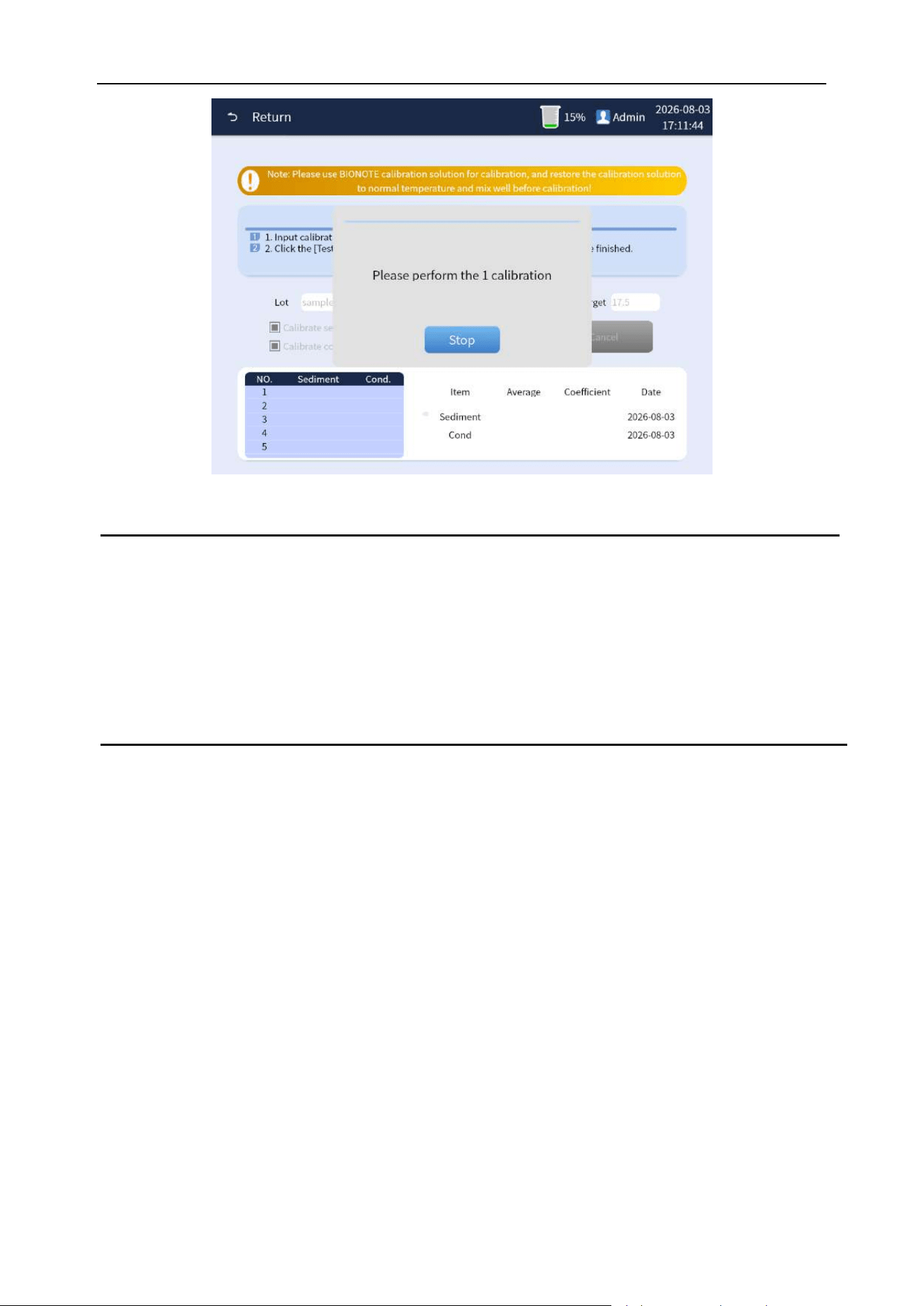
Chapter 8 Analyzer Calibration
85
Figure 8-5 Calibration test interface
Note
⚫ Once the operator clicked the "Measure" button and pressed the suction key to start
the first calibration test. Thereafter, the operator can continue the calibration test by
directly pressing the suction key on the analyzer. Calibration tests are generally
performed 5 times.
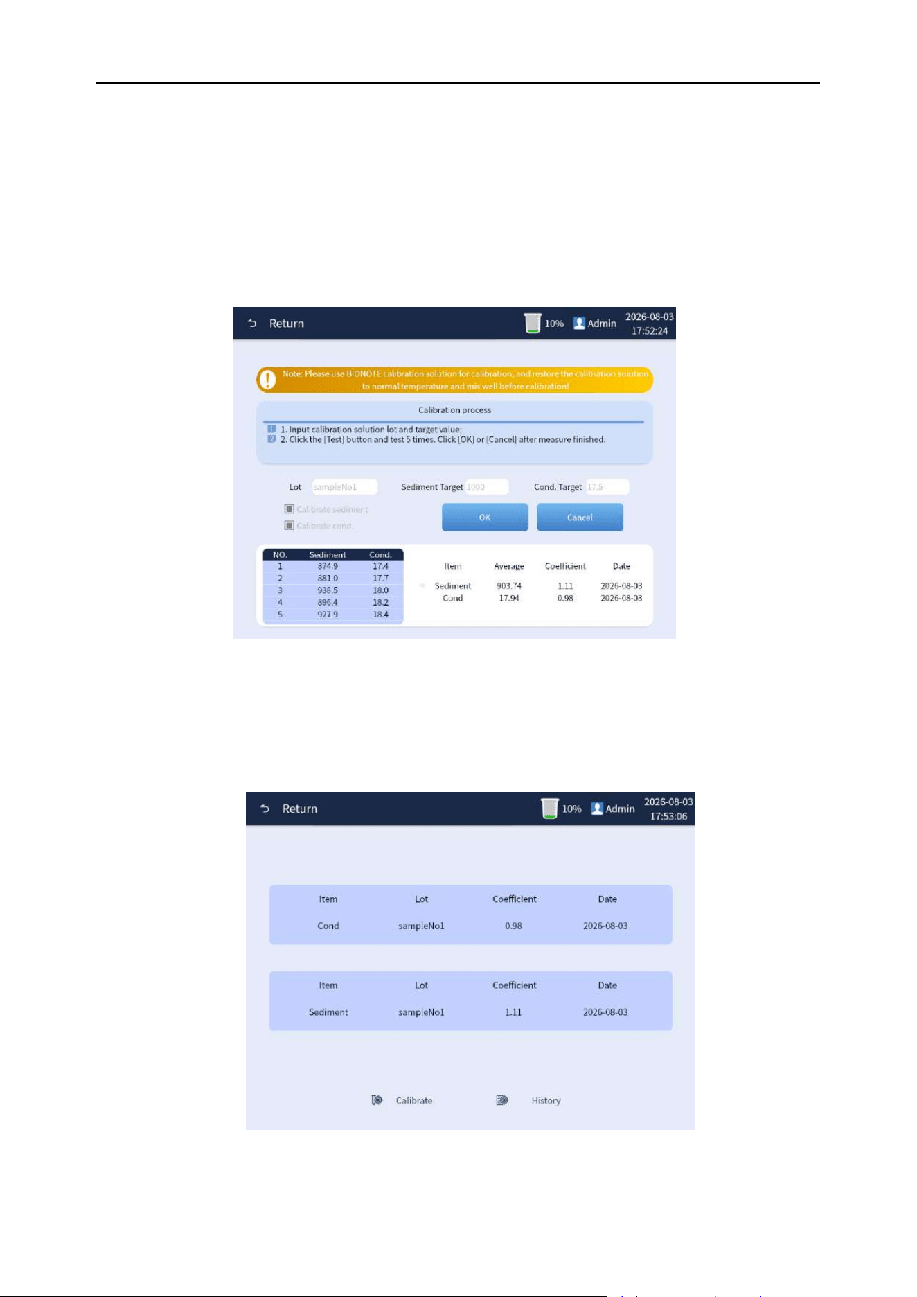
Chapter 8 Analyzer Calibration
86
Step 4: When the valid calibration counts cumulatively reach 5 times, the analyzer will automatically
tick all calibration data against the check box parameters according to the formula to perform an
automated calculation of the average value and the calibration coefficient according to the formula.
And the results are presented in the lower right corresponding bar. Click the [OK] button to save and
update the calibration coefficient. If you click the [Cancel] button, the calibration operation will be
abandoned and the old calibration coefficient will continue to be executed, as shown in Figure 8-6
below.
Figure 8-6
Step 5: Click the [Return] button on the upper left corner to return to the calibration interface. You can
check whether the calibration parameters have been updated, and batch number of calibrators and
calibration date, as shown in Figure 8-7 below.
Figure 8-7
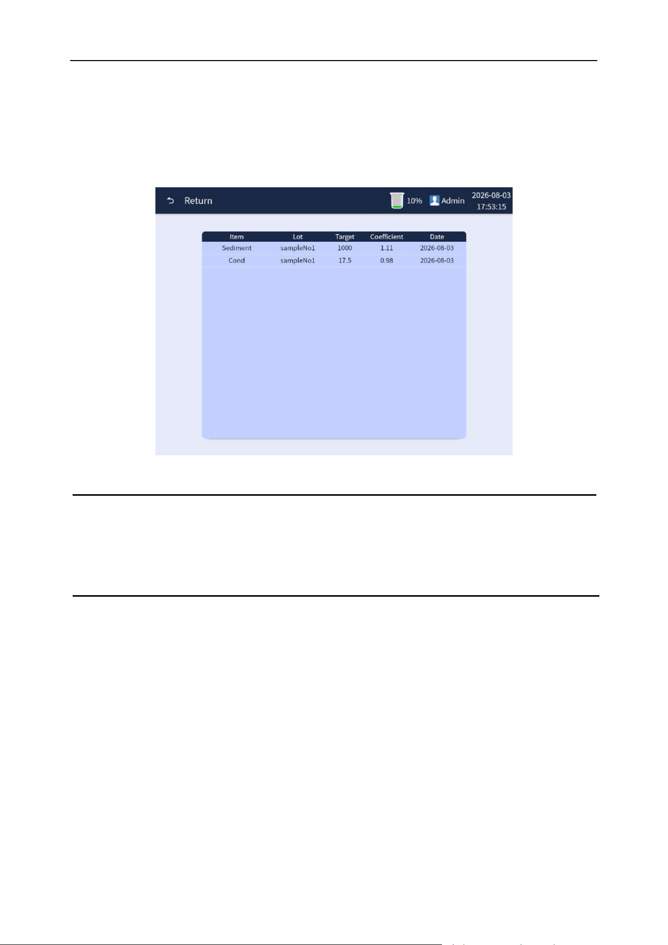
Chapter 8 Analyzer Calibration
87
8.4 Calibration history
When the calibration history of the analyzer needs to be quired, on the calibration interface, click the
[History] below the calibration interface to enter the calibration history view interface to query the
calibration history information, as shown in Figure 8-8 below.
Figure 8-8 Calibration history
Note
⚫ The analyzer has been calibrated before delivery. Since the analyzer itself is stable,
frequent calibration is not required.
88
Chapter 9 Analyzer Maintenance
9.1 Overview
The analyzer is a precision electronic optical analyzer. In order to make the analyzer accurately and
effectively operate, regular maintenance is very important. Operators perform routine maintenance
for the analysis system as required by this chapter. This analysis system provides a number of
maintenance functions to facilitate operators to complete the maintenance work.
WARNING
⚫ Read the operation manual of the analyzer and the operation manual of related test
paper and reagent carefully before operation.
⚫ Analytical analyzers and samplers must be in standby mode. Otherwise, maintenance
cannot be carried out. In addition, measurement is not allowed in the maintenance.
⚫ Avoid touching the sharp tip of the sample probe during maintenance.
Note
⚫ Cleaning of analyzer is guaranteed to maintain a good operation.
⚫ If the analyzer is not used for a long time, the fluid system should be drained, and the
analyzer should be covered with soft cloth or plastic cloth. When the analyzer is used
next time, please check with quality control products first.
⚫ Do not disassemble the analyzer at will.
⚫ If the analyzer breaks down, it should be repaired by professional maintenance
personnel authorized by BIONOTE or sent to the Maintenance Department designated
by BIONOTE.
⚫ If parts of the analyzer other than reagents need to be replaced, they should be
replaced by professional maintenance personnel authorized by BIONOTE or sent to
the Maintenance Department designated by BIONOTE.
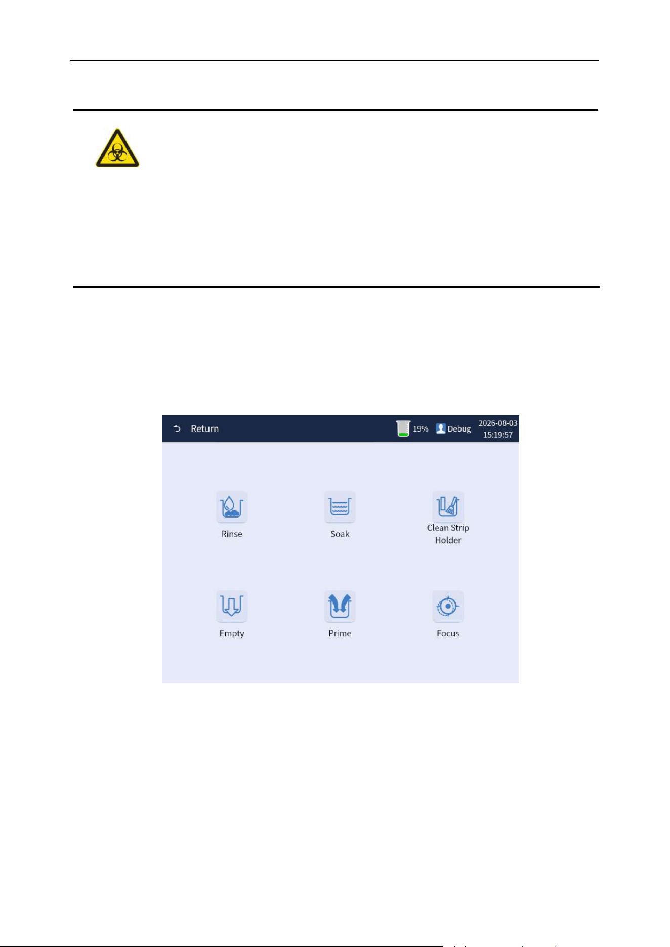
Chapter 9 Analyzer Maintenance
89
⚫ The surfaces of all the parts of the analyzer are potentially infectious. Please wear
protective gloves against bacterial infection when operating.
⚫ Disposal of waste liquid, used consumables, gauze, cotton swabs, and gloves should
be done in accordance with local decrees and regulations.
9.2 Maintenance operation interface
When the analyzer is standby, click the [Menu] button to enter the menu interface, and click the
[Maint.] button to enter the analyzer maintenance operation interface. The maintenance includes
"Rinse", "Soak" and "Clean Strip Holder" and other basic maintenance operations. As shown in
Figure 9-1.
Figure 9-1 Maintenance interface
9.3 Rinse
If the pipelines inside the analyzer are dirty or have air bubbles, the maintenance operations of
cleaning and flushing can be performed. While the analyzer is on standby, click
[Menu]→[Maint.]→[Rinse] button, and the analyzer is rinsed and flushed, and the analyzer will pop up
window showing that the analyzer is in a cleaning and flushing operation. As shown in Figure 9-2.
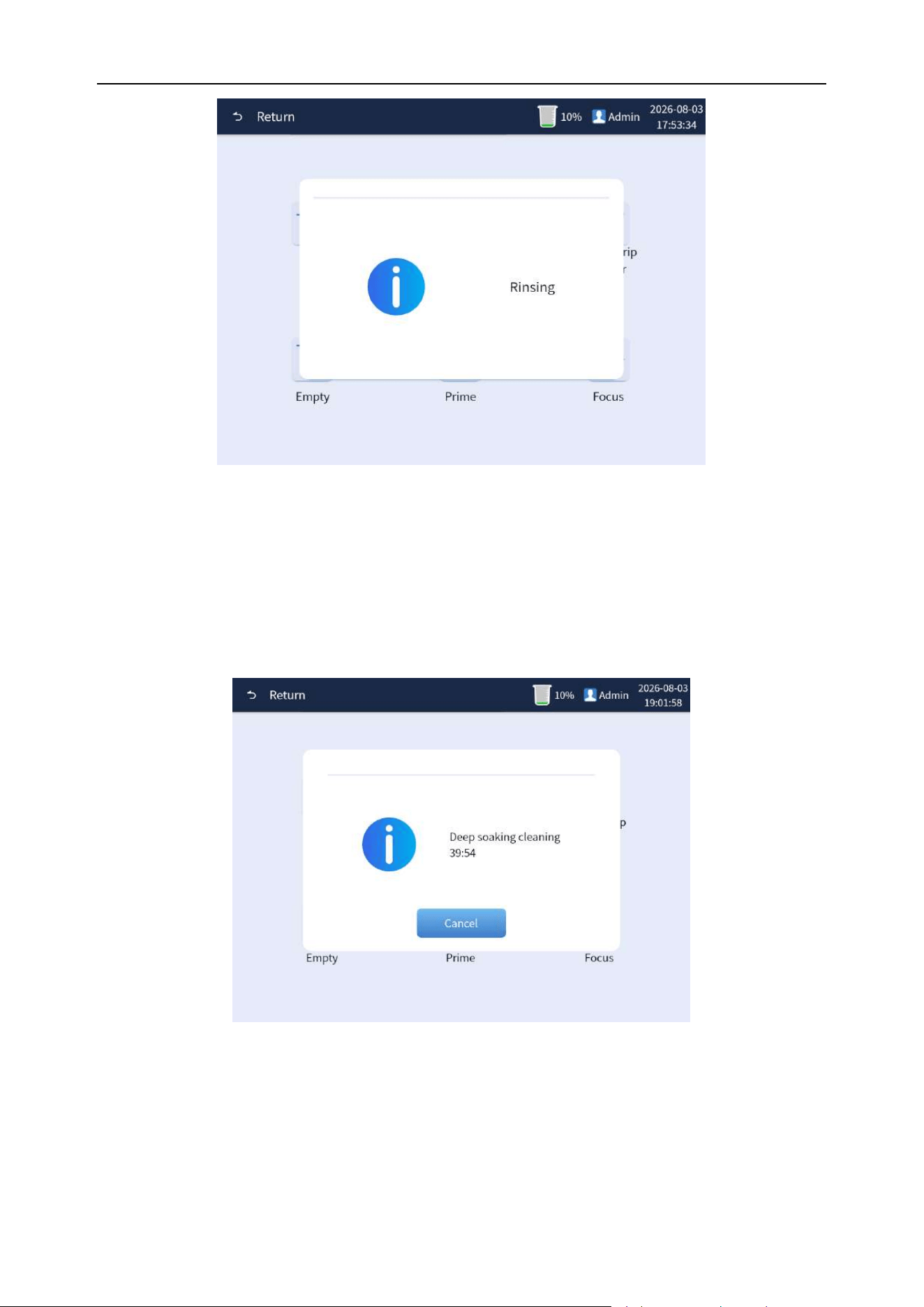
Chapter 9 Analyzer Maintenance
90
Figure 9-2 Cleaning and flushing execution interface
9.4 Soak
The analyzer has a powerful cleaning function. While the analyzer is on standby, click
[Menu]→[Maint.]→[Soak] button, and the analyzer is in a powerful soak operation, and the analyzer
will pop up window showing that the analyzer is in a powerful soak operation. As shown in Figure 9-3.
Figure 9-3 Powerful soak execution interface
9.5 Clean Strip Holder
The test tray of the analyzer should be cleaned after the daily test. While the analyzer is on standby,
click [Menu]→[Maint.]→[Clean Strip Holder] button, the analyzer front shell compartment opens and
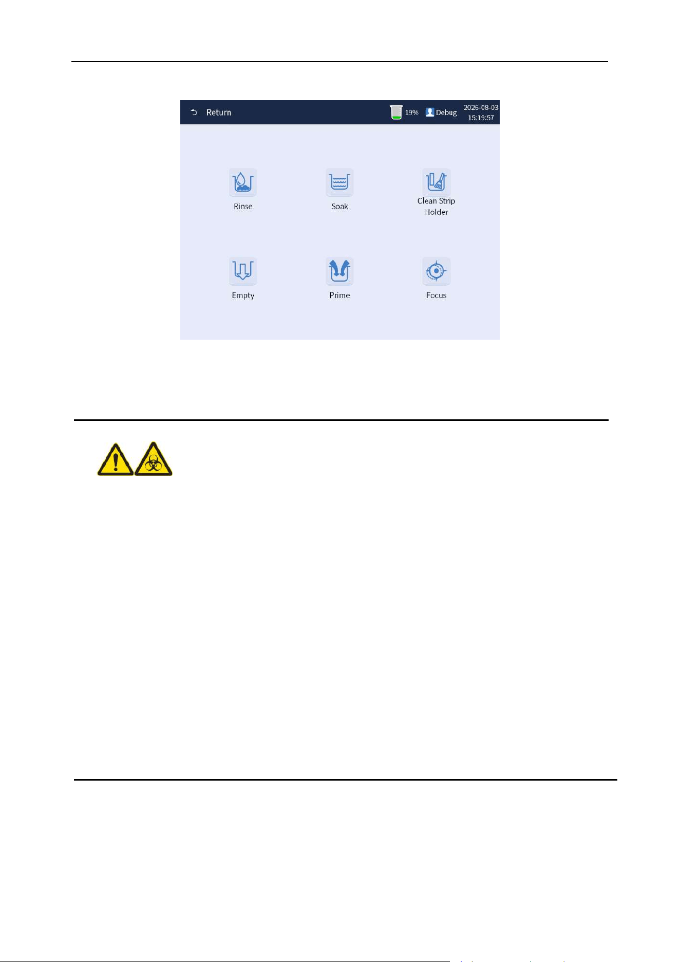
Chapter 9 Analyzer Maintenance
91
ejects "test bracket" and "test tray". The software display interface is shown in Figure 9-4.
Figure 9-4 Test tray cleaning interface
⚫ The surfaces of all the parts of the analyzer are potentially infectious. Please wear
protective gloves against bacterial infection when operating.
⚫ Dispose of waste liquid, used consumables, gauze, cotton swabs, and gloves should
be done in accordance with local decree regulations.
⚫ The chemistry test paper inlet will have a test bracket outstretch. Please pay attention
to reserve space (at least 12 cm), and do not block the door to prevent the analyzer
from working abnormally or even being damaged.
⚫ The test bracket is a moving part made of plastic. Its edge, convex, corner and other
parts are smooth and round, and the movement speed is very slow. Before it stops
moving, the operator shall not touch the part to avoid danger, and is not allowed to
contact without training.
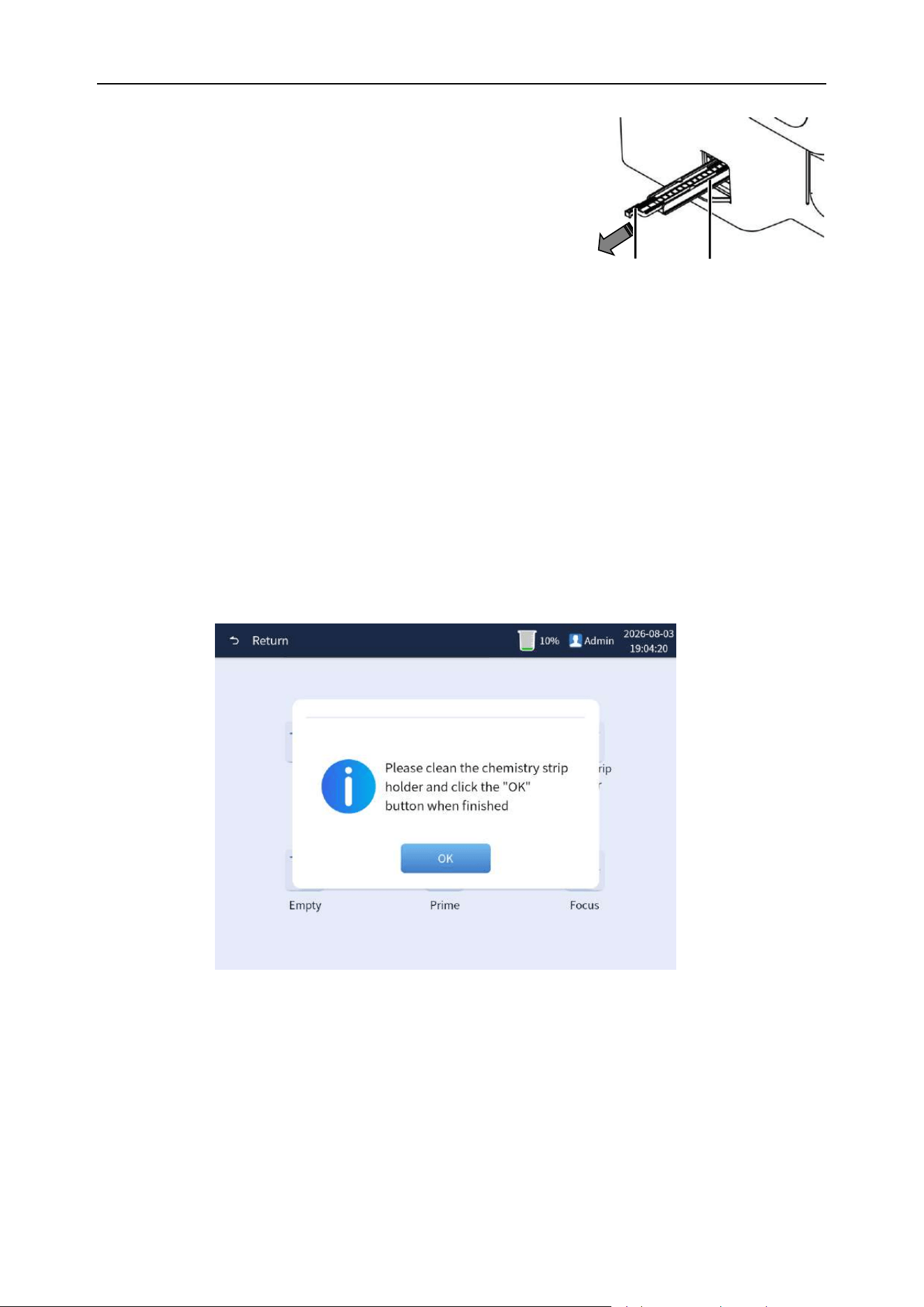
Chapter 9 Analyzer Maintenance
92
Test bracket
Test tray
Cleaning is performed as follows:
Step 1: Software interface operation
Click the [Clean Strip Holder] button and wait for the test
bracket to pop out. It is essential that the test bracket stops
moving before proceeding to the next step.
Step 2: Clean the test tray
1) The "test strip tray" is drawn off and cleaned with alcohol and then rinsed with water.
2) Dry the test strip tray with cotton cloth.
3) Wipe with cotton cloth dipped in alcohol.
Step 3: Reinstall the test strip tray
Place the test strip tray back in place.
Step 4: Software menu interface operations
After the cleaning and installation, click the [OK] button on the software menu interface to
automatically recycle the test bracket and complete the cleaning and maintenance of the test tray.
As shown in Figure 9-5 below
Figure 9-5
9.6 Empty
The analyzer has a function of emptying. While the analyzer is standby, click the [Menu]
→[Maint.]→[Empty] button, and the analyzer performs the draining operation, and the analyzer will
pop up window showing that the analyzer is performing the draining operation. As shown in Figure
9-6.
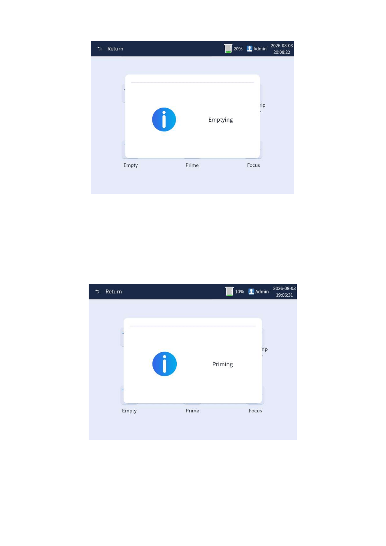
Chapter 9 Analyzer Maintenance
93
Figure 9-6 Draining execution interface
9.7 Priming
The analyzer has a priming function. While the analyzer is standby, click the [Menu]
→[Maint.]→[Prime] button, and the analyzer performs the perfusion operation, and the analyzer will
pop-up window showing that the analyzer is performing the priming operation. As shown in Figure 9-7.
Figure 9-7 Priming detergent execution interface
9.8 Auto focusing
If auto focusing is necessary when the microscope is out of focus or analyzer prompts, and when the
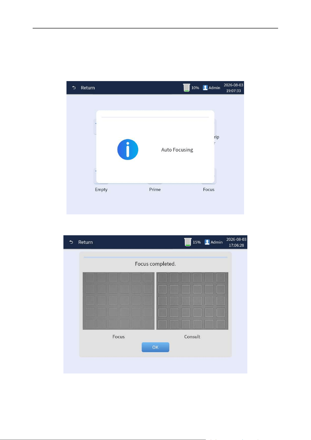
Chapter 9 Analyzer Maintenance
94
analyzer is standby, click the [Menu] →[Maint.]→[Focus] button, as shown in Figure 9-8. The analyzer
will pop up window showing that the analyzer is performing the automatic focusing operation. After
the completion, the window of focusing success will pop up. Click the [OK] button to complete the
operation, as shown in Figure 9-9.
Figure 9-8 Auto focusing execution interface
Figure 9-9 Auto focusing

Chapter 9 Analyzer Maintenance
95
9.9 Cleaning and maintenance
The surface stains of the analyzer, especially the possible residual urine sample splashing around
sampling keys, must be rinsed and cleaned weekly to prevent the deposition, mold, and
contamination of the sample. Clean the surface around the sample probe of the analyzer with a neat
and tidy cloth dipped in a neutral detergent, and then clean other surfaces.
Note
⚫ Do not use corrosive acid, alkali and powerful volatile organic solvent, such as
acetone, ether, chloroform, etc. to scrub the surface of the analyzer. Only neutral
detergent can be used.
⚫ If you have any questions about the compatibility of cleaning agents with equipment
parts or materials contained in the analyzer, please consult with BIONOTE or agents
designated by BIONOTE.

96
Chapter 10 Fault Handling
10.1 Overview
This chapter describes the information about possible faults of analysis system and provides the
corresponding solutions.
If faults still are not ruled out in accordance with the working guidelines of this chapter or more
detailed information is required, please contact BIONOTE. The fault handling guideline is designed to
assist users in finding and excluding faults during an analyzer 's operation, and the guideline also
gives a way for users to get timely technical support and assistance from the BIONOTE. The
excellent fault finding and exclusion skills results from an intimate knowledge of the analyzer and the
day-to-day accumulation of the experience gained during its use. The more that is known, the easier
it will be to find and rule out.
To look up and rule out faults accurately and quickly, first, read through the manual and know the
normal operation of the analyzer and the preventive care and maintenance.
Note
⚫ The operation manual is not part of the service manual and provides only measures
that the operator should take when there is a fault alarm in the analytical system.
10.2 Approach to fault handling
In general, the handling of faults should be performed in three steps as follows:
1) Fault confirmation
2) Fault classification
3) Fault clearing
Step 1: Fault confirmation
The operator can not only confirm the reason for the fault but also know what should be correct under
normal circumstances. Only the correct confirmation of the fault can be rectified.
Step 2: Fault classification
The fault classification of analyzer can be roughly divided into the following three categories:
1) Hardware-related faults.

Chapter 10 Fault Handling
97
2) Software-related faults.
3) Test faults related to sample analysis.
All faults related to hardware and software can only be repaired by BIONOTE or engineers with
corresponding qualifications authorized by BIONOTE. Test faults related to sample analysis can be
ruled out by the operator under the guidance of BIONOTE engineers.
Step 3: Fault clearing
Maintenance engineers take appropriate measures and steps to clear the fault. If the operator can
clear the fault on his/her own or with the help of BIONOTE engineers, the time delayed will be greatly
reduced.
10.3 Seeking technical support
If the analyzer breaks down and requires technical support from BIONOTE, please call BIONOTE or
contact the local BIONOTE office. See the preface for the contact number and fax. When seeking
technical support, users must provide a detailed and clear description of the problem and related
information. The details are as follows:
1) Type of analyzer.
2) Serial number and version number of the analyzer.
3) Describe the fault symptoms and operating environment in detail (for example, what
operations are performed in what window and state).
4) Batch No. of reagent used.
5) Fault-related data, reports.
This chapter gives the list of common faults of the analyzer and the solutions. When the analyzer
breaks down, the operator can find out the cause of the fault according to the alarm message sent by
the analyzer and perform according to the fault handling methods and steps provided in this list.
10.4 Common faults and handling methods
If an error occurs, please refer to the following causes and solutions to take appropriate measures.
If an error still occurs after taking the recommended measures, or if there is a fault or damage, please
contact BIONOTE.
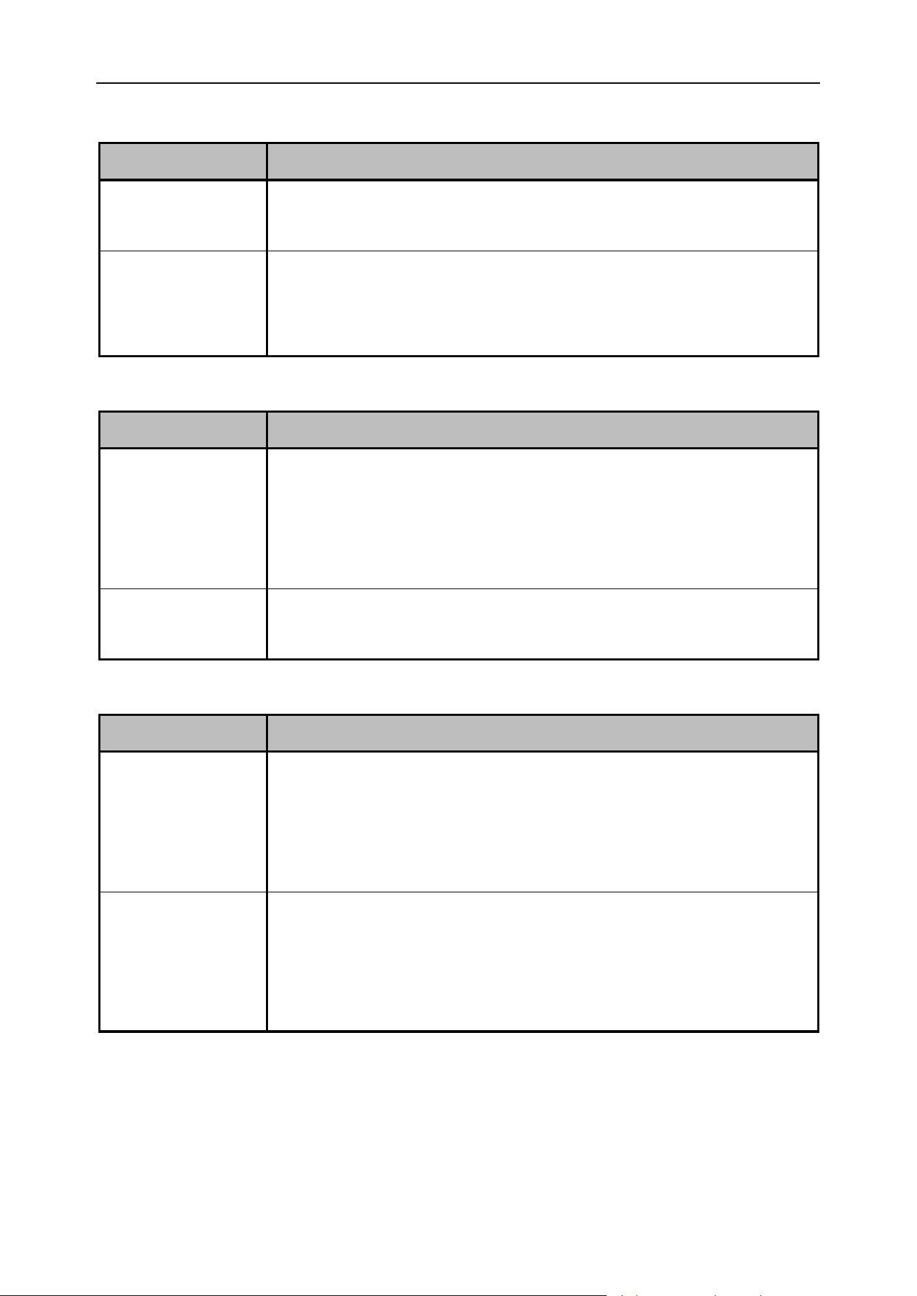
Chapter 10 Fault Handling
98
10.4.1 The host cannot be turned on
Fault problem
The host cannot be turned on
Possible causes
(1) The power socket at the site where the analyzer is used is damaged.
(2) The fuse on the rear panel of the analyzer host burns out.
Solutions
(1) Replace the power socket at the site where the analyzer is used.
(2) Contact the BIONOTE to replace the fuse on the rear panel of the
analyzer host.
10.4.2 No display after startup
Fault problem
No display after startup
Possible causes
(1) After the analyzer is powered on, the time for pressing the start touch key
is not enough.
(2) The position of the touch button is not pressed in the right place when
clicking the startup.
Solutions
(1) Press the start touch key for sufficient time.
(2) Click on the right position of the starting touch button to start up.
10.4.3 The printer cannot print
Fault problem
The printer cannot print
Possible causes
(1) The printer cable on the rear panel of the analyzer host is loose.
(2) The power cord of the printer and the on-site power socket are not
connected properly.
(3) The printer's power switch is not turned on.
Solutions
(1) Reconnect the printer cable with the relevant interfaces on the rear
panel of the analyzer host.
(2) Connect the power cord of the printer to the on-site power socket.
(3) Turn on the printer’s power switch.
Chapter 10 Fault Handling
99
10.4.4 A warning message displays on the screen: Little or no detergent
Fault information
Little or no detergent
Possible causes
The detergent in the reagent container has been used up.
Solutions
Replace reagent. (See "Chapter 3, section 3.6 Installation of Reagent" for
details of reagent replacement.)
10.4.5 An alarm message displays on the screen: The waste liquid is full
Fault information
The waste liquid is full
Possible causes
(1) The waste liquid in the waste liquid bottle is full.
(2) The waste liquid sensor cable is loose.
Solutions
(1) Dispose the waste liquid.
(2) Connect the waste liquid sensor cable to the relevant interface on the
rear panel of the analyzer host.
10.4.6 An alarm message displays on the screen: No reagent is detected
Fault information
No reagent is detected
Possible causes
The reagent is not pushed in place.
Solutions
Put the reagent interface in the right place of the suction clamp and push it
into place with appropriate force.
10.4.7 An alarm message displays on the screen: No card is available or a card reading error
Fault information
No card is available or a card reading error
Possible causes
(1) The reagent is not pushed in place.
(2) The reagent has been used.
(3) The encryption card information of the reagent has been damaged.
Solutions
(1) Put the reagent interface in the right place of the suction clamp and
push it into place with appropriate force.
(2) Replace with the new unused reagent.
(3) Replace it with a new reagent. Contact BIONOTE.

Chapter 10 Fault Handling
100
10.5 Fault code table
Table 10-1 List of fault codes
Fault Code
Fault Prompt Information
Solution
T-0101
Chemistry communication is
disconnected
1. Check the connection wires of the
chemistry module.
2. Click “Resolve” and connect again.
T-0102
Reagent registration timeout
Eliminate directly.
T-0103
Camera communication is
disconnected
1. Confirm that the IP of the network card
is correct.
2. Click “Resolve” and connect camera
again.
T-0104
Analyzer communication is
disconnected
1. Check CAN communication lines.
2. Click “Resolve” and connect the underlying.
T-0221
Sampling motor error, please
check the optocoupler and motor
connection after the "Resolve"
button
1. Check the optocoupler and motor
connection wires.
2. Click “Resolve” and reset the underlying.
T-0222
X axis motor error, please check
the optocoupler and motor
connection after the "Resolve"
button
1. Check the optocoupler and motor
connection wires.
2. Click “Resolve” and reset the underlying.
T-0223
Y axis motor error, please check
the optocoupler and motor
connection after the "Resolve"
button
1. Check the optocoupler and motor
connection wires.
2. Click “Resolve” and reset the underlying.
T-0224
Z axis motor error, please check
the optocoupler and motor
connection after the "Resolve"
button
1. Check the optocoupler and motor
connection wires.
2. Click “Resolve” and cancel the fault.

Chapter 10 Fault Handling
101
T-0225
Injection pump motor error,
please check the optocoupler
and motor connection after the
"Resolve" button
1. Check the optocoupler and motor
connection wires.
2. Click “Resolve” and reset the underlying.
T-0226
Reagents pack motor error,
please check the motor after the
"Resolve" button
1. Check the optocoupler and motor
connection wires.
2. Click “Resolve” and cancel the fault.
T-0227
Reagents have been used up,
please register the reagents
Click “Resolve” and replace reagents.
T-0228
No reagent pack, please click
"Resolve" button after replacing
Click “Resolve” and replace reagents.
T-0229
Camera initialization failed. Click
"Resolve" button to restart the
system
Click “Resolve”. Power off the analyzer and
power on manually.
T-022A
The waste is full, please clean
up the waste liquid and click
"Resolve" button
1. Clear up liquid waste.
2. Click “Resolve” and reset the underlying.
T-022B
Cannot detect the reagent.
Please try Priming or changing
the package
Click “Resolve” and replace reagents.
T-0241
No card reader or failed to
connect the card reader
Click “Resolve” and reset the underlying.
T-0242
Reagent registration failed
Eliminate directly.
T-0243
Error in reagent card data
Eliminate directly.
T-0251
The conductivity module
connection failed. Please check
the "Resolve" button after the
conductivity module connection
Click “Resolve”, reset and connect again to
read version number.
T-0601
Chemistry infrared led error
Inspect and repair chemistry module.
T-0602
Chemistry red led error
Inspect and repair chemistry module.
T-0603
Chemistry green led error
Inspect and repair chemistry module.

Chapter 10 Fault Handling
102
T-0604
The strip is not in the right
position.
Click “Resolve” and cancel the fault.
T-0605
Error strip type
Click “Resolve” and cancel the fault.
T-0606
Cannot detect strip
Click “Resolve” and cancel the fault.
T-0607
Chemistry motor error
Eliminate directly.
103
Appendix A Specifications
A1.Outline Specification Size and Weight
Size
465Mm (length) × 270mm (width) × 405mm (high)
Weight
18.0KG
A2.Normal working environment
Ambient
temperature
5–40 ℃
Relevant
humidity
30–85 %RH
Atmospheric
pressure
60–106 kPa
A3.Storage and transportation environment
Ambient
temperature
-10 – 55 ℃
Relevant
humidity
≤93 %RH
Atmospheric
pressure
60–106 kPa
A4.Electrical specification
Power supply
AC 100V–240V 50/60Hz
Fuse
T3.15A L250V
Power
120VA
A5.Storage capacity
The analyzer can store 100,000 test results.

104
Appendix B: List of Main Replacement Parts
No.
Name
Remarks
1
Switching power supply
2
Fuse
3
Camera
4
40X Objective lens
5
Three-way solenoid valve
6
Syringe
Motor containing
7
Vacuum pump
8
Liquid pump
9
Plastic pipe
10
Silicone tube
11
Sample probe
12
Probe wiper
13
Main control board
14
Industrial control computer
15
Display screen
16
Chemistry detection module
Motor containing
Note
⚫ Please use the device specified by BIONOTE for analyzer maintenance and device
replacement. The analyzer must be replaced by the person authorized by BIONOTE
when maintaining the device.
⚫ BIONOTE assumes no responsibility for any consequences caused by the use of
devices not approved by BIONOTE.
⚫ The above list of replacement devices is for reference only, and BIONOTE has the
final interpretation right of specific replacement devices.

105
Appendix C: List of Annexes
No.
Product name
Quantit
y
Remarks
1
Vcheck U3
1
2
Quick Guide
1
In accessory case
3
Installation guide
1
4
Plastic bucket (5L)
1
5
Power cord
1
In accessory case
6
External pipe components
1
In accessory case
7
Bio-safety urine sediment test tube type(II)
10
In accessory case
8
Chemistry module strip tray
3
In accessory case
9
Calibration strip package
1
In accessory case
10
Test tube holder
1
11
Touch pen
1

106
Appendix D: Unit Results Comparison Table
Test items
Semi-quantitative symbols and related concentration values
unit
NO.1
NO.2
NO.3
NO.4
NO.5
NO.6
WBC
Symbol Unit
-
+-
+1
+2
+3
/
Traditional
Unit
leu/μL
0
15
70
125
500
/
international
unit
CELL/μL
0
15
70
125
500
/
KET
Symbol Unit
-
+-
+1
+2
+3
/
Traditional
Unit
mg/dL
0
5
15
40
80
/
international
unit
mmol/L
0
0.5
1.5
4.0
8.0
/
NIT
Symbol Unit
-
+
/
/
/
/
Traditional
Unit
Neg
Pos
/
/
/
/
international
unit
Neg
Pos
/
/
/
/
URO
Symbol Unit
Normal
+1
+2
+3
/
/
Traditional
Unit
mg/dL
Normal
2.0
4.0
8.0
/
/
international
unit
μmol/L
Normal
33
66
131
/
/
BIL
Symbol Unit
-
+1
+2
+3
/
/
Traditional
Unit
mg/dL
0
0.5
2.0
6.0
/
/
international
unit
μmol/L
0
8.6
33
100
/
/
PRO
Symbol Unit
-
+-
+1
+2
+3
/
Traditional
Unit
mg/dL
0
15
30
100
300
/
international
unit
g/L
0
0.15
0.3
1.0
3.0
/
GLU
Symbol Unit
-
+-
+1
+2
+3
+4
Traditional
Unit
mg/dL
0
50
100
250
500
1000
international
unit
mmol/L
0
2.8
5.5
14
28
55
SG
international
unit
1.000
1.010
1.015
1.020
1.030
1.040
1.045
1.050
1.060
pH
international
unit
5.0
5.5
6.0
6.5
7.0
7.5
8.0
8.5
9.0
/
BLD
Symbol Unit
-
+-
+1
+2
+3
/
Traditional
Unit
mg/dL
0
0.03
0.075
0.24
0.6
/
international
unit
CELL/μL
0
10
25
80
200
/
CR
Traditional
Unit
mg/dL
10
50
100
200
300
/
international
unit
mmol/L
0.9
4.4
8.8
17.6
26.4
/
MA
Traditional
Unit
mg/dL
1
3
8
15
/
/

Appendix D: Unit Results Comparison Table
107
international
unit
mg/L
10
30
80
150
/
/
VC
Symbol Unit
-
+-
+1
+2
+3
/
Traditional
Unit
mg/dL
0
10
25
50
100
/
international
unit
mmol/L
0
0.6
1.4
2.8
5.6
/
Ca
Traditional
Unit
mg/dL
4
10
20
30
40
/
international
unit
mmol/L
1.0
2.5
5.0
7.5
10.0
/
UPC
(dog&
other)
Calculated
value
<0.2
0.2to<0.5
0.5to<1.0
1.0to<2.0
>2.0
/
UPC
(cat)
Calculated
value
<0.2
0.2to<0.4
0.4to<1.0
1.0to<2.0
>2.0
/

108
Appendix E: Toxic and Hazardous Substances or Elements
Parts
Toxic and Hazardous Substances or Elements
Plumbum
(Pb)
Mercury
(Hg)
Cadmium
(Cd)
Chromium
VI (Cr (VI))
Polybromi
nated
Biphenyls
(PBB)
Polybrominated
Diphenyl Ethers
(PBDE)
Host
Shell
○
○
○
○
○
○
Printed
circuit
board
Assembly
○
○
○
○
○
○
Sheet
metal Parts
○
○
○
○
○
○
Plastic
Parts
○
○
○
○
○
○
Machining
parts
○
○
○
○
○
○
Hardware
○
○
○
○
○
○
Flow
System
Parts
○
○
○
○
○
○
Cable
○
○
○
○
○
○
Accessories
○
○
○
○
○
○
Packaging
Materials
○
○
○
○
○
○
The table is compiled in accordance with SJ/T 11364.
○: The content of toxic or hazardous substances in the homogeneous materials of
the parts above is in the acceptable range of GB/T 26572.
×: The content of toxic or hazardous substance exceeds the acceptable range of
GB/T 26572 in at least one kind of homogeneous material of the parts above.
(The circuit board used lead solder in machining process and some parts of the
board contain plumb;And some sheet metal parts use chromium VI for surface )
Memo: Printed circuit board Assembly consists of printed circuit board, capacitance,
connector and other parts. Lithium cells are detachable and recyclable part.