Central AC (T) Series
Air Handler
Instruction Manual
Installation and Operation Guide

Table of Content
Warning and Safety 04
Before Installation
Installation Location
Appliance Orientation
Refrigerant Line Connection
Drain Pipe Connection
Electrical Wiring
Duckwork
Air Filter
Auxiliary Heater
12
13
18
19
20
27
28
32
Installation
36
39
40
DIP Switch
Indicating Light
Troubleshooting
System Info
Having Problems?

Before Installation
Before Installation
Warning and Safety
• Read this guide before installation. Failure to follow the safety instructions may result in property damage, serious injury, or death.
• Please Keep this manual.
Danger:
Indicates an IMMINENTLY hazardous situation that, if not avoided, will result in death, serious injury, or serious property damage.
Warning:
Indicates an POTENTIALLY hazardous situation that, if not avoided, will result in death, serious injury, or serious property damage.
Caution:
Indicates an POTENTIALLY hazardous situation that, if not avoided, will result in minor to moderate injury. It may also be used to
indicate unsafe practice.
Attention:
Pay additional attention to the instruction.
DO NOT:
Indicates prohibited actions and / or practice.
DANGER
WARNING
CAUTION
About Refrigerant
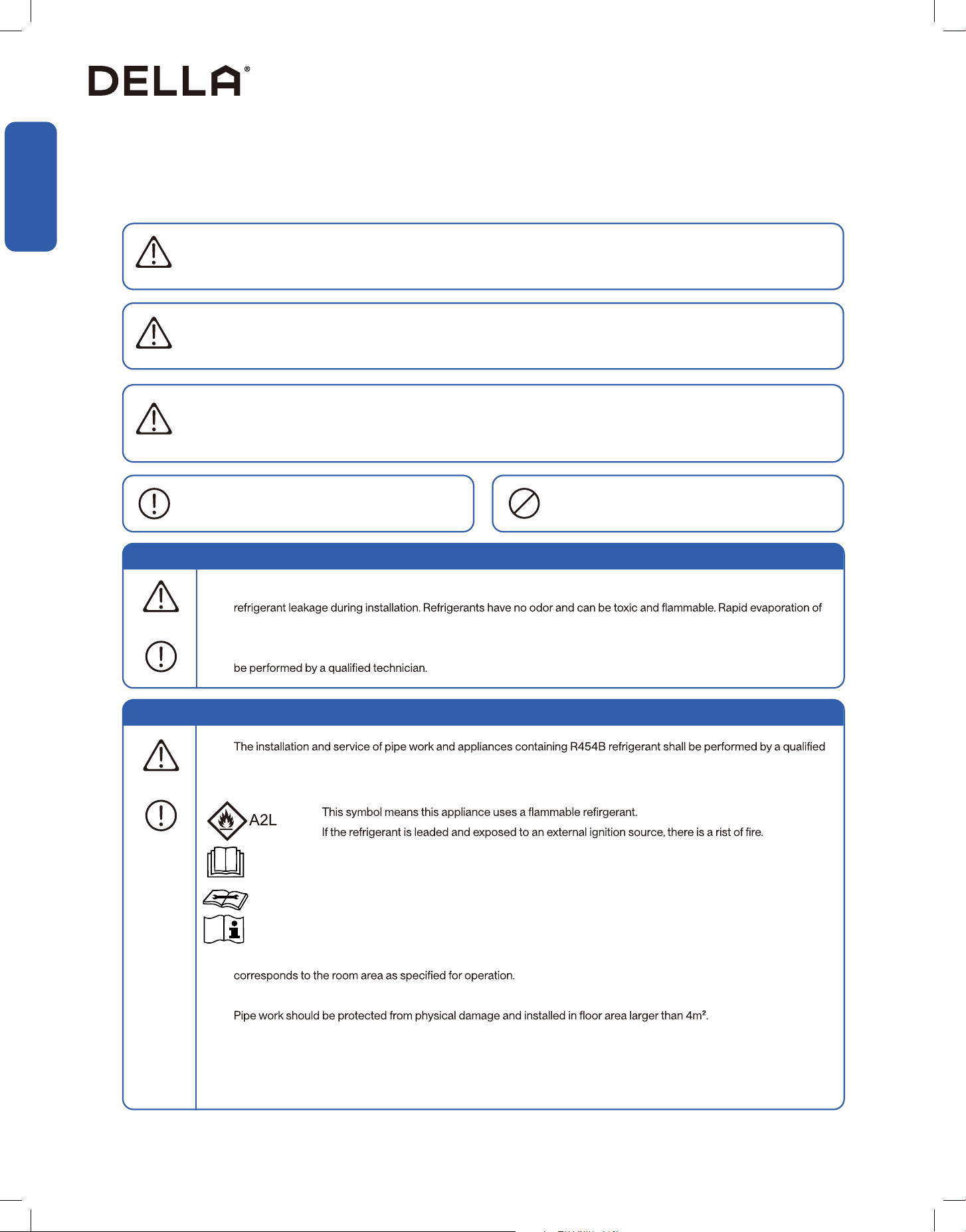
• The air conditioner is pre-charged with R454B refrigerant. Handle the air conditioner with care and check if there is any
refrigerant may cause frostbite, cardiac arrhythmia, and / or irritation, as well as cause environmental damage.
• In the case of refrigerant leakage, shut down the appliance and disconnect from the power supply. An inspection must
•
and licensed technician.
• When installing or using the appliance with R454B refrigerant, beware of the following symbols.
• Length and area limitation and recommendation should be followed. Store and install the appliance in rooms which size
• The length of pipe work should be kept at minimum.
•
• All national, state, and local regulations on handling and installing R454B refrigerant should be followed.
• Do not install or store the compressor in area or room with continuously operating ignition sources.
• Prior to any work and servicing on systems containing ammable refrigerant, safety checks are necessary to ensure that
the risk of ignition is minimized.
DANGER
Additional Information About R454B Refrigerant
WARNING
•
• This symbol means that read the operation insturction carefully.
• This symbol means that personnel handling the equipment should reference to the installation manual.
• This symbol means information is available in the installation or operation instruction manual.
Before Installation
Before Installation
Warning and Safety
•
• The work area shall be checked with refrigerant detector prior to and during work to ensure the technician is aware of
•
equipment shall be available to hand.
• Personnel carrying out work in relation to the refrigeration system which involves exposing any pipe work shall not use
displayed.
• Ensure the work area is in the open or that it is adequately ventilated before breaking into the system or conducting any
work that will produce heat. A degree of ventilation shall be kept during the period which work or service is carried out.
• During installation or repairs to sealed components, all electrical supplies shall be disconnect from the equipment. A
permanent operating leak detection shall locate at the work area to detect potential hazardous leaks.
•
Additional Information About R454B Refrigerant
WARNING
• The refrigerant charge amount is in accordance with the room size within which the refrigerant containing parts are
installed.
• The ventilation machinery and outlet are operating adequately and are not obstructed.
• If an indirect refrigerating curcuit is being used, the secondary circuit shall be check for the presence of refrigerant.
• Refrigerant pipe or components are installed in a position where they are unlilely to be exposed to any substance
which may corrode refrigerant containing components, unless the components are constructed of materials which
are inherently resistant to being corroded or are suitable protected against being corroded.
• Refrigerant charge shall be recovered into recovery cylinders, All refrigerant recovery procedure shall follow local
and national regulations. Oxygen free nitrogen shall be purged through the system after refrigerant recover.
• When decommissioning the appliance, it is recommended that all refrigerants are recovered. The system should be
isolated electrically, and recovered refrigerant should not be charged into another re
frigeration system unless it has
been analized to be safe to do so.
•
dated and signed.
• Under no circumstances shall potential sources of ignition be used in the searching for or detection of refrigerant
•
source of ignition and is suitable for the refrigerant used.
• Leak detection equipment shall be calibrated to the refrigerant employed and the appropriate percentage of gas
•
be avoided as chlorine may react with the refrigerant and corrode the pipe work.
•
• If a leakage of refrigerant found which requires brazing, all of the refrigerant shall be recovered from the system, or
• Oxygen free nitogen shall be purged through the system both before and during the brazing process.
•
• Decommissioning and recovery of refrigerants:
4

Before Installation
Before Installation
Warning and Safety
Additional Information About R454B Refrigerant
WARNING
• -
erant is suitabe for system needing additional refrigerant charge and which will limit the area of rooms being served by
the system. Similarly, the total amount of refrigerant in the system shall be less than or equal to the allowable maximum
refrigerant charge. The allowable maximum refrigerant charge depends on the area of the rooms being served by the
system.
• For R454B refrigerant, the maximum charge in a room shall be in accordance with the following:
• M = Mass
• M
max = Maximum charge mass
• M
c = Mass charged
• A = Floor area
•
1. It is a permanent opening.
2.
3. It is intened for people to walk through.
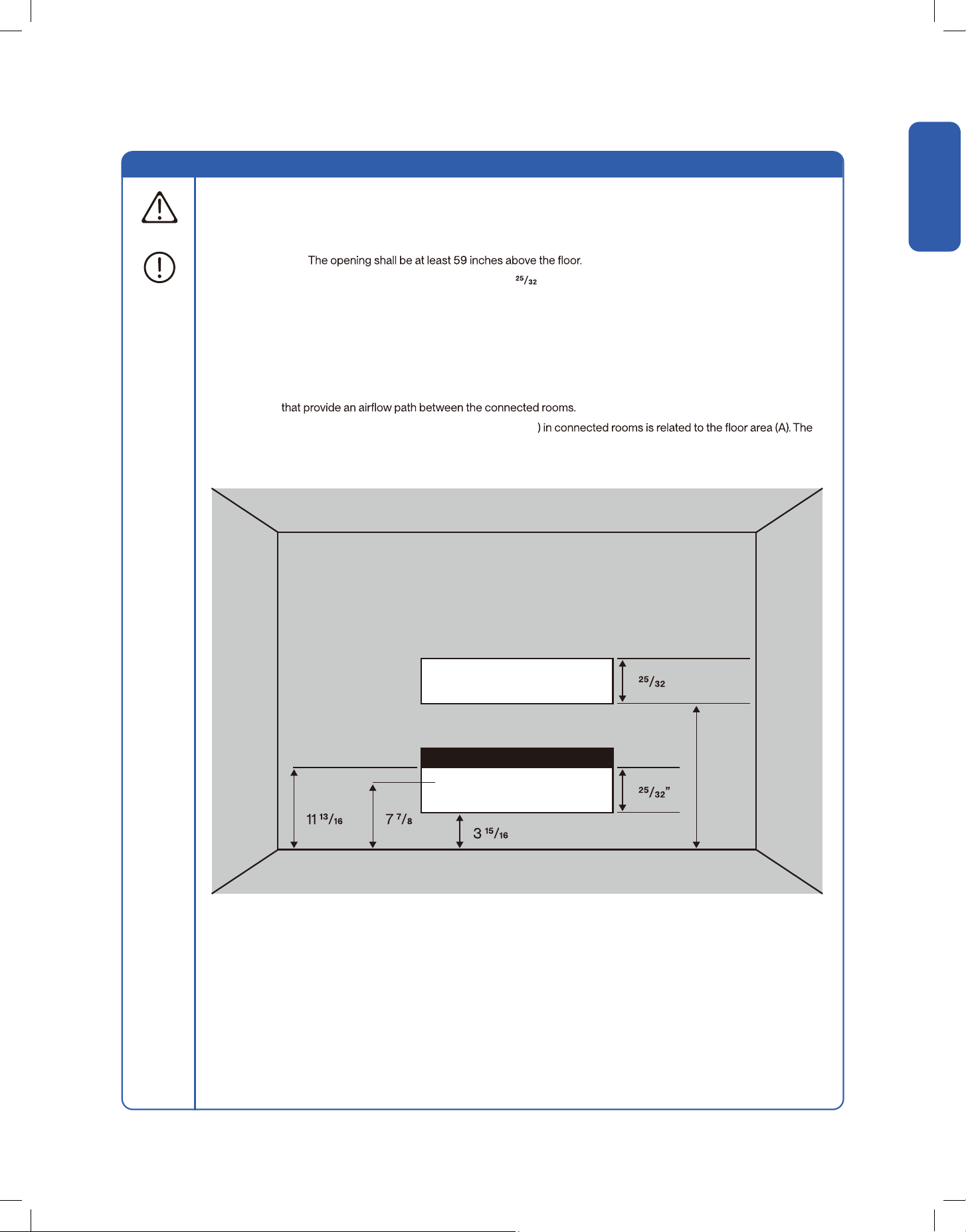
1. The opening shall not be less than Anv
min in [Table 1-1].
2. The area of any opening above
compliance with Anvmin.
3. At least 50% of the opening area of Anv
min shall be below
4. The bottom of the opening is not more than
5. The opening is a permanent opening that cannot be closed.
6.
inches above the surface of the
• Low level opening:
•
partitions and doors of the space in which the appliance is installed.
• Space connected by only drop ceilings, ductwork, or similar connections shall not be considered as a single
• Rooms on the same oor and connected by an open passageway between the space can be considered a
single room when determining compliance to A
min, if the passageway complies with all the followings:
•
room when determining compliance to Amin, provided all of the following conditions are met as [Fig 1-1].
•
min to install an appliance with refrigerange Mc (kg) shall be in accordance with:
• Room area calculation requirements:
• M
max = SF x LFL x h
• The space considered shall be any space which contains refrigerant-containing parts or into which refrigerant
refrigerant.
•
• Amin = Mc / (SF x LFL x h
5
v.20251118C
Before Installation
Before Installation
Warning and Safety
Additional Information About R454B Refrigerant
WARNING
1. The opening shall not be less than 50% of Anvmin in [Table 1-2].
2. The opening is a permanent opening that cannot be closed.
3.
4. The height of the opening is not less than inches.
1. The room into which refrigerant can leak, plus the connected adjacent room(s) shall have a total area not
less than A
min. Amin is shows in [Table 1-4].
2. The room area in which the unit is installed shall not be less than 20% A
min. Amin is shows in [Table 1-4].
• High level opening:
• Room size requirement:
• The requirement for the second opening can be met by drop ceiling ventilation ducts, or similar arrangements
• The minimum opening for natural ventilation (Anvmin
actual refrigerant charge in the system (Mc), and the allowable maximum refrigerant charge in the system
(M
max). Anvmin can be determined according to [Table 1-2].
Fig 1-1 Opening Requirement for Connected Rooms
≥ ”
≥ 59”
≥
”
≥ 50% of Anv
min
≥ 50% of Anvmin
≥ ”≥ ”
≥
6
Before Installation
Before Installation
Warning and Safety
Additional Information About R454B Refrigerant
WARNING
A (sq. ft) Mc (lb oz) Mmax (lb oz) Anvmin (sq ft)
40 9lb 9oz 2lb 10oz 0.9
50 9lb 9oz 3lb 5oz 0.8
60 9lb 9oz 4lb 0oz 0.7
70 9lb 9oz 4lb 10oz 0.6
80 9lb 9oz 5lb 5oz 0.6
90 9lb 9oz 6lb 0oz 0.5
100 9lb 9oz 6lb 10oz 0.4
110 9lb 9oz 7lb 5oz 0.3
120 9lb 9oz 8lb 0oz 0.2
130 9lb 9oz 8lb 10oz 0.2
140 9lb 9oz 9lb 5oz 0.1
150 9lb 9oz 10lb 0oz 0.0
160 9lb 9oz 10lb 10oz 0.0
A / TA (sq. ft) Mmax (lb oz)
40 2lb 10oz
50 3lb 5oz
60 4lb 0oz
70 4lb 10oz
80 5lb 5oz
90 6lb 0oz
100 6lb 10oz
110 7lb 5oz
120 8lb 0oz
130 8lb 10oz
140 9lb 5oz
150 10lb 0oz
A / TA (sq. ft) Mmax (lb oz)
160 10lb 10oz
170 11lb 5oz
180 12lb 0oz
190 12lb 10oz
200 13lb 5oz
210 14lb 0oz
220 14lb 10oz
230 15lb 5oz
240 16lb 0oz
250 16lb 10oz
260 17lb 5oz
Table 1-2 The Minimum Opening Area for Connected Rooms
Table 1-3 The Allowable Maximum Refrigerant Charge
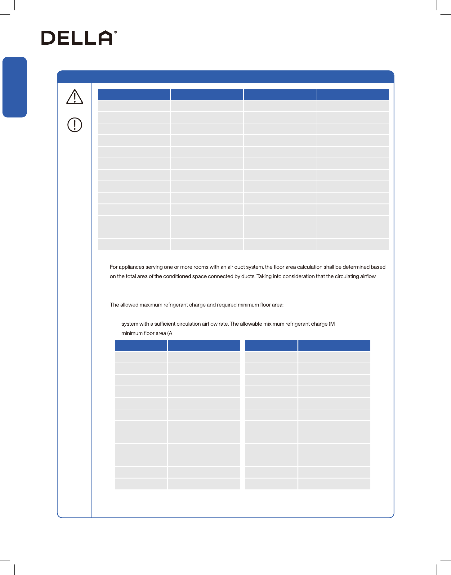
•
distributed to all the rooms by the appliance integral indoor fan will mix and dilute the leaking refrigerant before entering
any room.
•
• If the fan incorporated to an appliance is continuously operated or operation is initiated by a refrigerant detection
max) and the required
min / TAmin) is shown in [Table 1-3] and [Table 1-4]
7
v.20251118C

Before Installation
Before Installation
Warning and Safety
Additional Information About R454B Refrigerant
WARNING
Mc (lb oz) Amin / TAmin (sq. ft)
4lb 6oz 66.1
4lb 13oz 72.7
5lb 4oz 79.3
5lb 11oz 86.0
6lb 2oz 92.6
6lb 9oz 99.2
7lb 0oz 105.8
7lb 7oz 112.4
7lb 15oz 119.0
8lb 6oz 125.6
8lb 13oz 132.2
9lb 4oz 138.8
9lb 11oz 145.5
10lb 2oz 152.1
10lb 9oz 158.7
Mc (lb oz) Qmin (CFM)
4lb 6oz 119
4lb 13oz 131
5lb 4oz 143
5lb 11oz 155
6lb 2oz 167
6lb 9oz 179
7lb 0oz 191
7lb 7oz 203
7lb 15oz 215
8lb 6oz 227
8lb 13oz 239
9lb 4oz 251
9lb 11oz 263
10lb 2oz 275
10lb 9oz 287
Mc (lb oz) Amin / TAmin (sq. ft)
11lb 0oz 165.3
11lb 7oz 171.9
11lb 14oz 178.5
12lb 5oz 185.1
12lb 12oz 191.7
13lb 3oz 198.4
13lb 10oz 205.0
14lb 1oz 211.6
14lb 8oz 218.2
14lb 15oz 224.8
15lb 6oz 231.4
15lb 14oz 238.0
16lb 5oz 244.6
16lb 12oz 251.2
17lb 3oz 257.9
Mc (lb oz) Qmin (CFM)
11lb 0oz 298
11lb 7oz 310
11lb 14oz 322
12lb 5oz 334
12lb 12oz 346
13lb 3oz 358
13lb 10oz 370
14lb 1oz 382
14lb 8oz 394
14lb 15oz 405
15lb 6oz 418
15lb 14oz 430
16lb 5oz 442
16lb 12oz 454
17lb 3oz 466
Table 1-4 The Required Minimum Floor Area
Table 1-4 The Required Minimum Floor Area
8
Before Installation
Before Installation
Warning and Safety
Additional Information About R454B Refrigerant
WARNING
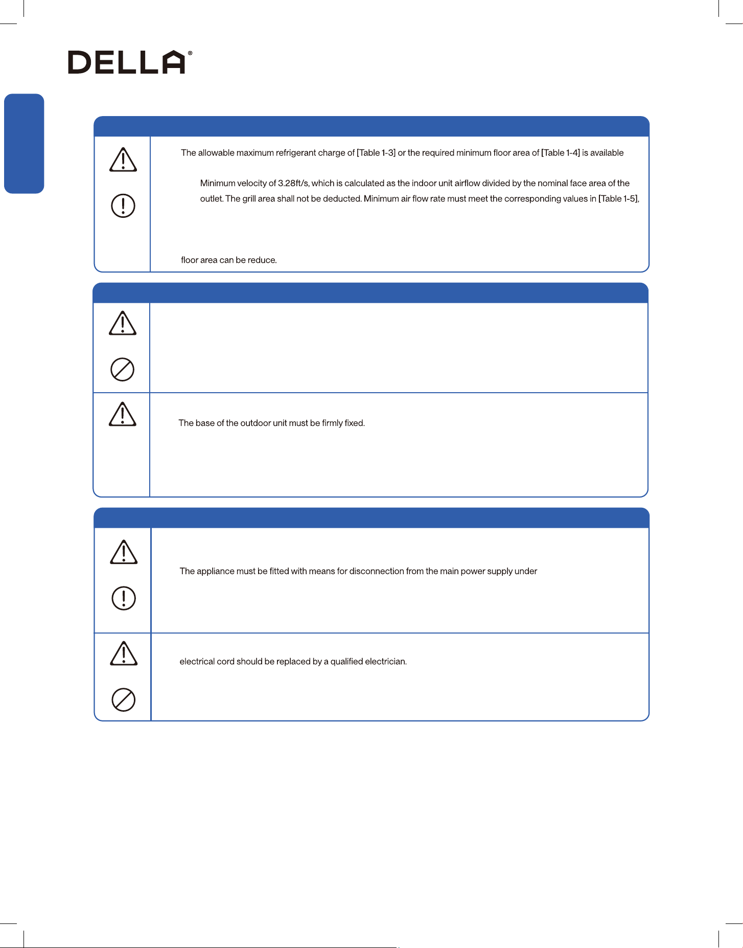
•
only if the following conditions are met:
• The maximum refrigerant limit described above applies to unventilated areas. If additional measures such as mechanical
ventilation or natural ventilation are implemented, the maximum refrigerant charge can be increased or the minimum
•
which is related to the actual refrigerant charge of the system (Mc).
About Installation
• Do not alter, change, or modify the appliance.
• Prevent children from accessing the work area during installation to prevent unforeseeable accident.
•
• Carry out a test run after the installation.
• The packaging materials are recyclable and should be disposed of in a separate waste bins.
• The appliance should not be installed in a location where the air outlet of the indoor or outdoor unit is obstructed.
Obstruction of these opening may cause damage or malfunctions to the appliance.
WARNING
CAUTION
About Power and Electricity
• Ensure that the power voltage corresponds to that stamped on the rating plate.
• A fuse or overload protection device with a suitable capacity be installed.
•
over-voltage category III conditions. All electrical wiring must follow federal, state, or local regulations.
• When working on the electric terminals, ensure the appliance is disconnected from the power supply.
• Make sure the appliance is properly grounded to prevent electric shock.
• Do not bend, tug, or compress the power cord during installation to prevent damaging the power cord. Damaged
WARNING
WARNING
9
v.20251118C
Before Installation
Before Installation
Warning and Safety
About Operation
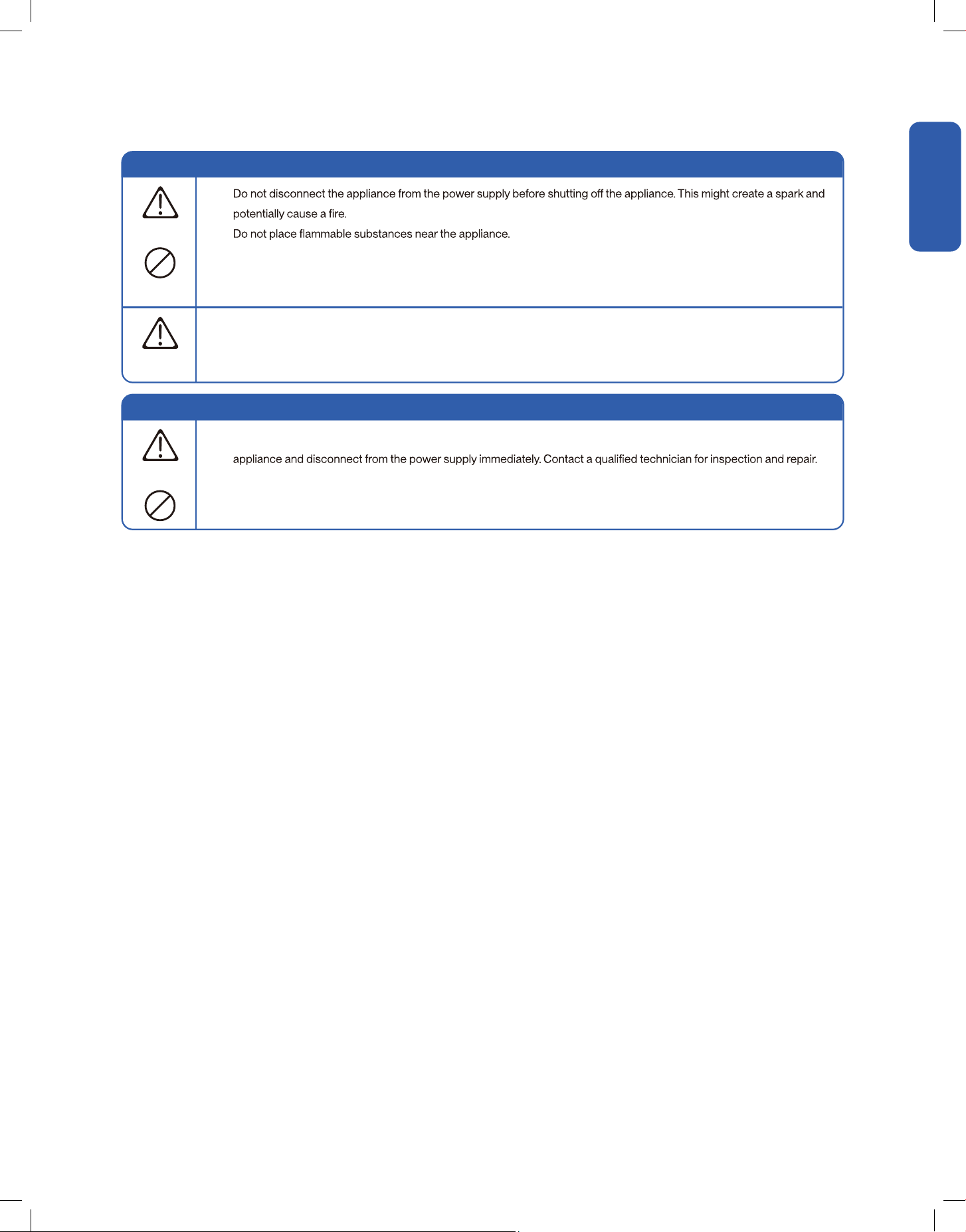
•
•
• Do not climb onto or place any objects on the appliance.
• Do not insert any objects into the appliance to prevent damage or injury.
• Do not obstruct the air inlet or outlet.
• Only use the appliance as instructed in this booklet. These instructions are not intended to cover every possible
condition and situation. As with any electrical household appliance, common sense and caution are therefore always
recommended for usage and maintenance.
WARNING
CAUTION
Encountering Troubles
• In the case of the appliance emitting smoke, burning smell, leaking water, or making unusual noise, shut down the
WARNING
10
Installation
Installation
• Ensure air optimal distribution for the air handler.
• Air path should not be blocked or obstructed.
• Make sure condensation from the air handler can be drain properly.
• Ensure there is sucient clearance around the unit as stated below, and for future maintenance and servicing.
• Keep the refrigerant lineset within allowable limit between the outdoor compressor and indoor air handler.
• Avoid installing the air handler near places where oil or oil vapors may reach the unit. Oil mist or residue would collect on the heat exchanger
and reducing the air handler performance.
Installation Info
Installation Location
Refrigerant Port
Refrigerant Port
Drain Port
Drain Port
≥25"
≥25"
≥40"
≥40"
Vertical Application Horizontal Application
11
v.20251118C
Installation
Installation
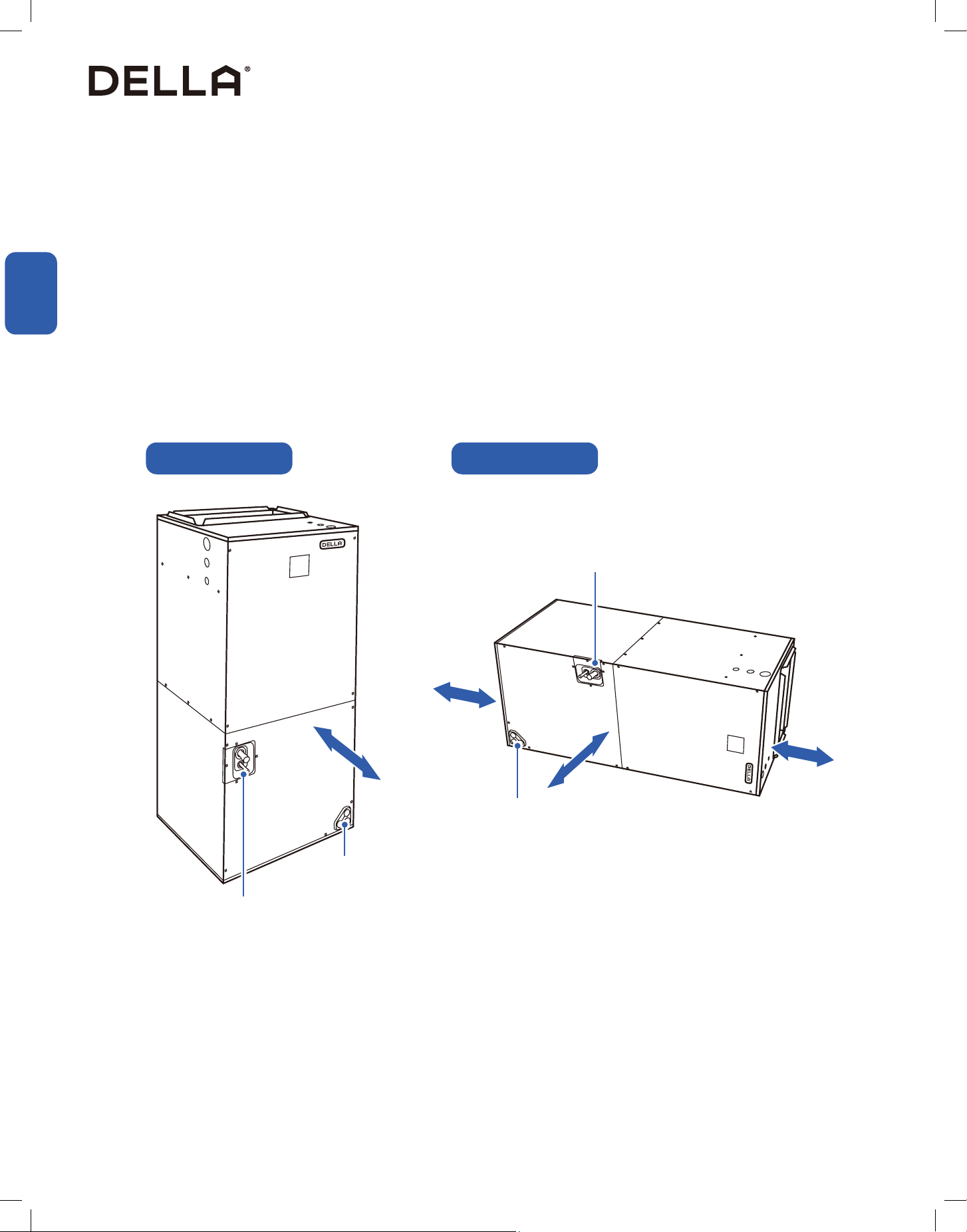
This air handler is designed for indoor installation only.
The air handler can be install in either vertical upright position and horizontal position.
In the case of choosing to install the air handler in a horizontal position, a minor eld modication is necessary to covert from "horizontal right" to
horizontal left"
Installation Info
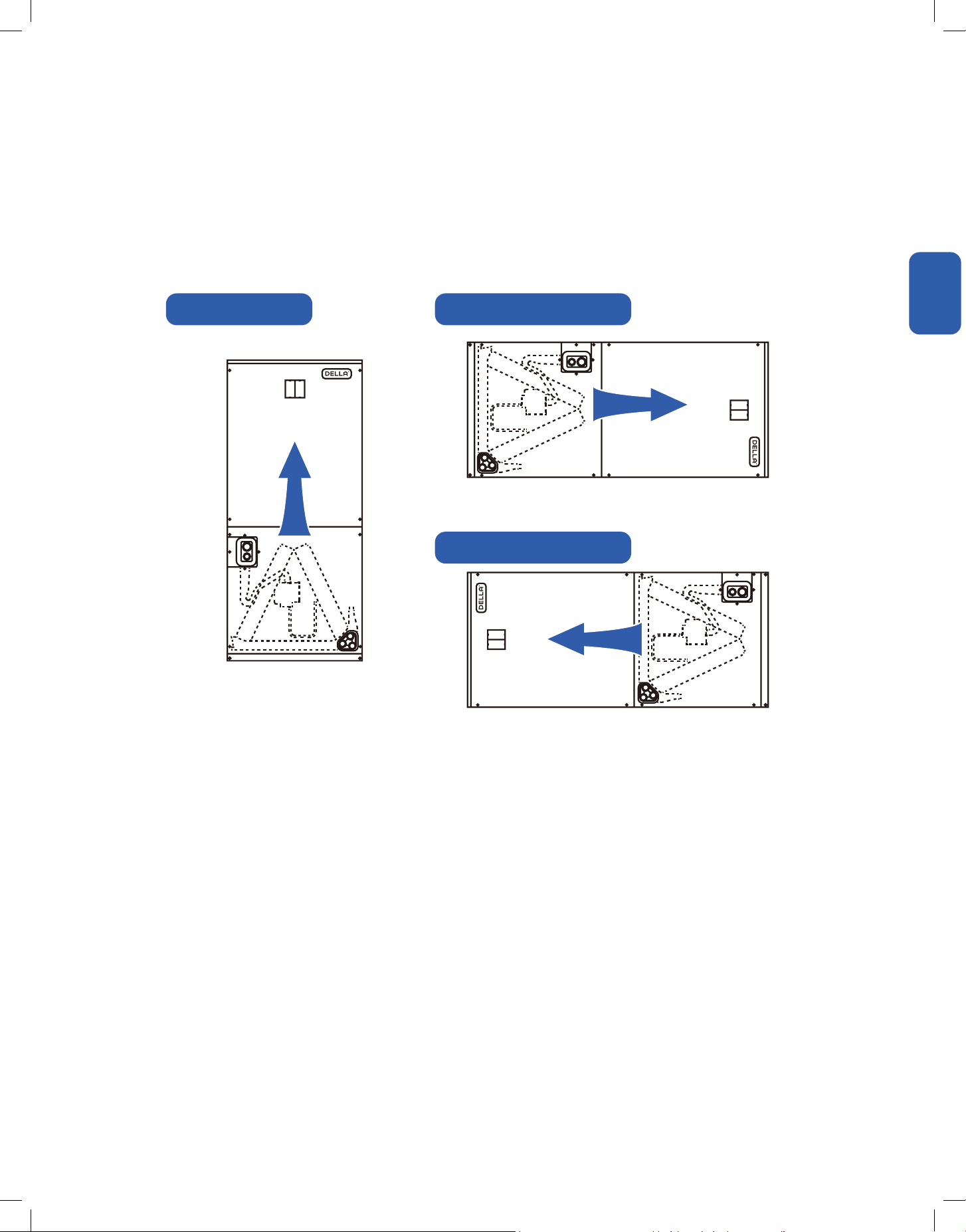
Choosing Appliance Orientation
Upow Conguration Horizontal Right Conguration
Horizontal Left Conguration
Air Flow
Air Flow
Air Flow
12
Installation
Installation
Installation Info
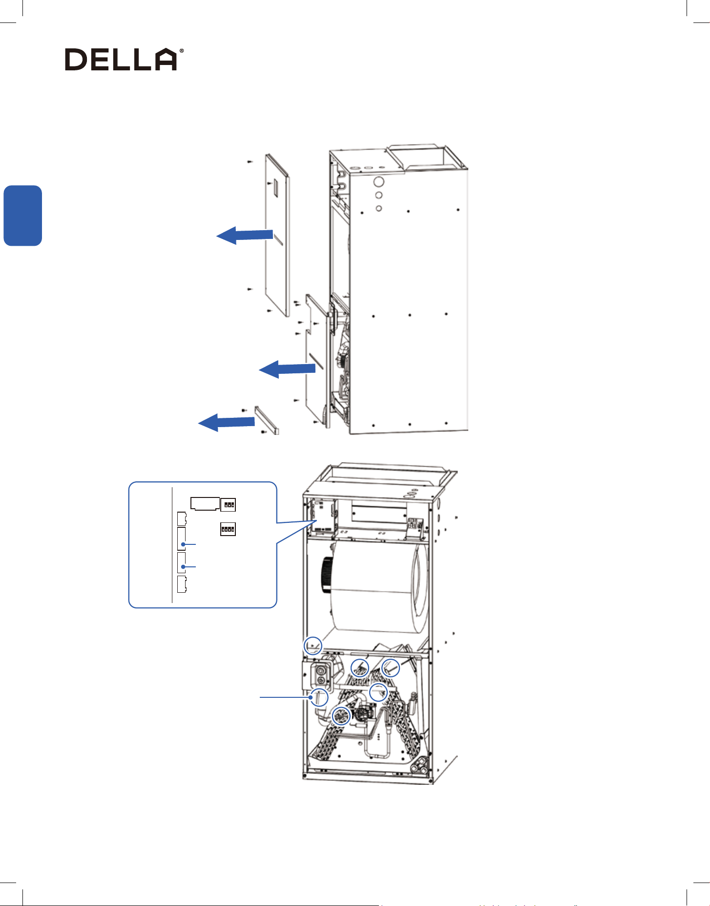
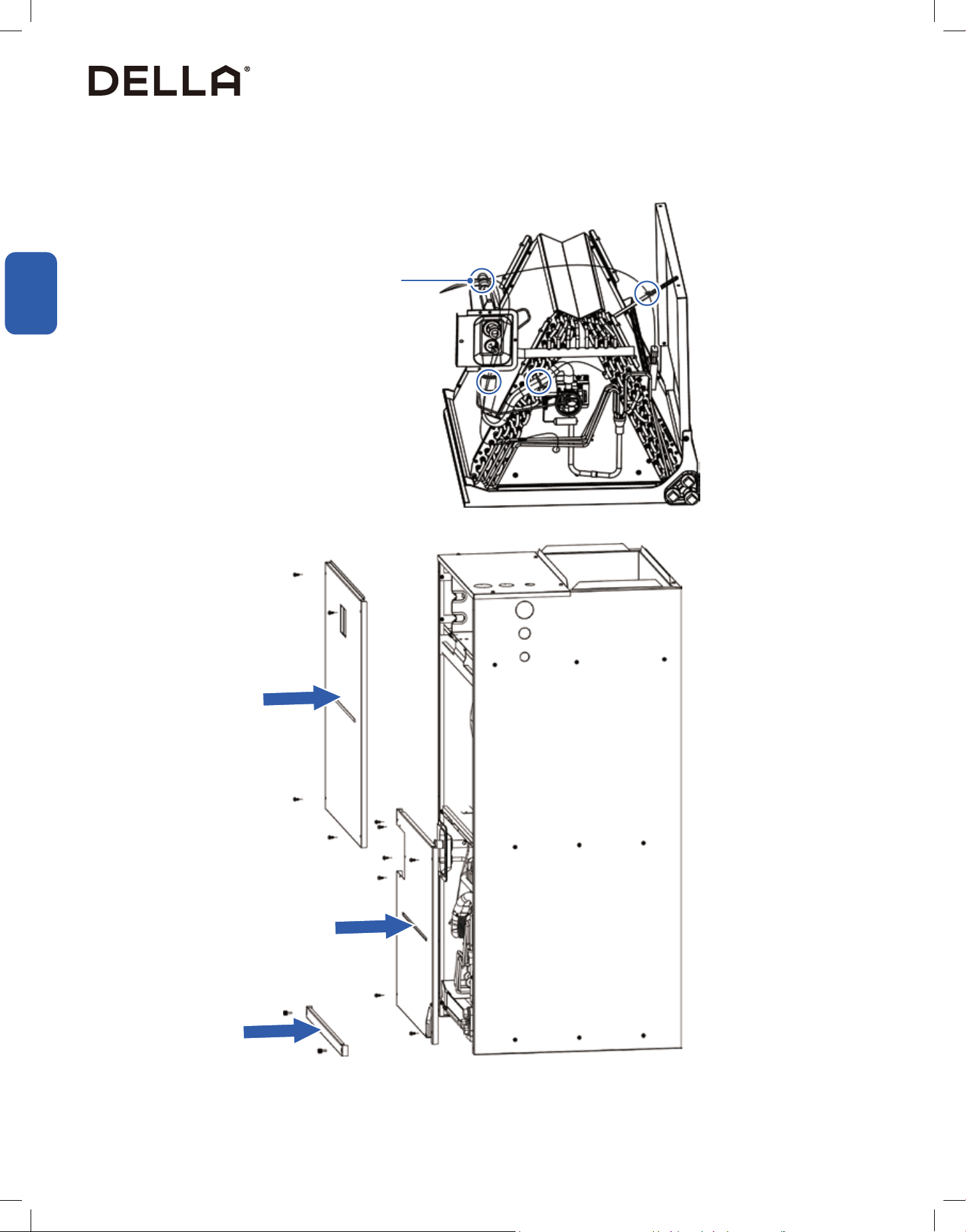
Horizontal Left Orientation Modication
1
2
3
CN17
Remove Cable Times
Unplug Cable from CN17, CN18
CN18
• Remove front panels from the air handler in the order stated on the above graphic.
• Unplug the cable connectors of the evaporator from the circuit board.
13
v.20251118C
Installation
Installation
Installation Info
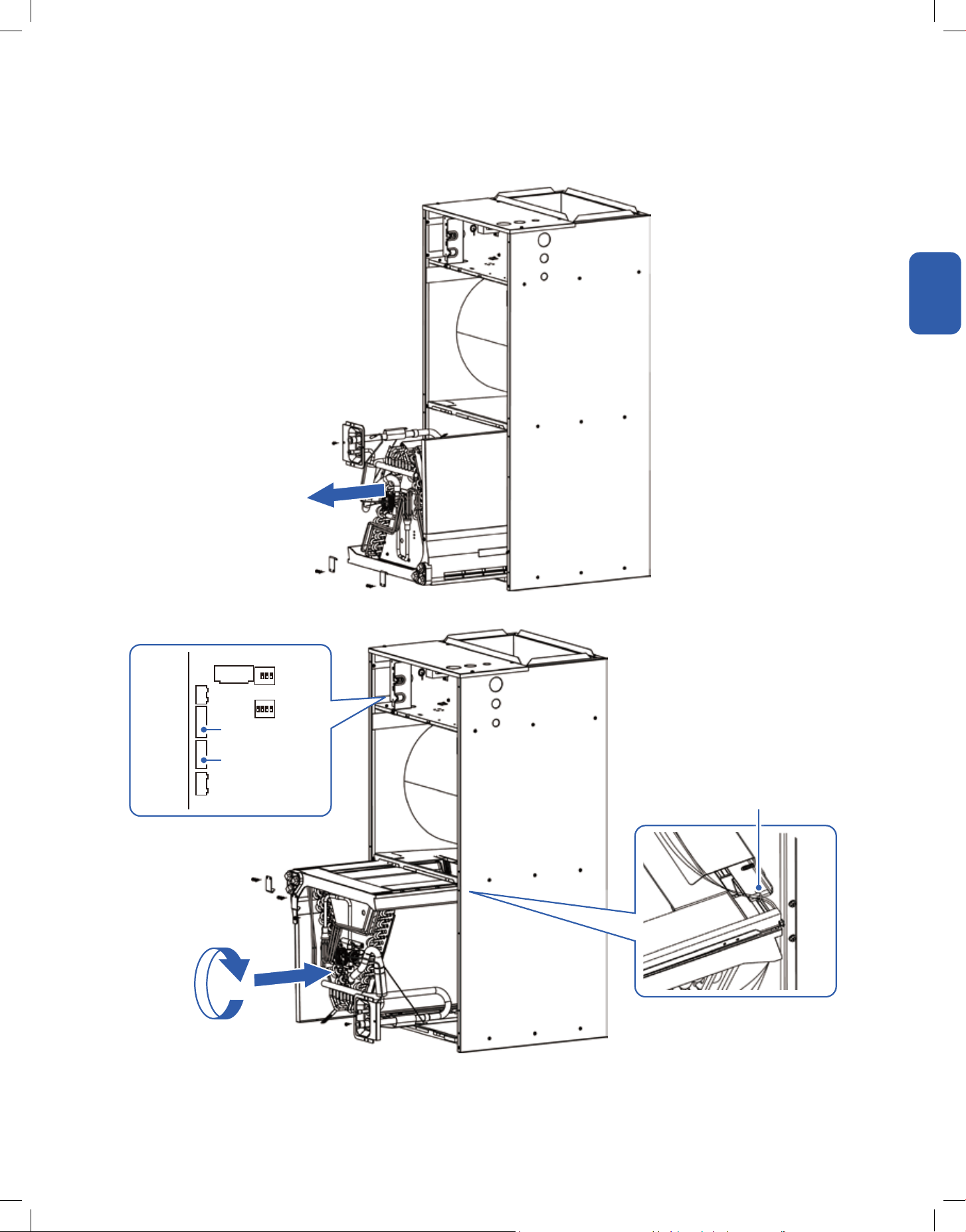
Horizontal Left Orientation Modication
Wire Hook
• Slide the evaporator out from the air handler unit cabinet.
• Rotate the evaporator upside down and slide it back into the air handler unit cabinet. Pass wire cable through the water receiving tray and
manage the wires to the hook, then reconnect the cable to the circuit board.
CN17
Reconnect Cable to CN17, CN18
CN18
1
2
14
Installation
Installation
Installation Info
Horizontal Left Orientation Modication
Secure cable and sensors
• Use cable ties to secure cables in indicated place.
• Reinstall all the front cover plates to the unit.
1
2
3
15
v.20251118C
Installation
Installation
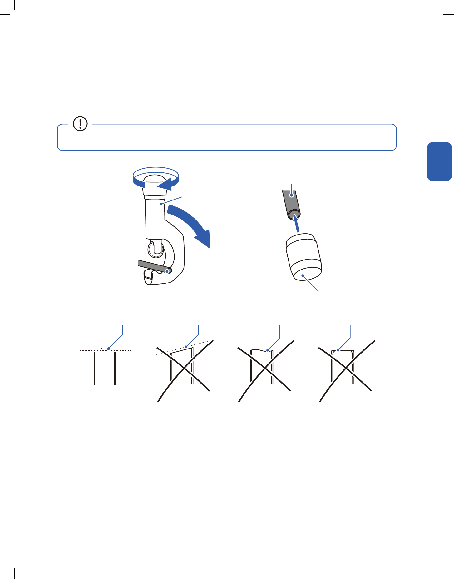
Cut new or existing refrigerant line to your desired lenghth.
Cutting the Refrigerant Pipe
1. Cut the copper pipe with a pipe cutter.
2. Remove any burrs or rough edges with a reamer with the pipe facing downward.
Refrigerant Pipe
Clean and Perpendicular Cut Slanted Cut Uneven Cut Rough Edge / Burr
Pipe Cutter
Refrigerant Pipe
(Must face downward)
Reamer
• The opening of the pipe must face downward to the ground when deburring to prevent chips or dust from entering the pipe.
Installation Info
16
Installation
Installation
To Outdoor Unit
Installation Info
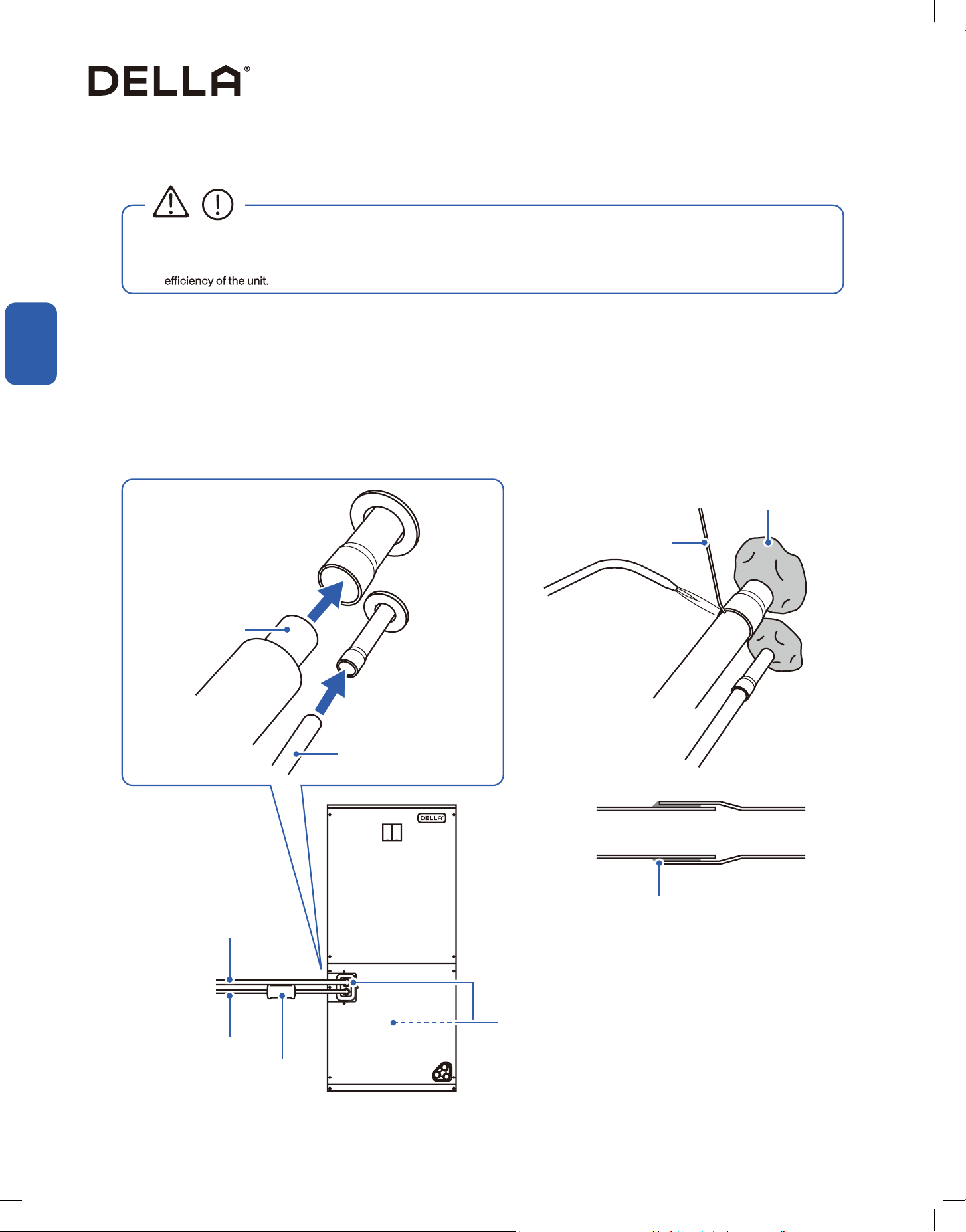
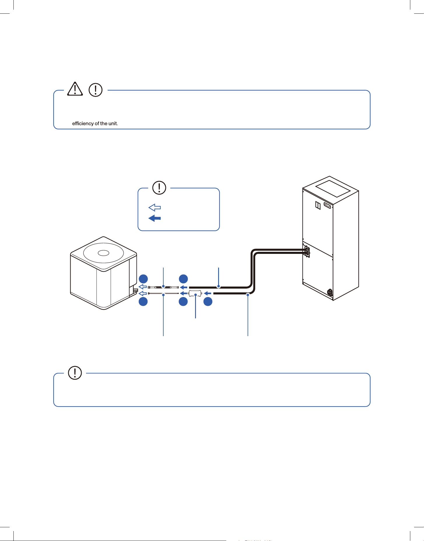
Refrigerant Line Connection and Brazing
• Do not install the connecting refrigerant pipe unitl both outdoor compressor and indoor air handler units have been installed.
• Handle the refrigerant pipe with care, any damage, dent, or deform on the pipe would cause refrigerant leak and drastically reduce
CAUTION
Suction Line
Suction Line
Liquid Line
Liquid Line
Bi-directional lter drier
Brazing Alloy
Heat Blocking Putty
Place heat blocking putty around thermal expansion
valve and temperature sensor before brazing
1. Remove cover caps on the refrigerant ports on the air handler.
2. Cover thermal expansion valve and temperature sensors with heat blocking putty.
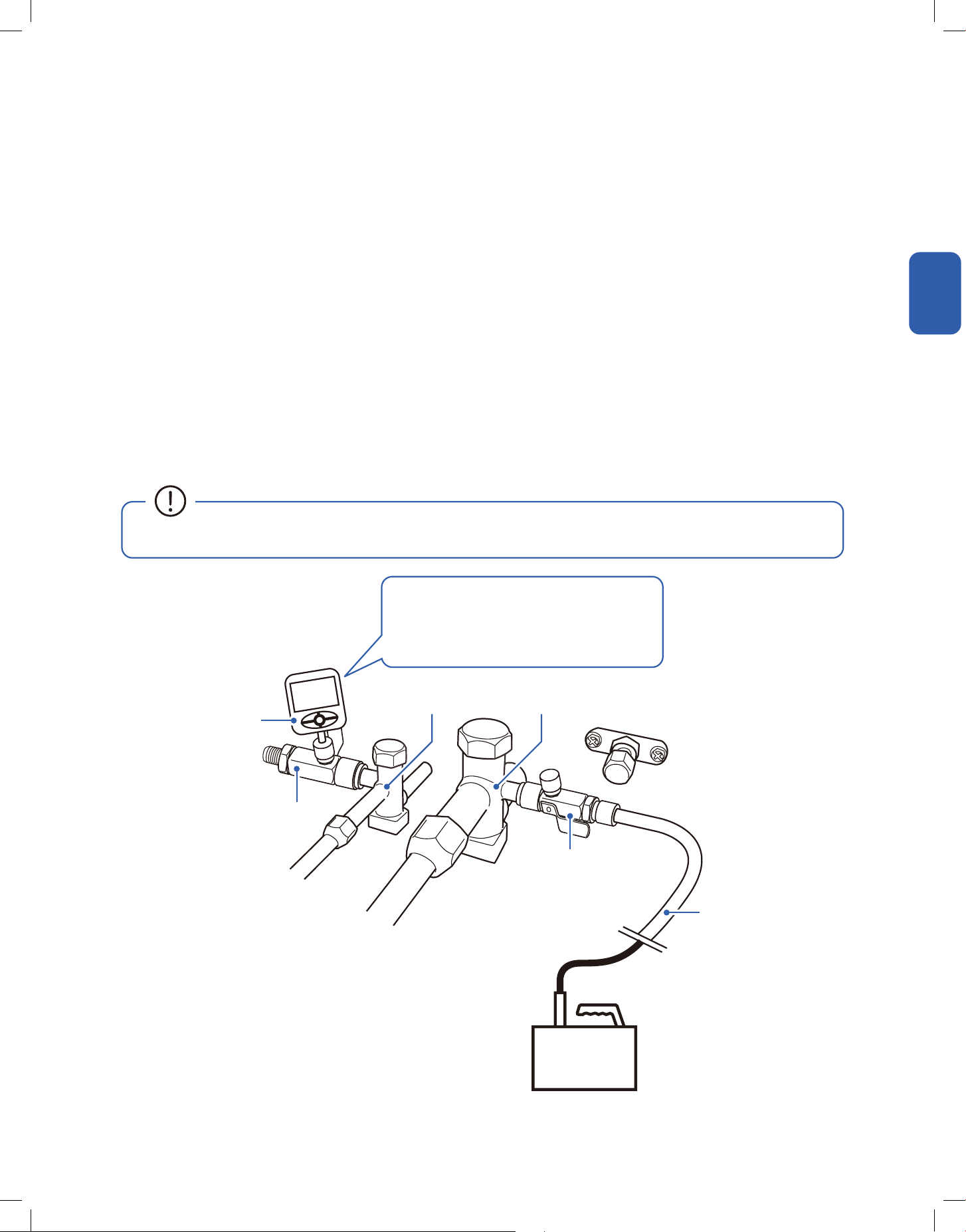
3. Purge refrigerant lines with dry nitrogen from gas service valve.
4. Connect refrigerant lines to the indoor unit's refrigerant ports.
5. A bi-direction lter drier (without active alumina) should be connected to the liquid line.
6. Braze all the connections.
7. Remove heat blocking putty only after the braze work is completed and the connections are cooled down.
Let capillary action draws in the brazing material into the connection
17
v.20251118C
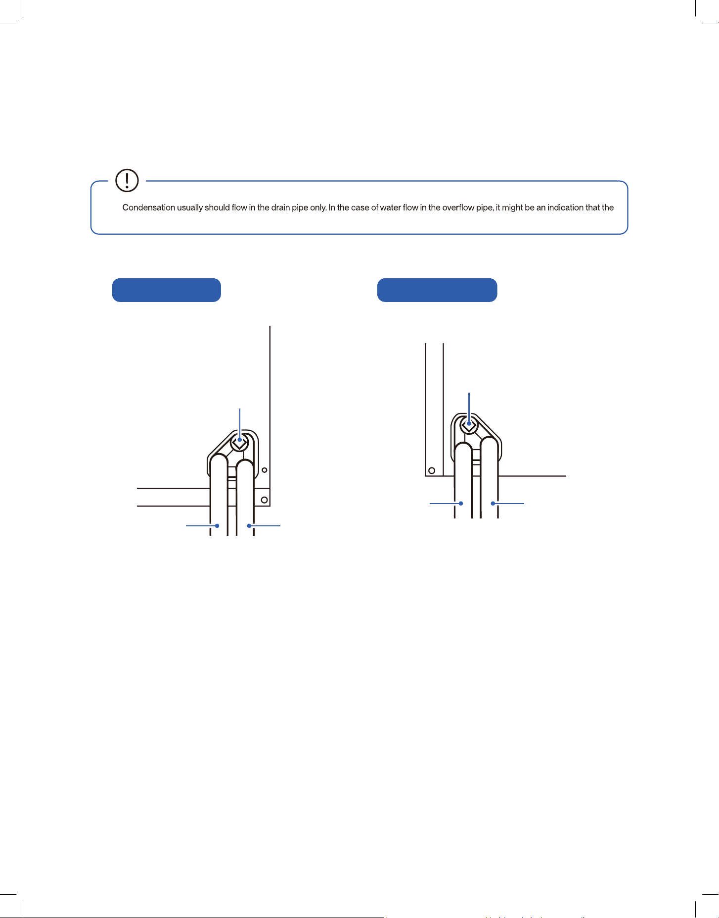
Drain Pipe Connection
Installation Info
• When connecting drain pipe, make sure the upper most drain port is always covered, the lowest port should be connected to a drain pipe,
and the remaining port connected to a overow pipe that is exposed to the air.
•
drain pipe is clogged or obstructed.
Upow Conguration Horizontal Conguration
Block o
Block o
Drain Pipe
Drain Pipe
Overow Pipe
Overow Pipe
18
Installation
Installation
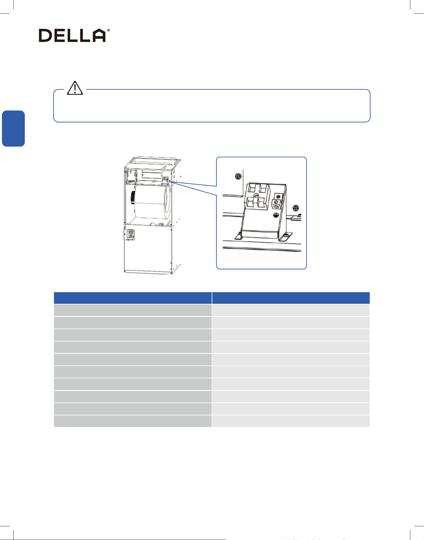
Electrical Wiring
Installation Info
• Follow all electrical safety precausions when installing, testing, servicing, and troubleshooting this product. Failing to follow precautions
when working with live electrical components could result in death or serious injury.
WARNING
The power supply must corresponds to that stamped on the rating plate.
Power wiring must comply with national, state, and local codes.
Locate and follow the wiring diagram printed on the inside of the control box cover.
Wiring Reference
The ampacity shown apply to appliance wiring materials with insulation rated not less than 194°F / 90°C.
Supply circuit power wiring must be 167°F minimum copper conductors only.
Wiring Material Ampacity AWG
4 22
7 20
10 18
13 16
18 14
25 12
30 10
40 8
55 6
70 4
19
v.20251118C
Installation
Installation
Installation Info
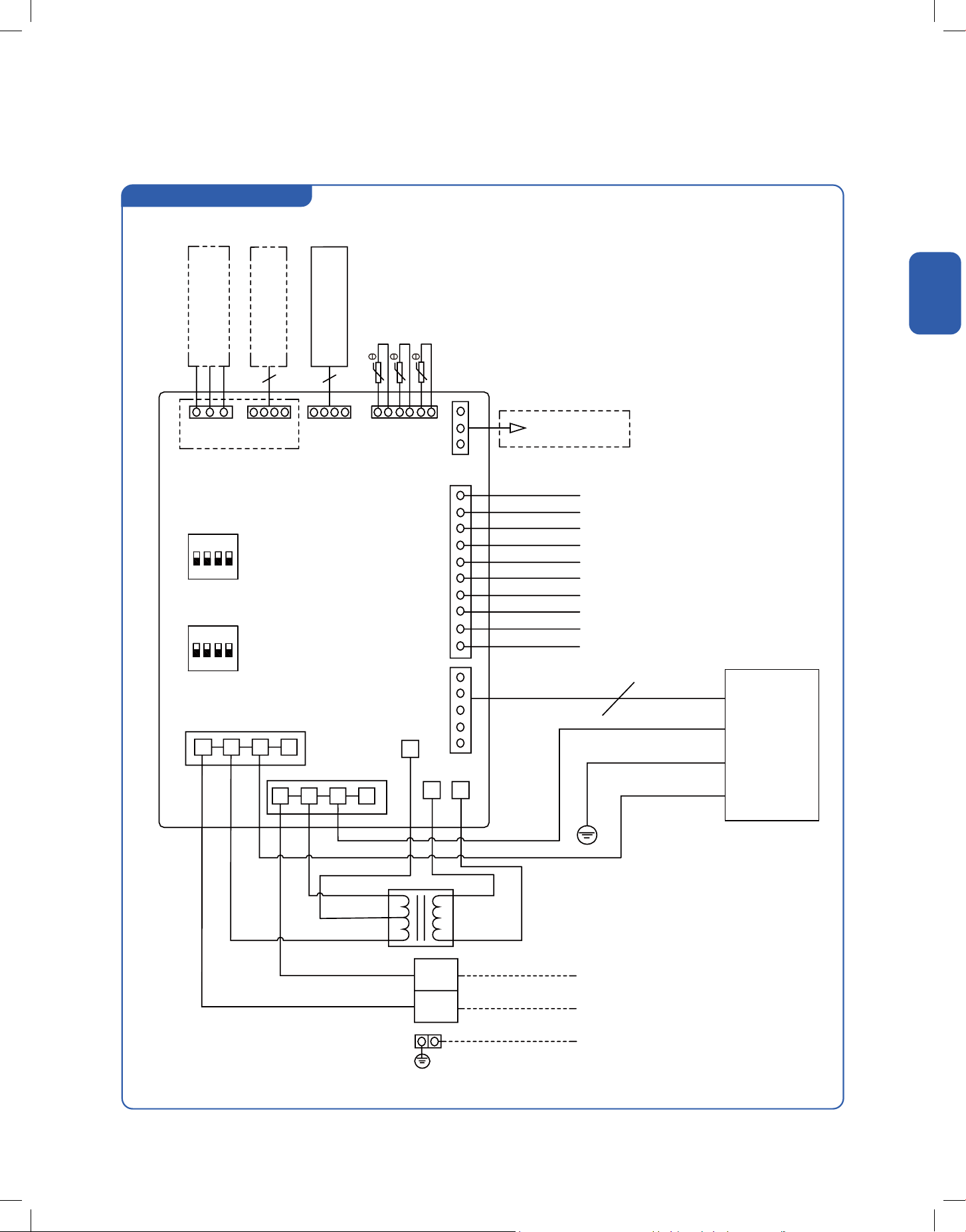
Circuit Diagram
048-T series IDU
Fan Motor
Heater Kit Plug
Power Supply
Ground
(Optional)
PCB
L1
CN5
CN10 CN11
CN16
CN14
CN19
CN18CN17CN12CN13
A
To Outdoor
RS485
Wired Remote
Controller
Refrigerant
Leakage Sensor
Room Temperature Sensor
Tube Temperature Sensor
Supply Air Temperature Sensor
B
GND
L1
R
C
G
Y1
Y2
O
W1
W2
D
Yo
Red
Blue
Green
Yellow
Yellow & Red
Orange
Black
White
Purple
Gray
L2
L2
SW1
SW2
1
1
2
2
3
3
4
4
Default
Default
Red
Red
Red
White
Blue / 208V
Yellow & Green
Black / 240V
Black
Yellow
Transformer
Black
20
Installation
Installation
Installation Info
Low Voltage Wire Connection
Grounding
Class 2 low voltage wiring should not be run in conduit with main power wiring and must be seperated from power wiring, unless class 1 wire of
proper voltage rating is used.
• Low voltage control wiring should be color coded 18 AWG.
• Refer to wiring diagrams attached to indoor and outdoor sections to be connected.
• Make sure separation of control wiring and power wiring has been maintained.
• Be sure power supply corresponds to that on the equipment's rating plate.
• Power and grounding wiring must comply with local codes.
• Low voltage wiring to be No. 18 AWG minimum conductor
• Some thermostats may use W2/AUX for heat pump.
• The electrical heater may not be avaliable for some model.
• For single stage thermostat with Y/Y1 terminal only, place both Y1 and Y2 wire together to Y/Y1 terminal.
• When the communication method between the indoor and outdoor unit is selected as 24v communication, the above wiring method is
required.
• Grounding may be accomplished
by grounding metal conduit when installed in accordance with electrical codes to the unit cabinet.
Grounding may also be accormplised by attaching ground wire(s) to ground lug(s) provided in the unit wiring compartment.
• Use of multiple supply circuits require grounding of each circuit to lug(s) provided in the unit.
Unit Terminal Control Wiring
R 24V AC Power Supply for Thermostat from Secondary Transformer
C Common Wire
G Fan Motor Relay
Y1 Compressor Stage 1, Low Load Output Control
Y2 Compressor Stage 2, High Load Output Control
O Cooling 4-way Valve
W1 Heating Stage 1, Electrical Heater Low Load Output Control
W2 Heating Stage 2, Electrical Heater High Load Output Control
Yo Outdoor Compressor
D Defrost Signal
• The indoor unit must be grounded. Failing to follow precautions when working with live electrical components could result in death or
serious injury.
WARNING
21
v.20251118C
Installation
Installation
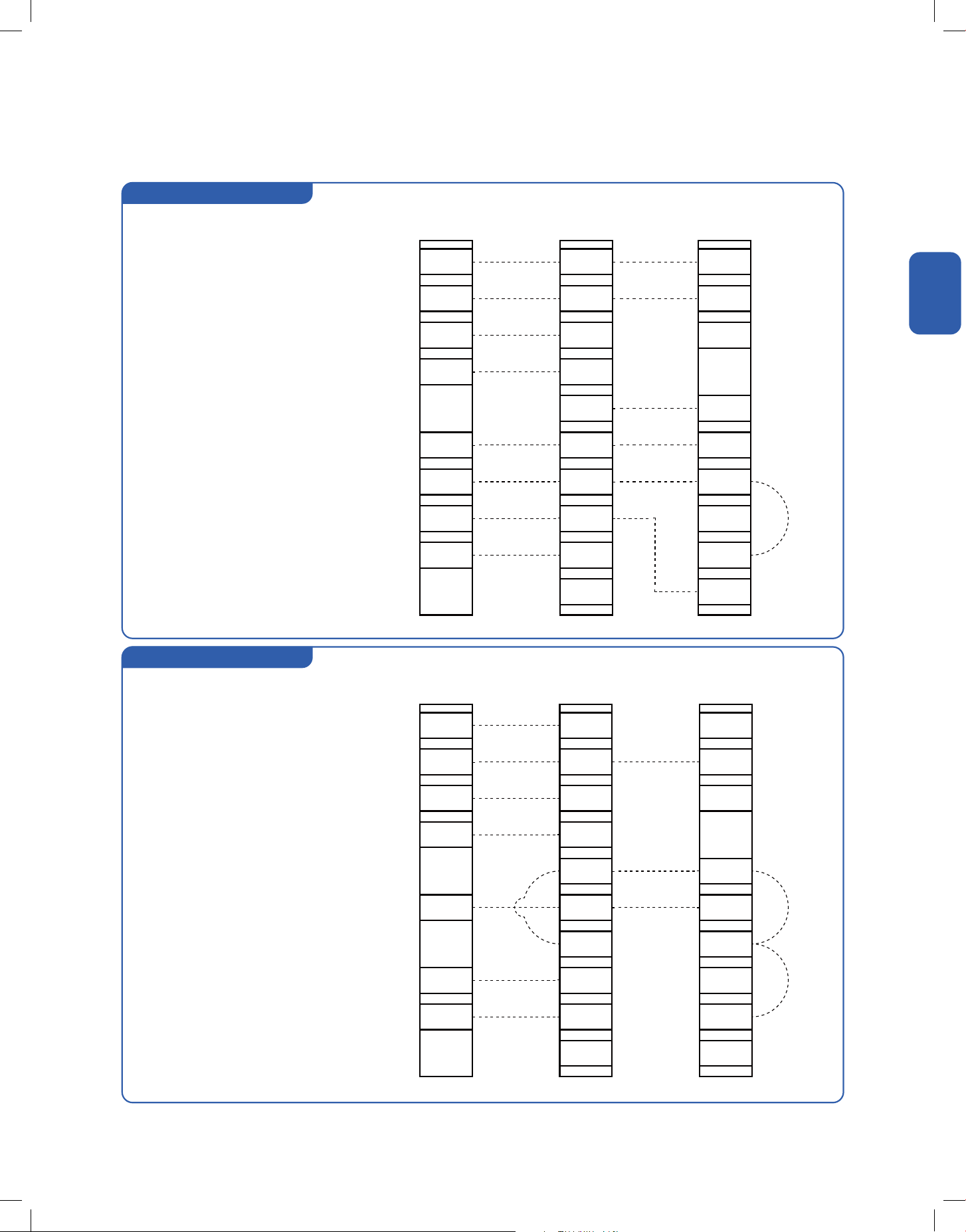
2 Stages, 2 Step, Heat Pump
2 Stages, 2 Step, Cooling Only
Thermostat
Thermostat
R
R
R
R
R
R
C
C
C
C
C
C
G
G
G
G
G
G
D
D
D
D
W2
W2
DHM
DHM
W2
W1
W1
T
T
W1
W1
W2
O
O
O
O
O
Y2
Y2
Y2
Y2
Y2
Y2
Y0
Y0
Y0
Y0
Y1
Y1
Y
Y
RED
RED
RED
RED
BLUE
BLUE
BLUE
BLUE
GREEN
GREEN
GREEN
GREEN
YELLOW
YELLOW
GRAY
GRAY
GRAY
GRAY
YELLOW&RED
YELLOW&RED
BLUE&WHITE
BLUE&WHITE
YELLOW&RED
YELLOW&RED
ORANGE
ORANGE
ORANGE
ORANGE
BLACK
BLACK
WHITE
WHITE
BROWN
BROWN
PURPLE
PURPLE
PURPLE
PURPLE
Air Handler
Air Handler
Outdoor Unit
Outdoor Unit
24V AC Hot
24V AC Hot
24V AC Common
24V AC Common
Fan
Fan
Cool / Heat 1st Stage
Cool / Heat 1st Stage
Cool / Heat 2nd Stage
Cool / Heat 2nd Stage
SOV
SOV
Emergency Heat 1st Stage /
Emergency Heat 1st Stage /
Emergency Heat 2nd Stage /
Heat 3rd Stage
Heat 4th Stage
Hea
t 4th Stage
Installation Info
Low Voltage Wire Connection
22

Installation
Installation
Single Step, Heat Pump
Single Step, Cooling Only
Installation Info
Low Voltage Wire Connection
Thermostat
Thermostat
R
R
R
R
R
R
C
C
C
C
C
C
G
G
G
G
G
G
D
D
D
D
W2
W2
DHM
DHM
W2
W2
W1
W1
T
T
W1
W1
O
O
O
O
O
O
Y2
Y2
Y2
Y2
Y0
Y0
Y0
Y0
Y1
Y1
Y
Y
RED
RED
RED
RED
BLUE
BLUE
BLUE
BLUE
GREEN
GREEN
GREEN
GREEN
YELLOW
YELLOW
GRAY
GRAY
GRAY
GRAY
YELLOW&RED
YELLOW&RED
BLUE&WHITE
BLUE&WHITE
YELLOW&RED
YELLOW&RED
ORANGE
ORANGE
ORANGE
ORANGE
BLACK
BLACK
WHITE
WHITE
BROWN
BROWN
PURPLE
PURPLE
PURPLE
PURPLE
Air Handler
Air Handler
Outdoor Unit
Outdoor Unit
24V AC Hot
24V AC Hot
24V AC Common
24V AC Common
Fan
Fan
Cool / Heat 1st Stage
Cool / Heat 1st Stage
SOV
SOV
Emergency Heat 1st Stage /
Emergency Heat 1st Stage /
Emergency Heat 2nd Stage /
Emergency Heat 2nd Stage /
Heat 3rd Stage
Heat 3rd Stage
Heat 4th Stage
Heat 4th Stage
23
v.20251118C

Installation
Installation
Installation Info
Electrical Data
048-T-24K-IDU 048-T-36K-IDU 048-T-48K-IDU 048-T-60K-IDU
Power Supply 208 V - 230 V / 60 Hz / 1P 208 V - 230 V / 60 Hz / 1P 203 V - 230 V / 60 Hz / 1P 208 V - 230 V / 60 Hz / 1P
Power Cable Diameter
Connecting to the
Terminal Block
14 AWG 14 AWG 14 AWG 14 AWG
Motor HP 1/2 1/2 3/4 3/4
Motor Step 5 5 5 5
Min. Circuit Amp 5A 5A 7A 7A
Max. Breaker Size 15A 15A 15A 15A
24
Installation
Installation
Installation Info
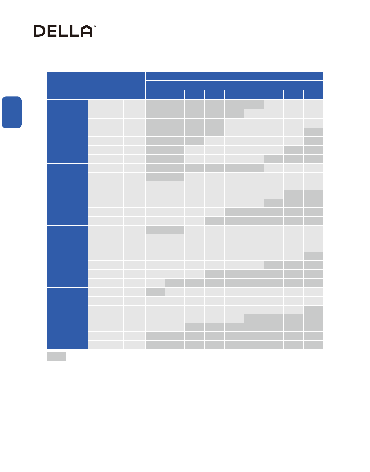
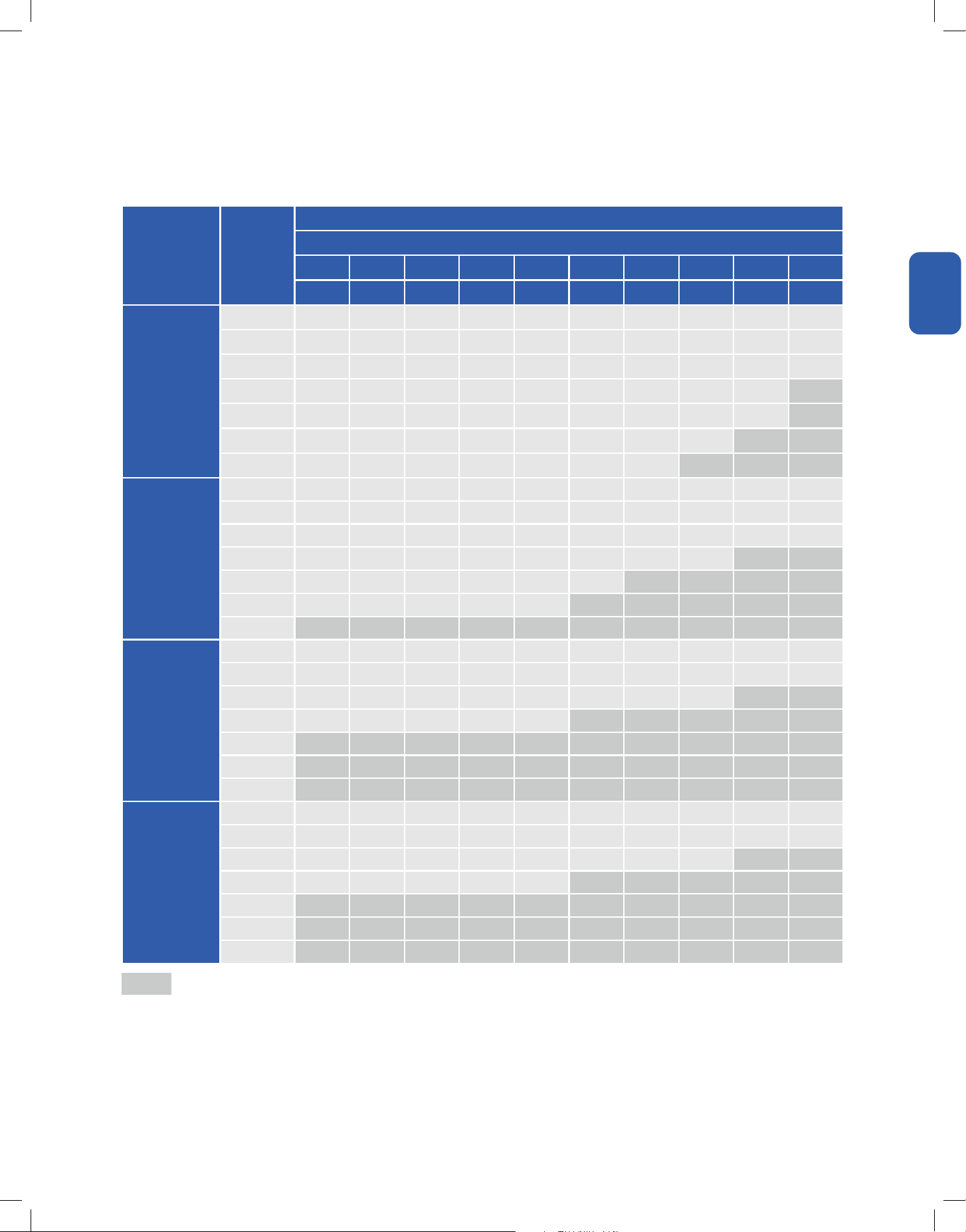
Airow Performance Data
Model Motor Speed
SCFM
External Static Pressure-Inches W.C.
0.0 0.1 0.2 0.3 0.4 0.5 0.6 0.7 0.8
048-T-24K-IDU
Super Grade SCFM 1173 1130 1065 1021 956 909 838 791 720
Top Grade SCFM 1139 1095 1028 983 916 867 795 747 675
Mid-High Grade SCFM 1105 1069 990 944 875 826 752 703 929
Mid Grade SCFM 1072 1024 953 906 835 785 709 695 583
Mid-Low Grade SCFM 1038 989 916 868 795 743 666 615 538
Low Grade SCFM 1004 954 879 829 754 702 623 571 492
Mute Grade SCFM 970 919 842 791 714 661 580 527 446
048-T-36K-IDU
Super Grade SCFM 1539 1510 1467 1438 1395 1360 1306 1271 1218
Top Grade SCFM 1440 1407 1358 1325 1276 1237 1179 1140 1082
Mid-High Grade SCFM 1340 1304 1248 1211 1156 1114 1052 1010 947
Mid Grade SCFM 1241 1200 1139 1098 1036 992 924 879 812
Mid-Low Grade SCFM 1173 1130 1065 1021 956 909 838 791 720
Low Grade SCFM 1105 1059 990 944 875 826 752 703 629
Mute Grade SCFM 1038 989 916 868 795 743 666 615 538
048-T-48K-IDU
Super Grade SCFM 1871 1836 1784 1749 1697 1654 1589 1545 1481
Top Grade SCFM 1779 1
746 1696 1663 1613 1572 1510 1469 1408
Mid-High Grade SCFM 1687 1655 1608 1577 1529 1490 1432 1393 1335
Mid Grade SCFM 1502 1474 1432 1404 1362 1327 1275 1241 1188
Mid-Low Grade SCFM 1173 1130 1065 1021 956 909 838 791 720
Low Grade SCFM 1105 1059 990 944 875 826 752 703 629
Mute Grade SCFM 1225 1184 1122 1181 1019 976 911 867 802
048-T-60K-IDU
Super Grade SCFM 2056 2017 1960 1922 1864 1817 1745 1698 1627
Top Grade SCFM 1871 1836 1784 1749 1697 1654 1589 1545 1481
Mid-High Grade SCFM 1687 1655 1608 1577 1529 1490 1432 1393 1335
Mid Grade SCFM 1502 1474 1432 1404 1362 1327 1275 1241 1188
Mid-Low Grade SCFM 1410 1377 1329 1296 1248 1210 1154 1116 1060
Low Grade SCFM 1317 1281 1225 1189 1133 1093 1032 992 931
Mute Grade SCFM 1225 1184 1122 1081 1019 976 911 867 802
Shaded boxes represent airow outside of the required 300 - 450 CFM / ton at full load.
Airow based upon cooling performance at 230V with no electric heat and no lter. Airow at 208V is approximately the same as 230V
because the multi-tap ECM motor is a constant torque motor. The torque doesn't drop o at the speed in which the motor operates.
The air distribution system has the greatest eect on airow. For this reason, the contractor should only use industry-recognized procedures to
nish ductwork.
Heat pump systems requires a specied airow. Each ton of cooling requires between 300 - 400 CFM. Duct design and constructioni should
be carefully dune. System performance can be lowered dramatically through bad planning or workmanship. Air supply diusers must be
selected and located carefully. They must be sized and positioned to deliver treated air along the perimeter of the space. Return air grilles must
be properly sized and carry air back to the blower. Failng to follow these requirement may cause abnormal noise and drafts.
*
25
v.20251118C

Installation
Installation
Installation Info
Ductwork
Ductwork must comply with the National Fire Protection Association NFPA 90A, NFPA 90B and any applicable local ordinance.
Sheet metal ductwork run in unconditioned spaces must be insulated and covered with a vapor barrier.
Fibrous ductwork may be used if constructed and installed in accordance with SMACNA construction standard on brous glass ducts. Ductwork
must comply with National Fire Protection Association as tested by U/L Standard 181 for Class I Air Ducts. Check local codes for requirements on
ductwork and insulation.
•
• Duct system must be designed within the range of external static pressure the unit is designed to operate against. It is important that the
• Design the duct system in accordance with "ACCA" Manual "D" Design for Residential Winter and Summer Air Conditioning and Equipment
Selection. Latest editions are available from: "ACCA" Air Conditioning Contractors of America, 1513 16th Street, N.W., Washington, D.C. 20036.
If duct system incorporates Xair duct, be sure that the pressure drop informaion (straight length plus all turns) shown in "ACCA" Manual "D" is
accounted for the system.
•
•
as required to prevent air leaks.
WARNING
•
•
located. Drills or sharp screw points can damage insulaiton on wires located inside unit.
26
Installation
Installation
Installation Info
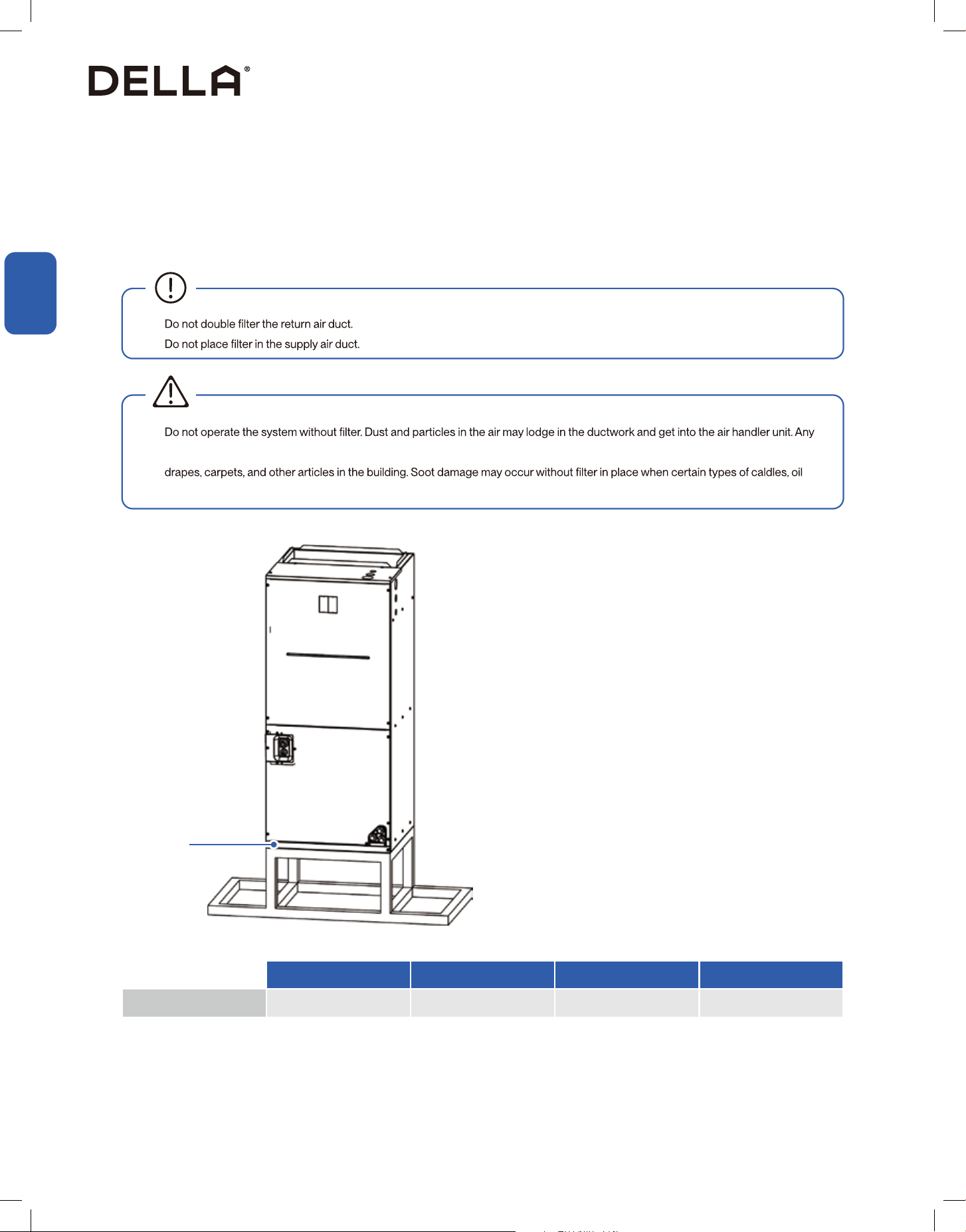
Air Filter
Filter application and replacement may aect air ow and the system performance. Reduced airow can shorten the life of the system's major
components, such as motor, heat relays, evaporator coil or compressor. Unit should be sized for a maximum of 300 feet / min. air velocity or the
recommedation of the lter type installed.
Ensure the air ow is in the range of 300 - 450 CFM if adding high eciency lters or electronic air ltration systems.
•
•
•
circulated dust particles could be heated and charred by contact with the air handler elements. This residue could soil ceilings, walls,
lamps or standing pilots are burned.
WARNING
Filter Cover
Air lter installation / replacement
1. Remove the the lter cover by unscrewing the bolts.
2. Hold the edge of the air lter and extract it from the unit.
3. Clean the air lter or use replace with a new lter.
NOTE: Air lter is not factory installed.
048-T-24K-IDU 048-T-36K-IDU 048-T-48K-IDU 048-T-60K-IDU
Filter Size 18" x 20" 18" x 20" 20" x 22" 20" x 22"
27
v.20251118C
Installation
Installation
Installation Info
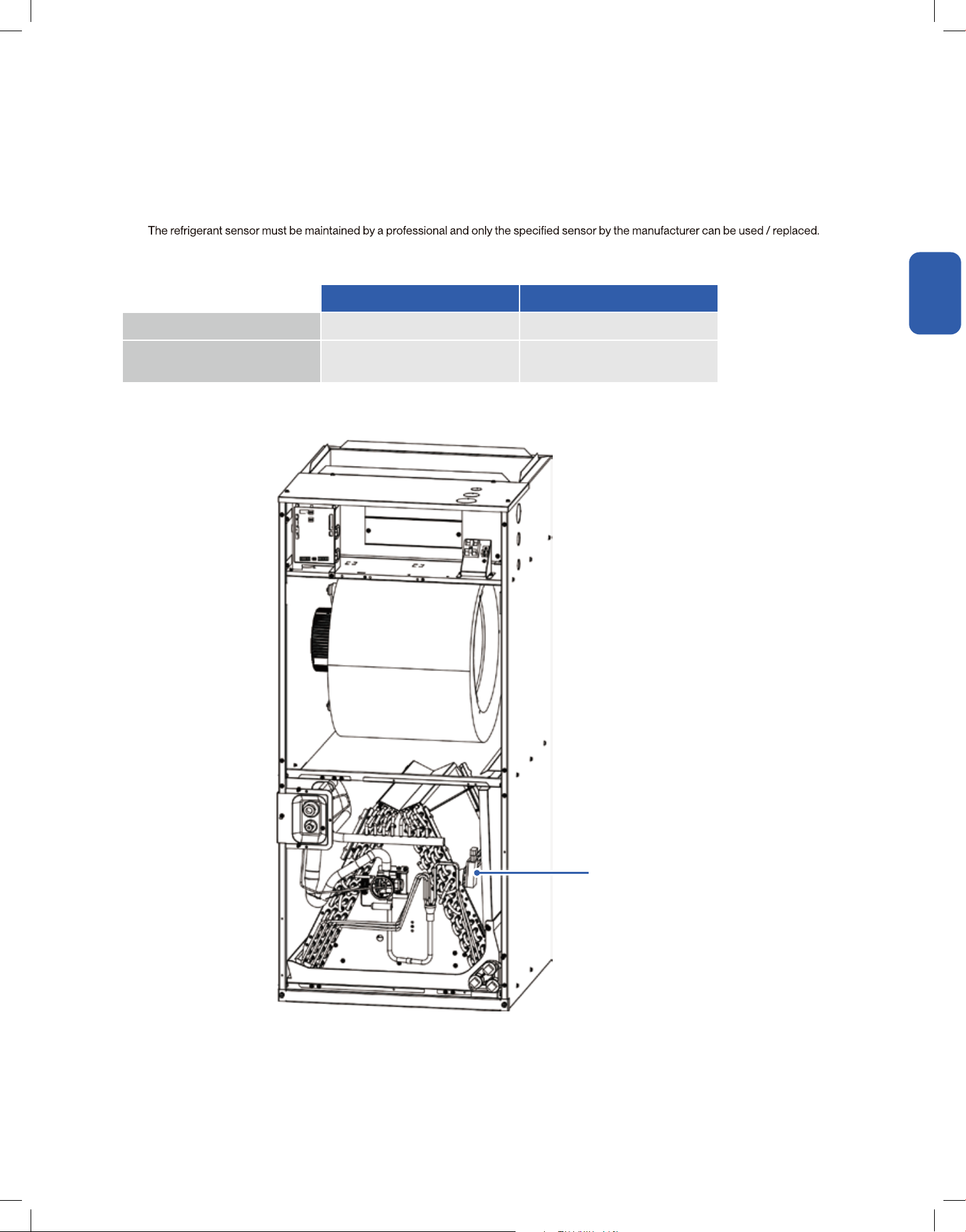
Refrigerant Sensor
The air handler is equiped with refrigerant sensor. The refrigerant sensor automatically detects the condition of the machine while in operation,
and it will automatically start air circulation and stop the compressor when the refrigerant concentration reaches an alarm range.
•
• The design lift of the refrigerant sensor is 15 years, the sensor should be replace within the range of its service life.
• When the refrigerant sensor detect abnormal level of refrigerant in the air, the alarm signal is as follows:
Refrigerant Sensor
24V communication 485 communication
Refrigerant Leak Protection Red light stays ON Display "Hd"
Abnormal communication of the
refrigerant sensor
Red light blinks Display "Fd"
28
Installation
Installation
Installation Info (Optional)
Auxiliary Heater Kit Electric Data
Air Handler Model
Heater Kit
Model
Electric Heat
(kW)
Min. Circuit Ampacity Max. Breaker (HACR) Amacity
208V 230V 240V 208V 230V 240V
048-T-24K-IDU
048-T-5KW 5 21 23 24 25 30 30
048-T-10KW 10 42 46 48 50 60 60
048-T-36K-IDU
048-T-5KW 5 21 23 24 25 30 30
048-T-10KW 10 42 46 48 50 60 60
048-T-15KW 5 + 10 21 + 42 23 + 46 24 + 48 25 + 50 30 + 60 30 + 60
048-T-48K-IDU
048-T-5KW 5 21 23 24 25 30 30
048-T-10KW 10 42 46 48 50 60 60
048-T-15KW 5 + 10 21 + 42 23 + 46 24 + 48 25 + 50 30 + 60 30 + 60
048-T-20KW 10 + 10 42 + 42 46 + 46 48 + 48 50 + 50 60 + 60 60 + 60
048-T-60K-IDU
048-T-5KW 5 21 23 24 25 30 30
048-T-10KW 10 42 46 48 50 60 60
048-T-15KW 5 + 10 21 + 42 23 + 46 24 + 48 25 + 50 30 + 60 30 + 60
048-T-20KW 10 + 10 42 + 42 46 + 46 48 + 48 50 + 50 60 + 60 60 + 60
•
applicable. Failure to do so may result in electric shock and series injury.
• Heater kit must be properly grounded, Follow national electric code and local regulations.
• When installing heater kit in an enclosed area such as a garage, heater elements should have a minimum clearance of 18" from the
WARNING
29
v.20251118C
Installation
Installation
Installation Info
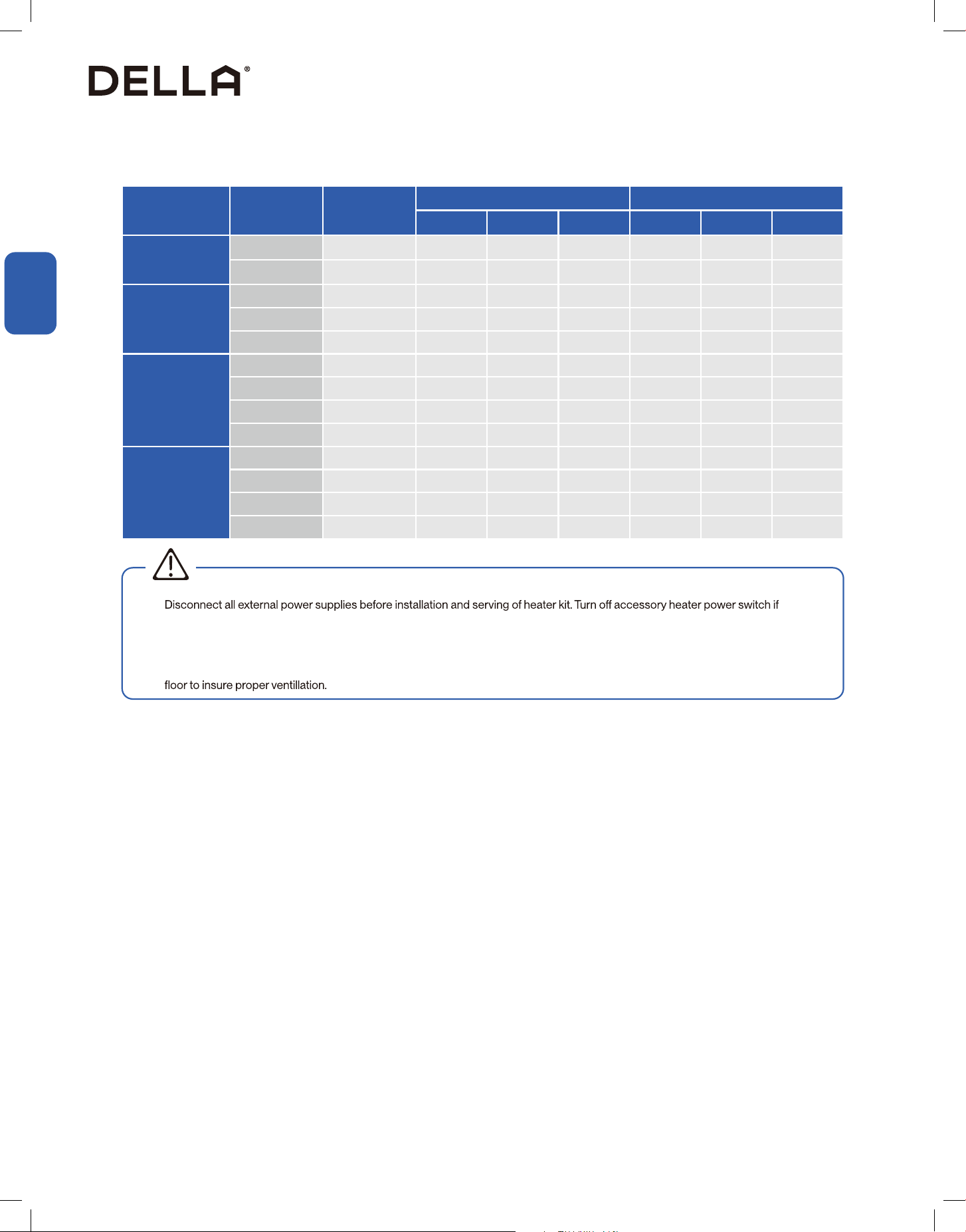
Air Handler Fan Speen Requirement with Auxiliary Heater
Air Handler
Model
Fan Motor
Speed
Available Electric Auxiliary Heater
External Static Pressure-Inches W.C. (Psi)
0 0.1 0.16 0.2 0.3 0.4 0.5 0.6 0.7 0.8
(0) (0.003) (0.005) (0.007) (0.010) (0.014) (0.018) (0.021) (0.025) (0.028)
048-T-24K-IDU
7 1173 1130 1086 1065 1021 956 909 838 791 720
6 1139 1095 1050 1028 983 916 867 795 747 675
5 1105 1059 1013 990 944 875 826 752 703 629
4 1072 1024 977 953 906 835 785 709 659 583
3 1038 989 940 916 868 795 743 666 615 538
2 1004 954 904 879 829 754 702 623 571 492
1 970 919 868 842 791 714 661 580 527 446
048-T-36K-IDU
7 1539 1510 1481 1467 1438 1395 1360 1306 1271 1218
6 1440 1407 1374 1358 1325 1276 1237 1179 1140 1082
5 1340 1304 1267 1248 1211 1156 1114 1052 1010 947
4 1241 1200 1159 1139 1098 1036 992 924 879 812
3 1173 1130 1086 1065 1021 956 909 838 791 720
2 1105 1059 1013 990 944 875 826 752 703 629
1 1038 989 940 926 868 795 743 666 615 538
048-T-48K-IDU
7 1871 1836 1801 1784 1749 1697 1654 1589 1545 1481
6 1779 1746 1713
1696 1663 1613 1572 1510 1469 1408
5 1687 1655 1624 1608 1577 1529 1490 1432 1393 1335
4 1502 1474 1446 1432 1404 1362 1327 1275 1241 1188
3 1410 1377 1345 1329 1296 1248 1210 1154 1116 1060
2 1317 1281 1244 1225 1189 1133 1093 1032 992 931
1 1225 1184 1143 1122 1081 1019 976 911 867 802
048-T-60K-IDU
7 2056 2017 1979 1960 1922 1864 1817 1745 1698 1627
6 1871 1836 1801 1784 1749 1697 1654 1589 1545 1481
5 1587 1655 1624 1608 1577 1529 1490 1432 1393 1335
4 1502 1474 1446 1432 1404 1362 1327 1275 1241 1188
3 1410 1377 1345 1329 1296 1248 1210 1154 1116 1060
2 1317 1281 1244 1225 1189 1133 1093 1032 992 931
1 1225 1184 1143 1122 1081 1019 976 911 867 802
When the air handler is installed with an electric auxiliary heater, the fan speed selection must meet the following static pressure requirement.
Shaded boxes represent pressure outside of the requirement.
30
Installation
Installation
Installation Info (Optional)
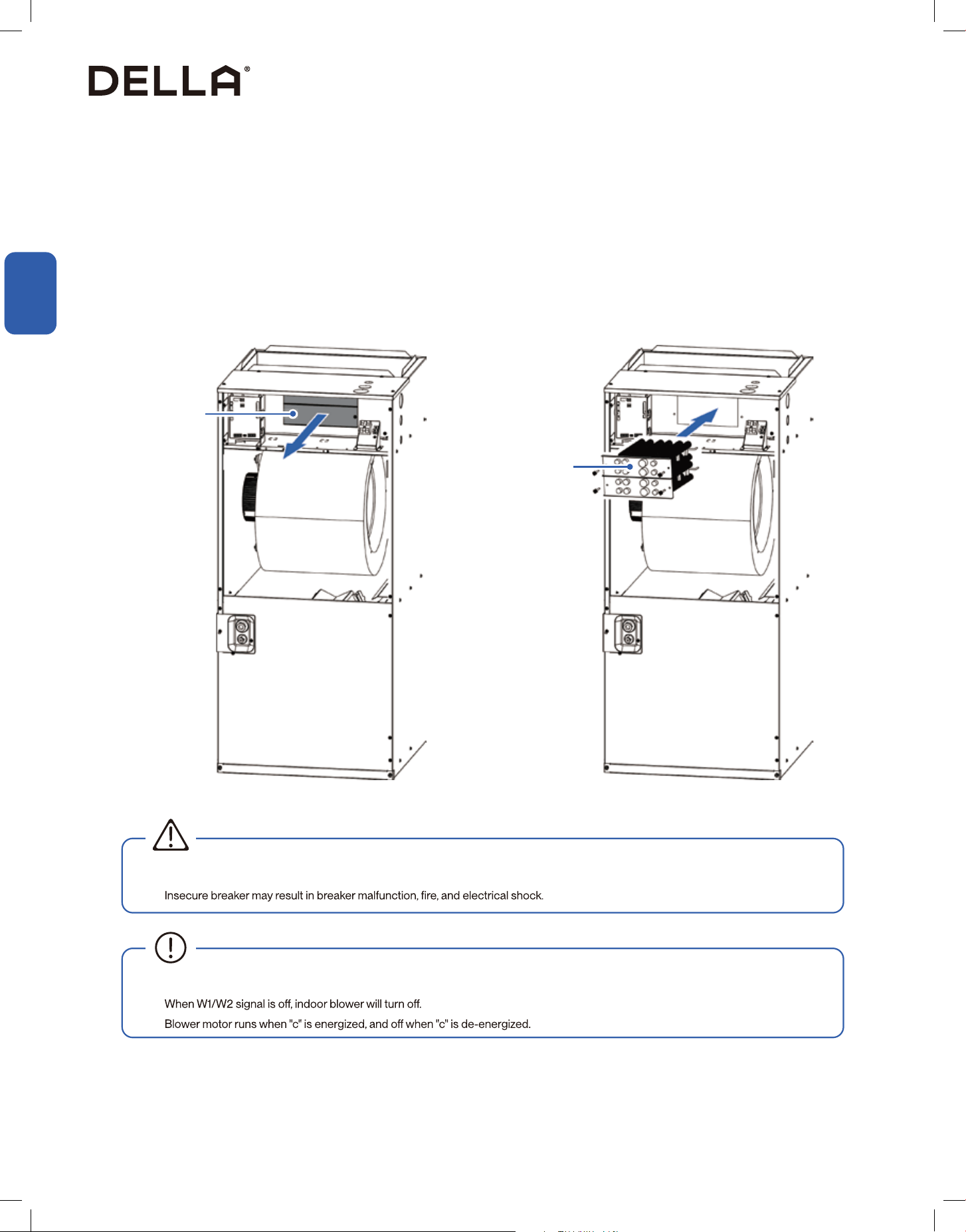
Auxiliary Heater Kit Installation
1. Detach the front upper cover panel from the air handler unit.
2. On the upper shelf, remove the access panels. Keep the screws for later steps.
3. Slide the auxiliary heater kit into the opening. Beware of the orientation, follow the "upper" and "lower" marking on the mounting plate.
4. Align the back of the auxiliary heater to the slots on the air handler, then secure the mounting plate with the screws originally on the access
panels.
5. Connect the electrical wires to the heat kit plug port on the electrical board..
6. Paste the auxiliary heater circuit diagram to the back of the air handler front upper cover panel.
Access Panel
Auxiliary Heater
• After connecting all wires, check if all breakers are secured properly.
•
WARNING
• When indoor control board receives W1/W2 signal, electric heater will be energized and indoor blower will turn on.
•
•
31
v.20251118C
Installation
Installation
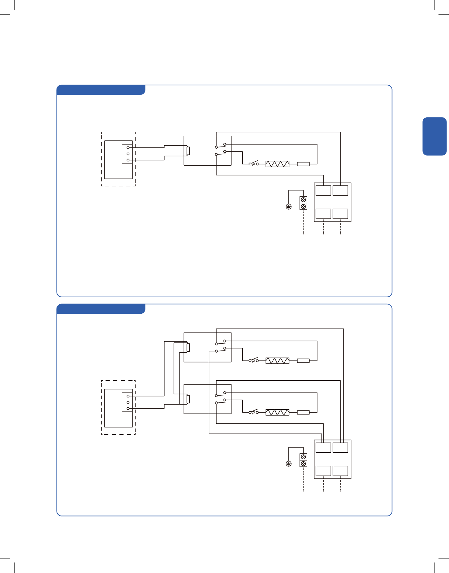
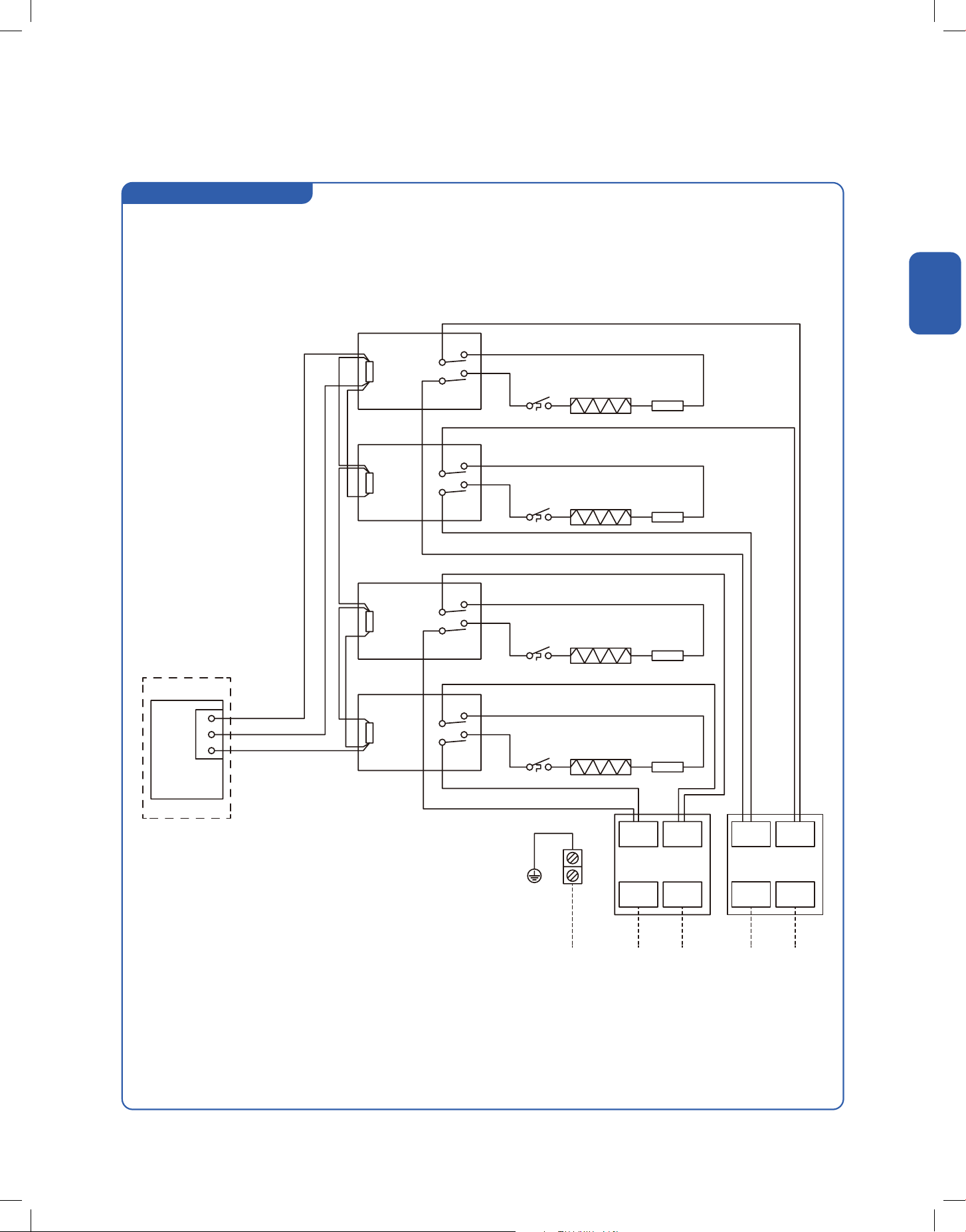
5kW Heater
10kW Heater
Installation Info
Auxiliary Heater Electrical Diagram
PCB
PCB
Heater Kit Plug
Heater Kit Plug
White
White
Red
Red
Red
Black
Black
Black
Black
Black
LS
LS
LS
FL
FL
FL
L1
L1
L2
L2
L1
L1
L2
L2
CB
CB
CB
LS
FL
CB
LS
FL
Circuit Breaker
Limit Switch
Fuse Link
Circuit Breaker
Limit Switch
Fuse Link
5kw Heater Kit / Circuit Breaker 30A
10kw Heater Kit / Circuit Breaker 60A
Elements
Elements
Elements
Black
Red
Red
Red
Brown
Brown
C
C
W1
W1
Relay 1
Relay 1
Relay 1
1
1
1
1
1
6
6
6
8
8
8
0
0
0
2
2
2
2
2
4
4
4
4
4
3
3
CN19
CN19
32
Installation
Installation
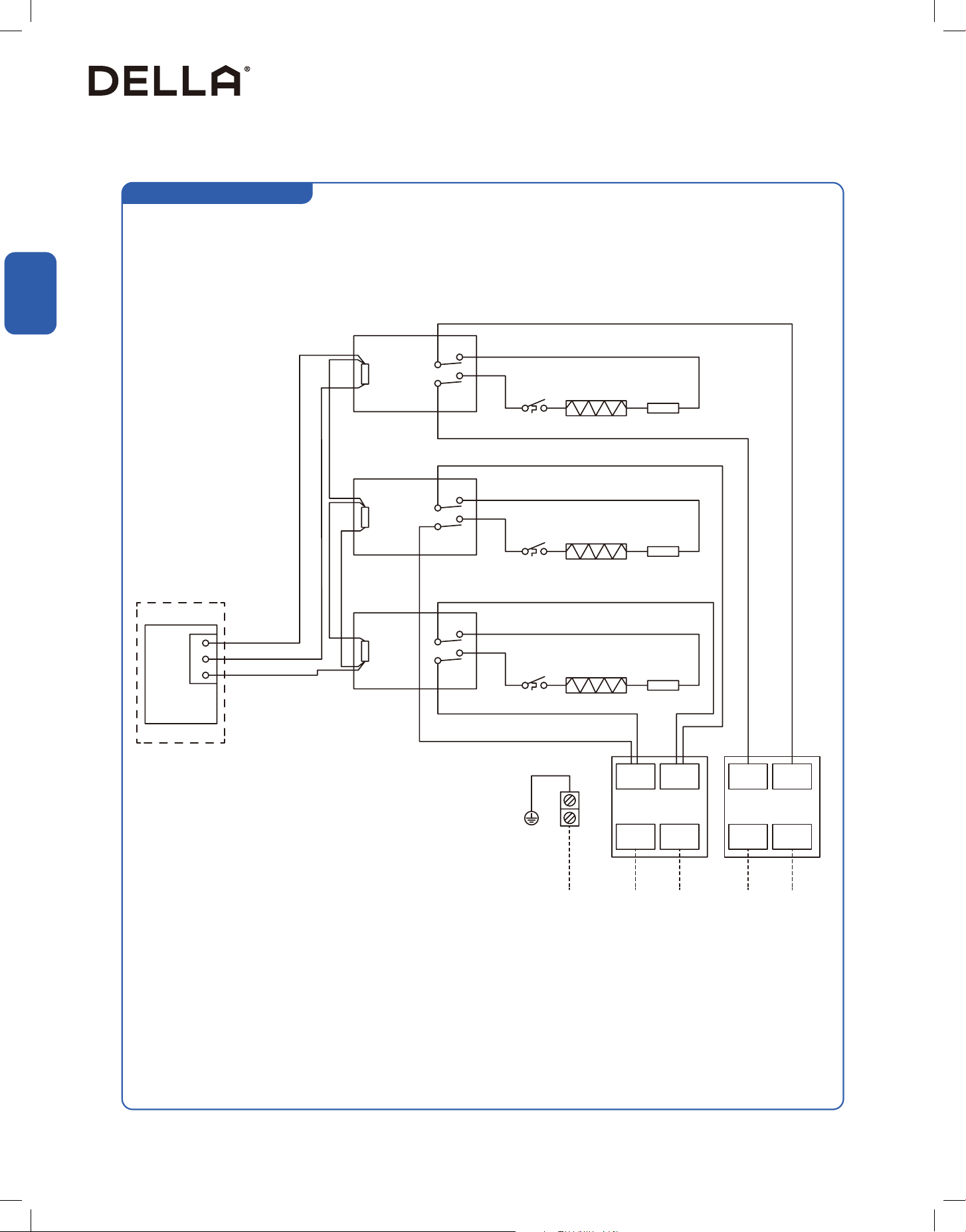
15kW Heater
Installation Info
Auxiliary Heater Electrical Diagram
PCB
White
Red
Red
Red
Red
Black
Black
Black
Black
Black
Black
LS
LS
LS
FL
FL
FL
L1 L1L2 L2
L1 L1L2 L2
CB1 CB2
CB
LS
FL
Circuit Breaker
Limit Switch
Fuse Link
15kw Heater Kit / Circuit Breaker 30A + 60A
Elements
Elements
Elements
Red
Red
Brown
Black / White
C
W2
W1
Relay 1
Relay 1
Relay 2
1
1
1
1 1
6
6
6
8
8
8
0
0
0
2
2
2
2 2
4
4
4
4 4
3 3
CN19
33
v.20251118C
Installation
Installation
20kW Heater
Installation Info
Auxiliary Heater Electrical Diagram
PCB
White
Red
Red
Red
Red
Black
Black
Black
Black
Black
Black
Black
Black
LS
LS
LS
LS
FL
FL
FL
FL
L1 L1L2 L2
L1 L1L2 L2
CB1 CB2
CB
LS
FL
Circuit Breaker
Limit Switch
Fuse Link
20kw Heater Kit / Circuit Breaker 60A + 60A
Elements
Elements
Elements
Elements
Red
Red
Brown
Black / White
W2
C
W1
Relay 1
Relay 1
Relay 2
Relay 2
1
1
1
1
1 1
6
6
6
6
8
8
8
8
0
0
0
0
2
2
2
2
2 2
4
4
4
4
4 4
3 3
CN19
34
System Info
Communication Function DIP Switch
Wind Gear Adjustment DIP Switch
•
controlled and adjusted by the wire controller.
The air handler supports both the conventional 24V communication and RS485 communication protocol to control the unit.
According to the actual installation requirement, the DIP code has to match the communication protocol.
Dip Bit Dip Code Function
SW2-1
Factory default, 24V ON/OFF Control, using 24V thermostat to control unit operation
RS485 communication control, requires wire controllers and communication line from the
manufacturer to meet the use of accessories
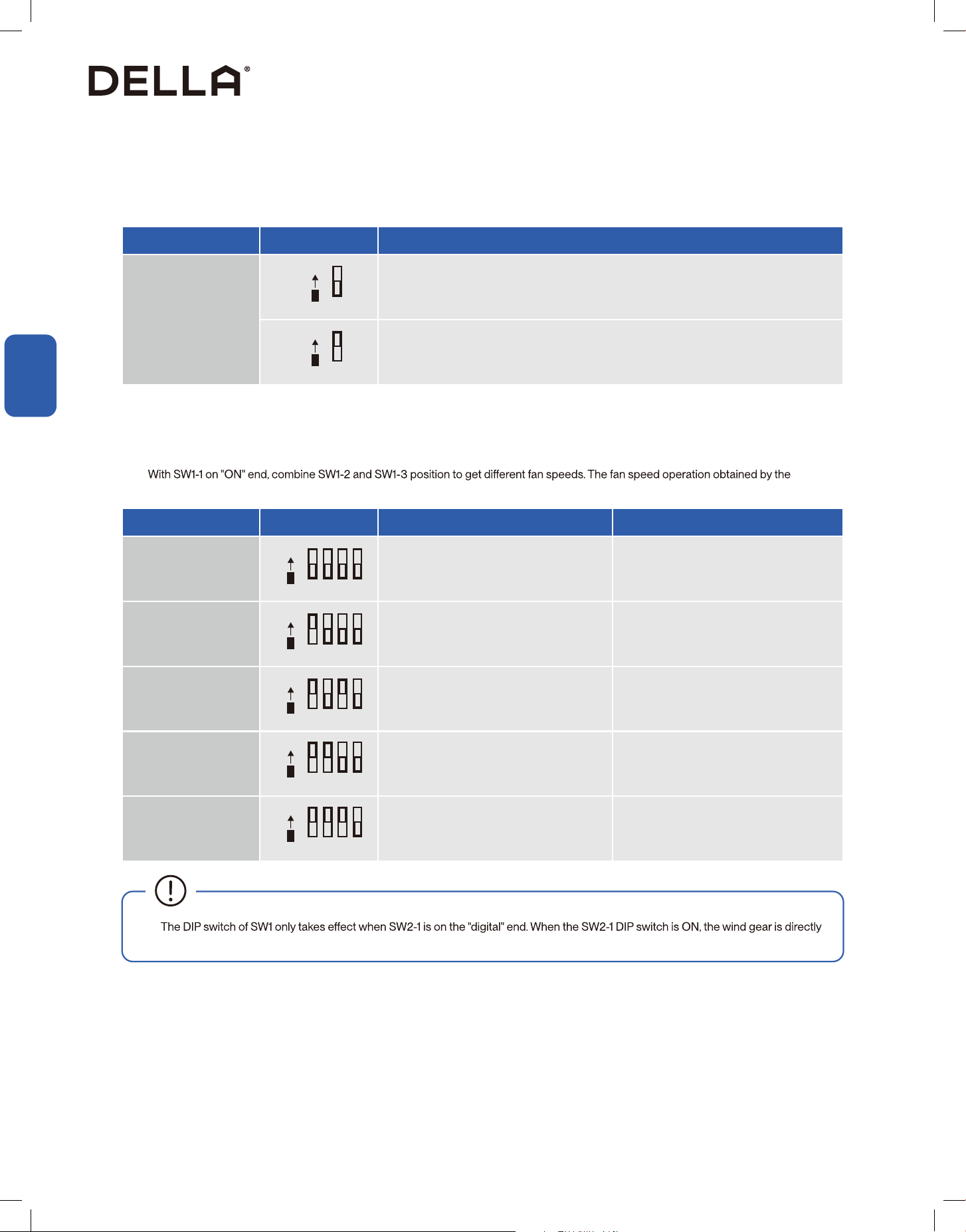
Combination SW1 Setting Low Speed High Speed
1 (Default) Mid - High Grade Super Grade
2 Mid Grade Super Grade
3 Mid - Low Grade Top Grade
4 Low Grade Mid Grade
5 Mute Grade Mid Grade
1
ON
Digital
1
ON
Digital
• When the SW1-1 is located at the digital end (factory default), the fan runs in 5th level for high speed and 2nd level for low speed.
• Switch SW1-1 to the "ON" end if you want to adjust the fan speed.
•
combination is shown as below:
1 2 3 4
ON
Digital
1 2 3 4
ON
Digital
1 2 3 4
ON
Digital
1 2 3 4
ON
Digital
1 2 3 4
ON
Digital
System Info
System Info
35
v.20251118C
System Info
System Info
System Info
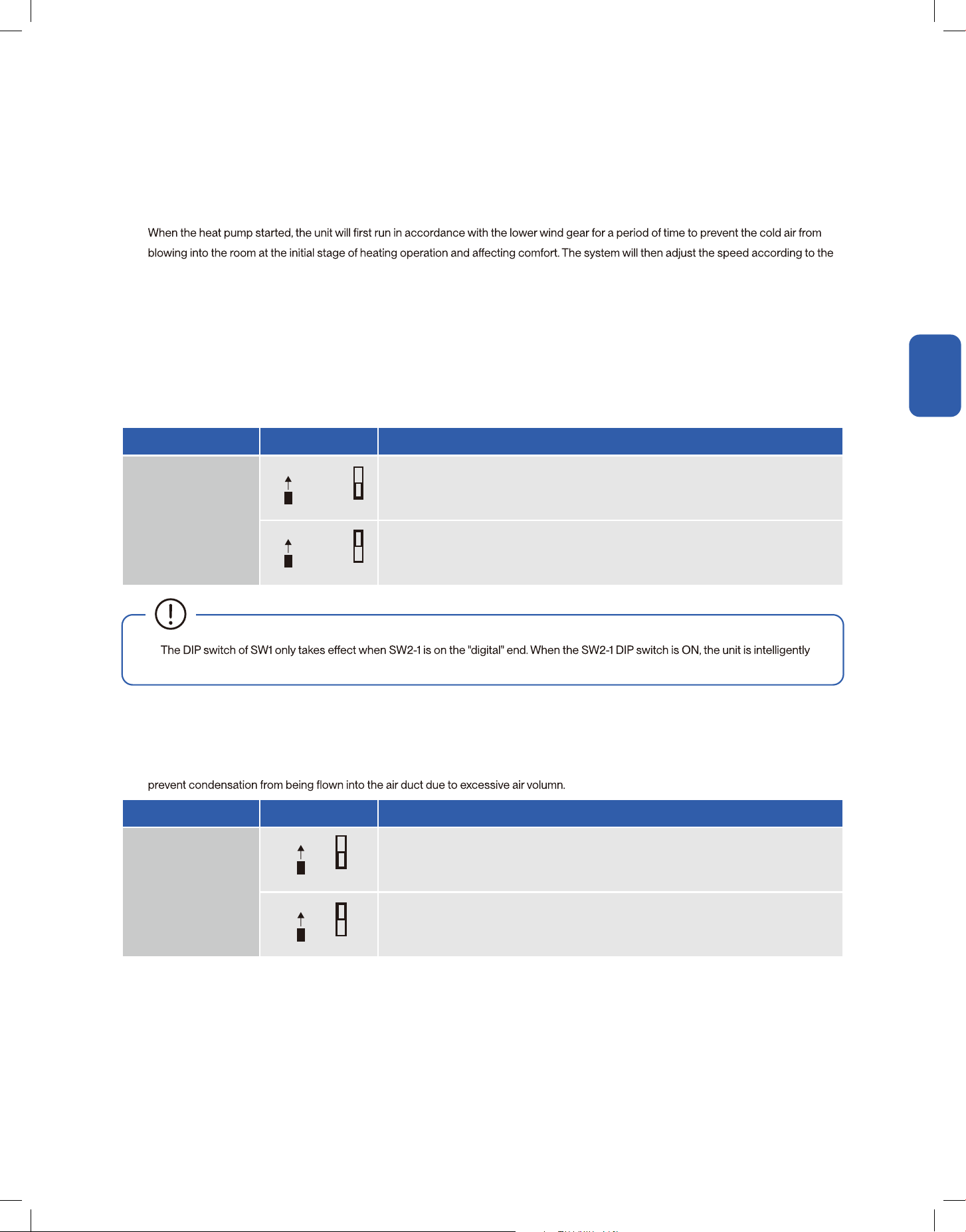
Anti-cold Air DIP Switch
Lower Outlet Air Gear Control Function DIP Switch
•
controlled and the cold air protection function is always enabled.
Dip Bit Dip Code Function
SW1-4
Enable cold air protection function
Disable cold air protection function
Dip Bit Dip Code Function
SW2-2
Use this Dip code position if air is discharged upward or sideway
Use this Dip code position if air is discharged downward
• In 24V ON / OFF control mode, adjusting SW1-4 DIP switch can enable anti-cold air function.
• The default DIP switch position of SW1-4 is on the "digital" end. It would enable cold air protection function.
temperature control wind gear.
The unit determines the defrosting status of the outdoor unit according to the signal of terminal D. During the outdoor unit defrosting
operation, the indoor unit stop running to prevent cold air from blowing into the room. When the unit complete the defrosting process, it will
adjust the rotational speed according to the temperature control air gear.
In electric heating operation, the unit will control the fan operation according to the temperature control wind gear, and do not perform anti-
cold wind action.
• Anti-Cold air funtcion can be turned OFF by switching the SW1-4 DIP switch to the "ON" end, and the unit controls the fan operation
according to the control wind gear of the thermostat, and does not implement the anti-cold wind control system.
• The default DIP switch position of SW2-2 is on the "digital" end.
• If the unit is installed at the bottom air outlet, switch the SW2-2 DIP switch to "ON" end. The unit will control the upper limit of the air gear to
4
ON
Digital
4
ON
Digital
2
ON
Digital
2
ON
Digital
36
System Info
System Info
System Info
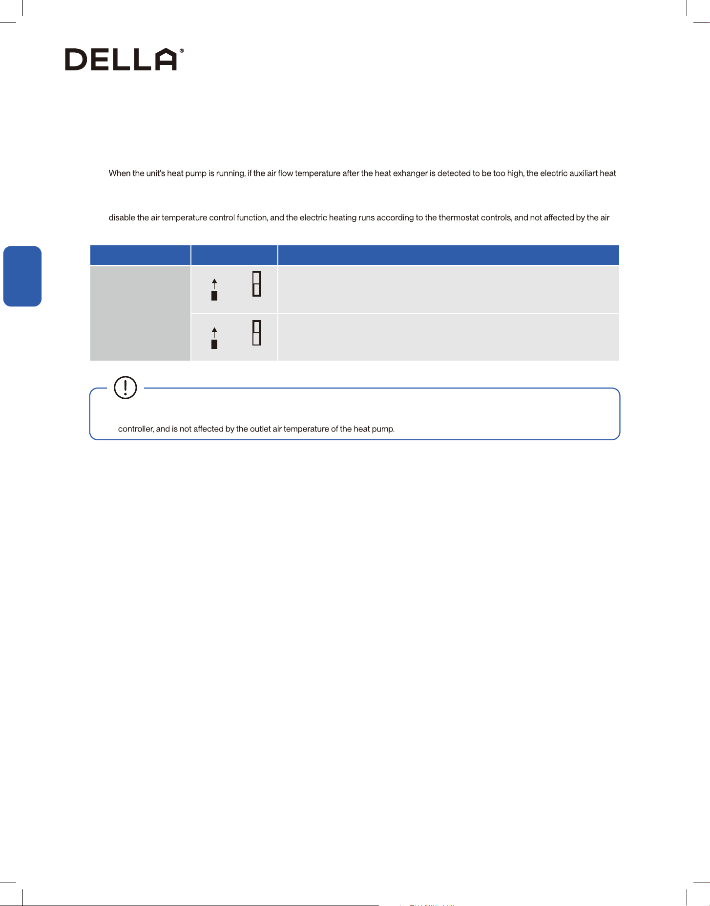
Cold Air Prevention
SW2-4 DIP Switch
In 23V ON / OFF control mode, SW2-3 DIP switch can be adjust for exhaust air temperature control function.
• The default DIP switch position of SW2-3 is on the "digital" end, The unit's exhaust air temperature control function is enabled.
will be controlled not to start to prevent electric heaing temperature from being too high and triggering overheating protection.
• If the air temperature from the equipement need to be further increased, adjust the SW2-3 DIP switch position to the "ON" end. It will
temperature detected on the heat pump.
• SW2-4 DIP switch should be remain as factory default (on the "digital" end). Do not adjust this DIP switch.
Dip Bit Dip Code Function
SW2-3
Enable exhaust air temperature control function
Disable exhaust air temperature control function
3
ON
Digital
3
ON
Digital
• In emergency heating mode, when the heat pump is not running, the electric heating runs according to the control of the temperature
37
v.20251118C
System Info
System Info
System Info
Indicating Light (For 24V Communication Protocol)
• The LED light only works with 24V communication; RS485 communication is not displayed, the wired controller displays the fault code.
LED Color LED Status Discription
Green OFF Standby Mode
Green Stays ON In Operation
Green 1 Flash Anti-Cold Air Function is Active
Green 2 Flashes Electric Auxilary Heating is Active
Green 3 Flashes Commodity Inspection Status
Green 4 Flashes Self-Check Status
Red OFF Trouble-free
Red Stays ON Refrigerant Leak Protection Active
Red 1 Flash Refrigerant Sensor Communication Abnormal
Red 2 Flashes Internal Fan Fault
Red 3 Flashes Internal Coil Temperature Sensing Packet Fault
Red 4 Flashes Supply Air Temperature Sensing Packet Fault
Red 5 Flashes EEPROM Fault
Red 6 Flashes Indoor / Outdoor 485 Communication Failure
Red 7 Flashes Controller 485
38

Troubleshooting
Having Problems?
Having Problems?
•
•
• The unit continually trips fuses or circuit breakers.
• A foreign object or water enters the air conditioner.
• The indoor unit leaks
• Other abnormal situations
CAUTION
When Problem Possible Cause / Explanation / Solution
Abnormal noises from the outdoor unit
abnormally loud.
Noises from both indoor and outdoor unit
A hissing sound could be heard when the AC enter defrost mode and stop refrigerant gas from
Unit does not turn ON
The unit has a 3 minutes protection that prevent it from overloading. It cannot be restarted
Cooling and Heating mode: If the operation light and PRE-DEF (pre-heating / defrost) indicators
are lit, the outdoor temperature is too cold, the unit will attempt to defrost before operating
normaly.
The unit changes from cool mode to fan
mode
The unit changes its setting to prevent frost from forming on the unit. Once the temperature
increases, the unit will start operating again.
Both the indoor and outdoor unit emit white
mist
When the unit restart in heat mode after defrosting, white mist may be emitted due to moisture
generated from the defrosting process.
Dust is emitted from either the indoor or
outdoor unit
The unit may accumulate dust during extended periods of non use, which will be emitted when
the unit is turned on. This can be mitigated by covering the unit during long periods of inactivity.
The unit emits a bad odor
The unit may abosrb odors from the environment (such as furniture, cooking, cigarettes, etc.)
which will be emitted during operations.
39
v.20251118C
Troubleshooting
Having Problems?
Having Problems?
When Problem Possible Cause / Explanation / Solution
The outdoor unit fan does not operate In normal operation, the fan speed is controlled to optimize product operation.
The unit is not working
Power failure. Restore power supply and restart the unit again.
The power switch is OFF, Turn the power back ON and restart the unit.
Breaker has been triggered. Reset the breaker.
The unit's 3 minutes protection has been triggered. Wait 3 minutes and restart the unit.
Poor cooling performance
Temperature setting may be higher than the ambient room temperature. Lower the temperature
setting.
Doors or windows are open. Close the door or windows while operating the AC
Excessive heat is generated by sunlight. Close windows and curtains to block sunlight
generated heat.
Low refrigerant due to leak or long-term use. Contact HVAC technician and check on
refrigerant level. Re-charge the system if necessary.
Poor heating performance
The outdoor temperature is lower than operational temperature
Cold air is entering through doors and windows. Close the door or windows while operating the
AC
Low refrigerant due to leak or long-term use. Contact HVAC technician and check on
refrigerant level. Re-charge the system if necessary.
40

© Della All rights reserved.
notice for product improvement. Any updates to the manual will be
uploaded to the della website.
www.dellahome.com
support@dellahome.com
800 863 4143
6:00 a.m. 4:00 p.m. PST Monday Friday
Central AC (T) Series
Compressor
Instruction Manual
Installation and Operation Guide

Table of Content
Warning and Safety 04
Before Installation
Installation Location
Refrigerant Lineset Connection
Pressure Test
Evacuation
Refrigerant Valve
Low Voltage Connection
High Voltage Connection
Circuit Diagram
Test Run
12
13
22
23
24
25
28
30
31
Installation
32
35
36
Display Code
Major Componant Function
Troubleshooting
System Info
Having Problems?
43
v.20251118C
Before Installation
Before Installation
Warning and Safety
• Read this guide before installation. Failure to follow the safety instructions may result in property damage, serious injury, or death.
• Please Keep this manual.
Danger:
Indicates an IMMINENTLY hazardous situation that, if not avoided, will result in death, serious injury, or serious property damage.
Warning:
Indicates an POTENTIALLY hazardous situation that, if not avoided, will result in death, serious injury, or serious property damage.
Caution:
Indicates an POTENTIALLY hazardous situation that, if not avoided, will result in minor to moderate injury. It may also be used to
indicate unsafe practice.
Attention:
Pay additional attention to the instruction.
DO NOT:
Indicates prohibited actions and / or practice.
DANGER
WARNING
CAUTION
About Refrigerant
• The air conditioner is pre-charged with R454B refrigerant. Handle the air conditioner with care and check if there is any
refrigerant may cause frostbite, cardiac arrhythmia, and / or irritation, as well as cause environmental damage.
• In the case of refrigerant leakage, shut down the appliance and disconnect from the power supply. An inspection must
•
and licensed technician.
• When installing or using the appliance with R454B refrigerant, beware of the following symbols.
• Length and area limitation and recommendation should be followed. Store and install the appliance in rooms which size
• The length of pipe work should be kept at minimum.
•
• All national, state, and local regulations on handling and installing R454B refrigerant should be followed.
• Do not install or store the compressor in area or room with continuously operating ignition sources.
• Prior to any work and servicing on systems containing ammable refrigerant, safety checks are necessary to ensure that
the risk of ignition is minimized.
DANGER
Additional Information About R454B Refrigerant
WARNING
•
• This symbol means that read the operation insturction carefully.
• This symbol means that personnel handling the equipment should reference to the installation manual.
• This symbol means information is available in the installation or operation instruction manual.
44

Before Installation
Before Installation
Warning and Safety
•
• The work area shall be checked with refrigerant detector prior to and during work to ensure the technician is aware of
•
equipment shall be available to hand.
• Personnel carrying out work in relation to the refrigeration system which involves exposing any pipe work shall not use
displayed.
• Ensure the work area is in the open or that it is adequately ventilated before breaking into the system or conducting any
work that will produce heat. A degree of ventilation shall be kept during the period which work or service is carried out.
• During installation or repairs to sealed components, all electrical supplies shall be disconnect from the equipment. A
permanent operating leak detection shall locate at the work area to detect potential hazardous leaks.
•
Additional Information About R454B Refrigerant
WARNING
• The refrigerant charge amount is in accordance with the room size within which the refrigerant containing parts are
installed.
• The ventilation machinery and outlet are operating adequately and are not obstructed.
• If an indirect refrigerating curcuit is being used, the secondary circuit shall be check for the presence of refrigerant.
• Refrigerant pipe or components are installed in a position where they are unlilely to be exposed to any substance
which may corrode refrigerant containing components, unless the components are constructed of materials which
are inherently resistant to being corroded or are suitable protected against being corroded.
• Refrigerant charge shall be recovered into recovery cylinders, All refrigerant recovery procedure shall follow local
and national regulations. Oxygen free nitrogen shall be purged through the system after refrigerant recover.
• When decommissioning the appliance, it is recommended that all refrigerants are recovered. The system should be
isolated electrically, and recovered refrigerant should not be charged into another re
frigeration system unless it has
been analized to be safe to do so.
•
dated and signed.
• Under no circumstances shall potential sources of ignition be used in the searching for or detection of refrigerant
•
source of ignition and is suitable for the refrigerant used.
• Leak detection equipment shall be calibrated to the refrigerant employed and the appropriate percentage of gas
•
be avoided as chlorine may react with the refrigerant and corrode the pipe work.
•
• If a leakage of refrigerant found which requires brazing, all of the refrigerant shall be recovered from the system, or
• Oxygen free nitogen shall be purged through the system both before and during the brazing process.
•
• Decommissioning and recovery of refrigerants:
45
v.20251118C
Before Installation
Before Installation
Warning and Safety
Additional Information About R454B Refrigerant
WARNING
• -
erant is suitabe for system needing additional refrigerant charge and which will limit the area of rooms being served by
the system. Similarly, the total amount of refrigerant in the system shall be less than or equal to the allowable maximum
refrigerant charge. The allowable maximum refrigerant charge depends on the area of the rooms being served by the
system.
• For R454B refrigerant, the maximum charge in a room shall be in accordance with the following:
• M = Mass
• M
max = Maximum charge mass
• M
c = Mass charged
• A = Floor area
•
1. It is a permanent opening.
2.
3. It is intened for people to walk through.
1. The opening shall not be less than Anv
min in [Table 1-1].
2. The area of any opening above
compliance with Anvmin.
3. At least 50% of the opening area of Anv
min shall be below
4. The bottom of the opening is not more than
5. The opening is a permanent opening that cannot be closed.
6.
inches above the surface of the
• Low level opening:
•
partitions and doors of the space in which the appliance is installed.
• Space connected by only drop ceilings, ductwork, or similar connections shall not be considered as a single
• Rooms on the same oor and connected by an open passageway between the space can be considered a
single room when determining compliance to A
min, if the passageway complies with all the followings:
•
room when determining compliance to Amin, provided all of the following conditions are met as [Fig 1-1].
•
min to install an appliance with refrigerange Mc (kg) shall be in accordance with:
• Room area calculation requirements:
• M
max = SF x LFL x h
• The space considered shall be any space which contains refrigerant-containing parts or into which refrigerant
refrigerant.
•
• Amin = Mc / (SF x LFL x h
46

Before Installation
Before Installation
Warning and Safety
Additional Information About R454B Refrigerant
WARNING
1. The opening shall not be less than 50% of Anvmin in [Table 1-2].
2. The opening is a permanent opening that cannot be closed.
3.
4. The height of the opening is not less than inches.
1. The room into which refrigerant can leak, plus the connected adjacent room(s) shall have a total area not
less than A
min. Amin is shows in [Table 1-4].
2. The room area in which the unit is installed shall not be less than 20% A
min. Amin is shows in [Table 1-4].
• High level opening:
• Room size requirement:
• The requirement for the second opening can be met by drop ceiling ventilation ducts, or similar arrangements
• The minimum opening for natural ventilation (Anvmin
actual refrigerant charge in the system (Mc), and the allowable maximum refrigerant charge in the system
(M
max). Anvmin can be determined according to [Table 1-2].
Fig 1-1 Opening Requirement for Connected Rooms
≥ ”
≥ 59”
≥
”
≥ 50% of Anv
min
≥ 50% of Anvmin
≥ ”≥ ”
≥
47
v.20251118C

Before Installation
Before Installation
Warning and Safety
Additional Information About R454B Refrigerant
WARNING
A (sq. ft) Mc (lb oz) Mmax (lb oz) Anvmin (sq ft)
40 9lb 9oz 2lb 10oz 0.9
50 9lb 9oz 3lb 5oz 0.8
60 9lb 9oz 4lb 0oz 0.7
70 9lb 9oz 4lb 10oz 0.6
80 9lb 9oz 5lb 5oz 0.6
90 9lb 9oz 6lb 0oz 0.5
100 9lb 9oz 6lb 10oz 0.4
110 9lb 9oz 7lb 5oz 0.3
120 9lb 9oz 8lb 0oz 0.2
130 9lb 9oz 8lb 10oz 0.2
140 9lb 9oz 9lb 5oz 0.1
150 9lb 9oz 10lb 0oz 0.0
160 9lb 9oz 10lb 10oz 0.0
A / TA (sq. ft) Mmax (lb oz)
40 2lb 10oz
50 3lb 5oz
60 4lb 0oz
70 4lb 10oz
80 5lb 5oz
90 6lb 0oz
100 6lb 10oz
110 7lb 5oz
120 8lb 0oz
130 8lb 10oz
140 9lb 5oz
150 10lb 0oz
A / TA (sq. ft) Mmax (lb oz)
160 10lb 10oz
170 11lb 5oz
180 12lb 0oz
190 12lb 10oz
200 13lb 5oz
210 14lb 0oz
220 14lb 10oz
230 15lb 5oz
240 16lb 0oz
250 16lb 10oz
260 17lb 5oz
Table 1-2 The Minimum Opening Area for Connected Rooms
Table 1-3 The Allowable Maximum Refrigerant Charge
•
distributed to all the rooms by the appliance integral indoor fan will mix and dilute the leaking refrigerant before entering
any room.
•
• If the fan incorporated to an appliance is continuously operated or operation is initiated by a refrigerant detection
max) and the required
min / TAmin) is shown in [Table 1-3] and [Table 1-4]
48
Before Installation
Before Installation
Warning and Safety
Additional Information About R454B Refrigerant
WARNING
Mc (lb oz) Amin / TAmin (sq. ft)
4lb 6oz 66.1
4lb 13oz 72.7
5lb 4oz 79.3
5lb 11oz 86.0
6lb 2oz 92.6
6lb 9oz 99.2
7lb 0oz 105.8
7lb 7oz 112.4
7lb 15oz 119.0
8lb 6oz 125.6
8lb 13oz 132.2
9lb 4oz 138.8
9lb 11oz 145.5
10lb 2oz 152.1
10lb 9oz 158.7
Mc (lb oz) Qmin (CFM)
4lb 6oz 119
4lb 13oz 131
5lb 4oz 143
5lb 11oz 155
6lb 2oz 167
6lb 9oz 179
7lb 0oz 191
7lb 7oz 203
7lb 15oz 215
8lb 6oz 227
8lb 13oz 239
9lb 4oz 251
9lb 11oz 263
10lb 2oz 275
10lb 9oz 287
Mc (lb oz) Amin / TAmin (sq. ft)
11lb 0oz 165.3
11lb 7oz 171.9
11lb 14oz 178.5
12lb 5oz 185.1
12lb 12oz 191.7
13lb 3oz 198.4
13lb 10oz 205.0
14lb 1oz 211.6
14lb 8oz 218.2
14lb 15oz 224.8
15lb 6oz 231.4
15lb 14oz 238.0
16lb 5oz 244.6
16lb 12oz 251.2
17lb 3oz 257.9
Mc (lb oz) Qmin (CFM)
11lb 0oz 298
11lb 7oz 310
11lb 14oz 322
12lb 5oz 334
12lb 12oz 346
13lb 3oz 358
13lb 10oz 370
14lb 1oz 382
14lb 8oz 394
14lb 15oz 405
15lb 6oz 418
15lb 14oz 430
16lb 5oz 442
16lb 12oz 454
17lb 3oz 466
Table 1-4 The Required Minimum Floor Area
Table 1-4 The Required Minimum Floor Area
49
v.20251118C

Before Installation
Before Installation
Warning and Safety
Additional Information About R454B Refrigerant
WARNING
•
only if the following conditions are met:
• The maximum refrigerant limit described above applies to unventilated areas. If additional measures such as mechanical
ventilation or natural ventilation are implemented, the maximum refrigerant charge can be increased or the minimum
•
which is related to the actual refrigerant charge of the system (Mc).
About Installation
• Do not alter, change, or modify the appliance.
• Prevent children from accessing the work area during installation to prevent unforeseeable accident.
•
• Carry out a test run after the installation.
• The packaging materials are recyclable and should be disposed of in a separate waste bins.
• The appliance should not be installed in a location where the air outlet of the indoor or outdoor unit is obstructed.
Obstruction of these opening may cause damage or malfunctions to the appliance.
WARNING
CAUTION
About Power and Electricity
• Ensure that the power voltage corresponds to that stamped on the rating plate.
• A fuse or overload protection device with a suitable capacity be installed.
•
over-voltage category III conditions. All electrical wiring must follow federal, state, or local regulations.
• When working on the electric terminals, ensure the appliance is disconnected from the power supply.
• Make sure the appliance is properly grounded to prevent electric shock.
• Do not bend, tug, or compress the power cord during installation to prevent damaging the power cord. Damaged
WARNING
WARNING
50

Before Installation
Before Installation
Warning and Safety
About Operation
•
•
• Do not climb onto or place any objects on the appliance.
• Do not insert any objects into the appliance to prevent damage or injury.
• Do not obstruct the air inlet or outlet.
• Only use the appliance as instructed in this booklet. These instructions are not intended to cover every possible
condition and situation. As with any electrical household appliance, common sense and caution are therefore always
recommended for usage and maintenance.
WARNING
CAUTION
Encountering Troubles
• In the case of the appliance emitting smoke, burning smell, leaking water, or making unusual noise, shut down the
WARNING
51
v.20251118C
Installation
Installation
> 60" unrestricted space
> 24" unrestricted space
≥ 24"
≥ 24"
> 24"
unrestricted space
> 12" to cloest obstacle / vegetation
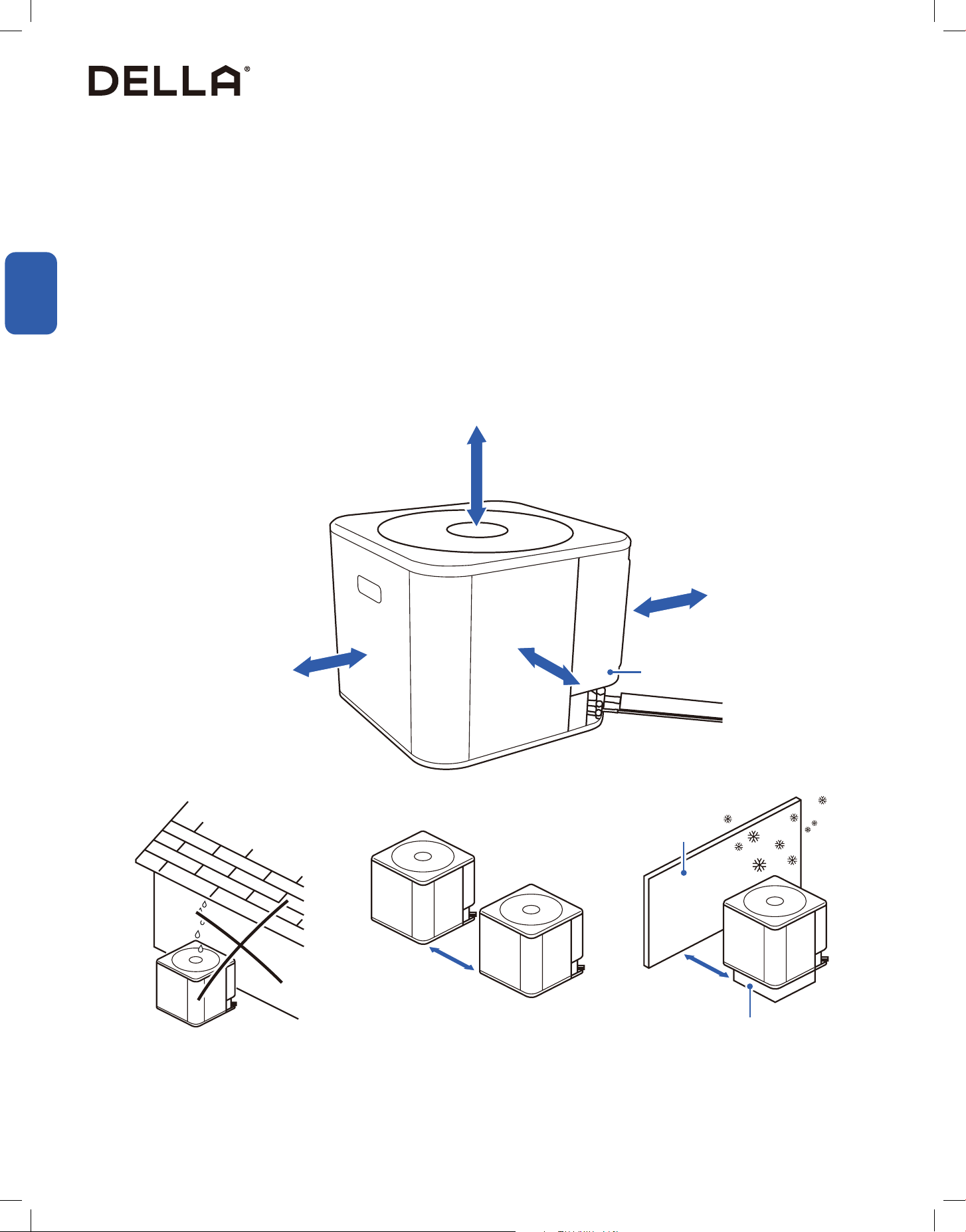
• Avoid installing the compressor in corrosive environment. Corrosive elements include, but not limited to sodium chloride, sodium
hydroxide, sodium sulfate, and other compounds commonly found in ocean water, sulfur, chlorine, uorine, fertilizers, and various chemical
contaminants from industy or manufacturing plants.
• Avoid locations where lawn sprinklers or waste water would directly spray on the unit for prolonged period.
• Avoid installing the compressor near bedrooms to minimize noise disturbance.
• When installing in coastal areas, place the unit on the side of the building away from the water front.
• When installing in cold climate, elevated pad might needed to help drainage of melted ice during defrost cycle. A snow drift barrier should
also be installed around the unit to prevent build up of snow.
• When installing the compressor on a roof, make sure the roof can support the weight of the compressor. Dampening would needed to
minimize sound and vibration.
• Follow the clearance requirement as below:
Installation Info
Installation Location
Access Panel
3" - 12" Elevated Pad
Snow Barrier
Avoid water or snow from falling into
the unit for prolonged period
Place units 24" apart from each other Place snow barrier and elevated pad if
using the unit in snowy climate
52
Installation
Installation
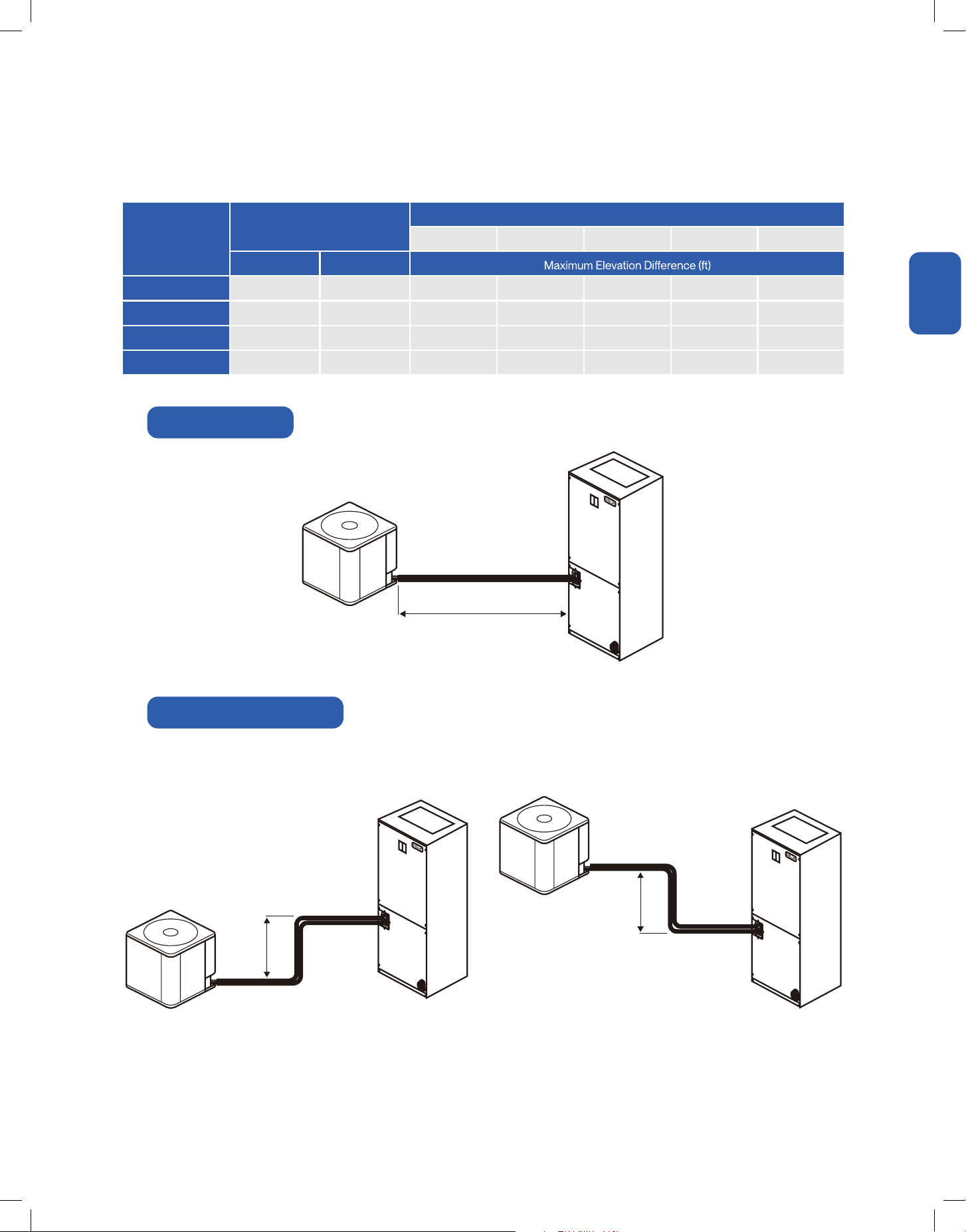
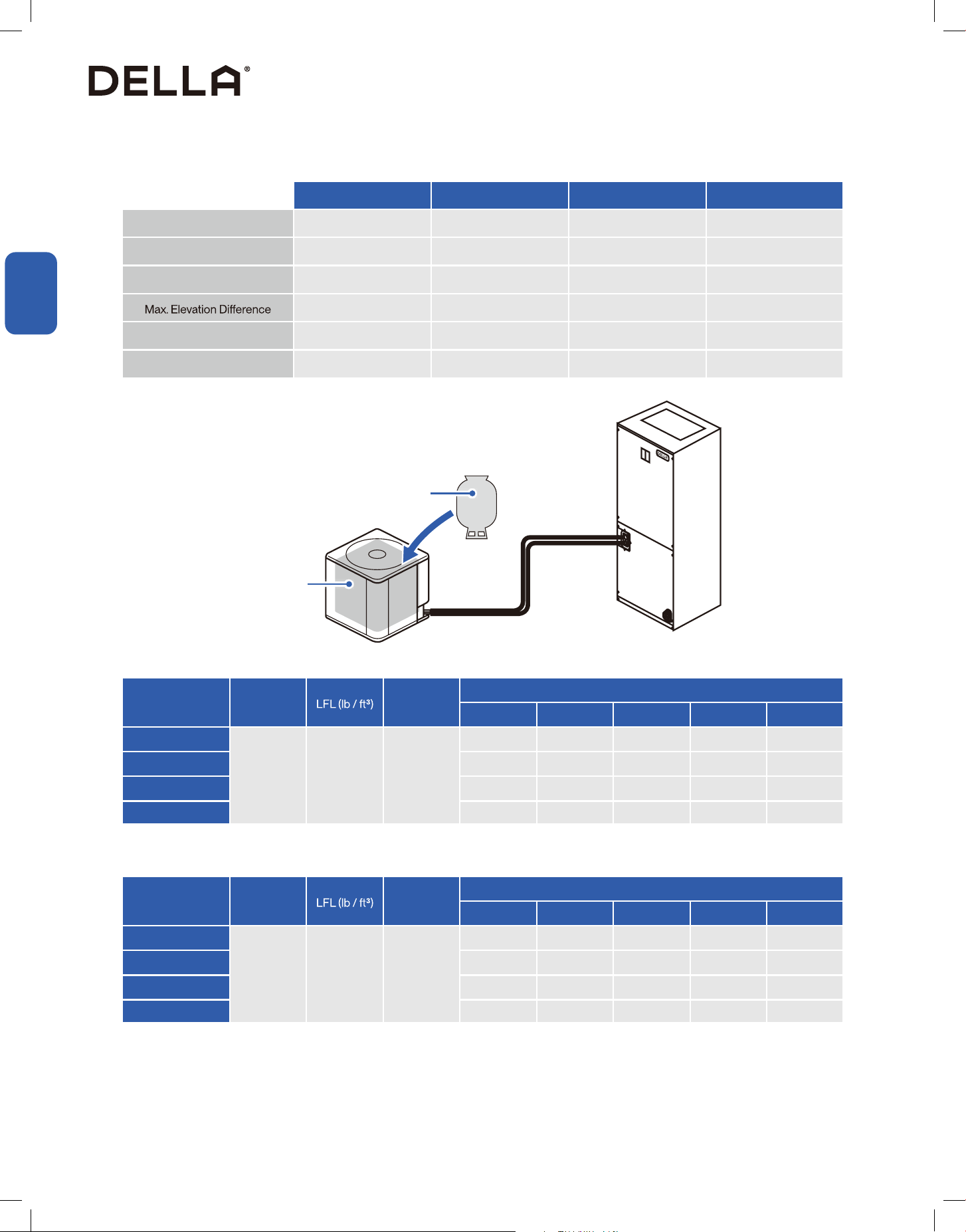
• Only use line sizes indicated in below table and follow line length limiitation.
Installation Info
Refrigerant Lineset
Line Length
Elevation Dierence
Elevation Dierence
Model
OD Diameter (inch)
Total Equivalent Length (ft)
25 50 75 100 164
Liquid Line Suction Line
048-T-24K-ODU 3/8 3/4 25 50 45 40 /
048-T-36K-ODU 3/8 3/4 25 50 50 40 /
048-T-48K-ODU 3/8 7/8 25 50 50 40 35
048-T-60K-ODU 3/8 7/8 25 50 50 40 35
Maximum Line Lengh
Maximum Elevation Dierence
53
v.20251118C
Installation
Installation
Installation Info
Pipe Length and Additional Refrigerant Info
Total Refrigerant Capacity
Minimum Floor Area
Model Refrigerant h0 (ft)
Pipe Length (ft)
25 49 66 98 164
048-T-24K-ODU
R454B 0.0185 7.2
4.74 lb 5.57 lb 6.12 lb 7.22 lb /
048-T-36K-ODU 6.28 lb 7.11 lb 7.66 lb 8.76 lb /
048-T-48K-ODU 8.82 lb 9.65 lb 10.2 lb 11.3 lb 13.5 lb
048-T-60K-ODU 8.82 lb 9.65 lb 10.2 lb 11.3 lb 13.5 lb
Model Refrigerant h0 (ft)
Pipe Length (ft)
25 49 66 98 164
048-T-24K-ODU
R454B 0.0185 7.2
71 sq. ft 26 sq. ft 28 sq. ft 33 sq. ft /
048-T-36K-ODU 95 sq. ft 32 sq. ft 35 sq. ft 40 sq. ft /
048-T-48K-ODU 40 sq. ft 44 sq. ft 47 sq. ft 52 sq. ft 62 sq. ft
048-T-60K-ODU 40 sq. ft 44 sq. ft 47 sq. ft 52 sq. ft 62 sq. ft
048-T-24K-ODU 048-T-36K-ODU 048-T-48K-ODU 048-T-60K-ODU
Stand Charge Pipe Length 25 ft 25 ft 25 ft 25 ft
Standard Charge Capacity 4.74 lb 6.28 lb 8.82 lb 8.82 lb
Max. Pipe Length 100 ft 100 ft 165 ft 165 ft
50 ft 50 ft 50 ft 50 ft
Additional Refrigerant Charge 0.0335 lb / ft 0.0335 lb / ft 0.0335 lb / ft 0.0335 lb / ft
Type of Refrigerant R454B R454B R454B R454B
Additional Refrigerant
Standard
Refrigerant Charge
Standard Refrigerant Charge+ Addition Refrigerant
= Total Refrigerant Amount
54
Installation
Installation
Installation Info
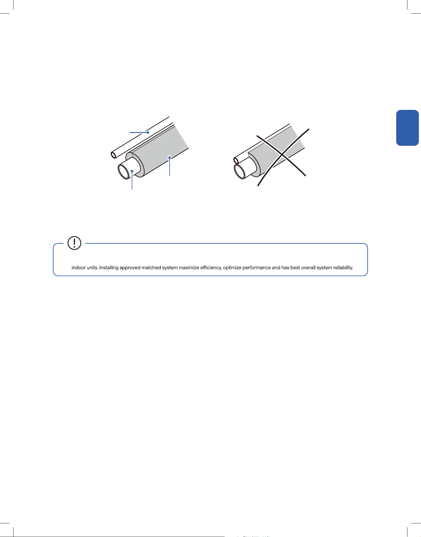
Refrigerant Line Insulation
Reusing Existing Refrigerant Line
• The suction line must always be insulated.
• Liquid line insulation is optional.
• The liquid line should not be come into direct metal to metal contact with the suction line.
• For retrot applications where the existing refrigerant lines will be used, ensure that the refrigerant line are the correct size.
• It is not recommended to use suction line larger than standard size, in which will result poor oil return for inverter compressor.
• Clean the existing refrigerant line by purging nitrogen into the lineset.
Liquid Line
Suction Line
Insulation
• It is recommended to install matched outdoor and indoor system. All of the manufacturer's split systems are AHRI rated with TXV
55
v.20251118C
Installation
Installation
Installation Info
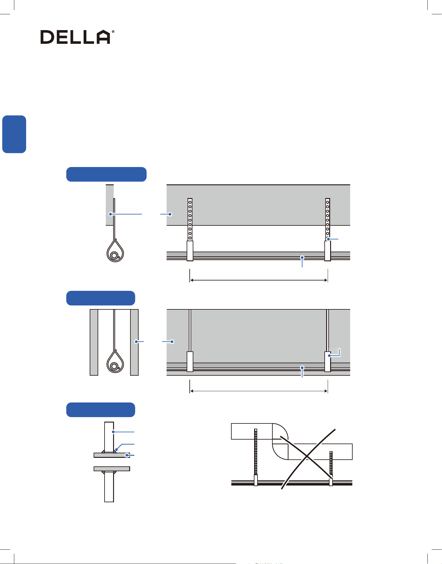
Refrigerant Line Routing
When isolating linesets from joists, rafters, walls, or other structural elements, comply with all national, state, and local codes.
Refrigerant line should be arranged to minimize noise and vibration within the building structure.
• Use isolation type hangers when the refrigerant line have to be fastened to oor joists or other framing.
• Isolation hangers should be used with refrigerant lines traverse stud space or enclosed ceilings.
• Isolate and insulate the refrigerant line where it pass through a wall or sill.
• Isolate the refrigerant line from all ductwork.
• Minimize the number of 90° turns on the refrigerant line.
• Secure suction line using isolators every 8ft. Secure liquid line directly to insulated suction line using tape, wire, or other appropriate method
every 8ft.
• Do not hand lineset onto ductwork.
Lineset
Isolator
Rafter
≤ 8ft
≤ 8ft
Lineset
Wall
Wall
Suction Line Insulation
Sealant
Isolator
Isolation from Joist / Rafter
Isolation in Wall Space
Isolation in Wall Space
56

Installation
Installation
Installation Info
Cut new or existing refrigerant line to your desired lenghth.
Cutting the Refrigerant Pipe
1. Cut the copper pipe with a pipe cutter.
2. Remove any burrs or rough edges with a reamer with the pipe facing downward.
Refrigerant Pipe
Clean and Perpendicular Cut Slanted Cut Uneven Cut Rough Edge / Burr
Pipe Cutter
Refrigerant Pipe
(Must face downward)
Reamer
• The opening of the pipe must face downward to the ground when deburring to prevent chips or dest from entering the pipe.
57
v.20251118C
Installation
Installation
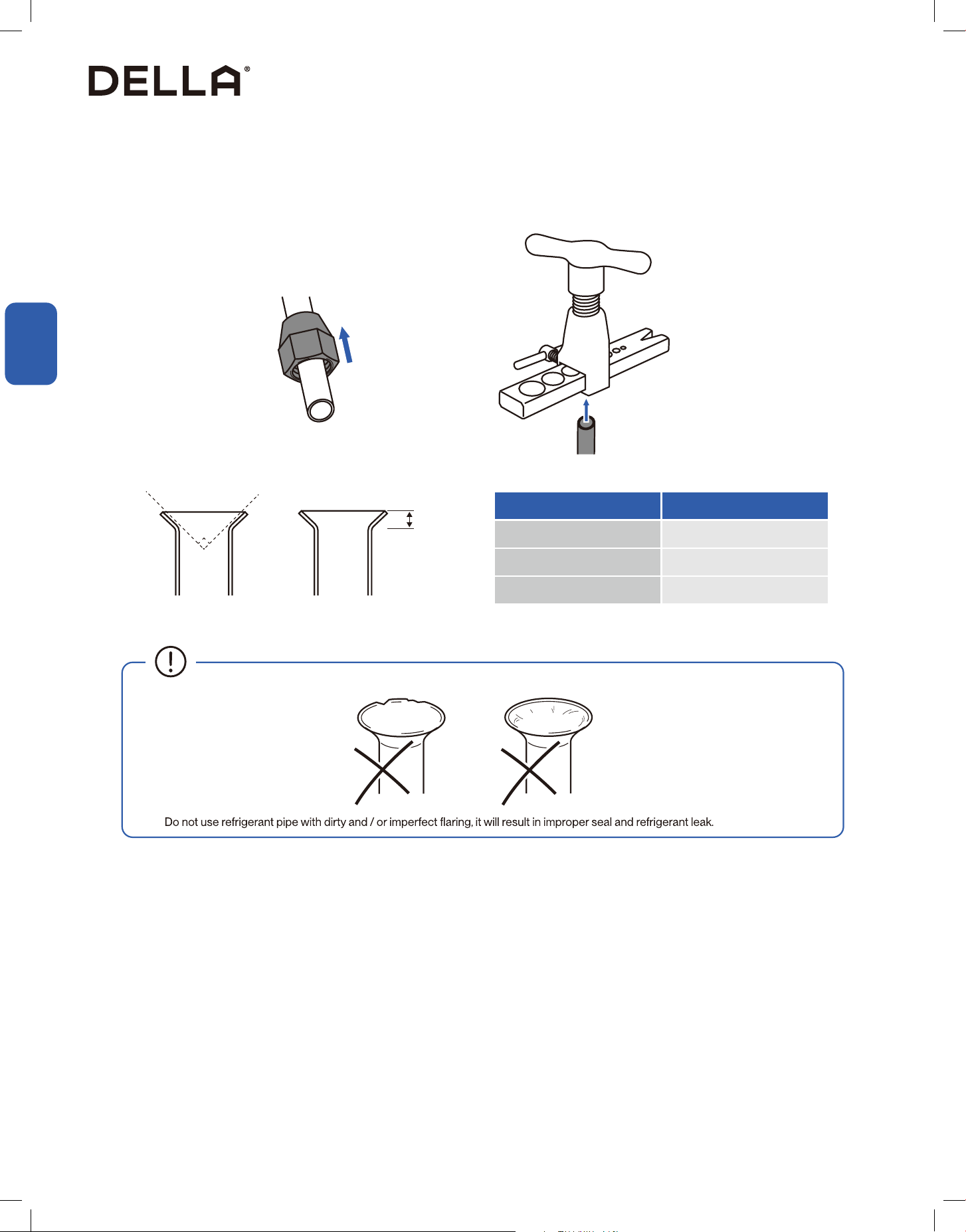
Flaring
For aring connection, aring nut must be installed to the refrigerant pipe before aring the end.
Flaring Size
90°
Outer Diameter Flaring Size
3/8" 0.03" - 0.04"
3/4" 0.02" - 0.03"
7/8" 0.02" - 0.03"
Installation Info
•
58
Installation Info
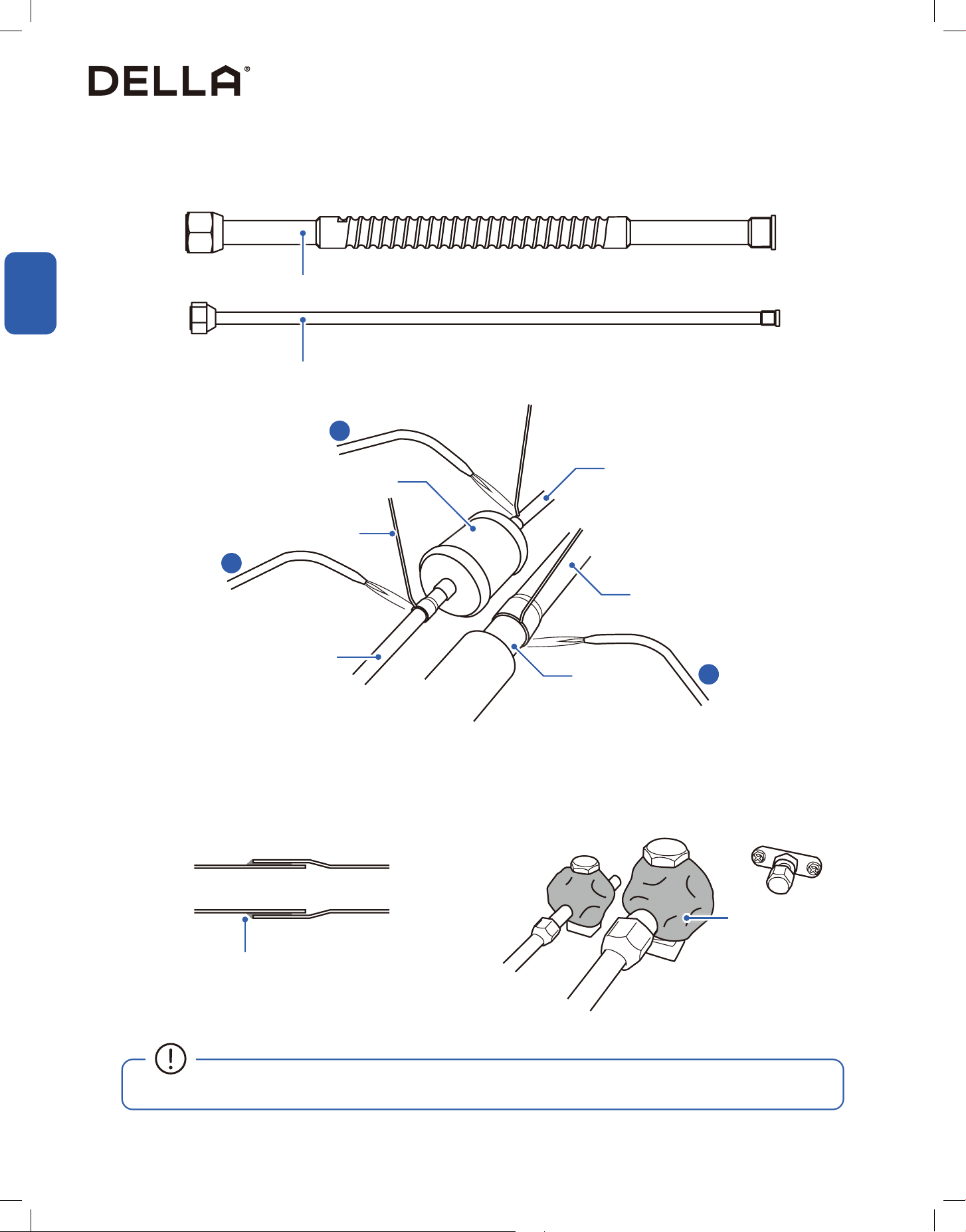
Refrigerant Line Connection and Brazing Preview
• Refrigerant pipes should be connected to the indoor handler unit FIRST, and then connects to the outdoor compressor unit.
• Please refer to your indoor handler unit installation manual for connection instruction.
Liquid Line
Bi-directional Filter Driers
Suction Line
Flare Connection
Braze Connection
Suction Line
Connection Pipe
Liquid Line
Connection Pipe
• Do not install the connecting refrigerant pipe unitl both outdoor compressor and indoor air handler units have been installed.
• Handle the refrigerant pipe with care, any damage, dent, or deform on the pipe would cause refrigerant leak and drastically reduce
CAUTION
Due to the combusive nature of R454B refrigerant, this unit requires connection pipe as an extension for the refrigerant port.
The connection pipes connect to the outdoor unit using are connection, while the rest of the refrigerant line connections will require brazing.
Follow the installation indicated as follow:
14 2
35
59
v.20251118C
Installation
Installation
Installation Info
Refrigerant Line Connection and Brazing
Liquid Line Connection Pipe
1. Connect a bi-directional lter drier (without active alumina) to the liquid line connection pipe.
2. Connect the liquid line to the bi-directional lter.
3. Connect the suction line to the suction line connection pipe.
4. Braze all the connection points. Make sure the brazing material throughly ll in the connection.
Let capillary action draws in the brazing material into the connection
Heat blocking putty
• Place heat blocking putty around refrigerant valve and sensitive sensors before brazing to protect parts from high heat.
Suction Line Connection Pipe
Liquid Line Connection Pipe
Bi-directional lter drier
Liquid Line
to Indoor Unit
Suction Line
to Indoor Unit
Suction Line Connection Pipe
Brazing Alloy
1
2
3
60
Installation
Installation
Installation Info
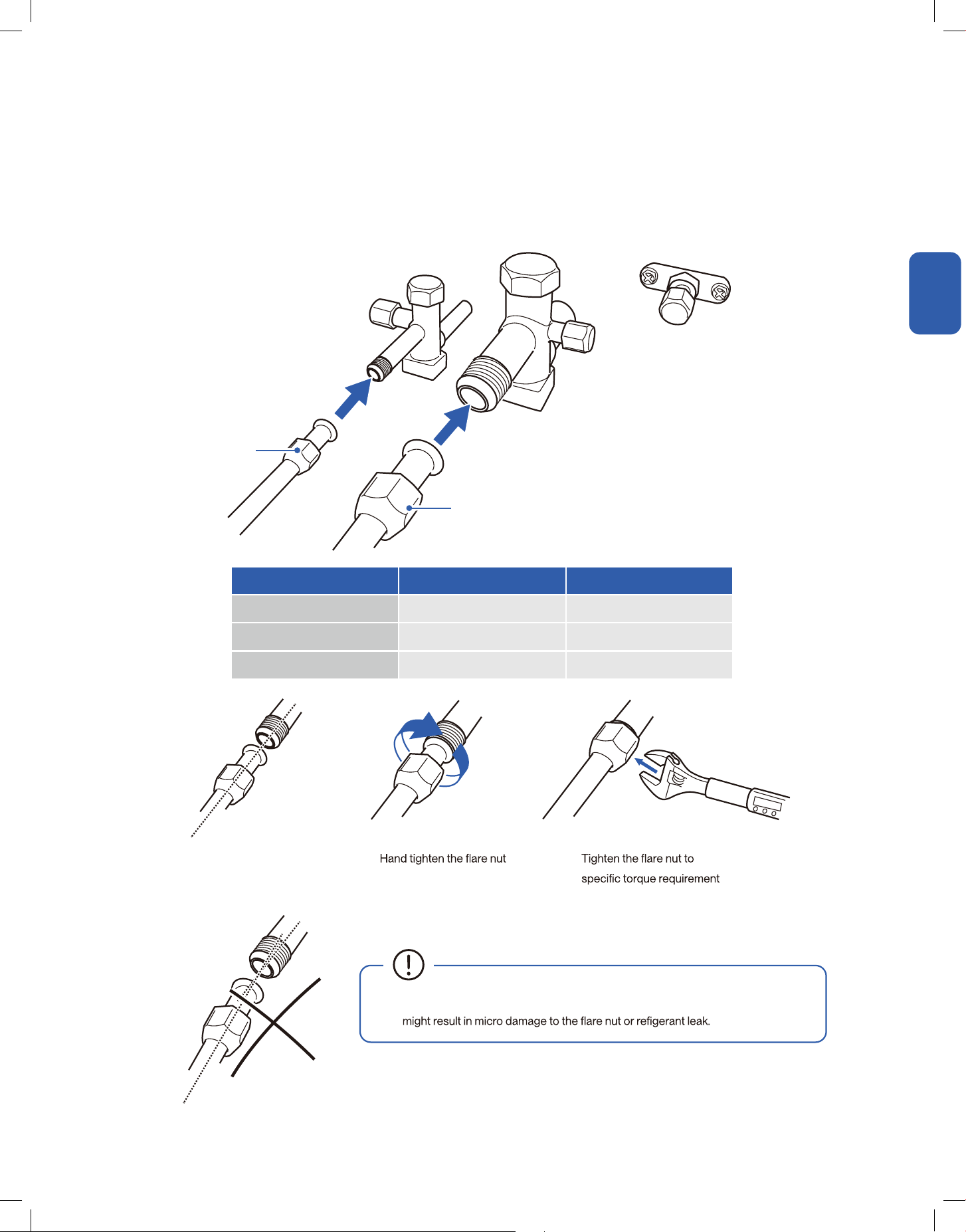
Refrigerant Line Connection and Brazing
• Make sure the connection pipe align straight to the refrigerant port, otherwise it
• Align connection pipe to
refrigerant port
• •
Pipe Size Torque Value (in-lbs) Torque Value (ft-lbs)
3/8" 327 - 372 27.25 - 31
3/4" 620 - 664 51.6 - 55.3
7/8" 690 - 735 57.5 - 61.25
1. Remove the protective caps from the outdoor unit's refrigerant port.
2. Align the connection pipes to the refrigerant port.
3. Tighten the are nut according to the torque requirement as below:
Suction Line
Connection Pipe
Liquid Line
Connection Pipe
61
v.20251118C
Installation
Installation
Installation Info
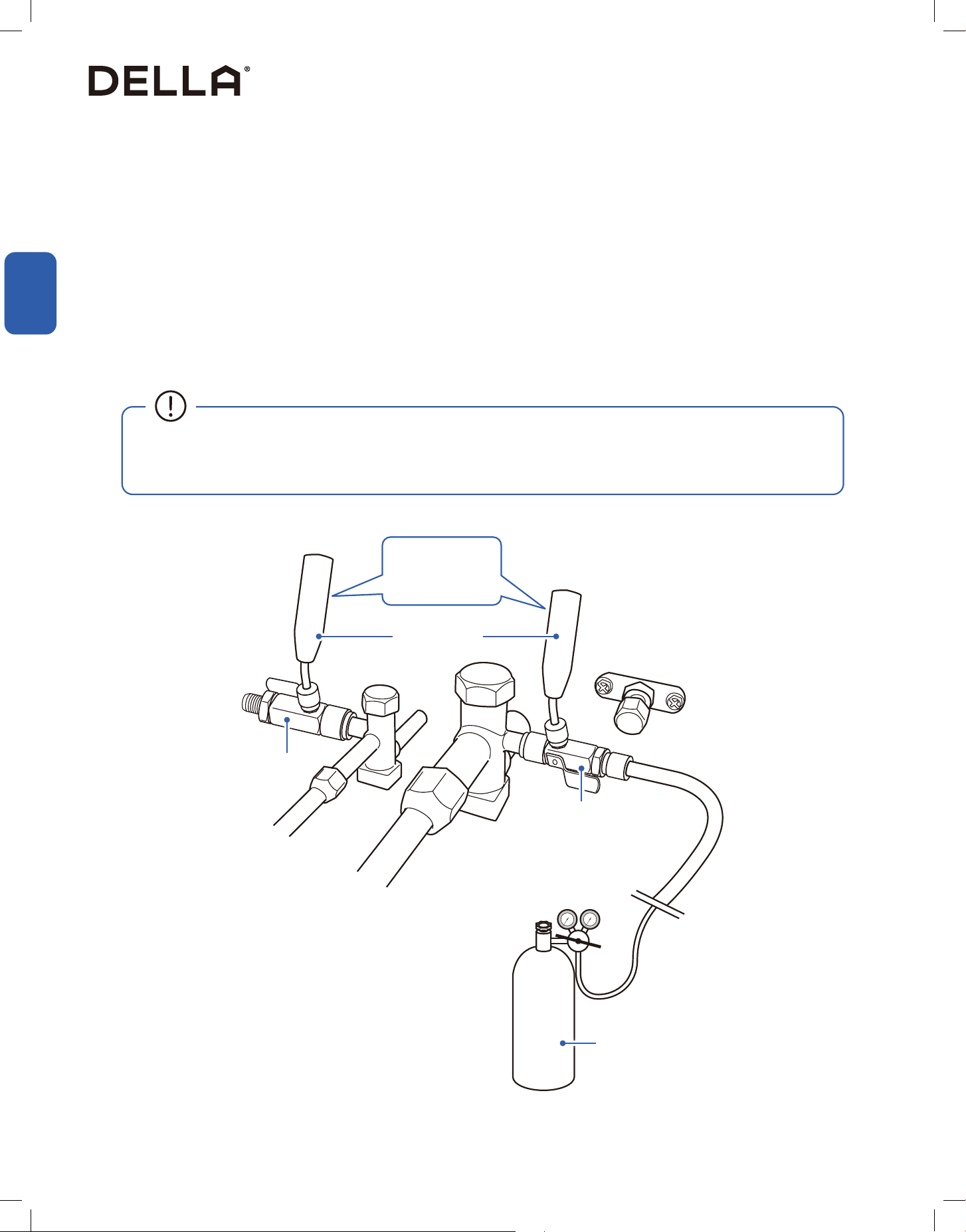
Pressure Check
A nitrogen pressure test should be performed after the refrigerant lineset is brazed in to check there is no leak in the system.
1. Before pressurize the lineset, check if there is any leak on the schrader core.
2. Connect the nitrogen tank to one of the service port, then open all the valve core removal tool ball valve and purge the refrigerant lineset
with nitrogen before pressurizing the lineset.
3. Close the ball valve on the valve core removal tool not connected to the nitrogen tank.
4. With the help of pressure probes / manifold gauges, pressurize the refrigerant line to 250 PSIG.
5. Allow the pressure to stabilize and hold for at least 30 minutes. Check all the connection with bubble test and make sure there is no leak at
any joint.
6. After making sure there is no leak, slowly release nitrogen from the lineset to the air by opening the ball valves on the valve core removal tool.
7. Place schrader cores back into the valves after the pressure test is conducted, and disconnect the dry nitrogen tank from the system
• In the case of a leak, check and
retighten all your pressurizing equipment, including core removal tool, charging hose, and gauges. Cut,
reconnect and braze refrigerant line if necessary. A leak check must be performed again after correction until there is no leak from the
system.
Dry Nitrogen Tank
Valve Core Removal Tool
Valve Core Removal Tool
Pressure Probes
250 PSIG
62
Installation
Installation
Installation Info
Evacuation (Single Hose setup)
1. Attach valve core removal tools to the service ports.
2. Remove the schrader core from the suction line valve.
3. Connect the vacuum hose from the vacuum pump to the valve core removal tool on the suction line valve.
4. Attach a micron gauge to the valve core removal tool on the liquid line valve.
5. Open the ball valve on the suction line side valve core removal tool, and close the ball valve on the liquid line side valve core removal tool.
Turn on the vacuum pump and pull vacuum until the micron gauge display 350 micron or lower.
6. Shut o all ball valves on the valve core removal tools, and turn o the vacuum pump.
7. Leave the system connected with the micron gauge for 15 minutes. Make sure the value does not raise higher than 500 micron.
NOTE: In the case of the value raising above 500 micron, check every joint for any possible source of leak, perform pressure test and
evacuation again after addressing leak source.
8. Once completing vacuum pumping, disconnect the vacuum hose from the AC, and re-attach the telescopic rod with schrader core back into
the valve core removal tool. Make sure the ball valve remain close in this step.
9. Open the ball vavles and screw the schrader cores back into the service port.
10. Detatch the valve core removal tool from the AC and put the service port caps back in place.
Vacuum Pump
350 Micron <500 Micron
Pull Vacuum to Hold Vacuum
Vacuum Hose
Valve Core Removal Tool
Valve Core Removal Tool
Micron Gauge
Suction Line ValveLiquid Line Valve
• Do not remove the valve cap and do not open the refrigerant valves when vacuum pumping the refrigerant line.
63
v.20251118C
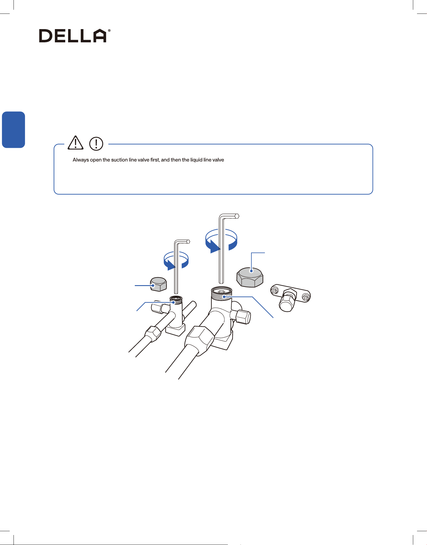
Installation
Installation
Installation Info
Refrigerant Valves
Pressure test and evacuation must be completed before opening the refrierant valves.
1. Remove the refrigerant valve caps.
2. Open the suction line valve. Turn the valve counterclockwise until the valve stem touch the rolled edge.
3. Turn the valve stem back in by about 1/4 to 1/6 turn to prevent leak.
4. Repeat the same procedure for the liquid line valve.
5. Put the refrigerant valve cap back to its original place after releasing refrigerant into the lineset.
1
2
Suction Line Valve
Cap
Cap
Liquid Line Valve
•
• Becareful when opening the liquid line refrigerant valve. Turn the valve step counterclockwise until the valve stem touches the rolled
edge. Do not open the valve stem any further. Failing to follow this will result in abrupt release of refrigerant charge and may lead to
injury or property damage.
CAUTION
64
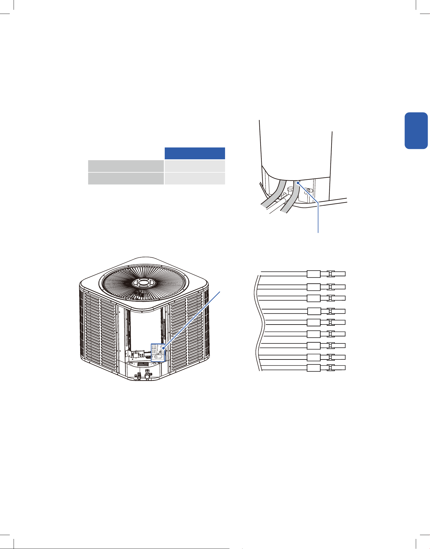
Installation
Installation
Installation Info
Low Voltage Wire Connection
The maximum length of low voltage wiring should be dene as the length from the outdoor unit to the indoor handler unit and the thermostat.
Field installed electrical conduit is required at low voltage wire entry point. Animals such as frogs, snakes, spiders and other natural elements may
get into the control box and damaging the PCB. Manufacturer reserves the right to reject warranty claim on PCB if installation requirements are
not comply.
Class 2 low voltage wiring should not be run in conduit with main power wiring and must be seperated from power wiring, unless class 1 wire of
proper voltage rating is used.
• Low voltage control wiring should be color coded 18 AWG.
• Refer to wiring diagrams attached to indoor and outdoor sections to be connected.
• Make sure separation of control wiring and power wiring has been maintained.
Seal to the wiring entry point
Thermostat wiring harness
CN27
Control Wiring
Wire Size 18 AWG
Max. Wire Length 164ft
R
C
D
T
DHM
L
O
Y2
Y0
65
v.20251118C
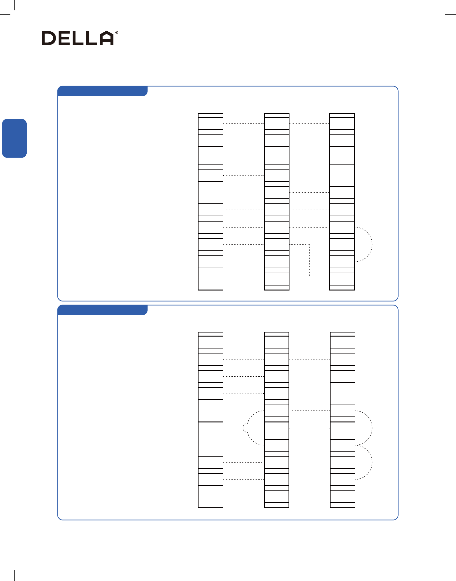
2 Stages, 2 Step, Heat Pump
2 Stages, 2 Step, Cooling Only
Thermostat
Thermostat
R
R
R
R
R
R
C
C
C
C
C
C
G
G
G
G
G
G
D
D
D
D
W2
W2
DHM
DHM
W2
W1
W1
T
T
W1
W1
W2
O
O
O
O
O
Y2
Y2
Y2
Y2
Y2
Y2
Y0
Y0
Y0
Y0
Y1
Y1
Y
Y
RED
RED
RED
RED
BLUE
BLUE
BLUE
BLUE
GREEN
GREEN
GREEN
GREEN
YELLOW
YELLOW
GRAY
GRAY
GRAY
GRAY
YELLOW&RED
YELLOW&RED
BLUE&WHITE
BLUE&WHITE
YELLOW&RED
YELLOW&RED
ORANGE
ORANGE
ORANGE
ORANGE
BLACK
BLACK
WHITE
WHITE
BROWN
BROWN
PURPLE
PURPLE
PURPLE
PURPLE
Air Handler
Air Handler
Outdoor Unit
Outdoor Unit
24V AC Hot
24V AC Hot
24V AC Common
24V AC Common
Fan
Fan
Cool / Heat 1st Stage
Cool / Heat 1st Stage
Cool / Heat 2nd Stage
Cool / Heat 2nd Stage
SOV
SOV
Emergency Heat 1st Stage /
Emergency Heat 1st Stage /
Emergency Heat 2nd Stage /
Heat 3rd Stage
Heat 4th Stage
Hea
t 4th Stage
Installation
Installation
Installation Info
Low Voltage Wire Connection
66
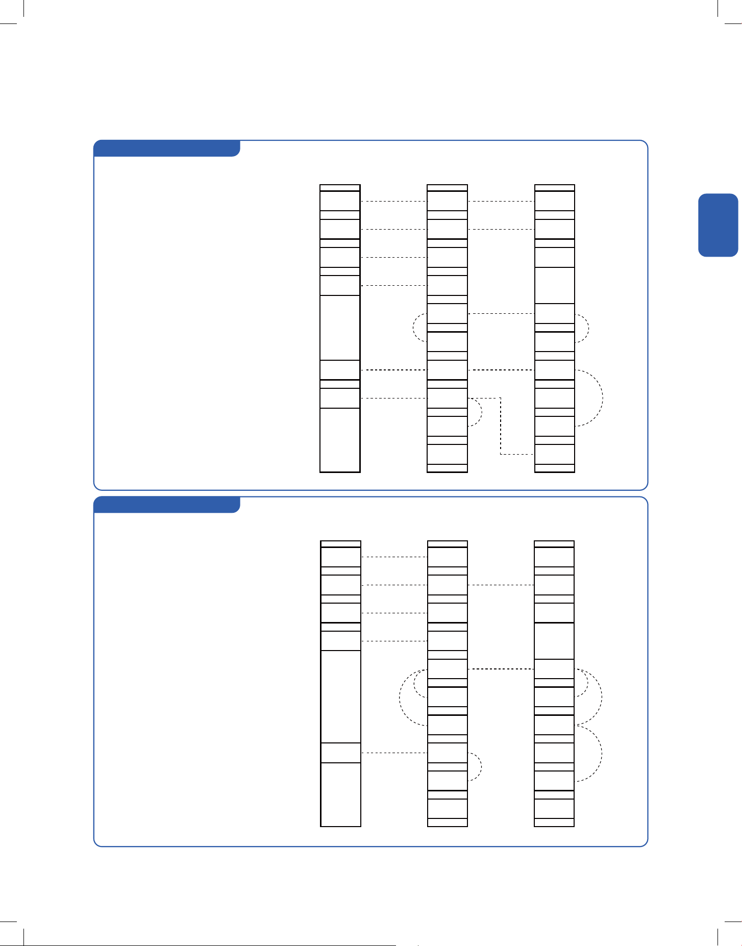
Single Step, Heat Pump
Single Step, Cooling Only
Installation
Installation
Installation Info
Low Voltage Wire Connection
Thermostat
Thermostat
R
R
R
R
R
R
C
C
C
C
C
C
G
G
G
G
G
G
D
D
D
D
W2
W2
DHM
DHM
W2
W2
W1
W1
T
T
W1
W1
O
O
O
O
O
O
Y2
Y2
Y2
Y2
Y0
Y0
Y0
Y0
Y1
Y1
Y
Y
RED
RED
RED
RED
BLUE
BLUE
BLUE
BLUE
GREEN
GREEN
GREEN
GREEN
YELLOW
YELLOW
GRAY
GRAY
GRAY
GRAY
YELLOW&RED
YELLOW&RED
BLUE&WHITE
BLUE&WHITE
YELLOW&RED
YELLOW&RED
ORANGE
ORANGE
ORANGE
ORANGE
BLACK
BLACK
WHITE
WHITE
BROWN
BROWN
PURPLE
PURPLE
PURPLE
PURPLE
Air Handler
Air Handler
Outdoor Unit
Outdoor Unit
24V AC Hot
24V AC Hot
24V AC Common
24V AC Common
Fan
Fan
Cool / Heat 1st Stage
Cool / Heat 1st Stage
SOV
SOV
Emergency Heat 1st Stage /
Emergency Heat 1st Stage /
Emergency Heat 2nd Stage /
Emergency Heat 2nd Stage /
Heat 3rd Stage
Heat 3rd Stage
Heat 4th Stage
Heat 4th Stage
67
v.20251118C
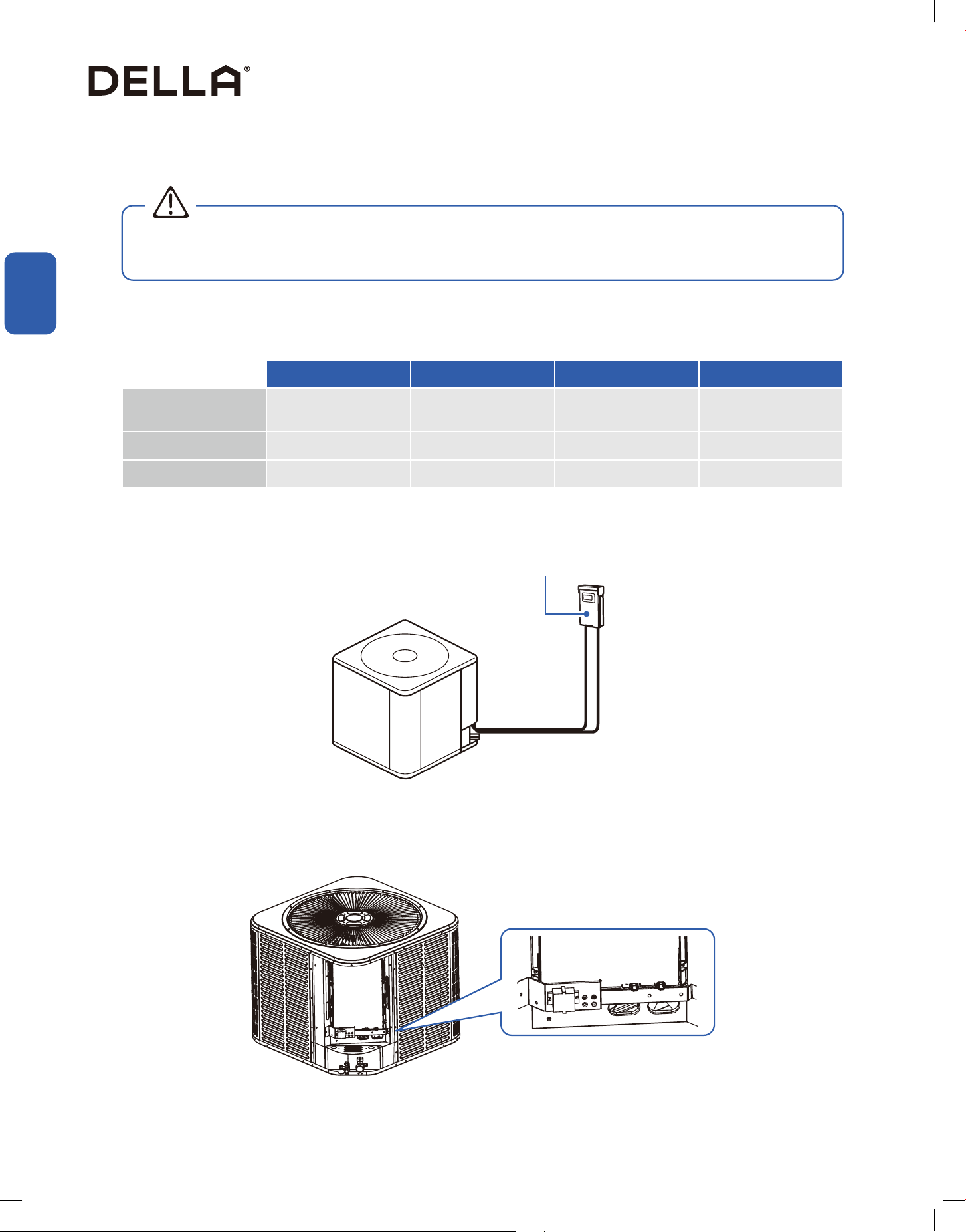
Installation
Installation
Installation Info
High Voltage Power Supply
High Voltage Disconnect Switch
High Voltage Grounding
• Follow all electrical safety precausions when installing, testing, servicing, and troubleshooting this product. Failing to follow precautions
when working with live electrical components could result in death or serious injury.
WARNING
The power supply must corresponds to that stamped on the rating plate.
Power wiring must comply with national, state, and local codes.
Locate and follow the wiring diagram printed on the inside of the control box cover.
Install an independent disconnect switch at the outdoor unit. Field provided exible electrical conduit must be used for high voltage wiring.
The outdoor compressor must be grounded to prevent
048-T-24K-ODU 048-T-36K-ODU 048-T-48K-ODU 048-T-60K-ODU
Power Supply
208 V - 230 V / 60 Hz
/ 1P
208 V - 230 V / 60 Hz
/ 1P
203 V - 230 V / 60 Hz
/ 1P
208 V - 230 V / 60 Hz
/ 1P
Min. Circuit Ampacity 16 A 22 A 35 A 35 A
Breaker Size 25 A 35 A 60 A 60 A
Disconnect Switch
68

Installation
Installation
Installation Info
Wiring Reference
The ampacity shown apply to appliance wiring materials with insulation rated not less than 194°F / 90°C.
Supply circuit power wiring must be 167°F / 75°C minimum copper conductors only.
Wiring Material Ampacity AWG
4 22
7 20
10 18
13 16
18 14
25 12
30 10
40 8
55 6
70 4
69
v.20251118C
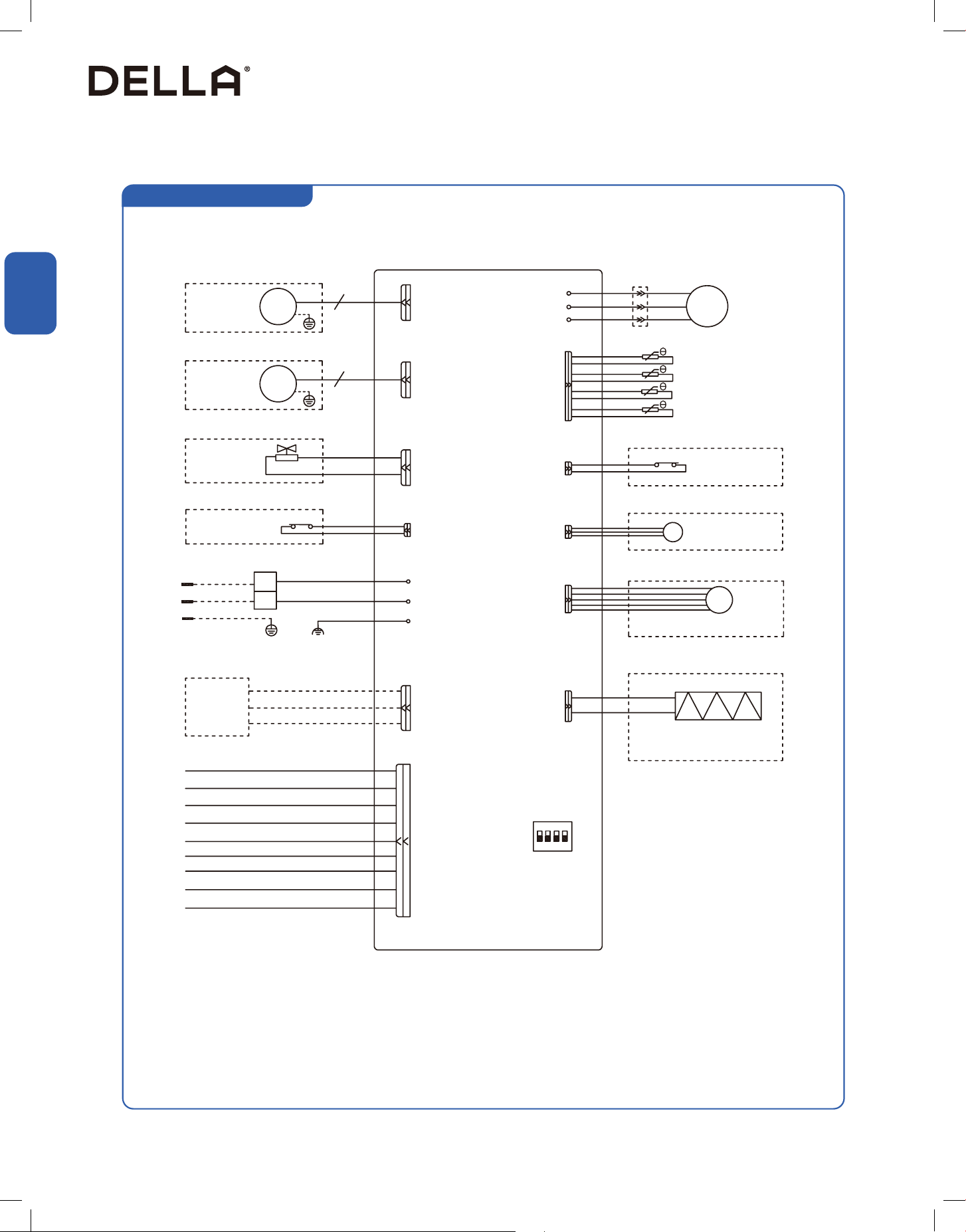
Installation
Installation
Installation Info
Circuit Diagram
048-T series ODU
Fan Motor 1
Fan Motor 2
Valve
Low Pressure Switch
Power Supply
RS485
To Indoor
Ground
L1
L2
(Optional)
(Optional)
(Optional)
(Optional)
(Optional)
PCB
DC FAN
U
U
V
W
Red
White
Liquid Line Temp. Sensor
Environment Temp. Sensor
Pipe Temp. Sensor
Exhaust Temp. Sensor
High Pressure Switch
High Pressure Sensor
Electronic Expansion Valve
Heater
(Optional)
(Optional)
(Optional)
(Optional)
Blue
Red
White
Blue
V
W
CN2 / CN1
HP / HP1
SHP
CN7
HEAT
HEAT 1
CN11
SP
EEV
DC
MOTOR
DC
MOTOR
CN12-2
P10
P8 (VAL)
LP/LP1
L1 (AC_N)
RS485
R
C
Yo
Y2
O CN27
D
L
DHM
T
Red (Blue)
Red
Blue
Gray
Yellow & Red
Orange
Purple
White
Brown
Blue & White
Black (Brown)
GNYE (GN)
L2 (AC_L)
P0 (GND) / Ground
GNYE
GNYE
SW1
1 2 3 4
Default
COMP
70
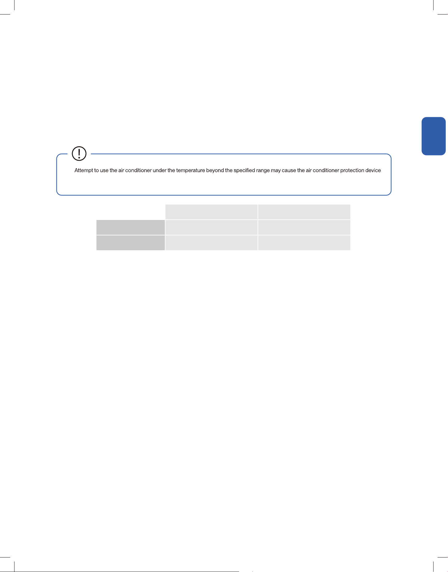
Installation
Installation
Installation Info
Test Run and Start Up
After the complete installation, including the indoor air handler and thermostat, test run the system and take sure it performs and works properly
without water leak or abnormal noise.
When restarting the air conditionier after shutting down, or switching between heat and cool mode during operation, the air conditioner protection
device will triggered. The compressor will resume normal operation after 3 minutes.
When using heating mode, the indoor air handler may take 2 - 5 minutes for preheating before the air conditioner will start heating and blows
warm air.
During heating mode, if the outdoor unit is frosted, the air conditioner will enable the automatic defrosting cycle to improve the heating eect.
During defrosting, the indoor and outdoor fans stop running. The air conditioner will resume heating automatically after defrosting is nsihed.
1. Set the thermostat to OFF.
2. Turn ON the disconnect switch to apply power to the system.
3. Wait an hour before turning on the unit if the out
door embient temperature is <59°F.
4. Set the thermostat to ON.
•
to start and prevent the system from operating normally. Therefore, test run and use the air conditioner in the following temperature
conditions:
Indoor Temperature Outdoor Temperature
Cool / Dehumidify Mode 63°F - 90°F / 17°C - 32°C 5°F - 125°F / -15°C - 52°C
Heat Mode 32°F - 86°F / 0°C - 30°C -20°F - 27°F / -20°C - 27°C
71
v.20251118C
System Info
System Info
System Info
Default Display
DSP1-1, DSP1-2 Code
LED on main control board can display the operating status of the outdoor unit.
DSP1-1, DSP1-2: Normally blank, but it will display codes accordingly if there is
damaged sensor and command response. See the below table for details.
DSP1-3: If displays outdoor unit's operation mode.
DSP1-1 DSP1-2 DSP1-3
Error Code Description
E0 Indoor and outdoor communication failure
E1 Indoor environment temperature sensor failure
E2 Indoor coil temperature sensor failure
E3 Outdoor coil temperature sensor failure
E4 System abnormalities (low refrigerant)
E5
E6 Indoor PG / DC fan failure
E7 Outdoor environment temperature sensor failure
E8 Outdoor exhaust temperature sensor failure
E9
Outdoor IPM module failure / compressor drive
failure
EA Outdoor current sensor failure
Eb
Main control board and display screen
communication error
EC Outdoor module communication failure
EE Outdoor EEPROM failure
EF Outdoor DC fan failure
Error Code Description
EH Outdoor air intake sensor failure
EP Outdoor compressor shell top failure
EU Outdoor voltage sensor failure
EJ Outdoor middle coil temperature sensor failure
En Outdoor air pipe temperature sensor failure
Ey Outdoor liquid pipe temperature sensor failure
P0 IPM module protection
P1 Over and under voltage protection
P2 Overcurrent protection
P3 Other protections
P4 Outdoor exhaust temperature too high protection
P5 Refrigeration anti-freezing protection
P6 Refrigeration anti-overheating protection
P7 Heating anti-overheating protection
P8 Outdoor temperature too high or too low protection
72
System Info
System Info
System Info
DSP1-1, DSP1-2 Code
Error Code Description
P9 Compressor drive protection (load abnormaility)
PA
Top outlet wind plate communication fault / mode
F0 Red exterior motion sensor failure
F1 Electricity module failure
F2 Exhaust temperature sensor bag failure protection
F3 Outer pipe temperature sensor bag failure protection
F4 Refrigerant circuit abnormal protection
F5 PFC protection
F6 Compressor missing / reverse phase protection
F7 Module temperature protection
F8 Four-way valve reversing abnormal protection
F9 Module temperature sensing circuit failure
FA Compressor phase current detection failure
Fb Refrigeration and heating overlaod protection
FC Reduced frequency power overload protection
Error Code Description
FE
Reduced / frequency module current (compressor
phase current) protection
FF Reduced / frequency module temperature protection
FH Reduced / frequency drive protection
FP Dewdrop protection
FU Frost protection
FJ Reduced / frequency exhaust protection
Fn
Reduced / frequency external machine AC current
protection
Fy
H1 High pressure switch failure
H2 Low pressure switch failure
H3 High pressure sensor failure
H4 Low pressure sensor failure
Hd Indoor refrigerant leakage protection
73
v.20251118C
System Info
System Info
System Info
DSP1-3 Code
Dip Switches setting
DSPI-3
Code
Description
0 Standby
1 Ready
2 Cooling
3 Heating
4 Oil Return Operation
5 Defrosting Operation
6 Forced Deforsting
7 Forced Cooling Operation
8 Forced Heating Operation
A Fault
H
SW1 Dip Switch Description
No. Setting item Status Content
SW1-1 SIngle Cooling / Heat Pump
ON AC outdoor unit
digit HP outdoor unit
SW1-2 Operating Capacity
ON Lower capacity
digit Normal capacity
SW1-3 Control Mode
ON 485 communication
digit 24V ON / OFF control
SW1-4 Keep the factory decaults
SW1-1 ~ SW1-4
DIP switch should be checked once when the main control is powered on.
74
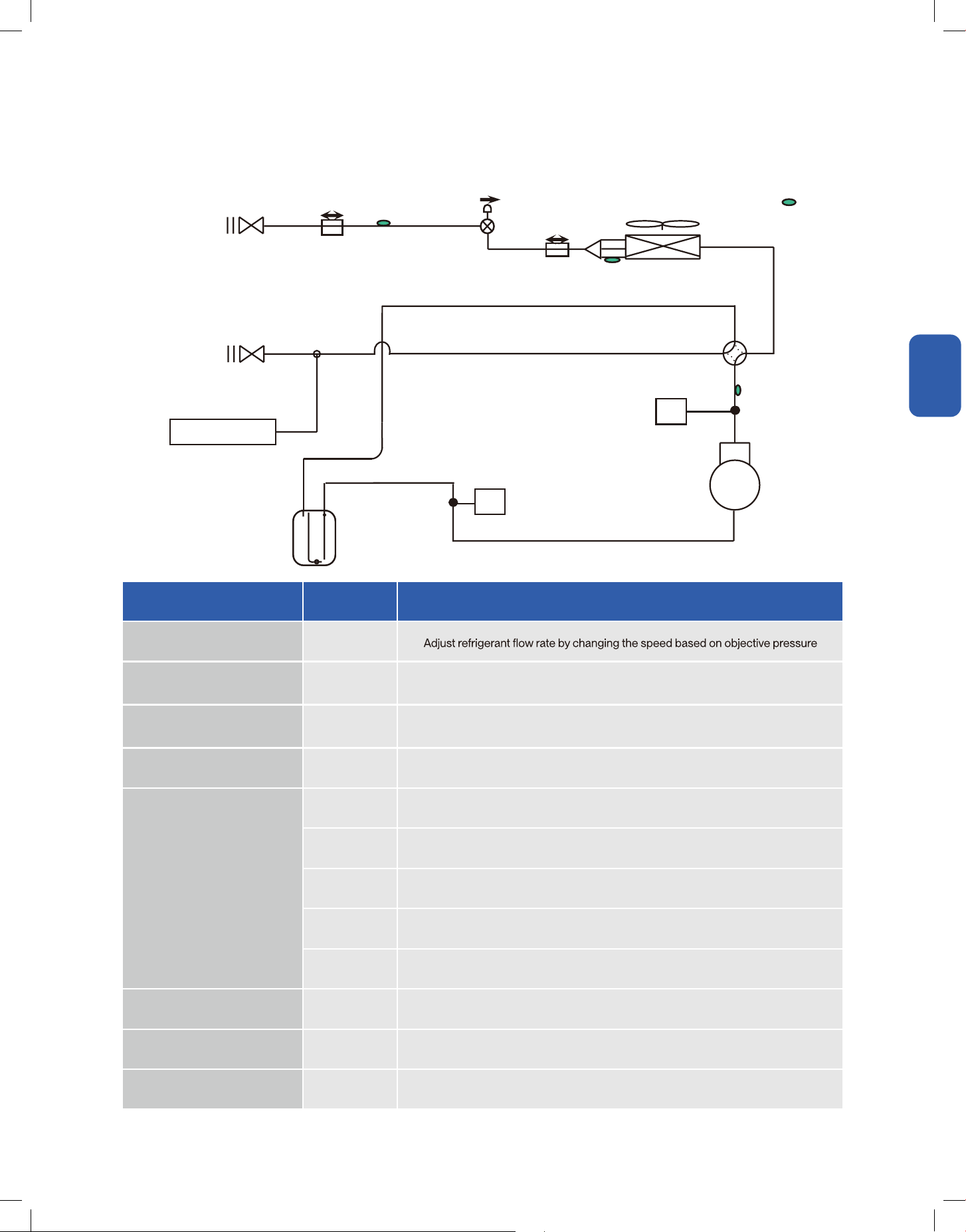
System Info
System Info
System Info
Major Components Function
Name Symbol Function
Inverter Compressor INV
DC Motor FAN
Outputs heat exchanger capacity by adjusting the motor rotational speed based on
operating pressure
Electronic Expansion Valve EEV
1. Fully open in cooling mode and defrost operation
2. Control compressor discharge superheat in heating mode
Reversing Valve ST1 (RV) Switches the operation mode between heating and cooling (including defrost control)
Temperature Sensor
TH Uses to control defrost during heating operation
TA Uses to detect outdoor air temperature and control fan speed
TL Uses to detect liquid line temperature and calculate sub-cooling
TD Uses to detect compressor discharge temperature and calculate discharge superheat
TF Uses to detect heatsink temperature of inverter module
High Pressure Switch HP Uses to detect high pressure
Low Pressure Switch LP Uses to detect low pressure
Accumulator ACC To prevent the compressor from ingesting liquid refrigerant
Pressure Sensor
Gas Service Valve
Heat ExchangerTH
EEV
FAN
TA
TL
Liquid Service Valve
ACC
LP
INV
HP
TP
STI
(RV)
75
v.20251118C
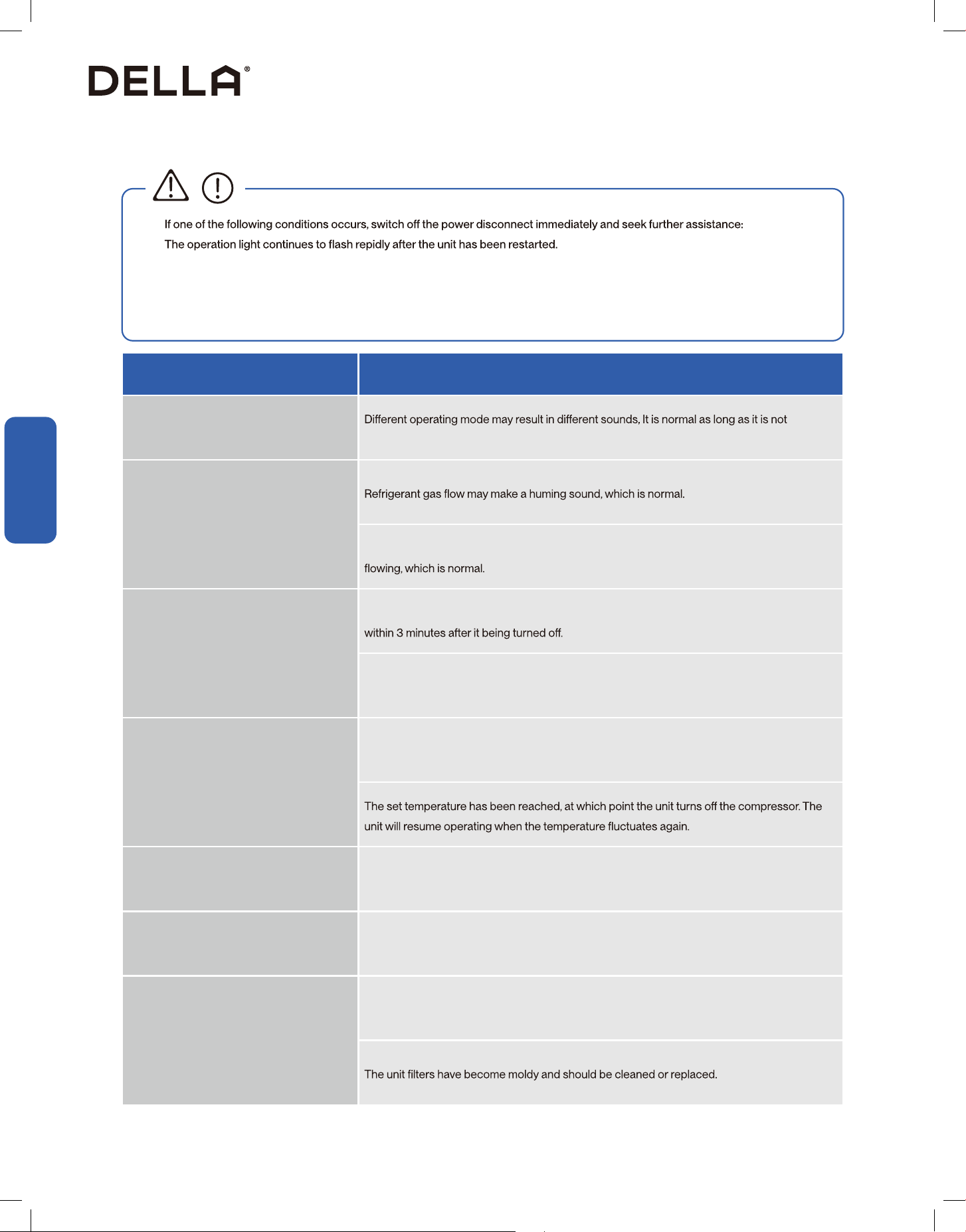
Troubleshooting
Having Problems?
Having Problems?
•
•
• The unit continually trips fuses or circuit breakers.
• A foreign object or water enters the air conditioner.
• The indoor unit leaks
• Other abnormal situations
CAUTION
When Problem Possible Cause / Explanation / Solution
Abnormal noises from the outdoor unit
abnormally loud.
Noises from both indoor and outdoor unit
A hissing sound could be heard when the AC enter defrost mode and stop refrigerant gas from
Unit does not turn ON
The unit has a 3 minutes protection that prevent it from overloading. It cannot be restarted
Cooling and Heating mode: If the operation light and PRE-DEF (pre-heating / defrost) indicators
are lit, the outdoor temperature is too cold, the unit will attempt to defrost before operating
normaly.
The unit changes from cool mode to fan
mode
The unit changes its setting to prevent frost from forming on the unit. Once the temperature
increases, the unit will start operating again.
Both the indoor and outdoor unit emit white
mist
When the unit restart in heat mode after defrosting, white mist may be emitted due to moisture
generated from the defrosting process.
Dust is emitted from either the indoor or
outdoor unit
The unit may accumulate dust during extended periods of non use, which will be emitted when
the unit is turned on. This can be mitigated by covering the unit during long periods of inactivity.
The unit emits a bad odor
The unit may abosrb odors from the environment (such as furniture, cooking, cigarettes, etc.)
which will be emitted during operations.
76

Troubleshooting
Having Problems?
Having Problems?
When Problem Possible Cause / Explanation / Solution
The outdoor unit fan does not operate In normal operation, the fan speed is controlled to optimize product operation.
The unit is not working
Power failure. Restore power supply and restart the unit again.
The power switch is OFF, Turn the power back ON and restart the unit.
Breaker has been triggered. Reset the breaker.
The unit's 3 minutes protection has been triggered. Wait 3 minutes and restart the unit.
Poor cooling performance
Temperature setting may be higher than the ambient room temperature. Lower the temperature
setting.
Doors or windows are open. Close the door or windows while operating the AC
Excessive heat is generated by sunlight. Close windows and curtains to block sunlight
generated heat.
Low refrigerant due to leak or long-term use. Contact HVAC technician and check on
refrigerant level. Re-charge the system if necessary.
Poor heating performance
The outdoor temperature is lower than operational temperature
Cold air is entering through doors and windows. Close the door or windows while operating the
AC
Low refrigerant due to leak or long-term use. Contact HVAC technician and check on
refrigerant level. Re-charge the system if necessary.
77
v.20251118C
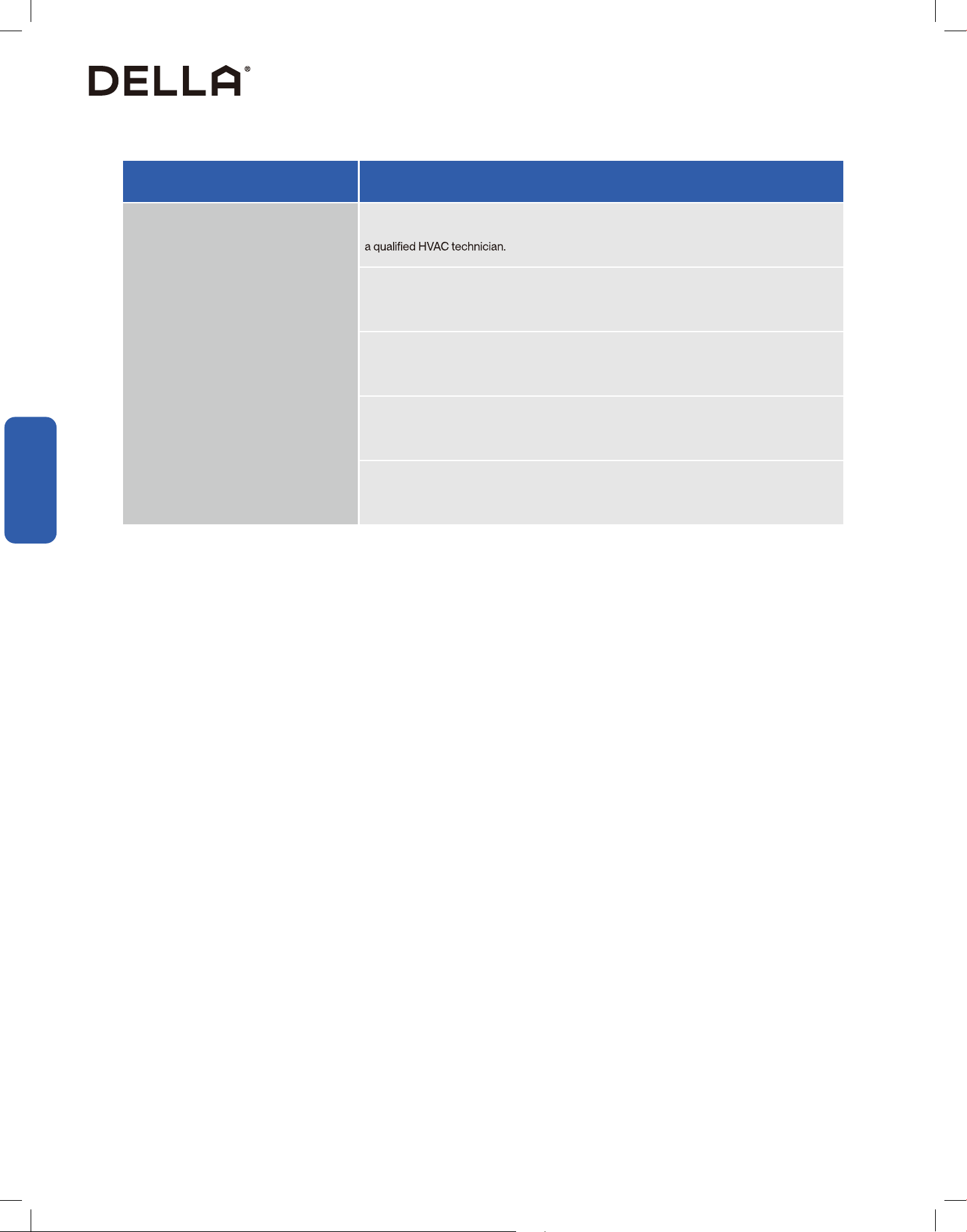
Troubleshooting
Having Problems?
Having Problems?
When Problem Possible Cause / Explanation / Solution
The unit starts and stops frequently
There is too much or too little refrigerant in the system. Check and adjust the refrigerant level by
The refrigerant lineset is contaminated by air or water vapor. Recover all the refrigerant from the
system, then evacuate and recharge refrigerant.
System circuit malfunctioned. Check the circuit and replace malfunctioning piece of equipment.
Malfunction compressor. Repair or replace the compressor
The voltage is too high or too low, or unstable voltage. A minostatic might need to be installed to
regulate the voltage.
78
© Della All rights reserved.
notice for product improvement. Any updates to the manual will be
uploaded to the della website.
www.dellahome.com
support@dellahome.com
800 863 4143
6:00 a.m. 4:00 p.m. PST Monday Friday