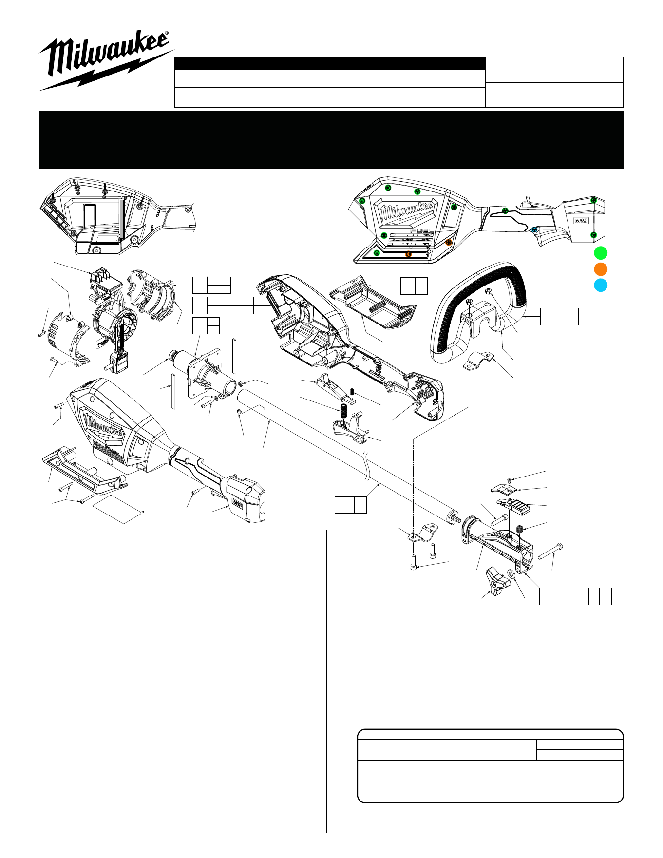
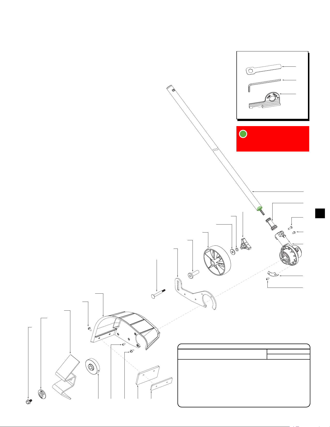
M18 FUEL™ QUIK-LOK™ POWER HEAD
2825-20
K49A
54-49-2810
See Page 15
Oct. 2024
REVISED BULLETIN
SERVICE PARTS LIST
BULLETIN NO.
WIRING INSTRUCTION
DATE
SPECIFY CATALOG NO. AND SERIAL NO. WHEN ORDERING PARTS
CATALOG NO.
FIG. PART NO. DESCRIPTION OF PART NO. REQ.
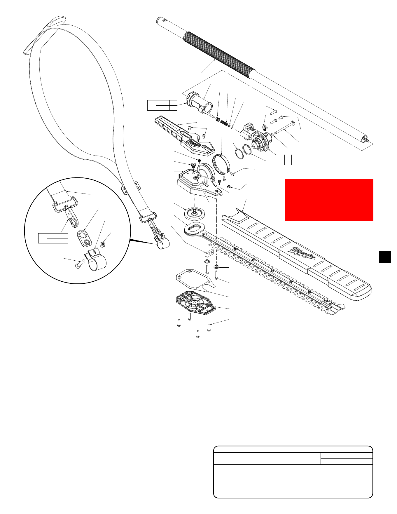
8 --------------- Motor Insulator - Right (1)
9 06-82-0180 M3 x 14mm Pan Hd. ST T-10 Screw (6)
10 --------------- Lower Cover Halve - Right (1)
11 05-88-1300 M4 x 28mm Pan Hd. ST T-20 Screw (2)
12 05-88-5375 M4 x 13.5 Pan Hd. ST T-20 Screw (1)
13 --------------- Housing Cover - Right Housing Halve (1)
14 05-88-1200 M4 x 16mm Pan Hd. ST T-20 Screw (11)
15 05-74-0015 M6 x 21.5mm, 5mm Hex socket Cap Screw (4)
19 44-60-0068 Clamping Knob (1)
20 --------------- Quick Release Casting (1)
21 40-50-1090 Spring (1)
22 05-78-0027 M6 x 50mm Hex Hd. Machine Screw (1)
23 45-72-0013 Quick Change Trigger (1)
24 05-81-0592 M4 x 6.5mm Flat Head T-15 Screw (1)
25 42-92-0047 Trigger Cover (1)
26 05-74-0026 M6 x 30mm Cap Hd. Hex Socket Screw (1)
29 42-68-0292 Carrier Handle Clip (2)
30 05-55-0006 M6 Hex Nut (2)
31 --------------- Carrier Handle (1)
32 45-72-0083 On-OTrigger (1)
33 40-50-0374 Bias Spring (1)
34 40-50-0373 Spring (1)
39 06-82-5270 6-32 x 1/4" Pan Hd. Tapt. T-15 Screw (1)
40 05-74-0012 M4 x 20mm Pan Hd. T-20 Machine Screw (1)
41 45-88-0825 Flat Washer (1)
42 05-55-0004 M4 Hex Nut (1)
45 06-82-7240 6-19 x 1/2" Pan Hd. ST T-15 Screw (4)
46 44-52-0001 Rubber Pad with Adhesive (Set of 2) (1)
47 --------------- Lower Cover Halve - Left (1)
48 --------------- Housing Support - Left Housing Halve (1)
49 --------------- Motor Insulator - Left (1)
51 02-04-0034 Ball Bearing (1)
76 45-88-0011 Flat Washer (1)
83 12-20-0156 Service Nameplate (1)
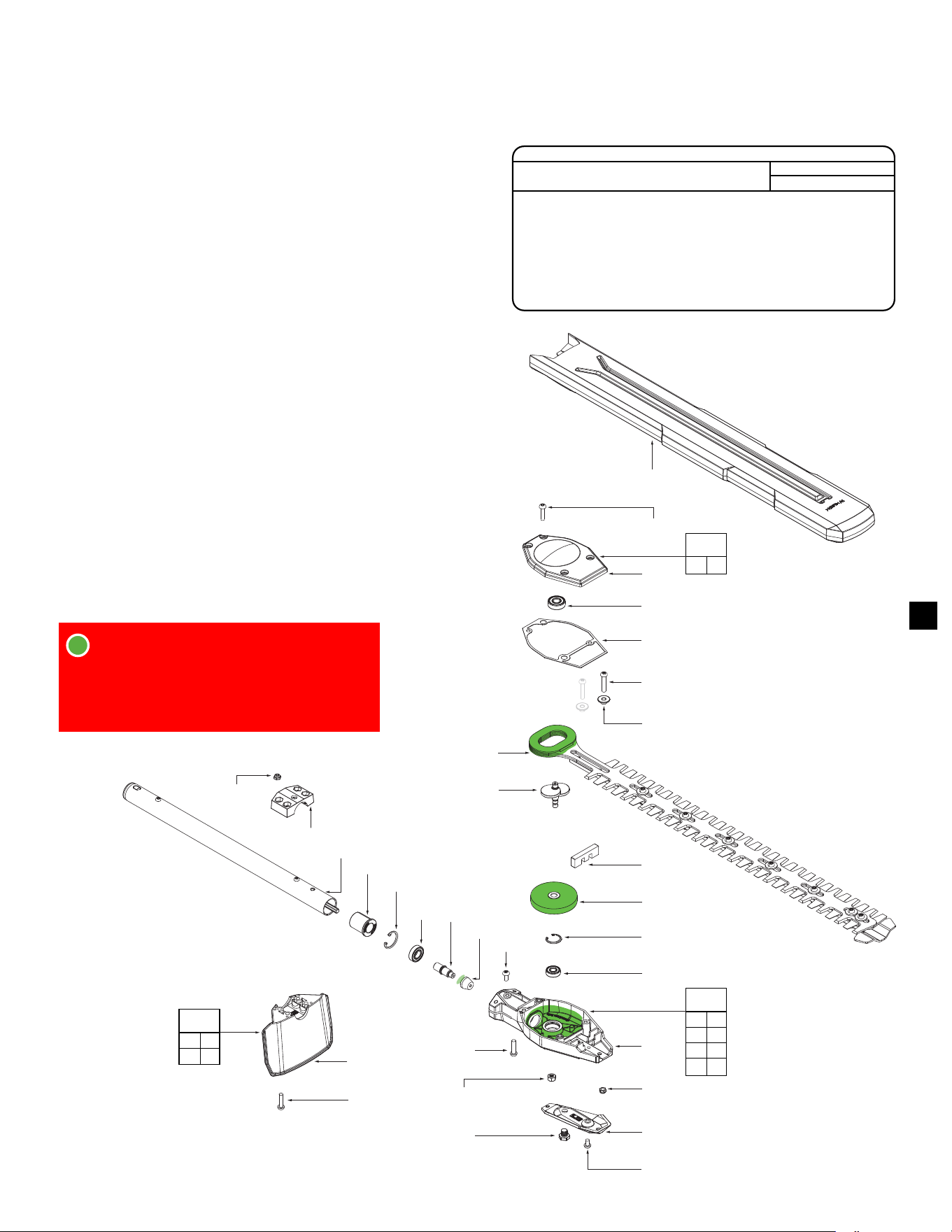
Pg. 1 Power Unit
Pg. 2 Edge Trimmer Attachment
Pg. 3 String Trimmer Attachment
Pg. 4 Hedge Trimmer Attachment
Pg. 5 Pole Saw Attachment
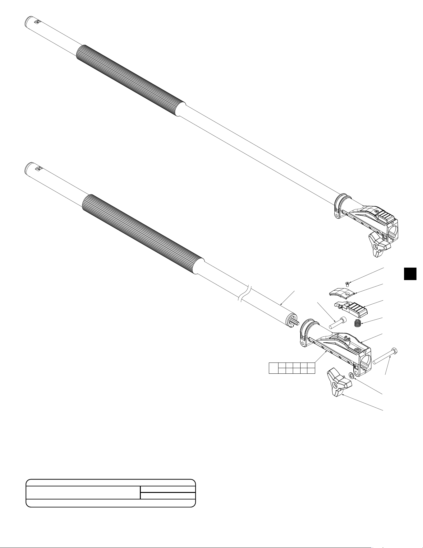
Pg. 6 Extension Tube Attachment
Pg. 7 Brush Cutter Attachment
Pg. 8 Rubber Broom Attachment
Pg. 9 Bristle Brush Attachment
Pg. 10 Cultivator Attachment
14 11x
12 1x
11 2x
Rubber Pads with adhesive
(46) are to be placed in both
Housing Halves (13 and 48).
90
8
9
(6x)
45
(4x)
14
(11x)
10
11
(2x)
83 12 13
51
46
(2x)
41
40
39
97
29
15
(2x)
20
76
26
30
(2x)
31
29
34
48
32
96
33
42
49
47
11 12 13 14
46 48 83
91
8 9
49
93
51
94
10
47
92
15 29
30 31
95
24
25
23
21
22
97
98
100
19 20 21 22 23
24 25 26 76
98
19
FIG. PART NO. DESCRIPTION OF PART NO. REQ.
90 14-20-0078 Electronics Assembly (1)
91 31-44-0156 Housing Kit (1)
92 31-44-0181 Lower Cover Kit (1)
93 31-50-0023 Motor Insulator Kit (1)
94 16-01-0036 Rotor/Motor Mount Assembly (1)
95 14-34-0124 Carrier Handle Assembly (1)
96 45-72-0036 Lock-OTriggerAssembly (1)
97 45-08-0031 Drive Shaft Assembly (For Power Unit) (1)
98 14-02-0010 Quick Release Assembly (1)
100 43-24-2825
Drive Shaft/Quick Release Assy. (Power Unit)
(1)
10-20-1788 Warning Label (Not Shown) (1)
10-20-1789 Warning Label (Not Shown) (1)
SCREW TORQUE SPECIFICATIONS
SEAT TORQUE
FIG. PART NO. WHERE USED (kgf-cm) (lb-in)
9 06-82-0180 Motor Insulator 8-12 7-10
26 05-74-0026 Quick Release Casting 45-50 39-43
40 05-74-0012 Motor Mount 11-14 9-12
45 06-82-7240 Motor Insulator 12-16 10-13
SERIAL NO.
MILWAUKEE TOOL
l
www.milwaukeetool.com
13135 W. LISBON RD., BROOKFIELD, WI 53005
Drwg. 12
Pg. 11 Blower Attachment
Pg. 12 Bed Redener Attachment
Pg. 13 Short Shaft Hedge Trimmer
Pg. 14 Reciprocator Attachment
Pg. 15 Wiring Diagram
25
1
2
3
6
(2x)
4
6
(2x)
8
7
(3x)
9
11
17
16
15
14
13
19
18
7
10
6
12
(2x)
30
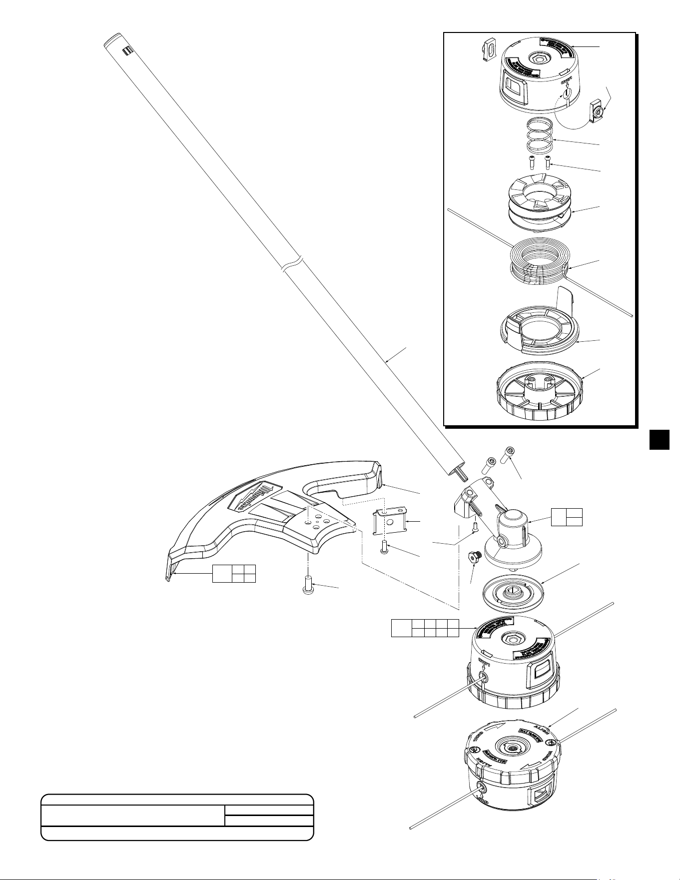
FIG. PART NO. DESCRIPTION OF PART NO. REQ.
1 45-04-0016 M8 x 15mm Hex Head LH Machine Screw (1)
2 43-34-2718 Blade Flange (1)
3 42-26-2718 Edger Blade (1)
4 43-78-0031 Edger Blade Mounting Hub (1)
6 05-78-0029 M5 x 8mm Pan Hd. T-25 Machine Screw (5)
7 05-78-0032 M5 x 13mm Pan Hd. T-25 Machine Screw (4)
8 44-66-0038 Edger Skid Plate (1)
9 43-54-0016 Edger A Guard (1)
10 43-54-0018 Flexible Rear Guard (1)
11 14-29-0033 Gearbox Assembly (1)
12 05-78-0033 M5 x 20mm Pan Hd. T-25 Machine Screw (2)
13 42-40-0013 Sleeve Bushing (1)
14 45-94-0017 Edger Wheel (1)
15 45-88-0077 Flat Washer (1)
16 05-90-0016 Split Ring Lock washer (1)
17 43-98-0027 Clamping Knob (1)
18 06-10-0012 M6 x 65mm Square Neck Carriage Bolt (1)
19 42-36-0074 Edger Wheel Bracket (1)
25 49-96-0182 Wrench (1)
30 45-08-0027 Drive Shaft Assembly (For Edge Trimmer) (1)
10-20-1782 Warning Label (Not Shown) (1)
12-20-0157 Service Nameplate (Not Shown) (1)
No. 49-16-2718
Edge Trimmer Attachment
Serial No. K51A
SCREW TORQUE SPECIFICATIONS
SEAT TORQUE
FIG. PART NO. WHERE USED (kgf-cm) (lb-in)
1 45-04-0016 Gearbox 25-28 21-24
6 05-78-0029 Edger A Guard 25-30 21-26
12 05-78-0033 Gearbox 32-38 27-33
NOTE: Apply 9.0g of type ”J” grease
(49-08-4220) to port on Gearbox
Assembly (11).
NOTE: You must order both components
when replacing the M6 x 65mm Square
Neck Carriage Bolt (18) or Edger Wheel
Bracket (19).
2
30
15
(2x)
58
102
57p
57
57p
67
69
41
68
(2x)
66(4x)
66 67
68 69
101
14 59 60 61
62 63 64 65
100
59
60
(2x)
61
14
(2x)
62
63
64
65
FIG. PART NO. DESCRIPTION OF PART NO. REQ.
14 05-88-1200 M4 x 16mm Pan Hd. ST T-20 Screw (2)
15 05-74-0015 M6 x 21.5mm, 5mm Hex Socket Cap Screw (2)
30 45-08-0028 Drive Shaft Assembly (For String Trimmer) (1)
41 05-81-0131 M6 x 18mm, 5mm Hex Socket Cap Screw (1)
57 14-29-0038 Gearbox Assembly (1)
57p 05-85-0080 M8 x 1.25 Hex Hd. Screw (1)
58 44-66-0139 Lock Plate Assembly (1)
59 --------------- Trimmer Head Body (1)
60 --------------- Guideline Eyelets (2)
No. 49-16-2717
String Trimmer Attachment
Serial No. K50A
SCREW TORQUE SPECIFICATIONS
SEAT TORQUE
FIG. PART NO. WHERE USED (kgf-cm) (lb-in)
15 45-04-0016 Gearbox 32-38 27-33
FIG. PART NO. DESCRIPTION OF PART NO. REQ.
61 --------------- Trimmer Head Spring (1)
62 --------------- Spool (1)
63 --------------- 0.080" x 150' String (1)
64 --------------- Trimmer Head Ring (1)
65 --------------- Trimmer Head Bump Cap (1)
66 05-81-0132 M6 x 14mm Pan Hd. T-30 Machine Screw (4)
67 --------------- String Trimmer Guard (1)
68 05-74-0935 M5 x 15mm Pan Hd. T-25 Machine Screw (2)
69 42-26-0024 LineCut-OBlade (1)
100 49-16-2714 Loaded Replacement Head (1)
101 14-32-0012 String Guard Assembly (1)
102 49-16-2748 Easy Load Trimmer Head (1)
10-20-1781 Warning Label (Not Shown) (1)
12-20-0157 Service Nameplate (Not Shown) (1)
3
39
40
42
41
27
5
6
7
8
9
36
(2x)
17
20
19
18
14
10
15
12
11
13
(2x)
21
(2x)
37
26
17
57
53
54
25
23
(2x)
24
(2x)
33
55
36
(2x)
50
17 18
19
52
5 6 7
8 9
51
27
27 39 40
41 42
56
FIG. PART NO. DESCRIPTION OF PART NO. REQ.
5 --------------- Handle with Locking Pin (1)
6 06-38-0021 Threaded Stud (1)
7 40-50-0114 Lock Pin Spring (1)
8 45-88-0078 Flat Washer (1)
9 34-60-0023 C Retaining Ring (1)
10 05-78-0029 M5 x 8mm Pan Hd. T-25 Machine Screw (2)
11 31-44-0127 Hedge Trimmer Handle (1)
12 42-16-0011 Detent Band (1)
13 05-78-0038 M4 x 7mm Pan Hd. T-20 Machine Screw (2)
14 34-40-0126 O-Ring (1)
15 45-88-0079 Flat Washer (1)
17 05-85-0080 M8 x 1.25 Hex Hd. Screw (2)
18 34-40-4002 O-Ring (1)
19 44-60-0069 Gear Alignment Pin (1)
20 05-78-0024 M5 x 10mm Pan Hd. T-25 Machine Screw (1)
21 05-55-0019 M5 Nylon Hex Nut (2)
23 42-40-0123 Bushing (2)
24 05-78-0019 M5 x 26mm Pan Hd. T-25 Machine Screw (2)
25 45-06-0016 Felt Seal (1)
26 06-83-0017 M6 x 8mm Cone Point Set Screw (1)
27 06-57-0625 M5 Nylon Insert Hex Nut (2)
33 43-44-0026 Gasket (1)
36 05-78-0033 M5 x 20mm Pan Hd. T-25 Machine Screw (6)
37 49-62-0011 Blade Sheath (1)
No. 49-16-2719
Hedge Trimmer Attachment
Serial No. K52A
FIG. PART NO. DESCRIPTION OF PART NO. REQ.
39 --------------- Shoulder Strap (1)
40 44-66-0039 Shoulder Strap Mounting plate (1)
41 45-56-0011 Shoulder Strap Mounting Band (1)
42 05-74-0015 M6 x 21.5mm Cap Hd. T-30 Machine Screw (1)
50 45-08-0023 Drive Shaft Assembly (For Hedge Trimmer) (1)
51 14-34-0011 Handle Assembly with Locking Pin (1)
52 14-29-0014 Gearbox Assembly (1)
53 14-29-0015 Gear/Crankshaft Assembly (1)
54 42-26-0016 Blade Assembly (1)
55 31-15-0067 Gearbox Cover with Ball Bearing (1)
56 45-56-0012 Shoulder Strap Assembly (1)
57 43-76-2719 Hedge Trimmer Housing Assembly (1)
10-20-1783 Warning Label (Not Shown) (1)
12-20-0157 Service Nameplate (Not Shown) (1)
SCREW TORQUE SPECIFICATIONS
SEAT TORQUE
FIG. PART NO. WHERE USED (kgf-cm) (lb-in)
20 05-78-0024 Gearbox 27-33 23-28
24 05-78-0019 Hedge Trimmer Housing 55-65 47-56
26 06-83-0017 Hedge Trimmer Housing 15-19 13-16
27 06-57-0625 Hedge Trimmer Housing 21-26 18-22
36 05-78-0033 Hedge Trimmer Housing 32-38 27-33
•Apply 5.0g of type ”J” grease
(49-08-4220) to port on Gearbox
Assembly (52). Location of where
Screw (17) is fastened to.
•Apply 35.0g of type ”J” grease
(49-08-4220) to cavity of Hedge
Trimmer Assembly.
4
24 23 22 25 26
11
31
17
18
19
28
(2x)
9
(4x)
29
16
28
34
33
20
32
30
13
9
7g
10
14
15
9
(3x)
12
8
(2x)
36
21
27
7g
52
36
51
50
FIG. PART NO. DESCRIPTION OF PART NO. REQ.
7g 05-85-0080 M8 x 1.25 Hex Head Screw (1)
8 05-78-0033 M5 x 20mm Pan Hd. T-25 Machine Screw (2)
9 05-78-0024 M5 x 10mm Pan Hd. T-25 Machine Screw (8)
10 45-36-0016 Outlet Tube (1)
11 45-76-0011 Inlet Tube (1)
12 45-66-0013 Oil Tank Assembly (1)
13 40-50-9220 Cone Spring (1)
14 05-81-0015 M3 x 6mm Pan Hd. Phillips Screw (1)
15 42-86-0012 Connector (1)
16 34-40-4002 O-Ring (1)
17 45-44-0010 Sprocket (1)
18 45-88-7001 Chain Washer (1)
19 42-70-5268 Retaining E-Ring (1)
20 43-74-0011 Hook (1)
21 42-92-0057 Bar Mount Housing (1)
22 43-84-0013 Insert Block (1)
23 43-72-0014 Bar Holder (1)
24 05-55-5001 13mm M8 Flange Nut (1)
25 48-09-5001 10" Bar (1)
26 49-16-2723 10" Chain, 3/8" Pitch (1)
27 49-62-0015 Scabbard (1)
28 05-78-0038 M4 x 7mm Pan Hd. T-20 Machine Screw (3)
29 05-89-0017 Chain Tensioning Post (1)
30 05-89-0018 Chain Tensioner Main Screw (1)
31 05-81-9001 Chain Tensioner Adjustment Screw (1)
32 05-85-0012 M8 x 28mm Hex Head Machine Screw (1)
33 44-50-0015 Locating Pin (1)
34 44-66-0089 Plate (1)
36 34-40-9002 Oil Cap O-Ring (1)
50 45-08-0029 Drive Shaft Assembly (For Pole Saw) (1)
51 42-52-3001 Oil Cap Assembly (1)
52 14-29-0016 Gearbox Assembly (1)
10-20-1784 Warning Label (Not Shown) (1)
12-20-0157 Service Nameplate (Not Shown) (1)
No. 49-16-2720
Pole Saw Attachment
Serial No. K53A
SCREW TORQUE SPECIFICATIONS
SEAT TORQUE
FIG. PART NO. WHERE USED (kgf-cm) (lb-in)
8 05-78-0033 Gearbox 32-38 27-33
9 05-78-0024 Bar Mount Housing 25-30 21-26
5
1
2
3
4
6
7
13
5
8
1 2 3 4 5
6 7 8 13
98
99
FIG. PART NO. DESCRIPTION OF PART NO. REQ.
1 05-81-0592 M4 x 6.5mm Flat Head T-15 Screw (1)
2 42-92-0047 Trigger Cover (1)
3 45-72-0013 Quick Change Trigger (1)
4 40-50-1090 Spring (1)
5 44-60-0068 Clamping Knob (1)
6 --------------- Quick Release Casting (1)
7 05-78-0027 M6 x 50mm Hex Hd. Machine Screw (1)
8 05-74-0026 M6 x 30mm Cap Hd. Hex Socket Screw (1)
13 45-88-0011 Flat Washer (1)
98 14-02-0010 Quick Release Assembly (1)
99 45-08-0033 Drive Shaft Assembly (For Extension) (1)
12-20-0157 Service Nameplate (Not Shown) (1)
No. 49-16-2721
Extension Tube Attachment
Serial No. K54A
SCREW TORQUE SPECIFICATIONS
SEAT TORQUE
FIG. PART NO. WHERE USED (kgf-cm) (lb-in)
8 05-78-0033 Quick Release Assembly 45-50 39-43
6
6
23
19
3
22
35
47
8
(2x)
4
2
1
5
(4x)
18
24
23
7
18 43
44
46
20
48
(x2)
24
40
42
41
27
24 27 40
41 42
30
No. 49-16-2738
Brush Cutter Attachment
Serial No. M91A
FIG. PART NO. DESCRIPTION OF PART NO. REQ.
1 05-74-0313 Flange Nut (Left Hand Thread) (1)
2 31-10-0019 Mount with Washer Assembly (1)
3 49-16-2757 Brush Cutter Blade (Accessory) (1)
4 44-66-0149 Lock Plate Assembly (1)
5 05-81-0132 M6 x 14mm Pan Hd. T-30 Machine Screw (4)
6 05-81-0131 M6 x 17.8mm Flat Hd. Hex Machine Screw (1)
7 14-29-0038 Gearbox Assembly (1)
8 05-74-0015 M6 x 21.5mm Cap Hd. T-30 Machine Screw (2)
18 --------------- Drive Shaft (For Brush Cutter) (1)
19 43-54-0022 Blade Guard Kit (1)
20 42-34-0016 Brush Cutter Barrier Guard (1)
22 45-96-0030 Wrench (1)
23 05-85-0080 M8 x 1.25 Hex Hd. Screw (1)
24 --------------- Shoulder Strap (1)
27 06-57-0625 M5 Nylon Insert Hex Nut (2)
30 45-56-0012 Shoulder Strap Assembly (1)
35 44-60-0144 Head Removal Pin (1)
40 44-66-0039 Shoulder Strap Mounting Plate (1)
41 45-56-0011 Shoulder Strap Mounting Band (1)
42 05-74-0015 M6 x 21.5mm Cap Hd. T-30 Machine Screw (1)
43 12-20-0511 Service Nameplate (Not Shown) (1)
44 10-20-8994 Long Warning Label-Brush Cutter
(Not Shown)
(1)
45 10-20-8995 Warning Label (Not Shown) (1)
46 38-50-0093 Drive Shaft Assembly (For Brush Cutter) (1)
47 42-92-0175 Brush Cutter Cover (1)
48 06-82-0073 M6 x 36mm Pan Hd. T-30 B Mach. Screw (2)
7
16
13
14
11
12
(2x)
19
(2x)
17
(2x)
15
10
18
(2x)
25
(2x)
26
32
13 14
15 16
27
10 11
12
28
26 29
30
31
FIG. PART NO. DESCRIPTION OF PART NO. REQ.
10 --------------- Gearbox (1)
11 05-78-0029 M5 x 8mm Pan Hd. T-25 Machine Screw (1)
12 05-74-0315 M5 x 17mm Pan Hd. T-25 Machine Screw (2)
13 42-76-0053 Collar (1)
14 05-88-0051 M6 x 30mm Cap Hd. Hex Recess Mach. Screw (1)
15 05-55-0052 10mm M6 Hex Nut (1)
16 --------------- Shield (1)
17 06-65-0121 'L' Pin (2)
18 06-65-0122 Hair Pin Cotter Pin (2)
19 42-12-0026 Output Shaft Axle (2)
25 31-92-0027 Sweeper Paddle Assembly (Set of 1) (2)
26 --------------- Drive Shaft (Rubber Broom) (1)
27 42-38-0036 Shield Assembly (1)
28 14-29-0024 Gearbox Assembly (1)
29 12-20-0511 Service Nameplate (Not Shown) (1)
30 10-20-8996 Long Warning Label-Rubber Broom
(Not Shown)
(1)
31 38-50-0096 Drive Shaft Assembly (Rubber Broom) (1)
32 49-96-0012 5mm Hex Key (1)
No. 49-16-2740
Rubber Broom Attachment
Serial No. M92A
8
16
13
14
11
12
(2x)
19
(2x)
17
(2x)
15
10
18
(2x)
25
(2x)
26
32
13 14
15 16
27
10 11
12
28
26 29
30
31
No. 49-16-2741
Bristle Brush Attachment
Serial No. M93A
FIG. PART NO. DESCRIPTION OF PART NO. REQ.
10 --------------- Gearbox (1)
11 05-78-0029 M5 x 8mm Pan Hd. T-25 Machine Screw (1)
12 05-74-0315 M5 x 17mm Pan Hd. T-25 Machine Screw (2)
13 42-76-0053 Collar (1)
14 05-88-0051 M6 x 30mm Cap Hd. Hex Recess Mach. Scr. (1)
15 05-55-0052 10mm M6 Hex Nut (1)
16 --------------- Shield (1)
17 06-65-0121 'L' Pin (2)
18 06-65-0122 Hair Pin Cotter Pin (2)
19 42-12-0026 Output Shaft Axle (2)
25 14-46-0349 Bristle Brush Assembly (Set of 1) (2)
26 --------------- Drive Shaft (Bristle Brush) (1)
27 42-38-0036 Shield Assembly (1)
28 14-29-0024 Gearbox Assembly (1)
29 12-20-0511 Service Nameplate (Not Shown) (1)
30 10-20-8997 Long Warning Label-Bristle Brush
(Not Shown)
(1)
31 38-50-0097 Drive Shaft Assembly (Bristle Brush) (1)
32 49-96-0012 5mm Hex Key (1)
9
36
16
15
20
37
19
(x2)
14
29
30
32
31
18
18
38
40
34
19
20
21
14 15 16
17 37
33
17
FIG. PART NO. DESCRIPTION OF PART NO. REQ.
14 05-88-0051 M6 x 30mm Cap Hd. Hex Recess Mach. Screw (1)
15 05-55-0042 Cultivator Clamping Plate (1)
16 42-76-0106 Collar (1)
17 --------------- Cultivator Shield (1)
18 06-65-0077 Cotter Pin (2)
19 05-74-0228 M5 x 20mm Machine Screw (2)
20 05-78-0229 M5 x 8mm Machine Screw (1)
21 14-46-0713 Gear Box Assembly (1)
29 14-46-0708 Cultivator -Left Inner Blade Assembly-L1 (1)
30 14-46-0709 Cultivator -Left Outer Blade Assembly-L2 (1)
31 14-46-0711 Cultivator -Right Inner Blade Assembly-R1 (1)
32 14-46-0712 Cultivator -Right Outer Blade Assembly-R2 (1)
33 14-46-0707 Cultivator - Shield Kit (1)
34 14-46-0706 Cultivator - Tube Kit (1)
36 06-42-0010 Coupler Key (1)
37 31-86-0020 Cultivator Square Shield Spacer (1)
38 10-22-0076 Warning Label (Not Shown) (1)
40 12-20-0307 Service Nameplate (Not Shown) (1)
No. 49-16-2739
Cultivator Attachment
Serial No. K68A
SCREW TORQUE SPECIFICATIONS
SEAT TORQUE
FIG. PART NO. WHERE USED (kgf-cm) (lb-in)
14 05-88-0051 Shield Kit 14-18 12-15
19 05-74-0228 Gear Box Assembly 27-33 23-28
20 05-78-0229 Gear Box Assembly 27-33 23-28
10
26
27
28
26
47
24
11
(x3)
17
(x4)
25
22
25
21
17
(x3)
25
46
37
(x2)
15
14
13
12
11
(x4)
18
16
35
34
14 39
40 41
42
45
6
6 16
18 37
36
FIG. PART NO. DESCRIPTION OF PART NO. REQ.
6 --------------- Blower Tube (with sleeve and shaft) (1)
11 05-74-0419 M4 x 113mm Pan Hd. Torx CH Screw (7)
12 45-03-0014 Blower Screen (1)
13 43-72-0052 Cone (1)
14 --------------- Blower Screen Housing (1)
15 --------------- Blower Foam (1)
16 --------------- Tube Clamp (1)
17 05-81-5262 M4 x 18mm ST T-15 B Screw (7)
18 --------------- M4 x 18mm ST Torx T-20 B Screw (1)
21 31-44-0437 Stage 2 Housing (1)
22 31-44-0438 Stage 3 Housing (1)
24 31-12-0116 Long TIp Nozzle (1)
25 22-08-0013 Blower Input Fan (3)
26 45-88-0186 Flat Washer 10.5 x 20 x 3mm (2)
27 20-20-0010 Fan Shaft (1)
28 40-50-0219 Spring (1)
34 31-12-0122 Flared Nozzle Attachment Assembly (1)
35 31-12-0121 Tapered Nozzle Attachment Assembly (1)
36 14-46-0714 Tube Kit - Gen II Quik-Lok Blower (1)
37 --------------- M5 x 13mm Pan Hd. Torx T-25 B Screw (2)
39 10-22-0269 Warning Label A (Not Shown) (1)
40 10-22-0270 Warning Label B (Not Shown) (1)
41 10-22-0271 Warning Label C (Not Shown) (1)
42 10-22-0273 Warning Label D (Not Shown) (1)
43 12-20-0383 Service Nameplate (Not Shown) (1)
45 14-46-0716 Screen Housing Kit (1)
46 14-46-0717 Stage 1 Housing Assembly (1)
47 14-46-0718 Stage 4 Housing Assembly (1)
No. 49-16-2793
Blower Attachment
Serial No. N94A
NOTE: Apply 2g of type “J” grease (49-08-4220)
to the bottom side cavity of the Blower Tube (#6).
SCREW TORQUE SPECIFICATIONS
SEAT TORQUE
FIG. PART NO. WHERE USED (kgf-cm) (lb-in)
11 05-74-0419 Housing 10-12 9-10
17 05-74-0228 Stage 2 Housing 10-12 9-10
37 --------------- Tube Clamp 20-24 17-21
11
17
37
36
6
(x2)
16
19
(x2)
6
38
15
13
12
11
10
7
5
(x2)
14
3
2
1
1
6
(x2)
5
(x3)
8 9
34
33
35
FIG. PART NO. DESCRIPTION OF PART NO. REQ.
1 05-77-0016 M8 x 15mm Flange Hd. M Screw (1)
2 43-34-2718 Washer, Edger Blade Capture (1)
3 42-26-0031 Blade, Design 10 (1)
4 28-53-0077 Hub (1)
5 05-74-0261 M5 x 13mm Torx T-25 B Screw (5)
6 05-74-0262 M5 x 8mm Torx T-25 B Screw (5)
7 28-41-0024 Guard, Ink Fill (1)
8 28-41-0025 Rubber Guard (1)
9 28-28-0052 Guard Front Retaining Plate (1)
10 05-74-0263 M6 x 73mm Screw Bolt (1)
11 42-36-0054 Wheel Plate (1)
12 42-40-0013 Bushing, Sleeve (1)
13 45-94-0017 Wheel, Edger (1)
14 45-88-0077 Washer (1)
15 05-90-0016 Spring Washer (1)
16 28-28-0037 Skid Plate (1)
17 43-98-0027 Clamping Knob (1)
19 05-74-0315 M5 x 17mm Pan Hd. Torx T-25 B Screw (2)
20 --------------- O-Ring, Top (1)
21 --------------- O-Ring, Bottom (1)
22 --------------- Cultivator Tube Seal (1)
23 --------------- Tube (1)
24 --------------- M4 Hexagon Nut (1)
25 --------------- M4 x 6mm Pan Head Torx T-20 Screw (1)
27 --------------- Washer (1)
28 --------------- Sleeve for Attachment (1)
29 --------------- E-Ring (2)
30 --------------- Shaft (1)
31 --------------- Liner (1)
33 49-96-0182 Wrench Edger (1)
34 49-96-0012 5mm Hex Key (1)
35 06-42-0010 Coupler Key (1)
36 43-44-0093 Tube Assembly (1)
37 42-92-0149 Tube Seal Assembly (1)
38 14-30-0054 Gearbox Assembly (1)
40 12-20-0386 Service Nameplate (Not Shown) (1)
SCREW TORQUE SPECIFICATIONS
SEAT TORQUE
FIG. PART NO. WHERE USED (kgf-cm) (lb-in)
1 05-77-0016 Edger Blade (3) 25-28 21-24
5 05-74-0261 Guard (7) 25-28 21-24
5 05-74-0261 Guards (8,9) 12-15 10-13
6 05-74-0262 Plate (11) 12-15 10-13
6 05-74-0262 Plate (16) 30-33 26-28
6 05-74-0262 Gear Box Assy (38) 25-30 21-26
17 43-98-0027 Wheel (13) 2-6 1.7-5.2
19 05-74-0264 Gear Box Assy (38) 23-27 20-23
No. 49-16-2795
Bed Redener Attachment
Serial No. N95A
NOTE: Apply 2g of type “J”
grease (49-08-4220) to the
bottom side cavity of the
Tube Assembly (#36).
NOTE: item #19 (05-74-0315) should be replaced
with the gearbox item #38 (14-30-0054)
12
28
53
27
26
25
24
23
11
(x2)
22
21
9
(x4)
34
33
32
31
(x2)
30
(x2)
35
9
(x2)
19
20
18
17
16
15
(x2)
14
13
50
12
11
(x4)
10
9
(x4)
14 15
16 17
20 23
24 25
52
33 34
54
9 10
11 12
51
No. 49-16-2796
Short Shaft Hedge Trimmer Attachment
Serial No. N97A
FIG. PART NO. DESCRIPTION OF PART NO. REQ.
9 05-78-0033 M5 x 20mm Pan Hd. Torx T-25 B Screw (10)
10 --------------- Guard (1)
11 05-55-0019 Nut (6)
12 --------------- Clamp, Bottom Guard (1)
13 --------------- Hedge Trimmer Retaining Sleeve (1)
14 --------------- Beveled Internal Ring (1)
15 --------------- Ball Bearing (2)
16 --------------- Spline Coupler (1)
17 --------------- Bevel Pinion (1)
18 05-78-0024 M5 x 10mm Pan Hd. Torx T-25 B Screw (1)
19 06-57-0625 M6 Nylon Insert Lock Nut (1)
20 05-85-0080 M8 x 8mm Hex Hd. Torx T-25 B Screw (1)
21 05-78-0029 M5 x 8mm Pan Hd. Torx T-25 B Screw (1)
22 28-20-0108 Cover, Gear Case (1)
23 --------------- Housing, Top Gear Case (1)
24 --------------- Ball Bearing (1)
25 31-86-0045 Bevel C-Ring (1)
26 32-05-0042 Bevel Gear (1)
27 45-06-0108 Felt Seal (1)
28 36-17-0022 Crank Shaft (1)
30 42-40-0123 Bushing (2)
31 05-78-0019 M5 x 25mm Pan Hd. Torx T-25 B Screw (2)
32 43-44-0048 Gasket, Gear Case (1)
33 --------------- Ball Bearing (1)
34 --------------- Housing, Bottom Gear Case (1)
35 49-62-0018 Sheath (1)
38 12-20-0384 Service Nameplate (Not Shown) (1)
39 10-22-0274 Warning Label (Not Shown) (1)
50 45-76-0139 Tube Assembly (1)
51 43-62-0057 Handguard Assembly (1)
52 28-14-0071 Gearcase Kit (1)
53 42-26-0016 Blade Assembly (1)
54 28-20-0111 Gearcase Cover with Bearing Kit (1)
SCREW TORQUE SPECIFICATIONS
SEAT TORQUE
FIG. PART NO. WHERE USED (kgf-cm) (lb-in)
9 05-78-0033 Guard (10) 18-24 15-20
9 05-78-0033 Housing, Top (23) 32-38 27-33
9 05-78-0033 Housing, Bottom (34) 27-33 23-28
18 05-78-0024 Housing, Top (23) 27-33 23-28
19 06-57-0625 Housing, Top (23) 21-26 18-22
20 05-85-0080 Cover (22) 26-32 23-27
21 05-78-0029 Cover (22) 21-26 18-22
31 05-78-0019 Housing, Bottom (34) 55-65 48-56
NOTE: Inject 5g of type ‘J’ grease (49-08-4220)
into the Bevel Pinion (#17).
Apply 4g of ‘J’ grease to the Bevel Gear (#26).
Inject 25g of ‘J’ grease into the cavity of the
Housing (#23). The end of the Blade Assembly
(#53) should be covered in ‘J’ grease.
13
33
34
37
36
35
33 34 35
36 37
53
12
14
23
52
33
15
20
(x3)
16
20
(x3)
17
18
19
26
50
51
13
(x2)
27
38
(x2)
FIG. PART NO. DESCRIPTION OF PART NO. REQ.
12 31-86-0048 Spacer, Sleever (1)
13 05-78-0033 M5 x 20mm Pan Hd. Torx T-25 B Screw (2)
14 28-14-0073 Gearcase Assembly (1)
15 --------------- Upper Blade (1)
16 --------------- Bottom Blade (1)
17 45-22-0063 Blade Cap (1)
18 06-74-1050 Flange Bolt (1)
19 42-92-0137 Blade Cover (1)
20 05-74-0239 Flanged Screw (6)
23 05-80-0012 M6 x 12mm Flat Hd. Hex Recess B Screw (1)
26 45-96-0035 Wrench (1)
27 42-34-0016 Brush Cut Barrier Guard (1)
29 10-22-0275 Long Warning Label (Not Shown) (1)
31 12-20-0385 Service Nameplate (Not Shown) (1)
33 --------------- Shoulder Strap (1)
34 44-66-0039 Shoulder Strap Mounting Plate (1)
35 06-57-0625 M5 Nylon Insert Hex Nut (1)
36 45-56-0011 Shoulder Strap Mounting Band (1)
37 05-74-0015 M6 x 21.5mm Cap Hd. T-30 Mach. Screw (1)
38 --------------- M6 x 36mm Pan Hd. T-30 B Mach. Screw (2)
50 45-76-0147 Tube Assembly (1)
51 34-40-0252 Tube Seal Assembly (1)
52 43-54-0041 Guard Assembly (1)
53 45-56-0012 Shoulder Strap Assembly (1)
No. 49-16-2794
Reciprocator Attachment
Serial No. N99A
SCREW TORQUE SPECIFICATIONS
SEAT TORQUE
FIG. PART NO. WHERE USED (kgf-cm) (lb-in)
13 05-78-0033 Gearbox (14) 32-38 28-33
18 06-74-1050 Blade Cap (17) 190-210 165-182
20 43-54-0041 Blades (15,16) 56-66 49-57
23 05-80-0012 Gearbox (14) 20-25 17-21
NOTE: Apply 2g of type “J” grease (49-08-4220)
to the spline of the Tube Assembly (#50).
Apply 0.5g to each of the O-rings on the
Tube Seal Assembly (#51).
14
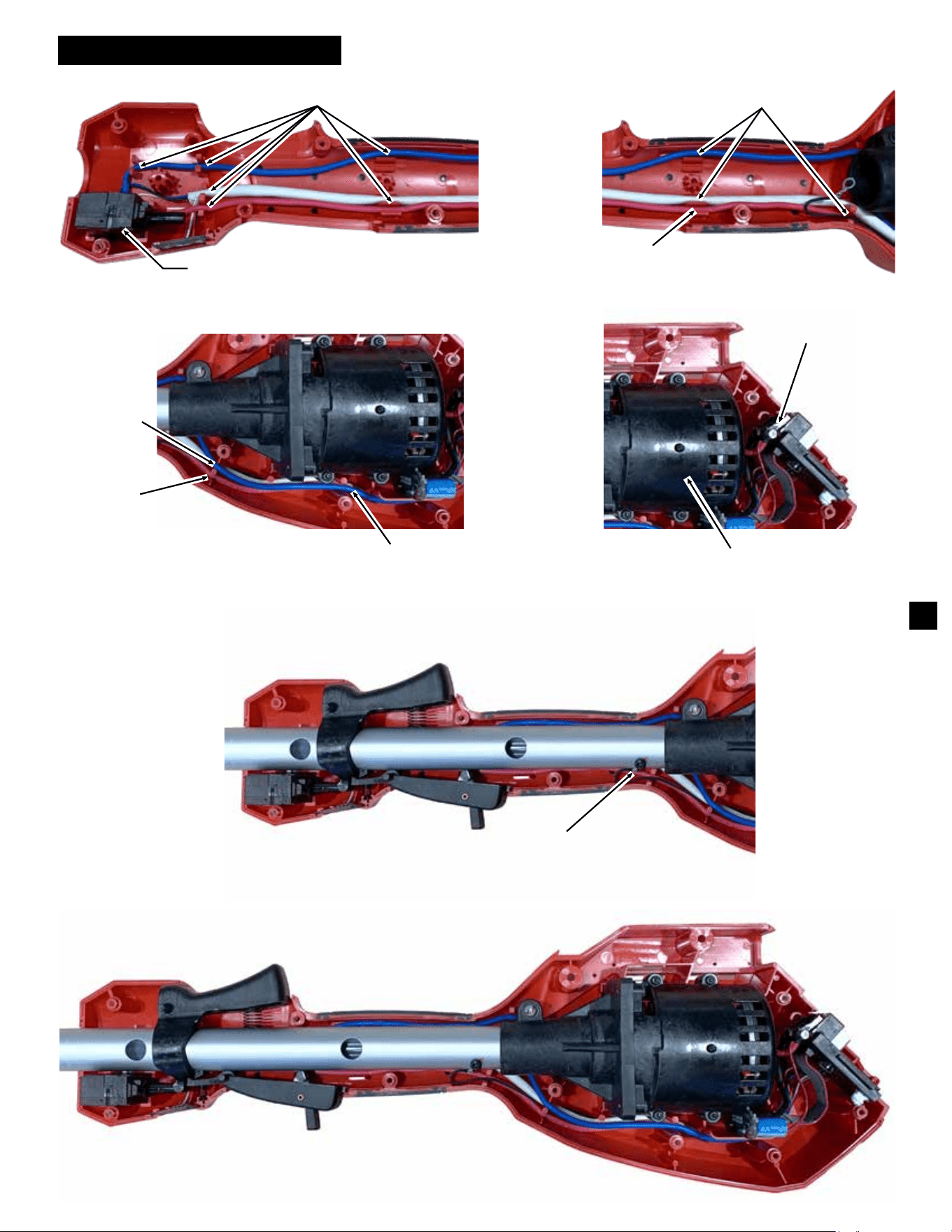
SERVICE WIRING DIAGRAM
Wire Traps and Channels
Wire Traps and Channels
Make sure red wire is
placed completely in
wire trap.
Tighten screw with
HV wire to Drive
Shaft Assembly
Switch Assembly
Motor Insulator/ Encasing
Rotor and Stator
Red wire is connected
to top terminal.
Place wires in this order
from top to bottom:
1. Blue wire
2. Red Wire
3. White wire
4. Black wire
Place wires in
this order
from
top to bottom:
1. Blue wire
2. White wire
3. Black wire
Red wire
15