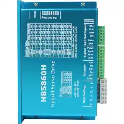
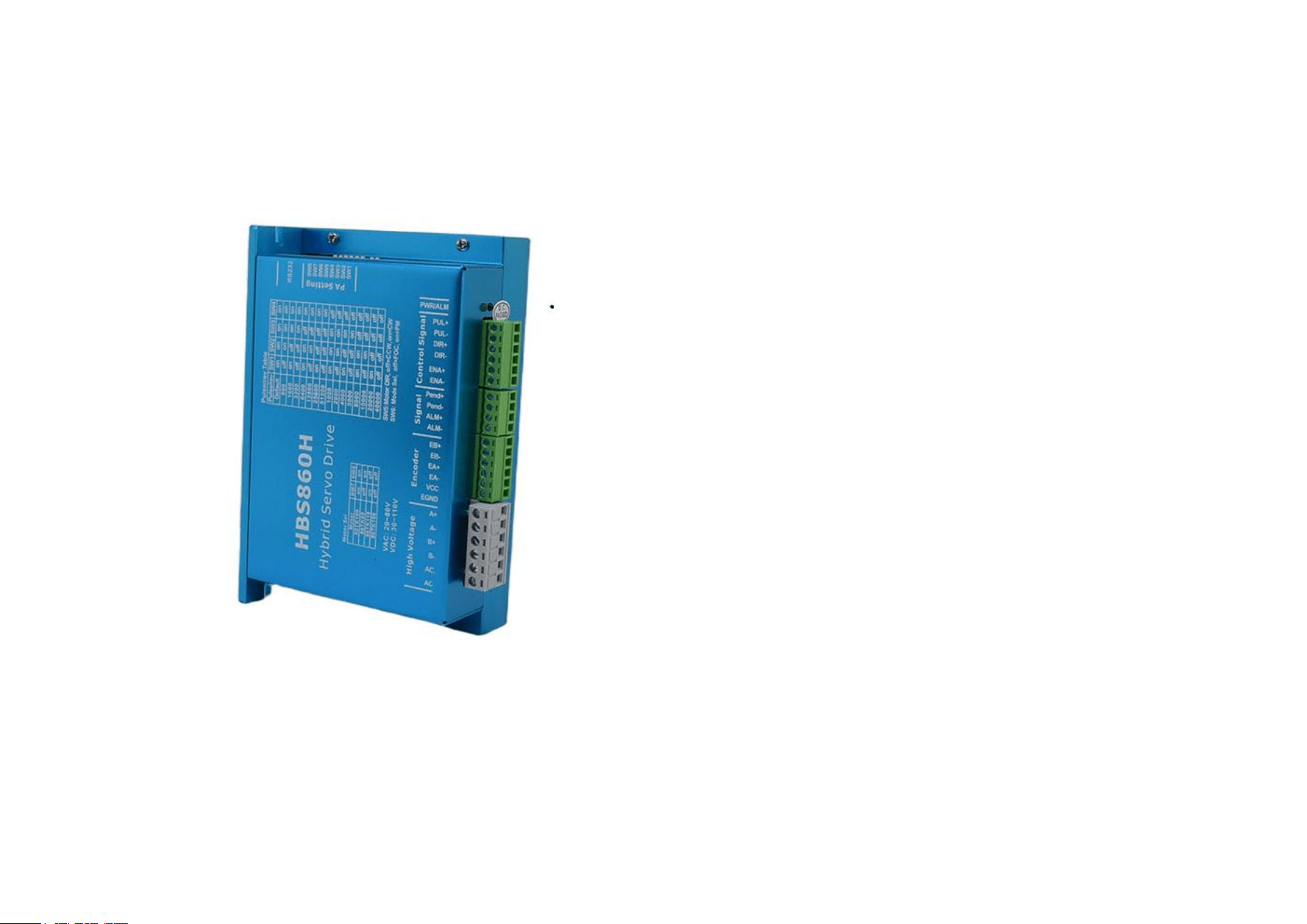
Manual for Digital Closed-Loop Stepper Driver V1.0
[ Please read the manual carefully before us e to avoid dam age to the driver]
CONTENTS
PREFACE.......................................................................................................................1
SAFETY PRECAUTIONS............................................................................................ 1
1.
PRODUCT INTRODUCTION..................................................................................4
1.1.
OUTLINE 4
1.2.
FEATURES.....................................................................................................................................4
1.3.
APPLICATION............................................................................................................................. 5
2.
ELECTRICAL, ENVIRONMENTAL INDEX.........................................................5
2.1.
ELECTRICAL INDEX................................................................................................................. 5
2.2.
ENVIRONMENTAL INDEX....................................................................................................... 5
2.3.
INSTALLATION DIAGRAM.......................................................................................................6
2.4.
DRIVER INSTALLATION........................................................................................................... 7
3.
DRIVER INTERFACE AND WIRING....................................................................7
3.1.
INTERFACE DEFINITION......................................................................................................... 7
3.2.
CONTROL SIGNAL WIRING.................................................................................................... 9
3.3.
OUTPUT SIGNAL WIRING.....................................................................................................11
3.4.
CONTROL SIGNAL MODE SETTING................................................................................... 11
3.5.
ENCODER WIRING................................................................................................................. 11
3.6.
SERIAL WIRING...................................................................................................................... 12
3.7.
STATUS INDICATOR LED....................................................................................12
4.
DIP SWITCH SETTING......................................................................................... 13
5.
TYPICAL APPLICATION WIRING DIAGRAM.................................................. 15
5.1.
CLOSED LOOP STEPPER MOTOR ENCODER LINE COLORAND DEFINITION.........
16
5.2.
CLOSED LOOP STEPPER MOTOR LINE COLOR AND DEFINITION............................ 16
HBS860H digital closed-loop stepper driver manual
V1.0
HBS860H digital closed-loop stepper driver manual
V1.0
!未定义的书签,I
1
2
Web: www.zlingkj.com
1 2
PREFACE
Thanks for choosing the HBS860H digital closed-loop stepper driver.
This manual describes the installation, debugging, maintenance, operation and
other aspects of the HBS860H digital closed-loop stepper driver. Please read this
manual carefully before use, and be familiar with the safety precautions. This
manual may will be revised timely when product is improved, specifications and
version are changed or for some other reasons, which will not be notified again.
Any questions when using our products, please read the relevant manual or call
our technical service department, we will meet your requirements in the shortest
possible time.
Marks and warning signal:
Danger: Indicates that this operation error may endanger personal
safety!
Attention: Indicates that this operation error may result in
equipment damage!
SAFETY PRECAUTIONS
Installed on a non-flammable metal frame, prevent the intrusion of dust,
corrosive gases, conductive objects, liquids and flammable materials, and maintain
good heat dissipation conditions;
During installation, be sure to tighten the mounting screws of the driver.
The stepper driver and stepper motor should be protected from vibration and shock.
Wiring
Please perform the wiring work by professional electrical engineer;
Before wiring, please confirm that the input power is off. Wiring and
inspection must be performed after the power is turned off and the driver indicator is
off to prevent electric shock;
When plugging and unplugging the driver terminals, make sure that the
driver indicator is off before proceeding;
The grounding terminal PE shall be reliably grounded through the left
screw of the driver;
Please set the emergent stop circuit outside the controller;
Do not connect the power input cable to the terminal of A+、A-、B+、B-;
Please tighten the output terminal with a suitable torque.
Open Box and Check
Electrify
Please confirm whether the main circuit input power is consistent with the
Controllers missing parts or damaged, do not install them;
The stepper driver must be used with a matching stepper motor.
Installation
rated working voltage of the driver;
Do not test the driver for high voltage and insulation resistance at will;
Do not connect the electromagnetic contactor or electromagnetic switch to
the output circuit.
HBS860H digital closed-loop stepper driver manual
V1.0
HBS860H digital closed-loop stepper driver manual
V1.0
!未定义的书签,II
5
6
Web: www.zlingkj.com
Operation
Do not directly touch the output terminals after the driver is powered on;
When the system is running, the driver and motor may have a high
temperature rise, do not touch it
Please confirm the input and output signals to ensure safe operation;
The alarm can be reset only after the operation signal is cut off. Alarm
resetting in the running signal state will cause the driver to restart suddenly;
Do not change the parameter settings of the driver at will. The parameter
modification needs to be performed under standby condition.
Maintenance and Inspection
Do not touch the controller terminals directly, and some have high voltage,
very dangerous;
Before powering up,be sure to install the cover; when removing the cover,
be sure to cut off the power supply first;
Before wiring, please confirm whether the input power is off;
After cutting off the main circuit input power and confirming the driver
indicator light has completely extinguished, it can be inspected and maintained;
Do the inspection and maintenance by professional electrical engineer;
Do not do wiring, disassembling or other operation on the terminals
during power on.
There is an integrated circuit on the main control board of the driver.
Please pay full attention when checking to avoid damage caused by static
induction.
1. PRODUCT INTRODUCTION
1.1. Outline
The 2S86 stepper driver is a high performance digital closed loop two phase
hybrid motor driver. This series of stepper drivers adopt the latest 32-bit motor
control dedicated DSP chip, and uses advanced digital filter control technology,
resonant vibration suppression technology and precision current control
technology to achieve accurate and smooth operation. This stepper driver series are
featured with high torque output, low noise, low vibration and low heat, making it
ideal for electronic processing equipment, laser processing, medical and small CNC
equipment.
1.2. Features
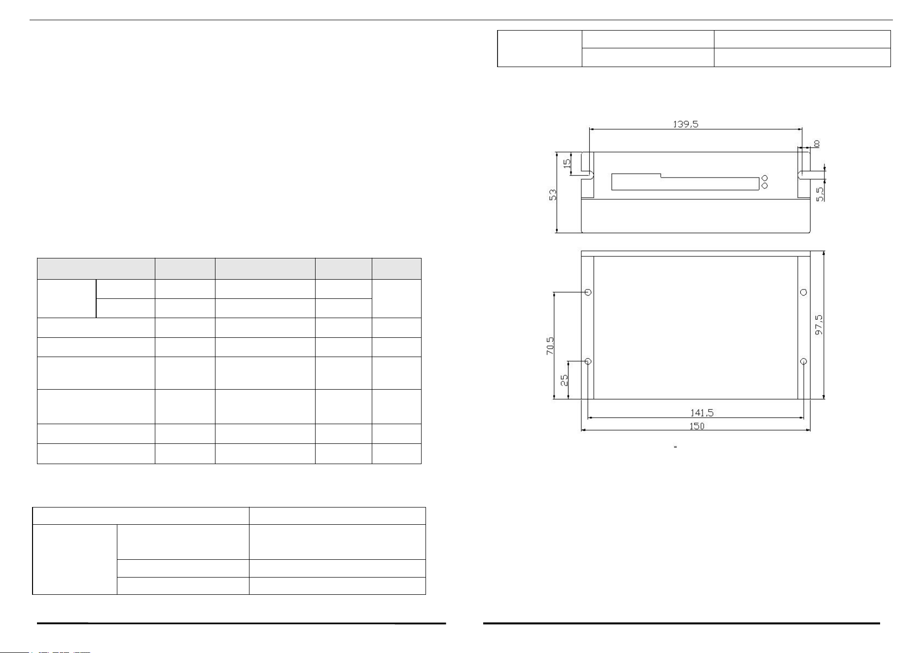
Low vibration and noise;
Max. 512 micro-step subdivision, min. unit 1;
Matching motor: 86mm series and below;
Input voltage: 30~110VDC, 24-80VAC;
Output current: 8A(Peak);
3 optically isolated differential signal inputs: 5~24VDC;
4 DIP switch selection, 16-segment subdivision;
Support single and double pulse
With over-voltage, over-current, out of tolerance protect function etc.;
HBS860H digital closed-loop stepper driver manual
V1.0
HBS860H digital closed-loop stepper driver manual
V1.0
!未定义的书签,III
5
6
Web: www.zlingkj.com
1.3. Application
Suitable for all kinds of small automation equipment and instruments, such as:
pneumatic marking machine, labeling machine, cutting machine, laser marking
machine, plotter, small engraving machine, CNC machine tool, pick and place
device. It is particularly effective in applications where users expect low noise, low
vibration, high stationarity and high precision.
2. ELECTRICAL, ENVIRONMENTAL INDEX
2.1. Electrical Index
Driver Parameter
Min.
Standard
Max.
Unit
Input
voltage
DC
30
36/48
110
V
AC
24
80
Output current peak
1
-
8
A
Step signal frequency
0
-
200k
Hz
Control signal input
current
7
10
16
mA
Over-voltage
protection
-
120
-
VDC
Input signal voltage
5
-
24
VDC
Insulation resistance
100
MΩ
2.2. Environmental Index
2.3. Installation Diagram
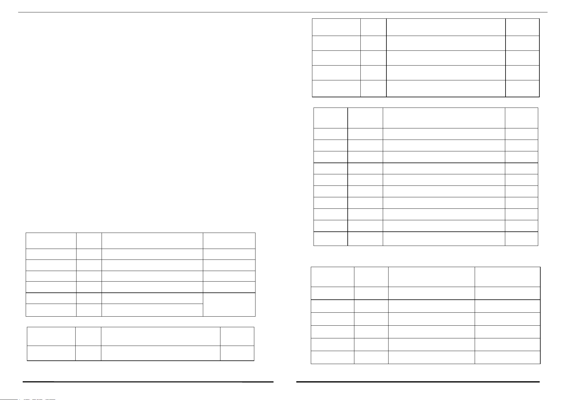
Fig.1 Installation dimension diagram(unit: mm)
Cooling Type
Natural cooling or forced cooling
Service
environment
Application occasion
Avoid dust, oil mist and
corrosive gases
Service temperature
0~50℃
Max. ambient humidity
90% RH (no condensation))
Storage temperature
-10~70℃
Vibration
10~55Hz/0.15mm
HBS860H digital closed-loop stepper driver manual
V1.0
HBS860H digital closed-loop stepper driver manual
V1.0
!未定义的书签,IV
7
8
Web: www.zlingkj.com
2.4. Driver Installation
Users can install with the wide or narrow side of the driver's cooling base. If
install with a wide side, use M3 screw to install through the holes in the four corners.
If install with narrow side, use M3 screws to install through the holes on both sides.
For good heat dissipation, the narrow side mounting is recommended.
The driver power device will generate heat. If continuous operation is under
high input voltage and high power conditions, the effective heat dissipation area or
forced cooling should be expanded. Do not use in places where air is not circulating
or where the ambient temperature exceeds 60℃; do not install the driver in a place
that is wet or has metal shavings.
3. DRIVER INTERFACE AND WIRING
3.1. Interface Definition
3.1.1
Motor and power input port
Terminal NO.
Mark
Name
Remark
1
A+
Phase A motor winding+
2
A-
Phase A motor winding-
3
B+
Phase B motor winding+
4
B-
Phase B motor winding-
5
AC1
Input power 1
+30V~ +100VDC
24V-80VAC
6
AC2
Input power 2
3.1.2
Encoder signal input port
2
EB-
Motor encoder B phase negative input
3
EA+
Motor encoder A phase positive input
4
EA-
Motor encoder A phase negative input
5
VCC
Encoder power supply
+5V
6
GND
Encoder power ground
0V
3.1.3
Control Signal Terminal
Terminal
NO.
Mark
Name
Remark
1
PUL+
Pulse positive input
2
PUL-
Pulse negative input
3
DIR+
Direction positive input
4
DIR-
Direction negative input
5
ENA+
Enable positive input
6
ENA-
Enable negative input
7
Pend+
In-position signal positive output
8
Pend-
In-position signal negative output
9
ALM+
Alarm signal positive output
10
ALM-
Alarm signal negative output
3.1.4
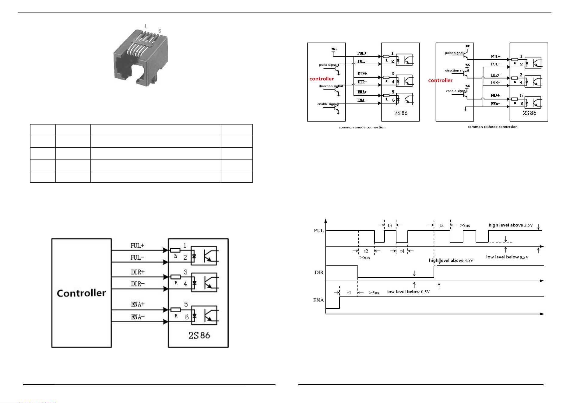
RS232 communication interface
RS232 interface pin alignment definition as below
Terminal NO.
Mark
Name
Remark
1
EB+
Motor encoder B phase positive input
Terminal NO.
Mark
Name
Remark
1
NC
2
RxD
RS232 receiver
3
GND
Power ground
4
NC
5
TxD
RS232 sender
6
3.3V
Power supply positive end
Internal power supply
HBS860H digital closed-loop stepper driver manual
V1.0
HBS860H digital closed-loop stepper driver manual
V1.0
!未定义的书签,V
9
10
Web: www.zlingkj.com
Fig.2 RS232 interface pin alignment definition
3.1.5
Encoder signal output port
Termi
Mark
Name
Remark
1
EB
-
Motor encoder B phase negative output
2
EB
+
Motor encoder B phase positive input
3
EA-
Motor encoder A phase negative input
4
EA+
Motor encoder A phase positive output
3.2. Control Signal Wiring
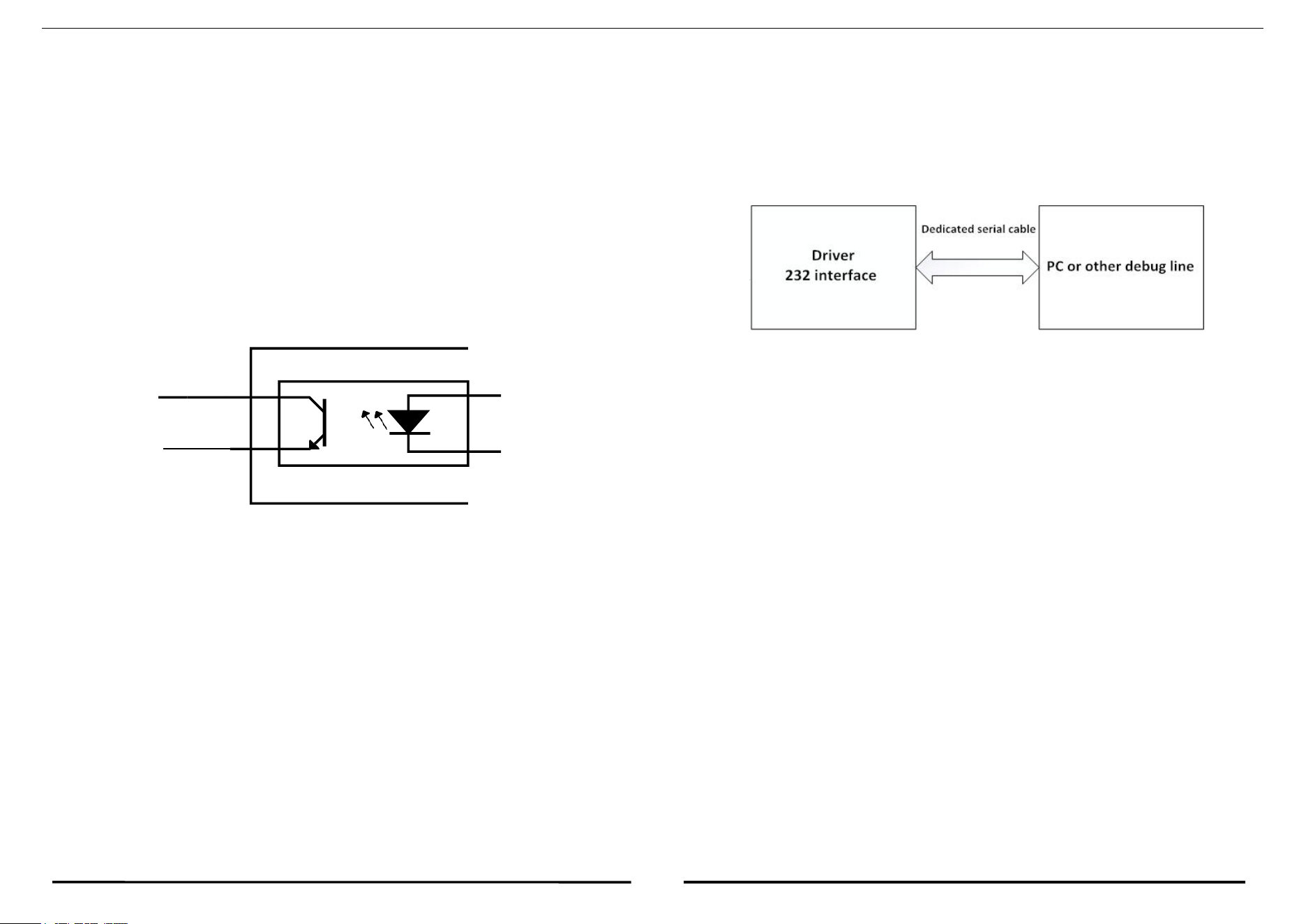
Control signal differential mode input, control signal interface wiring diagram,
as shown below:
as shown below:
Fig.3 Input interface circuit
Note: The control signal level is common for 5-24V.
Control signal timing diagram
In order to avoid some wrong actions and deviations, PUL, DIR and ENA
should meet certain requirements, as shown below:
Fig.4 Control signal timing diagram
Note:
Control signal single-ended mode input, control signal interface wiring diagram
1)
t1: ENA (enable signal) should be confirmed to be high at least 5μs ahead ofDIR.
In general, it is recommended that ENA+ and ENA- is hanging.
HBS860H digital closed-loop stepper driver manual
V1.0
HBS860H digital closed-loop stepper driver manual
V1.0
!未定义的书签,VI
13
14
Web: www.zlingkj.com
ALM+
ALM-
2)
t2: DIR is confirmed for its state to be high or low at least 5μs ahead of PUL
falling edge.
3)
t3: The pulse width is at least not less than 2.5μs.
4)
t4: The low level width is not less than 2.5μs.
3.3. Output Signal Wiring
Signal output wiring, such as alarm signal output ALM, photoelectric isolation OC
output, maximum withstand voltage 30VDC, maximum saturation current 50mA.
Fig.4 Output Signal Wiring
3.4. Control Signal Mode Setting
Pulse trigger edge and single and double pulse selection: The pulse rising edge
or falling edge trigger is effective by dialing setting;It is also possible to set the
single pulse mode or the double pulse mode.
3.5. Encoder Wiring
Directly powered by HBS860H , GND is connected to the encoder ground,
VCC is connected to the encoder power supply +, encoder A+, A-, B+, B- signals
are correspondingly connected to the drive EA+, EA-, EB+, EB- port.
3.6. Serial Wiring
Fig.5 Serial wiring diagram
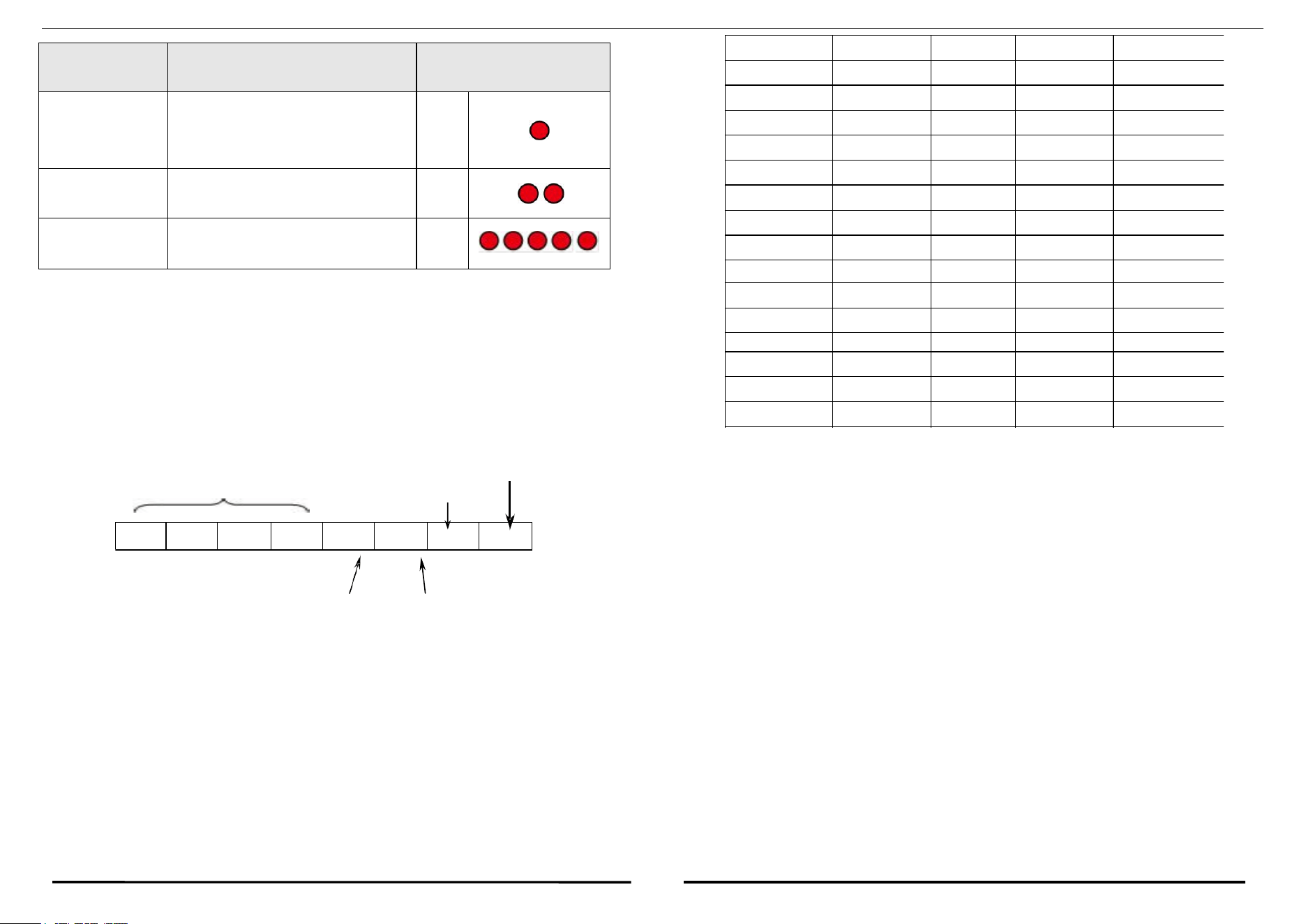
3.7. Status Indicator LED
The green LED is the power indicator, which is always on when the driver is
powered up; it is off when the driver is powered off. The red LED is the fault
indicator. When the driver fails, it will stop and prompt the corresponding fault code.
The fault can be cleared when the user needs to power off and restart the power. The
status indicator LED represents different operation and fault information, as shown
in the following table:
HBS860H digital closed-loop stepper driver manual
V1.0
HBS860H digital closed-loop stepper driver manual
V1.0
!未定义的书签,VII
13
14
Web: www.zlingkj.com
Status
Condition
Status indicator LED
description
over-current
The phase current through the motor
exceeds the rated current or the
phase-to-phase short circuit
1 red
over-voltage
Power supply voltage exceeds
maximum rated voltage
2 red
out-of-tolerance
Position out of tolerance
5 red
4. DIP SWITCH SETTING
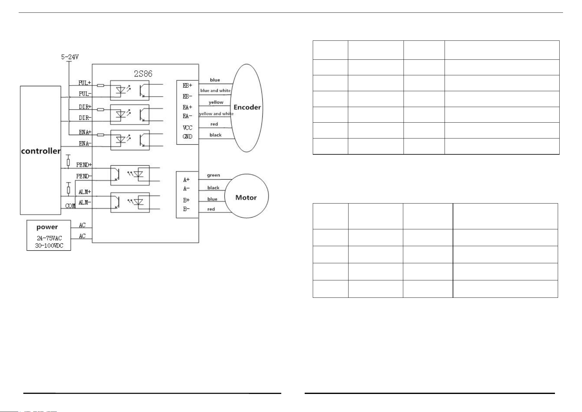
2S86 driver use an eight-digit dial switch, set the subdivision accuracy, control
signal mode, effective edge and motor rotate direction. The detailed description is as
follows:
SW5: Motor rotate direction setting. When SW5=off, the motor rotates
Subdivision accuracy setting
Motor selection Pulse mode
selection
counterclockwise (CWW); SW5=on, rotates clockwise (CW).
SW6: Motor algorithm selection.
Motor rotate direction selection Motor algorithm
Subdivision settings. The subdivision parameters can be customized according to
customer requirements. The range is 400~51200 Step/Rev.
SW7 SW8: Set the Motor type.
Step/Rev
SW1
SW2
SW3
SW4
400 (Default)
ON
ON
ON
ON
800
OFF
ON
ON
ON
1600
ON
OFF
ON
ON
3200
OFF
OFF
ON
ON
6400
ON
ON
OFF
ON
12800
OFF
ON
OFF
ON
25600
ON
OFF
OFF
ON
51200
OFF
OFF
OFF
ON
1000
ON
ON
ON
OFF
2000
OFF
ON
ON
OFF
4000
ON
OFF
ON
OFF
5000
OFF
OFF
ON
OFF
8000
ON
ON
OFF
OFF
10000
OFF
ON
OFF
OFF
20000
ON
OFF
OFF
OFF
40000
OFF
OFF
OFF
OFF
SW1
SW2
SW3
SW4
SW5
SW6
SW7
SW8
HBS860H digital closed-loop stepper driver manual
V1.0
HBS860H digital closed-loop stepper driver manual
V1.0
!未定义的书签,VIII
15
16
5. TYPICAL APPLICATION WIRINGDIAGRAM
Fig.6 Typical Application Wiring Diagram
5.1. Closed Loop Stepper Motor Encoder Line Color and Definition
Pin
Encoder line
color
Signal
Description
1
blue
EB+
Encoder B channel positive output
2
blue and white
EB-
Encoder B channel negative output
3
yellow
EA+
Encoder A channel positive output
4
Yellow and white
EA-
Encoder A channel negative output
5
red
VCC
Encoder +5V power input
6
black
GND
Encoder GND input
5.2. Closed Loop Stepper Motor Line Color and Definition
Pin
86 motor color
Signal
Description
1
Red
A+
Phase A motor winding+
2
Blue
A-
Phase A motor winding-
3
black
B+
Phase B motor winding+
4
green
B-
Phase B motor winding-