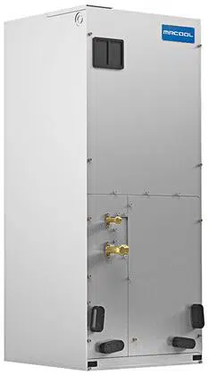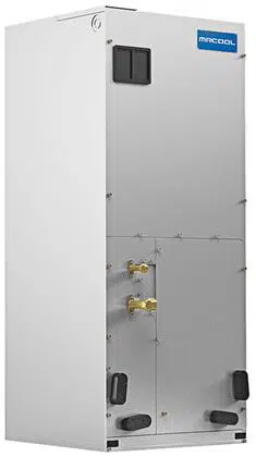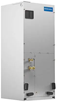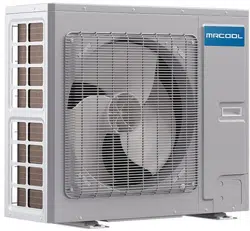
UNIVERSAL
®
Series
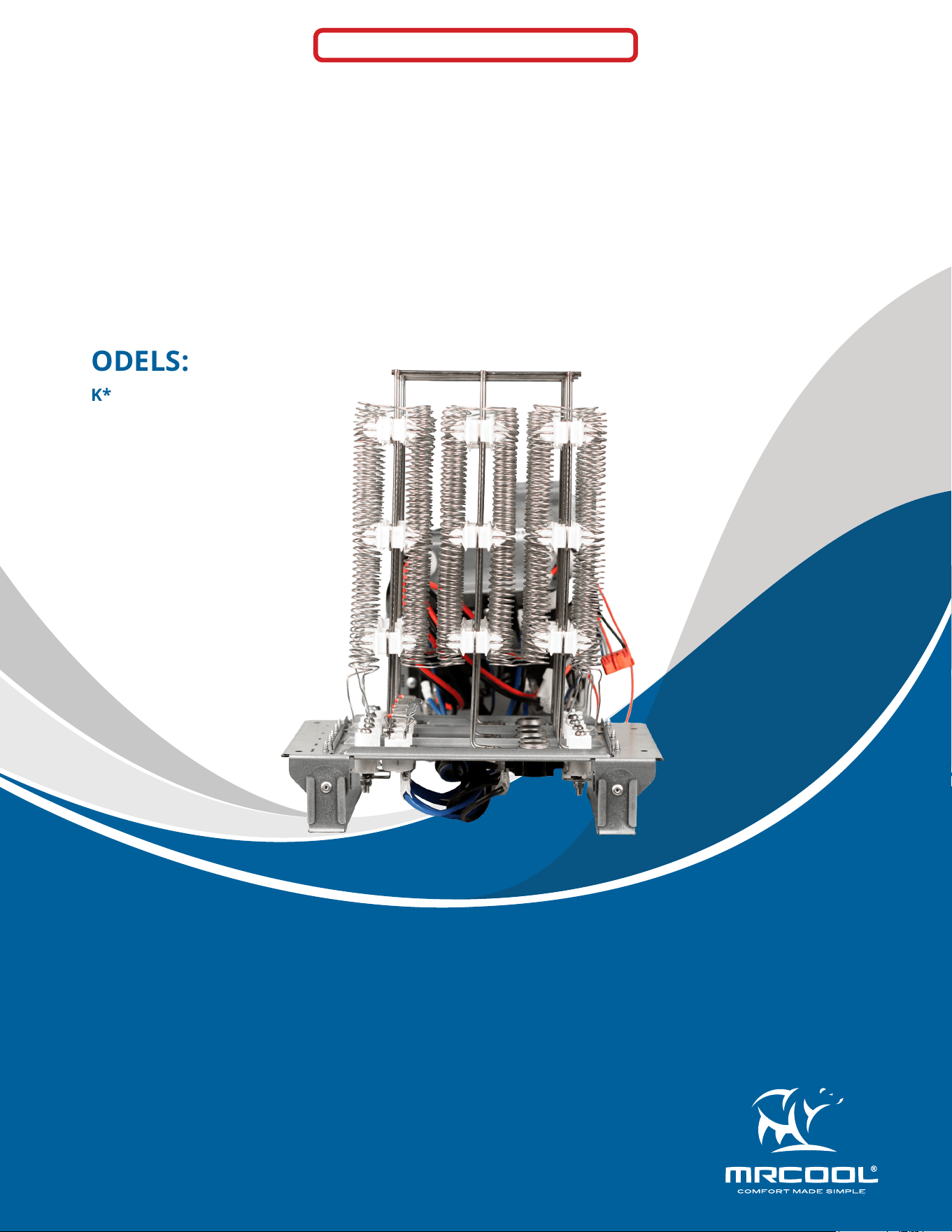
Heat Kit
Installation &
Owner’s Manual
MODELS:
Read this manual carefully before installation and keep it where
the operator can easily nd it for future reference.
Due to updates and constantly improving performance, the
information and instructions within this manual are subject to
change without notice.
Version Date: May 30, 2025
Please visit www.mrcool.com/documentation
to ensure you have the latest version of this manual.
UHK*
This product utilizes R-454B refrigerant
mrcool.com1
CONTENTS
SAFETY ..............................................................................................................................................1
INSTALLATION .................................................................................................................................2
ELECTRICAL SPECIFICATIONS .........................................................................................................6
1
2
3
Incorrect usage may cause serious damage or injury.
The symbols below are used throughout this manual to indicate instructions that should be followed closely
or actions that should be avoided to prevent death, injury, and/or property damage.
Safety Precautions
CAUTION
Indicates a medium level of risk which, if not avoided, may
result in death or serious injury.
Indicates a low degree of risk which, if not avoided, may
result in minor or moderate injury.
Indicates important information but not danger.
Read Before Using
WARNING
NOTICE
ELECTRICAL WARNINGS
1. The product must be properly grounded during installation or electrical shock could occur.
2. For all electrical work, follow all local and national wiring standards, regulations, and the installation
manual. Connect cables tightly and clamp them securely to prevent external forces from damaging the
terminal. Improper electrical connections could overheat, causing re and/or electrical shock.
3. All electrical connections must be made according to the Electrical Connection Diagram located on the
panels of the indoor and outdoor units.
4. If connecting power to xed wiring, an all-pole disconnection device must be incorporated in the xed
wiring in accordance with the wiring rules and must meet the following requirements: at least 3 mm of
clearances in all poles, a leakage current that may exceed 10 mA, and a residual current device (RCD)
having a rated residual operating current not exceeding 30 mA.
5. All wiring must be properly arranged to ensure that the control board cover can close properly. If the
control board cover is not properly closed, it can lead to corrosion and cause the connection points on the
terminal to heat up, catch re, or cause electrical shock.
WARNING
1. Turn o the device and disconnect the power before performing any installation, cleaning, or repairs.
Failure to do this could result in electrical shock.
2. This appliance is not intended for use by persons (including children) with reduced physical, sensory,
or mental capabilities, or lack of experience or knowledge, unless they have been given supervision or
instruction concerning use of the appliance by a person responsible for their safety. Children should be
supervised to ensure that they do not play with the appliance.
SAFETY
1
mrcool.com 2 2
INSTALLATION
2
WARNINGS FOR PRODUCT INSTALLATION
INSTALLATION MUST BE PERFORMED BY AN AUTHORIZED DEALER OR SPECIALIST. DEFECTIVE
INSTALLATION CAN CAUSE WATER LEAKAGE, ELECTRICAL SHOCK, OR FIRE.
****ELECTRICAL WORK MUST BE COMPLETED BY A QUALIFIED ELECTRICAL TECHNICIAN****
DO NOT install the unit in a location that may be exposed to combustible gas leaks. If
combustiblegasaccumulatesaroundtheunit,itcouldcausere.
DO NOT turn on the power until the installation and all work has been completed.
DO NOT install a unit equipped with an auxiliary electric heater within 3 ft (1 m) of any
combustible materials.
1. Installation must be performed according to the installation instructions. Improper installation could cause
water leakage, electrical shock, re, and could void the warranty. Contact an authorized service technician
for repair or maintenance of this unit. This appliance must be installed in accordance with national wiring
regulations.
2. Only use the included accessories, parts, and specied parts for installation. Using non-standard parts can
cause water leakage, electrical shock, re, and/or failure of the unit.
3. When moving or relocating the air conditioner, consult experienced service technicians for disconnection
and re-installation of the unit.
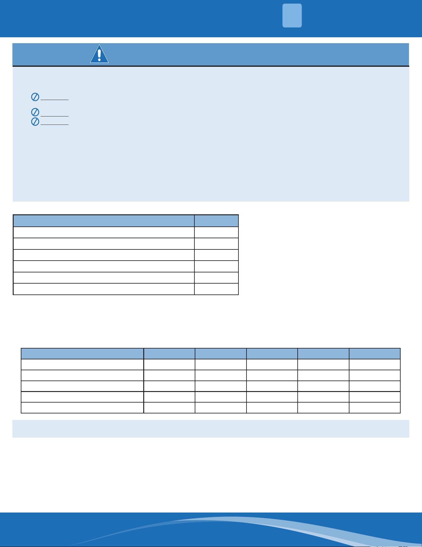
Model Size Selection
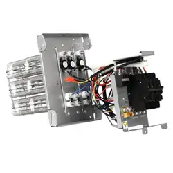
For installations requiring supplemental heating, the optional Electric Auxiliary Heat Module is available in sizes
from 5kW to 20kW to accommodate appropriate sizing given the specic heat load and electrical requirements
of each installation. Refer to the table below for selection of available sizes of each model, being sure to avoid
improper matching.
Accessories
Name Quantity
Manual 1
Foam Gasket 2
Screw Pack 1
Silicone Breaker Cover 1 or 2
Electric Auxiliary Heating Wiring Diagram 1
Circuit Breaker Label 1
Only use compatible modules certied for use with the model. Refer to the Electric Auxiliary Heat Model specication for
additional details to ensure proper selection and installation.
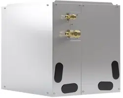
Model (Btu/h) UHK05 UHK08 UHK10 UHK15 UHK20
UHP18024-O Y Y Y Y -
UHP18030-O Y Y Y Y -
UHP18036-O Y Y Y Y Y
UHP18048-O - Y Y Y Y
UHP18060-O - - Y Y Y
mrcool.com3
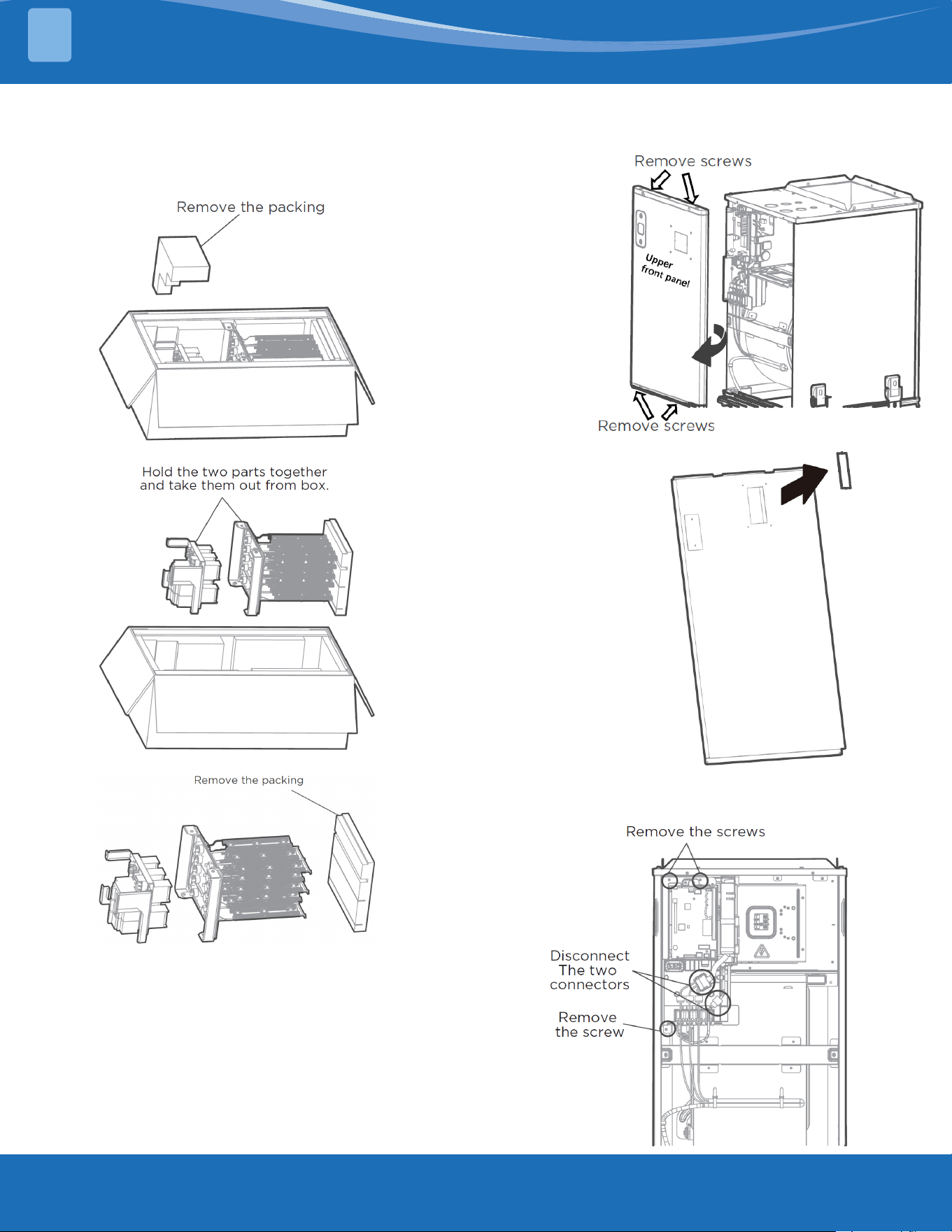
Step 3:
INSTALLATION
2
Installation Preparation
Before installation, conrm the electric auxiliary heat
module and supplied accessories are present and
free of damage. Do not attempt to install if damage is
present.
Electric Auxiliary Heat Module Installation and
Wiring Operation
Step 1:
Open the
upper cover.
Step 2:
Use tools to remove
the knock-out holes
of the upper cover.
mrcool.com 4
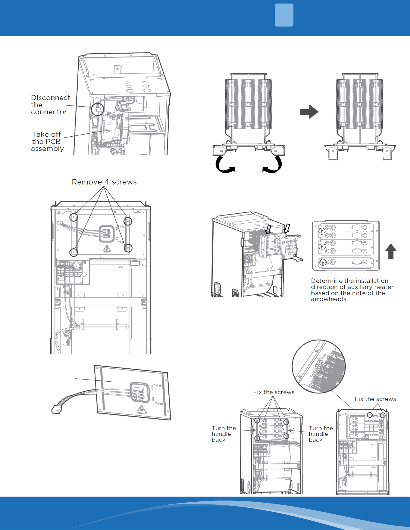
Step 4:
Step 5:
Step 6:
Turn the handles of the heater in the direction
specied in the gure below.
Step 7:
Hold the two handles and push the heat kit
horizontally into the indoor unit.
Step 8:
Turn the handles back and x with screws.
INSTALLATION
2
Remove the cover
and keep the wiring
until installation is
complete.
mrcool.com5
INSTALLATION
2
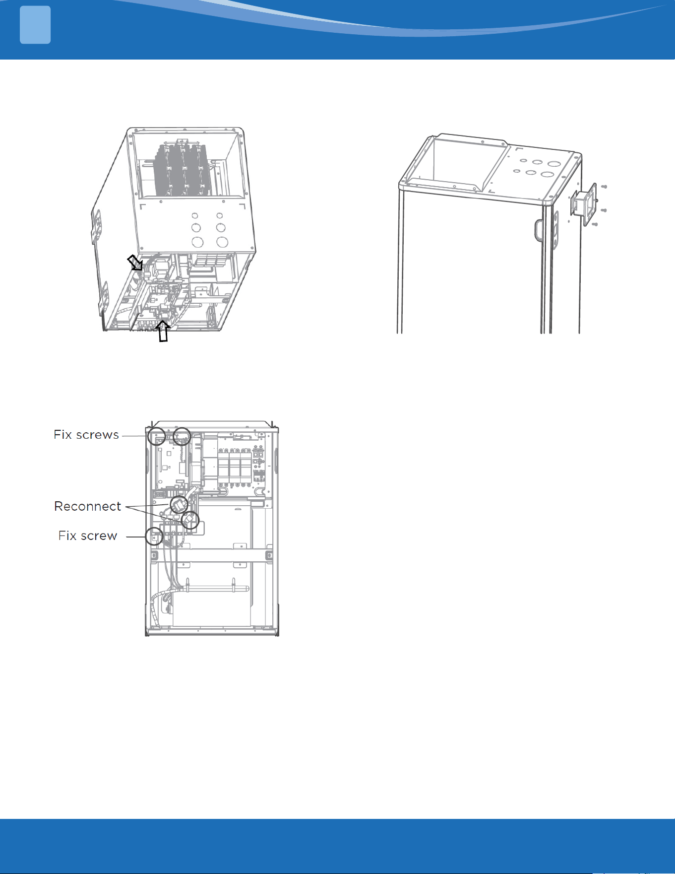
Step 9:
Attach the connector from the heat kit onto the board
assembly according to the wiring diagram.
Step 10:
Install the PCB back and reconnect the connector. Fix
3 screws.
Step 11:
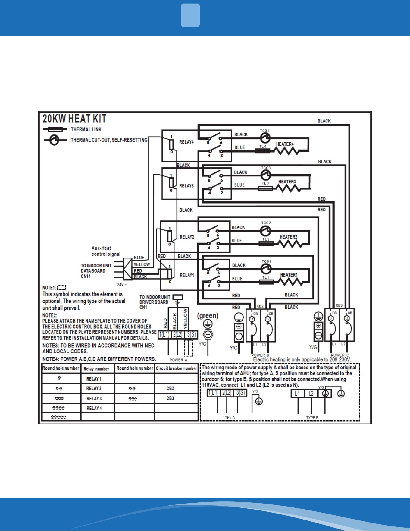
Wire according to the wiring diagram. Apply the wiring
diagram on the inside cover after wiring is completed
for future reference and maintenance.
Step 12:
Install the front panel and the silicone breaker cover
with screws.
Step 13:
After installing the heat kit, apply the circuit breaker
label near the silicone breaker cover that was just
applied.
mrcool.com 6
NOTICE
• The electric auxiliary heating wiring diagram is packed with the accessories.
• If the branch circuit wire length exceeds 100ft, consult NEC 210-19a to determine maximum wire length.
• Use 2% voltage drop.
Aftertheelectricheatingwiringisconnected,pleaseconrmthefollowingbeforepoweringon:
• Check and ensure a secure connection of all wiring.
• Ensure that wire size is properly selected per NEC or local codes.
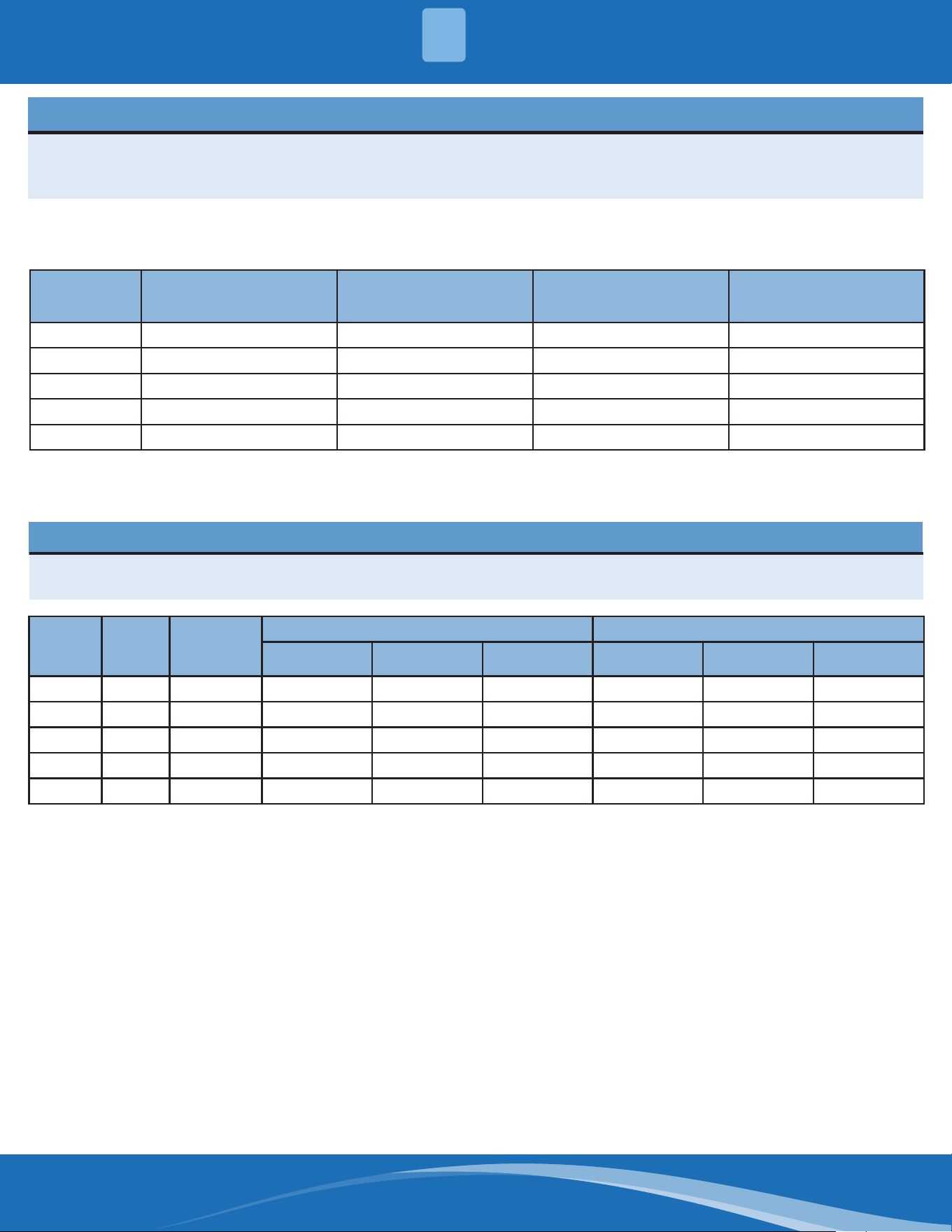
Model
Number of Circuit
Breakers
Number of Relays
Number of Power Cord
Groups
Number of Power Cord
Grounding Screws
5kW 1 1 2 2
8kW 1 2 2 2
10kW 1 2 2 2
15kW 2 3 3 3
20kW 2 4 3 3
Use copper wire only to connect unit. If other than uncoated (non-plated) 75°C copper wire (solid wire for 10
AWG and smaller, stranded wire for larger than 10 AWG) is used, consult applicable tables of the National
Electric Code (ANSI/NFPA 70).
NOTICE
The specication may be dierent between dierent models. Refer to the indoor unit’s nameplate. Choose the
cable type according to the local electrical codes and regulations.
Heater
Model
Heater
kW
Internal
Circuit
Protection
Circuit 1 (208/230V) Circuit 2 (208/230V)
Heater Amps MCA (1) MOP (2) Heater Amps MCA (1) MOP (2)
UHK05 5 Ckt Bkr 18.0/20.0 23.0/27.0 25.0/30.0 / / /
UHK08 8 Ckt Bkr 28.8/32.0 37.0/42.0 40.0/45.0 / / /
UHK10 10 Ckt Bkr 36.0/40.0 46.0/53.0 50.0/60.0 / / /
UHK15 15 Ckt Bkr 18.0/20.0 23.0/27.0 25.0/30.0 36.0/40.0 46.0/53.0 50.0/60.0
UHK20 20 Ckt Bkr 36.0/40.0 46.0/53.0 50.0/60.0 36.0/40.0 46.0/53.0 50.0/60.0
ELECTRICAL SPECIFICATIONS
3
mrcool.com7
ELECTRICAL SPECIFICATIONS
3
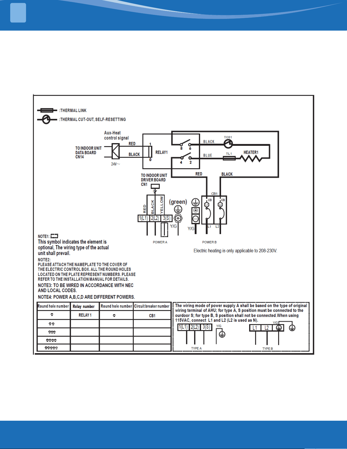
5KW HEAT KIT
mrcool.com 8
ELECTRICAL SPECIFICATIONS
3
mrcool.com9
ELECTRICAL SPECIFICATIONS
3
mrcool.com 10
ELECTRICAL SPECIFICATIONS
3
UNIVERSAL
®
Series
Heat Kit
The design and specications of this product and/or manual are subject to change without prior notice.
Consult with the sales agency or manufacturer for details.