Universal
®
Series
Air Handler (High ESP)
Model - MDUI180**E
Please read this manual carefully before installation and keep it for future reference.
Copyright © 2021 MRCOOL
®
, LLC
Thank you for choosing MRCOOL
®
. Please read this manual carefully before installation and keep it for future reference.
Owner’s Manual
Due to updates and constantly improving performance, the information and instructions within this
manual are subject to change without notice. Please visit www.mrcool.com/documentation to
ensure you have the latest version of this manual.
Version Date: 10-25-21
*Pat. https://mrcool.com/mrcool-patents/
Contents
Page 1 mrcool.com
EU Disposal Guidelines .............. 34
6
Post Installation Checks ........... 28
3
Troubleshooting ......................... 30
4
Maintenance and Care
..............
33
5
Unit Installation ........................... 9
1. Pre-Installation Instructions ........................... 9
3. Conventional Line Set Installation ................ 11
4. No-Vac
®
Quick Connect
®
* Installation ........ 13
5. Bending the Line Set ....................................... 14
6. Condensate Removal ..................................... 14
2. Installation Location ........................................ 10
8. Electric Heat Kit Installation ............................ 15
9. Air Handler Field Conversion .......................... 17
11. Electrical Connection ....................................... 22
7. Ductwork ............................................................ 15
2
10. Set Indoor Fan Speed ...................................... 18
1. Introduction ........................................................ 5
2. Accessories ........................................................ 6
4. Main Parts ........................................................... 8
1
Appliance Overview ..................... 5
Safety Precautions ....................... 2
!
3. Unit Dimensions ................................................ 7
1. Test Run ............................................................. 29
Page 2
Safety Precautions
mrcool.com
WARNING
Please read the manual in its entirety before installing, operating or repairing.
DO NOT share the electrical circuit with other appliances. An improper or insufficient
power supply could cause fire and/or electrical shock.
DO NOT let substances or gases enter the unit when connecting refrigerant piping. The
presence of other gases or substances will lower the unit’s capacity, and may cause
abnormally high pressure during the operation cycle. This could cause an explosion and/or
personal injury.
DO NOT connect the ground wire to a gas pipe, water pipe, lightning arrester, or
telephone wire.
DO NOT allow children to play with the air conditioner. Children should be supervised
around the unit at all times.
DO NOT alter the settings of the pressure sensor or other protective devices; if
short-circuited or modified, fire and/or an explosion could occur.
Installation must be performed by an authorized technician. Improper installation could cause
water leakage, electrical shock, and/or fire.
Installation must be performed according to installation instructions. Improper installation may
cause water leakage, electrical shock, or fire.
In North America, installation must be performed in accordance with the requirements of NEC
and CEC (by authorized personnel only.) Contact an authorized service technician for repair or
maintenance of the unit.
Only use the included accessories and specified parts for installation. Using non-standard parts
can cause water leakage, electrical shock, fire, and could cause the unit to fail.
The United States Protection Agency (”EPA”) has issued various regulations regarding the
introduction and disposal of refrigerants introduced into this unit. Failure to follow these
regulations could harm the environment and can lead to a substantial fine. These regulations
may vary due to the passage of laws. A certified technician must perform the installation and
service of this product. Should questions arise, contact your local EPA office.
Read Before Installation
Incorrect installation may cause serious damage or injury.
The seriousness of potential damage or injuries is classified as either a WARNING or CAUTION.
WARNING
CAUTION
This symbol indicates ignoring instructions may cause death or serious injury.
This symbol indicates that ignoring instructions may cause moderate personal
injury, damage to the unit, or other property.
This symbol indicates that you should NEVER perform the indicated action.
1.
2.
3.
4.
!
Safety Precautions
5.
Page 3
Safety Precautions
mrcool.com
Note about Fluorinated Gases:
1.
2.
3.
4.
5.
6.
8.
9.
10.
11.
12.
13.
14.
15.
7.
6.
Install the unit in a firm location that can support the unit’s weight. If the installation location
cannot support the weight, or the installation is performed improperly, the unit could fall and
cause serious personal injury and/or property damage.
For all electrical work, follow all appropriate wiring standards, regulations, and the installation
manual.
You must use an independent circuit to supply power. DO NOT connect other appliances to
the same circuit. Insufficient electrical capacity or defects in electrical work could cause
electrical shock and/or fire.
Connect electrical cables tightly and clamp them securely to prevent external forces from
damaging the terminal. Improper electrical connections could overheat, causing fire and/or
electrical shock.
All wiring must be properly arranged to ensure that the control board cover can close properly.
If the control board cover is not closed properly, it can lead to corrosion and cause the
connection points on the terminal to overheat, which could cause fire and/or electrical shock.
In certain functional environments (such as kitchens and server rooms), the use of specially
designed air-conditioning units is highly recommended. If the power or thermostat wires are
damaged, they must be replaced by an authorized technician in order to avoid a hazard.
This appliance can be used by children aged 8 years and older and persons with reduced
physical, sensory, or mental capabilities or lack of experience and knowledge if they have been
given supervision or instruction concerning use of the appliance and understand the hazards
involved. Children should not play with the appliance. Cleaning and user maintenance should
not be performed by children.
The air conditioner unit can only be cleaned after it has been turned off and disconnected from
its power source, otherwise electric shock could occur.
If installed in a compact space, ensure that there is adequate ventilation in case of leakage.
Concentrations of refrigerant gas could lead to an explosion and other hazards.
The fixed wires connecting to this appliance must be configured with an all-pole disconnect
under voltage class III.
Wear safety glasses, protective clothing, work gloves, and have a fire extinguisher available
during installation.
Always use a quenching cloth for brazing operations.
This air-conditioning unit contains R-410A fluorinated gases.
The refrigerant gas may not have an odor, so this should not be considered as a means of leak
detection.
Installation, service, maintenance, and repair of this unit must be performed by a certified
technician.
Product un-installation and recycling must be performed by a certified technician.
If the system has a leak-detection system installed, it should be checked for leaks at least once
every 12 months.
Keep a record of all leak checks for the lifetime of the unit.
16.
17.
Page 4
Safety Precautions
mrcool.com
1.
2.
DO NOT install the unit within 3 ft (1 m) of combustible materials if the unit is equipped
with an auxiliary electric heater.
DO NOT install the unit in a location where it could be exposed to combustible gases. If
combustible gas accumulates around the unit, it could cause fire.
DO NOT operate your air conditioner in a room where it could be exposed to excessive
amounts of water, such as a bathroom or laundry room. Too much exposure to water
could cause the electrical components to short circuit.
DO NOT put appendages or other objects into the air inlet or return grills.
DO NOT stop the appliance by directly cutting off the power. Turn off the unit first.
DO NOT install the appliance in areas with:
• oil, smoke, or volatile liquid; as plastic parts could deteriorate, adversely affecting the
integrity and functionality of the appliance.
• corrosive gas; as this could corrode copper piping and welds, adversely affecting the
integrity and functionality of the appliance.
DO NOT force-dry the filter using an open flame or a blower, as these could damage it.
This appliance must be properly grounded during installation, or electrical shock could occur.
Install drainage piping according to the instructions in this manual. Improper drainage could
cause water damage to your home and property.
This appliance must be stored in a well ventilated area that is equal in size to the area specified
for the operation of the unit.
Use proper measures to protect the unit from rodents and other small animals that could
damage the electrical components of the unit, which could cause it to malfunction.
If wired control (i.e. a wall-mount thermostat) is to be used, it should be connected before
powering up the unit, otherwise it may not function properly.
Only use a soft dry cloth or a slightly wet cloth with neutral detergent to clean the casing of this
appliance.
If the unit has been disconnected from its power source for an extended period of time, before
operating the unit, connect it to its power source for 8 hours. If it is to be deactivated for a
short time, for example, one night, do not cut off the power (this is to protect the compressor).
1.
2.
3.
4.
5.
6.
7.

Page 5
Safety Precautions
mrcool.com
To Our Customers;
Thank you for choosing a MRCOOL
®
home HVAC product. Please read this manual carefully before
installation and operation of the Universal™ Series High-ESP Air Handler to ensure correct use and handling. In
addition to the safety precautions in the previous section, please adhere to the following guidelines and note
our exceptions to liability.
This appliance can be used by children aged 8 years and older and persons with reduced physical, sensory
or mental capabilities or lack of experience and knowledge if they have been given supervision or
instruction concerning use of the appliance in a safe way and understand the hazards involved. Children
should not play with the appliance. Cleaning and user maintenance should not be performed by children.
To ensure product reliability, the unit may consume power under stand-by status to maintain normal
communication, and for preheating refrigerant and lubricant. If the unit will not be used for an extended
period, disconnect the power supply. Reconnect the power supply and preheat the unit prior to use.
Ensure you have selected the proper model for the operating environment. Improper selection may impact
operating performance.
This product has undergone strict inspection and operational testing before leaving the factory. In order to
avoid damage due to improper disassembly, which may impact the normal operation, please do not
disassemble the unit without proper training and equipment.
For technical assistance, please contact MRCOOL
®
technical support at (270) 366-0457.
If the product is malfunctioning and/or is inoperable, please contact MRCOOL
®
technical support at the
aforementioned number, as soon as possible and provide the following information:
a. Product Nameplate Contents (model number, cooling / heating capacity, product serial number,
factory date)
b. Nature of Malfunction (specify the circumstances before and after the error occurred)
All illustrations and information in the instruction manual are for reference only. In order to improve the
product , we will continuously assess and innovate. We retain the right to make necessary revisions to the
product from time to time. We reserve the right to revise the contents of this manual without notice.
If the supply cord is damaged, it must be replaced by MRCOOL
®
, a professional service agent, or a similarly
qualified person in order to avoid damage to the product.
MRCOOL
®
, LLC assumes no responsibility for personal injury, property loss or equipment damage caused
by improper installation, commissioning, unnecessary maintenance, or failure to follow relevant federal and
state regulations, industrial standards, and the requirements of this instruction manual.
MRCOOL
®
, LLC will bear no responsibilities for personal injury or property damage caused by the following:
a. Improper use of the appliance
b. Altering, maintaining, or operating the product with non-approved equipment.
c. Altering, maintaining, or operating the product outside of the guidelines of this manual.
d. Defects caused by corrosive gas.
e. Defects caused by shipping damage.
f. Failure to abide by this instruction manual or government regulations.
g. Products made by other manufacturers
h. Natural disasters, improper installation environment, or force majeure.
1
Appliance Overview
1.
2.
3.
4.
5.
6.
7.
8.
9.
10.
Page 6
mrcool.com
Appliance Overview
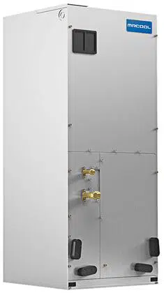
The Universal
®
Series Air Handler (High-ESP) offers the perfect combination of superior product quality, operating
efficiency, operating sound levels, and value for money. It uses the environmentally friendly refrigerant R-410A,
which is chlorine-free to help prevent damage to the ozone layer.
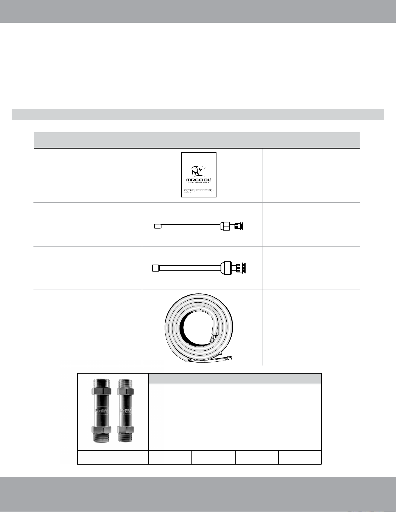
Additional Line Sets & Coupler Kit
If you find the standard size NO-VAC
®
QUICK CONNECT
®
LINE SET length is not sufficient for your application,
additional line sets are available for purchase. You will also
need a NO-VAC
®
COUPLER kit (pictured), which allows line
sets to be connected together to increase the length. The
coupler kit is installed and checked for leaks by following the
same steps described in this manual for connecting the line
set to the indoor air handler (Refer to the NO-VAC
®
QUICK
CONNECT
®
Line Set section on pg. 13 for these steps).
NO-VAC
®
QUICK CONNECT
®
LINE SET Lengths Available
15 FT
25 FT
35 FT
50 FT
To connect the unit
with the liquid pipe
To connect the unit
with the gas pipe
Accessories
OPTIONAL
No-Vac
®
Quick Connect
®
Line Set*
Gas / Liquid
Pipe Assembly
Owner’s Manual
Liquid Side Stub Kit
Gas Side Stub Kit
1
1
1
1
PART LOOKS LIKE...
Please read this manual carefully before installation and keep it for future reference.
Owner’s Manual
UNIVERSAL
™
Series
For more details visit www.MrCool.com
QUANTITY
Unless otherwise stated (as “OPTIONAL”) the air conditioning system includes the following accessories. Use all
of the installation parts and accessories to install the air conditioner. Improper installation may result in water
leakage, electrical shock, fire, and/or equipment failure.
*Pat. https://mrcool.com/mrcool-patents/
Page 7
mrcool.com
Appliance Overview
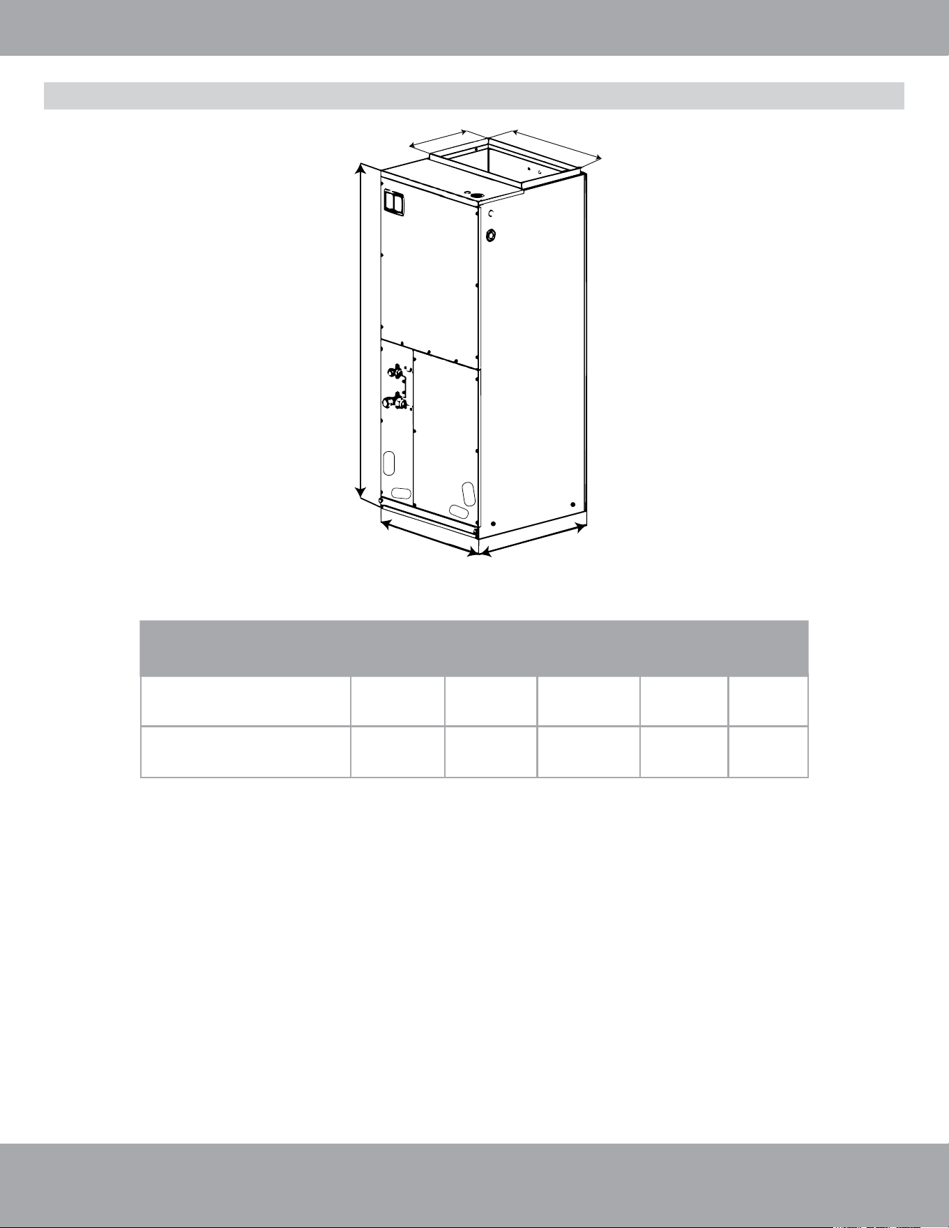
Fig. 1.1
MDUI18024E/MDUI18036E
&
MDUI18048E/MDUI18060E
Unit Dimensions: Inches (mm)
Width
Depth
Height
A
B
21-1/4 in
(540 mm)
21-1/4 in
(540 mm)
48-1/4 in
(1224 mm)
11-5/8 in
(295 mm)
20 in
(508 mm)
Model
MDUI18024E & MDUI18036E
24-3/4 in
(630 mm)
21-1/4 in
(540 mm)
57 in
(1448 mm)
11-5/8 in
(295 mm)
20 in
(508 mm)
MDUI18048E & MDUI18060E
A
H
W
D
B
Unit Dimensions
Page 8
mrcool.com
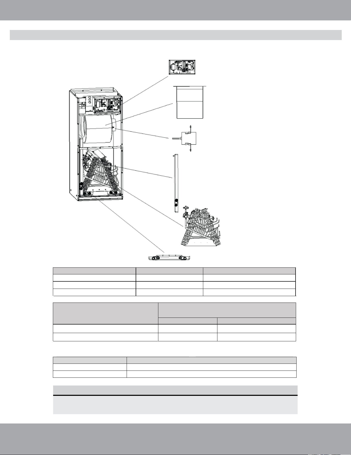
Appliance Overview
Main Parts
Electric Box
Assembly
Centrifugal Fan
Fan Motor
Secondary Drain Pan
Evaporator
Assembly
Primary Drain Pan
Fig. 1.2
Unit: inch (mm)
NOTE
1. Dry coil and filter should be installed based upon nominal tonnage.
2. Use 0.96 as approximate SCFM correction factor for wet coil (optional).
Model Optional electric heater (kW)
MDUI18024E / MDUI18036E
MDUI18048E
MDUI18060E
Cooling capacity (ton)
3.0
4.0
5.0
5-10
15
15
Model
Motor @ 230V~, 60 Hz
1/2
1
3
5
HP FLA
MDUI18024E / MDUI18036E
MDUI18048E / MDUI18060E
Model
Filter size
MDUI18024E / MDUI18036E
MDUI18048E / MDUI18060E
19-5/16 in x 20-5/16 in x 5/8 in (490 mm x 516 mm x 15 mm)
20-11/16 in x 20-5/16 in x 5/8 in (525 mm x 516 mm x 15 mm)
Page 9
mrcool.com
1. Checking Product Received
After receiving the product, please check for any damage caused by transportation. Shipping damage is the
responsibility of the carrier. Verify the model number, specifications, and accessories are correct prior to
installation. The distributor or manufacturer will not accept claims from dealers for transportation damage or
installation of incorrectly shipped units. If an incorrect unit is supplied, it must not be installed and it is to be
returned to the supplier. The manufacturer assumes no responsibility for the installation of incorrectly delivered
units.
2. Before Installation
Carefully read all instructions for the installation prior to installing product. Make sure each step or procedure is
understood and any special considerations are taken into account before starting installation. Assemble all tools,
hardware and supplies needed to complete the installation. Some items or tools may need to be purchased
separately. NOTE: Make sure everything needed to install the product is on hand before starting.
3. Codes & Regulations
This product is designed and manufactured to comply with national codes. It is the installer’s responsibility to install
the product in accordance with such codes and/or any prevailing local codes/regulations. The manufacturer
assumes no responsibilities for equipment installed in violation of any codes or regulations.
4. Replacement Parts
When reporting shortages, damages, or ordering repair parts, be sure to give the complete product model and
serial numbers as stamped on the product. Replacement parts for this product are available through your
contractor or local distributor.
2
Unit Installation
CAUTION
• Before servicing or installing this equipment, the electrical power to this unit must be in the “OFF” position.
• More than one electrical disconnect may exist on this unit. Lock out and tag the switch with a suitable
warning label. Failure to observe this warning may result in electrical shock that can cause personal injury
or death.
• Due to high system pressure and the potential for electrical shock, installation and service work can be
dangerous. Only trained and qualified persons are permitted to install or service this equipment. Observe
all warnings contained in this manual and labels/tags attached to the equipment.
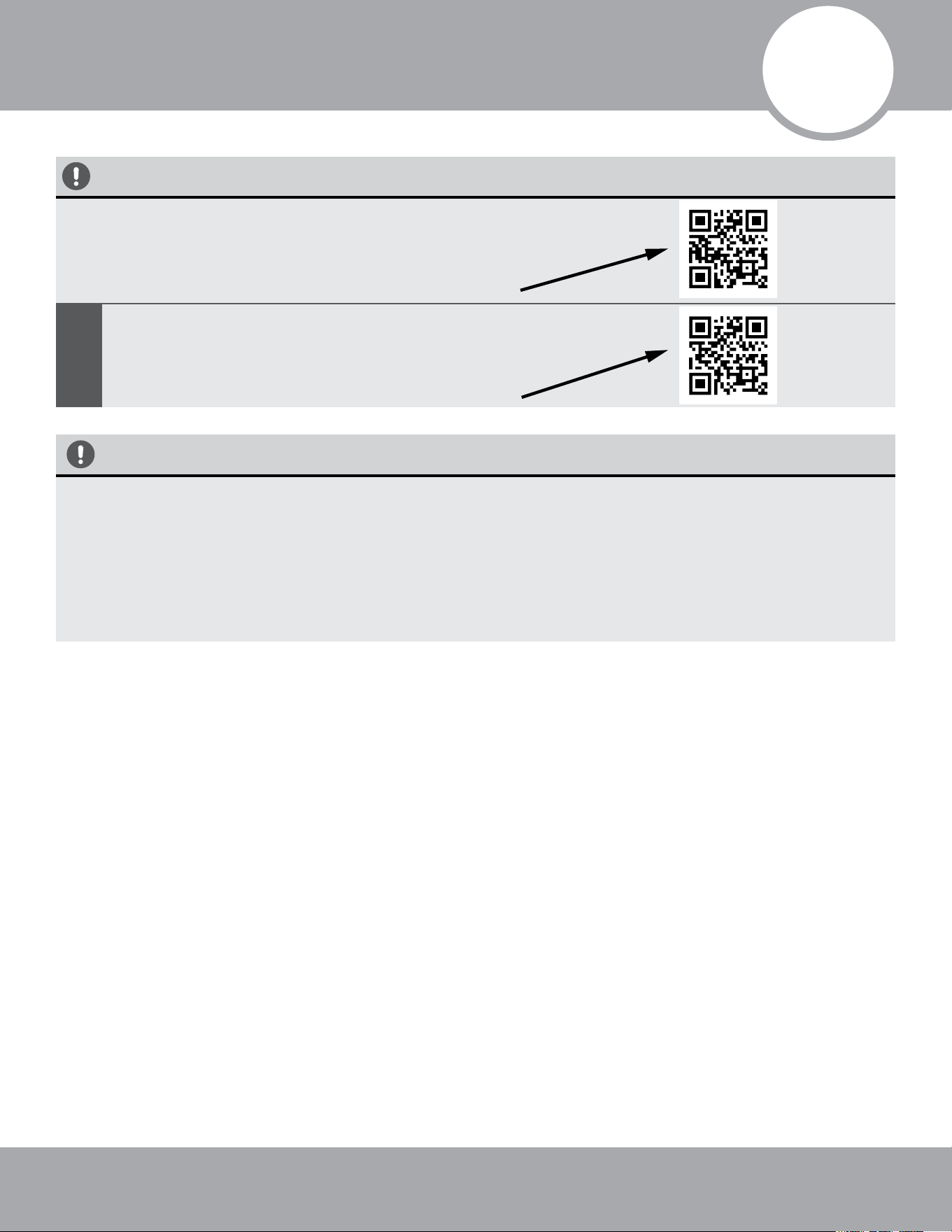
1. The Conventional Weld Line Set Installation
Instructions can be found on page 11
OR
View complete install video by scanning this QR code
2.
No-Vac
®
Quick Connect
®
Line Set*
Installation
Instructions can be found on page 13
OR
View complete install video by scanning this QR code
The Universal™ Series Has 2 Installation Methods
MRCOOL
®
Preferred Method
*Pat. https://mrcool.com/mrcool-patents/
Page 10
mrcool.com
Unit Installation
Installation Location
WARNING
• When installing the air handler, take consideration to minimize the length of refrigerant piping as
much as possible.
• When installing in an area directly over a finished ceiling (such as an attic), installation of an
emergency drain pan is required directly under the unit. See local and state codes for requirements.
• When installing this unit in an area that may become wet, elevate the unit with a sturdy, non-porous
material. In installations that may lead to physical damage (i.e. a garage), it is advised to install a
protective barrier to prevent such damage.
DO NOT install this unit outdoors. This air handler is designed for indoor installation only.
DO NOT operate this product without complete ductwork attached. This air handler is
designed for a complete supply and return ductwork system.
DO NOT install the air handler in a location above or below the condenser that violates the
instructions provided with the condenser. Service clearance is to take precedence. Allow a
minimum of 2 ft (610 mm) service clearance in front of the unit.
DO NOT install the air handler in enclosed areas, such as garages, utility rooms, or parking
areas. Carbon monoxide producing devices (such as an automobile, space heater, gas water
heater, etc.) should not be operated in enclosed areas such as unventilated garages, utility
rooms, or parking areas because of the danger of carbon monoxide (CO) poisoning resulting
from exhaust emissions. If a furnace or air handler is installed in an enclosed area such as a
garage, utility room, or parking area, and a carbon monoxide producing device is operated
therein, there must be direct ventilation to the outside. Adequate ventilation is necessary to
avoid the danger of CO poisoning which can occur if a carbon monoxide producing device
continues to operate in an enclosed area. If these warnings are not followed, carbon
monoxide emission can be (re)circulated throughout the building from the air handler
causing serious illness including permanent brain damage or death.
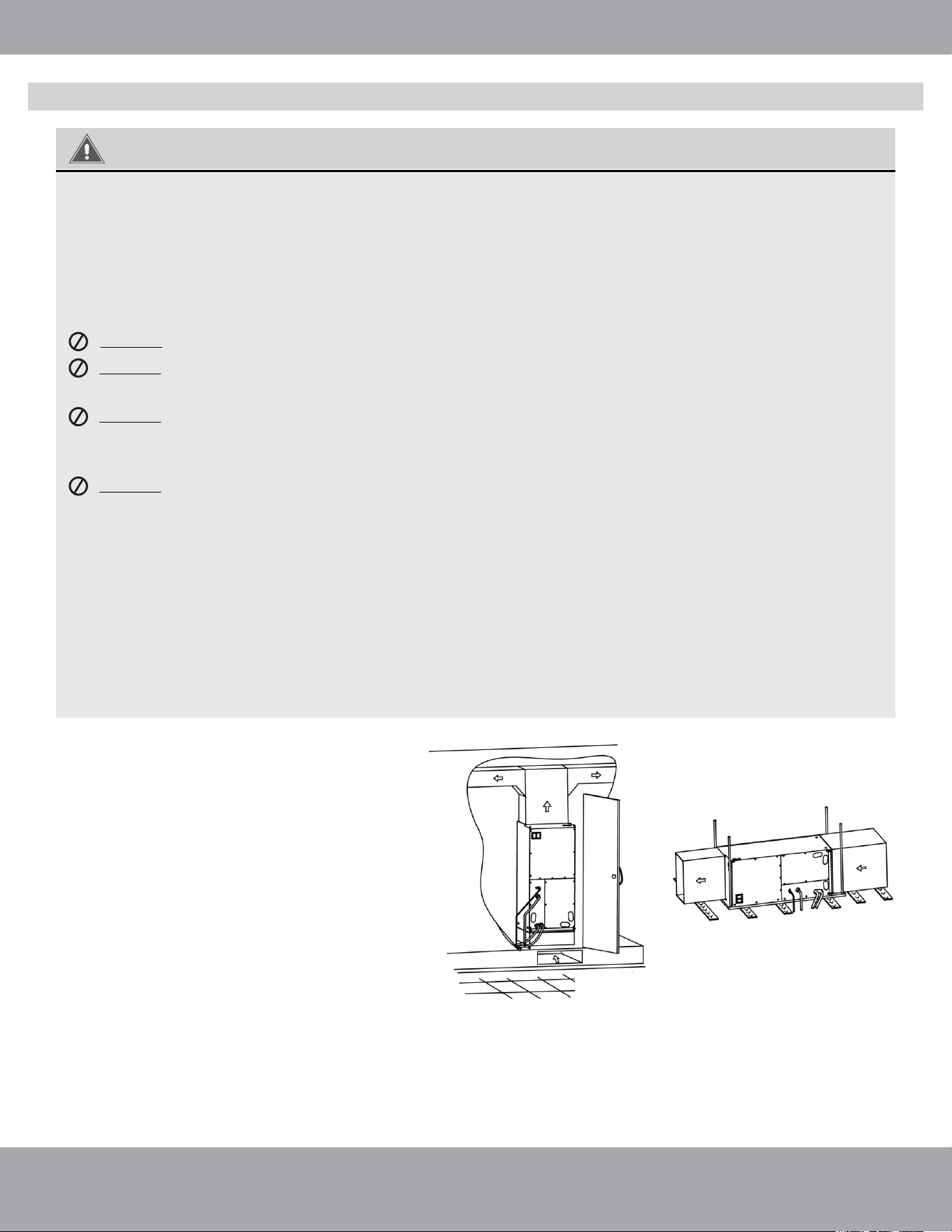
Fig. 2.1
Fig. 2.2
• If air handler is installed as shown in Fig. 2.1,
the air handler should be concealed in a specific
room or space and make sure the air handler is
not accessible to the general public.
• If air handler is installed as shown in Fig. 2.2,
make sure there is enough space for care and
maintenance, and that the height between the air
handler and ground is above 8 ft (2500 mm). Also
make sure the air handler is not accessible to the
general public.
Page 11
mrcool.com
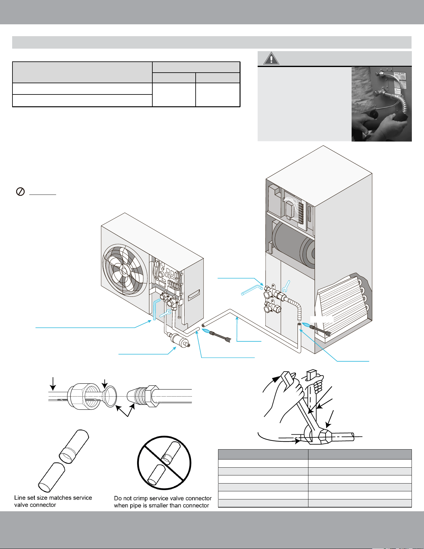
Unit Installation - OPTION 1: Conventional Weld / Flare Line Set
Conventional Line Set Installation
IMPORTANT
Specification of Connection Pipe
Piping Preparation
2. Screw Connection
Copper Piping
Oil Applied (to reduce
friction with the flare nut)
Oil Applied (improves
air-tight seal)
Fig. 2.5
Fig. 2.4
Fig. 2.3
Torque Wrench
Spanner
Piping Union
Flare Nut
MDUI18024E / MDUI18036E (2-3 ton)
Purge with
Nitrogen
Must open stop valves
after pulling vacuum
and before powering
on unit
Weld joint
Weld joint
Air Handler
MRCOOL Universal Series
DC Inverter
Must install lter
drier biow with this
installation type
Must Purge with Nitrogen
before brazing joints
Must Purge with
Nitrogen before
brazing joints
MDUI18048E / MDUI18060E (4-5 ton)
Vapor Pipe Liquid Pipe
3/4 in 3/8 in
In order to prevent the
refrigerant piping from
sweating, you can
insulate them with
closed-cell insulation
foam for refrigerant
line sets which is
readily available.
Pipe diameter (inch)
1/4
3/8
1/2
5/8
3/4
7/8
26-29 ft/lb (35-40 Nm)
33-37 ft/lb (45-50 Nm)
44-48 ft/lb (60-65 Nm)
52-55 ft/lb (70-75 Nm)
59-63 ft/lb (80-85 Nm)
11-22 ft/lb (15-30 Nm)
Tightening torque ft/lb (Nm)
Model
External Diameter (inch)
Open stop valves on the condenser and air
handler with 5 mm & 8 mm allen wrenches
only after the line set connections have been
completed but before powering on the unit.
1. WELD Type Complete Unit Replacement
All cut ends are to be round, clean, and burr free. Failure to follow this
practice increases the chances for refrigerant leakage. Ensure that the
line set size matches service valve connection.
DO NOT crimp the service valve connector when the pipe is
smaller than the connector. See diagram below.
Page 12
mrcool.com
Unit Installation
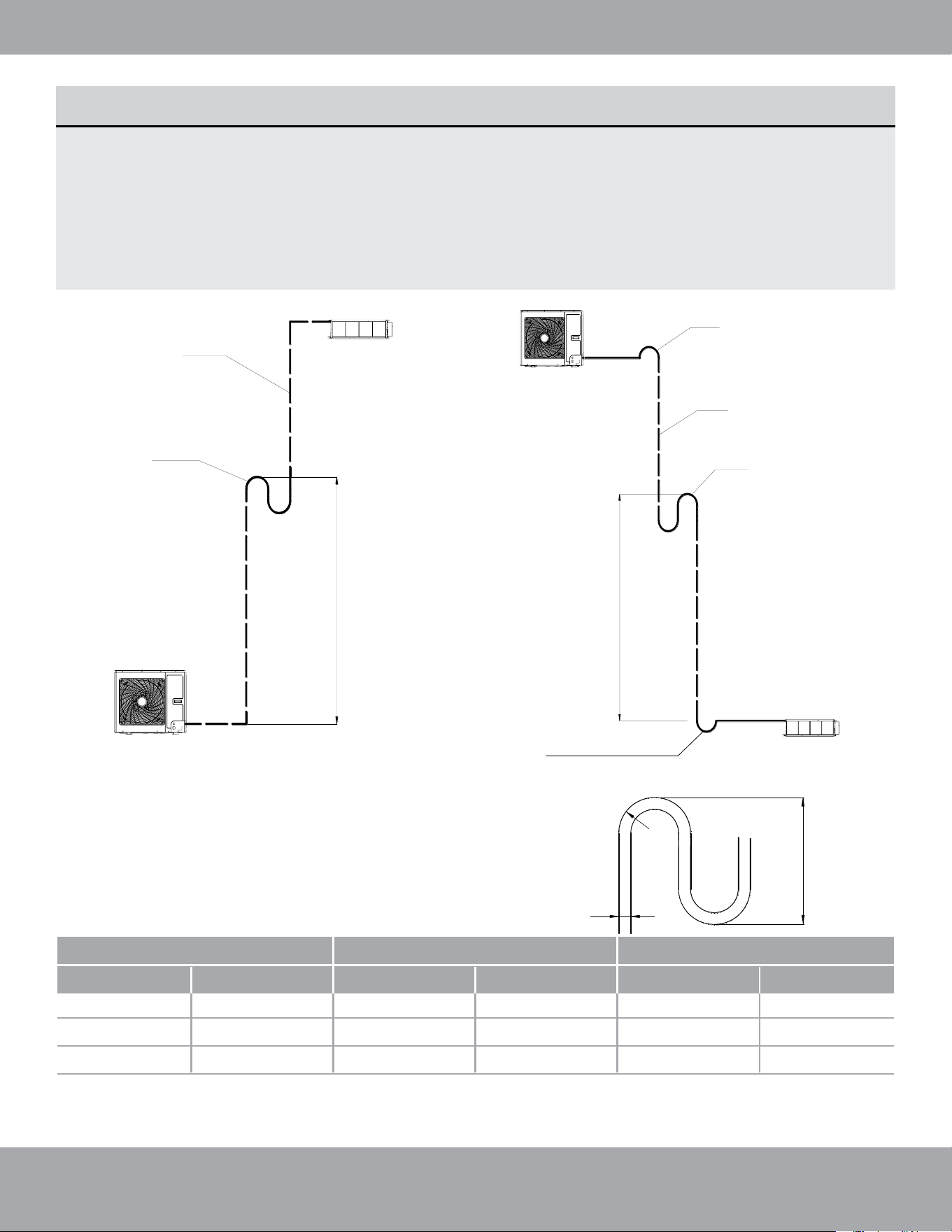
Fig. 2.6
Fig. 2.7
Install an oil
return bend
every 20 ft (6 m)
Oil return bend
System gas pipe
Outdoor unit
Indoor unit
Outdoor unit
Non-return bend
System gas pipe
Oil return bend
Indoor unit
Install an oil
return bend
every 20 ft (6 m)
OIL RETURN BENDS
Add an oil return bend as described below:
If the outdoor unit is installed beneath the indoor unit, install an oil return bend every 20 ft (6 m).
A non-return bend is not needed in this configuration. Please refer to Fig. 2.6 below:
If the outdoor unit is installed above the indoor unit, install an oil return bend every 20 ft (6 m). It
is also necessary to add a non-return bend at the lowest and highest position of the vertical pipe, as
shown below in Fig. 2.7:
Use the following dimensions in Fig. 2.8 to form the oil return bend(s):
C
B
A
A (Pipe Diameter)
B C
Ф12
Ф1/2
≥26
≤150
Ф16
Ф5/8
≥33 ≤150
Ф19
Ф3/4
≥34
≥1
≥1.3
≥1.34
≥5.91
≥5.91
≥5.91
≤150
Fig. 2.8
mmInches mmInches mmInches
•
•
Non-return bend
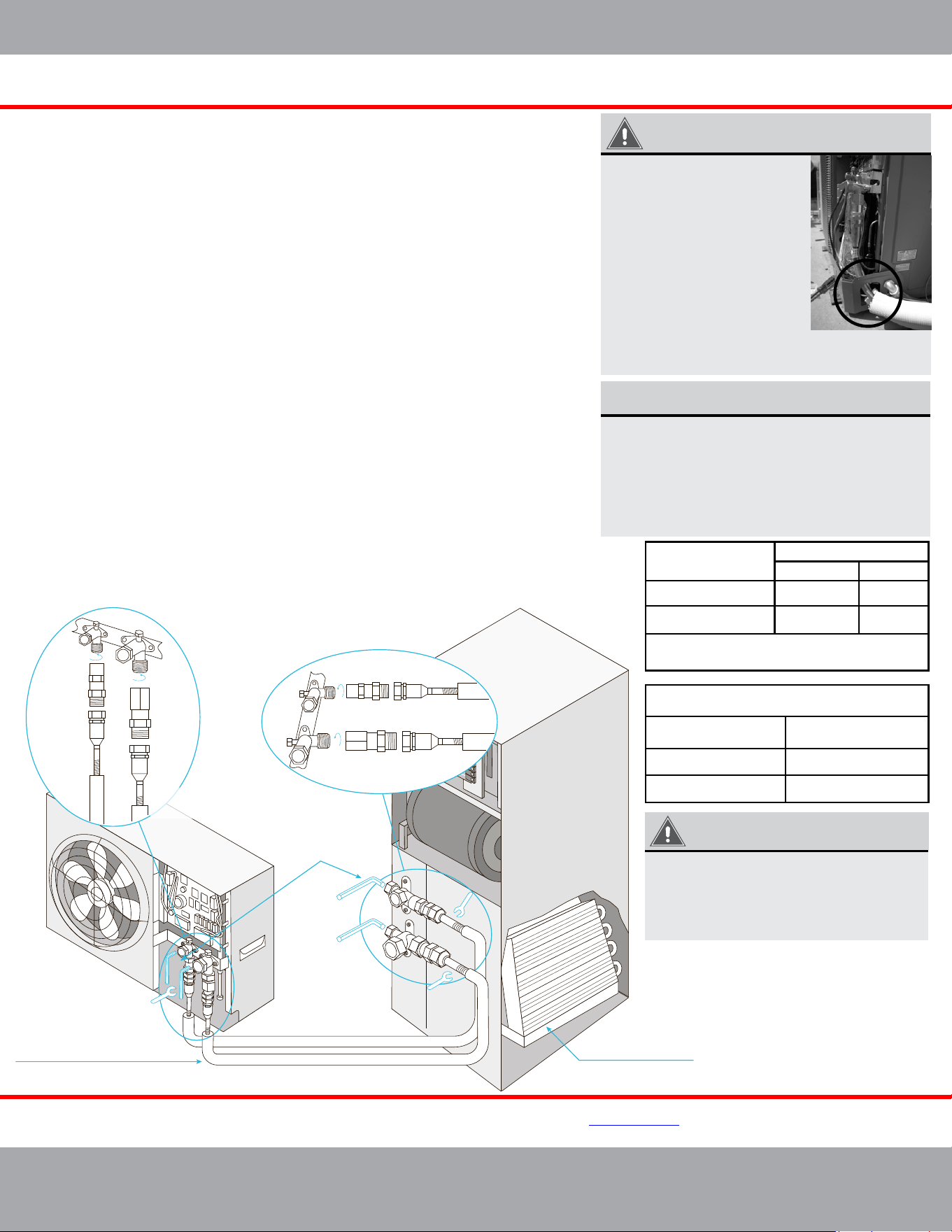
Fig. 2.9
Page 13
mrcool.com
No-Vac
®
Quick Connect
®
Line Set Installation
INSTRUCTIONS FOR USE WITH
NO-VAC™ QUICK CONNECT® LINE SET
SOLD SEPARATELY
37 ft/lb
37 ft/lb
52 ft/lb
52 ft/lb
M1
F1
M1 F1
M2
F2
M2 F2
*1
*1
*2
*2
3/8”
3/8”
3/4”
3/4”
Complete unit replacement
using the No-Vac® Quick Connect® lines
Air Handler
Open the stop/cuto
valves only after
connecting the
refrigerant lines
A-coil Precharged
with R-410A Refrigerant
Connect using precharged
line set with quick connect
ttings in length 15, 25, 35, 50 feet
MRCOOL Universal Series
DC Inverter
KINK RESISTANT, PRECHARGED, SIMPLE SECURE QUICK CONNECT, 100% CONNECTION GUARANTEE
www.mrcool.com
v10-25-2021
IMPORTANT
When running the Line Set
through the knockout hole of
the condenser, it may be
necessary to slightly trim the
line set insulation so it feeds
through the hole freely.
Otherwise, it may be difficult
to connect it to the condenser.
Once the installation is
complete, pack the hole with
neoprene to prevent small
animals and insects from
entering the condenser.
Please read and follow the instruc�ons and diagram below
*
:
1.
Take out matching male connectors M1 and M2.
2.
Remove protec�ve cap with the copper gasket at each stop valve on the DC INVERTER
and ensure the threads are clean and complete.
3.
Tighten the M1 connector to the cutoff valve *1 with a �ghtening force of 37 �/lb (50 Nm).
Tighten the M2 connector to the cutoff valve *2 with a �ghtening force of 52 �/lb (70.5 Nm).
4.
Repeat step 3 for AIR HANDLER at the other end of the LINE SET.
5.
Unroll and route the LINE SET between the AIR HANDLER and the DC INVERTER. Bend the
line set piping by hand to route the line set to suit your applica�on. Use care when bending the
line set. Please refer to Bending the Line Set Sec�on on Pg. 14 for more detailed instruc�ons
on how to properly and safely bend refrigerant piping, as well as the correct bend radius.
6.
Remove the protec�ve caps of the valves at both ends of the LINE SET. Verify that all
threads are clean and complete.
7.
Tighten the LINE SET F1 valve to the M1 Connector (a�ached in step 3) with a force
of 33 �/lb (45 Nm). Tighten the LINE SET F2 valve to the M2 Connector (a�ached in step 3)
with a �ghtening force of 48 �/lb (65 Nm).
8. Repeat this process for the AIR HANDLER at the other end of the LINE SET.
Connec�ons must be made exactly as specified to avoid system leaks and /or damage
9.
At the OUTDOOR UNIT remove the protec�ve cap at the cutoff valve switch and open the
cutoff valve with a hex wrench to release refrigerant into the system. If there is any fizz,
grease or other leakage, then close the valve immediately and check that steps 3 and 7
were done properly. Otherwise, using a sponge or spray bo�le, apply a soapy water solu�on
to the connec�on points to check for micro leaks. If any bubbles form it indicates there is a
leak. If this does occur, close the valve immediately and check that steps 3 and 7 were done
properly and re-�ghten the valves and line set if necessary.
10. A�er the correct connec�on, re-�ghten the
cutoff
valve’s protec�on cap and cover the
M1, M2 and F1, F2 connec�ons with the gray insula�ng sleeve to help prevent
condensa�on.
NOTE ON WRENCHES
The wrench sizes needed for tightening the
No-Vac
®
Quick Connect
®
Line Set are listed
below. However, based on the availability of the
wrench sizes needed, it is recommended to use
two large crescent (adjustable-type) wrenches.
Using one to hold the valve while using the
other wrench to tighten the line set connector.
IMPORTANT
The stop/cutoff valves on the unit must
be opened AFTER connecting the lines
and BEFORE turning on the unit.
Otherwise, operation can cause leakage
and/or damage to the unit.
Piping Size
(Stamped on piping)
Allen/Hex Wrench Sizes Needed
To Open Stop/Cutoff Valves
Wrench Size Required
Standard Metric
Allen Wrench Size
1”3/8”
3/8”
25 mm
1-3/8”3/4”
3/4”
35 mm
5 mm
8 mm
Piping/Valve Size
(Stamped on piping)
Or 2x large crescent (adjustable-type)
wrenches
*Pat. https://mrcool.com/mrcool-patents/
ⱡFailure to follow the instrucons provided could result in severe harm to you, this product, or other property.
The manufacturer, distributor, and seller are not responsible for any harm resulng from the failure to follow
instrucons and the failure to follow these instrucons will void any and all warranes express or implied.
Page 14
mrcool.com
Unit Installation
Drain Connection
2” Minimum
3” Minimum
Flexible Tubing
(Hose or Pipe)
Positive Liquid Seal
(Required)
Unit
Fig. 2.12
Condensate Removal
1. The condensate drain pipe should be connected into a special drain system for the unit.
2. The drain pan has primary and secondary drain connections. Condensate removal is performed by attaching a
3/4 in (19 mm) PVC pipe to the evaporator coil pan and terminated in accordance with local or state plumbing
and HVAC codes. The installation must include a “P” style trap that is located closely to the evaporator coil.
WARNING
DO NOT over-tighten the drain connection in order to prevent damage to the evaporator drain
pan. See the following figure for details of a typical condensate line “P” trap.
DO NOT connect the condensate drain pipe into the waste pipe or other pipelines that are likely
to produce corrosive or peculiar smells. This will prevent odors from entering indoors or
corrupting the unit.
DO NOT connect the condensate drain pipe into the rain pipe. This will prevent rain water from
pouring in and causing property loss or personal injury.
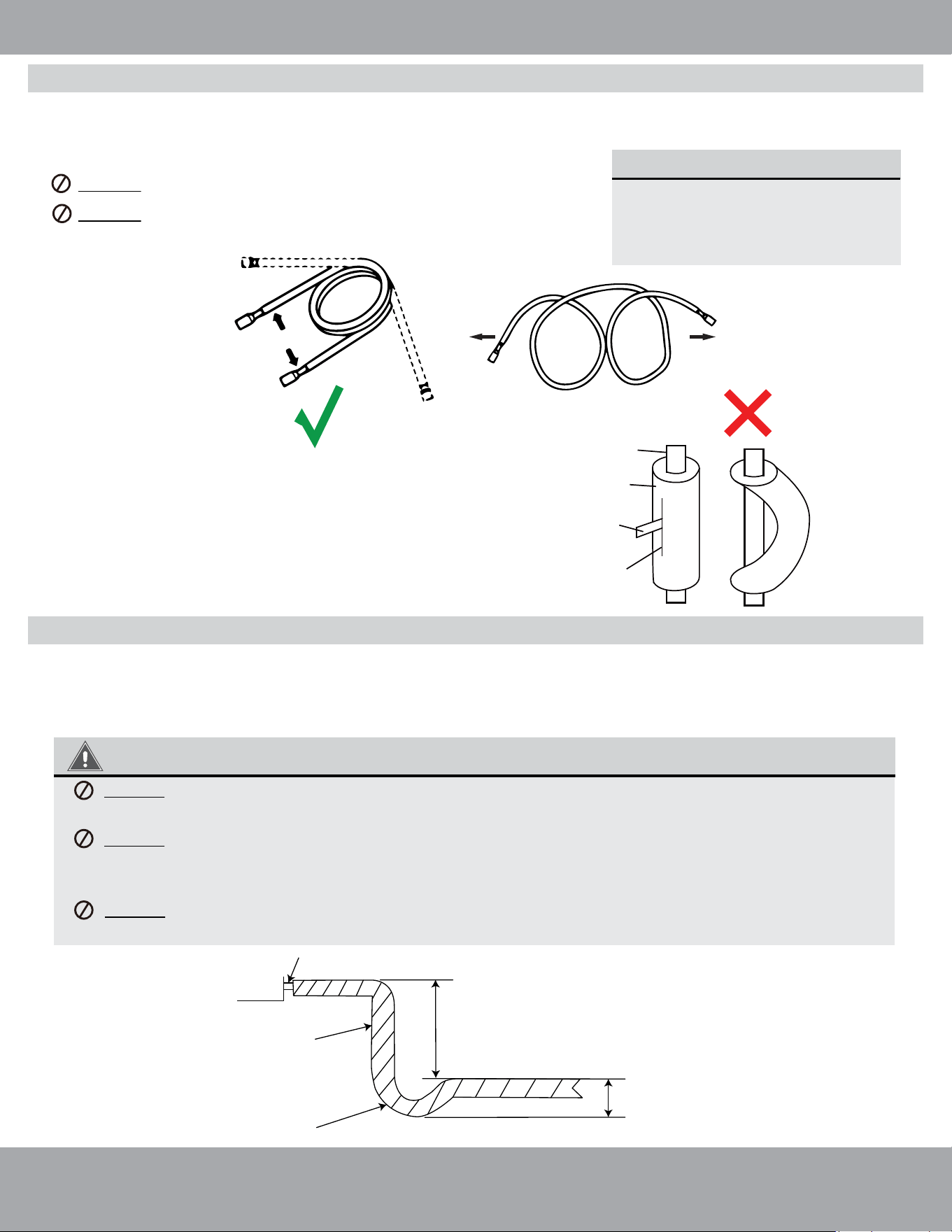
1. Use your hands to bend the pipes. Work carefully not to collapse the pipes during bending.
2. If the pipe is repeatedly bent or extended, it will become hard and difficult to manipulate. Avoid bending
or extending the pipe more than 3 times.
DO NOT bend the pipes in at an angle greater than 90°.
DO NOT bend the pipe excessively, otherwise it will break.
Please refer to Fig. 2.10
MINIMUM BEND RADIUS
When bending connective
refrigerant piping, the minimum
bending radius is 4 in (10 cm).
Refer to Fig. 2.10.
Extend the pipe by unwinding it
Fig. 2.10
3. As shown in Fig. 2.11, use a sharp cutter to cut the pipe
insulation and bend the pipe after it is exposed. After
bending, place the insulation back on the pipe and secure
it with adhesive tape.
Fig. 2.11
Pipe
Insulation
Pipe
Cutter
Cut line
≥4 in (10 cm)
Radius
Bending the Line Set
Page 15
mrcool.com
Unit Installation
IMPORTANT
You must use a compatible heat kit listed in the above chart. Using an incorrectly sized heat kit could
cause the unit to overheat and/or equipment damage.
This air handler is designed for a complete supply and return ductwork system.
Return ductwork:
The return ductwork is to be introduced into the air handler bottom (upflow configuration).
DO NOT dispose of the return ductwork in an area that can introduce toxic or objectionable
fumes and odors into the ductwork.
Return Air Filters:
Each installation must include a return air filter for the air handler or externally using a return air filter grille.
WARNING
DO NOT operate the unit without all ductwork completed and attached.
• Inadequate ductwork that restricts airflow can result in improper performance and failure of the
compressor or heater.
• Ductwork is to be constructed in a manner that limits restrictions and maintains suitable air velocity.
• Ductwork is to be sealed to the unit in a manner that will prevent leakage.
The air handlers listed in this manual do not have a factory installed electric heater. An electric heat kit is
available as an optional accessory. The only heat kits that can be used are the
MHK**U series listed in the
table below. Please refer to installation instructions provided with the heat kit, and in this manual, for the
correct installation procedure.
WARNING
• The electrical characteristics of the air handler, electric heat kit, and the power supply should be
identical. This air handler does not have a factory installed electric heat kit, however, they are
available as an optional accessory. If you plan to install a heat kit, only those in series indicated below
can be used.
DO NOT use an electric heat kit other than those recommended below.
NOTE: When the electric heat kit is turned on, the fan of the air handler must also be on.
MHK05U
MHK08U
5kW heat strip
8kW heat strip
MHK10U 10kW heat strip
Kit # Description
Compatible Heat Kits
2-Ton or 3-Ton
2-Ton or 3-Ton
Tonnage
MHK15U
15kW heat strip
MHK20U 20kW heat strip
4-Ton or 5-Ton
4-Ton or 5-Ton
2-Ton or 3-Ton
Ductwork
Electric Heat Kit Installation (Optional)
Page 16
mrcool.com
Unit Installation
CAUTION
Ensure that all power supply is disconnected prior to installing the heat kit.
A means of strain relief and conductor protection must be provided at the supply wire entrance into cabinet.
Only use copper conductors.
Installation must follow National Electric Code (NEC) and other applicable codes.
If this appliance is installed in an enclosed area such as a garage or utility room with any carbon monoxide
producing appliance, ensure the area is properly ventilated to the outside.
A filter dryer is recommended for installation based on nominal tonnage.
Use 0.96 as approximate SCFM correction factor for wet coil.
•
•
•
•
•
•
•
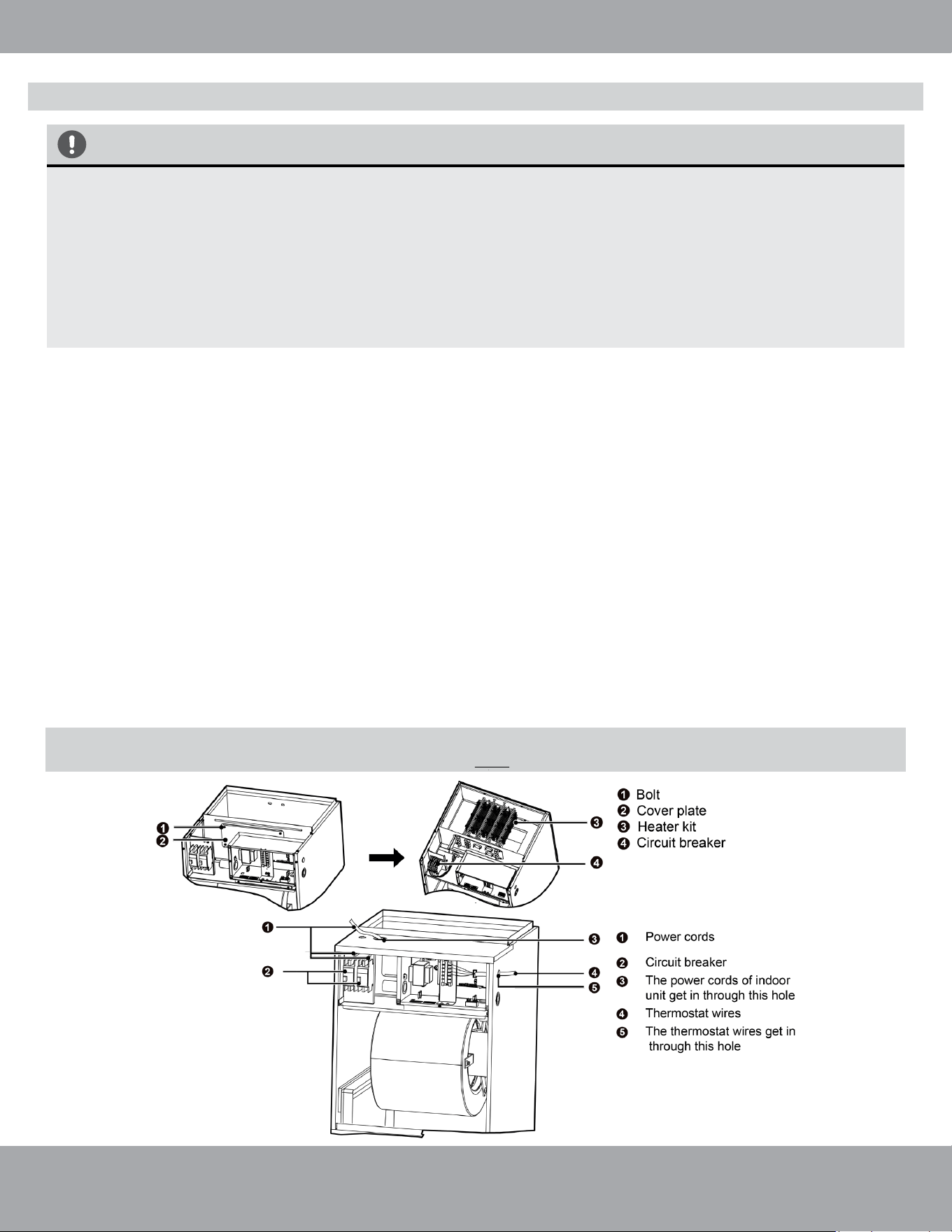
1. Remove the upper access panel from the air handler.
2. Remove the cover plate inside the upper access panel of the air handler.
3. Slide the heat kit into the slot and secure element plate with previously removed screws.
4. Make sure to insert the supporting poles of the heat kit into the supporting hole of the air handler.
5. Connect the quick connection plug and fasten the loose wires by using wire ties.
6. Install the circuit breaker into the mounting rail, break out the appropriate area of the plastic circuit
breaker cover on the access panel of the air handler.
7. a. When installing the MHK05U, MHK08U, or MHK10U (2-3 Ton) use the following steps. Connect the
power from the Circuit Breaker Panel to L1 and L2 of the circuit breaker included with the electric heat
kit.
b. When installing the MHK15U and MHK20U (4-5 Ton) use the following steps. Connect two separate
lines of power from the Circuit Breaker Panel to L1 and L2 of the two circuit breakers included with the
electric heat kit.
c. When connecting the electric heat kit to the air handler, use the Molex Plug Wiring Harness from the
electric heat kit and attach it to the Molex Plug Wiring Harness coming from air handler’s PCB board.
d. Replace access panel and check operation.
Fig 2.13
NOTE: The Molex Plug Connection will power the air handler. So, a separate source of incoming
power for L1 & L2 terminals on the air handler is NOT needed when using an electric heat kit.
Electric Heat Kit Installation (continued)
NOTE
Refer to the Universal Condenser Manual for the Dip Switch instructions and settings for the condenser.
Fig 2.14
mrcool.com
Page 17
Unit Installation
Follow these instructions during unit installation in order
to enable a Universal
®
Series 3-ton condenser and air
handler split system to operate at 2-ton capacity.
DO NOT attempt this conversion while the unit
is powered on.
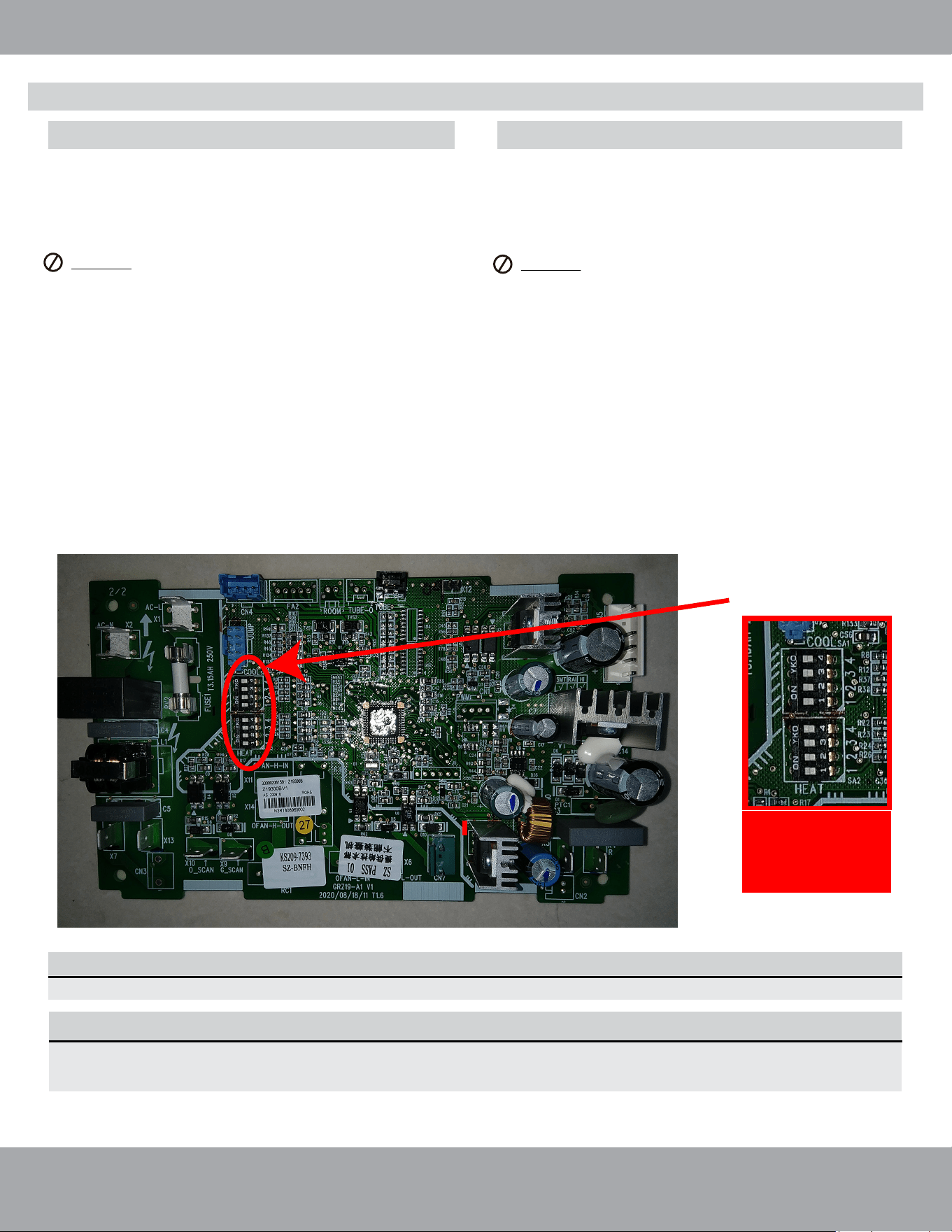
1. Locate the capacity dip switch on the air handler
main board. The capacity dip switch is circled on the
photo below.
2. The default position of the capacity dip switch is 1, 2,
& 4 ‘Up’ and 3 ‘Down’ on both the SA2 and SA1
switches.
3. The default position of the capacity dip switch is 36K.
4. To activate the 24K capacity, flip capacity dip switch 2
& 4 on SA2 and SA1 to Down. Flip capacity dip switch
3 on SA2 and SA1 to Up.
Follow these instructions during unit installation in order
to enable a Universal
®
Series 5-ton condenser and air
handler split system to operate at 4-ton capacity.
DO NOT attempt this conversion while the unit
is powered on.
1. Locate the capacity dip switch on the air handler
main board. The capacity dip switch is circled on the
photo below.
2. The default position of the capacity dip switch is 2, 3,
& 4 ‘Up’ and 1 ‘Down’ on both the SA2 and SA1
switches.
3. The default position of the capacity dip switch is 60K.
4. To activate the 48K capacity, flip capacity dip switch
1, 3, & 4 on SA2 and SA1 to Down. Flip capacity dip
switch 2 on SA2 and SA1 to Up.
Location of Dip Switch on
Air Handler Main Board
This is an example for
switch location only.
Refer to the
illustations above for
settings.
Converting a 3-Ton Unit to 2-Ton
Converting a 5-Ton Unit to 4-Ton
Air Handler Field Conversion
NOTE ON DIP SWITCH ORIENTATION
Depending on your application, and the position the unit is mounted in, the DIP Switches may be upside
down.
Unit Installation
mrcool.com
Page 18
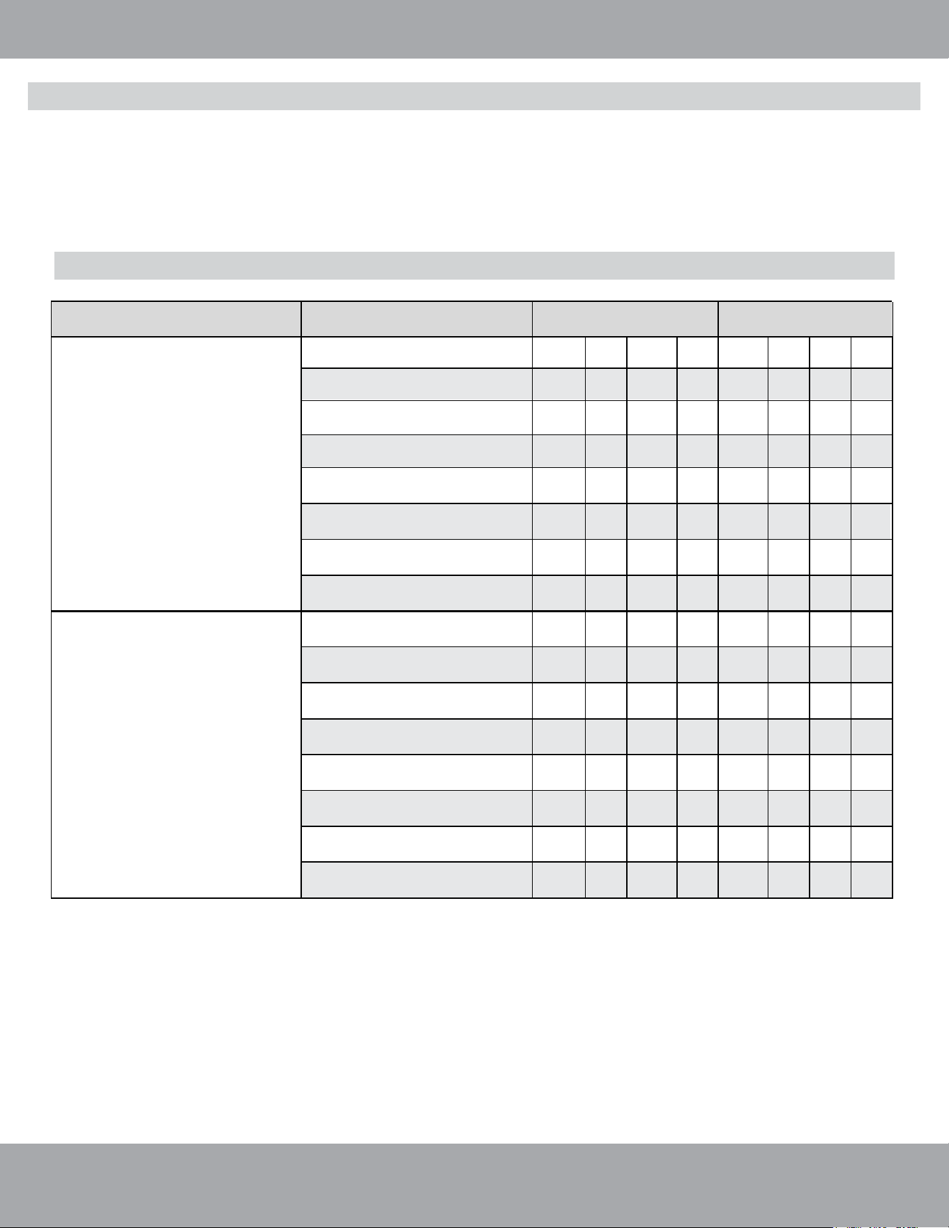
The High ESP Air Handler comes equipped with an 8-speed fan. Below are settings for the dip switches
(found on the indoor main control board) in order to adjust the fan to each of the speeds for the 2-3
Ton unit (For the 4-5 Ton unit, please refer to the following page). The higher the level, the
higher the speed of the indoor unit fan. The default setting is Level 4.
NOTE: Dip switch settings must be configured before powering on the unit.
Fan Speed/Dip Switch Settings for MDUI18024E/MDUI18036E (2-3 Ton)
Model
Level
Heat (SA2)
Cool (SA1)
24K Indoor Unit
Dip Switches
1
0
0
0
0
0
0
0
Level 2
1
0
0
1
0
0
0
0
Level 3 1 0 1 0 0 0 0 0
Level 4 (Default) 1 0 1 1 0 0 0 0
Level 5 1 1 0 0 0 0 0 0
Level 6 1 1 0 1 0 0 0 0
Level 7 1 1 1 0 0 0 0 0
Level 8 1 1 1 1 0 0 0 0
Level 1 0 0 0 0 0 0 0 0
Level 2 0 0 0 1 0 0 0 0
Level 3 0 0 1 0 0 0 0 0
Level 4 (Default) 0 0 1 1 0 0 0 0
Level 5
0 1 0 0 0 0 0 0
Level 6
0 1 0 1 0 0 0 0
Level 7 0 1 1 0 0 0 0 0
Level 8 0 1 1 1 0 0 0 0
36K Indoor Unit
Dip Switches
NOTE: 0 means position dip switch to on, 1 means position dip switch to number.
Level 1
Set Indoor Fan Speed/Dip Switch Configuration
Unit Installation
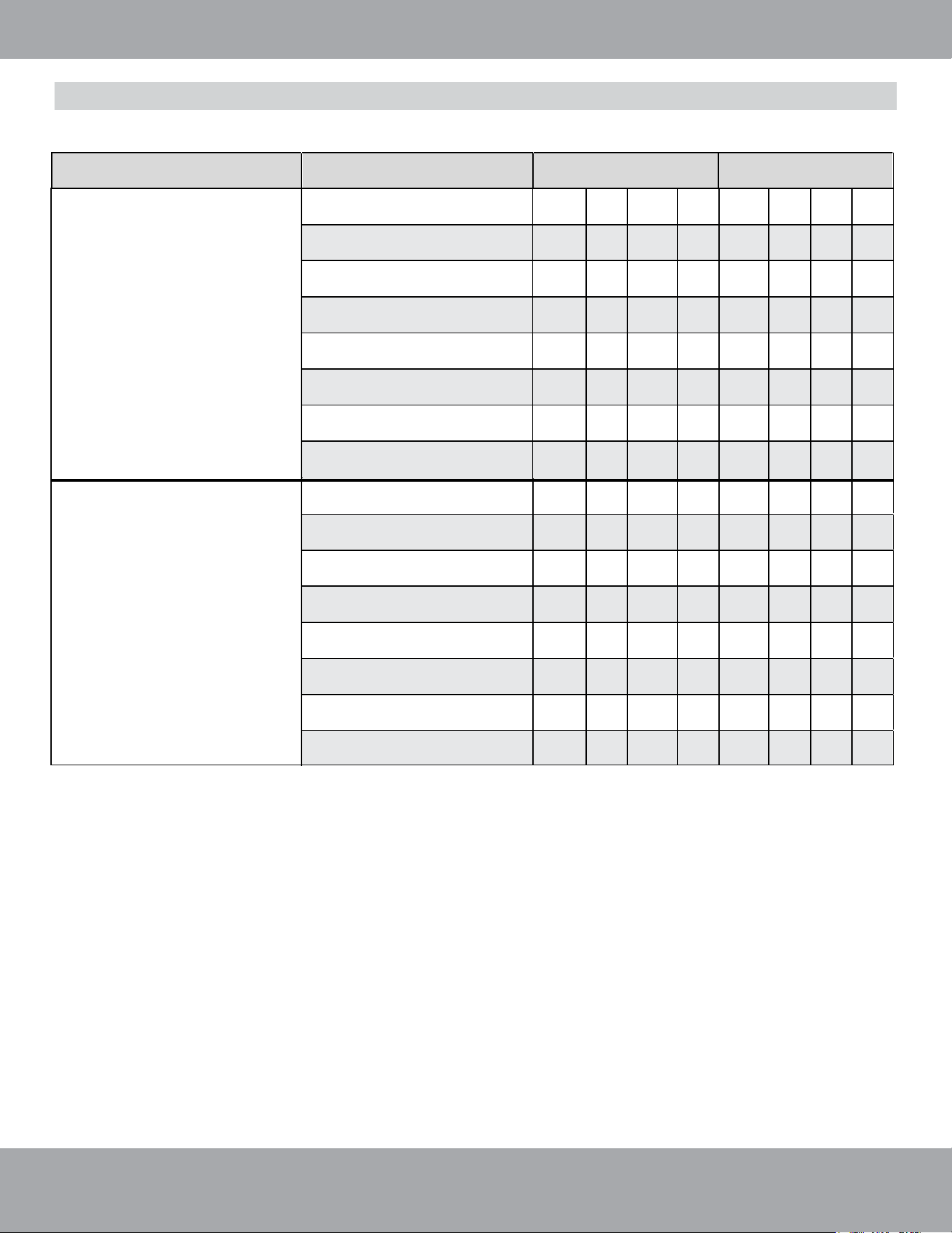
Fan Speed/Dip Switch Settings for MDUI18048E/MDUI18060E (4-5 Ton)
mrcool.com
Page 19
Model Level Heat (SA2) Cool (SA1)
48K Indoor Unit
Dip Switches
Level 1 1 0 0 0 0 0 0 0
Level 2 1 0 0 1 0 0 0 0
Level 3 1 0 1 0 0 0 0 0
Level 4 (Default) 1 0 1 1 0 0 0 0
Level 5 1 1 0 0 0 0 0 0
Level 6 1 1 0 1 0 0 0 0
Level 7 1 1 1 0 0 0 0 0
Level 8 1 1 1 1 0 0 0 0
60K Indoor Unit
Dip Switches
Level 1 0 0 0 0 0 0 0 0
Level 2 0 0 0 1 0 0 0 0
Level 3 0 0 1 0 0 0 0 0
Level 4 (Default) 0 0 1 1 0 0 0 0
Level 5 0 1 0 0 0 0 0 0
Level 6
0
1
0
1
0
0
0
0
Level 7 0 1 1 0 0 0 0 0
Level 8
0
1
1
1
0
0
0
0
NOTE: 0 means position dip switch to on, 1 means position dip switch to number.
Speed 1
Speed 2
Speed 3
Speed 4
Speed 5
Speed 6
Speed 7
Speed 8
Unit Installation
mrcool.com
Page 20
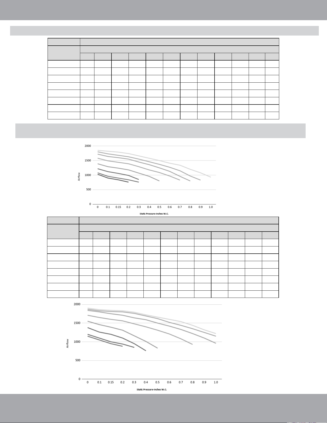
Air Flow Volume Under Different ESP & Fan Speed: MDUI18024E/MDUI18036E (2-3 Ton)
Model MDUI18024E
Level
Static pressure(Inches W.C.)
0
0.1
0.15
0.2
0.3
0.4
0.5
0.6
0.7
0.8
0.9
1.0
Speed 1(CFM)
1030
900
840
-
-
-
-
-
-
-
-
-
Speed 2(CFM)
1080
960
900
840
-
-
-
-
-
-
-
-
S
peed 3(CFM
)
1220
1120
1060
990
850
-
-
-
- - - -
Speed 4(CFM)
1390
1290
1240
1180
1070
960
-
-
-
-
-
-
Speed 5(CFM)
1580
1490
1440
1390
1290
1180
1090
970
830
-
-
-
Speed 6(CFM)
1720
1640
1600
1550
1450
1360
1250
1130
960
-
-
-
Speed 7(CFM)
1800
1730
1680
1630
1550
1460
1370
1270
1150
970
830
Speed 8(CFM)
1850
1820
1790
1740
1660
1580
1500
1410
1340
1200
1080
930
Speed 1
Speed 2
Speed 3
Speed 4
Speed 5
Speed 6
Speed 7
Speed 8
Model
MDUI18036E
Level
Static pressure(Inches W.C.)
0
0.1
0.15
0.2
0.3
0.4
0.5
0.6
0.7
0.8
0.9
1.0
Speed 1(CFM)
1150
1050
950
880
-
-
-
-
-
-
-
-
Speed 2(CFM)
1200
1100
1000
940
850
-
-
-
-
-
-
-
Speed 3(CFM)
1380
1260
1200
1100
950
-
-
-
-
-
-
-
Speed 4(CFM)
1550
1460
1390
1310
1160
1010
830
-
-
-
-
-
Speed 5(CFM)
1710
1650
1600
1560
1480
1400
1310
1210
1080
930
-
-
Speed 6(CFM)
1840
1800
1750
1710
1640
1590
1500
1420
1330
1220
1100
960
Speed 7(CFM)
1870
1830
1810
1800
1760
1690
1620
1520
1440
1350
1250
1150
Speed 8(CFM)
1900
1860
1840
1830
1790
1720
1660
1600
1540
1440
1320
1220
NOTE: Please refer to the tables above & below for fan speed selection relative to static pressure.
“-” in the table indicate speeds that are not allowed to be used.
Unit Installation
mrcool.com
Page 21
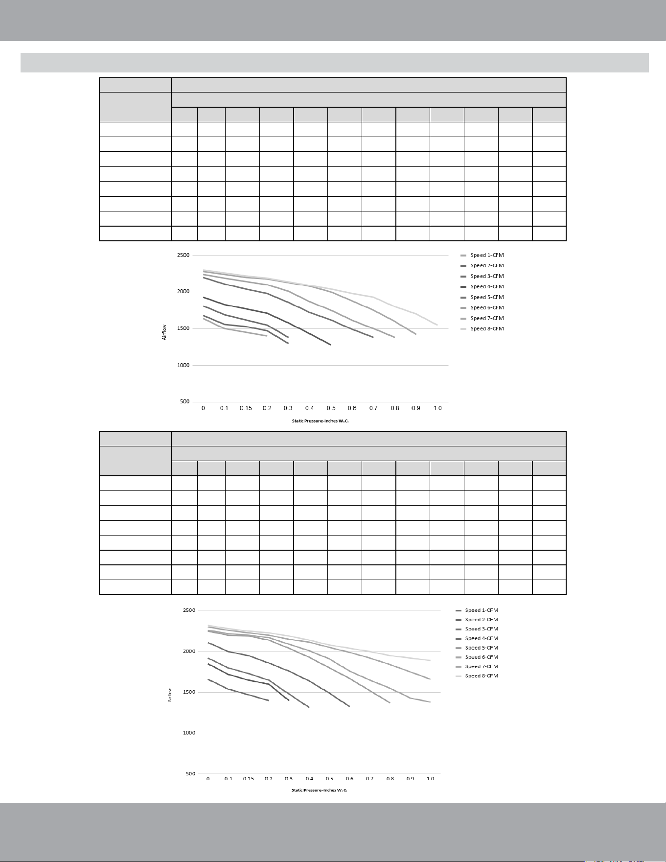
Air Flow Volume Under Different ESP & Fan Speed: MDUI18048E/MDUI18060E (4-5 Ton)
Speed 1
Speed 2
Speed 3
Speed 4
Speed 5
Speed 6
Speed 7
Speed 8
Speed 1
Speed 2
Speed 3
Speed 4
Speed 5
Speed 6
Speed 7
Speed 8
Model
MDUI18048E
Level
Static pressure(Inches W.C.)
0
0.1
0.15
0.2
0.3
0.4
0.5
0.6
0.7
0.8
0.9
1.0
Speed 1(CFM)
1640
1500
1450
1350
-
-
-
-
-
-
-
-
Speed 2(CFM)
1680
1560
1500
1380
1300
-
-
-
-
-
-
-
Speed 3(CFM)
1810
1690
1620
1550
1380
-
-
-
-
-
-
-
Speed 4(CFM)
1930
1830
1770
1710
1580
1430
1280
-
-
-
-
-
Speed 5(CFM)
2200
2110
2040
1980
1860
1720
1620
1490
1380
-
-
-
Speed 6(CFM)
2
240
2190
2145
2100
2010
1870
1750
1615
1500
1380
-
-
Speed 7(CFM)
2280
2240
2200
2180
2130
2080
2000
1880
1750
1600
1420
Speed 8(CFM)
2300
2260
2220
2190
2140
2090
2040
1980
1930
1800
1700
1550
Model
MDUI18060E
Level
Static pressure(Inches W.C.)
0
0.1
0.15
0.2
0.3
0.4
0.5
0.6
0.7
0.8
0.9
1.0
Speed 1(CFM)
1660
1540
1470
1400
-
-
-
-
-
-
-
-
Speed 2(CFM)
1850
1720
1650
1600
1400
-
-
-
-
-
-
-
Speed 3(CFM)
1920
1800
1730
1650
1480
1315
-
-
-
-
-
-
Speed 4(CFM)
2110
2000
1950
1860
1760
1640
1490
1325
-
-
-
-
Speed 5(CFM)
2250
2200
2190
2140
2040
1930
1800
1670
1520
1370
-
-
Speed 6(CFM)
2260
2220
2200
2170
2090
2010
1910
1760
1650
1550
1430
1380
Speed 7(CFM)
2300
2260
2230
2200
2150
2115
2050
1990
1920
1840
1750
1660
Speed 8(CFM)
2320
2280
2250
2230
2190
2140
2080
2040
2000
1950
1920
1890
Page 22
mrcool.com
Unit Installation
WARNING Before performing electrical work, read the following regulations
Electrical installation must be conducted by professionals in compliance with local laws,
regulations, and this installation manual.
Never artificially extend the length of a power cord.
The electric circuit must be equipped with a circuit breaker and air switch. Both must have
sufficient capacity.
Unit operating power must be within the nominal range stated in the instruction manual.
The air conditioner circuit should be at least 5 ft (1.5 m) away from any flammable surface.
The external power cords, the thermostat wires, and the thermostat must be effectively fixed.
The external power cords, thermostat wires, and thermostat must NOT directly contact any hot
objects. For example: they must not come into contact with chimney pipes, warm gas pipes or
other heat producing objects.
The external power cords, thermostat wires, and thermostat must NOT be squeezed. Never pull,
stretch, or bend the wires.
The external power cords, thermostat wires, and thermostat must NOT collide with any metal
beam or edge on the ceiling, or touch any metal burrs or sharp metal edges.
Connect wires in accordance to the circuit diagram labeled on the unit or electric box. Screws must
be tightened. Slipped screws must be replaced by specialized flat-head screws.
Wiring terminals should be connected securely to the terminal board. Loose connections can pose
a safety risk.
Only use the power cables that are delivered along with the air conditioner.
After the electrical installation is finished, use wire clamps to secure the power cords and
thermostat wires. Make sure the wires are not clamped too tightly.
The wire gauge of the power cord should be sufficiently large. A damaged power cord or other
wires must be replaced by specialized wires. Wiring must be completed according to national
wiring rules and regulations.
This product is factory shipped for use with a 208/230V-1Ph-60Hz electrical power supply. This air
handler must not be reconfigured to operate with any other power supply.
The unit must have an uninterrupted, unbroken electric grounding to minimize the possibility of
personal injury if an electric fault occurs. The electric grounding circuit may consist of an
appropriate sized power cord connected with the grounding piece, located in the unit control box,
and also connecting to the building electric service panel. Other methods of grounding are
permitted if performed in accordance with the National Electric Code (NEC), American National
Standards Institute (ANSI), National Fire Protection Association (NFPA) 70, and local/state codes. In
Canada, electric grounding conforms to the Canadian electric code CSA c22.1. Failure to observe
this warning can result in electrical shock that can cause personal injury.
DO NOT change the power cables arbitrarily.
DO NOT change the length and terminals of the power cables.
DO NOT draw power from another power circuit. Use a specialized power circuit for the unit.
Vacuum Lines
Electrical Regulations
1.
2.
3.
4.
5.
6.
7.
8.
9.
10.
11.
12.
13.
14.
15.
16.
Electrical Connection
***Disclaimer: Wiring must meet code specs according to the capacity/tonnage of the unit.***
Page 23
mrcool.com
Unit Installation
Indoor Unit Model Power Supply
Max. Overcurrent
Protection (A)
208/230V (60 Hz)
15 amps4 amps
MDUI18024E/MDUI18036E
Min. Circuit
Ampacity
Electrical Parameters
208/230V (60 Hz)
15 amps
8 amps
MDUI18048E/MDUI18060E
1. The fuse is located on the main board.
2. Install a circuit breaker at every power terminal near the units (indoor unit and thermostat) with at least
0.12 in (3 mm) contact gap. Both units must reach the plug.
3. Circuit breaker and power cord specifications listed in the above table are determined based on the
maximum power input of the units.
4. Specifications of power cords listed in the above table are applicable in a working condition where the
ambient temperature is 104°F (40°C) and multi-core copper cable (e.g. YJV copper cable, with insulated PE
and PVC sheath) is protected by a conduit, and is resistant to 194°F (90°C) in maximum (see IEC
60364-5-52). If working conditions change, please adjust the specifications according to national standards.
5. Specifications of circuit breaker are based on a working condition where the working temperature is 104°F
(40°C). If working conditions change, please adjust the specifications according to national standards.
6. The gauge of thermostat wire between the indoor unit and thermostat should be no less than 18 AWG
and at least 6 strand to ensure a proper connection. Please select a proper length of wire according to local
conditions. The maximum connection length is 98 feet (30 m).
Connecting the Power Cord & Communication Wire
WARNING
1. Before work begins, please check to ensure the unit and thermostat are powered “OFF”.
2. Match the terminal numbers and wire colors with the colors indicated in the indoor unit.
3. Incorrect wiring connections could burn the electrical components.
4. Connect the wires securely to the wiring box. Incomplete installation may lead to a fire hazard.
5. Please use wire clamps to secure the external covers of connecting wires. (Insulators must be
clamped securely; otherwise, electrical leakage may occur.)
6. Ground wire should be connected securely.
7. High and low voltage wires should be led through different rubber rings of the electric box cover.
8. High and low voltage wires should be secured separately. Secure the high voltage wires with large
clamps and the low voltage wires with small clamps.
9. Use screws to tighten the thermostat wires and power cords of the unit on the terminal board. An
improper connection could create a fire hazard.
10. If the power cords and thermostat wires are not correctly connected, the air conditioner could suffer
damage.
11. Ground the system by connecting the ground wire.
12. The units should comply with all applicable local and national rules and regulations on power
consumption.
13. When connecting the power cord, make sure the phase sequence of the power supply matches
with the corresponding terminals, otherwise the compressor will be reversed and operate
abnormally.
DO NOT bundle the thermostat wires or lay them side by side, otherwise errors will occur.
Electrical Connection
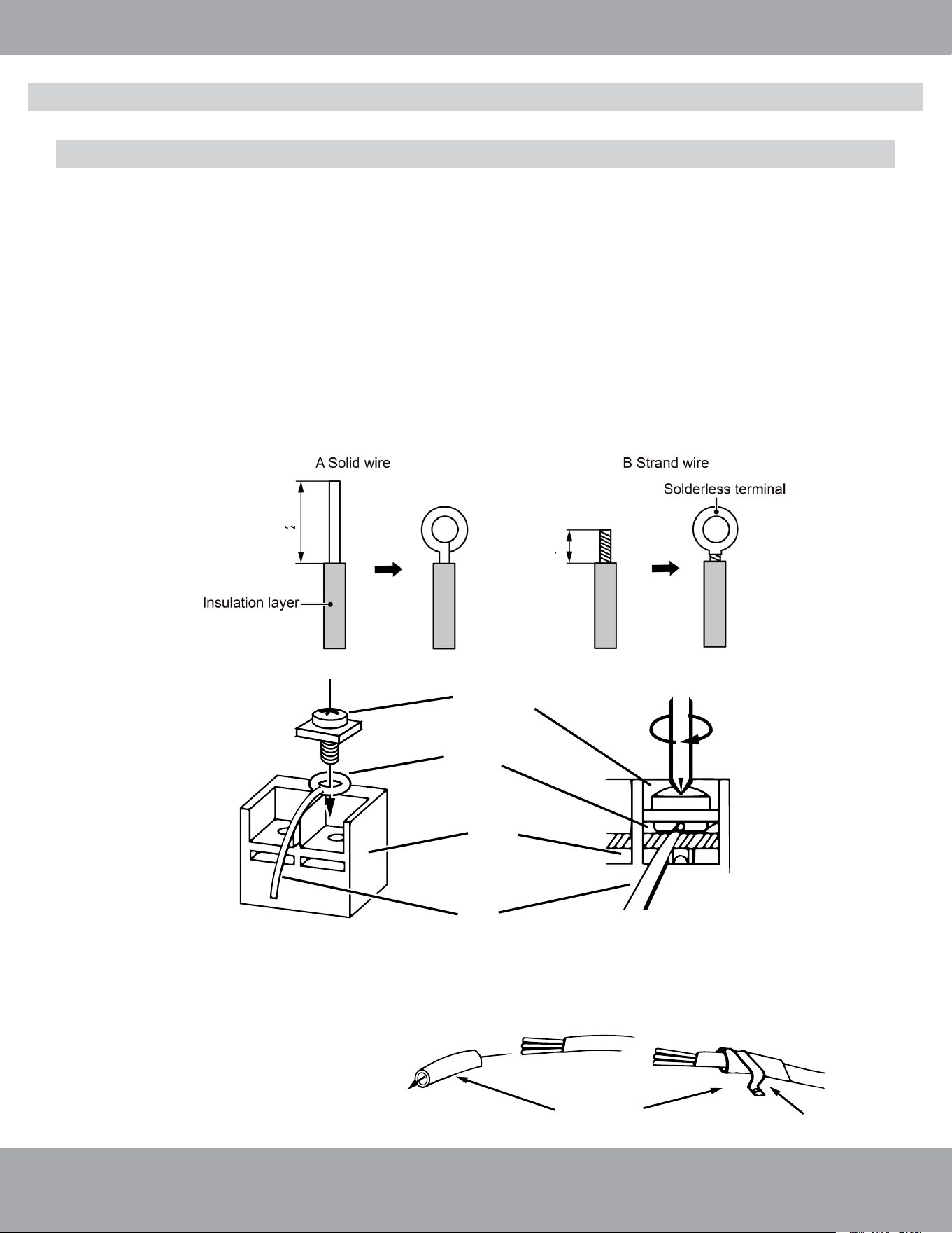
Screw with
Special Fastener
Round
Terminal
Wire
Terminal
Board
Fig. 2.16
Page 24
mrcool.com
Unit Installation
Connecting the Power Cord & Thermostat Wires
For solid wires (Refer to Fig. 2.15 A):
1. Use wire cutters to cut off the wire end and then peel away about 1 in (25 mm) of the insulation layer.
2. Use a screwdriver to unscrew the terminal screw on the terminal board.
3. Use nippers to bend the solid wire into a ring that fits the terminal screw.
4
. Form a proper ring and attach to the terminal board. Use a screwdriver to tighten the terminal screw.
For braided/strand wires (Refer to Fig. 2.15 B & Fig. 2.16):
1. Use wire cutters to cut off the wire end and then peel away about 3/8 in (10 mm) of the insulation layer.
2. Use a screwdriver to unscrew the terminal screw on the terminal board.
3. Use a round terminal fastener or clamp to secure the round terminal firmly on the peeled wire end.
4
. Locate the round terminal conduit. Use a screwdriver to replace it and tighten the terminal screw (as
shown in Fig. 2.16).
Fig. 2.15
For all terminal wiring (Refer to Fig. 2.18 & 2.19 (2-3 ton unit) or Fig. 2.20 & 2.21 (4-5 ton unit) on
the next page):
5.
Lead the connection wire and power cord through the insulation tube. Then secure
the wires with wire clamps (as shown in Fig. 2.17).
Fig. 2.17
Cord Clamp
Insulation Tube
1 in (25 mm)
3/8 in (10 mm)
Electrical Connection
Page 25
mrcool.com
Unit Installation
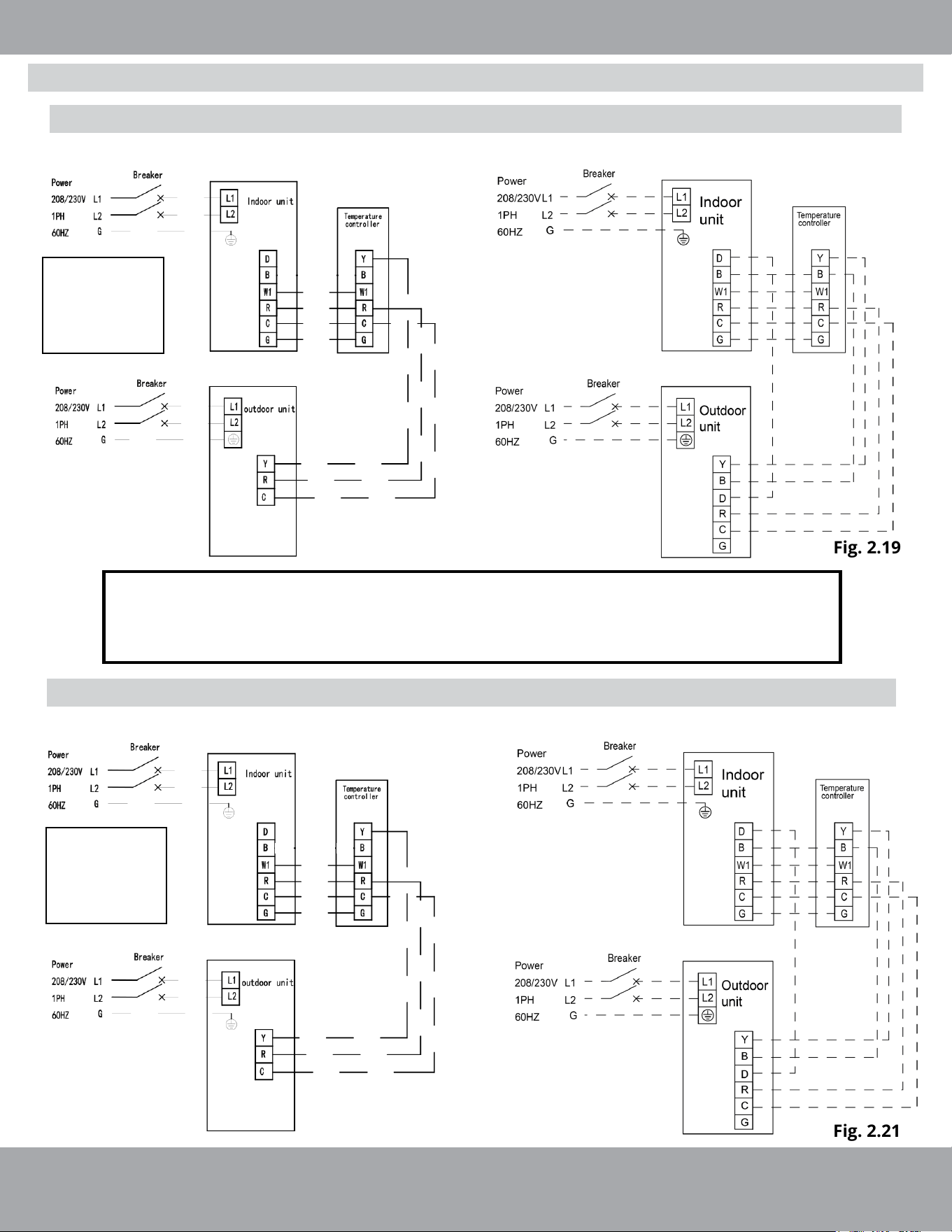
Electrical wiring of ESP Air Handler MDUI18024E/MDUI18036E (With & Without Heat Pump)
High ESP Air Handler w/cooling only condenser
High ESP Air Handler w/heat pump condenser
Electrical wiring of ESP Air Handler MDUI18048E/MDUI18060E (With & Without Heat Pump)
High ESP Air Handler w/cooling only condenser
High ESP Air Handler w/heat pump condenser
Fig. 2.18
Fig. 2.19
Fig. 2.20
Fig. 2.21
NOTE: B and D
terminals are
not used in
cooling only
condenser
NOTE: B and D
terminals are
not used in
cooling only
condenser
NOTES:
Y - Compressor control signal for outdoor unit B - 4-way valve control signal (energized in heating mode)
D - Defrosting signal R - 24V AC Power Supply
C - 24V common G - Fan signal for indoor unit
W1 - Heater Control signal
Electrical Connection
Page 26
mrcool.com
Unit Installation
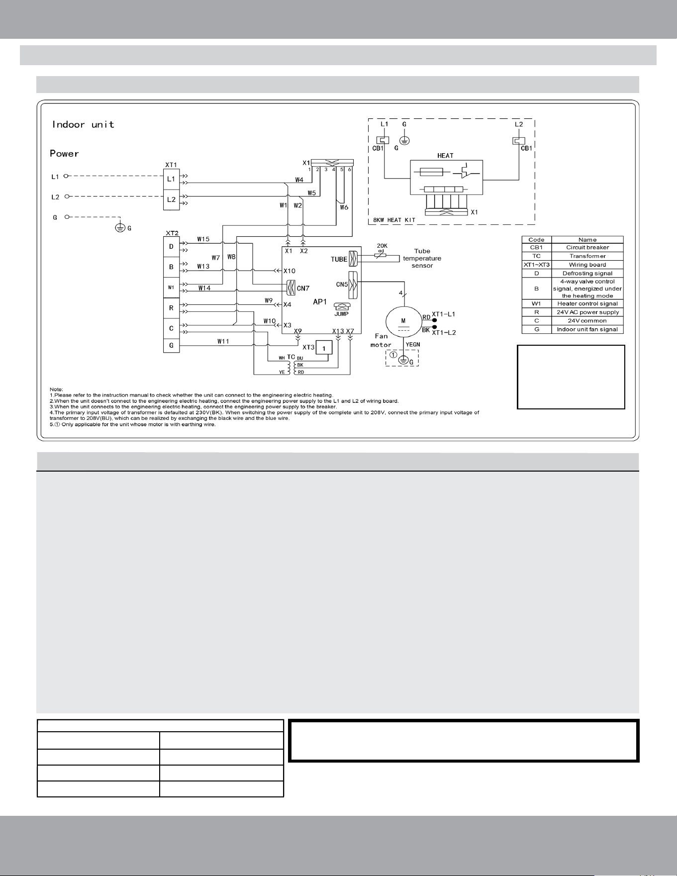
Wiring Diagram of MDUOC18024E/MDUI18036E (2-3 Ton with Electric Heat Kit)
NOTE: For wiring diagram of 4-5 ton units with
electric heater please refer to the next page.
Optional: Heat Kit Installation Instructions
1. Remove the upper access panel from the air handler.
2. Remove the cover plate inside the upper access panel of the air handler.
3. Slide the heat kit into the slot and secure element plate with previously removed screws.
4. Make sure to insert the supporting poles of the heat kit into the supporting hole of the air handler.
5. Connect the quick connection plug and fasten the loose wires by using wire ties.
6. Install the circuit breaker into the mounting rail, break out appropriate area of the plastic circuit
breaker cover on the access panel of the air handler.
7. a. When installing MHK05U, MHK08U, or MHK10U, connect the power from the Circuit Breaker
Panel to L1 and L2 of the circuit breaker included with the electric heat kit.
b. When connecting the electric heat kit to the air handler, use the Molex Plug Wiring Harness
from the electric heat kit and attach it to the Molex Plug Wiring Harness coming from air
handler’s PCB board.
c. The Molex Plug Connection will power the air handler, so you will not need a separate source of
incoming power for the air handler itself.
d. Please see the chart below for proper sizing of panel.
Circuit Breaker Size in Panel for Air Handler + Heat Kit
Combination
MDUI 24K/36K + MHK05U
MDUI 24K/36K + MHK08U
MDUI 24K/36K + MHK10U
60 Amps
45 Amps
30 Amps
Max Amperage
NOTE: A Heat Kit
Installation is NOT
required for the unit to
function properly. It is
intended for Emergency
Heat Purposes ONLY.
Electrical Connection
Page 27
mrcool.com
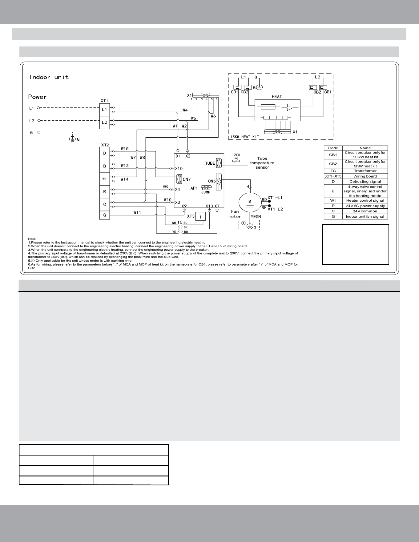
Unit Installation
Optional: Heat Kit Installation Instructions
1. Remove the upper access panel from the air handler.
2. Remove the cover plate inside the upper access panel of the air handler.
3. Slide the heat kit into the slot and secure element plate with previously removed screws.
4. Make sure to insert the supporting poles of the heat kit into the supporting hole of the air handler.
5. Connect the quick connection plug and fasten the loose wires by using wire ties.
6. Install the circuit breaker into the mounting rail, break out appropriate area of the plastic circuit
breaker cover on the access panel of the air handler.
7. a. When installing MHK15U or MHK20U, connect two separate lines of power from the
Circuit Breaker Panel to L1 and L2 of the two circuit breakers included with the electric heat kit.
b. When connecting the electric heat kit to the air handler, use the Molex Plug Wiring Harness
from the electric heat kit and attach it to the Molex Plug Wiring Harness coming from air
handler’s PCB board.
c. The Molex Plug Connection will power the air handler, so you will not need a separate source of
incoming power for the air handler itself.
d. Please see the chart below for proper sizing of panel.
Circuit Breaker Size in Panel for Air Handler + Heat Kit
Combination Max Amperage
MDUI 48K/60K+ MHK15U
60/30 Amps
60/60 Amps
MDUI 48K/60K + MHK20U
Wiring Diagram of MDUOC18048E/MDUI18060E (4-5 Ton with Electric Heat Kit)
NOTE: A Heat Kit
Installation is NOT
required for the unit to
function properly. It is
intended for Emergency
Heat Purposes ONLY.
Electrical Connection
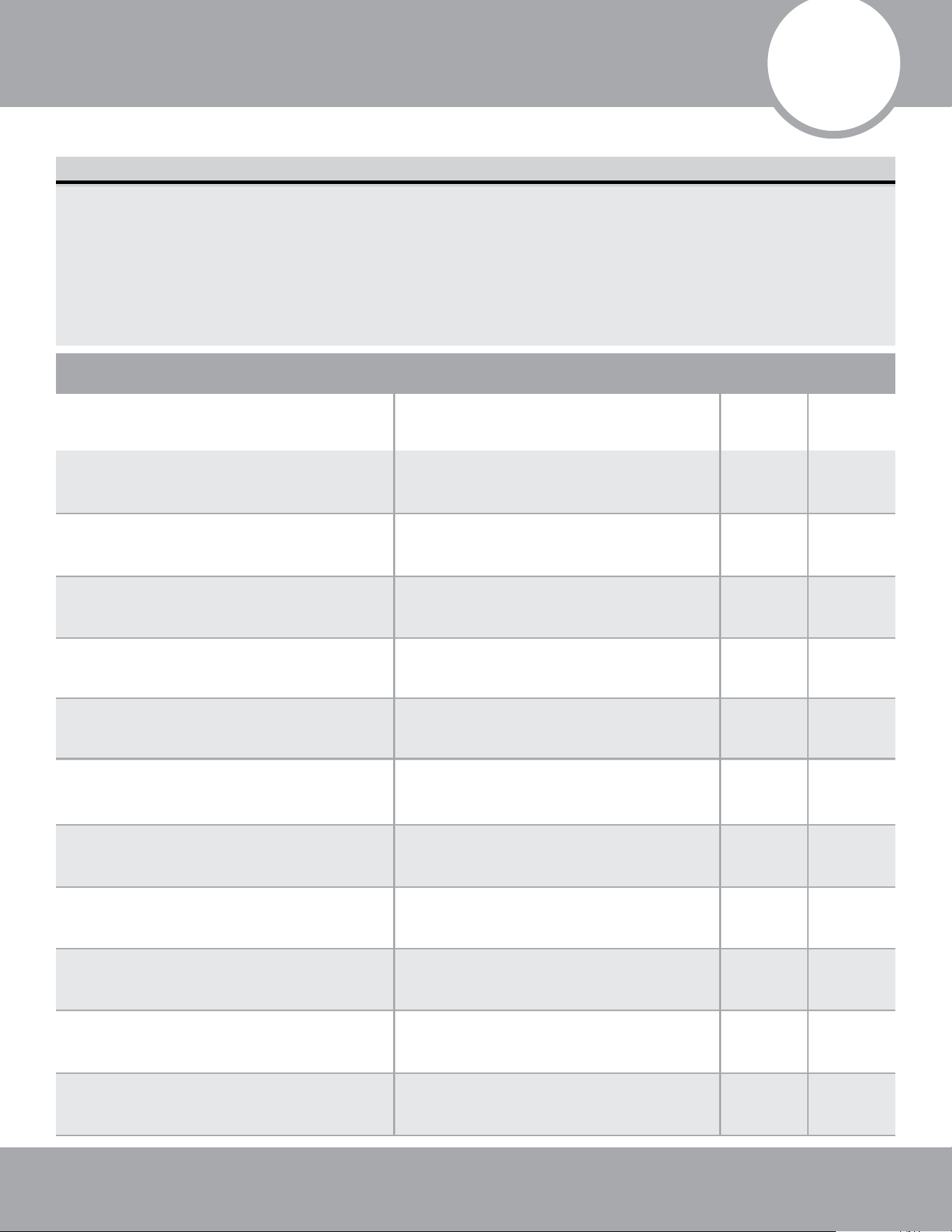
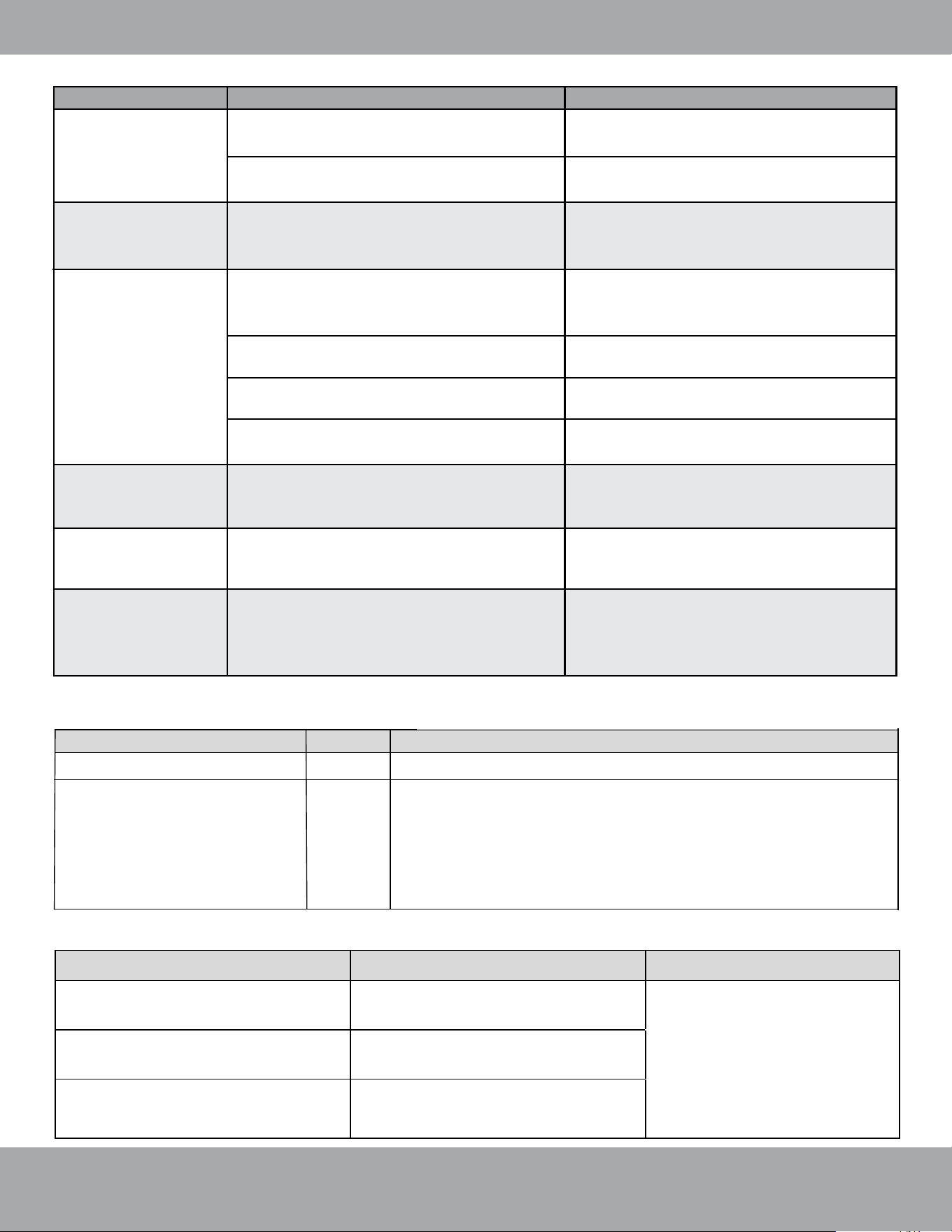
List of Checks to Perform Possible Malfunctions PASS/FAIL
Before Test Run
Only perform test run AFTER you have completed the following steps:
• Electrical Safety Checks – Confirm that the electrical system is safe and operating properly.
• Gas Leak Checks – Check all refrigerant piping connections/valves and confirm that the system
is not leaking.
• Confirm that gas and liquid (high and low pressure) valves are fully open.
3
Post Installation Checks
Page 28
mrcool.com
Is the main body installed securely?
The unit could fall down, vibrate or
produce noise
Did you conduct a water leakage test? Cooling capacity could become
inadequate
Is the unit well insulated from heat?
Condensate/water droplets may
occur
Does water drain properly from drain
hose?
Condensate/water droplets may
occur
Is the voltage consistent with the
specifications stated on the nameplate?
The unit may fail or its components
could get burned.
Are the wires, piping, and valves
installed correctly?
The unit could fail or its components
may ignite.
Has the unit been safely grounded?
Risk of electrical leakage.
Do the wire specifications comply with
the requirements?
The unit could fail or its components
may ignite.
Are there any obstacles blocking the air
inlet or outlets of the units?
Cooling capacity may become
unsatisfactory.
Have you recorded the length of
refrigerant pipe and the refrigerant
charge amount?
The refrigerant charging amount
cannot be controlled.
Is the panel mounted securely? It could cause an air leak, vibration, and
noise.
Are there any cracks in the air return or
supply pipe?
It could cause an air leak, vibration, and
condensation.

Page 29
mrcool.com
Post Installation Checks
Preparation Before Connecting The Power:
DO NOT connect power unless installation is complete.
1. Verify the control circuit is correct and all the wires are firmly and securely connected.
2. Ensure valves on the vapor and liquid refrigerant lines are completely opened.
3. Remove any scattered objects or debris, especially metal filings, thrum, and clippings.
4. Ensure the unit’s appearance and piping system have not been damaged during transportation or handling.
5. Check for any loose terminals and ensure the phases are correct.
Operation After Connecting The Power:
1. If all the above steps are complete, power on the unit.
2. Verify the unit functions normally under several of its different operating modes.
3. If there are any loud and/or abnormal sounds, turn off the unit and contact MRCOOL
®
Tech Support, at
(270) 366-0457, immediately.
Test Run
Page 30
mrcool.com
Outdoor Unit Installation
Maintenance
4
4
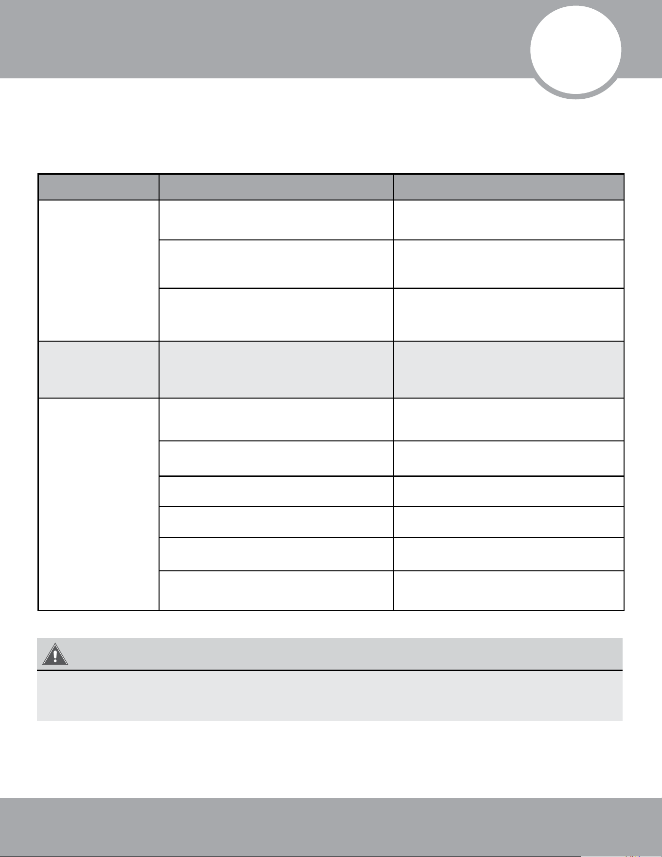
Troubleshooting
(1) If your air conditioner fails to function normally, check the following items before conducting
maintenance:
NOTICE
Check the above items and take appropriate corrective measures. If the unit continues to function
improperly, immediately disconnect power and contact the MRCOOL
®
technical department, at (270)
366 - 0457, or your installation dealer.
Problem Cause Corrective Measure
The unit will not
activate.
Abnormal cooling
or heating.
The unit operates
but stops
immediately.
The unit is not connected to a
power supply.
Low voltage.
Fuse broken or circuit breaker trips.
Connect it to the power supply.
Check the circuit voltage is
within specified range.
Replace fuse or reconnect circuit
breaker.
Remove obstacles.
Adjust thermostat temperature
setting.
Close the door or windows.
Draw curtain or louver.
Reduce other heat sources.
Clean the filter.
Air inlet and outlet of the units are
blocked.
Air inlet and outlet of the units are
blocked.
Filter screen is blocked by dirt.
Other heat sources in the room.
Doors or windows are opened.
Rooms exposed to excessive direct
sunshine.
Improper temperature setting.
Clear any obstacles and ensure the
area remains well ventilated.
Page 31
mrcool.com
Troubleshooting
Problem Time of Occurrence Cause
Mist comes from
the unit.
Unit does not run.
The unit
generates noise.
The unit emits
odor.
Indoor unit still
runs after being
switched off.
Dust comes
from the unit.
During operation.
When power is turned on.
When unit is started immediately
after it is just turned off.
There is a continuous sound when
cooling.
The unit makes a sound when unit
starts or stops.
Slight cracking sound is heard when
unit is turned on.
Electronic expansion valve
initialization can cause this noise
temporarily.
There is slight and continuous sound
when unit is running or after running.
When unit is run after an extended
period of not being operated.
After every indoor unit receives a
"stop" signal, the fan will continue
running.
If the unit is running under high
humidity, the wet air in the room
will be quickly cooled down.
Overload protection switch causes
a 3 minute delay.
Start up could be delayed
up to 1 minute.
Gas refrigerant flow can cause a
slight noise.
Gas refrigerant flow can cause a
slight noise.
The drainage system can cause
this noise during operation.
Dust has settled inside the indoor
unit and is being dispersed from the
system.
During operation.
Smells from the operating
environment may be pulled through
the air handler.
Indoor fan can be set as “ON” or
“AUTO” mode. Under “ON” mode,
indoor fan will keep running after
switching off the unit.
(2) The following situations are not operation failures.
There are LED indicators on the main board of the indoor unit, which are used to display the
operating status and malfunction information of the unit.
Power Indicator
Red
Indoor unit main board is powered on, Power Indicator is on.
Running Indicator
Green
-After detecting the signal that the indoor fan is turned on,
the running indicator light is on.
-After detecting the signal the indoor fan is turned off, the
running indicator light is off.
-When detecting a system failure, the running indicator
light flashes.
Different running indicator flashing light means different system failure.
Lorem ipsum
Flash means that the light is
on 0.5S, and then light out
0.5S
Light will go out for 3 seconds and
then flash once.
Light will go out for 3 seconds and
then flash twice.
Light will go out for 3 seconds and
then flash four times.
Indoor tube temperature
sensor failure
Indoor fan failure
Indoor Jumper cap failure
LED indicator
Color
Function
Malfunction
Running Indicator status
Remark

Page 32
mrcool.com
Troubleshooting
WARNING
• When abnormalities occur, stop the unit immediately and disconnect power. Contact MRCOOL
®
Tech Support, at (270) 366-0457. If the unit continues to run abnormally, it may damage the
unit and cause an electric shock or a fire hazard.
DO NOT attempt repairs to the appliance yourself. Improper repair and maintenance can
create electric shock and fire hazards. Please contact MRCOOL
®
Tech Support, at
(270) 366-0457 for further guidance or a qualified professional for repairs.

5
Page 33
Page 30
mrcool.com
Maintenance and Care
Drain Pipe
Notice Before Seasonal Use
Regular checks, maintenance, and care should be performed by professional personnel, which will
extend the lifespan of the unit.
Regularly check the drain pipe for clogs in order to ensure smooth condensate drainage.
Purchase replacement parts from a local appointed service center or dealer if necessary.
1. Check the inlet/outlet of the indoor unit and ensure it is not clogged.
2. Check the ground wire and ensure it is securely connected.
3. Check if the filter screen has been installed correctly.
4. Check if the unit is firmly and securely installed.
5. If you should notice something abnormal, please contact the local appointed service center.
Maintenance After Seasonal Use
Parts Replacement
If the air-conditioning unit you have purchased has any quality problem, or you have any inquiry regarding the
product, please contact the MRCOOL
®
Tech Support, at (270) 366-0457.
Warranty should meet the following requirements:
1. Initial startup and first run of the unit should be performed by professional personnel from a factory
appointed service center.
2. Only factory-manufactured or OEM accessories can be used on the machine.
3. All the instructions listed in this manual should be followed completely.
4. The warranty will be automatically voided if the above requirements are not met.
After-Sales Service
1. Cut off the main power supply of the unit.
2. Clean the filter screen of the indoor unit.
3. Clean the dust and debris from the indoor unit.
4. In the event of rusting, use anti-rust paint to stop it from spreading.
Page 34
mrcool.com
Refrigerant Piping Connection
Special notice
This appliance contains refrigerant and other potentially hazardous materials. When disposing of this appliance,
the law requires special collection and treatment.
DO NOT dispose of this product as household waste or unsorted municipal waste.
When disposing of this appliance, you have the following options:
• Dispose of the appliance at a designated municipal electronic waste collection facility.
• When buying a new appliance, the retailer will receive the old appliance free of charge.
• The manufacturer will receive the old appliance free of charge.
• Sell the appliance to certified scrap metal dealers.
Disposing of this appliance in the forest or other natural surroundings endangers your health and is
bad for the environment. Hazardous substances may leak into the ground water and enter the food
chain.
6
EU Disposal Guidelines

Universal
®
Series
The design and specifications of this product and/or manual are subject to change without prior notice.
Consult with the sales agency or manufacturer for details.
Copyright © 2021 MRCOOL, LLC.
ELECTRICIAN and/or HVAC TECHNICIAN:
LICENSE #:
INSTALLATION DATE:
INSTALLATION LOCATION:
SERIAL NUMBER: