MODELS:
Read this manual carefully before installation and keep it where
the operator can easily nd it for future reference.
Due to updates and constantly improving performance, the
information and instructions within this manual are subject to
change without notice.
Version Date: March 10, 2025
Please visit www.mrcool.com/documentation
to ensure you have the latest version of this manual.
This product utilizes R-454B refrigerant
DIY
®
Series
Single-Zone
Mini-Split System
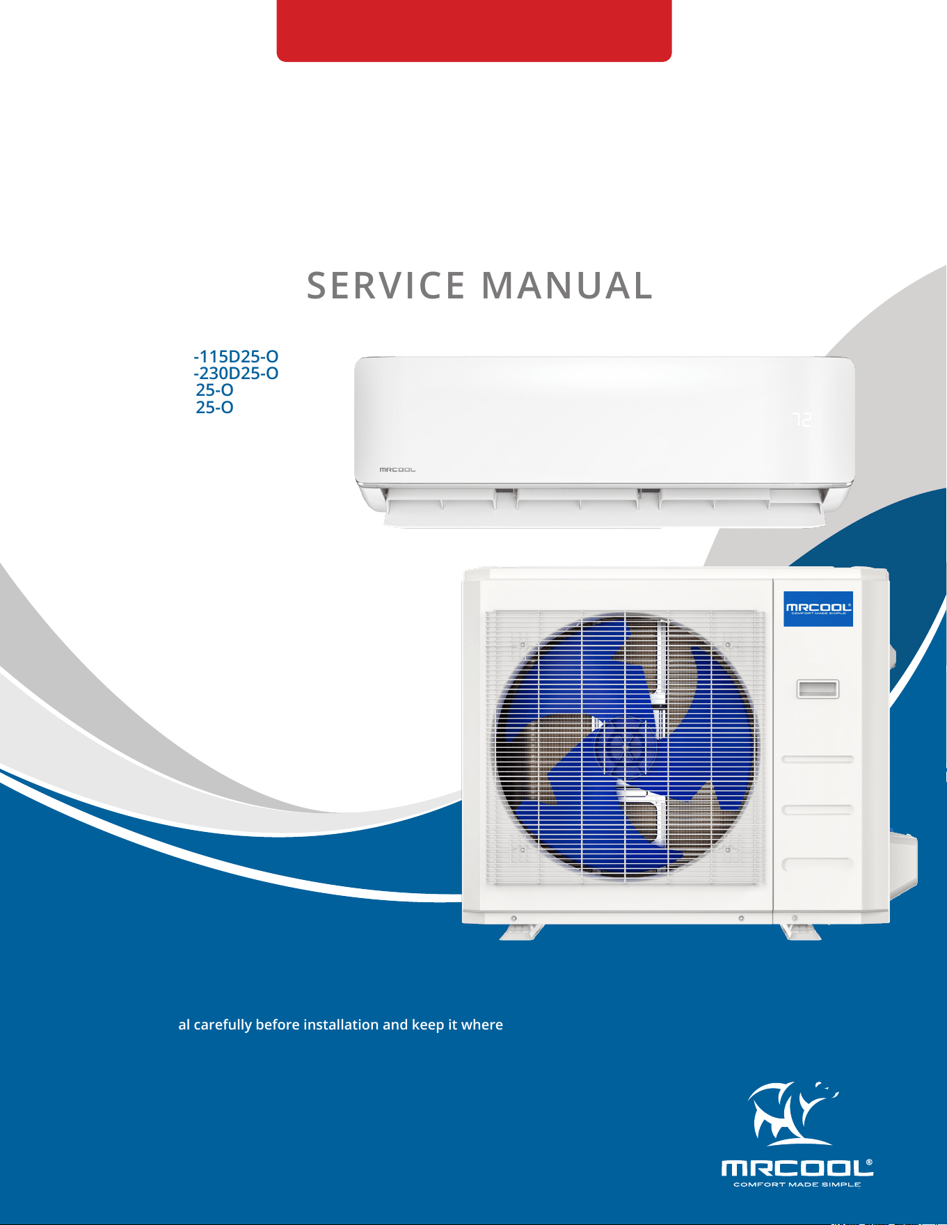
SERVICE MANUAL
DIY-*-HP-WMAH-115D25-O
DIY-*-HP-WMAH-230D25-O
DIY-*-HP-C-115D25-O
DIY-*-HP-C-230D25-O

mrcool.com1
CONTENTS
SYSTEM OVERVIEW ........................................................................................................... 2
1.1 Model Reference .................................................................................................. 2
1.2 Pipe Length and Drop Height ............................................................................. 2
1.3 Air Velocity and Temperature Distributions .................................................... 3
1.4 Refrigerant Cycle Diagrams .............................................................................. 13
1.5 Electrical Wiring Diagrams ............................................................................... 15
PRODUCT FEATURES ...................................................................................................... 27
2.1 Display Functions .............................................................................................. 27
2.2 Safety Features ................................................................................................. 27
2.3 Basic Functions .................................................................................................. 28
REFRIGERANT CHARGE ................................................................................................... 34
3.1 Refrigerant Recharge ........................................................................................ 34
TROUBLESHOOTING ....................................................................................................... 35
4.1 Safety Caution .................................................................................................... 35
4.2 Error Display (Indoor Unit) ............................................................................... 36
4.3 Error Display (Outdoor Unit with Auxiliary Board ......................................... 37
4.4 Outdoor Unit Point Check Function ................................................................ 38
4.5 Error Diagnosis Without Error Code ................................................................ 45
4.6 Quick Maintenance by Error Code .................................................................. 52
4.7 Troubleshooting by Error Code ....................................................................... 54
4.8 Check Procedures .............................................................................................. 83
Temperature Sensor Resistance Table ....................................................................... 90
5.1 Temperature Sensor Resistance Value Table for TP (°C-K) ......................... 90
System Pressure Table ................................................................................................... 92
6.1 System Pressure Table-R545B.......................................................................... 92
1
2
3
4
5
Contents
6
mrcool.com 2 2
SYSTEM OVERVIEW
1
1.1 Model Reference
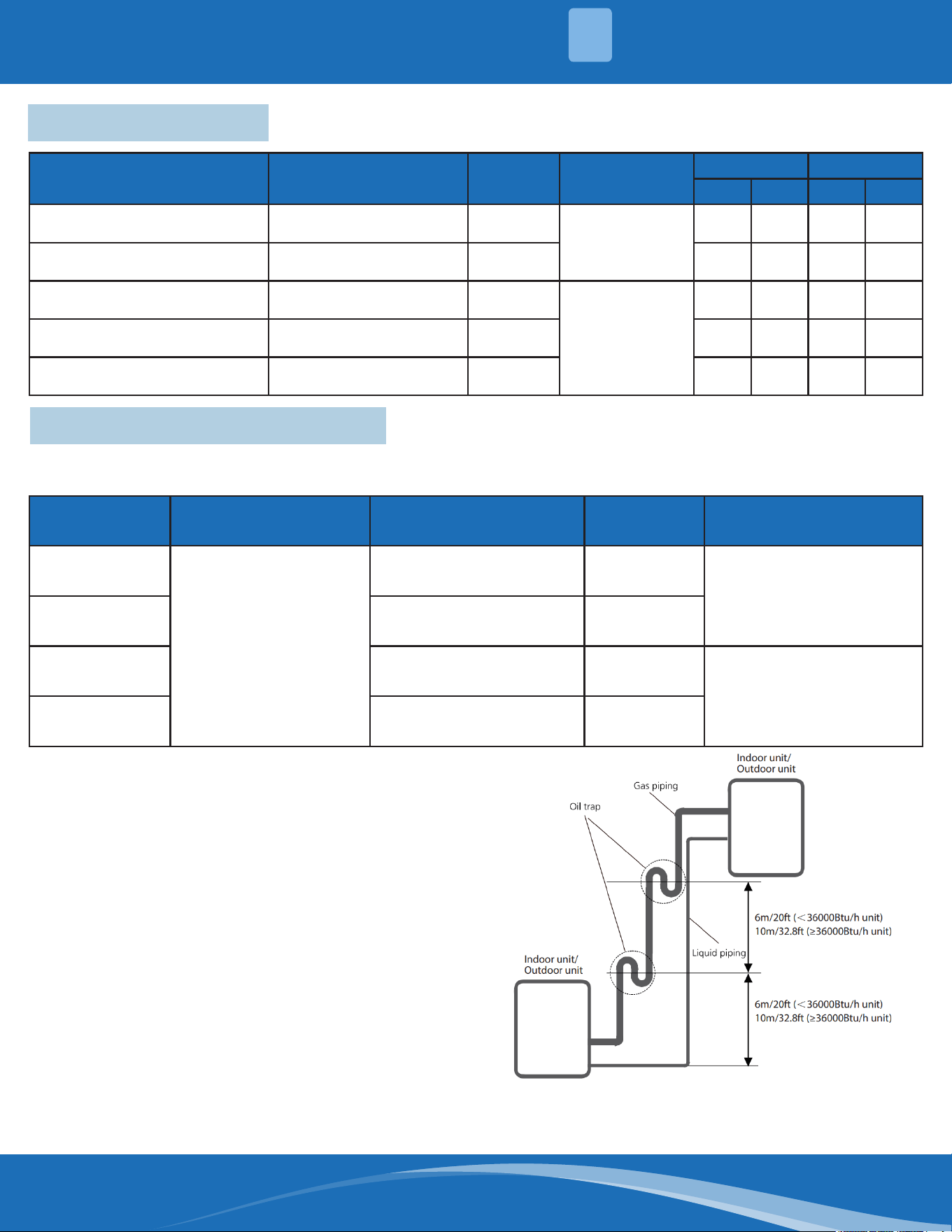
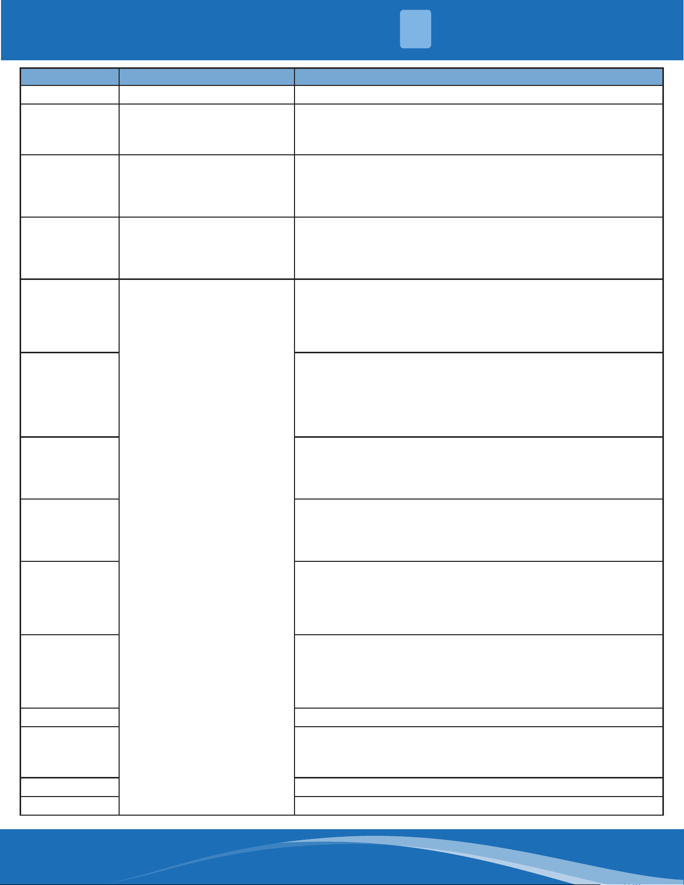
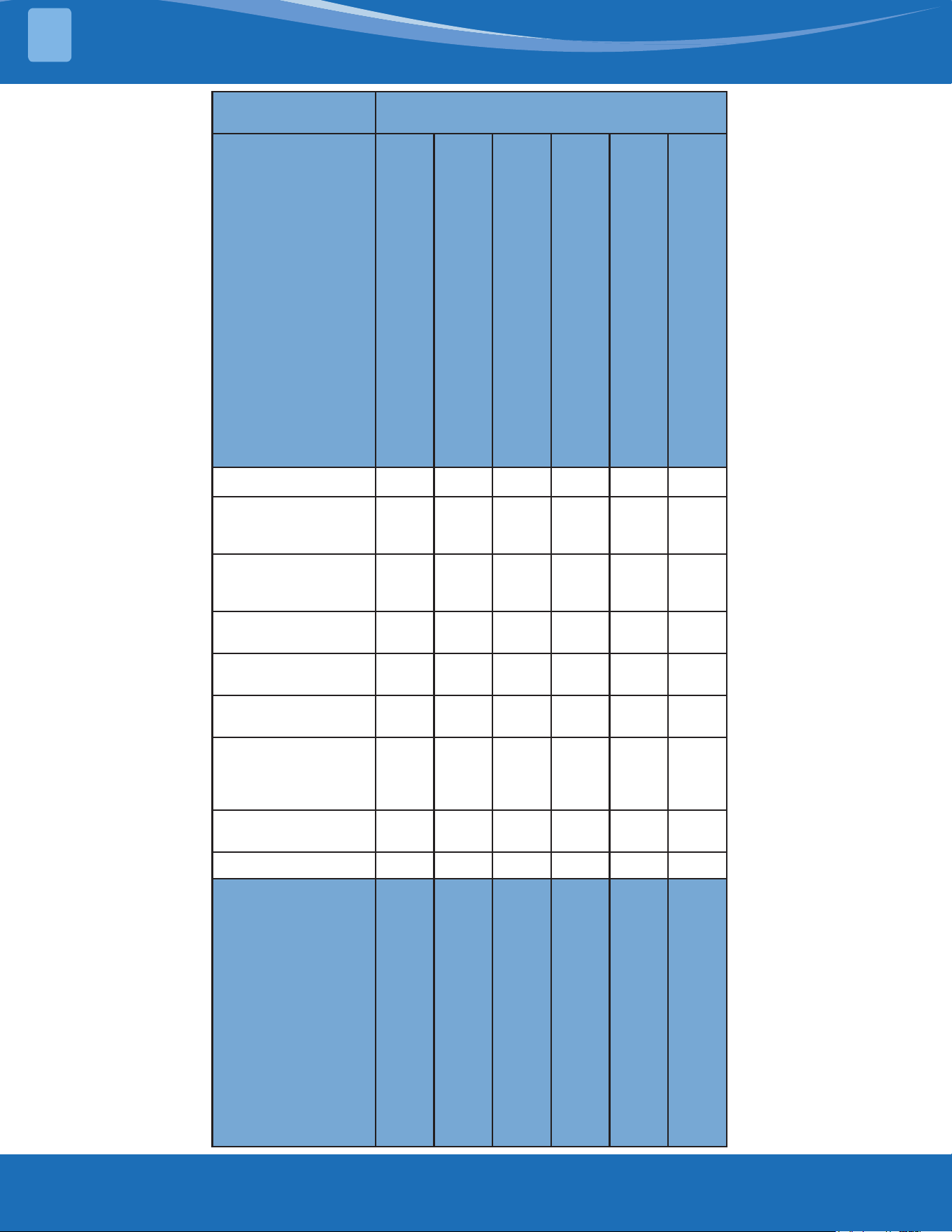
1.2 Pipe Length and Drop Height
Capacity
(Btu/h)
Standard Length Max. Pipe Length
Max
Elevation
Additional Refrigerant
9k/12k
24.6ft (7.5m)
82ft (25m) 49.2ft (15m)
0.16oz/ft (15g/m)
18K 98.4ft (30m) 65.6ft (20m)
24K 164ft (50m) 82ft (25m)
0.32oz/ft (30g/m)
36K 213ft (65m) 98.4ft (30m)
The length and elevation of refrigerant lines are shown in the table below. If the pipe length exceeds
standard pipe length, Additional refrigerant should be charged to ensure nominal cooling/heating capacity.
If oil ows back into the compressor this might
cause liquid compression or deterioration of
oil return. Oil traps in the rising gas pipe can
prevent this.
• An oil trap should be installed every 20ft (6m)
of vertical suction line (< 36000Btu/h unit).
• An oil trap should be installed every 32.8ft
(10m) of vertical suction line (≥36000Btu/h
unit).
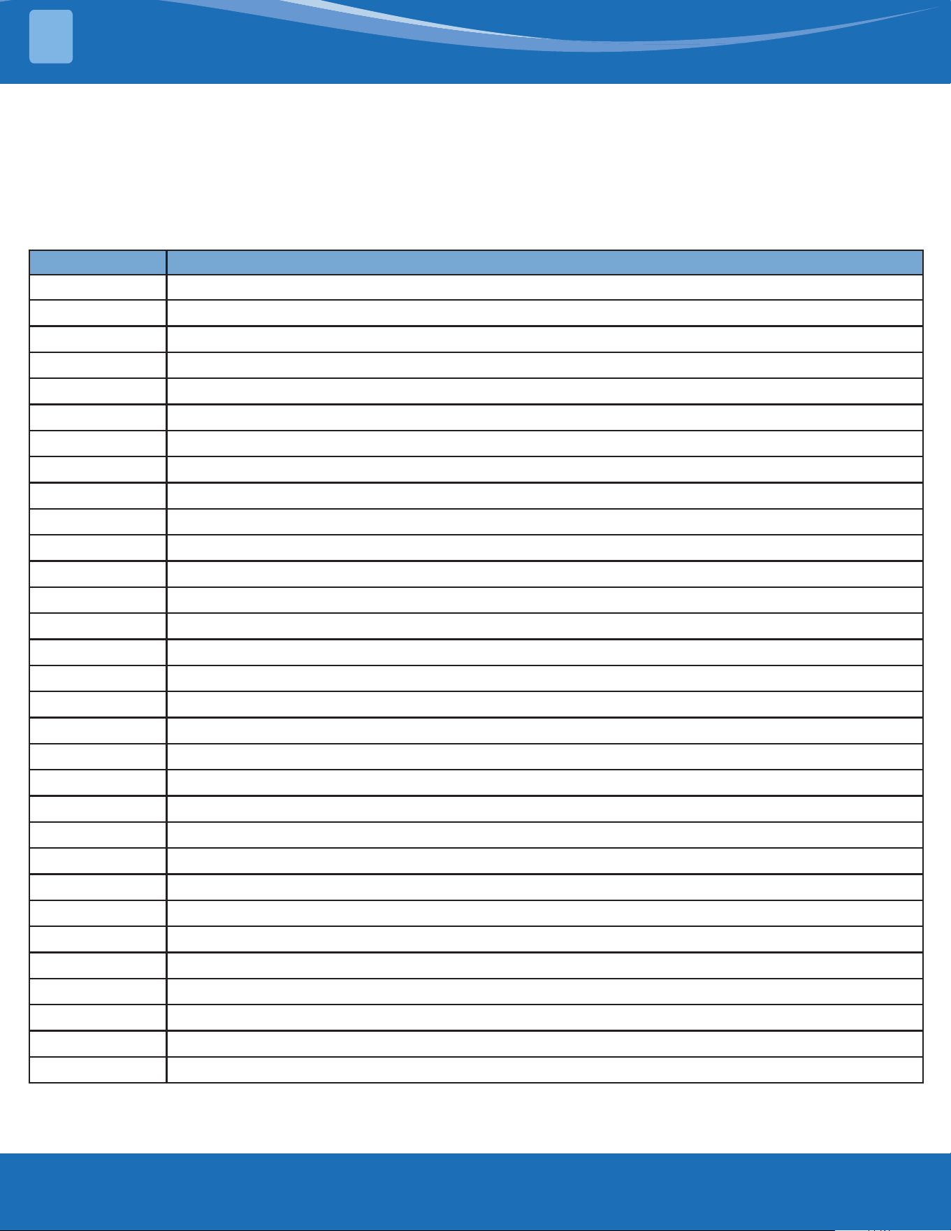
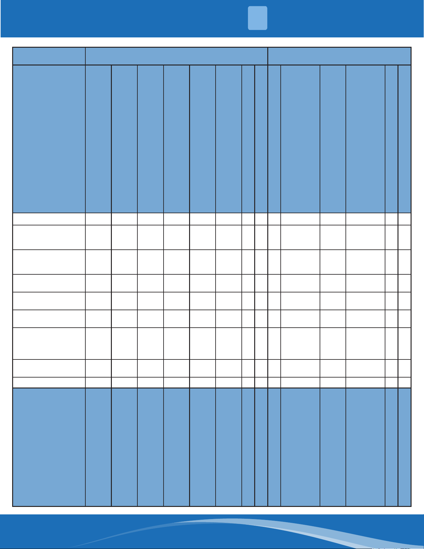
Indoor Unit Model Outdoor Unit Model
Capacity
(Btu/h)
Power Supply
Amperage Wire Size
Min. Max. Min. Max.
DIY-09-HP-WMAH-115D25-O DIY-09-HP-C-115D25-O 9K
115V~, 60Hz, 1
Phase
18 20 12 12
DIY-12-HP-WMAH-115D25-O DIY-12-HP-C-115D25-O 12K 18 20 12 12
DIY-18-HP-WMAH-230D25-O DIY-18-HP-C-230D25-O 18K
208/230V~,
60Hz, 1 Phase
18 20 12 12
DIY-24-HP-WMAH-230D25-O DIY-24-HP-C-230D25-O 24K 24 25 10 10
DIY-36-HP-WMAH-230D25-O DIY-36-HP-C-230D25-O 36K 33 35 10 8
mrcool.com3
SYSTEM OVERVIEW
1
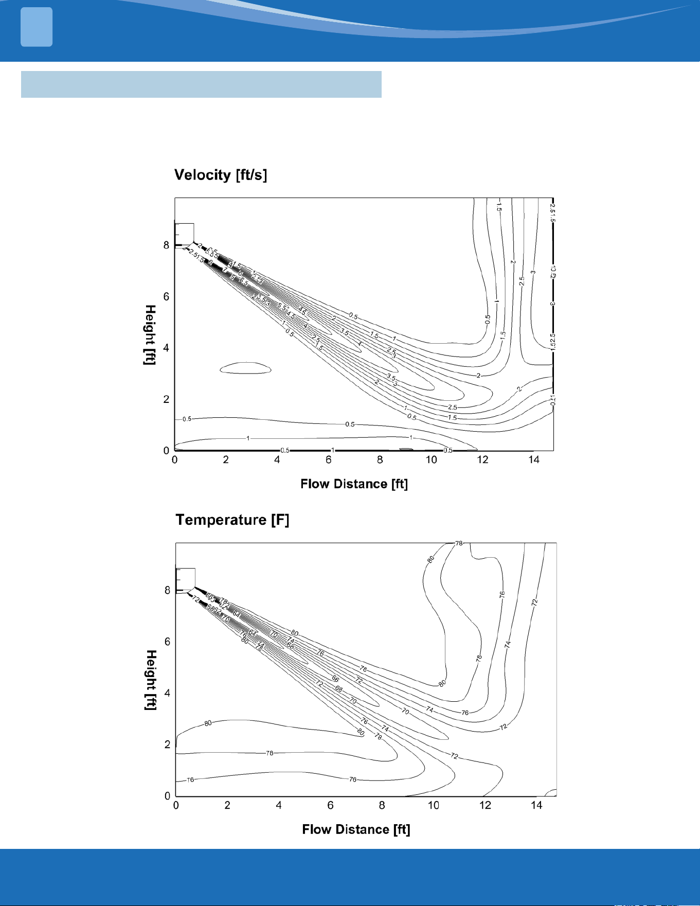
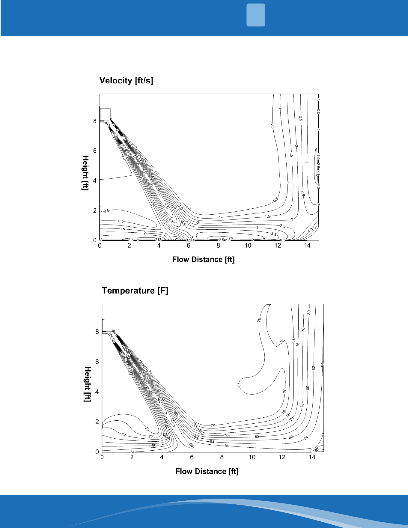
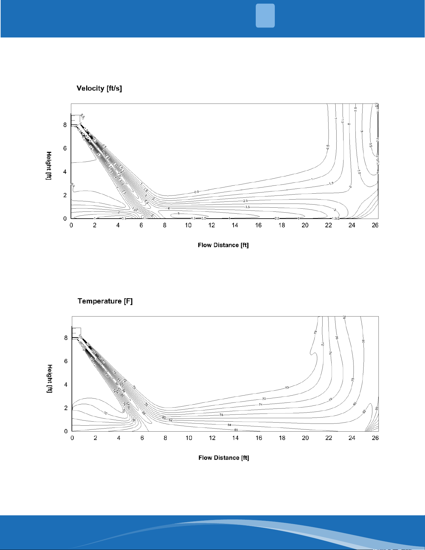
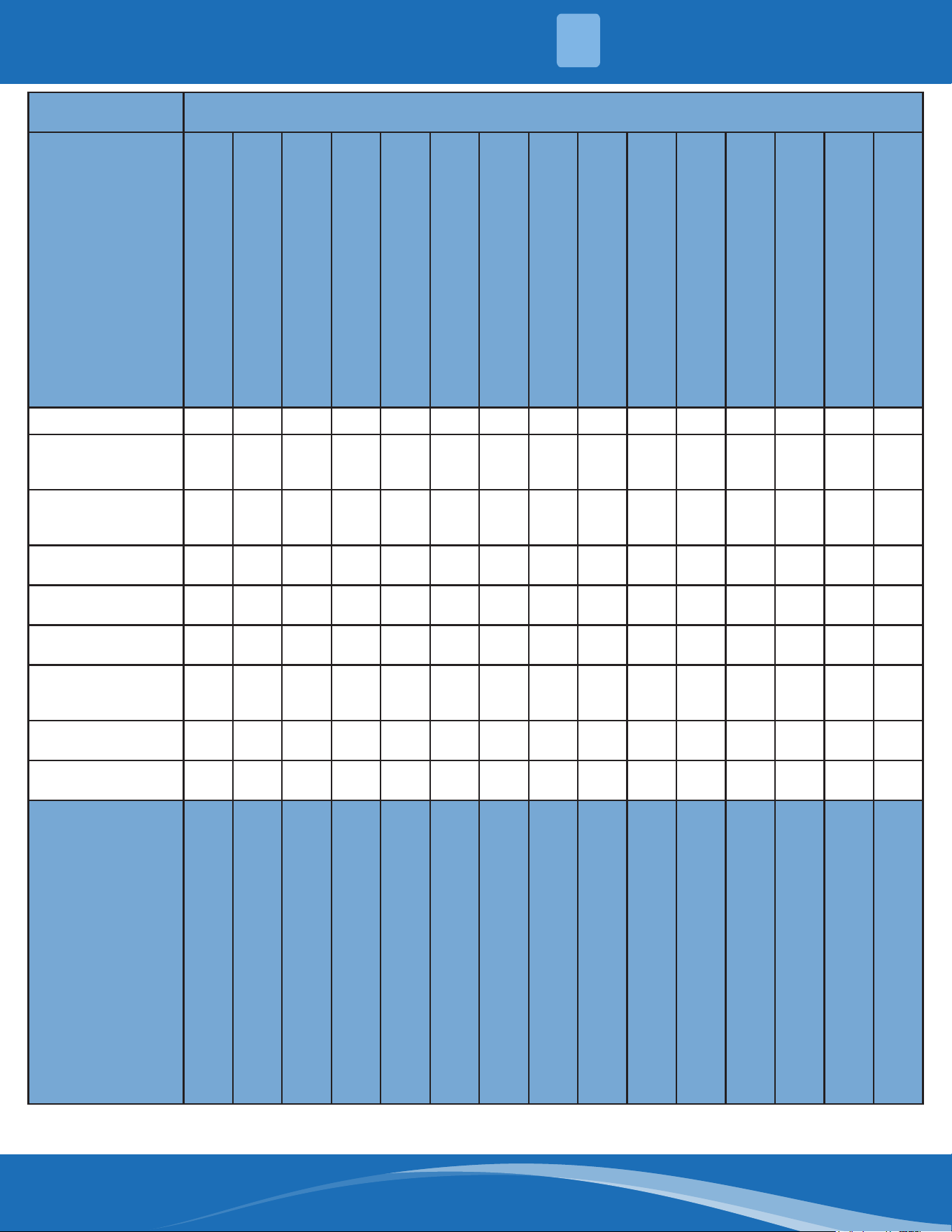
1.3 Air Velocity and Temperature Distributions
DIY-09-HP-WMAH-115D25-O: Cooling (Indoor: 80.6°F/27°C Outdoor: 95°F/35°C)
Discharge angle 58°
Airow Velocity Distributions
Temperature Distributions
mrcool.com 4
4
SYSTEM OVERVIEW
1
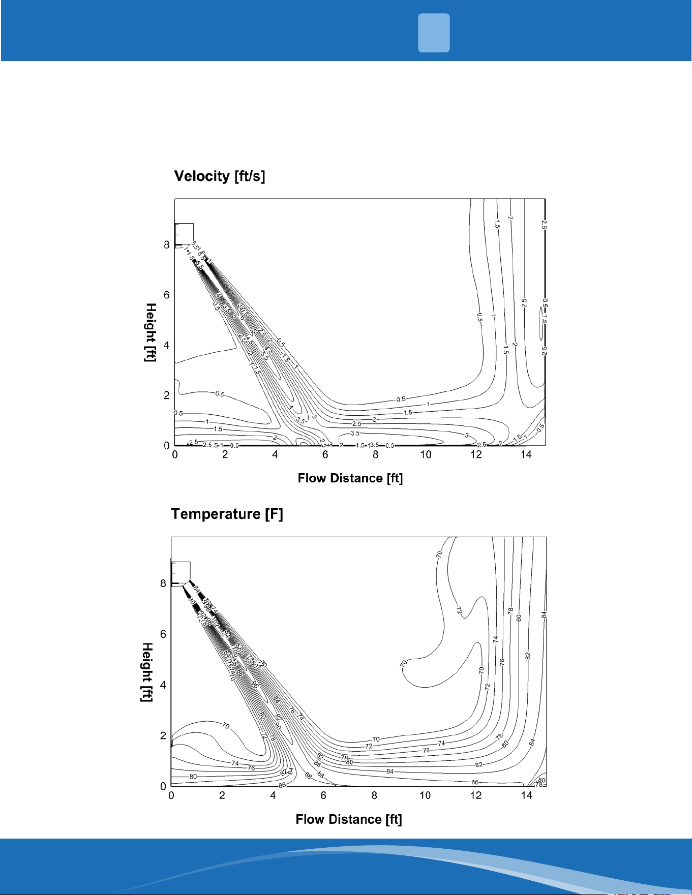
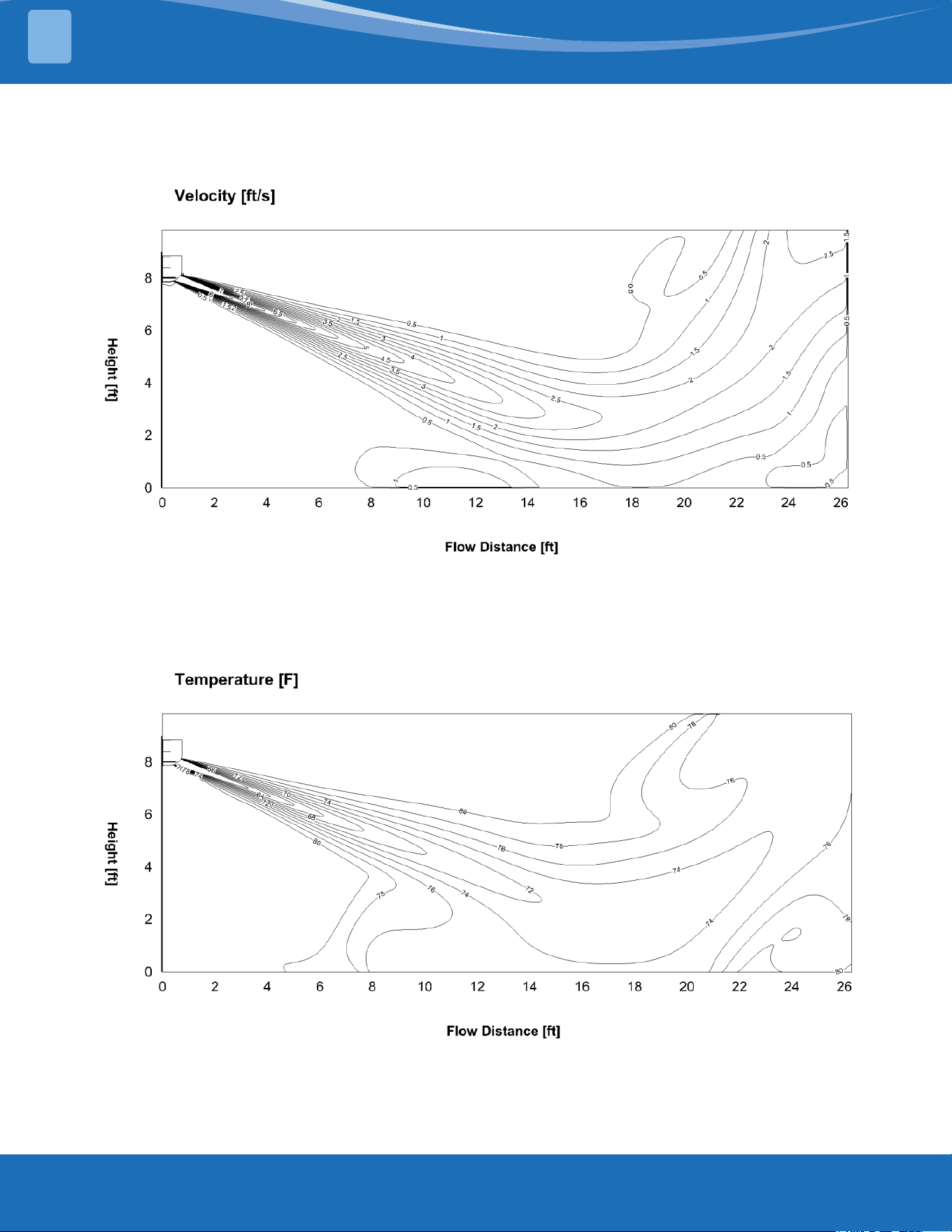
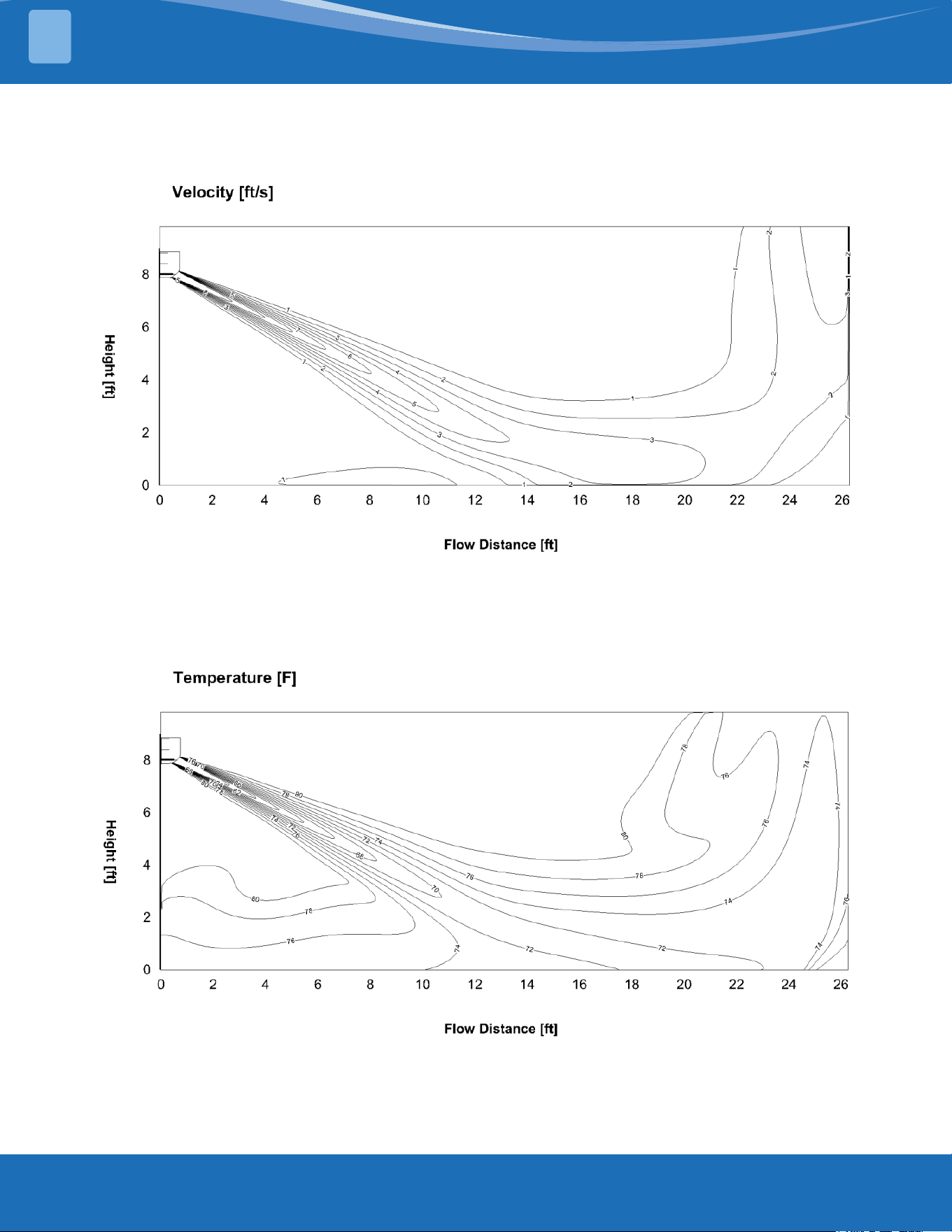
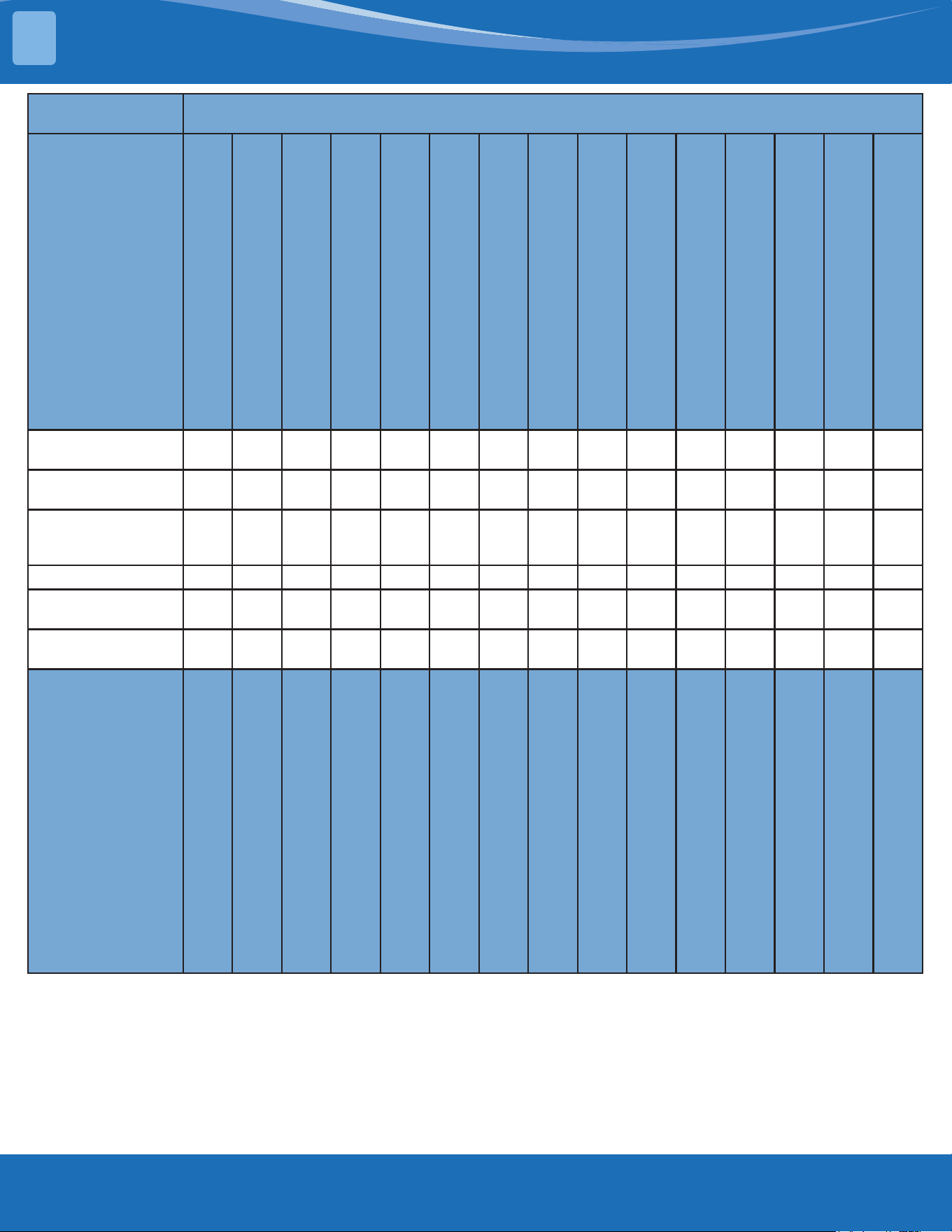
DIY-09-HP-WMAH-115D25-O: Heating (Indoor: 68°F/20°C Outdoor: 44.6°F/7°C)
Discharge angle 90°
Airow Velocity Distributions
Temperature Distributions
mrcool.com5
SYSTEM OVERVIEW
1
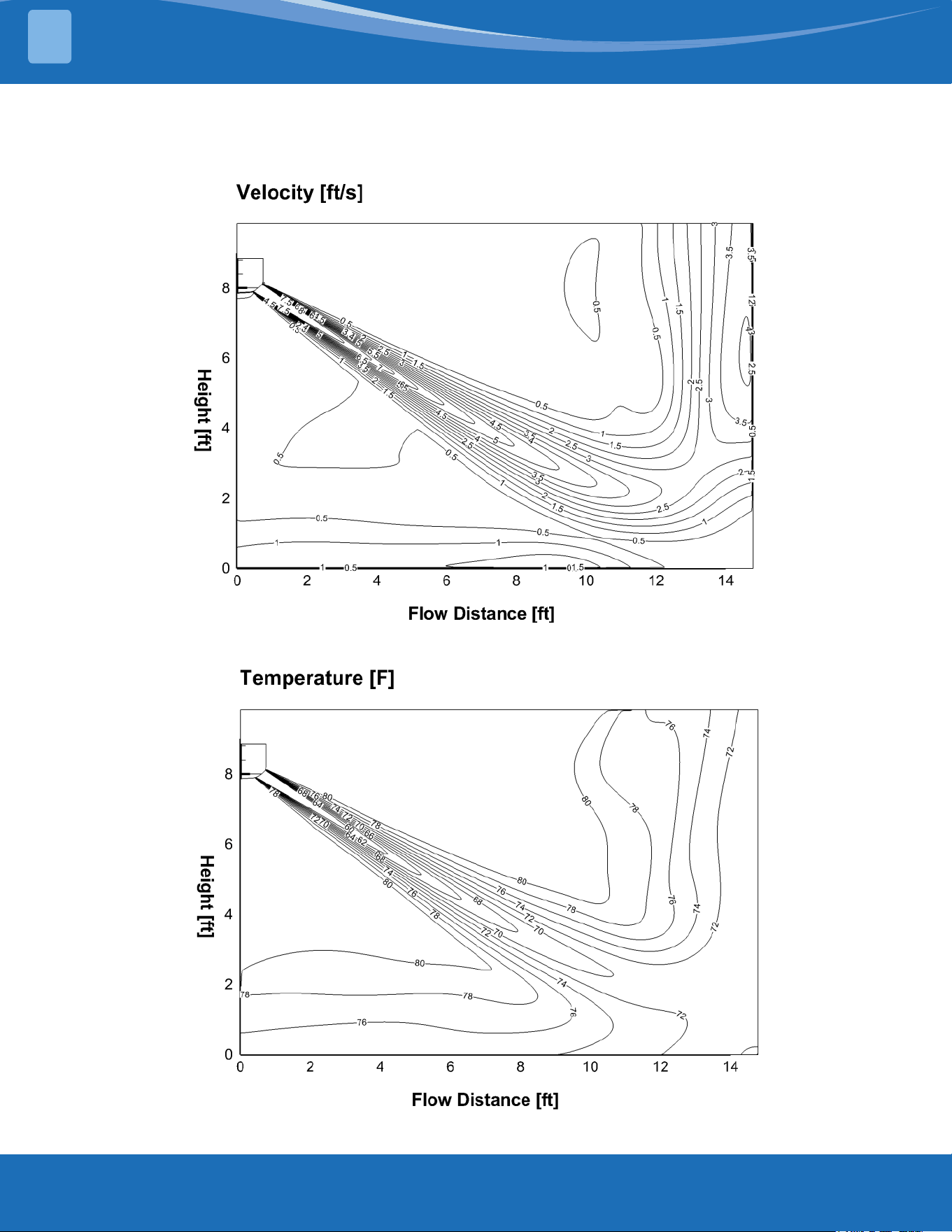
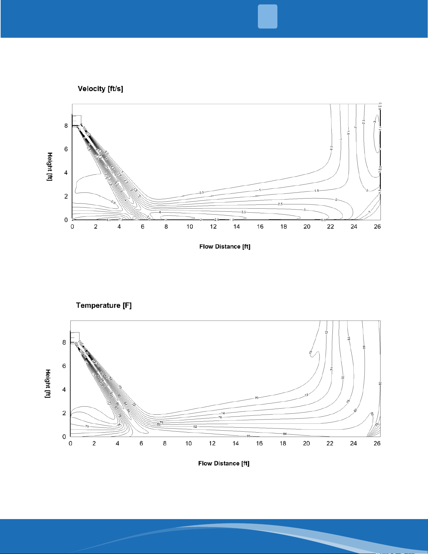
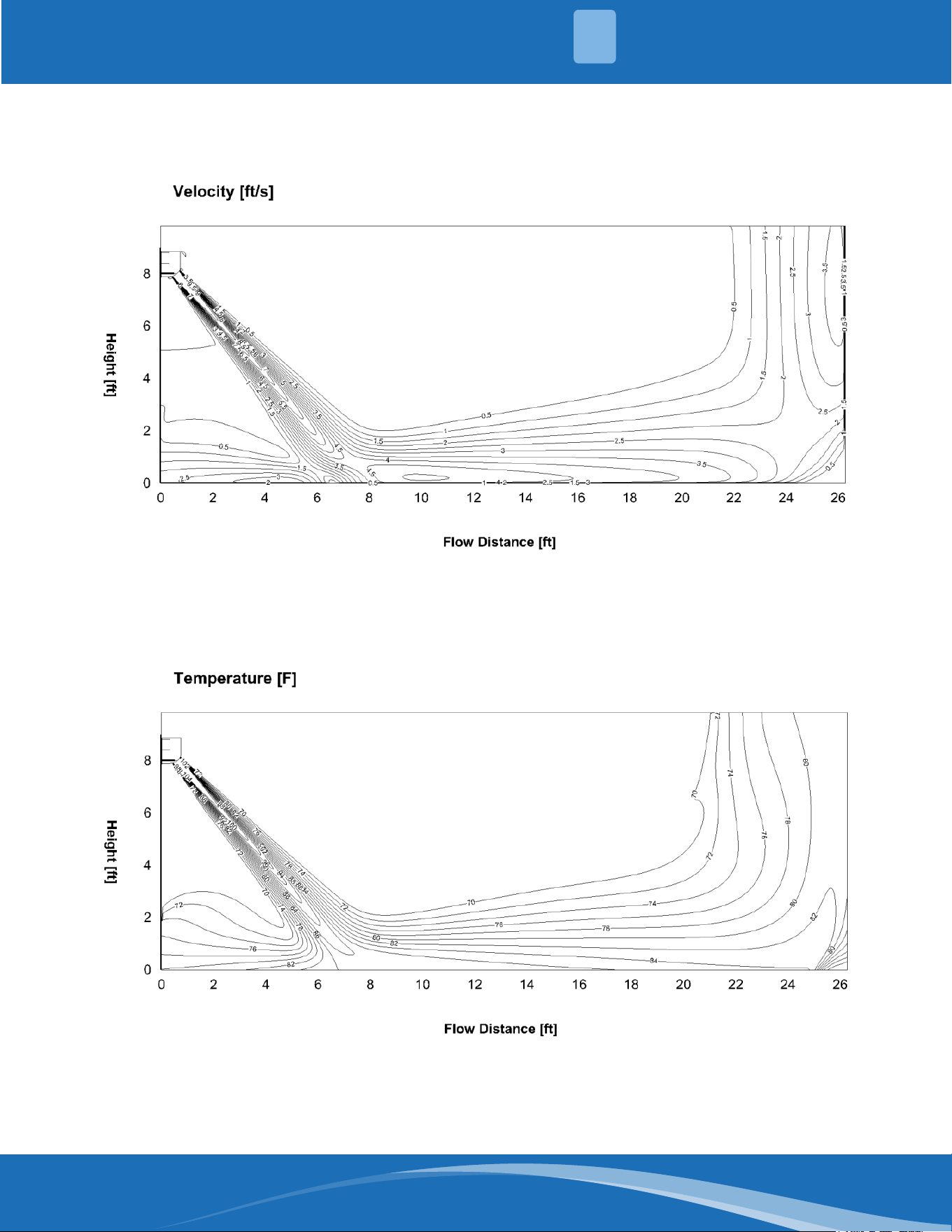
DIY-12-HP-WMAH-115D25-O: Cooling (Indoor: 80.6°F/27°C Outdoor: 95°F/35°C)
Discharge angle 58°
Airow Velocity Distributions
Temperature Distributions
mrcool.com 6
6
SYSTEM OVERVIEW
1
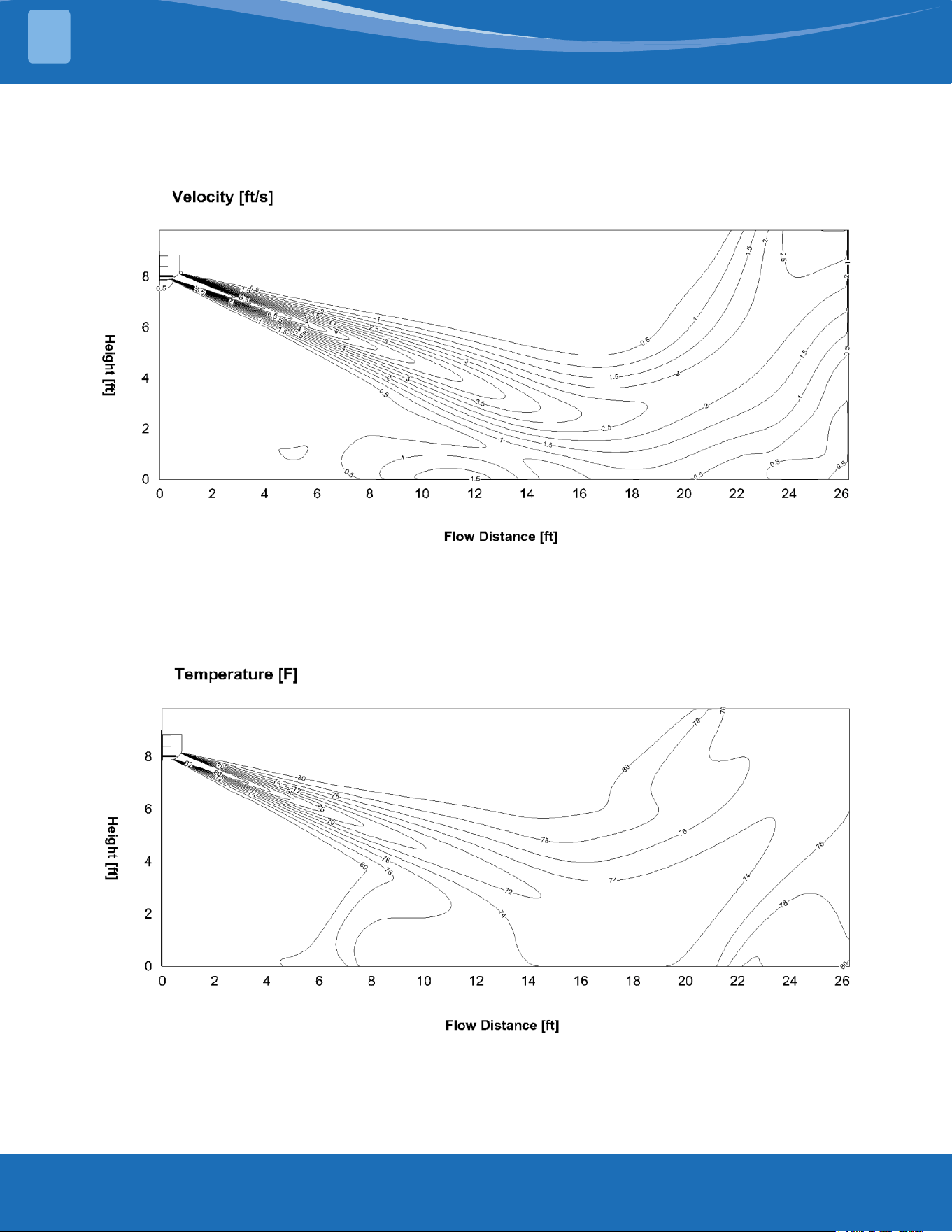
DIY-12-HP-WMAH-115D25-O: Heating (Indoor: 68°F/20°C Outdoor: 44.6°F/7°C)
Discharge angle 90°
Airow Velocity Distributions
Temperature Distributions
mrcool.com7
SYSTEM OVERVIEW
1
DIY-18-HP-WMAH-230D25-O: Cooling (Indoor: 80.6°F/27°C Outdoor: 95°F/35°C)
Discharge angle 50°
Airow Velocity Distributions
Temperature Distributions
mrcool.com 8
8
SYSTEM OVERVIEW
1
DIY-18-HP-WMAH-230D25-O: Heating (Indoor: 68°F/20°C Outdoor: 44.6°F/7°C)
Discharge angle 84°
Airow Velocity Distributions
Temperature Distributions
mrcool.com9
SYSTEM OVERVIEW
1
DIY-24-HP-WMAH-230D25-O: Cooling (Indoor: 80.6°F/27°C Outdoor: 95°F/35°C)
Discharge angle 50°
Airow Velocity Distributions
Temperature Distributions
mrcool.com 10
10
SYSTEM OVERVIEW
1
DIY-24-HP-WMAH-230D25-O: Heating (Indoor: 68°F/20°C Outdoor: 44.6°F/7°C)
Discharge angle 77°
Airow Velocity Distributions
Temperature Distributions
mrcool.com11
SYSTEM OVERVIEW
1
DIY-36-HP-WMAH-230D25-O: Cooling (Indoor: 80.6°F/27°C Outdoor: 95°F/35°C)
Discharge angle 55°
Airow Velocity Distributions
Temperature Distributions
mrcool.com 12
12
SYSTEM OVERVIEW
1
DIY-36-HP-WMAH-230D25-O: Heating (Indoor: 68°F/20°C Outdoor: 44.6°F/7°C)
Discharge angle 75°
Airow Velocity Distributions
Temperature Distributions
mrcool.com13
SYSTEM OVERVIEW
1
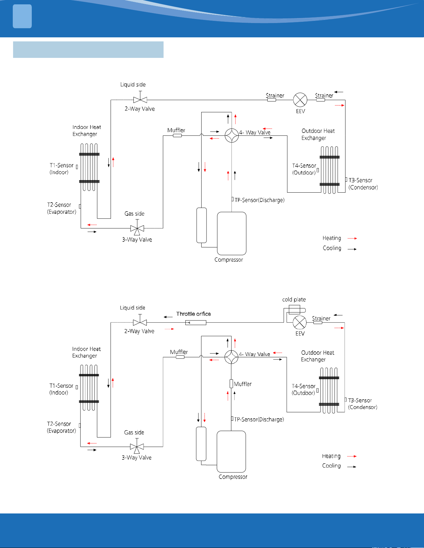
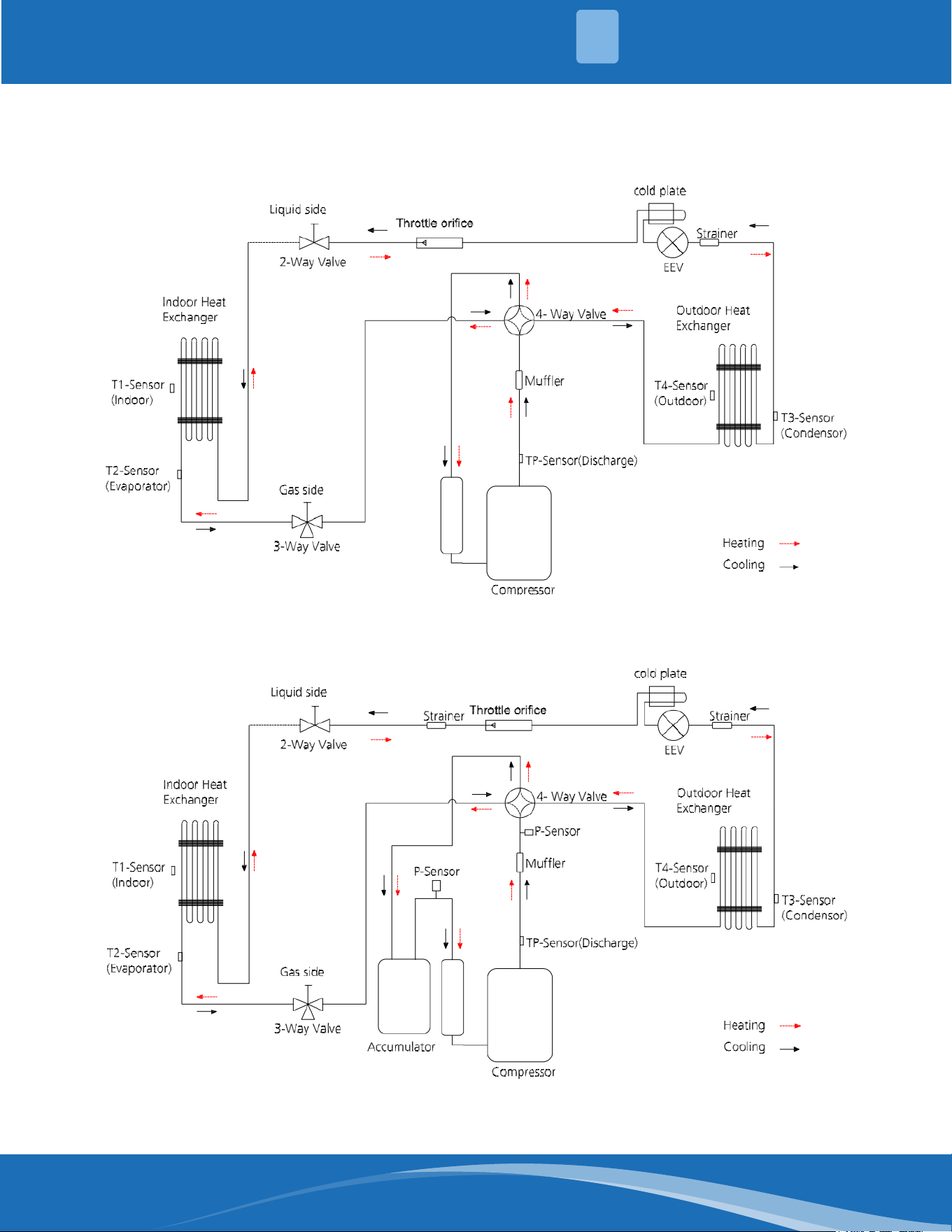
1.4 Refrigerant Cycle Diagrams
DIY-09-HP-WMAH-115D25-O & DIY-12-HP-WMAH-115D25-O
DIY-09-HP-C-115D25-O & DIY-12-HP-C-115D25-O
DIY-18-HP-WMAH-230D25-O & DIY-18-HP-C-230D25-O
mrcool.com 14
14
SYSTEM OVERVIEW
1
DIY-24-HP-WMAH-230D25-O & DIY-24-HP-C-230D25-O
DIY-36-HP-WMAH-230D25-O & DIY-36-HP-C-230D25-O
mrcool.com15
SYSTEM OVERVIEW
1
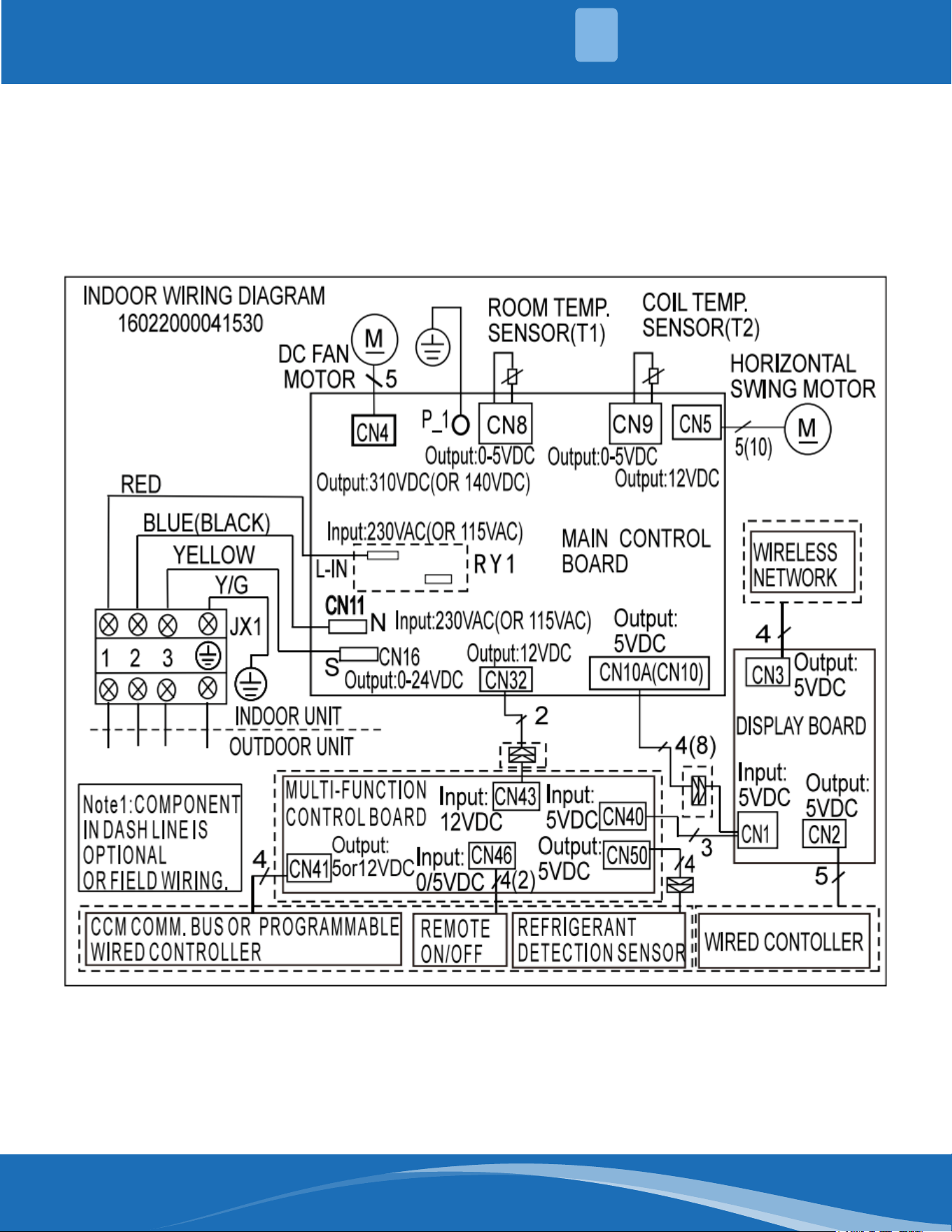
1.5 Electrical Wiring Diagrams
Indoor and outdoor unit wiring diagram:
Indoor Unit Outdoor Unit
IDU Model IDU Wiring Diagram ODU Model ODU Wiring Diagram
DIY-09-HP-WMAH-115D25-O
16022000041530
DIY-09-HP-C-115D25-O
16022000040956
DIY-12-HP-WMAH-115D25-O DIY-12-HP-C-115D25-O
DIY-18-HP-WMAH-230D25-O DIY-18-HP-C-230D25-O
16022000040313
DIY-24-HP-WMAH-230D25-O DIY-24-HP-C-230D25-O
DIY-36-HP-WMAH-230D25-O DIY-36-HP-C-230D25-O 16022000040650
Outdoor unit printed circuit board diagram:
Outdoor Unit
ODU Model ODU Printed Circuit Board
DIY-09-HP-C-115D25-O
17122000062141
DIY-12-HP-C-115D25-O
DIY-18-HP-C-230D25-O 17122000048066
DIY-24-HP-C-230D25-O 17122000048064
DIY-36-HP-C-230D25-O 17122300007152
mrcool.com 16
16
SYSTEM OVERVIEW
1
Indoor unit wiring diagram: 16022000041530
mrcool.com17
SYSTEM OVERVIEW
1
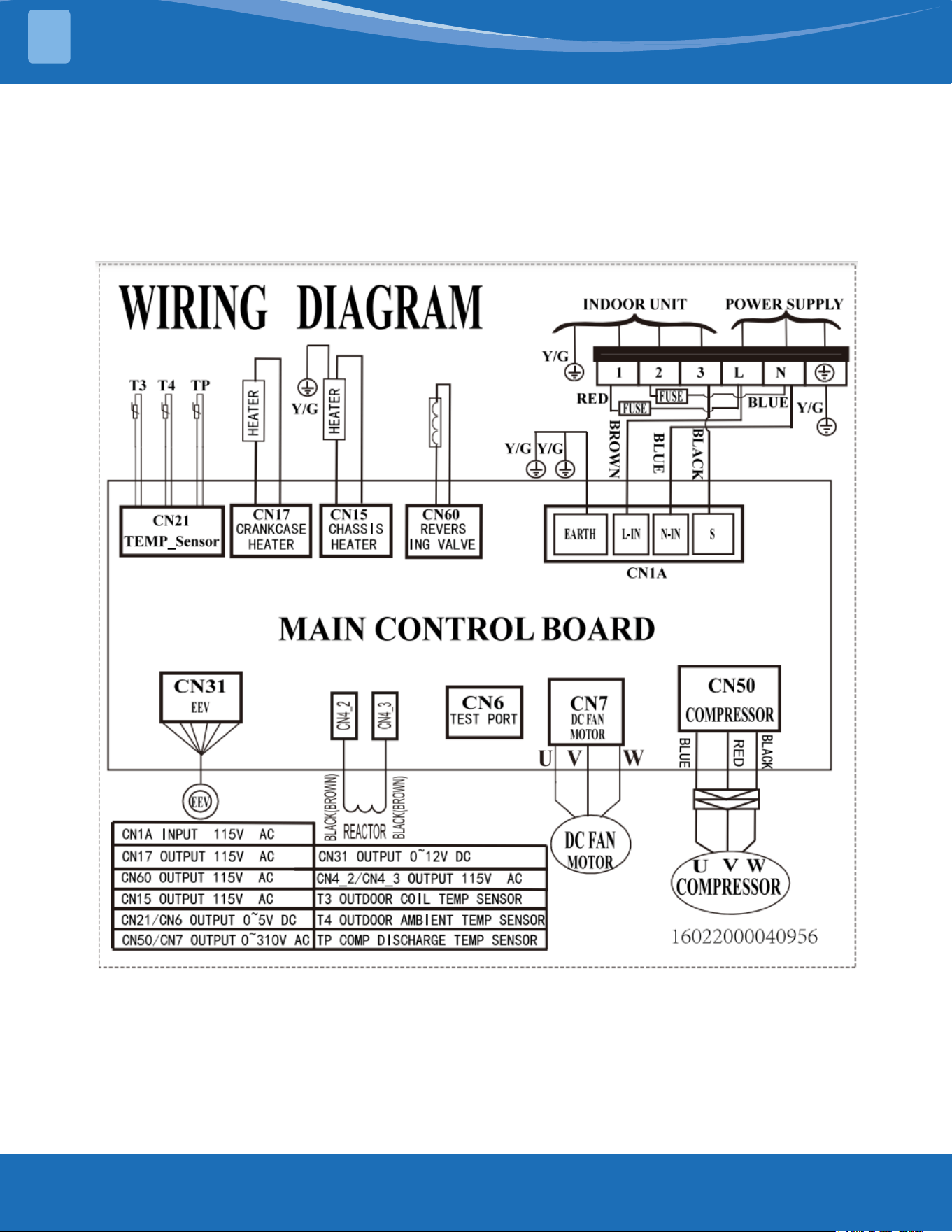
Outdoor unit wiring diagram: 16022000040956
mrcool.com 18
18
SYSTEM OVERVIEW
1
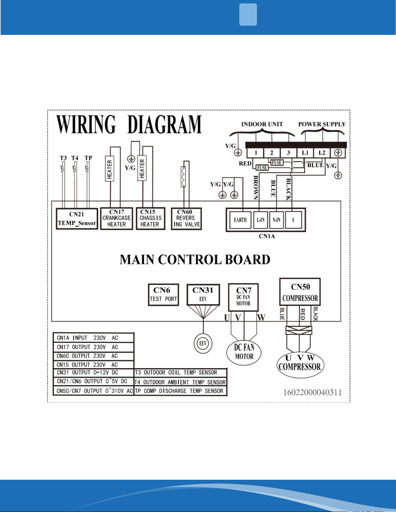
Outdoor unit wiring diagram: 16022000040311
mrcool.com19
SYSTEM OVERVIEW
1
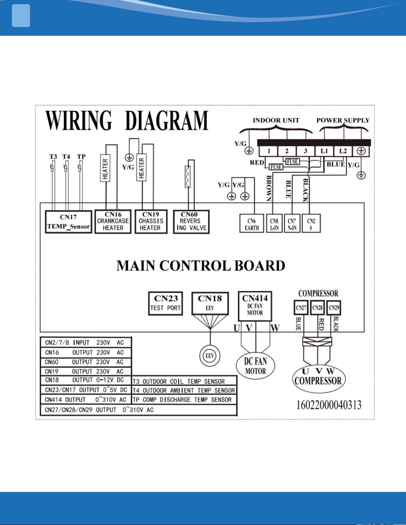
Outdoor unit wiring diagram: 16022000040313
mrcool.com 20
20
SYSTEM OVERVIEW
1
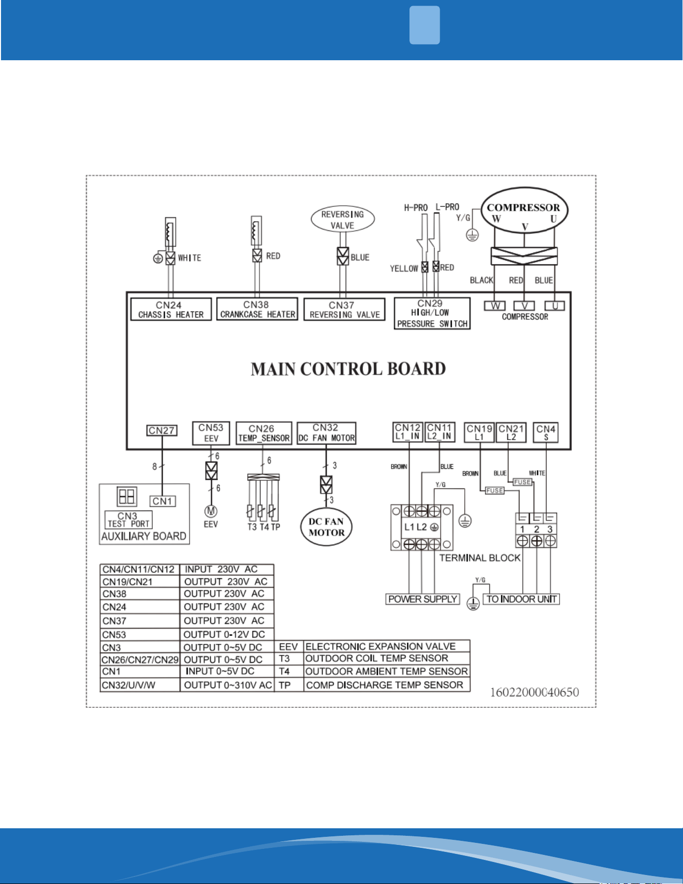
Outdoor unit wiring diagram: 16022000040650
mrcool.com21
SYSTEM OVERVIEW
1
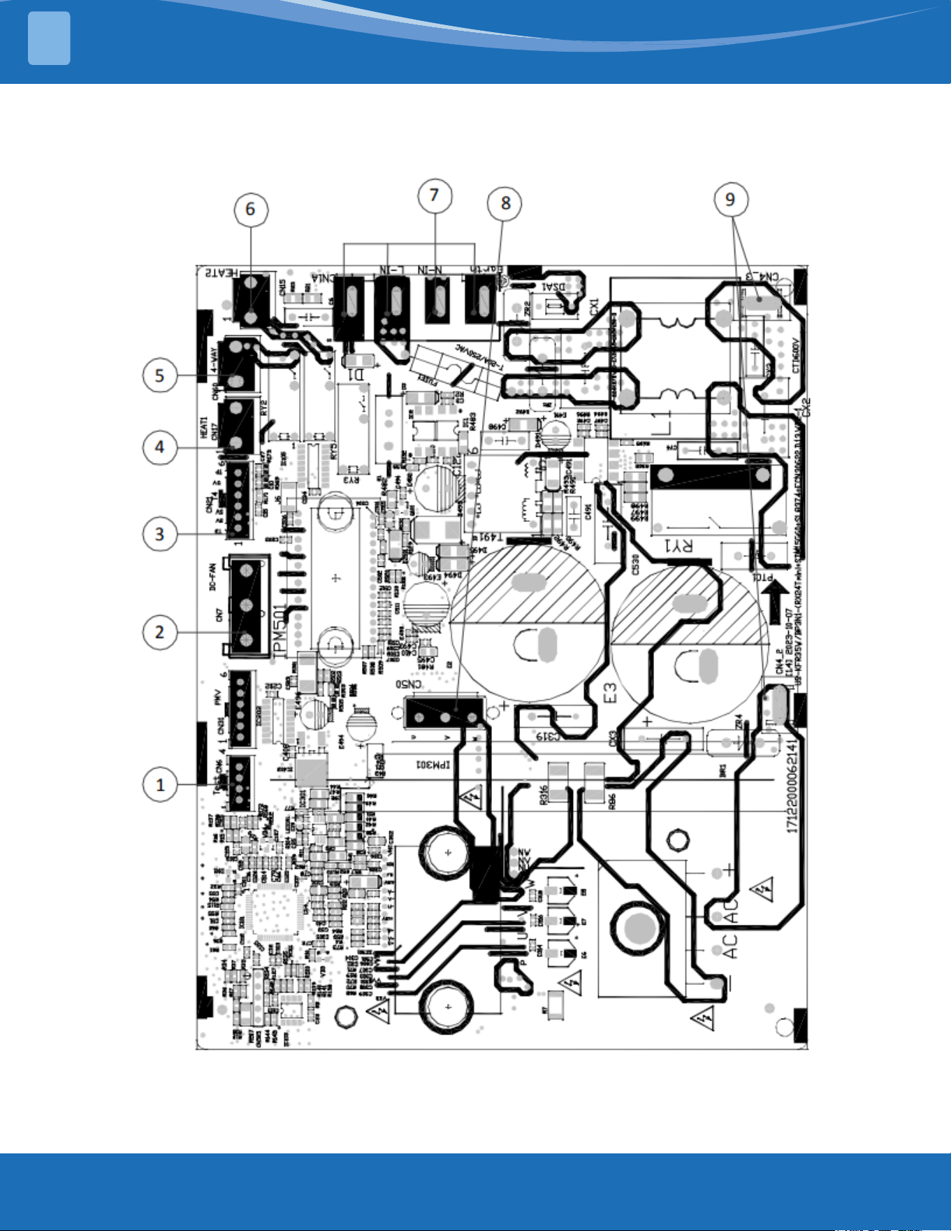
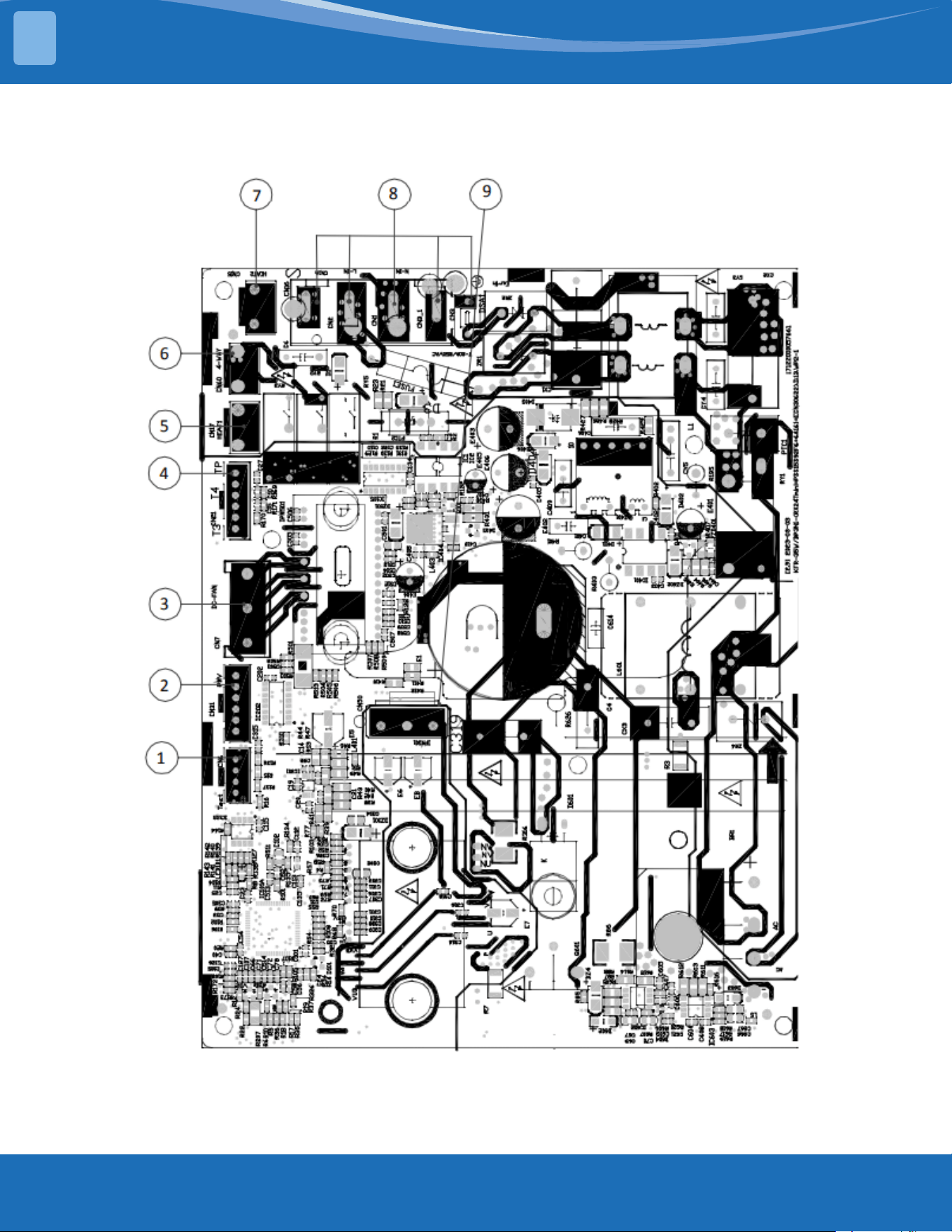
Outdoor unit printed circuit board diagram: 17122000062141
mrcool.com 22
22
SYSTEM OVERVIEW
1
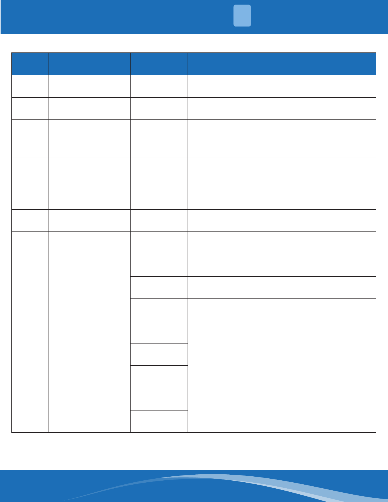
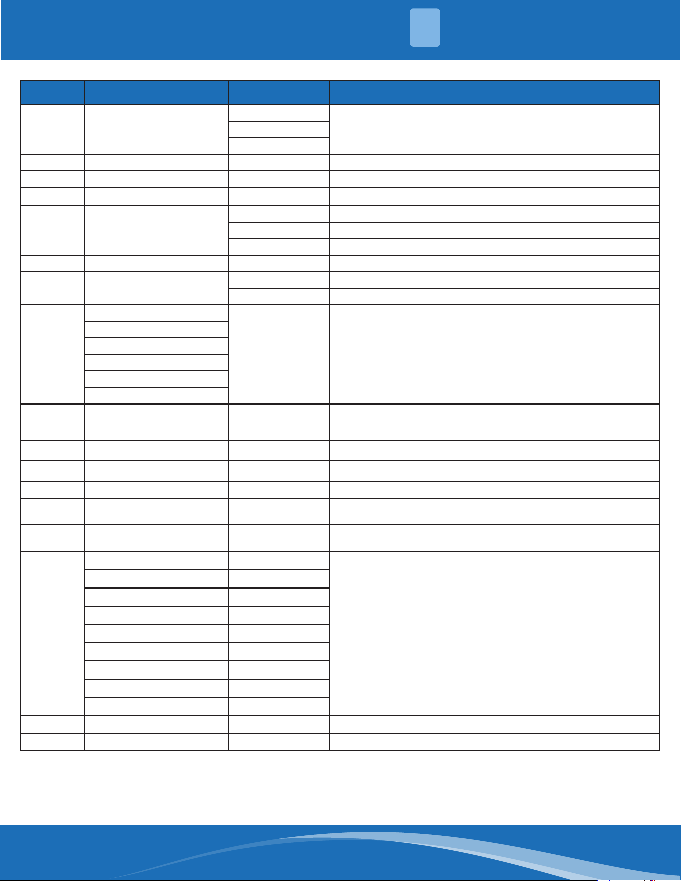
No. Name NC# Meaning
1 TESTPORT CN6 Used for testing (Output: 0-5VDC)
2 DC-FAN CN7 Connect to DC fan (Output: 0-310VAC)
3 TP T4 T3 CN21
Connect to pipe temp. sensor T3, ambient temp. sensor
T4, exhaust temp. sensor TP (output: 0-5VDC)
4 HEAT1 CN17 Connect to compressor heater, 115VAC when is ON
5 4-WAY CN60 Connect to 4 way valve, 115VAC when is ON
6 HEAT2 CN15 Connect to chassis heater, 115VAC when is ON
7 CN1A
/ S: connect to indoor unit communication
/ L_in: connect to L-line (115VAC input)
/ N_in: connect to N-line (115VAC input)
/ Earth
8 CN50
W
Connect to compressor .0VAC (standby), 0-310VAC
(running)
V
U
9 REACTOR
CN4_2
Connect to reactor, 115VAC when is ON
CN4_3
Note: This section is for reference only. Please take practicality as standard.
mrcool.com23
SYSTEM OVERVIEW
1
Outdoor unit printed circuit board diagram: 17122000057661
mrcool.com 24
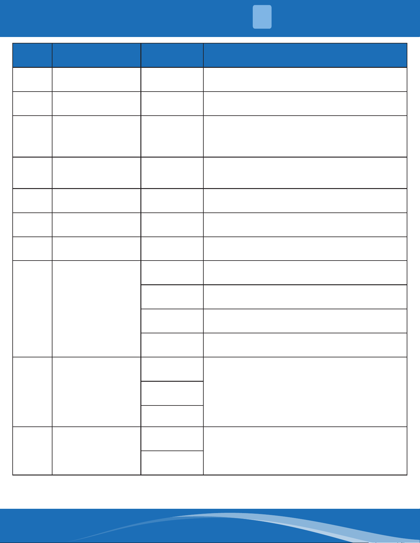
No. Name NC# Meaning
1 TESTPORT CN6 Used for testing
2 PMV CN31 Connect to electric expansion valve (Output: 0-20VDC)
3 DC-FAN CN7 Connect to DC fan (Output: 0-310VAC)
4 TP T4 T3 CN21
Connector to pipe temp sensor T3, ambient temp
sensor T4, exhaust temp., sensor TP (Output: 0-310VDC)
5 HEAT1 CN17 Connect to compressor heater (Output: 230VAC)
6 4-WAY CN60 Connect to 4 way valve (Output: 230VAC)
7 HEAT2 CN15 Connect to chassis heater (Output: 230VAC)
8 CN1A
/ S: connect to indoor unit communication
/ L_in: connect to L-line (230VAC input)
/ N_in: connect to N-line (230VAC input)
/ Earth
9 CN50
W
Connect to compressor (Output: 0-310VAC)
V
U
9 REACTOR
CN4_2
Connect to reactor, 115VAC when is ON
CN4_3
Note: This section is for reference only. Please take practicality as standard.
SYSTEM OVERVIEW
1
mrcool.com25
SYSTEM OVERVIEW
1
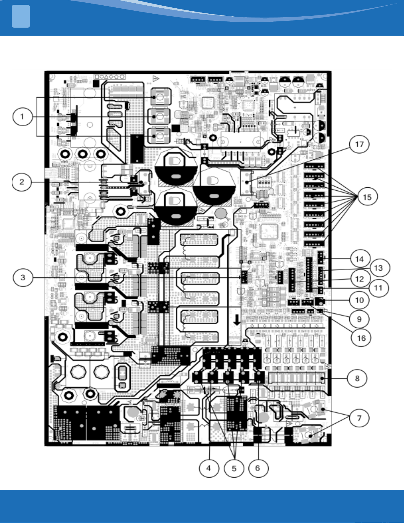
Outdoor unit printed circuit board diagram: 17122000048064 & 17122000048066
mrcool.com 26
26
SYSTEM OVERVIEW
1
No. Name NC# Meaning
1 Compressor
W
Connect to compressor (Output: 0-310VAC)
V
U
2 DC-FAN CN32 Connect to DC fan (Output: 0-310VAC)
3 TESTPORT CN45 Used for testing
4 HEAT_Y CN38 Connect to compressor heater (Output: 230VAC)
5 4-WAY
CN37 Connect to 4 way valve 1 (Output: 230VAC)
CN25 Connect to 4 way valve 2 (Output: 230VAC)
CN42 Connect to 4 way valve 3 (Output: 230VAC)
6 HEAT_D CN24 Connect to chassis heater (Output: 230VAC)
7 POWER SUPPLY
CN11 N_in: connect to N-line (230VAC input)
CN12 L_in: connect to L-line (230VAC input)
8
S-A
CN43 S: connect to indoor unit communication (230VAC input)
S-B
S-C
S-D
S-E
S-F
9 TBH-IN TBH-OUT T3B TF CN9
Connect to cold plate inlet temp. sensor TBH-IN, cold plate outlet
temp sensor TBH-OUT, Condenser coil middle temp. sensor T3B,
refrigerant tube inlet temp. sensor TF
10 OLP TEMP. SENSOR CN30 Connect to compressor top temp. sensor (Output: 0-50VDC)
11 T2B CN28 Connect to evaporator coil outlet temperature sensor T2B
12 / CN27 Connect to key board CN1
13 T3 T4 TP CN26
Connect to condenser coil temp. sensor T3, ambient temp. sensor
T4, exhaust temp. sensor TP (Output: 0-50VDC)
14 H-PRO, L-PRO CN29
Connect to high and low pressure switch (pin1 - pin2 & pin3 - pin 4:
5VDC pulse wave)
15
EEVA CN17
Connect to electric expansion valve (Output: 0-12VDC)
EEVB CN16
EEVC CN22
EEVD CN14
EEVE CN13
EEVF CN1
EEV1 CN53
EEV2 CN44
EEV3 CN3
16 H_YL CN49 Connect to high pressure sensor
17 DC-FAN2 CN10 Connect to DC fan (Output: 0-310VAC)
Note: This section is for reference only. Please take practicality as standard.
mrcool.com27
PRODUCT FEATURES
2
2.2 Safety Features
Compressor Three Minute Delay at Restart:
Compressor functions are delayed for up to ten seconds upon the rst startup of the unit, and are
delayed for up to three minutes upon subsequent unit restarts.
Automatic Shuto Based on Discharge Temperature:
If the compressor discharge temperature exceeds a certain level for a period of time, the compressor
ceases operation.
Automatic Shuto Based on Fan Speed:
If the indoor fan speed registers below 200RPM or over 2100RPM for an extended period of time, the
unit ceases operation and the corresponding error code is displayed on the indoor unit.
Inverter Module Protection:
The inverter module has an automatic shuto mechanism based on the unit's current, voltage, and
temperature. If the automatic shuto is initiated, the corresponding error code is displayed on the
indoor unit and the unit ceases operation.
Indoor Fan Delayed Operation:
• When the unit starts, the louver is automatically activated and the indoor fan will operate after a
period of setting time or the louver is in place.
• If the unit is in heating mode, the indoor fan is regulated by the anti-cold wind function.
Sensor Redundancy and Automatic Shuto:
• If one temperature sensor malfunctions, the air conditioner continues operation and displays the
corresponding error code, allowing for emergency use.
• When more than one temperature sensor is malfunctioning, the air conditioner ceases operation.
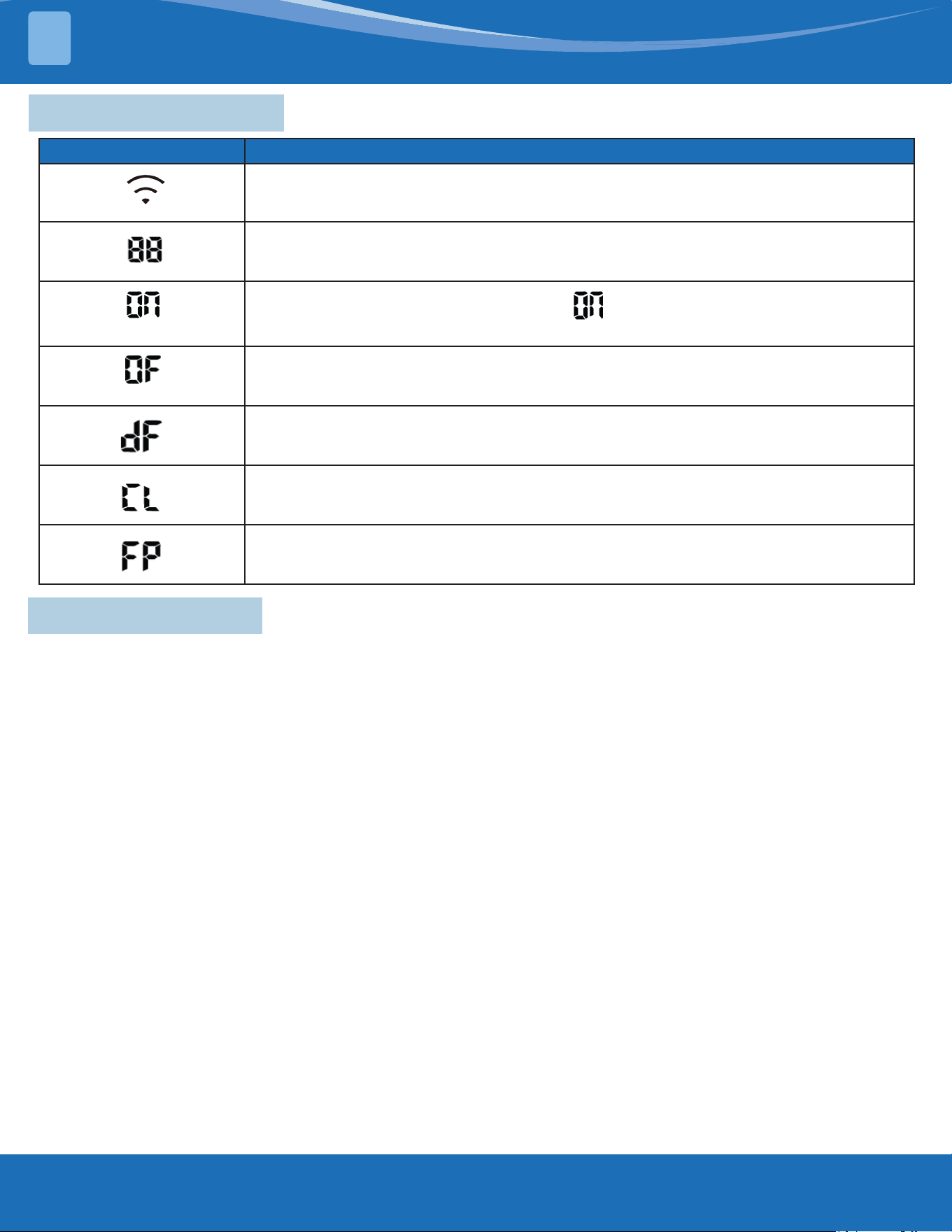
Display Code Display Code Meaning
• When Wireless Control feature is activated (For APP control units)
• Displays temperature, operation feature and Error codes:
(for 3 seconds)
• TIMER ON is set (if the unit is OFF, “ ” remains on when TIMER ON is set).
• SWING, TURBO or SILENCE feature is turned on.
(for 3 seconds)
• TIMER OFF is set.
• SWING, TURBO or SILENCE feature is turned o.
• When defrosting.
• When Active Clean feature is turned on.
• When 46°F (8°C) heating feature is turned on.
2.1 Display Functions
mrcool.com 28
28
PRODUCT FEATURES
2
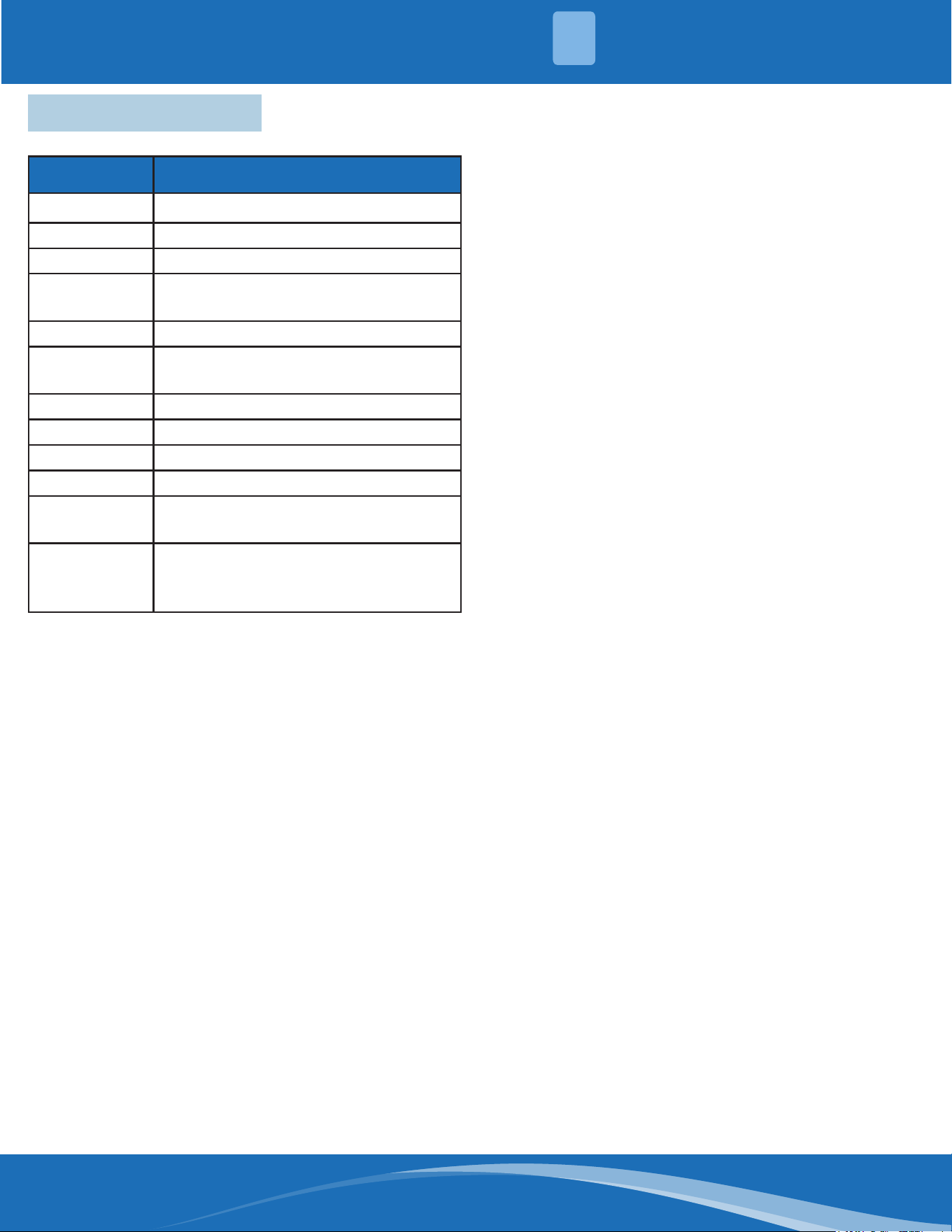
2.3 Basic Functions
Abbreviation Element
T1 Indoor room temperature sensor
T2 Evaporator coil temperature sensor
T3 Condenser coil temperature sensor
T4
Outdoor ambient temperature
sensor
Tsc Adjusted setting of temperature
TP
Compressor discharge temperature
sensor
CDIFTEMP Cooling shutdown temperature
HDIFTEMP2 Heating shutdown temperature
TCDI1 Enter defrost temperature
TCDE1 Exit defrost temperature 1
TCDE2
Exit defrost temperature2 (maintain
for a period of time)
TIMING_
DEFROST_
TIME
Enter defrost time
Unit Element Abbreviations:
In this manual, such as CDIFTEMP, HDIFTEMP2,
TCDE1, TCDE2, TIMING_DEFROST_TIME...etc, they
are well-setting parameter of EEPROM.
When fan mode is activated:
• The outdoor fan and compressor cease
operation.
• Temperature control is disabled and indoor
room temperature is displayed.
• The indoor fan speed can be set to 1%-100%,
or auto.
• The louver operations are identical to those in
cooling mode.
• Auto fan: In fan-only mode, AC operates the
same as auto fan in cooling mode with the
temperature set at 75°F (24°C).(Tsc=75°F
(24°C)).
Reach the congured temperature:
1. When the compressor runs continuously for
within 120 minutes.
• If the following conditions are satised, the
compressor ceases operation.
• Calculated frequency(fb) is less than
minimum limit frequency(FminC).
• Compressor runs at FminC more than 10
minutes.
• T1 is lower than or equal to (Tsc-CDIFTEMP-
32.9°F (0.5°C)).
Note: CDIFTEMP is EEPROM setting parameter. It is
35.6°F (2°C)).
2. When the compressor runs continuously for
more than 120 minutes:
• If the following conditions are satised, the
compressor ceases operation.
• Calculated frequency(FB) is less than
minimum limited frequency(FminC).
• Compressor runs at FminC more than 10
minutes.
• T1 is lower than or equal to (Tsc-CDIFTEMP).
Note: CDIFTEMP is EEPROM setting parameter. It is
35.6°F (2°C) usually.
3. If one of the following conditions is satised,
not judge protective time:
• Compressor running frequency(fr) is more
than test frequency (TestFre).
• Compressor running frequency is equal to
test frequency, T4 is more than 59°F (15°C)
or T4 fault.
• Change setting temperature.
• Turn on/o turbo or sleep function.
• Various frequency limit shutdown occurs.
Compressor Control:
Fan Mode:
Cooling Mode:
mrcool.com29
PRODUCT FEATURES
2
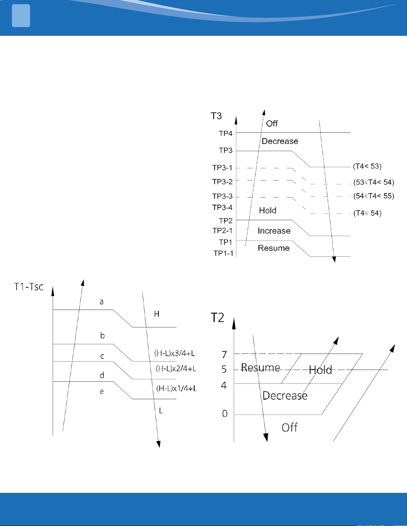
1. In cooling mode, the indoor fan operates
continuously. The fan speed can be set to 1%-
100%, or auto.
2. Auto fan.
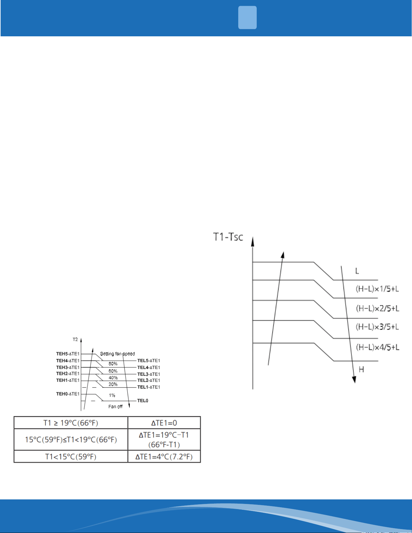
For DC fan motor units:
• Descent curve
• When T1-Tsc is lower than 6.3°F (3.5°C), fan
speed reduces to 80%.
• When T1-Tsc is lower than 1.8°F (1°C), fan
speed reduces to 60%.
• When T1-Tsc is lower than 0.9°F (0.5°C), fan
speed reduces to 40%.
• When T1-Tsc is lower than 0°F (0°C), fan
speed reduces to 20%.
• When T1-Tsc is lower than -0.9°F (-0.5°C), fan
speed reduces to 1%.
• Rise curve
• When T1-Tsc is higher than or equal to 0°F
(0°C), fan speed increases to 20%.
• When T1-Tsc is higher than or equal to 0.9°F
(0.5°C), fan speed increases to 40%.
• When T1-Tsc is higher than or equal to 1.8°F
(1°C), fan speed increases to 60%.
• When T1-Tsc is higher than or equal to 2.7°F
(1.5°C), fan speed increases to 80%.
• When T1-Tsc is higher than or equal to 7.2°F
(4°C), fan speed increases to 100%.
For AC fan motor units:
• The outdoor unit will be run at dierent fan
speeds according to T4 and compressor
running frequency.
• For dierent outdoor units, the fan speeds are
dierent.
Outdoor Fan Control:
Condenser Temperature
Protection:
When the condenser temperature exceeds
a congured value, the compressor ceases
operation.
Indoor Fan Control:
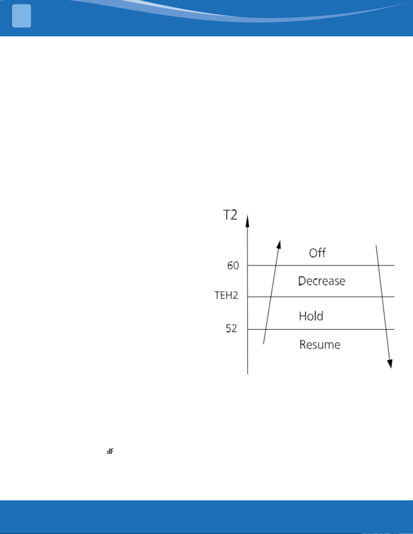
Evaporator Temperature
Protection:
• O: Compressor stops.
• Decrease: Decreases the running frequency to
lower level per 1 minute.
• Hold: Keep the current frequency.
• Resume: No limitation for frequency.
mrcool.com 30
30
PRODUCT FEATURES
2
Compressor Control:
1. Reach the congured temperature:
• If the following conditions are satised, the
compressor ceases operation.
• Calculated frequency(fb) is less than
minimum limit frequency(FminH).
• Compressor runs at FminH more than 10
minutes.
• T1 is higher than or equal to Tsc+
HDIFTEMP2.
Note: HDIFTEMP2 is EEPROM setting parameter.
It is 35.6°F (2°C) usually.
• If one of the following conditions is satised,
do not judge protective time.
• Compressor running frequency(fr) is more
than test frequency(TestFre).
• When compressor running frequency is
equal to test frequency, T4 is more than 59°F
(15°C) or T4 fault.
• Change setting temperature.
• Turn on/o turbo or sleep function.
2. When the current is higher than the
predened safe value, surge protection is
activated, causing the compressor to cease
operations.
Indoor Fan Control:
1. In heating mode, the indoor fan operates
continuously. The fan speed can be set to
1%-100%, or mute. And the anti-cold wind
function has priority.
• Anti-cold air function
• The indoor fan is controlled by the indoor
temperature T1 and indoor unit coil
temperature T2.
2. Auto fan
For Dc fan motor units:
• Rise curve
• When T-Tsc is higher than -2.7°F (-1.5°C), fan
speed reduces to 80%.
• When T1-Tsc is higher than 0°F (0°C), fan
speed reduces to 60%.
• When T1-Tsc is higher than 0.9°F (0.5°C), fan
speed reduces to 40%.
• When T1-Tsc is higher than 1.86F (1°C), fan
speed reduces to 20%.
• Descent curve
• When T1-Tsc is lower than or equal to 0.9°F
(0.5°C), fan speed increases to 40%.
• When T1-Tsc is lower than or equal to 0°F
(0°C), fan speed increases to 60%.
• When T1-Tsc is lower than or equal to -2.7°F
(-1.5°C), fan speed increases to 80%.
• When T1-Tsc Is lower than or equal to 5.4°F
(-3°C), fan speed increases to 100%.
For AC fan motor units:
Outdoor Fan Control:
• The outdoor unit will be run at dierent fan
speeds according to T4 and compressor
running frequency.
• For dierent outdoor units, the fan speeds
are dierent.
Heating Mode:
mrcool.com31
PRODUCT FEATURES
2
Defrosting Mode:
• If any one of the following conditions is
satised, system will ender the defrosting
mode.
After the compressor starts up and keeps
running, take the lowest temp of T3 (between 7
to 12 minutes) as T30.
Condition 1: If the compressor cumulate running
time is up to 29 minutes and T3<TCDI2 and
T3≤T30-T30SUBT30ONE and T4<-7.6°F (-22°C)
(DEFROST_T4_ADD).
Condition 2: If the compressor cumulate running
time is up to 35 minutes and T3<TCDI2 and
T3≤T30-T30SUBT30TWO and T4<-7.6°F (-22°C)
(Defrost_T4_ADD).
Condition 3: If the compressor cumulate running
time is up to 29 minutes and T3<-24 (TCDI3_ADD)
for 3 minutes and T4>-7.6°F (-22°C) (DEFROST_
T4_ADD).
Condition 4: For the model active this condition
if the compressor cumulate running time is up to
120 minutes and T3<-5°F (-15°C) and T4<-7.6°F
(-22°C).
Condition 5: This is just for the rst time defrost
after power on condition, on the scenario when
rst time defrost or power o and power back
on or turn on from standby mode you need to
check the ice accumulate situation (the defrost
time reckon reset), when the compressor
cumulate4 running time is up to 30 minutes T4-
T3<(0.5T4+KDELTT_ADD) and T3<TCDIN5_ADD,
T4<-7.6°F (-22°C).
Condition 6: For the model active this condition
if the compressor cumulate running time is
up to TIMING_DEFROST_TIME (Hour) and T4≤-
7.6°F (-22°C)(DEFROST_T4_ADD), the T4 without
malfunction.
Condition 7: When T3 or T4 is lower than 41°F
(-3°C) (last for 30 seconds) cumulate running for
(EE-TIME-DEFROST7_ADD+30) minutes (not need
based on T30 keep running with minimum 10
minutes).
Condition 8: When T3 or T4 is lower than 26.6°F
(-3°C) (last for 30 seconds) cummulate running
for (EE_TIME_DEFROST7_ADD+30) minutes (It will
run a minimum of 10 minutes not needing to be
based on T30).
• In defrosting mode, the compressor continues
to run, the indoor and outdoor motor will case
operation, the defrost light of the indoor unit
will turn on, and the " " symbol is displayed.
• Condition 1-5, if any one of the following
conditions is satised, defrosting ends and the
machine switches to normal heating mode.
• T3 rises above TCDE1.
• T3 maintained above TCDE2 for 80 seconds.
• Unit runs for 15 minutes consecutively in
defrosting mode.
• Condition 6, if any one of the following
conditions is satised, defrosting ends and the
machine switches to normal heating mode.
• Unit runs for 10 minutes consecutively in
defrosting mode.
• T3 rises above 50°F (10°C).
• Condition 7-8, if any one of the following
conditions is satised, defrost ends and the
machine switches to normal heat mode.
• T3 rises above TCDE1+7.2°F (4°C)
• T3 maintained above TCDE2+7.2°F (4°C) for
80 seconds.
• Unit runs for 15 minutes consecutively in
defrosting mode.
Evaporator Temperature
Protection:
• O: Compressor stops.
• Decrease: Decreases the running frequency
to the lower level per 20 seconds.
• Hold: Keep the current frequency.
• Resume: No limitation for frequency.
• This mode can be selected with the remote
controller and the setting temperature can
be changed between 60°F-86°F (16°C-30°C).
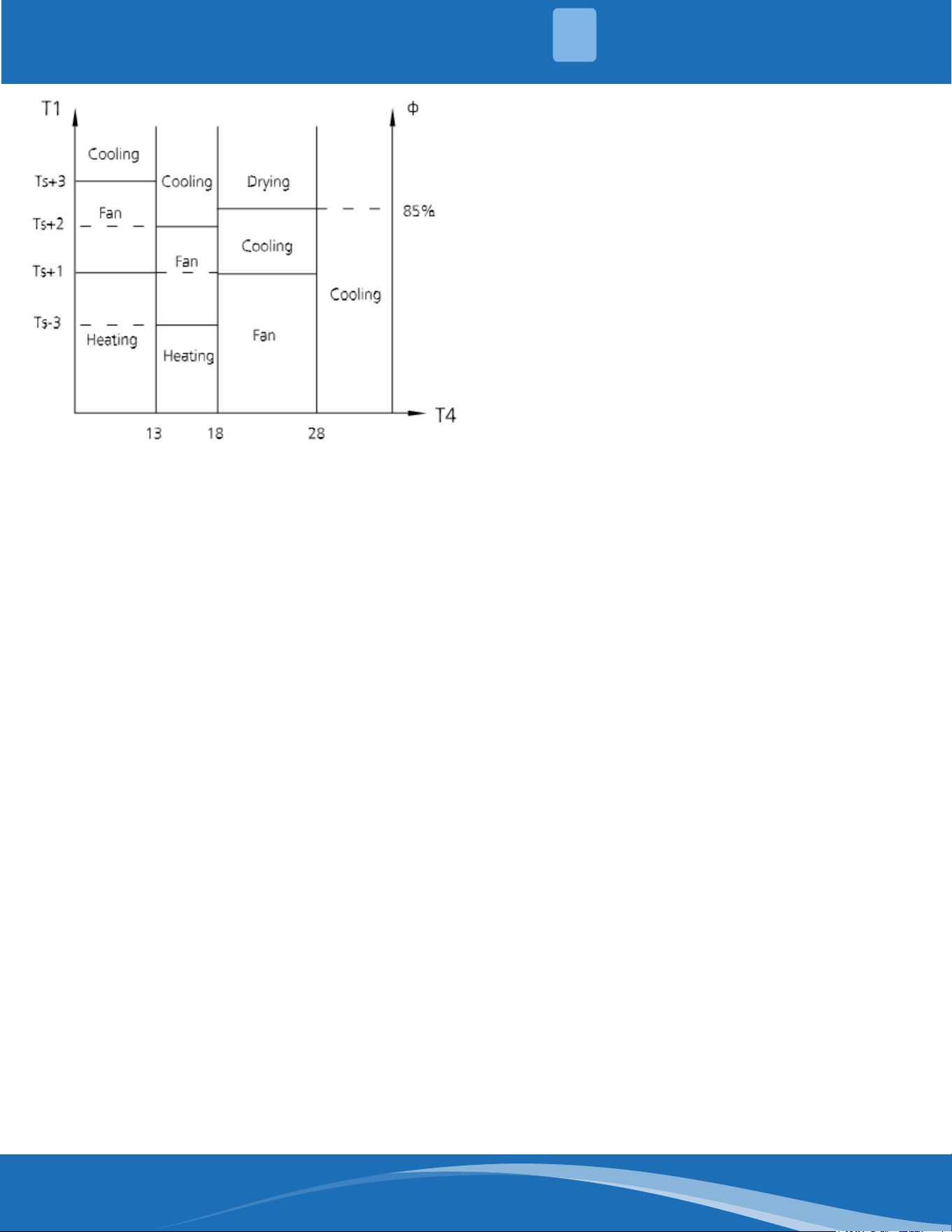
• In auto mode, the machine selects cooling,
heating, auto-drying, or fan-only mode on
the basis of T1, Ts, T4 and relative humidity.
Auto Mode:
mrcool.com 32
32
PRODUCT FEATURES
2
• If the setting temperature is modied, the
machine selects a new running function.
• In drying mode, the unit operates the same
as auto fan in cooling mode.
• All protections are activated and operate the
same as they do in cooling mode.
Low room temperature protection
If the room temperature is lower than 50°F
(10°C), the compressor ceases operation and
does not resume until the room temperature
exceeds 53.6°F (12°C).
Forced cooling mode:
The compressor and outdoor fan continue to
run (xed at rated frequency), and the indoor
fan runs at rated speed. After running for 30
minutes, the unit will switch to auto mode with
a preset temperature of 76°F (24°C).
Forced auto mode:
Forced auto mode operates the same as normal
auto mode with a preset temperature of 76°F
(24°C).
• The unit exits forced operation when it
receives the following signals:
• Switch on
• Switch o
• Timer on
• Timer o
• Sleep mode
• Follow me
• Changes in:
• Mode
• Fan Speed
• Setting temperature
Forced defrosting mode
• Press the AUTO/COOL button continuously
for 5s under forced cooling mode to enter this
mode.
• Indoor fan will stop, defrosting lamp will light
on
• Quit this mode and turn o the unit when:
• Quit normal defrosting
• Turned o by remote
• Press AUTO/COOL button continuously for 5s
again
• Timing range is 24 hours
• Timer on: The machine will turn on
automatically when reaching the setting time.
• Timer o: The machine will turn o
automatically when reaching the setting time.
• Timer on/o: The machine will turn on
automatically when reaching the setting "on"
time, and then turn o automatically when
reaching the setting "o" time.
• The timer function will not change the units
operation mode. Suppose the unit is o now,
it will not start up on start after setting the
"timer o" function and when reaching the
setting time, the timer LED will be o and the
units running mode will not be changed.
• The setting time is relative time.
• The unit will quit the timer function when it
has malfunctioned.
• The indoor unit has an auto-restart module
that allows the unit to restart automatically.
The module automatically stores the current
settings and in case of sudden power failure,
will restore those settings automatically within
3 minutes of power returning.
• If there is a power failure while the unit is
running, the compressor starts 3 minutes
after the unit restarts. If the unit was already
o before the power failure, the unit will be in
standby mode.
Drying Mode:
Forced Operation Function:
Timer Function:
Auto Restart Function:
mrcool.com33
PRODUCT FEATURES
2
The sleep function is available in cooling, heating,
or auto mode.
The operational process for sleep mode is as
follows:
• When cooling, the temperature rises 1.8°F
(1°C) (no higher than 86°F (30°C)) every hour.
After 2 hours, the temperature stops rising
and the indoor fan is xed at a low speed.
• When heating the temperature decreases
1.8°F (1°C)(no lower than 60.8°F (16°C) every
hour. After 2 hours, the temperature stops
decreasing and the indoor fan is xed at a low
speed. The anti-cold wind function will take
priority.
• The operating time for sleep mode is 8 hours,
after which the unit will exit this mode.
• The timer setting is available in this mode.
• The active clean technology washes away
dust, mold, and grease that may cause odors
when it adheres to the heat exchanger by
automatically freezing and then rapidly
thawing the frost. The internal wind wheel
then keeps operating to blow-dry the
evaporator, thus preventing the growth of
mold and keeping the inside clean.
• When this function is turned on, the indoor
unit displays "CL", after 20 to 130 minutes, the
unit will turn o automatically and cancel the
active clean function.
• If you press "Follow Me" on the remote, the
indoor unit will beep. This indicates the follow
me function is active.
• Once active the remote control will send a
signal every 3 minutes with no beeps. The unit
automatically sets the temperature according
to the measurements from the remote
control.
• The unit will only change modes if the
information from the remote control makes
it necessary, not from the units temperature
setting.
• If the unit does not receive a signal for 7
minutes or you press "Follow Me" the function
turns o. The unit regulates temperature
based on its own sensor and settings.
In heating mode, the temperature can be set to
as low as 46.4°F (8°C) preventing the indoor area
from freezing if in a unoccupied space during
cold weather.
Press "Silence" on the remote control to enable
the SILENCE function. While this function is active,
the indoor unit will run at a faint breeze (1%
fan speed), which reduces noise to the lowest
possible level.
• Used to enter energy ecient mode.
• Under cooling mode, press ECO button
and the remote control will adjust the
temperature automatically to 75.2°F (24°C)
and the fan speed to Auto to save energy
(but only if the set temperature is less than
75.2°F (24°C).
• If the set temperature is more than 75.2°F
(24°C) and 86°F (30°C) press the ECO button
and the fan speed will change to auto and
the set temperature will remain unchanged.
• When the unit receives signals such as switch
o, turbo, silence, self clean, forced cooling,
mode change, sleep mode, or adjusting the
set temperature to less than 76°F (24°C), it
will cease ECO operation.
• When there is any temperature sensor
malfunction the unit will cease ECO mode.
• The indoor fan will run in auto fan
mode when put into ECO mode. The set
temperature and fan speed can be changed
by the remote.
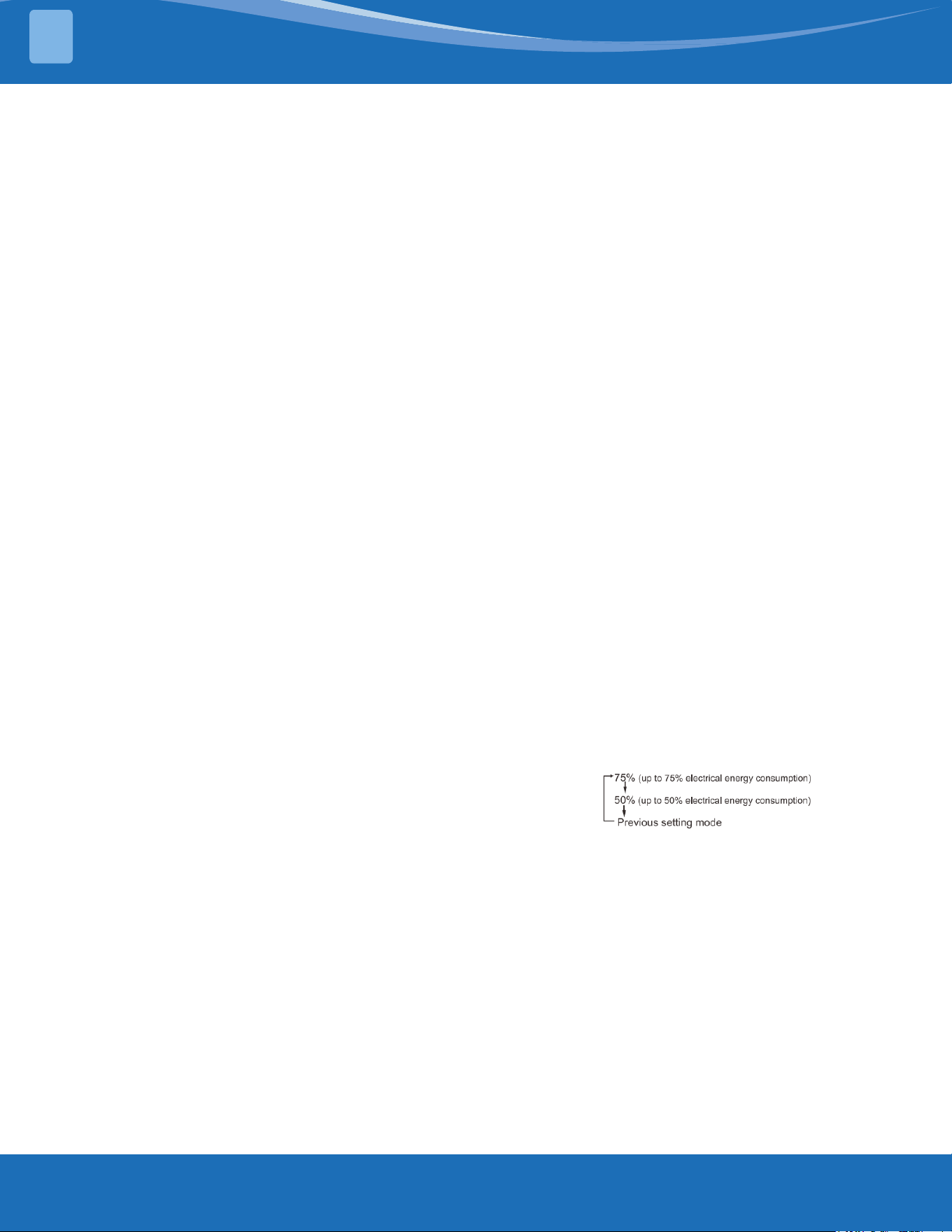
Press the " Gear" Button on the remote
control to enter energy ecient mode in a
sequence of the following:
Turn o the unit or activate ECO, sleep, turbo, FP,
silence, or self clean to quit this function.
This feature avoids direct airow from blowing on
the body.
Note: this feature is only available under cool,fan-
only, or dry mode.
Wireless control allows you to control your air
conditioner using your phone.
Sleep Function
Active Clean Function:
Follow Me:
FP Mode 46.4°F (8°) Heating:
Silence
ECO Function:
Electrical Energy Consumption
Control:
Breeze Away:
Wireless Control (APP):
mrcool.com 34
34
REFRIGERANT RECHARGE
3
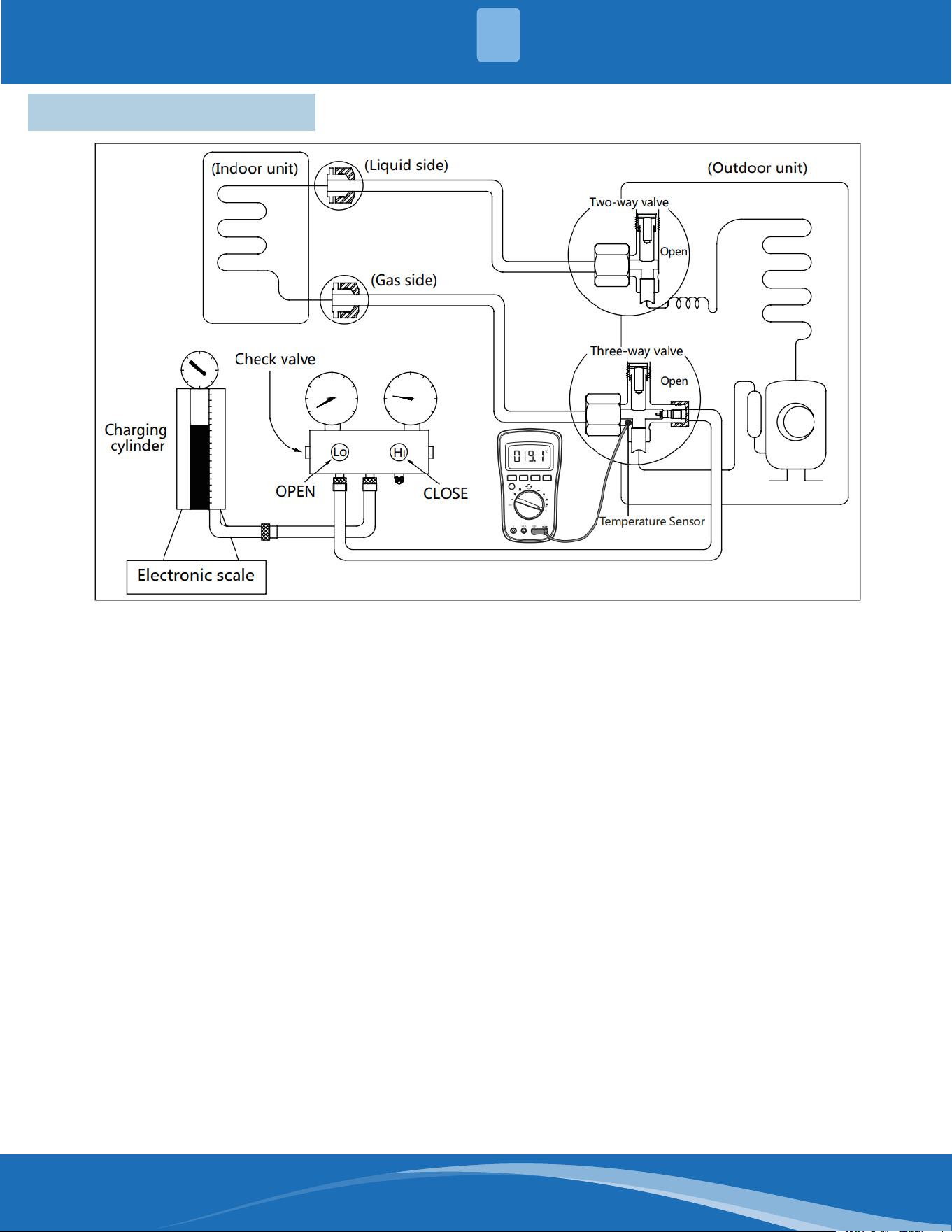
3.1 Refrigerant Recharge
1. Close both 2 and 3 way valves.
2. Slightly connect the handle Lo charge hose to
the 3 way service port.
3. Connect the charge hose to the valve at the
bottom of the refrigerant cylinder.
4. If the refrigerant is R410A/R32, invert the
cylinder to ensure a complete liquid charge.
5. Open the valve at the bottom of the cylinder
for 5 seconds to purge the air in the charge
hose, then fully tighten the charge hose with a
push pin Handle Lo to the service port of the
3-way valve.
6. Place the charging cylinder onto an electronic
scale and record the starting weight.
7. Fully open the Handle Lo manifold valve,
2-way and 3-way valves.
Procedure:
8. Operate the air conditioner in cooling mode to
charge the system.
9. When the electronic scale displays the correct
weight (refer to the gauge and the pressure of
the low side to conrm, the value of pressure
refers to chapter System Pressure Table) turn
o the air conditioner then close Lo manifold
valve and cylinder valve and disconnect the
charge hose from the 3-way service port
immediately.
10. Mount the caps back to the 2-way and 3-way
valves.
11. Use a torque wrench to tighten the caps to a
torque spec of 13.28ft. lbs (18Nm).
12. Check for any leaks.
mrcool.com35
TROUBLESHOOTING
4
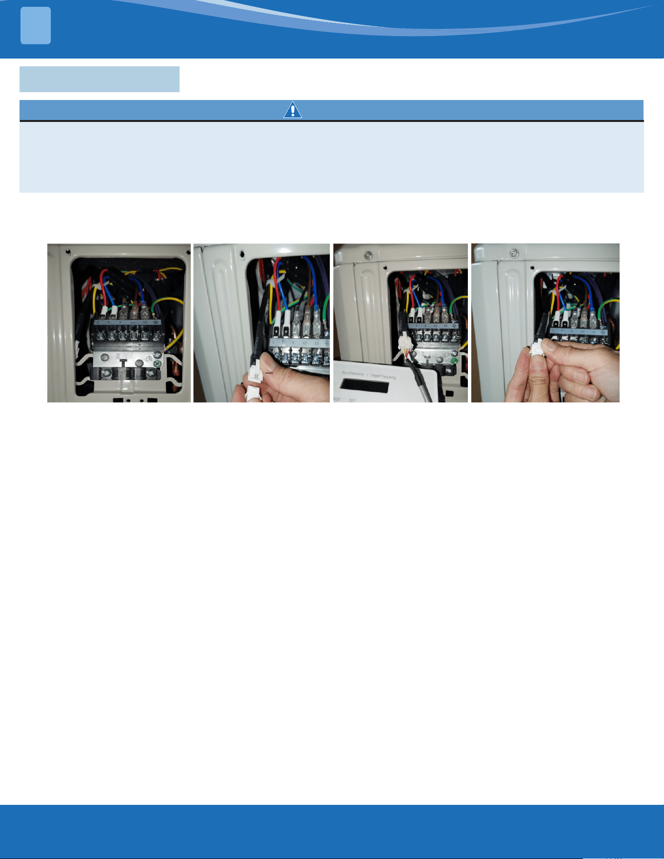
4.1 Safety Caution
WARNING
Be sure to turn o all power supplies or disconnect all wires to avoid electric shock. While checking the
indoor/outdoor PCB, please equip yourself with anti-static gloves or a wrist strap to avoid damaging
the board.
Electricity will remain in capacitors even when the power supply is o. Ensure the capacitors are fully
discharged before troubleshooting
Note: If using the inverter test tool for maintenance, remove the big handle from the unit, take out
the detection cable, take out the female end of the cable, and connect the inverter testing tool. After
maintenance is completed, insert the female end back into the port.
Note: This picture is for reference only. Actual appearance may vary.
mrcool.com 36
36
TROUBLESHOOTING
4
4.2 Error Display (Indoor Unit)
Display Error Information Solution
DF
Defrost
Normal Display, not
error code
CL
Active Clean
FP
Heating in Room Temperature under 46.4°F (8°C)
FC
Forced Cooling
AP
AP Mode of Wi Connection
CP
Remote Switched O
EH 00
IDU EEPROM Malfunction TS01-IDU
EH 0A
Indoor EEPROM Parameter Error TS01-IDU
EL 01
IDU & ODU Communication Error TS02-S-INV
EH 02
Zero-Crossing Signal Detection Error TS03
EH 03
IDU Fan Speed Out of Control TS04-S-IDU
EC 51
ODU EEPROM Parameter Error TS01-ODU
EC 52
ODU Coil Temperature Sensor (T3) Error TS05-ODU
EC 53
ODU Ambient Temperature Sensor (T4) Error TS05-ODU
EC 54
Comp. Discharge Temperature Sensor (TP) Error TS05-ODU
EC 56
IDU Coil Outlet Temperature Sensor (T2B) Error (Multi-Zone) TS05-ODU
EH 60
IDU Room Temperature Sensor (T1) Error TS05-IDU
EH 61
IDU Pipe Temperature (T2) Sensor Error TS05-IDU
EC 07
ODU Fan Speed Out of Control TS04-ODU
EH 0B
IDU Main Control Board & Display Board Communication Error TS07
FH CC
Refrigerant Sensor Error TS05-N10
EH C1
Refrigerant Sensor Detects Leakage TS06-N10
EH C2
Refrigerant Sensor is Out of Range & Leakage is Detected TS06-N10
EH C3
Refrigerant Sensor is Out of Range TS05-N10
EC C1
Other IDU Refrigerant Sensor Detects Leakage (Multi-Zone) TS06-N10
EL 0C
System Lacks Refrigerant TS06-INV
PC 00
ODU IPM Module Protection TS09-S
PC 01
ODU Voltage Protection TS10-S
PC 02
Compressor Top (or IPM) Temperature Protection TS11-S-INV
PC 04
Inverter Compressor Drive Error TS12-S
PC 03
Pressure Protection (low or high pressure) TS26-INV
PC 0L
Low Ambient Temperature Protection LP
----
IDUs Mode Conict (Multi-Zone) TS14
For other errors:
The display board may show a garbled code or a code
undened by the service manual. Ensure that this
code is not a temperature reading.
Troubleshooting:
Test the unit using the remote control. If the unit does
not respond to the remote, the indoor PCB requires
replacement. If the unit responds, the display board
requires replacement.
mrcool.com37
TROUBLESHOOTING
4
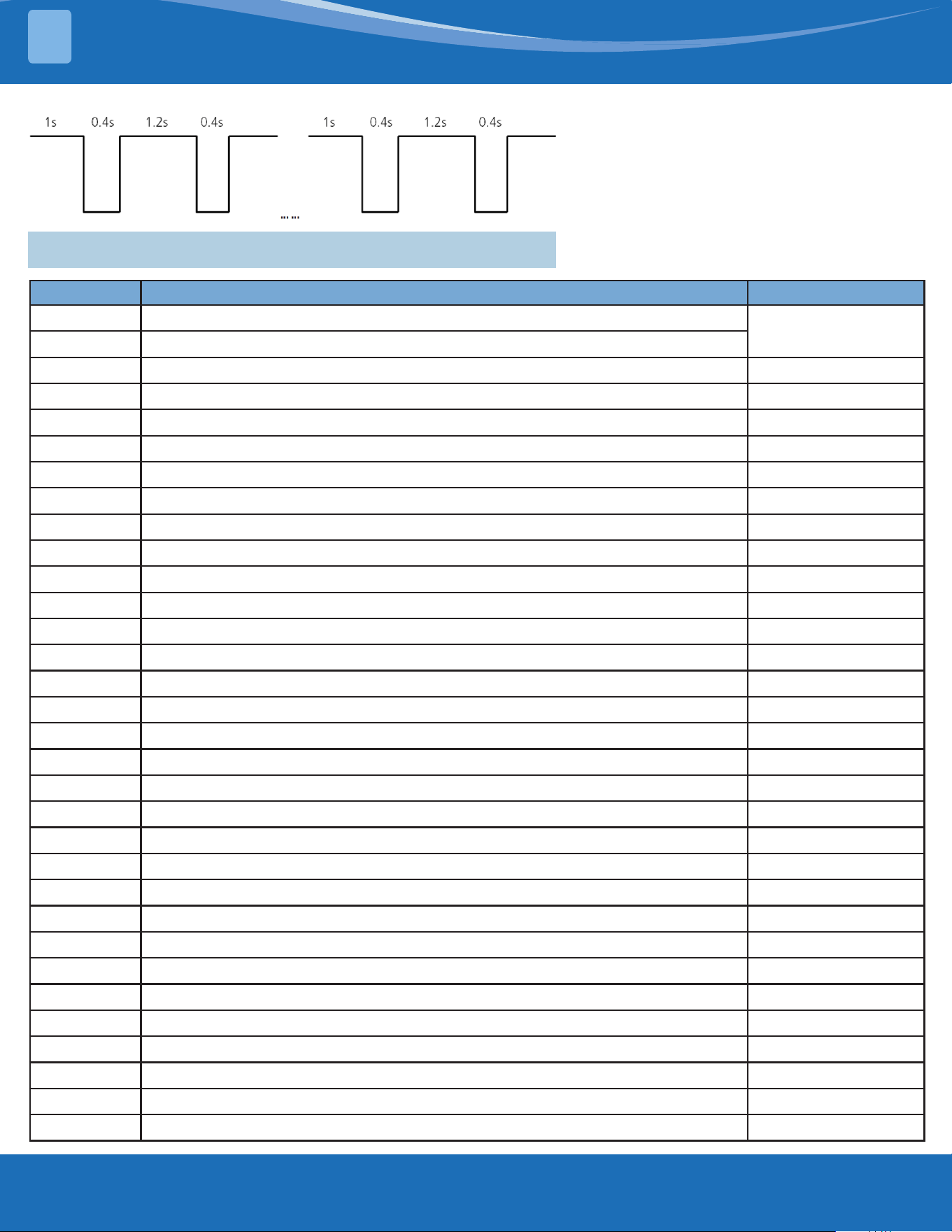
LED Flash Frequency:
4.3 Error Display (Outdoor Unit with Auxiliary Board)
Display Error Information Solution
DF
Defrost
Normal display, not
error code
FC
Forced cooling
EC 51
ODU EEPROM Parameter Error TS01-ODU
EL 01
IDU & ODU Communication Error TS02-S-INV
PC 40
Communication Error between Outdoor Main Chip & Compressor-Driven Chip TS31
PC 08
ODU Overcurrent Protection TS08-S
PC 10
ODU Low AC Voltage Protection TS10-S
PC 11
ODU Main Control Board DC Bus High Voltage Protection TS10-S
PC 12
ODU Main Control Board DC Bus Low Voltage Protection/341 MCE Error TS10-S
PC 00
ODU IPM Module Protection TS09-S
PC 0F
PFC Module Protection TS30
EC 71
Over Current Failure of ODU DC Fan Motor TS04-ODU
EC 72
Lack Phase Failure of ODU DC Fan Motor TS38
EC 07
ODU Fan Speed Out of Control TS04-ODU
PC 43
ODU Compressor Lack Phase Protection TS39
PC 44
ODU Zero Speed Protection TS08-S
PC 45
ODU IR Chip Drive Failure TS40
PC 46
Compressor Speed Out of Control TS08-S
PC 49
Compressor Overcurrent Failure TS08-S
PC 30
System High Pressure Protection TS26-INV
PC 31
System Low Pressure Protection TS26-INV
PC 0a
High Temperature Protection of Condenser TS27-INV
PC 06
Discharge Temperature Protection of Compressor TS32
LC 06
High Temperature Protection of Inverter Module (IPM) TS11-S-INV
PC 02
Compressor Top (or IPM) Temperature Protection TS11-S-INV
PH 90
High Temperature Protection of Evaporator --
PH 91
Low Temperature Protection of Evaporator --
EC 52
ODU Coil Temperature Sensor (T3) Error TS05-ODU
EC 53
ODU Ambient Temperature Sensor (T4) Error TS05-ODU
EC 54
Comp. Discharge Temperature Sensor (TP) Error TS05-ODU
EC 50
Open or Short Circuit of Outdoor Unit Temperature Sensor (T3, T4, TP) TS05-ODU
PC 0L
Low Ambient Temperature Protection LP
mrcool.com 38
38
4
4.4 Outdoor Unit Point Check Function
• A check switch is included on the auxiliary board.
• Press SW1 to check the unit's status while running. The digital display shows the following codes
each time the SW1 button is pushed.
Number of
Presses
Display Remark
00
Normal display Display running frequency, running state or malfunction code
01
Indoor unit capacity demand
code
S communication models display "--"
03
The frequency after the
capacity requirement transfer
04
The frequency after the
frequency limit
05
The frequency of sending to
341 chip
06
Indoor unit evaporator
temperature
If the temp. is lower than -9°C, the digital display tube will show "-9".
If the temp is higher than 70 degrees, the digital display tube will
show "70".
07
Condenser pipe temp. (T3)
08
Outdoor ambient temp. (T4)
09
Compressor discharge temp.
(TP)
The display value is between (0-199°C). If the temp. is lower than
(0°C) the digital display tube will show "0". If the temp. is higher than
99°C, light the decimal point of the high digit tube. (For example, the
digital display tube will show "0.5", so 0.5 multiplied by 10 to become
5, then added to 100 to become 105°C).
10
AD value of current
The display value is hex number.
For example, the digital display tube shows "Cd", so
C*161+d*160=12*16+13=205, it means AD value is 205.
11
AD value of voltage
12
Indoor unit running mode code
Standby:0, Cooling:1, Heating:2, Fan only:3, Drying:4, Forced
cooling:6, Defrosting:7
13
Outdoor unit running code
Standby:0, Cooling:1, Heating:2, Fan only:3, Drying:4, Forced
cooling:6, Defrosting:7
14
EXV open angle
Actual data/4.
If the value is higher than 99, light the decimal point of the high
digit tube. For example, the digital display tube show "2.0", so 2.0
multiplied by 10 to become 20, then added to 100 to become 120, it
means the EXV open angle is 120x4=480p.
15
Frequency limit symbol
Bit7 Frequency limit caused by IGBT radiator The display value
is hex number.
For example,
the digital
display tube
show 2A, the
corresponding
binary is 101010,
so Bit5=1, Bit3=1,
and Bit1=1
It means
frequency limit
caused by T2, T3,
and current
Bit6 Frequency limit caused by PFC
Bit5
Frequency limit caused by high
temperature of T2
Bit4
Frequency limit caused by low temperature
of T2
Bit3 Frequency limit caused by T3
Bit2 Frequency limit caused by TP
Bit1 Frequency limit caused by current
Bit0 Frequency limit caused by voltage
16
DC fan motor speed
0:o, 1:turbo, 2:high, 3:medium, 4:low, 5:breeze, 6:super breeze
7:other
TROUBLESHOOTING
mrcool.com39
TROUBLESHOOTING
4
Number of
Presses
Display Remark
17
IGBT radiator temp.
The display value is between 0-130 degrees. If the temp. is lower
than 0°C, the digital display tube will show "0". If the temp. is higher
tan 99 degrees, light the decimal point of the high digit tube. (For
example, the digital display tube show "0.5", so 0.5 multiplied by 10to
become 5, then added to 100 to become 105°C).
18
Indoor unit number The indoor unit can communicate with the outdoor unit well
19
Evaporator pip temp. T2 of 1#
indoor unit
S communication models display "--"
20
Evaporator pipe temp T2 of 2#
indoor unit
21
Evaporator pipe temp. T2 of 3#
indoor unit
22
1# Indoor unit capacity demand
code
23
2# Indoor unit capacity demand
code
24
3# Indoor unit capacity demand
code
25
Room temp. T1 of 1# indoor
unit
26
Room temp. T1 of 2# indoor
unit
27
Average room temp. T1
If the temp. is lower than 0 degrees, the digital display tube will show
"0". If the temp. is higher than 70 degrees, the digital display tube will
show "70". If the indoor unit is not connected, the digital display tube
will show "--"
28
Reason of stop
29
Evaporator pipe temp. sensor
T2B of 1# indoor unit
S communication models display "--"
30
Evaporator pipe temp. T2b of
2# indoor unit
mrcool.com 40
40
4
• To enter engineer mode, in power-on or standby mode, and in non-locked state, press the key
combination "ON/OFF+Air Speed" for 7S.
• After entering the engineer mode, the remote control will display icons of "Auto, Cool, Dry, Heat",
and he battery icon. At the same time it will also display the numeric code of the current engineer
mode (for the initial engineer mode, the numeric code displayed is 0), and all other icons are
inactive.
• In engineer mode, the value of the current numeric code can be adjusted circularly through the UP/
DOWN key, with the setting range of 0 to 30. Each time the current numeric code is adjusted, the
special code of the engineer mode will be transmitted with a delay of 0.6s. The code can also be
transmitted by pressing "OK", and the special code of the engineer mode sent contains information
of the currently displayed numeric code (if the numeric code is 0, the code to enter the engineer
mode will be transmitted).
• In engineer mode, other keys or operation are invalid except for the ON/OFF key, the UP/DOWN
key, the OK key or executing the operation to exit engineer mode.
Code Query Content Advanced Function Setting
0
Error code
Press "ON/OFF" for 2s to enter the capacity, the code displayed is
"Ch", press "OK" to send the query capacity code; press the UP/
DOWN key to select 1 to 100K
1
T1 temperature
Press "On/O" for 2s to enter the power down memory selector, the
code displayed is “Ch”, press "OK" to send the query power down
memory selector code; press the Up/Down key to select 1 or 0 and
press “OK” to conrm, 1 indicates that the power down memory
exists, and 0 indicates that no power down memory exists; and press
"On/O" for 2s to exit. (Set within 1 minute after power on).
2
T2 temperature
Press "On/O" for 2s to enter the Internal Fan Control Selector after
the pre-set temperature is reaches, the code displayed is “Ch”, press
"OK" to send the Query Internal Fan Control Selector code; press the
Up/Down key to select 1 to 13: 1 - Stop the fan, 2 - Min. fan speed,
3 - Set the air speed, 4 - Terminal stop for 4min running for 1min, 5 -
Terminal stop for 8min running for 1min, 6 - Terminal stop for 16min
running for 1min, 7 - Terminal stop for 24min running for 1min,
8 - Terminal stop for 48min running for 1min, 9 - Terminal stop for
15min running for 2.5min, 10 - Terminal stop for 30min running for
2.5min, 11 - Terminal stop for 60min running for 2.5min, 12- Set fan
speed (but stop the fan when the set fan speed is auto fan) and 13-
Breeze fan(but stop the fan when the set fan speed is auto fan) press
"OK" to conrm, and press "On/O" for 2s to exit.(Item 5~13 are valid
for some models)(Set within 1 minute after power on).
3
T3 temperature
Press "On/O" for 2s to enter the Mode Selector, press the Up/Down
key to select CH (cool and heat, Auto + Cool + Dry + Heat + Fan), HH
(Heat only, Heat only + Fan), CC(Cool only, Auto + Cool + Dry + Fa)
or nU (Cool and Heat without Auto, Cool + Dry + Heat + Fan), press
"OK" to conrm, and the mode selected can be memorized when
the remote control is powered down and powered on; and press
"On/O" for 2s to exit. When the remote control does not burn any
parameters, the mode setting will not be memorized.(CC or
nU is valid for some models)(Set within 1 minute after power on).
4
T4 temperature
Press the "On/O" for 2s to enter the Min. Set Temperature Selector,
press the Up/Down key to select "16°C~24°C", press "OK" to conrm,
and the Min. Set Temperature can be memorized when the remote
control is powered on and power lost; and press "On/O" for 2s to
exit. When the remote control does not burn any parameters, the
min. set temperature will not be memorized.(Set within 1 minute
after power on)
Outdoor Unit Point Check Function:
TROUBLESHOOTING
mrcool.com41
TROUBLESHOOTING
4
Code Query Content Advanced Function Setting
5
TP temperature
Press "On/O" for 2s to enter the Max. Set Temperature Selector,
press the Up/Down key to select "25°C~30°C", press "OK" to conrm,
and the Max. Set Temperature can be memorized when the remote
control is powered on and power lost; and press "On/O" for 2s to
exit. When the remote control does not burn any parameters, the
max. set temperature will not be memorized.(Set within 1 minute
after power on).
6
Compressor target frequency
FT
Press "On/O" for 2s to enter the Multi-split Cooling and Heating
Preference Selector, the code displayed is “Ch”, press "OK" to send
the Query Multi split Cooling and Heating Preference Selector code;
press the Up/Down key to select H (heating preferred), C (cooling
preferred) or A (master settings), press "OK" to conrm; and press
"On/O" for 2s to exit.(Set within 1 minute after power on)(Only
multi models are eective)
7
Compressor running frequency
Fr
/
8
/
10
/
11
Press "On/O" for 2S to enter the Min. Desired Cooling Frequency
Selector, the code displayed is Ch, press "OK" to send the Query Min.
Desired Cooling Frequency Selector code; press the Up/Down key
to select the minimum cooling frequency desired and press "OK" to
conrm; press "On/O" for 2s to exit.(Range:10-50Hz,--;”--” cancels
the Settings)(for some models) (Set within 1 minute after power on).
12
Set speed Pr of the outdoor fan
Press "On/O" for 2s to enter the Min. Desired Heating Frequency
Selector, the code displayed is “Ch”, press "OK" to send the Query
Min. Desired Heating Frequency Selector code; press the Up/Down
key to select the min. desired heating frequency value, press "OK" to
conrm; and press the "On/ O" for 2s to exit.(Range:10-50Hz,--;”--”
cancels the Settings) (for some models)(Set within 1 minute after
power on).
13
Opening Lr of EEV
Press "On/O" for 2s to enter the Max. Running Frequency Selector
of the restricted area 6 in the cooling mode T4, the code displayed is
“Ch”, press "OK" to send the Query Max. Running Frequency Selector
code of the restricted area 6 in the cooling mode T4; press the Up/
Down key to select the limit, then press "OK" to conrm; and press
"On/O" for 2s to exit. (Range:20-150Hz,--;”--” cancels the Settings)
(for some models).
14
Actual running speed ir of the
indoor fan
Press “On/O” for 2s to enter the Resonance Point Frequency
Selector, the code displayed is “Ch”, press “OK” to send the
Resonance Point Frequency Selector code; press the Up/Down key
to select the outdoor forced running frequency(“10-250Hz“), then
press “OK” to conrm; and press “On/O” for 2s to exit.(Range:10-
250Hz,--;”--” cancels the Settings)(for some models).
15
Indoor humidity Hu
Press "On/O" for 2s to enter the Outdoor Forced Running
Frequency Selector, the code displayed is “Ch”, press "OK" to send
the Query Outdoor Forced Running Frequency Selector code;
press the Up/Down key to select the outdoor forced running
frequency(“10-250Hz“), then press "OK" to conrm; and press "On/
O" for 2s to exit.(Range:10-250Hz,--;”--” cancels the Settings)(for
some models).
16
Set temperature TT after
compensation
Press "On/O" for 2s to enter One-Key Recovery, the code displayed
is “rS”, then press "OK" to send the One-Key Recovery code, the
mode selector of the remote control will recover to "Cooling and
heating", the min. temperature recovers to 16°C, and the max.
Temperature recovers to 30°C; and press "On/O" for 2s to exit.(for
some models).
mrcool.com 42
42
4
Code Query Content Advanced Function Setting
17
/ /
18
WIFI signal strength
Press “On/O” for 2s to enter Model Selection the code displayed is
“Ch”, then press “OK” to send the Model Selection code, press the
Up/Down key to select,such as 23,26,32,35,51,72,120 etc; and press
“On/O” for 2s to exit.
19
Dc bus voltage AD value
Press "On/O" for 2s to enter the Cooling Frequency Threshold
Settings; press the Up/Down key to select the cooling frequency
threshold, press "OK" to conrm; and press the "On/O" for 2s to
exit. (Range:40,41……83,84,--;”--” cancels the Settings)(Set within 1
minute after power on).
20
Indoor target frequency oT
Press "ON/OFF" for 2s to enter the Heating Frequency Threshold
Settings; press the Up/Down key to select the heating frequency
threshold, press "OK" to conrm; and press "On/O" for 2s to exit.
(Range:40,41……83,84,--;”--” cancels the Settings) (Set within 1 minute
after power on).
21
Reserve
Press "On/O" for 2s to enter the Cooling Temperature
Compensation Value Settings, the code displayed is “Ch”, then press
"OK" to send the Query Cooling Temperature Compensation Value
code; press the Up/Down key to select the cooling temperature
compensation value, then press "OK"; and press "On/O" for 2s to
exit.(Rage:-3.0,-2.5,-2.0…2.0,2.5,3.0,3.5,--;”--” cancels the Settings).
22
Press "On/O" for 2s to enter the Heating Temperature
Compensation Value Settings, the code displayed is “Ch”, press
"OK" to send the Query Heating Temperature Compensation Value
code; press the Up/Down key to select the heating temperature
compensation value, then press "OK"; and press "On/O" for 2s
to exit.(Range:-6.5,-6,…1.0,1.5,2.0…6.0,6.5,7.0,7.5,--;”--” cancels the
Settings).
23
Press "On/O" for 2s to enter the Max. Cooling Air Speed Settings,
the code displayed is “Ch”, press "OK" to send the Query Max.
Cooling Air Speed code; press the Up/Down key to select the max.
cooling air speed, then press "OK"; and press "On O" for 2s to exit.
(Range: -41,-40,-39…17,18,19,20,-- ;”--” cancels the Settings).
24
Press "On/O" for 2S to enter the Min. Cooling Air Speed Settings,
the code displayed is "Ch", press "OK" to send the Query Min. Cooling
Air Speed code; press the Up/Down key to select the minimum
cooling air speed and press "OK" to conrm; press "On/O" for 2s to
exit.(Range: -41,-40,-39… 17,18,19,20,--;”--” cancels the Settings).
25
Press "On/O" for 2s to enter the Max. Heating Air Speed Settings,
the code displayed is "Ch", press "OK" to send the Query Max.
Heating Air Speed code; press the Up/Down key to select the
maximum heating air speed and press "OK" to conrm; press "On/
O" for 2s to exit.(Range: -41,-40,-39… 17,18,19,20,--;”--” cancels the
Settings).
26
Press "On/O" for 2s to enter the Min. Heating Air Speed Settings,
the code displayed is "Ch", press "OK" to send the Query Min.
Heating Air Speed code; press the Up/Down key to select the
minimum heating air speed and press "OK" to conrm; press "On/
O" for 2s to exit.(Range: -41,-40,-39…17,18,19,20,--;”--” cancels the
Settings).
27
/
28
Press “On/O” for 2s to enter the The Temperature of Stop Fan, the
code displayed is “Ch”, press “OK” to send the The Temperature of
Stop Fan code; press the Up/Down key to select 16,17,18...28 and
press “OK” to conrm; press “On/O” for 2s to exit.
29
30
TROUBLESHOOTING
mrcool.com43
TROUBLESHOOTING
4
• In channel 1-30 settings of the engineer mode, long press the on/o key to return the previous
engineer mode.
• When the setting is successful, "CS" will be displayed; When the setting fails, "CF" will be displayed.
Exit of engineer mode:
1. In engineer mode, press the key combination of "On/O+Air speed" for 2s.
2. The engineer mode will be exited if there are no valid key operation for continuous 60s.
Error Code of Engineer Mode:
Display Error Information
Na
No fault or protection
EH 00
IDU EEPROM malfunction
EH 0A
Indoor EEPROM parameter error
EL 01
IDU & ODU communication error
EH bA
Communication error between indoor unit and indoor external fan module
EH 30
Parameters error of indoor external fan
EH 35
Phase failure of indoor external fan
EH 36
Indoor external fan current sampling bias fault
EH 37
Indoor external fan zero speed failure
EH 38
Indoor external fan stall failure
EH 39
Out of sep failure of indoor external fan
EH 3A
Low voltage protection of indoor external fan DC bus
EH 3b
Indoor external fan DC bus voltage is too high fault
EH 3E
Indoor external fan overcurrent fault
EH 3F
Indoor external fan module protection/hardware overcurrent protection
EH 03
IDU fan speed out of control
EC 51
ODU EEPROM parameter error
EC 52
ODU coil temp. sensor (T3) error
EC 53
ODU ambient temp. sensor (T4) error
EC 54
COMP. Discharge temp. sensor (TP) error
EC 55
ODU IPM module temp. sensor (TH) error
EC 0d
Outdoor unit malfunction
EH 60
IDU room temp. sensor (T1) error
EH 61
Evaporator coil temperature sensor T2 is in open circuit or short circuit
EC 71
Outdoor external fan overcurrent fault
EC 75
Outdoor external fan module protection/hardware overcurrent protection
EC 72
Outdoor external fan phase failure
EC 74
Outdoor external fan current sampling bias fault
EC 73
Zero speed failure of outdoor unit DC fan
EC 07
ODU fan speed out of control
EL OC
System lacks refrigerant
mrcool.com 44
44
4
Display Error Information
PC 00
ODU IPM module protection
PC 10
ODU low AC voltage protection
PC 11
ODU main control board DC bus high voltage protection
PC 12
ODU main control board DC bus low voltage protection/341 MCE error
PC 02
Compressor top (or IPM) temp. protection
PC 40
Communication error between outdoor main chip and compressor driven chip
PC 41
Compressor current sampling circuit failure
PC 42
Compressor start failure
PC 43
ODU compressor lack phase protection
PC 44
ODU zero speed protection
PC 45
ODU IR chip drive failure
PC 46
Compressor speed has been out of control
PC 49
Compressor overcurrent failure
PC 06
Discharge temperature protection of compressor
PC 08
ODU current protection
PH 09
Anti-cold air in heating mode
PC 0F
PFC module protection
PC 30
System overpressure protection
PC 31
System pressure is too low protection
PC 03
Pressure protection (low or high pressure)
PC 0L
Outdoor low temp. protection
PH 90
Low temperature protection of evaporator
PH 91
Low temperature protection of evaporator
PC 0A
High temperature protection of condenser
PH 0C
Indoor unit humidity sensor malfunction
LH 00
Evaporator temp. freq.limited
LH 30
Indoor external fan current freq. limited
LH 31
Indoor external fan voltage freq. limited
LC 01
Condenser coil temp. (T3) freq. limited
LC 02
Current freq. limited
LC 05
Voltage freq. limited
LC 03
Current freq. limited
LC 06
IPM module temp. freq. limited
LC 30
High pressure freq. limited
LC 31
Low pressure freq. limited
LH 07
Remote control frequency limitation in eect
--
IDUs mode conict (multi-zone)
TROUBLESHOOTING
mrcool.com45
TROUBLESHOOTING
4
4.5 Error Diagnosis Without Error Code
Remote Maintenance:
Suggestion: When troubles occur, please check the following points with the customer before eld maintenance.
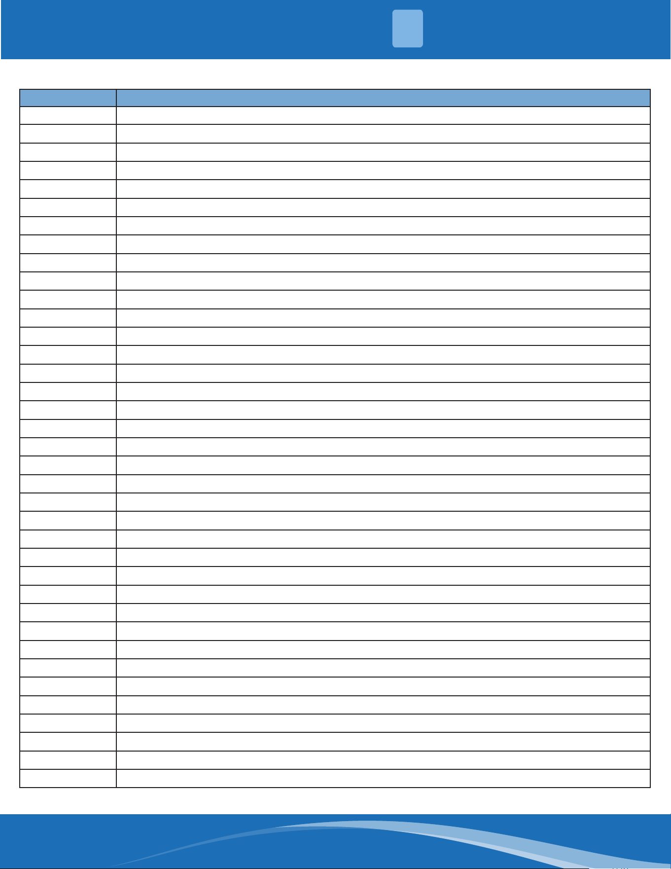
No. Problem Solution
1
Unit will not start TS17-TS18
2
The power switch is on but fans will not start TS17-TS18
3
The temperature on the display board cannot be set TS17-TS18
4
Unit is on but the air is not cold/hot TS17-TS18
5
Unit runs but shortly stops TS17-TS18
6
The unit starts up and stops frequently TS17-TS18
7
Unit runs continuously but insucient cooling/heating TS17-TS18
8
Cool cannot change to heat TS17-TS-18
9
Unit is noisy TS17-TS18
Field Maintenance:
No. Problem Solution
1
Unit will not start TS19-TS20
2
Compressor will not start but fans run TS19-TS20
3
Compressor and condenser fan will not start TS19-TS-20
4
Air handler fan will not start TS19-TS20
5
Condenser fan will not start TS19-TS20
6
Unit runs but shortly stops TS19-TS20
7
Compressor short-cycles due to overload TS19-TS20
8
High suction pressure TS19-TS20
9
Low discharge pressure TS19-TS20
10
High suction pressure TS19-TS20
11
Low suction pressure TS19-TS20
12
Unit runs continuously but insucient cooling TS19-TS20
13
Too cool TS19-TS20
14
Compressor is noisy TS19-TS20
15
Horizontal louver cannot revolve TS19-TS20
mrcool.com 46
46
4
1. Remote
Maintenance
Electrical Circuit Refrigerant Circuit
Possible causes of
trouble
Power failure
The main power tripped
Loose connections
Faulty transformer
The voltage too high or too low
The remote control is powered o
Broken the remote control
Dirty air lter
Dirty condenser ns
The setting temperature is higher/lower
than the room's(cooling/heating)
The ambient temperature is too high/
low when the mode is cooling/heating
Fan mode
Silence function is activate
Frosting and defrosting frequency
Unit will not start √ √ √ √ X X X X X X X X X X
The power switch is
on but fans will not
start
X X √ √ √ X X X X X X X X X
The temperature
on the playboard
cannot be set
X X X X X √ √ X X X X X X X
Unit is on but the air
is not cold/hot
X X X X X X X X X √ √ √ X X
Unit runs but shortly
stops
X X X X √ X X X √ √ X X X
The unit startup and
stops frequently
X X X X √ X X X X X √ X X √
Unit runs
continuously but
insucient cooling/
heating
X X X X X X X √ √ √ √ X √ X
Cool cannot change
to heat
X X X X X X X X X X X X X X
Unit is noisy X X X X X X X X X X X X X X
Test method/
remedy
Test voltage
Close the power switch
Inspect connections - tighten
Change the transformer
Test voltage
Replace the battery of the
remote control
Replace the remote control
Clean or replace
Clean
Adjust the setting temperature
Turn on the unit later
Adjust to cool mode
Turn o the silence function
Turn on the unit later
TROUBLESHOOTING
mrcool.com47
TROUBLESHOOTING
4
1. Remote
Maintenance
Others
Possible causes of
trouble
Heavy load condition
Loosen hold down bolts or screws
Bad airproof
The air inlet or outlet of either unit is
blocked
Interference from cell phone towers and
remote boosters
Shipping plates remain attached
Unit will not start X X X X X X
The power switch is
on but fans will not
start
X X X X √ X
The temperature
on the playboard
cannot be set
X X X X X X
Unit is on but the air
is not cold/hot
X X X X X X
Unit runs but shortly
stops
X X X X X X
The unit startup and
stops frequently
X X X √ X X
Unit runs
continuously but
insucient cooling/
heating
√ X √ √ X X
Cool cannot change
to heat
X X X X X X
Unit is noisy X √ X X X √
Test method/
remedy
Check heat load
Tighten bolts and screws
Close all windows and doors
Remove the obstacles
Reconnect the power or press
ON/OFF button on the remote to
restart operation
Remove item
mrcool.com 48
4
2. Field
Maintenance
Refrigerant Circuit Others
Possible
causes of
trouble
Compressor stuck
Shortage of refrigerant
Restricted liquid line
Dirty air lter
Dirty evaporator coil
Insucient air through
evaporator coil
Overcharge of refrigerant
Dirty or partially blocked
condenser
Air or incompressible gas in
refrigerant cycle
Short cycling of condensing air
High temperature condensing
medium
Insucient condensing medium
Broken compressor internal parts
Inecient compressor
Expansion valve obstructed
Expansion valve or capillary tube
close completely
Leaking power element on
expansion valve
Poor installation of feeler bulb
Heavy load condition
Loosen hold down bolts and/or
screws
Shipping plates remain attached
Poor choices of capacity
Contact of piping with other
piping or external plate
Unit will not
start
X X X X X X X X X X X X X X X X X X X X X X X
Compressor
will not start
but fans run
√ X X X X X X X X X X X X X X X X X X X X X X
Compressor
and condenser
fan will not
start
X X X X X X X X X X X X X X X X X X X X X X X
Air handler fan
will not start
X X X X X X X X X X X X X X X X X X X X X X X
Condenser fan
will not start
X X X X X X X X X X X X X X X X X X X X X X X
Unit runs but
shortly stops
X √ √ X X X √ √ X X X X X X X √ √ X X X X X X
Compressor
short-cycles
due to overload
X √ X X X X √ √ X X X X X X X X X X X X X X X
High discharge
pressure
X X X X X X √ √ √ √ √ √ X X X X X X X X X X X
Low discharge
pressure
X √ X X X X X X X X X X X √ X X X X X X X X X
Test method/
remedy
Replace the compressor
Leak test
Replace restricted part
Clean or replace
Clean coil
Check fan
Change charged refrigerant
volume
Clean condenser or remove
obstacle
Purge, evacuate and recharge
Remove obstruction to air ow
Remove obstruction in air or
water ow
Remove obstruction in air or
water ow
Replace compressor
Test compressor eciency
Replace valve
Replace valve
Replace valve
Fix feeler bulb
Check heat load
Tighten bolts or screws
Remove them
Choose system of larger capacity
or add another system
Rectify piping so as to not contact
with each other or with external
plate
TROUBLESHOOTING
mrcool.com49
TROUBLESHOOTING
2. Field
Maintenance
Refrigerant Circuit Others
Possible causes of
trouble
Compressor stuck
Shortage of refrigerant
Restricted liquid line
Dirty air lter
Dirty evaporator coil
Insucient air through evaporator
coil
Overcharge of refrigerant
Dirty or partially blocked condenser
Air or incompressible gas in
refrigerant cycle
Short cycling of condensing air
High temperature condensing
medium
Insucient condensing medium
Broken compressor internal parts
Inecient compressor
Expansion valve obstructed
Expansion valve or capillary tube
close completely
Leaking power element on
expansion valve
Poor installation of feeler bulb
Heavy load condition
Loosen hold down bolts and/or
screws
Shipping plates remain attached
Poor choices of capacity
Contact of piping with other piping
or external plate
High suction
pressure
X X X X X X √ X X X X X X √ X X X √ √ X X X X
Low suction
pressure
X √ √ √ √ √ X X X X X X X X √ √ √ X X X X X X
Unit runs
continuously but
insucient cooling
X √ √ √ √ √ X √ √ √ X X X √ X X X X √ X X √ X
Too Cool X X X X X X X X X X X X X X X X X X X X X X X
Compressor is
noisy
X X X X X X √ X X X X X √ X X X X X X √ √ X √
Horizontal louver
cannot revolve
X X X X X X X X X X X X X X X X X X X X X X X
Test method/
remedy
Replace the compressor
Leak test
Replace restricted part
Clean or replace
Clean coil
Check fan
Change charged refrigerant volume
Clean condenser or remove obstacle
Purge, evacuate and recharge
Remove obstruction to air ow
Remove obstruction in air or water ow
Remove obstruction in air or water ow
Replace compressor
Test compressor eciency
Replace valve
Replace valve
Replace valve
Fix feeler bulb
Check heat load
Tighten bolts or screws
Remove them
Choose system of larger capacity or add
another system
Rectify piping so as to not contact with
each other or with external plate
4
mrcool.com 50
2. Field
Maintenance
Electrical Circuit
Possible causes of
trouble
Power Failure
Blown fuse or varistor
Loose connections
Shorted or broken wires
Safety device opens
Faulty thermostat/room
temperature sensor
Wrong setting place of
temperature sensor
Faulty transformer
Shorted or open capacitor
Faulty magnetic contactor for
compressor
Faulty magnetic contactor for fan
Low voltage
Faulty stepping motor
Shorted or grounded compressor
Shorted or grounded fan motor
Unit will not start √ √ √ √ √ X X √ X X X X X X X
Compressor will
not start but fans
run
X X X √ X √ X √ √ X X X X √ X
Compressor and
condenser fan will
not start
X X X √ X √ X X X √ X X X X X
Air handler fan will
not start
X X X √ X X X X √ X √ X X X √
Condenser fan will
not start
X X X √ X √ X X √ X √ X X X √
Unit runs but
shortly stops
X X X X X X X X X √ X √ X X X
Compressor
short-cycles due to
overload
X X X X X X X X X √ X √ X X X
High discharge
pressure
X X X X X X X X X X X X X X X
Low discharge
pressure
X X X X X X X X X X X X X X X
Test method/
remedy
Test voltage
Inspect fuse type & size
Inspect connections - tighten
Test circuits with tester
Test continuity of safety device
Test continuity of thermostat/ sensor
& wiring
Place the temperature sensor at the
central of the air inlet grille
Check control circuit with tester
Check capacitor with tester
Test continuity of coil & contacts
Test continuity of coil & contacts
Test voltage
Replace the stepping motor
Check resistance with multimeter
Check resistance with multimeter
4
TROUBLESHOOTING
mrcool.com51
TROUBLESHOOTING
2. Field
Maintenance
Electrical Circuit
Possible causes of
trouble
Power Failure
Blown fuse or varistor
Loose connections
Shorted or broken wires
Safety device opens
Faulty thermostat/room
temperature sensor
Wrong setting place of temperature
sensor
Faulty transformer
Shorted or open capacitor
Faulty magnetic contactor for
compressor
Faulty magnetic contactor for fan
Low voltage
Faulty stepping motor
Shorted or grounded compressor
Shorted or grounded fan motor
High suction
pressure
X X X X X X X X X X X X X X X
Low suction
pressure
X X X X X X X X X X X X X X X
Unit runs
continuously but
insucient cooling
X X X X X X X X X X X X X X X
Too cool X X X X X X √ √ X X X X X X X
Compressor is
noisy
X X X X X X X X X X X X X X X
Horizontal louver
can not revolve
X X √ √ X X X X X X X X √ X X
Test method/
remedy
Test voltage
Inspect fuse type & size
Inspect connections - tighten
Test circuits with tester
Test continuity of safety device
Test continuity of thermostat/ sensor
& wiring
Place the temperature sensor at the
central of the air inlet grille
Check control circuit with tester
Check capacitor with tester
Test continuity of coil & contacts
Test continuity of coil & contacts
Test voltage
Replace the stepping motor
Check resistance with multimeter
Check resistance with multimeter
4
mrcool.com 52
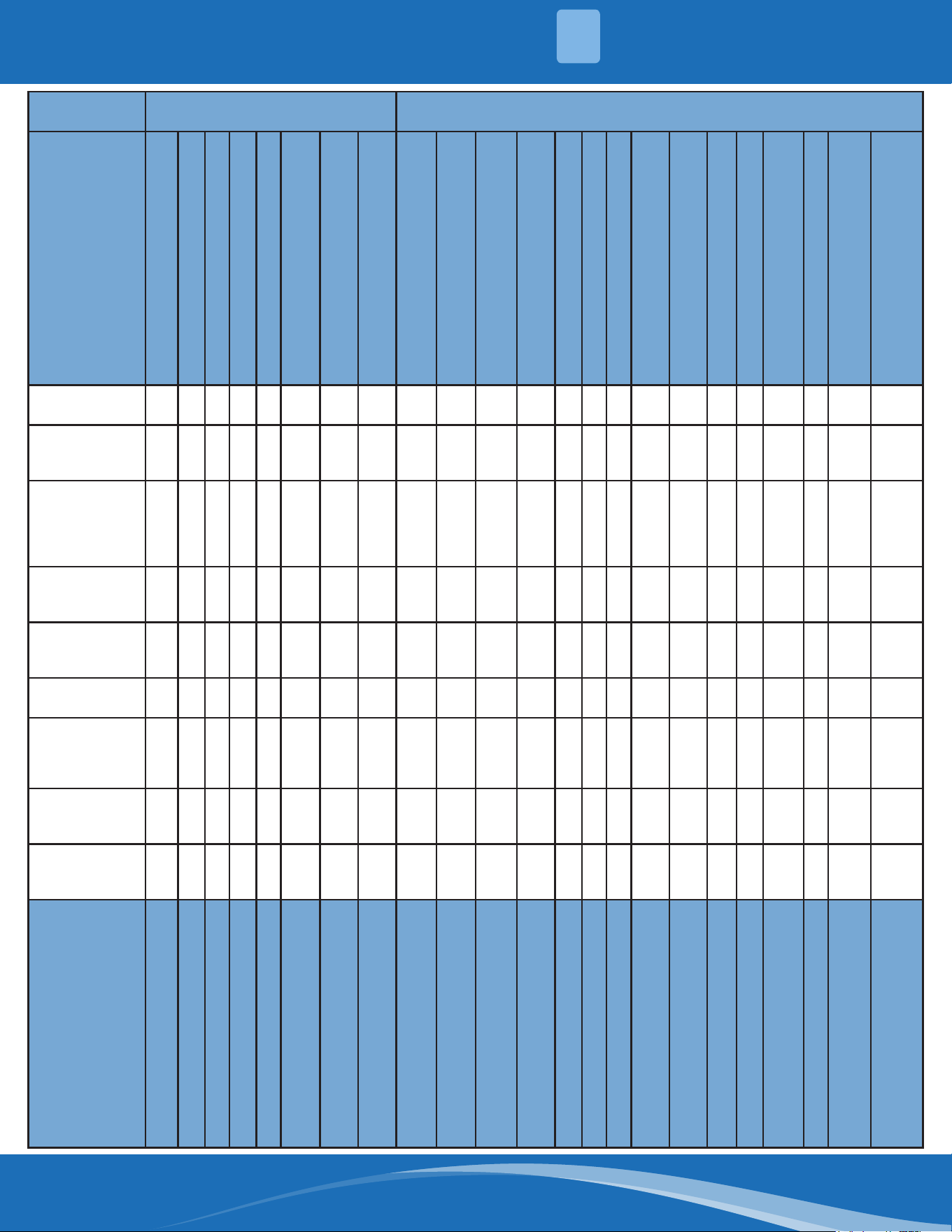
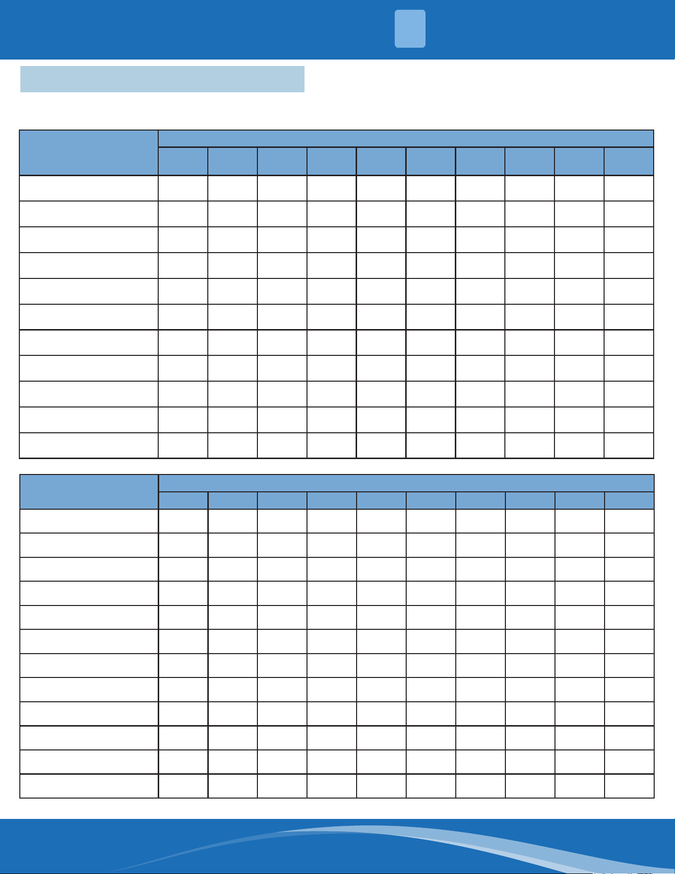
4.6 Quick Maintenance by Error Code
If you do not have the time to test which specic parts are faulty, you can change the required parts according to
the error code. You can nd the parts to replace by error code in the following table.
Part Requiring
Replacement
Error Code
EH 00/
EH 0A
EL 01 EH 02 Eh 03 EH 60 EH 61 EH 0B EL 0C EC 56 FH CC
Indoor PCB
√ √ √ √ √ √ √ √
X
√
Outdoor PCB
X
√
X X X X X X
√
X
Display Board
X X X X X X
√
X X X
Indoor Fan Motor
X X X
√
X X X X X X
T1 Sensor
X X X X
√
X X X X X
T2 Sensor
X X X X X
√
X
√
X X
T2B Sensor
X X X X X X X X
√
X
Refrigerant Sensor
X X X X X X X X X
√
Reactor
X
√
X X X X X X X X
Compressor
X X X X X X X X X
√
Additional Refrigerant
X X X X X X X
√
X X
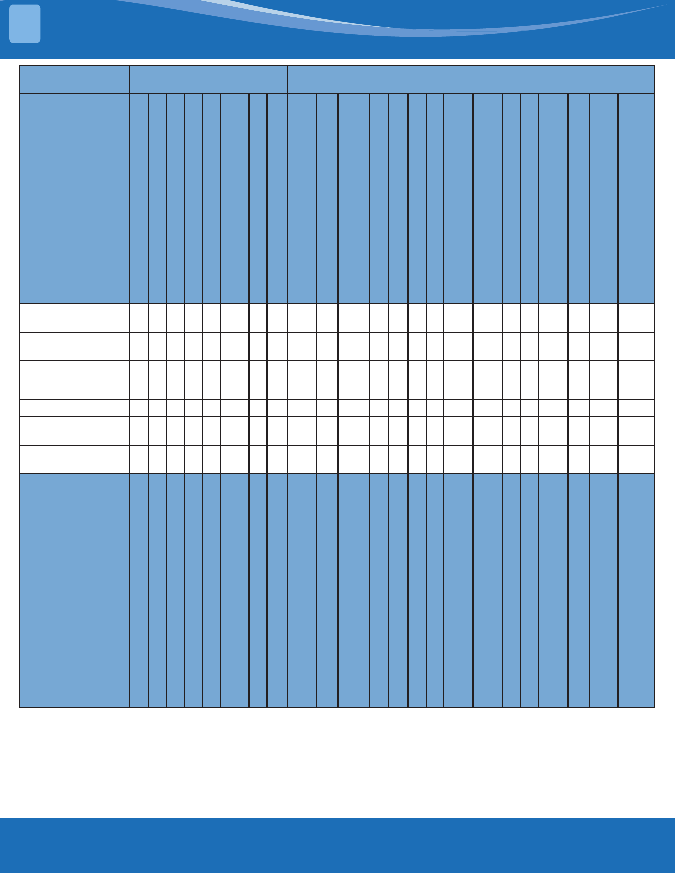
Part Requiring
Replacement
Error Code
EC 53 EC 52 EC 54 EC 51 EC 07 PC 00 PC 01 PC 02 PC 03 PC 04
Outdoor PCB
√ √ √ √ √ √ √ √ √ √
Indoor Fan Motor
X X X X X X X X X X
Outdoor Fan Motor
X X X X
√ √
X
√
X
√
T3 Sensor
X
√
X X X X X X X X
T4 Sensor
√
X X X X X X X X X
TP Sensor
X X
√
X X X X X X X
Reactor
X X X X X X
√
X X X
Compressor
X X X X X
√
X X X
√
IPM Module Board
X X X X X
√ √ √
X
√
High Pressure Protector
X X X X X X X
√
X X
Low Pressure Protector
X X X X X X X X
√
X
Additional Refrigerant
X X X X X X X X
√
X
4
TROUBLESHOOTING
mrcool.com53
TROUBLESHOOTING
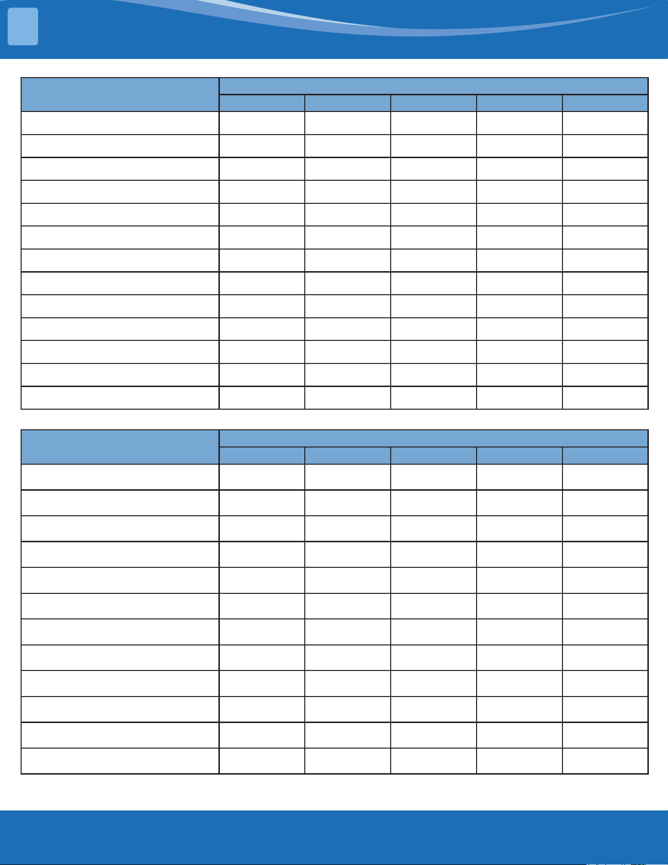
Part Requiring Replacement
Error Code
PC 06 PC 08/44/49 PC 0A PC OF PC 40
Outdoor PCB
√ √ √ √ √
Outdoor Fan Motor
X
√ √
X X
T3 Sensor
X X
√
X X
TP Sensor
√
X X X X
Pressure Sensor
X X X X X
Reactor
X
√
X
√
X
Compressor
X X X X X
IPM Module Board
X
√
X X
√
High Pressure Valve Assembly
√
X X X X
High Pressure Protector
X X X X X
Low Pressure Protector
X X X X X
Additional Refrigerant
√
X
√
X X
Electric Control Box
X X X X
√
Part Requiring Replacement
Error Code
PC 41 PC 43 PC 10/11/12 PC 30 PC 31
Outdoor PCB
√ √ √ √ √
Outdoor Fan Motor
X X X
√
X
T3 Sensor
X X X X X
TP Sensor
X X X X X
Pressure Sensor
X X X X X
Reactor
X X
√
X X
Compressor
X
√
X X X
IPM Module Board
X X
√
X X
High Pressure Valve Assembly
X X X X X
High Pressure Protector
X X X
√
X
Low Pressure Protector
X X X X
√
Additional Refrigerant
X X X X
√
4
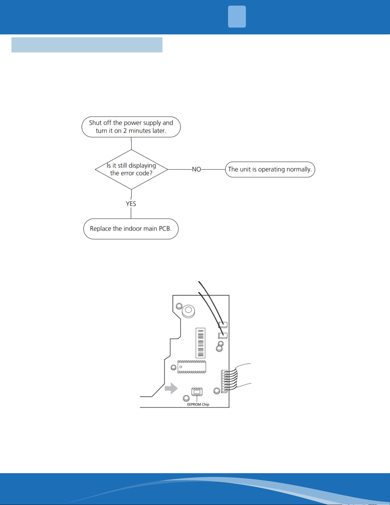
mrcool.com 54
4.7 Troubleshooting by Error Code
TS01-IDU: IDU EEPROM malfunction or indoor EEPROM parameter error diagnosis
and solution.
Description: Indoor PCB main chip does not receive feedback from EEPROM chip.
Recommended parts to prepare:
• Indoor PCB
Troubleshooting and repair:
Remarks:
EEPROM: A read-only memory whose contents can be erased and reprogrammed using a puled
voltage. The location of the EEPROM chip on the indoor PCB is shown in the following image:
Note: These pictures are for reference, actual appearance may vary.
4
TROUBLESHOOTING
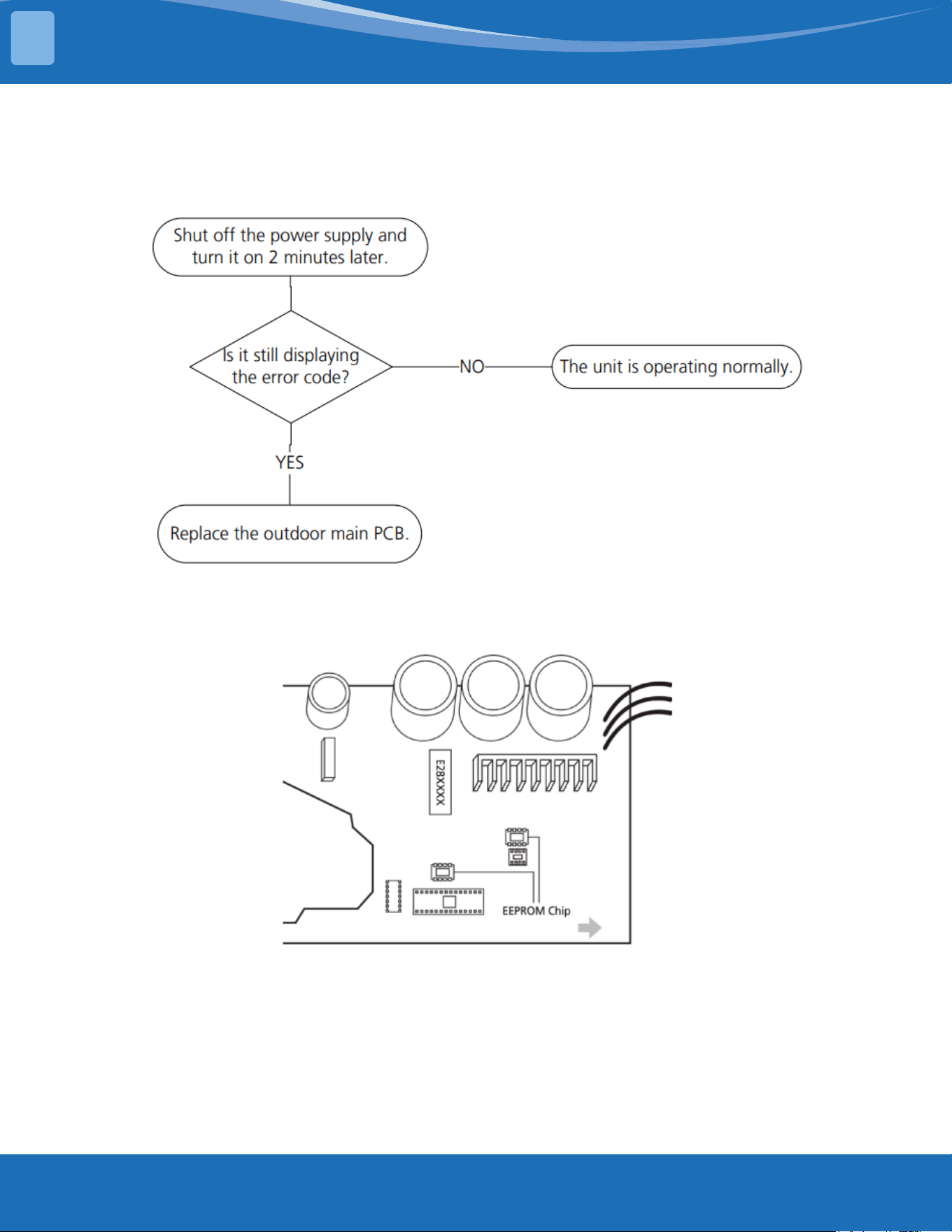
mrcool.com55
TROUBLESHOOTING
TS01-ODU: ODU EEPROM parameter error diagnosis and solution
Description: Outdoor PCB main chip does not receive feedback from EEPROM chip.
Recommended parts to prepare:
• Outdoor PCB
Troubleshooting and repair:
Remarks:
EEPROM: A read-only memory whose contents can be erased and reprogrammed using a puled
voltage. The location of the EEPROM chip on the outdoor PCB is shown in the following image:
Note: This picture is for reference only, actual appearance may vary.
4
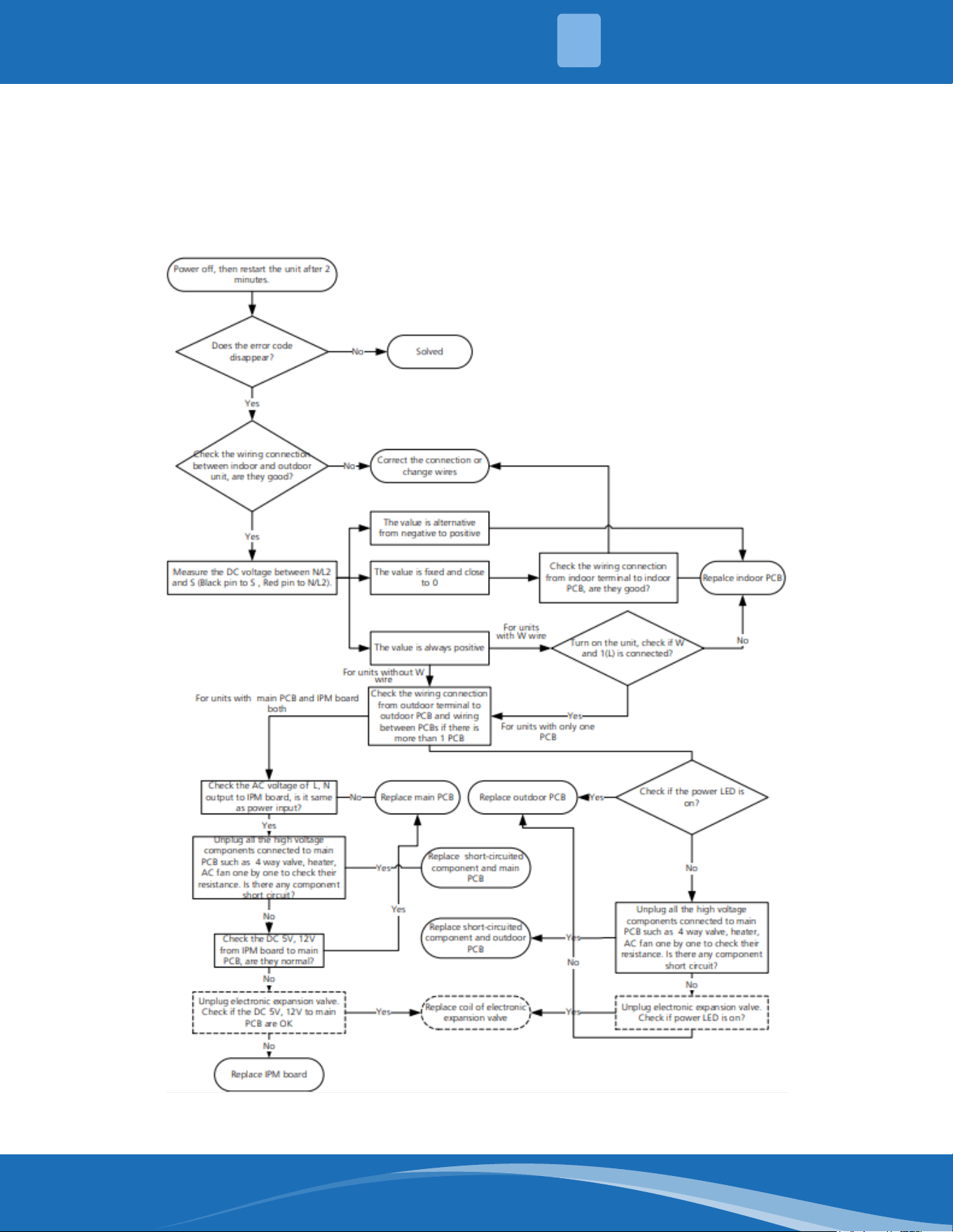
mrcool.com 56
TS02-S-INV: IDU & ODU communication error diagnosis and solution
Description: Indoor unit can not communicate with outdoor unit
Recommended parts to prepare:
• Indoor PCB
• Outdoor PCB
• Short-circuited component
Troubleshooting and repair:
4
TROUBLESHOOTING
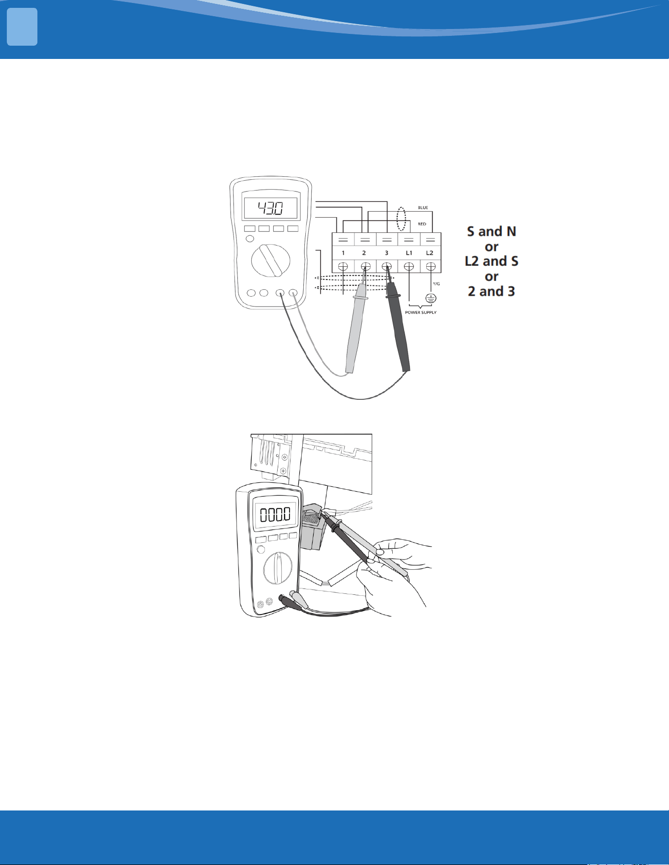
mrcool.com57
TROUBLESHOOTING
Remarks:
• Use a multimeter to test the DC voltage between 2 port (or S or L2 port) and 3 port (or N or S port)
of outdoor unit. The red pin of the multimeter connects with 2 port (or S or L2 port) while the black
pin is for 3 port (or N or S port).
• When AC is running normal the voltage will move alternately between -25V to 25V.
• If the outdoor unit has a malfunction, the voltage will alternate with a positive value.
• If the indoor unit has a malfunction the voltage will be a certain value.
• Use a multimeter to test the resistance of the reactor which does not connect with the capacitor.
• The normal value should be around zero ohms. Otherwise the reactor has a malfunction.
Note: The pictures and the values are for reference only, actual condition and specic values may vary.
4
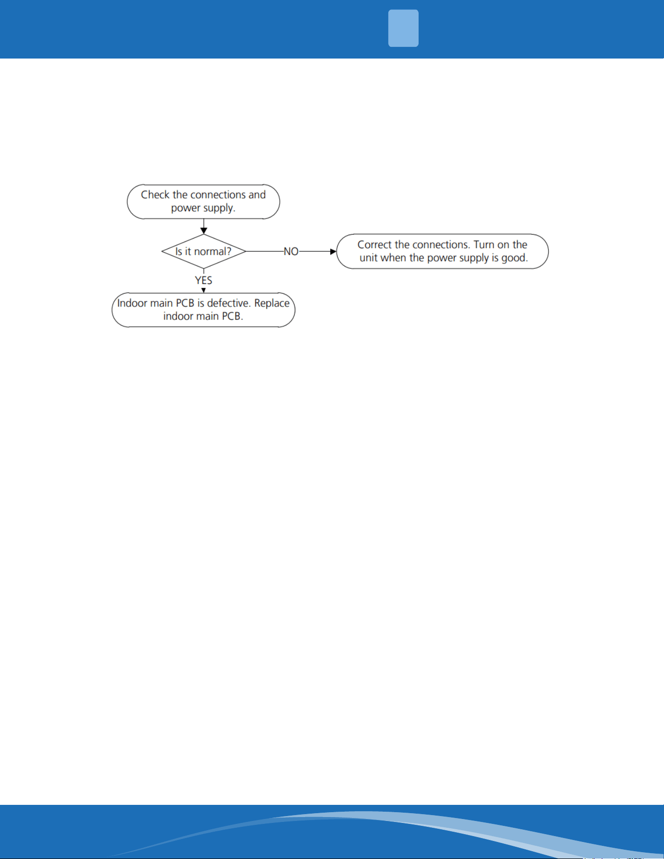
mrcool.com 58
TS03: Zero crossing detection error diagnosis and solution
Description: When PCB does not receive zero crossing signal feedback for 4 minutes or the zero
crossing signal time interval is abnormal.
Recommended parts to prepare:
• Connection wires
• Indoor main PCB
Troubleshooting and repair:
Note: Zero crossing detection error is only valid for the unit with AC fan motor, for other models, this
error is invalid.
4
TROUBLESHOOTING
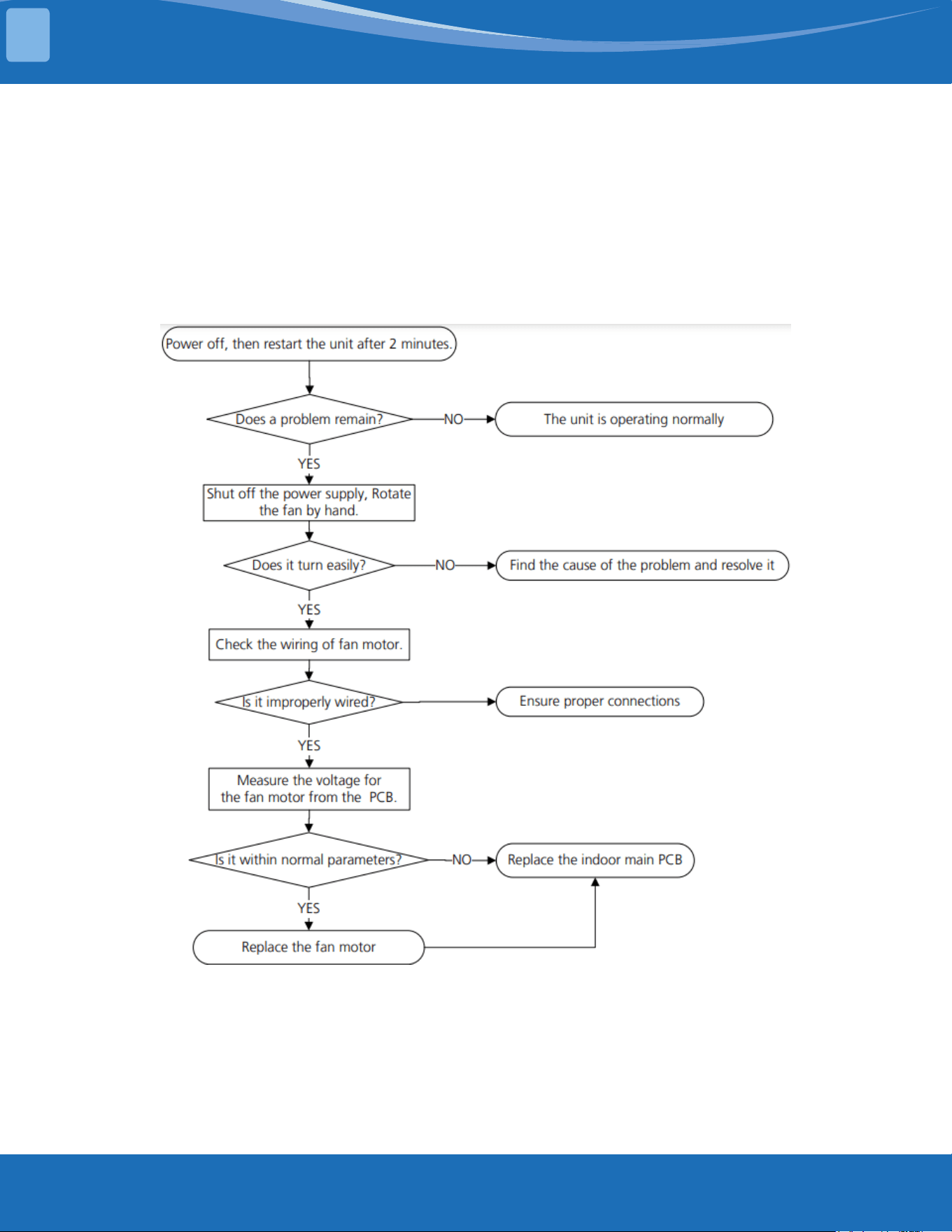
mrcool.com59
TROUBLESHOOTING
TS04-S-IDU: The indoor fan speed is operating outside of normal range diagnosis
and solution
Description: When the indoor fan speed keeps too low or too high for a period of time the LED
displays the failure code and the AC turns o.
Recommended parts to prepare:
• Connection wires
• Fan assembly
• Fan motor
• Indoor main PCB
Troubleshooting and repair:
4
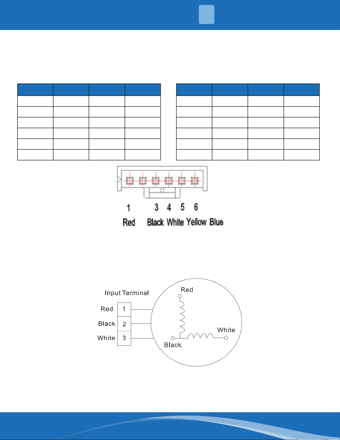
mrcool.com 60
Index:
1. Indoor or Outdoor DC fan motor (control chip is in fan motor)
Power on and make sure the unit is in standby, measure the voltage of pin1-pin3, pin4-pin3 on the fan
motor connector. If the value of the voltage is not in the range showing in the tables below the PCB
will have problems and will need to be replaced.
NO. Color Signal Voltage
1 Red Vs/Vm 192V~380V
2 --- --- ---
3 Black GND 0V
4 White Vcc 14-17.5V
5 Yellow Vsp 0~5.6V
6 Blue FG 14-17.5V
DC motor voltage input and output (voltage: 220-240V~) DC motor voltage input and output (voltage: 115V~)
NO. Color Signal Voltage
1 Red Vs/Vm 140V~190V
2 --- --- ---
3 Black GND 0V
4 White Vcc 14-17.5V
5 Yellow Vsp 0~5.6V
6 Blue FG 14-17.5V
2. Indoor AC Motor
Power on and set the unit running in fan mode at high fan speed. After running for 15 seconds,
measure the voltage of pin1 and pin2. If the value of the voltage is less than 100V(208~240V power
supply) or 50V (115V power supply) the PCB has problems and will need to be replaced.
4
TROUBLESHOOTING
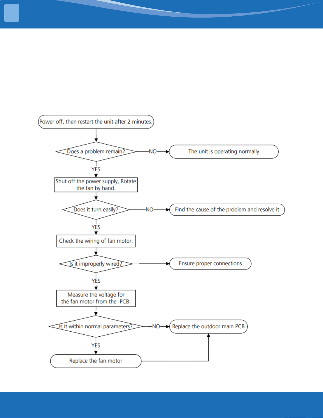
mrcool.com61
TROUBLESHOOTING
TS04-ODU: The outdoor fan speed is operating outside of normal range diagnosis
and solution
Description: When the outdoor fan speed keeps too low or too high for a certain time, the LED
displays the failure code and the system turns o.
Recommended parts to prepare:
• Connection wires
• Fan assembly
• Fan motor
• Outdoor main PCB
Troubleshooting and repair:
4
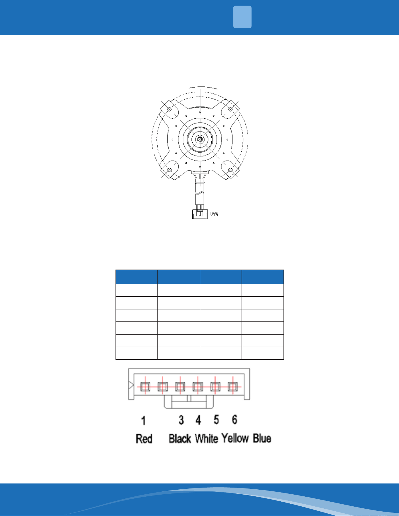
mrcool.com 62
Index:
1. Outdoor DC fan motor (control chip is in outdoor PCB)
Release the UVW connector and measure the resistance of U-V, U-W, V-W. If the resistance is not equal
to each other the fan motor has a problem and needs to be replaced. Otherwise the PCB has a
problem and needs to be replaced.
2. DC fan motor (control chip is in fan motor, single fan)
Power on and when the unit is in standby measure the voltage of pin1-pin3, pin4-pin3 in the fan
motor connector. If the value of the voltage is not in the range showing in below table the PCB has
a problem and needs to be replaced.
NO. Color Signal Voltage
1 Red Vs/Vm 192V~380V
2 --- --- ---
3 Black GND 0V
4 White Vcc 13.5-16.5V
5 Yellow Vsp 0~6.5V
6 Blue FG 13.5-16.5V
4
TROUBLESHOOTING
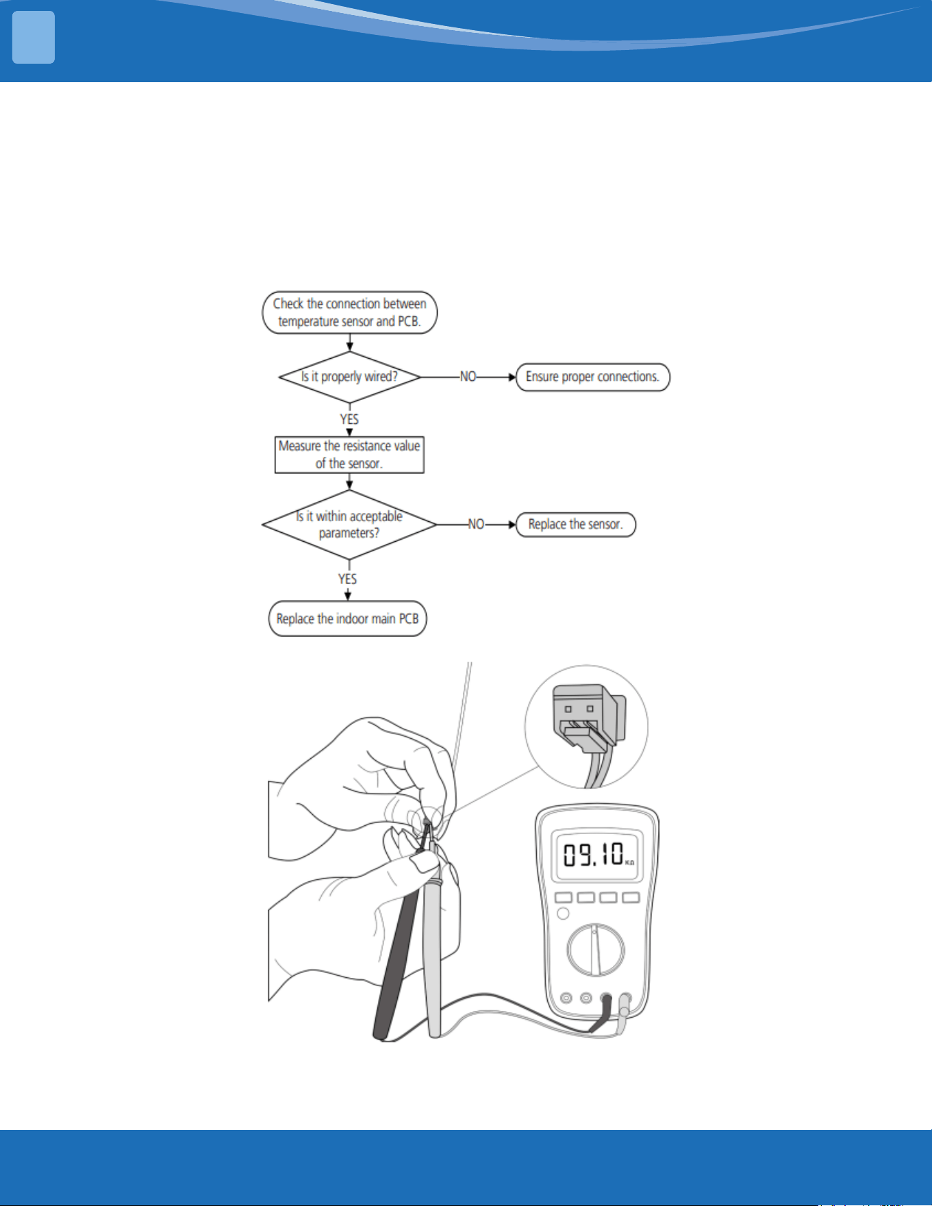
mrcool.com63
TROUBLESHOOTING
TS05-IDU: Open circuit or short circuit of indoor temperature sensor (T1, T2)
diagnosis and solution
Description: If the sampling voltage is lower than 0.06V or higher than 4.94V, the LED displays the
failure code.
Recommended parts to prepare:
• Connection wires
• Sensors
• Indoor main PCB
Troubleshooting and repair:
Note: The picture and the value are for reference only, actual appearance and values may vary.
4
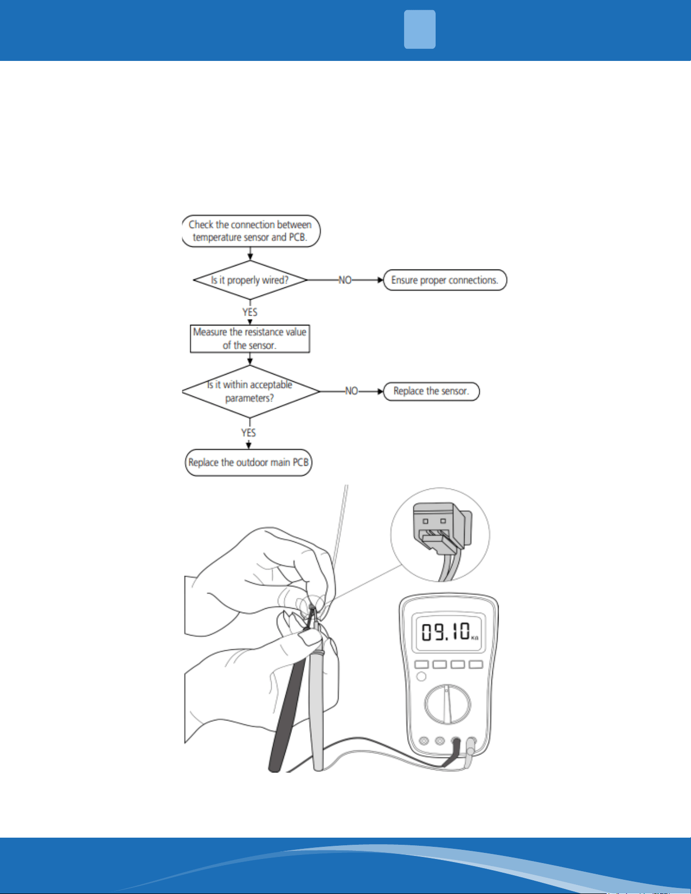
mrcool.com 64
TS05-ODU: Open circuit or short circuit of outdoor temperature sensor (T3, T4, TP,
T2B, TH) diagnosis and solution
Description: If the sampling voltage is lower than 0.06V or higher than 4.94V the LED displays the
failure code.
Recommended parts to prepare:
• Connection wires
• Sensors
• Outdoor main PCB
Troubleshooting and repair:
Note: For certain models the outdoor unit will use a combination sensor, T3, T4 and TP are the same
sensor. This picture and value are for reference only, actual appearance and value may vary.
4
TROUBLESHOOTING
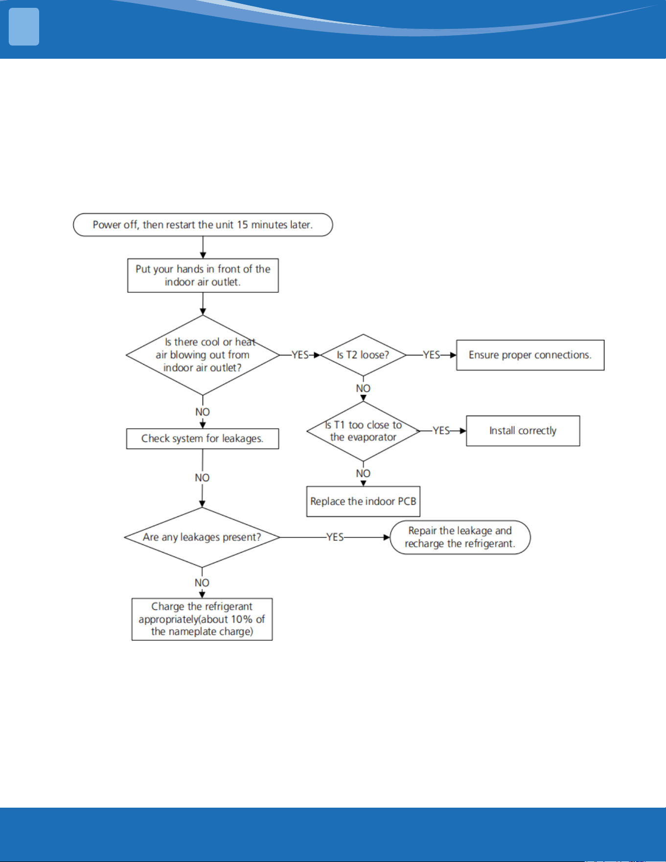
mrcool.com65
TROUBLESHOOTING
TS06-INV: System lacks refrigerant diagnosis and solution
Description: Judging the abnormality of the refrigeration system according to the number of
compressor as well as the changes in the operating parameters caused by excessive exhaust
temperature.
Recommended parts to prepare:
• Indoor PCB
• Additional refrigerant
Troubleshooting and repair:
4
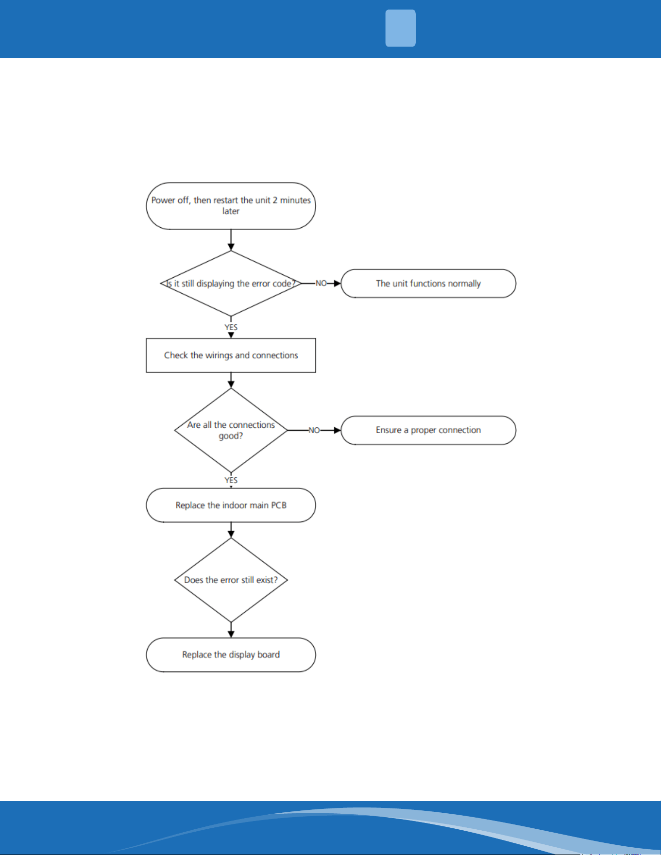
mrcool.com 66
TS07: Indoor PCB/Display board communication error diagnosis and solution
Description: Indoor PCB does not receive feedback from the display board.
Recommended parts to prepare:
• Communication wire
• Indoor PCB
• Display board
Troubleshooting and repair:
4
TROUBLESHOOTING
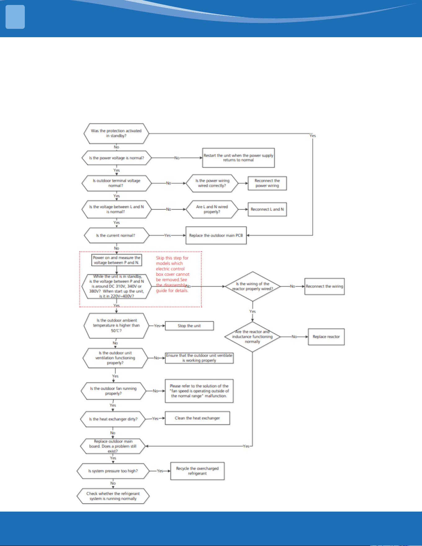
mrcool.com67
TROUBLESHOOTING
TS08-S: Current overload protection diagnosis and solution
Description: An abnormal current rise is detected by checking the specied current detection circuit.
Recommended parts to prepare:
• Connection wires
• Reactor
• Outdoor fan
• Outdoor PCB
Troubleshooting and repair:
4
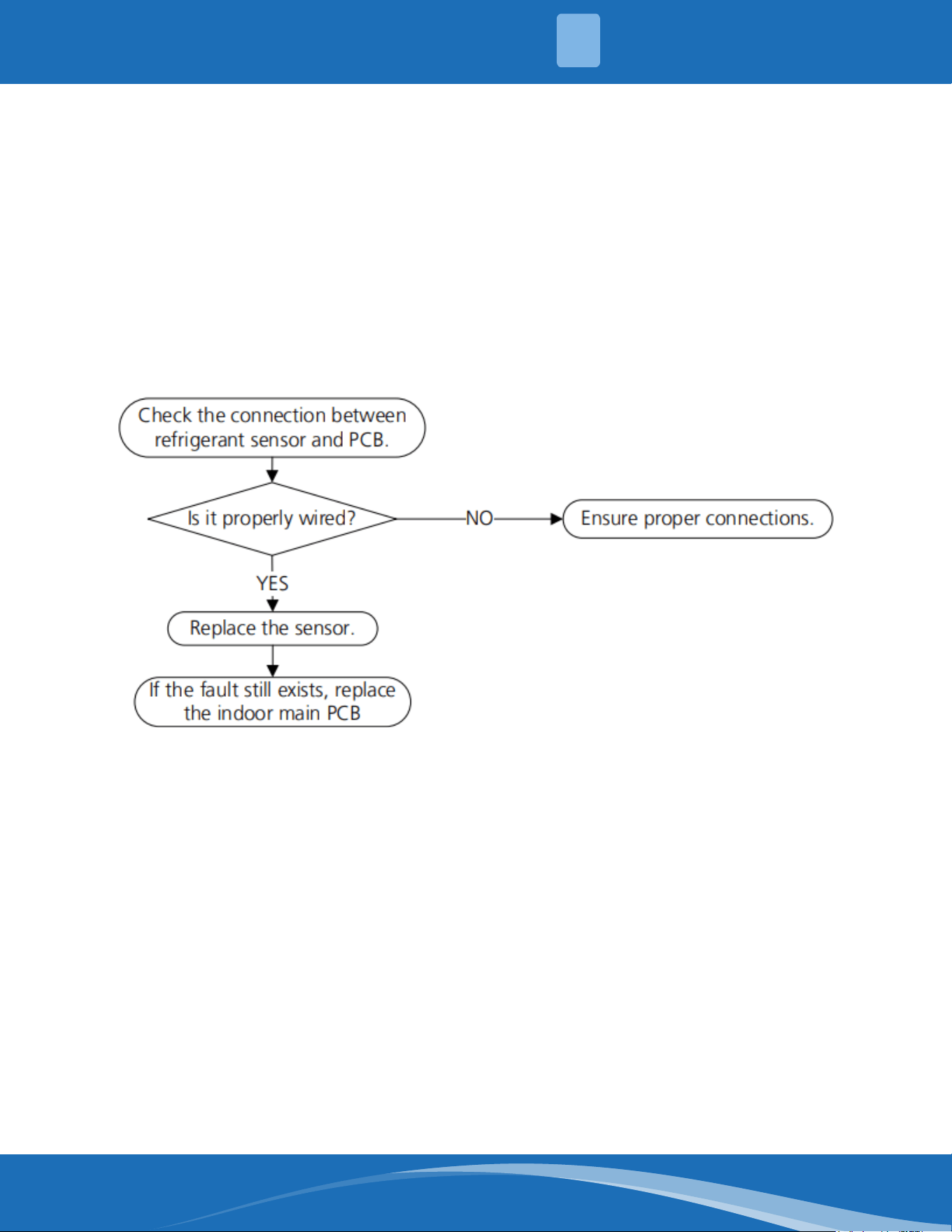
mrcool.com 68
TS05-N10: Refrigerant sensor error or refrigerant sensor is out of range diagnosis
and solution
Description: The indoor unit receives a fault signal for 10s or the indoor unit does not receive
feedback from the refrigerant sensor for 150s.
Recommended parts to prepare:
• Connection wires
• Sensors
• Indoor main PCB
Troubleshooting and repair:
4
TROUBLESHOOTING
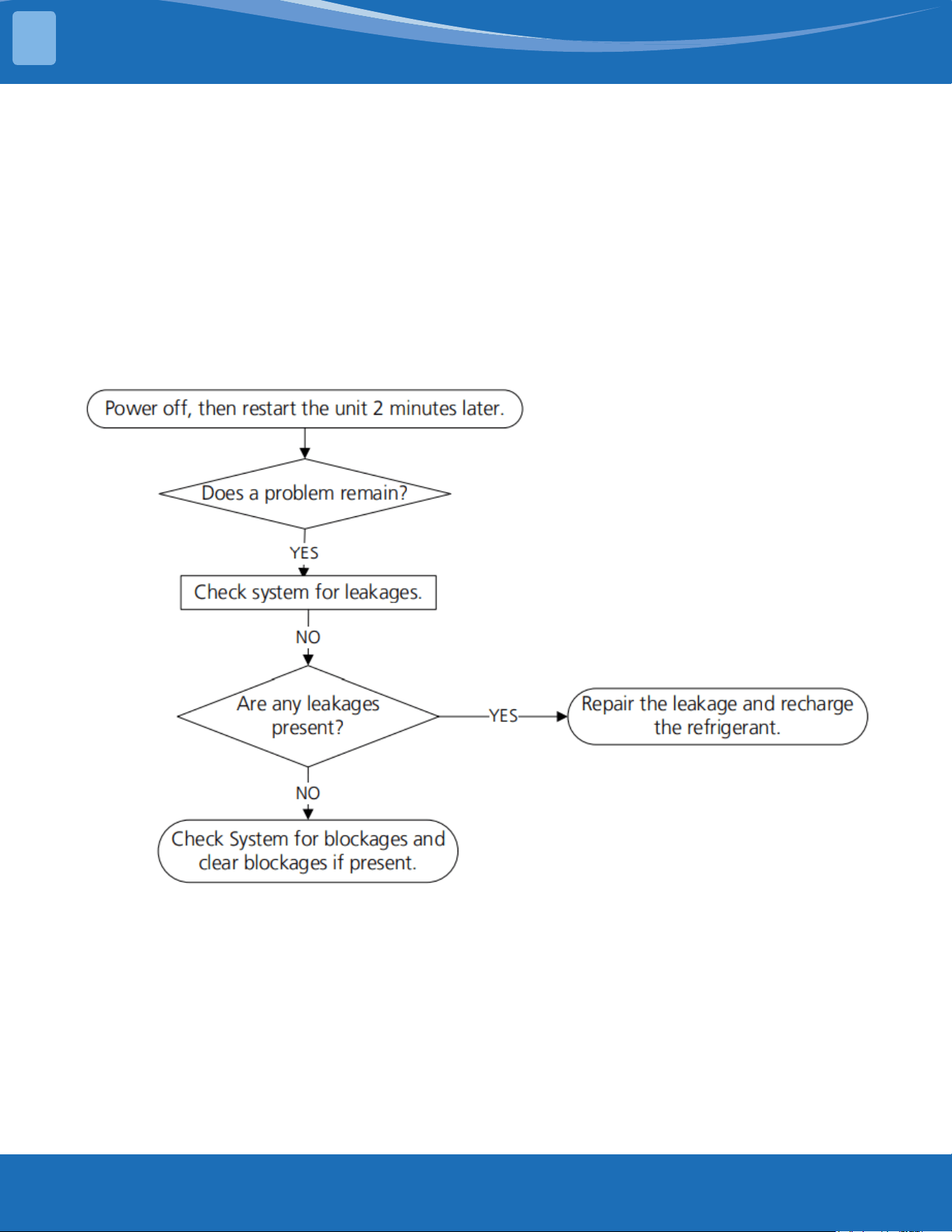
mrcool.com69
TROUBLESHOOTING
TS06-N10: Refrigerant sensor detects leakage or refrigerant sensor is out of range
and leakage is detected diagnosis and solution
Description: The refrigerant sensor detects a concentration higher than or equal to 10%*LFL for 10
seconds or the refrigerant sensor detects a concentration higher than or equal to 20%*LFL or the multi
model receives the refrigerant leakage protection fault sent by the outdoor unit.
Multi-zone: Only the buzzer of the indoor unit that detects refrigerant leakage continues to sound the
alarm, the shortest sound is 10 seconds and the longest sound is 5 minutes (you can press any key
on the remote control, wired controller, APP, and so on to eliminate the alarm) and any other non-
refrigerant leakage fault the indoor unit will only display ECC1 and the buzzer will not make a sound.
Recommended parts to prepare:
• Additional refrigerant
Troubleshooting and repair:
4
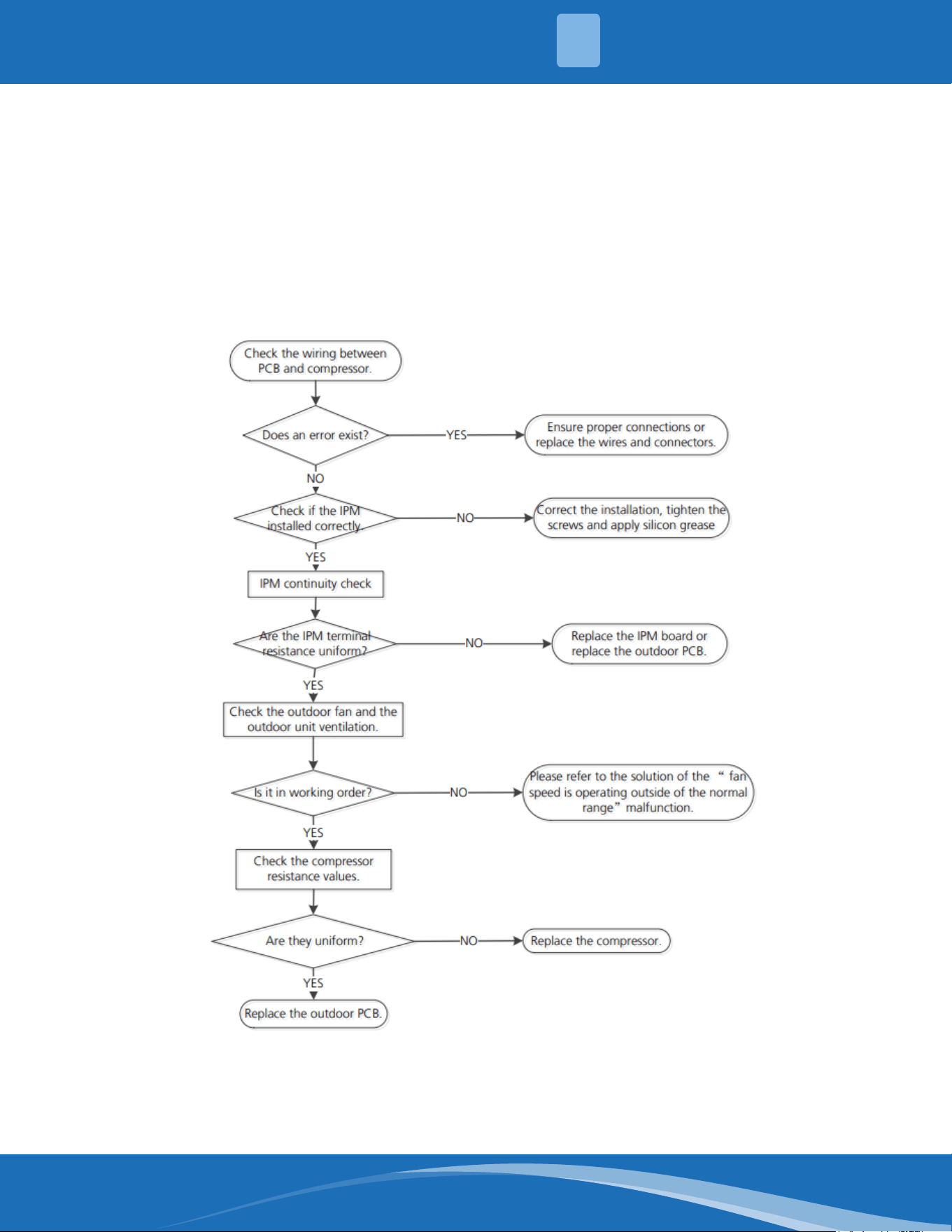
mrcool.com 70
TS09-S: ODU IPM module protection diagnosis and solution
Description: When the voltage signal the IPM sends to the compressor drive chip is abnormal the LED
displays a fault code and the system turns o.
Recommended parts to prepare:
• Connection wires
• IPM module board
• Outdoor fan assembly
• Compressor
• Outdoor PCB
Troubleshooting and repair:
4
TROUBLESHOOTING
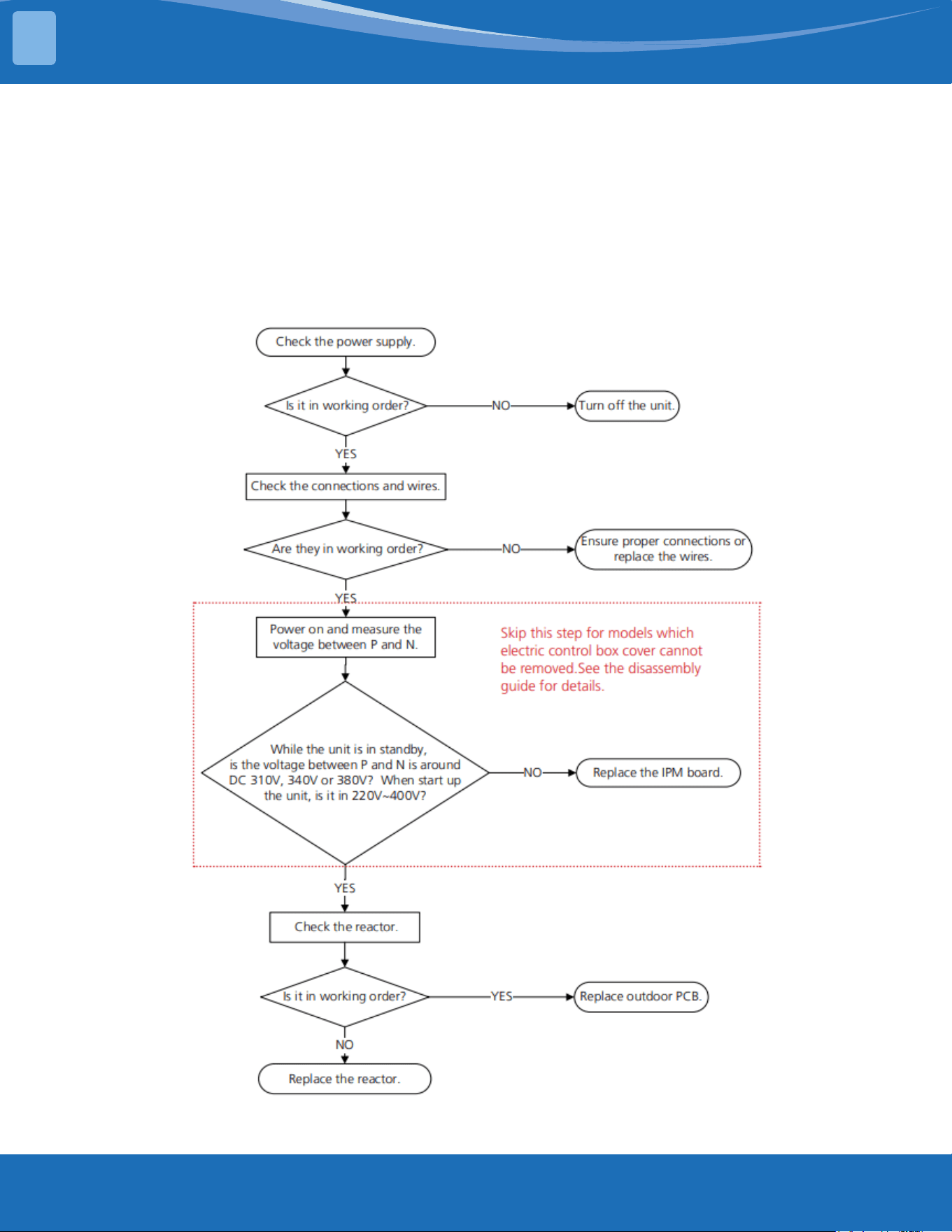
mrcool.com71
TROUBLESHOOTING
TS10-S: ODU voltage protection diagnosis and solution
Description: Abnormal increases or decreases in voltage are detected by checking the specied
voltage detection circuit.
Recommended parts to prepare:
• Power supply wires
• IPM module board
• PCM
• Reactor
Troubleshooting and repair:
4
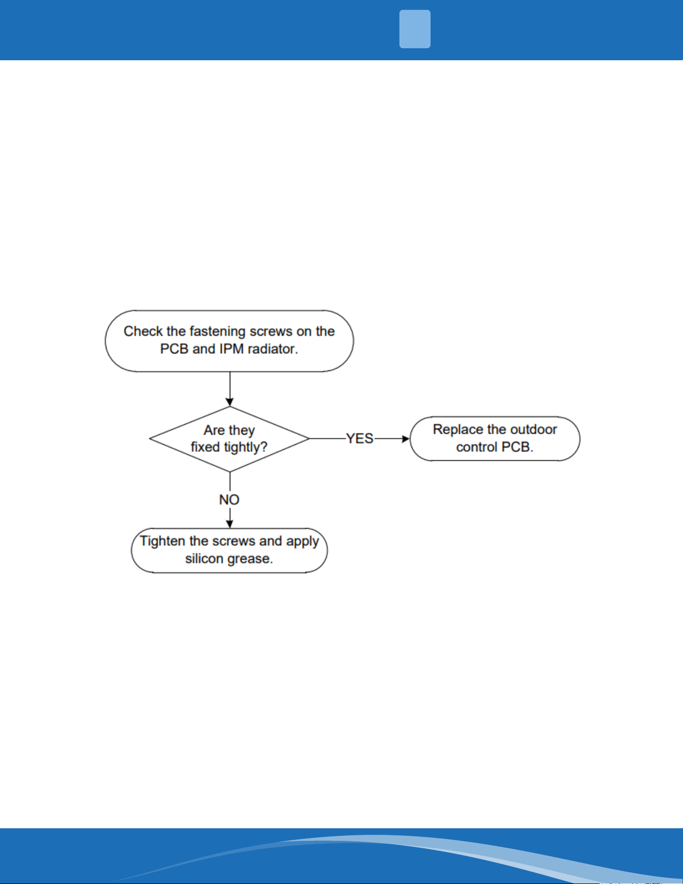
mrcool.com 72
TS11-S-INV: Compressor top (or IPM) temp. Protection diagnosis and solution
Description: If the temperature of the IPM module is higher than a certain value the LED displays a
fault code.
Recommended parts to prepare:
• Connection wires
• Outdoor PCB
• IPM module board
• High pressure protector
• System blockages
Troubleshooting and repair:
4
TROUBLESHOOTING
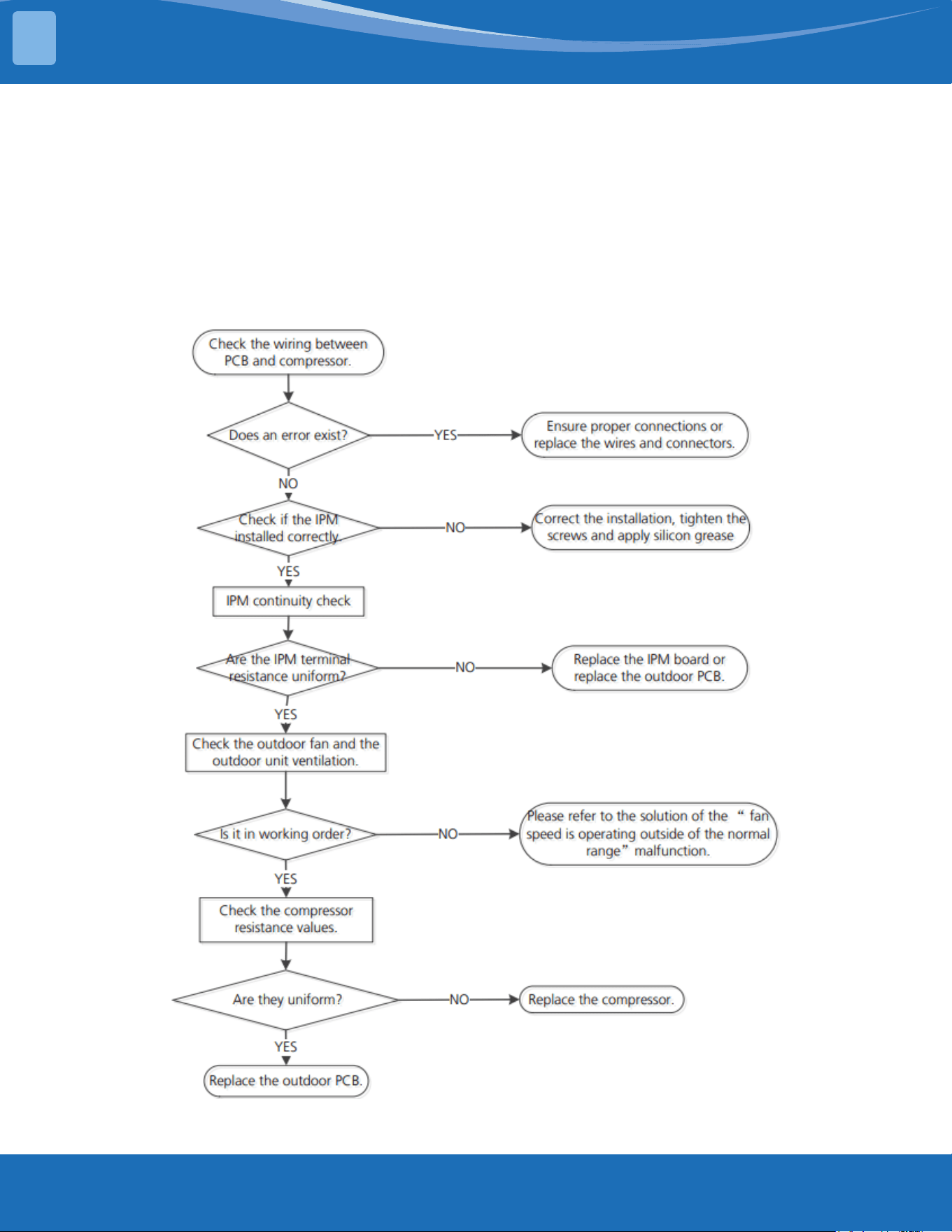
mrcool.com73
TROUBLESHOOTING
TS12-S: Inverter compressor drive error diagnosis and solution
Description: An abnormal inverter compressor drive is detected by a special detection circuit including
communication signal detection, voltage detection, compressor rotation speed signal detection, ect.
Recommended parts to prepare:
• Connection wires
• Outdoor PCB
• IPM module board
• Outdoor fan assembly
• Compressor
Troubleshooting and repair:
4
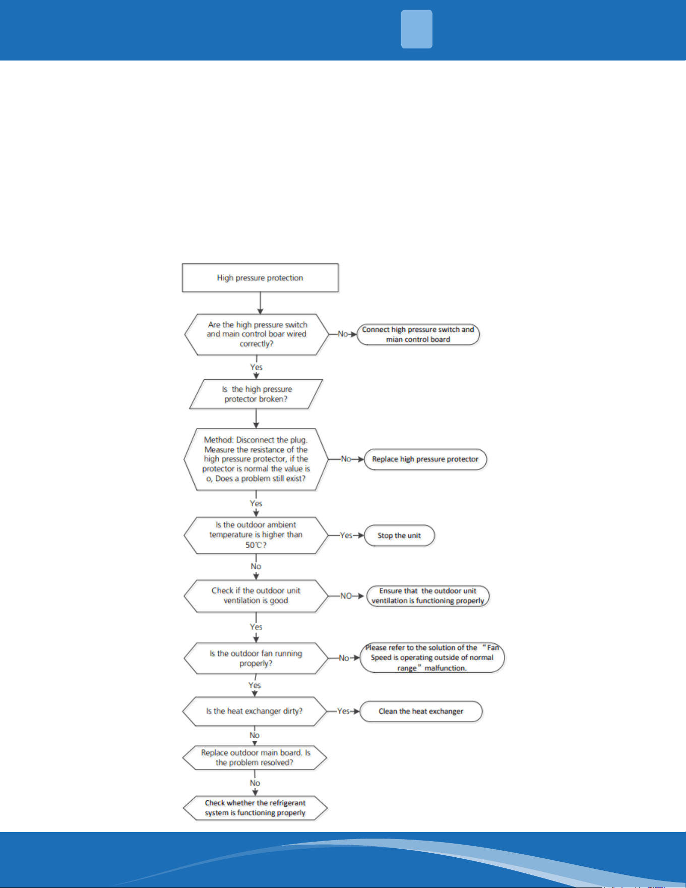
mrcool.com 74
TS26-INV: System pressure protection (low or high pressure) diagnosis and
solution
Description: The outdoor pressure switch cut o the system due to high pressure (if pressure is higher
than 638 PSI (4.4MPa)). Or the outdoor pressure switch cut o the system due to low pressure (if the
pressure is lower than 18.85 PSI (0.13MPa) the LED will display a fault code.
Recommended parts to prepare:
• Connection wires
• Outdoor PCB
• Refrigerant
• Pressure switch
• Outdoor fan
Troubleshooting and repair:
4
TROUBLESHOOTING
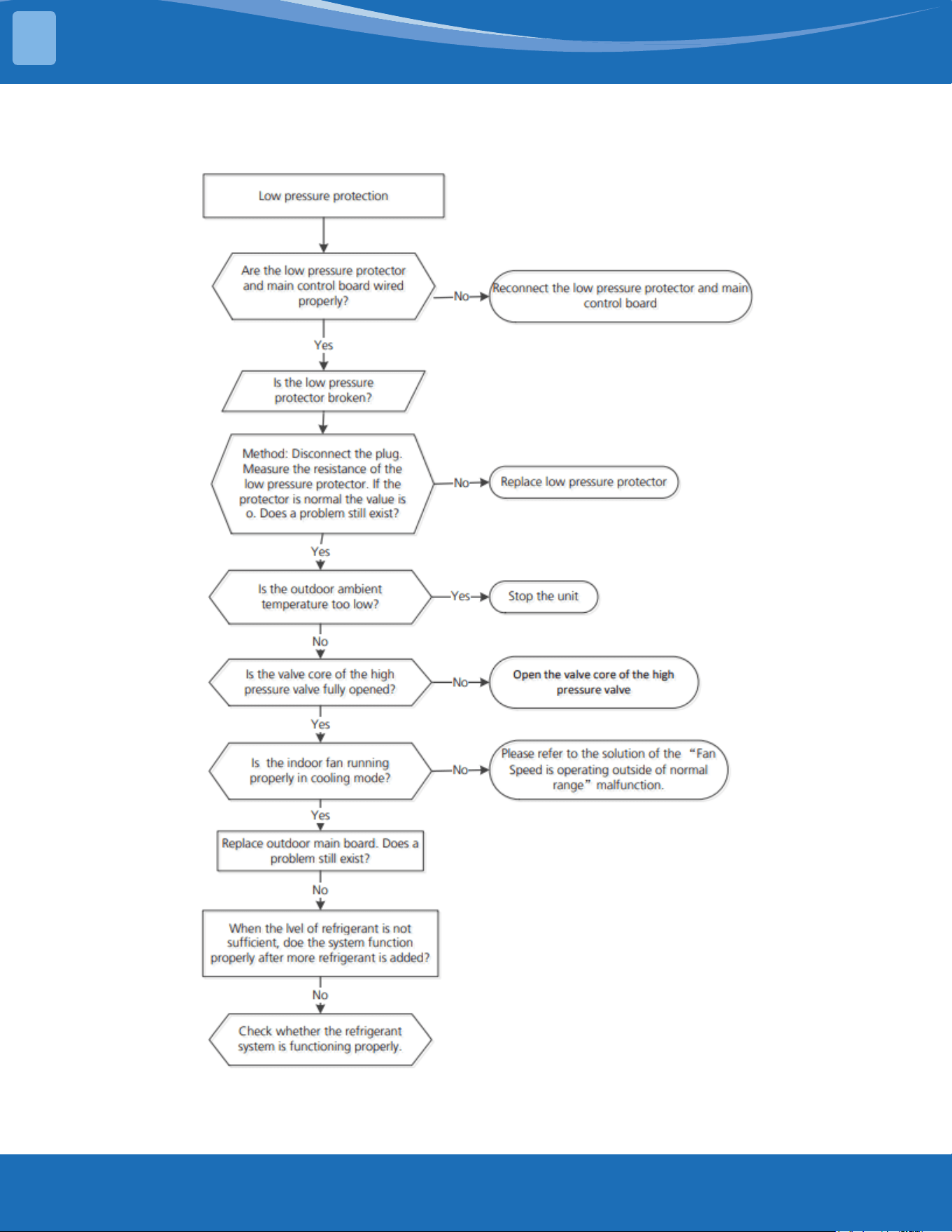
mrcool.com75
TROUBLESHOOTING
TS26-INV Cont.
4
mrcool.com 76
TS14: IDUs mode conict (match with multi outdoor unit)
Description: The indoor units cannot work in cooling mode and heating mode at the same time.
Heating mode always has priority.
• Suppose indoor unit A is working in cooling mode or fan mode, and indoor unit B is set to heating
mode, unit A will change to o and unit B will continue working in heating mode.
• Suppose indoor unit A is working in heating mode and indoor unit B is set to cooling or fan mode,
unit B will then change to standby and unit A will have no change.
Note:
No: No mode conict
Yes: Mode conict
LP (Low temperature protection of outdoor unit)
Description: LP is a protection function. When the compressor is o the outdoor ambient temperature
(T4) is lower than -31°F (-35°C) for 10s, the system will stop and display the fault code.
When the compressor is on and the outdoor ambient temperature (T4) is lower than -40°F (-40°C) for
10s the system will stop and display the fault code.
When the outdoor ambient temperature (T4) is no lower than -25.6°F (-32°C) for 10s, the unit will exit
protection.
Cooling
mode
Heating
mode
Fan O
Cooling
mode
No Yes No No
Heating
mode
Yes No Yes No
Fan No Yes No No
O No No No No
4
TROUBLESHOOTING
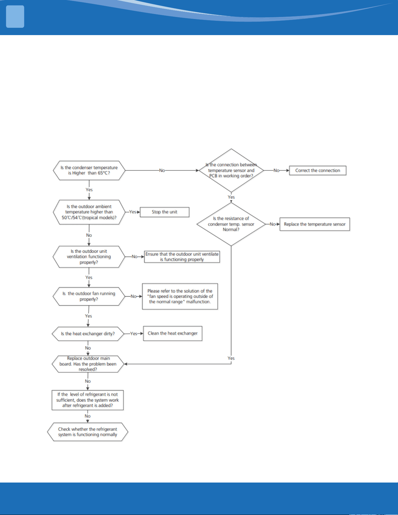
mrcool.com77
TROUBLESHOOTING
TS27-INV: High temperature protection of condenser diagnosis and solution
Description: When the outdoor pipe temperature sensor is no more than 149°F (65°C) the unit will
stop. It will start again only when the outdoor pipe temperature sensor is less than 125.6°F (52°C).
Recommended parts to prepare:
• Connection wires
• Outdoor main PCB
• Condenser temperature sensor
• Refrigerant
• Outdoor fan
Troubleshooting and repair:
4
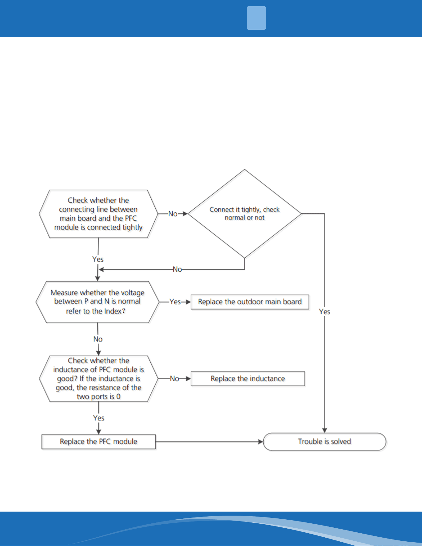
mrcool.com 78
TS30: PFC module protection diagnosis and solution
Description: When the voltage signal that the IPM sends to the compressor drive chip is abnormal the
LED will display the fault code and the system will turn o.
Recommended parts to prepare:
• Connection wires
• Outdoor main PCB
• Inductance
• PFC module
Troubleshooting and repair:
First test the resistance between every two ports of U,V,W of the IPM and P,N. If any result in reading
0 or close to 0 the IPM is defective, otherwise please follow the procedure below:
4
TROUBLESHOOTING
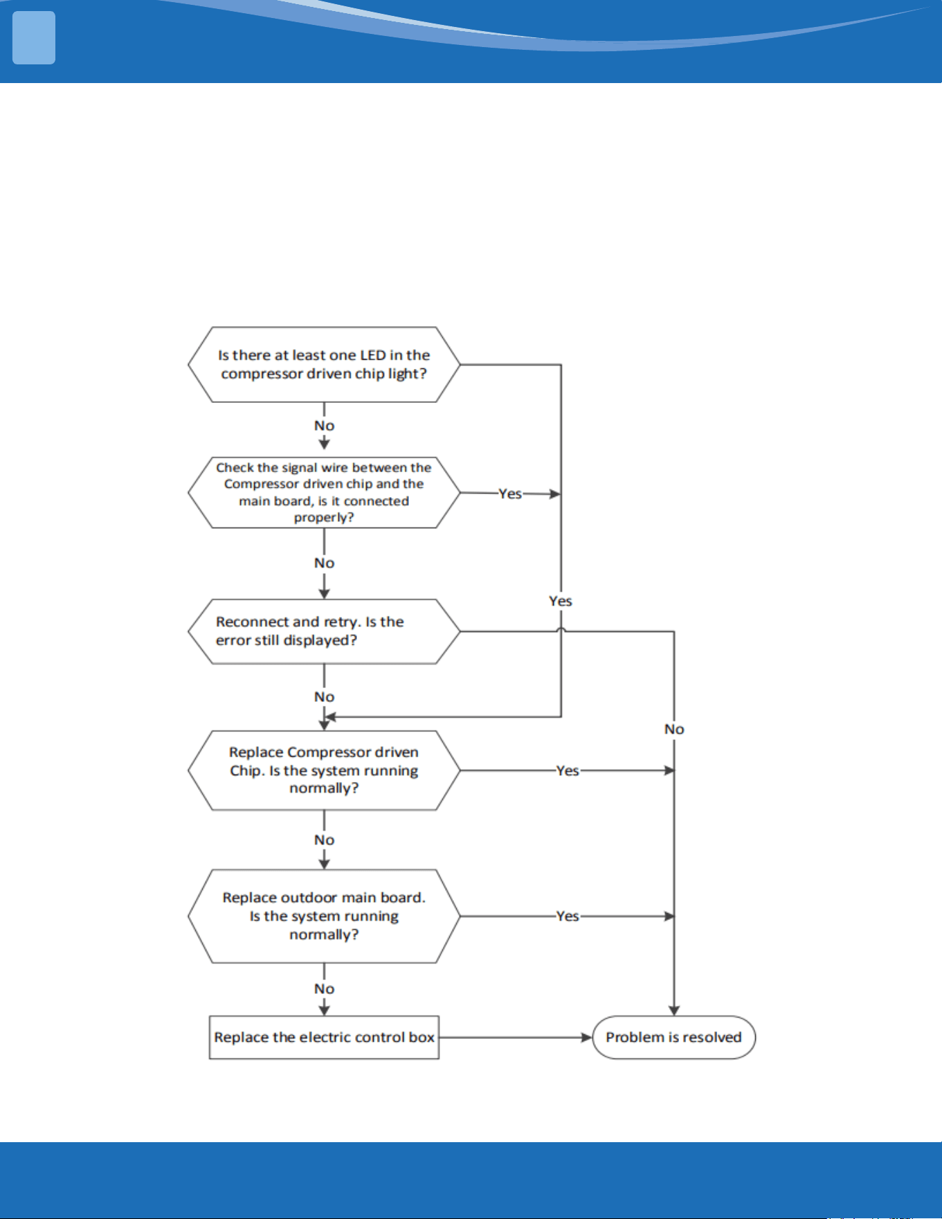
mrcool.com79
TROUBLESHOOTING
TS31: Communication error between the outdoor main chip and the compressor
drive chip diagnosis and solution
Description: The main PCB cannot detect the IPM board.
Recommended parts to prepare:
• Connection wires
• Outdoor main PCB
• IPM board
• Electric control box
Troubleshooting and repair:
4
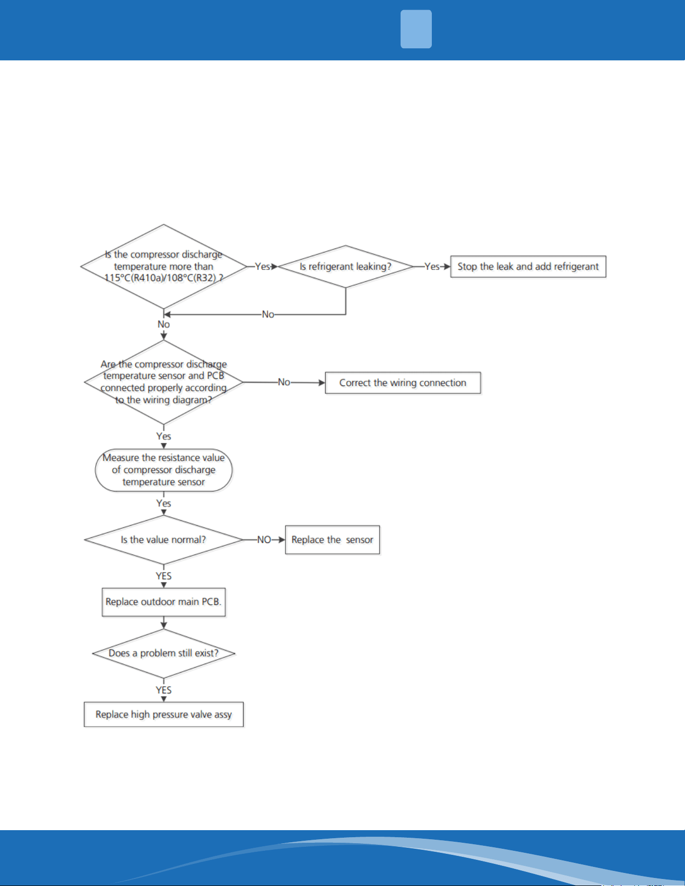
mrcool.com 80
TS32: Discharge temperature protection of compressor diagnosis and solution
Description: If the compressor discharge temperature exceeds a certain level for 9s the compressor
will cease operation and the LED will display a fault code.
Recommended parts to prepare:
• Connection wires
• Outdoor main PCB
• Discharge temperature sensor
• Additional refrigerant
Troubleshooting and repair:
Note: For certain models the outdoor unit will use a combination sensor, T3, T4 and TP are the same
sensor. This picture and value are for reference only, actual appearance and value may vary.
4
TROUBLESHOOTING
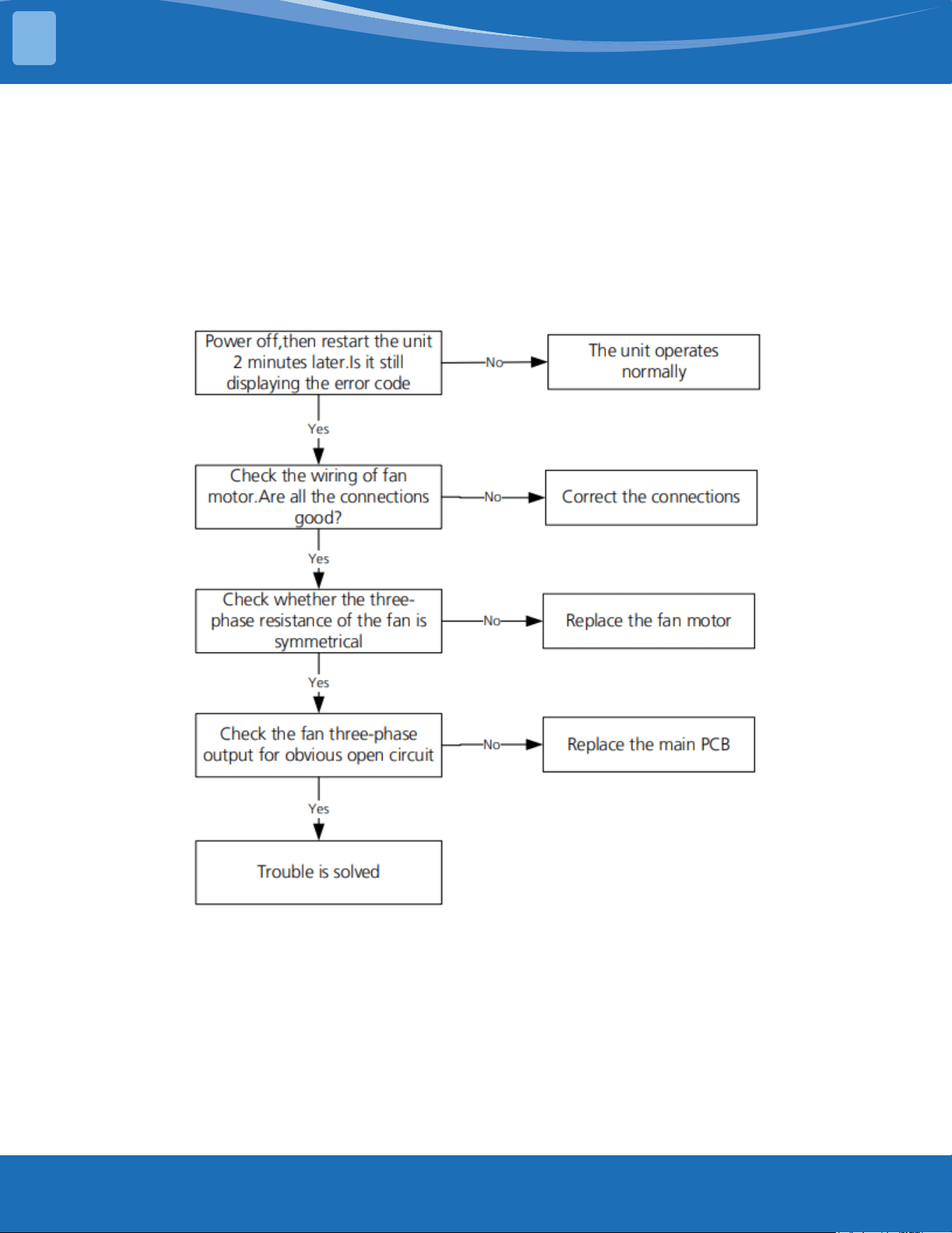
mrcool.com81
TROUBLESHOOTING
TS38: Lack of phase failure of ODU DC fan motor diagnosis and solution
Description: When the three-phase sampling current of the DC motor is abnormal (especially when
the current of one or more phases is always small and almost 0) the LED display will show a fault code.
Recommended parts to prepare:
• Connection wires
• Outdoor main PCB
• Fan motor
Troubleshooting and repair:
4
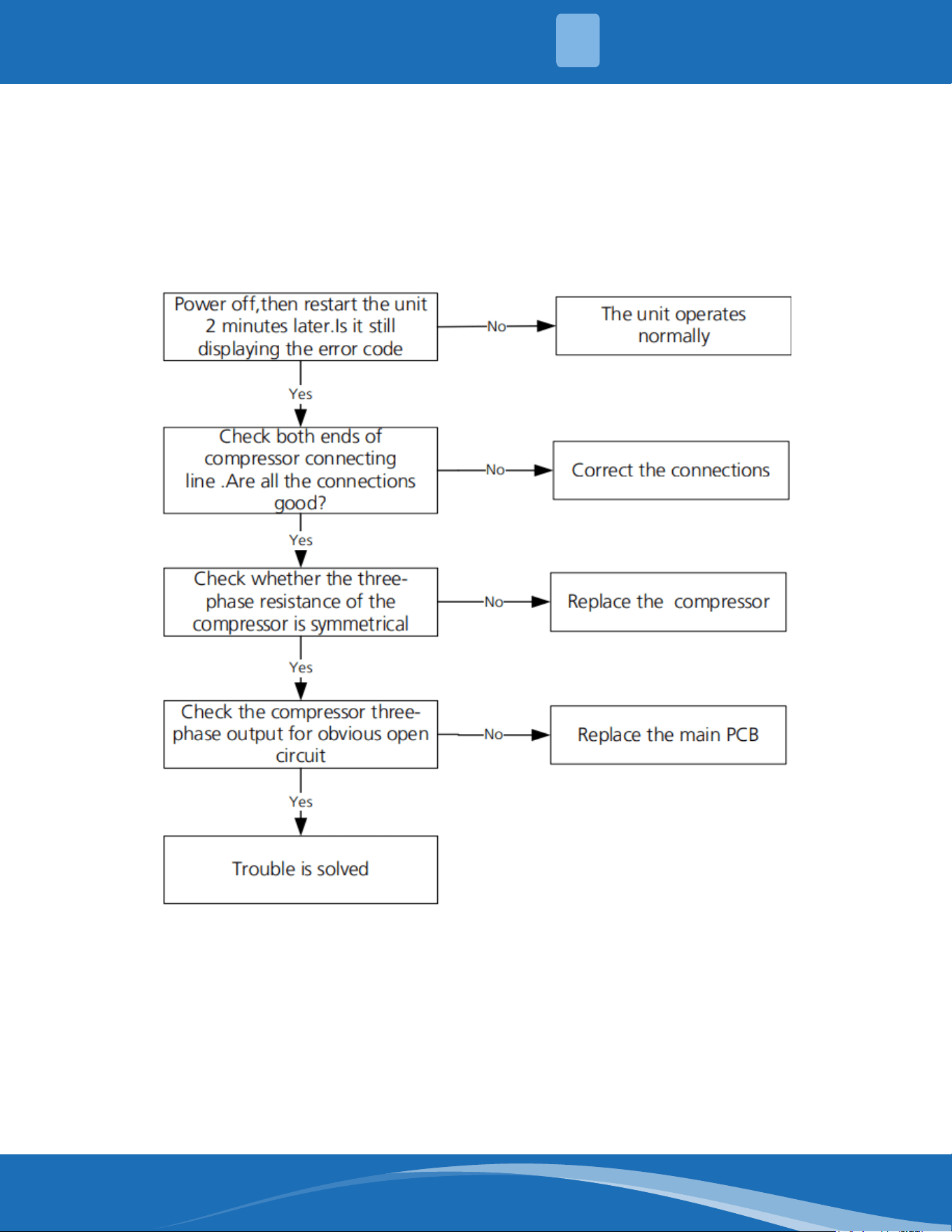
mrcool.com 82
TS39: ODU compressor lack of phase protection diagnosis and solution
Description: When the three-phase sampling current of the DC motor is abnormal (especially when
the current of one or more phases is always small and almost 0) the LED display will show a fault code.
Recommended parts to prepare:
• Connection wires
• Outdoor main PCB
• Compressor
Troubleshooting and repair:
4
TROUBLESHOOTING
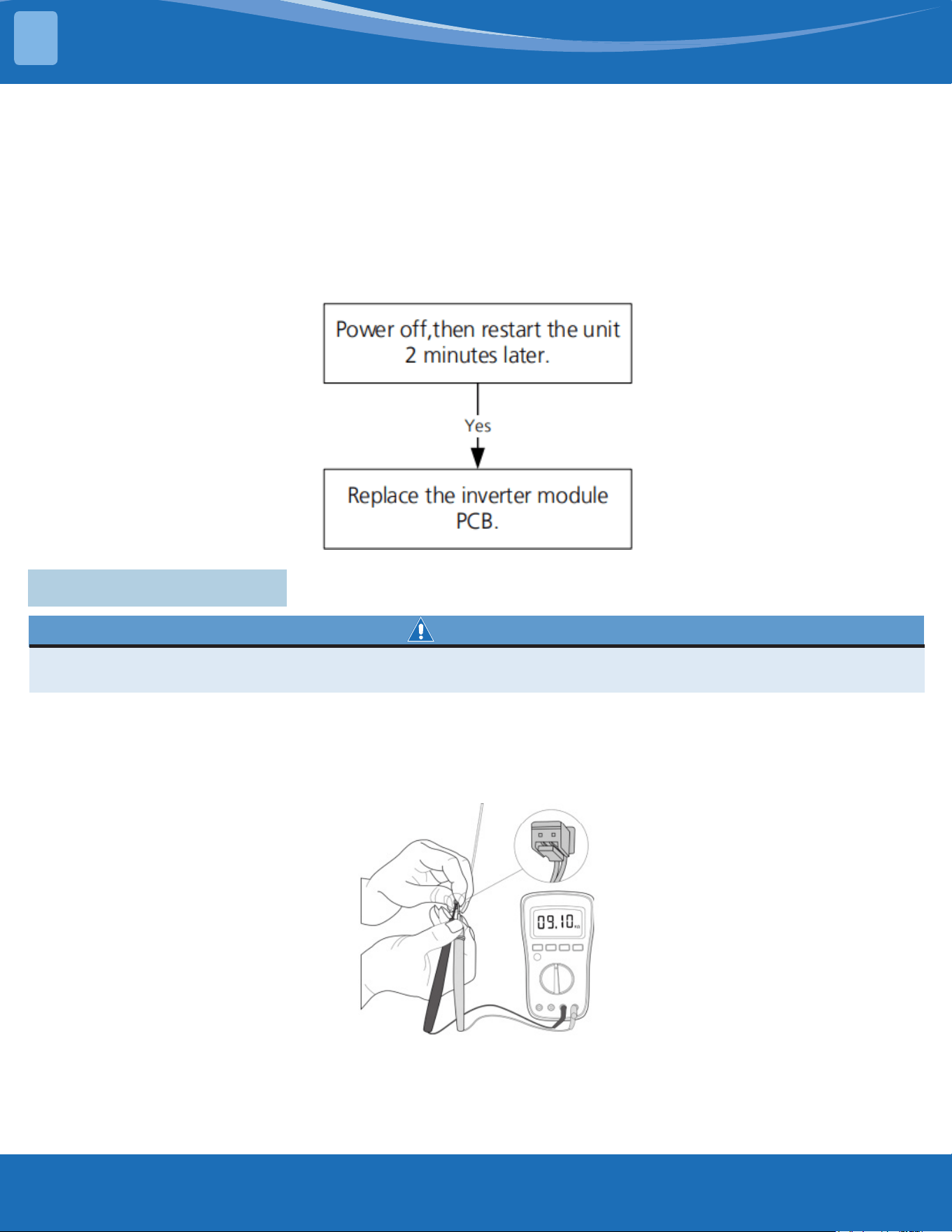
mrcool.com83
TROUBLESHOOTING
TS40: ODU IR chip drive failure diagnosis and solution
Description: When the IR chip detects its own parameter error the LED displays the fault code when
powered on.
Recommended parts to prepare:
• Inverter module PCB
Troubleshooting and repair:
4.8 Check Procedures
WARNING
Be sure to turn o all power supplies or disconnect all wires to avoid electric shock. Operate only after
the compressor and coil has returned to normal temperature in case of injury.
1. Disconnect the temperature sensor from the PCB.
2. Measure the resistance value of the sensor using a multi-meter.
3. Check corresponding temperature sensor resistance value table.
Note: The picture and the value are for reference only, actual condition and specic values may vary.
4
Temperature Sensor Check:
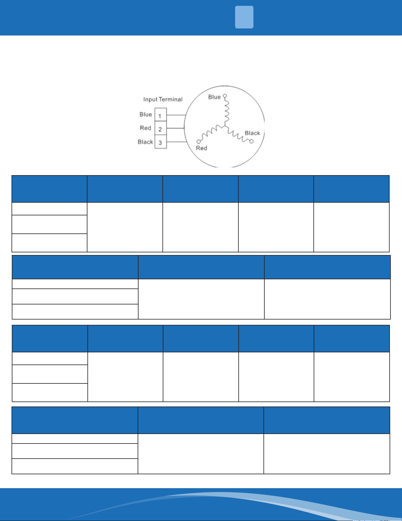
mrcool.com 84
Compressor Check:
1. Disconnect the compressor power cord from the outdoor PCB.
2. Measure the resistance value of each winding using a multi-meter.
3. Check the resistance value of each winding in the following table.
Resistance Value KSK89D53UEZ KSK89D29UEZD KSN98D22UFZ
KSK103D33UEZ3
KSK103D33UEZ3(MD)
KSK103D33UEZ3
Blue-Red
2.35±5%Ω
(at 68°F (20°C))
1.99±5%Ω
(at 68°F (20°C))
1.57±5%Ω
(at 68°F (20°C))
2.13±5%Ω
(at 68°F (20°C))
Blue-Black
Red-Black
Resistance Value KSK103D32UEZ31
KTN150D30UFZA
KTN150D30SFZA
Blue-Red
4.06±5%Ω
(at 68°F (20°C))
1.02±5%Ω
(at 68°F (20°C)
Blue-Black
Red-Black
Resistance Value KSM135D23UFZ KTN110D42UFZ KSN140D21UFZ KTM140D78UFZ3
Blue-Red
1.75±5%Ω
(at 68°F (20°C))
1.82±5%Ω
(at 68°F (20°C))
1.28±5%Ω
(at 68°F (20°C))
1.5±5%Ω
(at 68°F (20°C))
Blue-Black
Red-Black
Resistance Value
KTF235D22UMT
ATF235D22TMT
KTF250D22UMT
KTM240D46UKT2
Blue-Red
0.75±5%Ω
(at 68°F (20°C))
1.04±5%Ω
(at 68°F (20°C)
Blue-Black
Red-Black
4
TROUBLESHOOTING
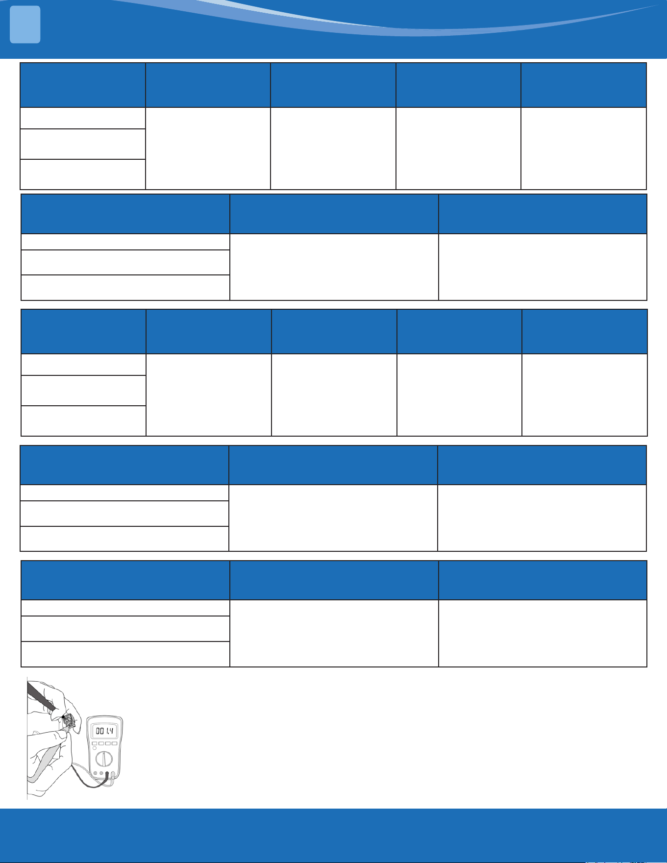
mrcool.com85
TROUBLESHOOTING
Resistance Value KSN140D58UFZ KTM240D43UKT KSN98D64UFZ23 ASN140D35TFZ
Blue-Red
1.86±5%Ω
(at 68°F (20°C))
1.03±5%Ω
(at 68°F (20°C))
2.7±5%Ω
(at 68°F (20°C))
0.83±5%Ω
(at 68°F (20°C))
Blue-Black
Red-Black
Resistance Value KTF420D62UNT ASN108D22TEZ
Blue-Red
0.86±5%Ω
(at 68°F (20°C))
1.76±5%Ω
(at 68°F (20°C)
Blue-Black
Red-Black
Resistance Value KTM240D63SKT2 KTM240D57UMT DTN210D32UFZ KSN140D33UFZB3
Blue-Red
1.19±5%Ω
(at 68°F (20°C))
0.62±5%Ω
(at 68°F (20°C))
1.7±5%Ω
(at 68°F (20°C))
1.68±5%Ω
(at 68°F (20°C))
Blue-Black
Red-Black
Resistance Value KTM110D79UFZA3 GSD098XKUF7JV6B
Blue-Red
1.88±5%Ω
(at 68°F (20°C))
2.83±5%Ω
(at 68°F (20°C)
Blue-Black
Red-Black
Resistance Value KSK75D33UEZD3 DTN210D54UEZ3
Blue-Red
2.14±5%Ω
(at 68°F (20°C))
2.53±5%Ω
(at 68°F (20°C)
Blue-Black
Red-Black
Note: The picture and the value are for reference only, actual condition and
specic values may vary.
4
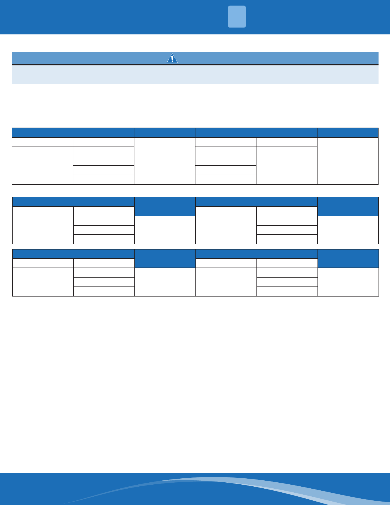
mrcool.com 86
WARNING
Electricity remains in capacitors even when the power supply is o. Ensure the capacitors are fully
discharged before troubleshooting.
IPM Continuity Check:
1. Turn o the outdoor unit and disconnect the power supply.
2. Discharge electronic capacitors and ensure all energy-storage units have been discharged.
3. Disassemble the outdoor PCB or disassemble the IPM board.
4. Measure the resistance value between P and U (U,W,N), U(V,W) and N.
Digital tester Resistance Value Digital Tester Resistance Value
(+)Red (-)Black
∞
(Several M±5%Ω)
(+)Red (-)Black
∞
(Several M±5%Ω)
P
N U
N
U V
V W
W -
Or test the conductivity of IPM with diode mode:
Needle-type Tester
Normal Value
Needle-Type Tester
Normal Value
Red Black Red Black
P
U
Open-Circuit N
U
0.3-0.5VV V
W W
Needle-type Tester
Normal Value
Needle-Type Tester
Normal Value
Red Black Red Black
P
U
0.3-0.5V N
U
Open-CircuitV V
W W
4
TROUBLESHOOTING
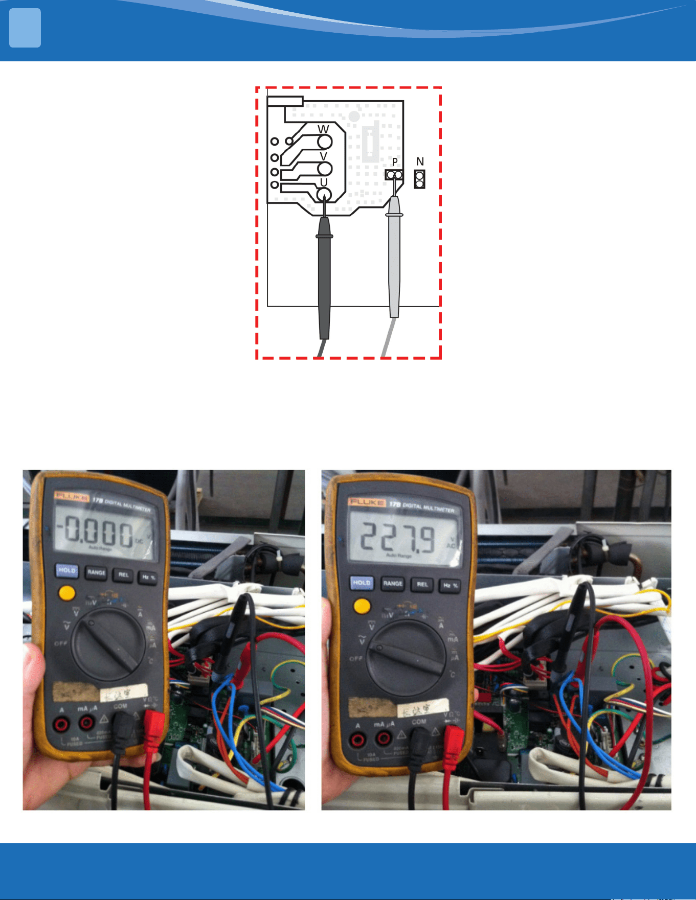
mrcool.com87
TROUBLESHOOTING
Note: The picture and the value are for reference only, actual condition and specic values may vary.
4-way Valve Check
1. Power on and use a digital tester to measure the voltage. When the unit operates in cooling it is 0V,
when the unit operates in heating it is about 230VAC.
If the value of the voltage is not in range the PCB has problems and needs to be replaced.
4
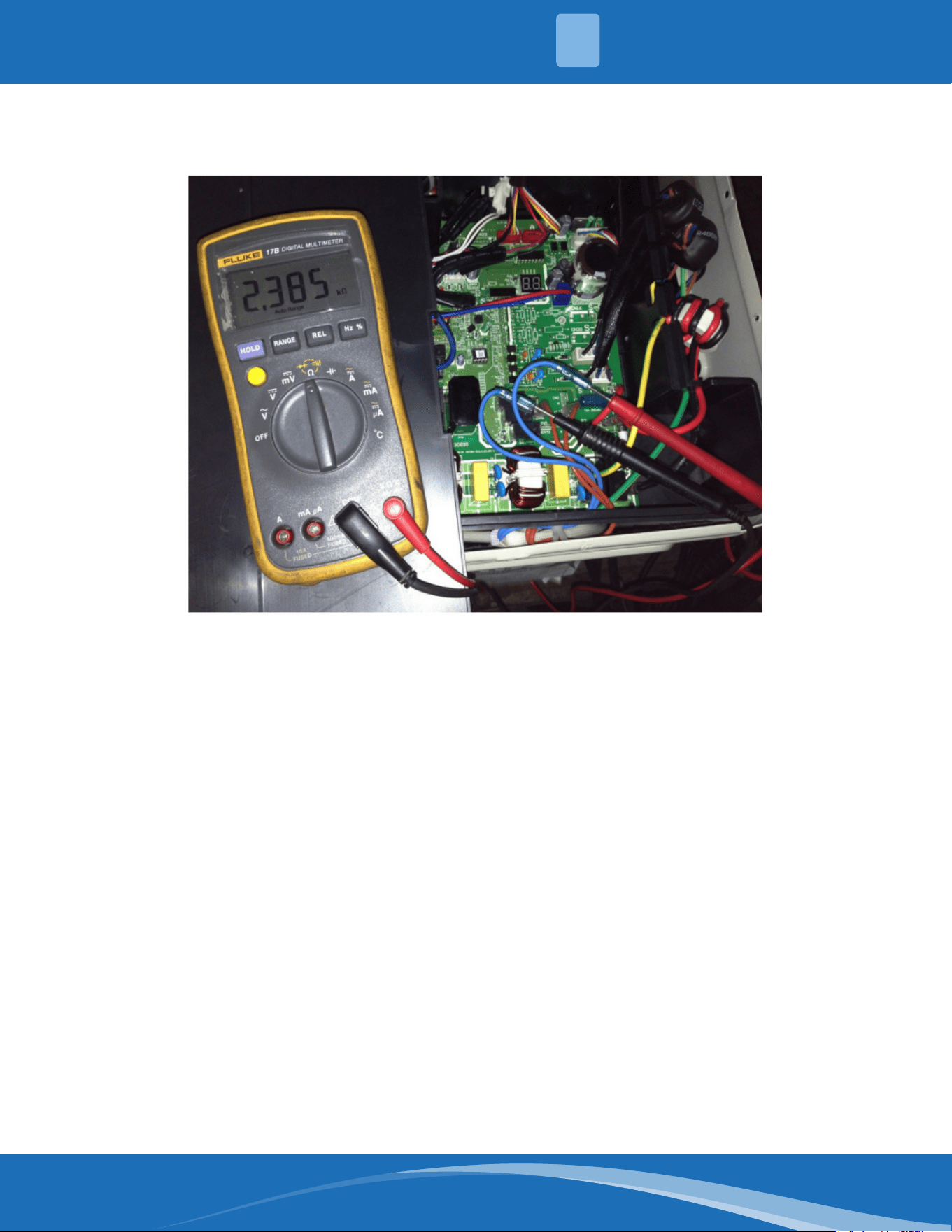
mrcool.com 88
2. Turn the power o and use a digital tester to measure the resistance. The value should be 1.8~2.5
K±5%Ω.
4
TROUBLESHOOTING
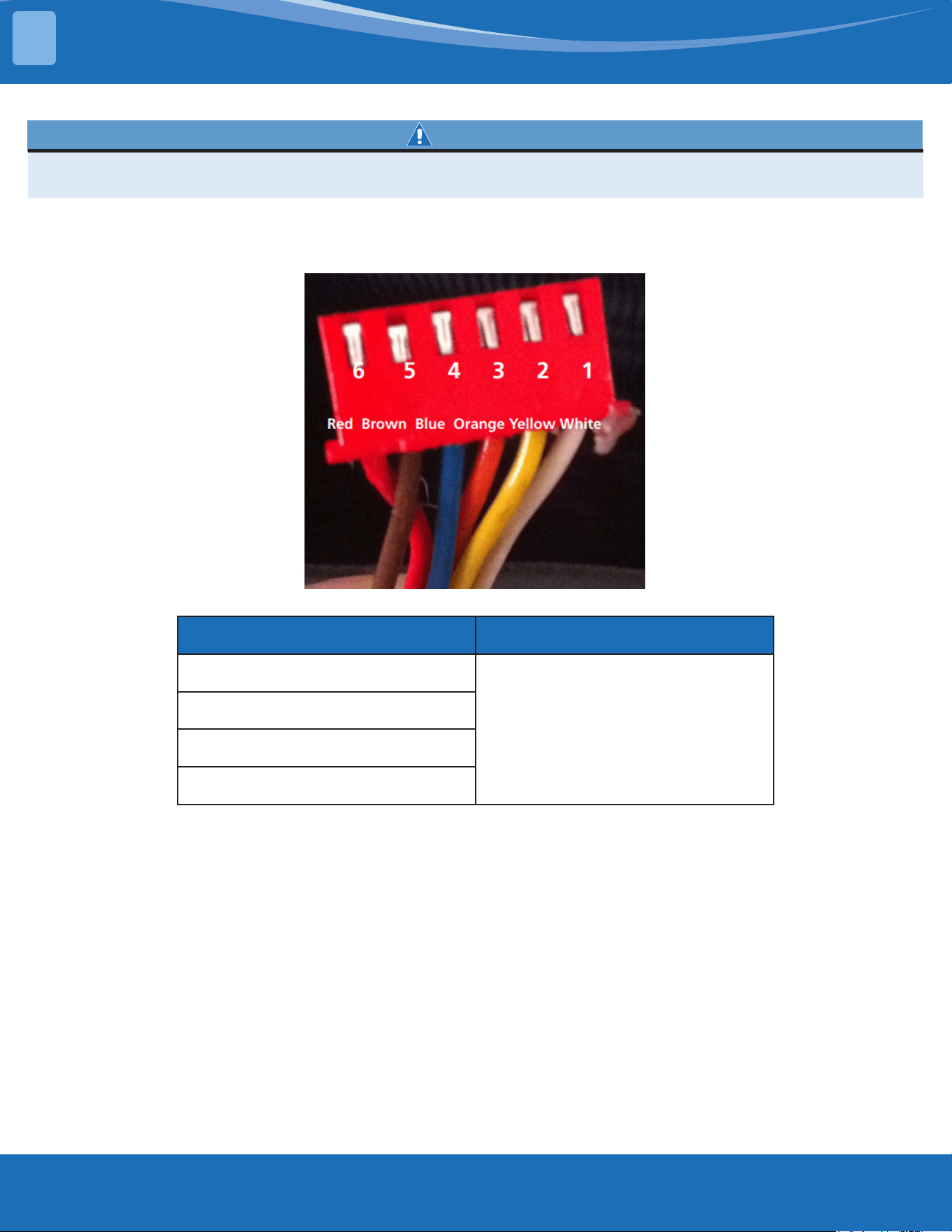
mrcool.com89
TROUBLESHOOTING
EXV (EEV) Check:
WARNING
Electricity remains in capacitors even when the power supply is o. Ensure the capacitors are fully
discharged before troubleshooting.
1. Disconnect the connector from the outdoor PCB.
2. Measure the resistance value of each winding using a multi-meter.
3. Check the resistance value of each winding in the following table.
Color of Lead Winding Normal Value
Red-Blue
About 50Ω
Red-Yellow
Brown-Orange
Brown-White
4
mrcool.com 90
°C °F K Ohm °C °F K Ohm °C °F K Ohm °C °F K Ohm
-20 -4 542.7 20 68 68.66 60 140 13.59 100 212 3.702
-19 -2 511.9 21 70 65.62 61 142 13.11 101 214 3.595
-18 0 483 22 72 62.73 62 144 12.65 102 216 3.492
-17 1 455.9 23 73 59.98 63 145 12.21 103 217 3.392
-16 3 430.5 24 75 57.37 64 147 11.79 104 219 3.296
-15 5 406.7 25 77 54.89 65 149 11.38 105 221 3.203
-14 7 384.3 26 79 52.53 66 151 10.99 106 223 3.113
-13 9 363.3 27 81 50.28 67 153 10.61 107 225 3.025
-12 10 343.6 28 82 48.14 68 154 10.25 108 226 2.941
-11 12 325.1 29 84 46.11 69 156 9.902 109 228 2.86
-10 14 307.7 30 86 44.17 70 158 9.569 110 230 2.781
-9 16 291.3 31 88 42.33 71 160 9.248 111 232 2.704
-8 18 275.9 32 90 40.57 72 162 8.94 112 234 2.63
-7 19 261.4 33 91 38.89 73 163 8.643 113 235 2.559
-6 21 247.8 34 93 37.3 74 165 8.358 114 237 2.489
-5 23 234.9 35 95 35.78 75 167 8.084 115 239 2.422
-4 25 222.8 36 97 34.32 76 169 7.82 116 241 2.357
-3 27 211.4 37 99 32.94 77 171 7.566 117 243 2.294
-2 28 200.7 38 100 31.62 78 172 7.321 118 244 2.233
-1 30 190.5 39 102 30.36 79 174 7.086 119 246 2.174
0 32 180.9 40 104 29.15 80 176 6.859 120 248 2.117
1 34 171.9 41 106 28 81 178 6.641 121 250 2.061
2 36 163.3 42 108 26.9 82 180 6.43 122 252 2.007
3 37 155.2 43 109 25.86 83 181 6.228 123 253 1.955
4 39 147.6 44 111 24.85 84 183 6.033 124 255 1.905
5 41 140.4 45 113 23.89 85 185 5.844 125 257 1.856
6 43 133.5 46 115 22.89 86 187 5.663 126 259 1.808
7 45 127.1 47 117 22.1 87 189 5.488 127 261 1.762
8 46 121 48 118 21.26 88 190 5.32 128 262 1.171
9 48 115.2 49 120 20.46 89 192 5.157 129 264 1.674
10 50 109.8 50 122 19.69 90 194 5 130 266 1.632
11 52 104.6 51 124 18.96 91 196 4.849
12 54 99.69 52 126 18.26 92 198 4.703
13 55 95.05 53 127 17.58 93 199 4.562
14 57 90.66 54 129 16.94 94 201 4.426
15 59 86.49 55 131 16.32 95 203 4.294
16 61 82.54 56 133 15.73 96 205 4.167
17 63 78.79 57 135 15.16 97 207 4.045
18 64 75.24 58 136 14.62 98 208 3.927
19 66 71.86 59 138 14.09 99 210 3.812
5.1 Temperature Sensor Resistance Value Table for TP (°C-K)
5
TEMPERATURE SENSOR RESISTANCE TABLE
mrcool.com91
TEMPERATURE SENSOR RESISTANCE TABLE
Other Temperature Sensor Resistance Value Table (°C-K)
°C °F K Ohm °C °F K Ohm °C °F K Ohm °C °F K Ohm
-20 -4 115.266 20 68 12.6431 60 140 2.35774 100 212 0.62973
-19 -2 108.146 21 70 12.0561 61 142 2.27249 101 214 0.61148
-18 0 101.517 22 72 11.5 62 144 2.19073 102 216 0.59386
-17 1 96.3423 23 73 10.9731 63 145 2.11241 103 217 0.57683
-16 3 89.5865 24 75 10.4736 64 147 2.03732 104 219 0.56038
-15 5 84.219 25 77 10 65 149 1.96532 105 221 0.54448
-14 7 79.311 26 79 9.55074 66 151 1.89627 106 223 0.52912
-13 9 74.536 27 81 9.12445 67 153 1.89627 107 225 0.51426
-12 10 70.1698 28 82 8.71983 68 154 1.83003 108 226 0.49989
-11 12 66.0898 29 84 8.3356 69 156 1.76647 109 228 0.486
-10 14 62.2756 30 86 7.97078 70 158 1.70547 110 230 0.47256
-9 16 58.7079 31 88 7.62411 71 160 1.64691 111 232 0.45957
-8 18 56.3694 32 90 7.29464 72 162 1.59068 112 234 0.44699
-7 19 52.2438 33 91 6.98142 73 163 1.53668 113 235 0.43482
-6 21 49.3161 34 93 6.68355 74 165 1.48481 114 237 0.42304
-5 23 46.5725 35 95 6.40021 75 167 1.43498 115 239 0.41164
-4 25 44 36 97 6.13059 76 169 1.38703 116 241 0.4006
-3 27 41.5878 37 99 5.87359 77 171 1.34105 117 243 0.38991
-2 28 39.8239 38 100 5.62961 78 172 1.29078 118 244 0.37956
-1 30 37.1988 39 102 5.3689 79 174 1.25423 119 246 0.36954
0 32 35.2024 40 104 5.17519 80 176 1.2133 120 248 0.35982
1 34 33.3269 41 106 4.96392 81 178 1.17393 121 250 0.35042
2 36 31.5635 42 108 4.76253 82 180 1.13604 122 252 0.3413
3 37 29.9058 43 109 4.5705 83 181 1.09958 123 253 0.33246
4 39 28.3459 44 111 4.38736 84 183 1.06448 124 255 0.3239
5 41 26.8778 45 113 4.21263 85 185 1.03069 125 257 0.31559
6 43 25.4954 46 115 4.04589 86 187 0.99815 126 259 0.30754
7 45 24.1932 47 117 3.88673 87 189 0.96681 127 261 0.29974
8 46 22.5662 48 118 3.73476 88 190 0.93662 128 262 0.29216
9 48 21.8094 49 120 3.58962 89 192 0.90753 129 264 0.28482
10 50 20.7184 50 122 3.45097 90 194 0.8795 130 266 0.2777
11 52 19.6891 51 124 3.31847 91 196 0.85248 131 268 0.27078
12 54 18.7177 52 126 3.19183 92 198 0.82643 132 270 0.26408
13 55 17.8005 53 127 3.07075 93 199 0.80132 133 271 0.25757
14 57 16.9341 54 129 2.95896 94 201 0.77709 134 273 0.25125
15 59 16.1156 55 131 2.84421 95 203 0.7537 135 275 0.24512
16 61 15.3418 56 133 2.73823 96 205 0.73119 136 277 0.23916
17 63 14.6181 57 135 2.63682 97 207 0.68844 137 279 0.23338
18 64 13.918 58 136 2.53973 98 208 0.66818 138 280 0.22776
19 66 13.2631 59 138 2.4467 99 210 0.64862 139 282 0.22231
5
mrcool.com 92
Pressure Temperature Pressure Temperature
Kpa Bar PSI °C °F Kpa Bar PSI °C °F
58.196 0.58 8.44 -60 -76 935.23 9.35 135.64 8 46.4
61.517 0.62 8.92 -59 -74.2 963.75 9.64 139.78 9 48.2
64.988 0.65 9.43 -58 -72.4 992.93 9.93 14401 10 50
68.615 0.69 9.95 -57 -70.6 1022.8 10.23 148.34 11 51.8
72.402 .072 10.50 -56 -68.8 1053.3 10.53 152.76 12 53.6
76.354 0.76 11.07 -55 -67 1084.5 10.85 157.29 13 55.4
80.478 0.80 11.67 -54 -65.2 1116.4 11.16 161.91 14 57.2
84.776 0.85 12.30 -53 -63.4 1149 11.49 166.64 15 59
89.256 0.89 12.95 -52 -61.6 1182.3 11.82 171.47 16 60.8
93.923 0.94 13.62 -51 -59.8 1216.3 12.16 176.40 17 62.6
98.781 0.99 14.33 -50 -58 1251.1 12.51 181.45 18 64.4
103.84 1.04 15.06 -49 -56.2 1286.6 12.87 186.60 19 66.2
109.1 1.09 15.82 -48 -54.4 1322.8 13.23 191.85 20 68
114.56 1.15 16.61 -47 -52.6 1359.9 13.60 197.23 21 69.8
120.25 1.20 17.44 -46 -50.8 1397.7 13.98 202.71 22 71.6
126.15 1.26 18.30 -45 -49 1436.3 14.36 208.31 23 73.4
132.28 1.32 19.18 -44 -47.2 1475.7 14.76 214.02 24 75.2
138.64 1.39 20.11 -43 -45.4 1515.9 15.16 219.85 25 77
145.24 1.45 21.06 -42 -43.6 1557 15.57 225.82 26 78.8
152.09 1.52 22.06 -41 -41.8 1598.9 15.99 231.89 27 80.6
159.18 1.59 23.09 -40 -40 1641.6 16.42 238.09 28 82.4
166.54 1.67 24.15 -39 -38.2 1685.2 16.85 244.41 29 84.2
174.15 1.74 25.26 -38 -36.4 1729.7 17.30 250.86 30 86
182.04 1.82 26.40 -37 -34.6 1775 17.75 257.43 31 87.8
190.2 1.90 27.59 -36 -32.8 1821.3 18.21 264.15 32 89.6
198.65 1.99 28.81 -35 -31 1868.4 18.68 270.98 33 91.4
207.39 2.07 30.08 -34 -29.2 1916.5 19.17 277.95 34 93.2
216.42 2.16 31.39 -33 -27.4 1965.6 19.66 285.08 35 95
225.76 2.26 32.74 -32 -25.6 2015.5 20.16 292.31 36 96.8
235.41 2.35 34.14 -31 -23.8 2066.5 20.67 299.71 37 98.6
245.37 2.45 35.59 -30 -22 2118.4 21.18 307.24 38 100.4
255.67 2.56 37.08 -29 -20.2 2171.3 21.71 314.19 39 102.2
266.29 2.66 38.62 -28 -18.4 2225.2 22.25 322.73 40 104
277.25 2.77 40.21 -27 -16.6 2280.2 22.80 330.70 41 105.8
288.56 2.89 41.85 -26 -14.8 2336.1 23.36 38.81 42 107.6
300.22 3.00 43.54 -25 -13 2393.2 23.93 347.09 43 109.4
312.24 3.12 45.28 -24 -11.2 2451.3 24.51 355.52 44 111.2
324.63 3.25 47.08 -23 -9.4 2510.4 25.10 364.09 45 113
337.39 3.37 48.93 -22 -7.6 2570.7 25.71 372.84 46 114.8
350.54 3.51 50.84 -21 -5.8 2632.1 26.32 381.74 47 116.6
364.08 3.64 52.80 -20 -4 2694.7 26.95 390.82 48 118.4
378.02 3.78 54.83 -19 -2.2 2758.33 27.58 400.04 49 120.2
392.37 3.92 56.91 -18 -0.4 2823.2 28.23 409.46 50 122
407.13 4.07 59.05 -17 1.4 2889.3 28.89 419.04 51 123.8
6.1 System Pressure Table-R454B
6
SYSTEM PRESSURE TABLE
mrcool.com93
SYSTEM PRESSURE TABLE
Pressure Temperature Pressure Temperature
Kpa Bar PSI °C °F Kpa Bar PSI °C °F
422.31 4.22 61.25 -16 3.2 2956.5 29.57 428.79 52 125.6
437.92 4.38 63.5 -15 5 3025 30.25 438.72 53 127.4
453.98 4.54 65.84 -14 6.8 3094.7 30.95 448.83 54 129.2
470.47 4.70 68.23 -13 8.6 3165.7 31.66 459.13 55 131
487.43 4.87 70.69 -12 10.4 3238.1 32.38 469.63 56 132.8
504.84 5.05 73.22 -11 12.2 3311.7 33.12 480.30 57 134.6
522.73 5.23 75.81 -10 14 3386.7 33.87 491.18 58 136.4
541.1 5.41 78.48 -9 15.8 3463 34.63 502.25 59 138.2
559.95 5.60 81.21 -8 17.6 3540.7 35.41 513.52 60 140
579.31 5.79 84.02 -7 19.4 3619.9 36.20 525.00 61 141.8
599.16 5.99 86.90 -6 21.2 3700.5 37.01 536.69 62 143.6
619.54 6.20 89.85 -5 23 3782.7 37.83 548.61 63 145.4
640.43 6.40 92.88 -4 24.8 3866.3 38.66 560.74 64 147.2
661.86 6.62 95.99 -3 26.6 3951.5 39.52 573.10 65 149
683.82 6.84 99.18 -2 28.4 4038.3 40.38 585.69 66 450.28
706.34 7.06 102.44 -1 30.2 4126.8 41.27 598.52 67 152.6
729.41 7.29 105.79 0 32 4217 42.17 611.60 68 154.4
753.06 7.53 109.22 1 33.8 4309 43.09 624.95 69 156.2
777.28 7.77 112.73 2 35.6 4402.9 44.03 638.56 70 158
802.08 8.02 116.33 3 37.4 4498.7 44.99 652.46 71 159.8
827.47 8.27 120.01 4 39.2 4596.5 45.97 666.64 72 161.6
853.49 8.53 123.78 5 41 4696.5 46.97 681.15 73 163.4
880.11 8.80 127.64 6 42.8 4798.9 47.99 696.00 74 165.5
907.35 9.07 131.60 7 44.6 4904.1 49.04 711.25 75 167
System Pressure Table-R454B Cont.
6

DIY
®
Series
Single-Zone
Mini-Split System
The design and specications of this product and/or manual are subject to change without prior notice.
Consult with the sales agency or manufacturer for details.