
Please read this manual carefully before installation and keep it for future reference.
Due to updates and constantly improving performance, the information and instructions within this
manual are subject to change without notice. Please visit www.mrcool.com/documentation to
ensure you have the latest version of this manual.
Version Date: 06-07-22
Installation & Owner’s
Manual
4th Generation
DIY
®
Multi-Zone
Contents
Page 1 mrcool.com
Safety Precautions
Warnings .................................................................................................................................. 3
Cautions ................................................................................................................................... 5
Parts Overview
Parts Diagram ......................................................................................................................... 6
Display Window ...................................................................................................................... 8
Accessories ................................................................................................................................... 9
Operating Instructions
Operating Temperature ......................................................................................................... 11
Manual Operation ................................................................................................................... 11
Airflow Directional Control .................................................................................................... 12
How the A/C & Heat Pump Work ........................................................................................... 13
Operation Mode Selection ...................................................................................................... 14
Special Functions .................................................................................................................... 14
Care and Maintenance
DISCLAIMER: You are assuming risk by handling materials containing refrigerants under pressure, that
if not handled properly, can cause bodily injury. If you do not feel comfortable conducting this
installation process,we recommend you retain the services of a qualified HVAC professional.
****Electrical work must be completed by a qualified electrical technician.****
!
1
2
3
16
16
16
17
17
4
Installation Diagram .............................................................................
18
Line Set Length Specifications ............................................................................................... 19
Contents
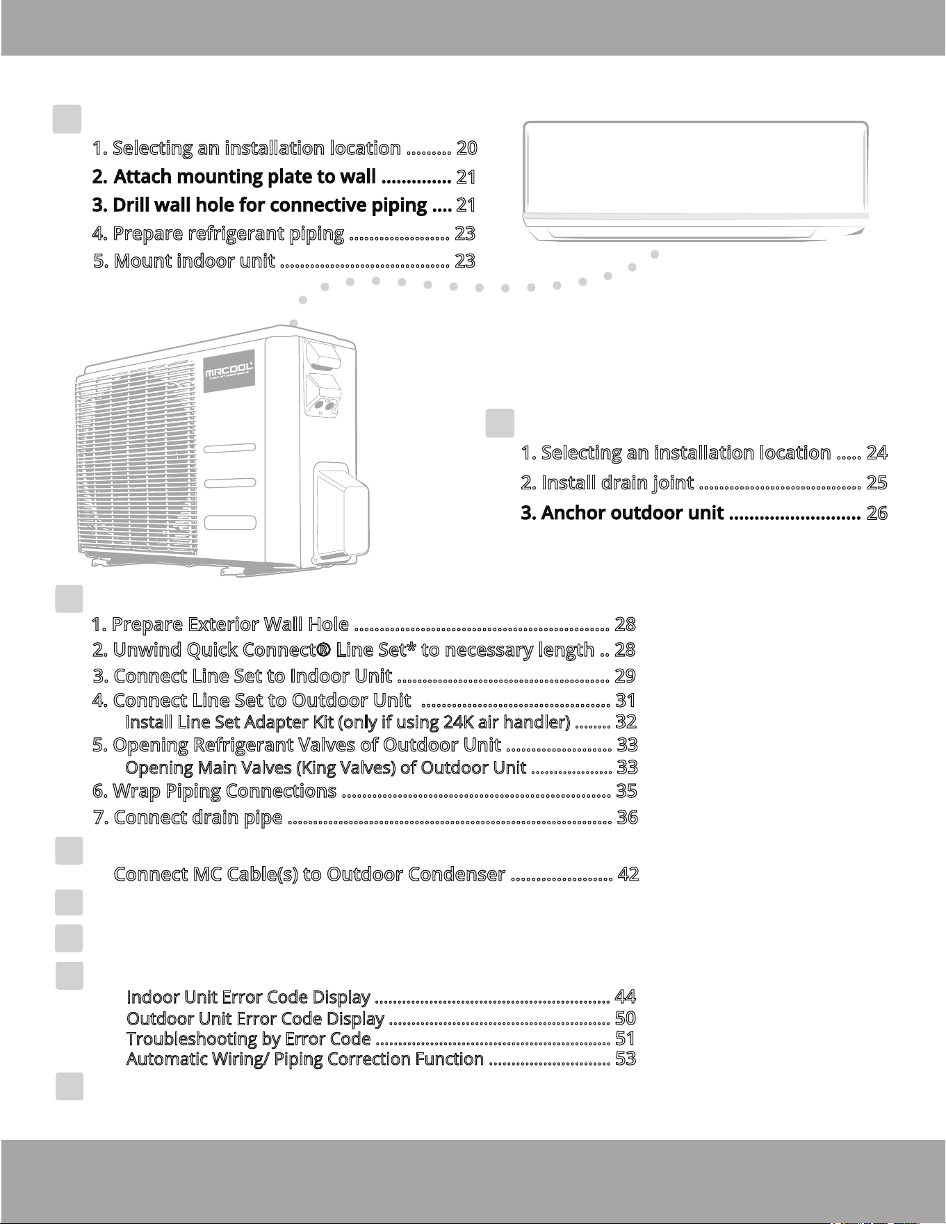
Indoor Unit Installation ........... 20
1. Selecting an installation location ......... 20
4.
Prepare refrigerant piping .................... 23
5. Mount indoor unit .................................. 23
Outdoor Unit Installation ......
24
1. Selecting an installation location ..... 24
2. Install drain joint ................................ 25
6
Refrigerant Piping Connections .................... 28
Electrical Connections .................................... 38
Test Run ............................................................ 45
8
9
10
11
5
Page 2mrcool.com
Electrical and Gas Leak Checks ..................... 44
Troubleshooting .............................................. 47
26
1. Prepare Exterior Wall Hole .................................................. 28
2. Unwind Quick Connect® Line Set* to necessary length .. 28
3. Connect Line Set to Indoor Unit .......................................... 29
4. Connect Line Set to Outdoor Unit ..................................... 31
5. Opening Refrigerant Valves of Outdoor Unit ..................... 33
6. Wrap Piping Connections ..................................................... 35
7. Connect drain pipe ................................................................ 36
21
21
*Pat. https://mrcool.com/mrcool-patents/
Install Line Set Adapter Kit (only if using 24K air handler) ........ 32
Opening Main Valves (King Valves) of Outdoor Unit .................. 33
7
Indoor Unit Error Code Display ....................................................
44
Outdoor Unit Error Code Display .................................................
50
Troubleshooting by Error Code ....................................................
51
Automatic Wiring/ Piping Correction Function ...........................
53
12
EU Disposal Guidelines .................................... 54
Connect MC Cable(s) to Outdoor Condenser .................... 42
Page 3 mrcool.com
Read Before Using
Incorrect usage may cause serious damage or injury.
WARNING
CAUTION
WARNING
!
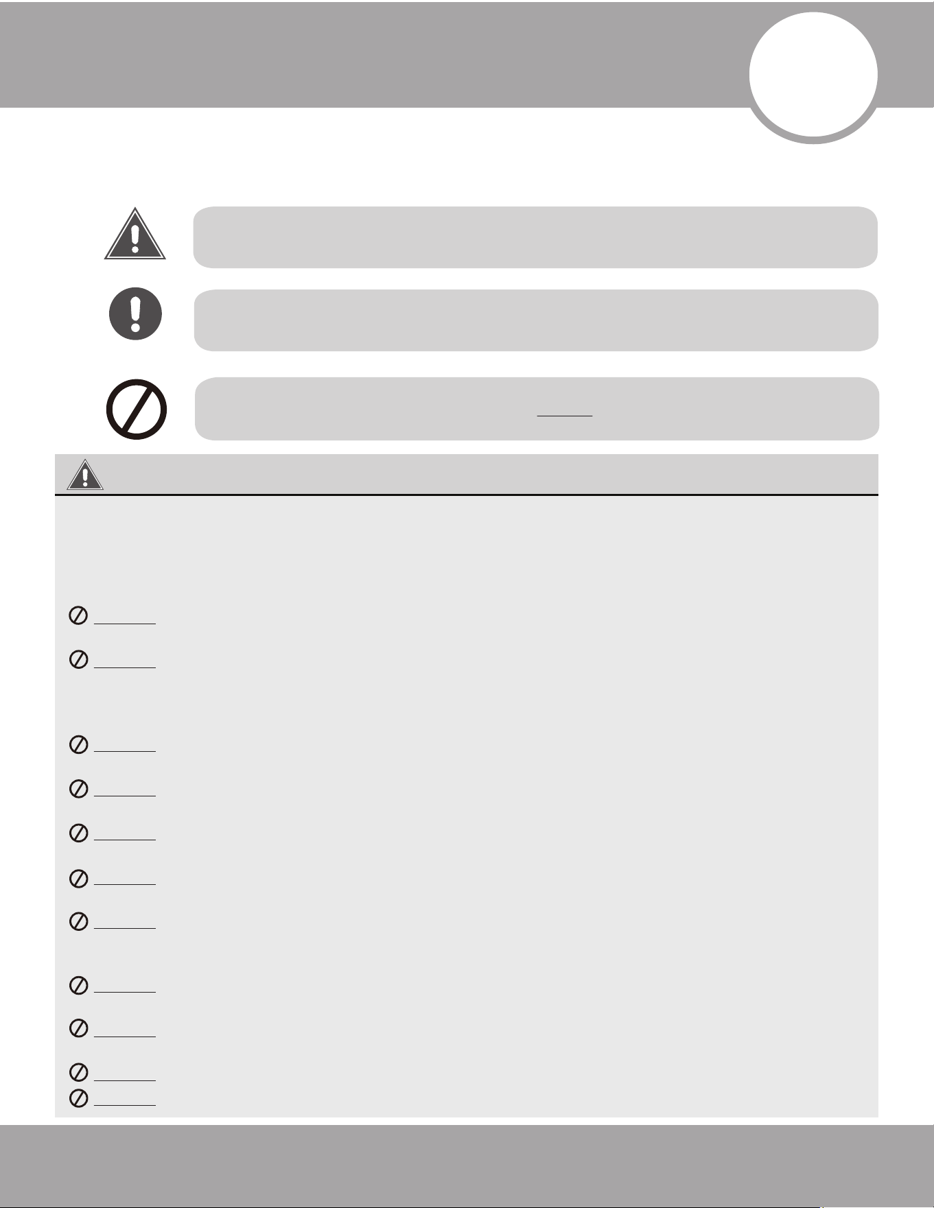
Safety Precautions
The symbols below are used throughout this manual to indicate instructions that should be
followed closely or actions that should be avoided to prevent death, injury, and/or property damage.
This symbol indicates ignoring instructions may cause bodily injury, damage
to the unit, or other surrounding property.
This symbol indicates ignoring instructions may cause death or serious injury.
This symbol indicates that you should NEVER perform the indicated action.
DISCLAIMER: You are assuming risk by handling materials containing refrigerants under
pressure, that if not handled properly can cause bodily injury. If you do not feel comfortable
performing this installation process, we recommend you retain the services of a qualified HVAC
professional.
****ELECTRICAL WORK MUST BE COMPLETED BY A QUALIFIED ELECTRICAL TECHNICIAN****
DO NOT share the electrical circuit with other appliances. You must use an independent
power supply. An improper or insufficient power supply could cause fire or electrical shock.
DO NOT allow any substances or gases to enter the unit when connecting the refrigerant
piping. The presence of other gases or substances will lower the unit’s capacity, and may
cause abnormally high pressure during the operation cycle. This could cause an explosion
and/or injury.
DO NOT allow children to play with the air conditioner. Children should be supervised
around the unit at all times.
DO NOT insert your fingers, rods, or other objects into the air inlet or outlet. The fan within
the unit could be rotating at high speeds and could cause injury.
DO NOT use flammable sprays such as hair spray, lacquer, or paint near the unit. These
could cause fire and/or an explosion.
DO NOT operate the unit in places where it could be exposed to or near combustible gas.
Emitted gas could collect around the unit and cause an explosion.
DO NOT operate the unit in a room where it could be exposed to excessive amounts of water
(such as a bathroom or laundry room). Too much exposure to water can cause electrical
components to short circuit.
DO NOT expose your skin or body directly to the cool air coming from the unit for a
prolonged period of time.
DO NOT install the unit within 3 ft (1 m) of any combustible gas if the unit is equipped with an
auxiliary heater.
DO NOT operate the air conditioner with wet hands. This could cause electrical shock.
DO NOT turn on the power until the installation has been completed.
Safety Precautions
DO NOT pull the power cord to unplug the unit. Hold the plug firmly and pull it from the outlet.
Pulling directly on the cord can damage it, which could lead to fire and/or electric shock.
DO NOT modify the length of the power supply or use an extension cord to power the unit.
1. Installation must be performed according to the installation instructions. Improper installation
could cause water leakage, electrical shock, fire, and could void the warranty.
2. If the unit operates abnormally (emits strange noises or a burning a smell), immediately turn off the
unit and disconnect the power in order to avoid electric shock, fire, and/or injury. Call your local
dealer, or MRCOOL tech support at (270) 366-0457, for further assistance.
3. In North America, service or repair must be performed in accordance with the requirements of NEC
and CEC (by authorized personnel or authority having jurisdiction only). Contact an authorized
service technician for repair or maintenance of the unit.
4. Only use the included accessories and specified parts for installation. Using non-standard parts can
cause water leakage, electrical shock, fire, and may cause the unit to fail.
5. Install the unit in a firm, stable location that can support its weight. If the installation location cannot
support the weight of the unit, it could fall and cause serious injury and/or damage.
6. Appropriate wiring standards, regulations, and the installation manual must be followed for all
electrical work.
7. If connecting power to fixed wiring, the following must be incorporated within it, in accordance with
the wiring rules; an all-pole disconnection device (which has at least 3 mm of clearances in all poles),
and have a leakage current that may exceed 10 mA, the residual current device (RCD) having a rated
residual operating current not exceeding 30 mA, all must be present.
8. For all electrical work, fuse the specified cables. Connect cables tightly and clamp them securely to
prevent external forces from damaging the terminal. Improper electrical connections could overheat,
causing fire and/or electrical shock.
9. All wiring must be properly arranged to ensure that the control board cover can close properly. If the
control board cover is not closed properly, it can lead to corrosion, which can cause the connection
points on the terminal to overheat, which could result in fire and/or electric shock.
10. In certain functional environments (such as kitchens and server rooms etc.), the use of specially
designed air-conditioning units is highly recommended.
11. If the supply cord is damaged, it must be replaced by the manufacturer, its service agent, or a similarly
qualified person in order to avoid a hazard.
12. This appliance can be used by children (8 years and older) and persons with reduced physical,
sensory or mental capabilities, or lack of experience and knowledge if they have been given
instruction concerning the use of the appliance and understand the hazards involved. Children
should not play with the appliance. Cleaning and user maintenance should not be performed by
children.
13. If the air conditioner is used together with burners or other heating devices, thoroughly ventilate
the room in order to avoid an oxygen deficiency.
14. Contact an authorized service technician for repair or maintenance of this unit.
15. Install drainage piping according to the instructions in this manual. Improper drainage may cause
water damage to your home and property.
16. When moving or relocating the air conditioner, consult experienced service technicians for
disconnection and re-installation of the unit.
17. The product must be properly grounded during installation or electrical shock could occur.
18. For more information on how to install the appliance to its support, please refer to the indoor unit
installation and outdoor unit installation sections of this manual.
19. Keep the power plug clean and remove dust or grime that accumulates around the plug. A dirty plug
could cause fire or electric shock.
WARNING
Page 4mrcool.com
Page 5
Safety Precautions
mrcool.com
Note about Fluorinated Gases:
1. This unit contains fluorinated greenhouse gases.
2. For specific information on the type of gas and the amount, please refer to the relevant label on
the unit itself.
3. Service, maintenance, and repair of this unit must be performed by a certified technician.
4. Product un-installation and recycling must be performed by a certified technician.
5. For equipment that contains fluorinated greenhouse gases in quantities of 5 tonnes of CO
2
equivalent or more, but less than 50 tonnes of CO
2
equivalent, and has a leak-detection system
installed, it must be checked for leaks at least every 24 months.
6. Keeping a record of all leak checks for the lifetime of the unit is strongly recommended.
CAUTION
DO NOT allow the air conditioner to operate for extended periods of time with the doors or
windows open, or in very high humidity.
1. Turn off the air conditioner and disconnect the power if it is not going to be used for an
extended period of time.
2. Turn off and unplug the unit during storms.
Page 6
Safety Precautions
mrcool.com
Electrical
Access
Front Panel
Wall Mounting Plate
Fresh Air Filter
Air inlet rear
Air inlet si e
Air outlet
Air outlet bottom
Outdoor Unit
(Exterior/Condenser)
Air inlet rear
Electrical Access
Air Filter
The installation must be performed in accordance with the requirement of local and national
standards. The installation may be slightly different in different areas.
NOTE ON ILLUSTRATIONS
Illustrations in this manual are for explanatory purposes. The actual shape of your unit may vary.
1
Parts Overview
Indoor Unit
(Interior/Air Handler)
Quick Connect® Line Set
(refrigerant pipe)
Pat. https://mrcool.com/mrcool-patents/
Fig. 1.1
NOTE
MC Cable
NOTE ON INSTALLATION OF A DIY MULTI-ZONE SYSTEM
Please read this instruction manual fully before you attempt to
install this system. Because there are multiple units, pipes, and
lines to be installed in different locations, and heating/cooling
zones to consider, planning your installation is necessary in order
to help prevent any potential problems. Taking proper
measurements is also vital to determine the line set lengths
needed to connect the indoor units to the outdoor unit. If you find
the standard line set length is not sufficient for your application,
you may need to purchase additional line sets and coupler kits. It
should be noted that it is easier to install the air handlers to the
outer walls. If they are to be mounted to interior walls, line sets
will need to be run to a central location, such as an attic,
basement, or crawlspace, and have them exit the house (to the
outdoor unit) from that location.
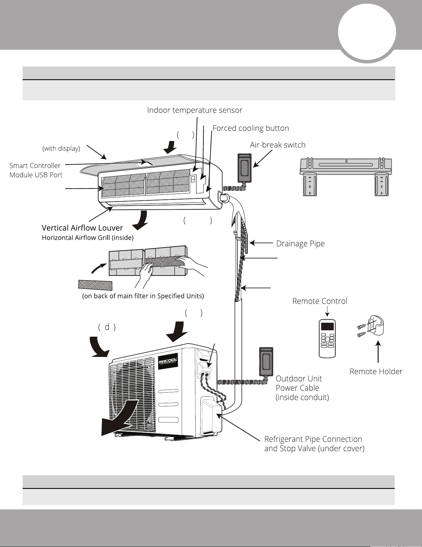
Indoor unit
1. Panel frame
2. Rear air intake grill
3. Front panel
4. Air purifying filter & Air filter (behind)
5. Horizontal louver
6. LCD display window
7. Vertical louver
8. Manual control button (behind front panel)
9. Remote controller holder
Outdoor unit
10. Drain hose, refrigerant connecting pipe
11. MC cable
12. Stop Valve
13. Fan hood
Page 7
Overview - Diagram
mrcool.com
Air Inlet
Air Inlet
Air Outlet
Outdoor
Unit
Refrigerant
Piping & Lines
Indoor Units within their zones
13
Fig. 1.2
One-five
One-four
One-three
One-two
Overview - Indoor Unit Display
mrcool.com
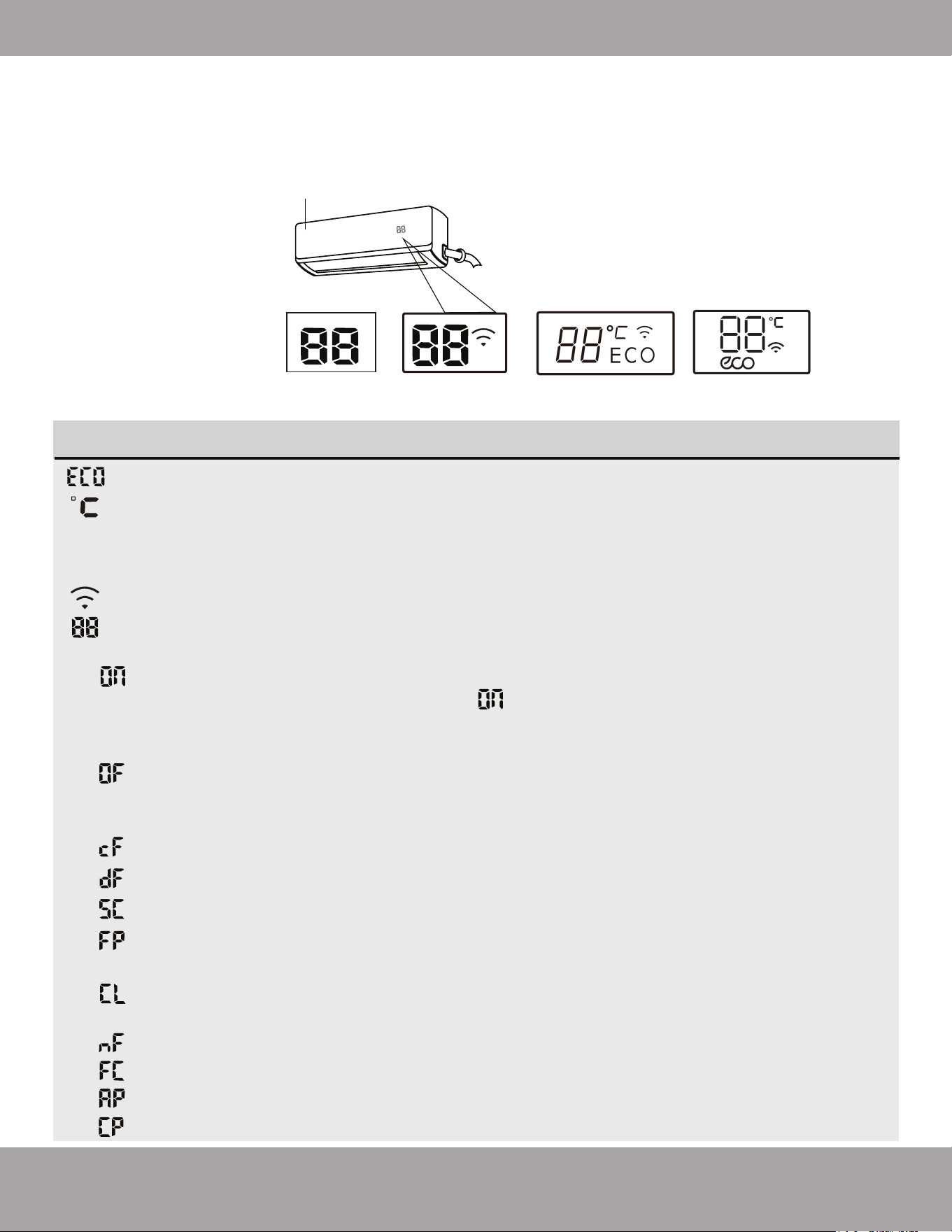
Display Code Meanings
Page 8
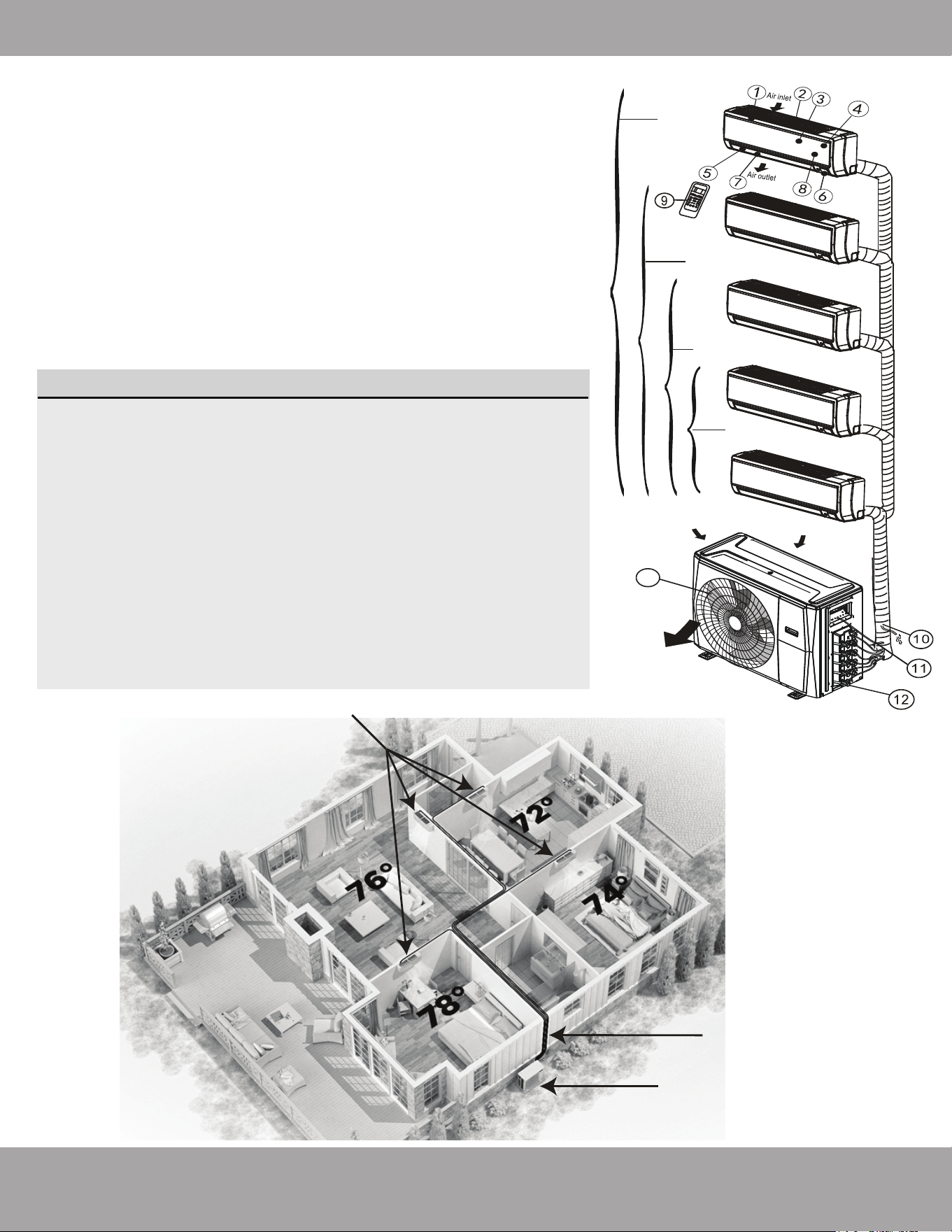
NOTE: Different models will have a different front panel and display window. Not all of the features
listed below will be equipped on the unit you have purchased. Please check the indoor unit display
window of the unit purchased to see which of these features your unit has.
Illustrations in this manual are for explanatory and demonstration purposes only. The actual shape
of your and size of your indoor unit may be different.
Fig. 1.3
Front Panel
Different Versions
of The Display
Window
(A)
(B)
(C)
(D)
When ECO function is activated (some units)
Units of measure, displays as either °C (Celcius) or °F (Fahrenheit). It will display in a
different color depending on the mode the unit is operating in:
• Under COOL or DRY mode, it will display as a cool color (Blue).
• Under HEAT mode it will display as a warm color (Red).
This will display when the Wireless Control feature is activated (some units).
This is the temperature display and will also display operational features and error
codes:
will display for 3 seconds when:
• TIMER ON is set (if the unit is OFF, will remain on the display screen
when the Timer On is set).
• SWING, TURBO, SILENCE, or SOLAR PV ECO features are turned on.
will display for 3 seconds when:
• TIMER OFF is set.
• SWING, TURBO, SILENCE, or SOLAR PV ECO features are turned off.
will display when the anti-cold air feature is activated.
will display when the unit is defrosting (cooling & heating units).
will display when the unit is self-cleaning.
will display when the heating feature is activated in a room with a temperature
under 46.4°F (8°C).
will display as a filter cleaning reminder (power on display for 15 seconds) or when
the Active Clean function is occurring.
will display as filter replacement reminder (power on display for 15 seconds).
when forced cooling is activated.
AP mode of WIFI connection.
will display when the remote controller is switched off.
Page 9
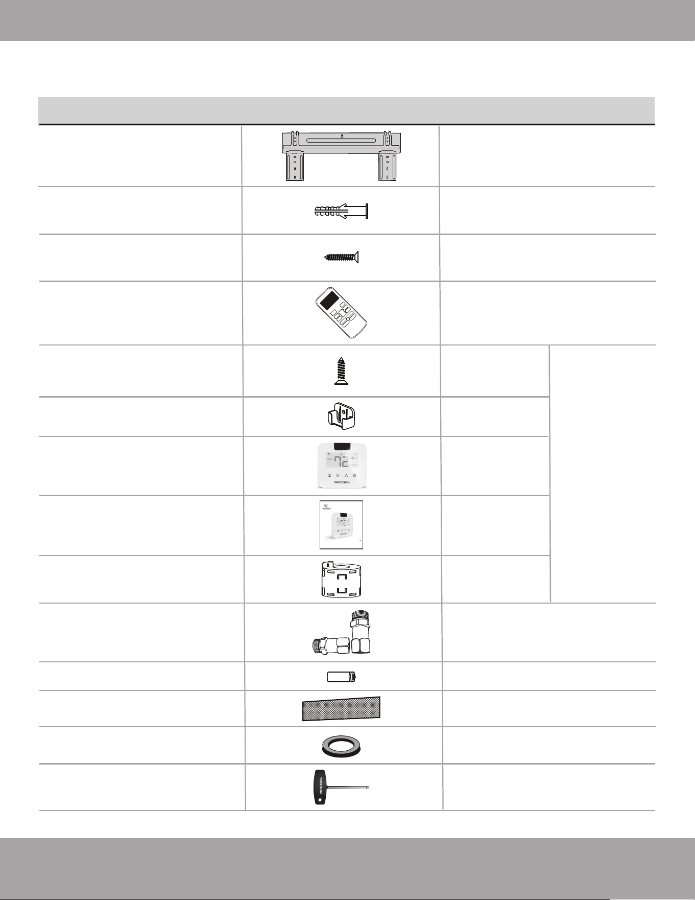
Accessories
mrcool.com
Optional
Parts
Note: Illustrations are for explanatory purposes only - The actual shape and size may vary.
The listing below shows the accessories and parts (these may vary depending on purchase
& options). Use all of the installation parts and accessories to install the system. Improper
installation may result in water leakage, electrical shock, fire, and/or equipment failure.
1
(in Mini
Stat™ Box)
MRCOOL
®
Mini-Stat™
1
(in Mini
Stat™ Box)
MRCOOL
®
Mini-Stat™
User Manual
MRCOOL Mini-Stat
User Manual
Magnetic Ring
Will vary based
on the number
of zones
Line-Set Adapter Set
(Included with
4-zone & 5-zone systems only)
1 liquid side adapter and 1
suction side adapter used for
installing indoor units rated
24K BTU or greater.
Batteries
2
Air Freshening Filter
1~2
(depending on model)
Seal
(for cooling & heating models)
1
Allen Wrench
®
1
Mounting plate
Anchors
Mounting plate screws
Remote control
Fixing screw for
remote controller
holder (optional)
Remote control
holder (optional)
1
5~8
(depending on models)
5~8
(depending on models)
1
2
1
PART LOOKS LIKE... QUANTITY
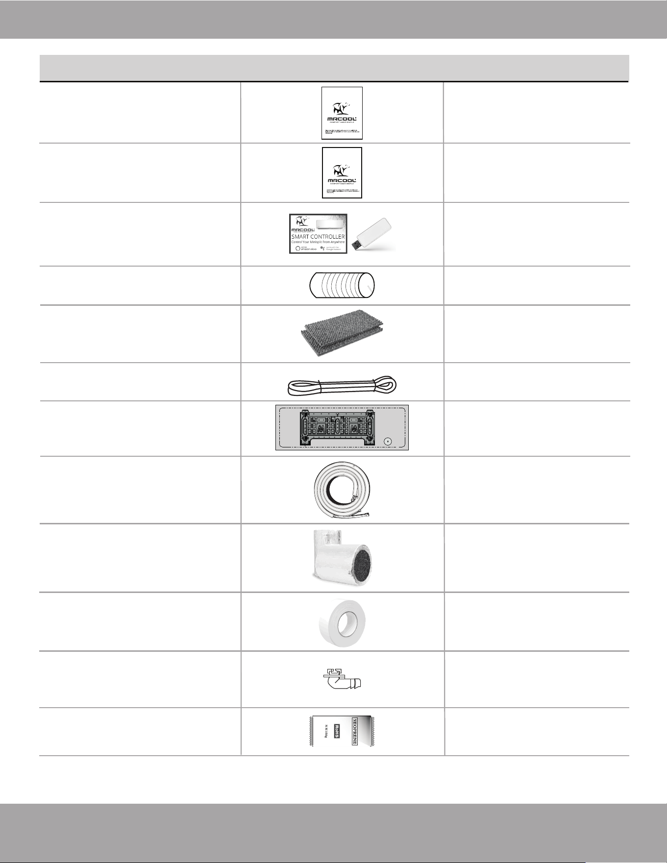
Page 10mrcool.com
Accessories
*Pat. https://mrcool.com/mrcool-patents/
QUANTITYPART LOOKS LIKE...
Installation & Owner’s
Manual
Remote Control
Manual
Smart Controller Kit
Sound Deadening
Pads
Quick Connect
®
Line Set (refrigerant pipe)*
Insulation Material
Non-Adhesive U.V. Tape
Plastic Wall Sleeve
Drain Pipe
Cardboard
Mounting Plate
Template
1
1
1
2
(Apply to the quick
connectors of the pipe)
1
2
1
(w/ Manual in
Controller Box)
1
1
16 ft (5 m)
1
1
(Only for use
when elevated)
Neoprene
Drain joint
1
(Sealant for Wall Sleeve)
Please read this manual carefully before installation and keep it for future reference.
Owner’s Manual
E-Star™ DIY
Series
For more details visit www.MrCool.com
For more details visit www.MrCool.com
Please read this manual carefully before installation and keep it for future reference.
Remote Control
User Manual
Page 11
Safety Precautions
mrcool.com
CAUTION
Manual Operation (without remote)
Operating Temperature Ranges
Fig 2.1
2
Operating Instructions
DRY Mode
HEAT Mode
COOL Mode
Room
Temperature
62°F - 90°F
(17°C - 32°C)
32°F - 122°F
(0°C - 50°C)
5°F - 122°F
(-15°C - 50°C)
18K-36K
-13°F - 75.2°F
(-25°C - 24°C)
32°F - 86°F
(0°C - 30°C)
50°F - 90°F
(10°C - 32°C)
Outdoor
Temperature
NOTES:
• If the air conditioner operates for extended periods in cooling mode and the humidity
is high (over 80%), condensed water may drip out of the unit. If this occurs, set the vertical
airflow louver to its maximum angle (vertical toward the floor), and set it to HIGH fan mode.
• Optimum performance will be achieved within the above operating temperatures. If the air
conditioner is operated outside of the above temperatures, certain safety protection features
might be activated and cause the unit to function abnormally.
• FOR OUTDOOR UNITS WITH AUXILIARY ELECTRIC HEATER: When the outside temperature
is below 32°F (0°C), we strongly recommend keeping the unit plugged in at all time to ensure
smooth ongoing performance.
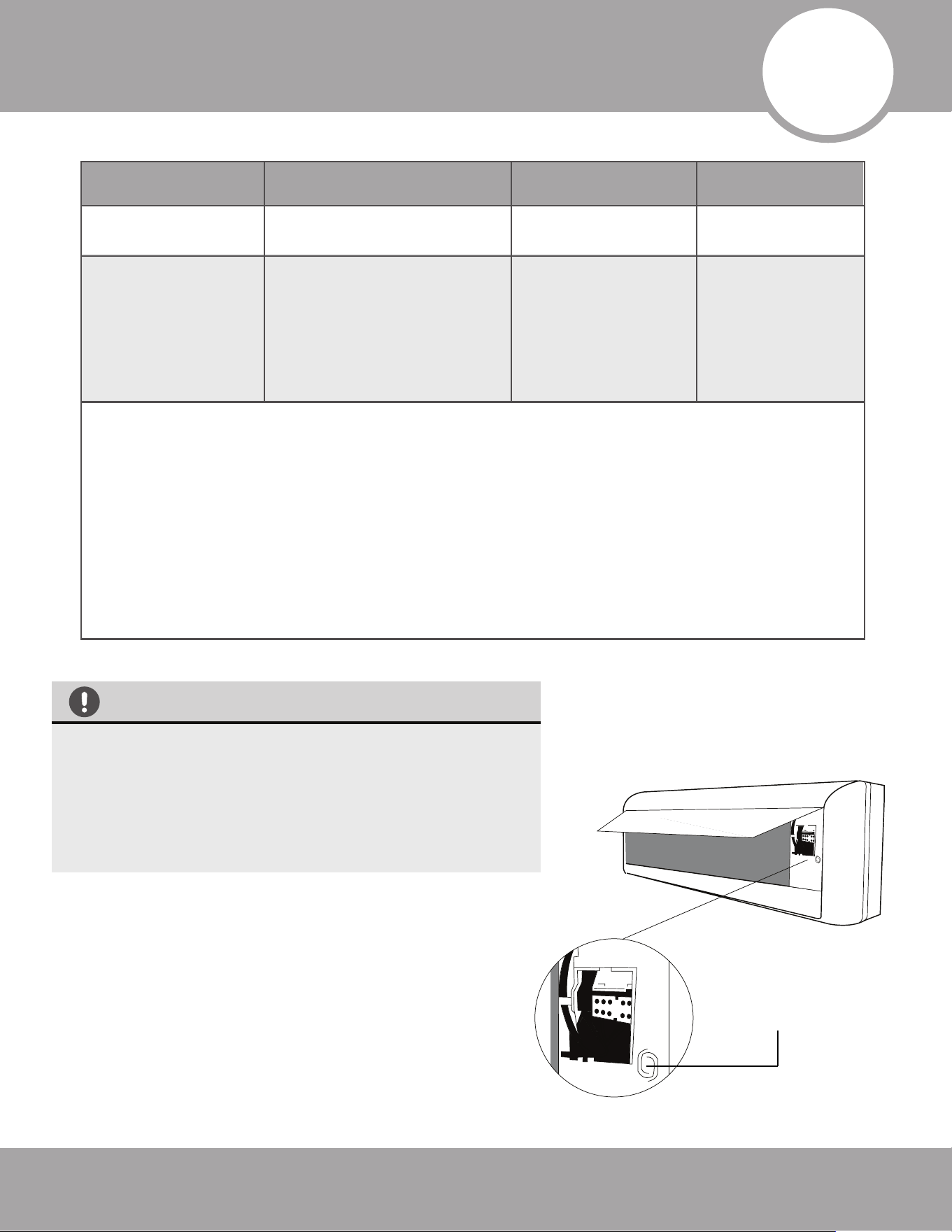
Manual control button
The manual control button is intended for testing purposes
and emergency operation only. Please do not use this
function unless the remote control is lost and it is absolutely
necessary. To restore regular operation, use the remote
control to activate the unit. THE UNIT MUST BE TURNED
OFF BEFORE THE MANUAL OPERATION FUNCTION CAN
BE ACTIVATED.
To operate the unit manually, follow these steps:
1. Open the front panel of the indoor unit.
2. Locate the MANUAL CONTROL BUTTON on the
right-hand side of the unit.
3. Press the MANUAL CONTROL BUTTON one time to
activate the FORCED AUTO MODE.
4. Press the MANUAL CONTROL BUTTON a second time to
activate the FORCED COOLING FUNCTION.
5. Press the MANUAL CONTROL BUTTON a third time to
turn the unit off.
6. Close the front panel.
48K
5°F - 75.2°F
(-15°C - 24°C)
Page 12
Operating Instructions
mrcool.com
Range
Fig. 2.3
Horizontal Louver
(Horizontal Airflow
Grill inside)
Vertical
Louver
Range
Fig. 2.2
Horizontal
CAUTION
DO NOT put your fingers into the panel of
the blower and suction side. The high speed
fan inside may cause injury.
DO NOT operate the unit for extended
periods of time in COOL or DRY mode with
the vertical airflow direction set with too
much of a downward angle. This could
cause condensation to form on the surface
of the vertical louver and allow moisture/
water droplets to drop onto furnishings or
the floor.
DO NOT move the vertical louver manually,
as this could cause it to become out of sync.
If this occurs, follow these steps:
1. Turn off the power to the unit.
2. Remove the wireless module from the
back of the front cover.
3. Turn off the power to the circuit at the
breaker.
4. Wait a few seconds and turn the power
back on at the breaker.
5. Reinstall the wireless module into the
front cover.
6. Turn the power to the unit back on.
NOTE: After a quick restart, the vertical louver
may remain static for approximately
10 seconds.
NOTE: The open angle of the vertical louver
should not be set too small when using COOL or
HEAT mode, as it will restrict airflow and reduce
performance of the unit.
·
·
·
Louver
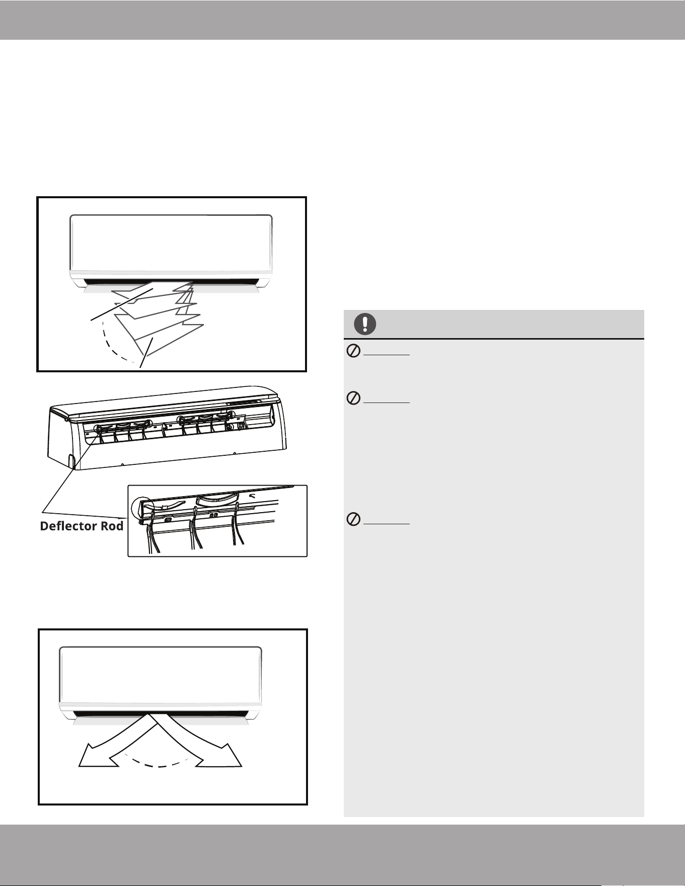
Adjustment of the vertical and horizontal louvers
will change airflow direction of the indoor unit to
prevent discomfort and/or uneven room
temperatures.
Adjust the vertical louver using the remote.
Adjust the horizontal louver manually by
hand.
Fig. 2.4
Adjust Vertical Airflow (Up/Down) using Vertical
Louver (Fig 2.2):
This function is performed by using the
SWING/DIRECT button on the remote control, while
the unit is operating. The Vertical louver can move in
small increments for each press, or continuously
swing up and down automatically. Please refer to the
“Remote Control User Manual” for further details.
Adjust Horizontal Airflow (Left/Right) using
Horizontal Louver (Fig 2.3 & Fig 2.4)
The angle of the horizontal louver must be set
manually. Move the deflector rod, located on the
underside of the unit, by pushing the tab to manually
adjust the airflow from side to side as desired. For
some units, the horizontal angle of the airflow can be
set by the remote control. Please refer to the
“Remote Control User Manual” for further details.
Airflow Directional Control
When ECO function is activated (some units)
Units of measure, displays as either °C (Celcius) or °F (Fahrenheit). It will display in a
different color depending on the mode the unit is operating in:
• Under COOL or DRY mode, it will display as a cool color (Blue).
• Under HEAT mode it will display as a warm color (Red).
This will display when the Wireless Control feature is activated (some units).
This is the temperature display and will also display operational features and error
codes:
will display for 3 seconds when:
• TIMER ON is set (if the unit is OFF, will remain on the display screen
when the Timer On is set).
• SWING, TURBO, SILENCE, or SOLAR PV ECO features are turned on.
will display for 3 seconds when:
• TIMER OFF is set.
• SWING, TURBO, SILENCE, or SOLAR PV ECO features are turned off.
will display when the anti-cold air feature is activated.
will display when the unit is defrosting (cooling & heating units).
will display when the unit is self-cleaning.
will display when the heating feature is activated in a room with a temperature
under 46.4°F (8°C).
will display as a filter cleaning reminder (power on display for 15 seconds) or when
the Active Clean function is occurring.
will display as filter replacement reminder (power on display for 15 seconds).
when forced cooling is activated.
AP mode of WIFI connection.
will display when the remote controller is switched off.
Page 13
Operating Instructions
mrcool.com
hour
hour
Set
Temperature
SLEEP Operation While Cooling
SLEEP operation
8 hours
timer OFF
Set
Temperature
hour
hour
SLEEP operation
8 hours
timer OFF
SLEEP Operation While Heating
Optimal Operation
How the Air Conditioner Works
Basic Operation Modes:
AUTO / COOL / DRY / HEAT (Model Dependent).
AUTO Mode:
When you set the unit in AUTO mode, it will automatically
select COOL, HEAT, or FAN-ONLY mode depending on
the set temperature and the room temperature.
The unit will control the room temperature automatically,
according to the temperature you set the unit to.
DRY Mode:
The temperature is regulated while dehumidifying by
intermittently switching the COOL or FAN-ONLY modes
on and off. The fan speed is set to LOW.
HEAT Mode:
The unit is a heat pump by design. By reversing the air
conditioning process, it absorbs heat from the outdoors
and transfers it to the indoor unit. At the same time, heat
loading of the air conditioner increases due to larger
differences between the indoor and outdoor temperature.
As a result, the operating performance and efficiency is
reduced as the outdoor air temperature drops. If you feel
that the heating performance is insufficient, it is
recommended that you supplement heating with other
appliances.
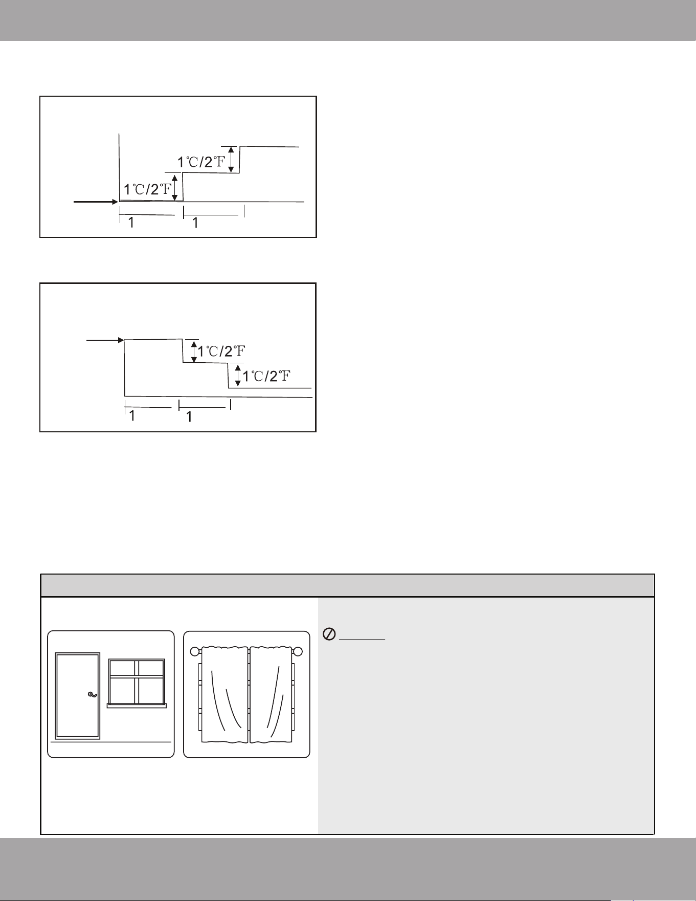
SLEEP Mode (Fig. 2.5 & Fig. 2.6):
The SLEEP function is used to decrease energy use while
you sleep. During sleep you do not need the same
temperature settings to stay comfortable. This function can
only be activated via the remote control. The SLEEP
function is not available in FAN or DRY modes.
When SLEEP mode is activated, the temperature will
increase while cooling, or decrease while heating by, 2°F
(1°C) per hour for the first 2 hours. Thereafter, it keeps this
new temperature for 6 hours before SLEEP mode will
automatically switch off.
To achieve optimal performance, please note the
following:
DO NOT put any objects near the air inlets &
outlets. Doing this would impair performance and
could cause the unit to shut down.
• Adjust the airflow direction of the louvers
correctly, so that it is not towards people or at an
extreme angle/closed.
• Adjust the temperature to achieve moderate
comfort levels. An excessively low or high
temperature setting wastes energy.
• Keep windows and doors closed, as this will
improve performance.
• Limit energy usage (run time) using the TIMER
function and SLEEP/ECONOMY mode if applicable.
• Regularly inspect and clean the air filters.
Doors and windows
should be kept
closed.
Closing the curtains
while heating also
helps keep the heat in
Fig. 2.5
Fig. 2.6

Page 14
Operating Instructions
mrcool.com
While two or more indoor units are operating simultaneously, make sure the modes selected on each of the
units do not conflict with one another. The HEAT mode claims precedence over all of the other modes. If the
unit initially started to operate in HEAT mode, the other units can only operate in HEAT mode. For example: If
the unit initially started to operate under COOL or FAN mode, the other units can operate under any mode
except HEAT. If HEAT mode is selected on one of the units, the other units will cease operating, and one of
the following will occur, depending on the model:
Special Functions
Refrigerant Leakage Detection (optional):
When a refrigerant leakage is detected, the indoor unit will display an “EC” or “ELOC“ code or flash LEDs
(depending on model).
Louver Angle Memory Functions (optional):
If the horizontal louver is within the safe operation angle, the system will remember the last position selected
by the user and return to it. If the louver is in a position that exceeds the safe operation angle, it will default to
a position that is within the safe operation range. However, it will not return to a safe operation angle when
TURBO mode is activated, the unit is in manual control mode, or after a power interruption. Subsequently, it
is strongly recommended that the horizontal louver angle not be set too small in order to avoid possible
condensation leakage.
Anti-Cold Air Function (Cooling and Heating models only):
The unit is designed to not blow cold air while in HEAT mode, when the indoor heat exchanger is in one of the
following situations and the set temperature has not been reached.
• When the unit has just begun heating.
• While the unit is defrosting.
• Low temperature heating.
Defrosting Function (cooling and heating models only)
Frost may be generated on the outdoor unit during a heat cycle, when the outdoor temperature is low and
the humidity is high. This results in lower heating efficiency by the unit. Under these conditions, the air
conditioner will stop heating operations and will begin defrosting automatically. The time to defrost may vary
from 4 to 10 minutes, depending on the outdoor temperature and the amount of frost buildup on the
outdoor condenser. NOTE: During defrosting, the indoor and outdoor fans will stop spinning.
Anti-Mildew Function (some units):
When the unit is turned off when in COOL, DRY, or, AUTO modes, it will continue to operate at very low
power. This is to aid in drying any condensation that has formed inside the unit to prevent mildew growth.
Auto-Restart (some units):
In the event of a power interruption, such as a blackout, the unit will stop. It will then restart automatically and
resume the previous operation when the power supply returns. NOTE: In order to protect the
compressor, once it stops it cannot be restarted for 3 minutes.
Wireless Smart Control Function:
Connect the wireless control module via the USB port in the back of the front cover of the indoor unit. This
will allow the unit to be controlled by the remote control and/or the smartphone app. For the USB device
access, replacement, and maintenance operations must be carried out by a professional staff.
For models equipped with a display window only- This “--” will appear in the display window.
For units without a display window- The auto and operation indication light will flash rapidly,
the defrost indication light will turn off, and the timer indication light will remain on.
.
.
Operation Mode Selection

Page 15
Operating Instructions
mrcool.com
Mute Function (optional):
Press the LED button on the remote control to turn off the LED display and silence the buzzer of the indoor
unit to create a quiet environment.
Operating Instructions
mrcool.com
Tab
1
2
3
Care and Maintenance
Cleaning the Unit:
Wipe the unit with a soft dry cloth. If the unit is very dirty, wipe it
with a cloth soaked in warm water.
DO NOT use bleach or abrasives.
NOTE: A clogged air filter can greatly reduce heating and
cooling efficiency of this unit. It is recommended to clean
the unit every 2 weeks.
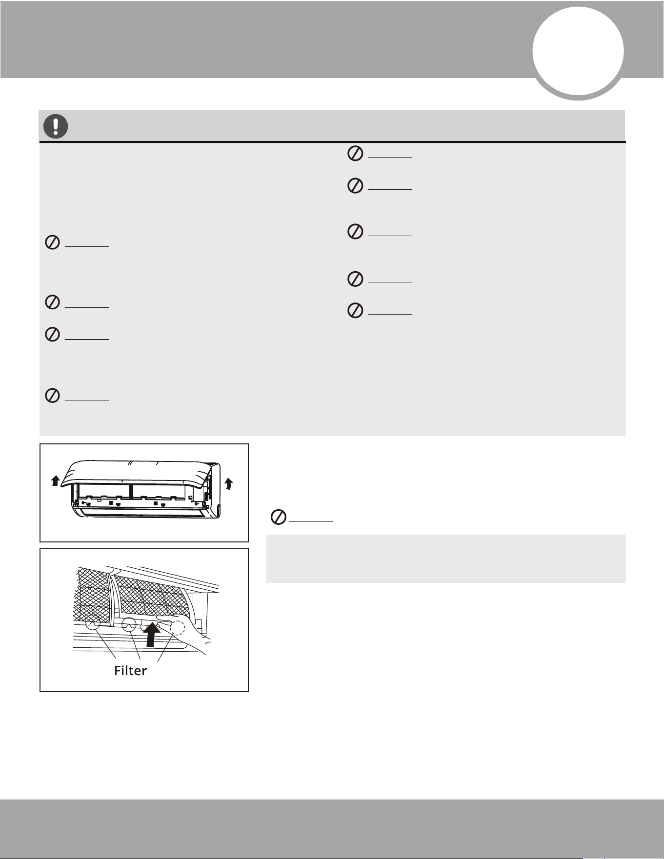
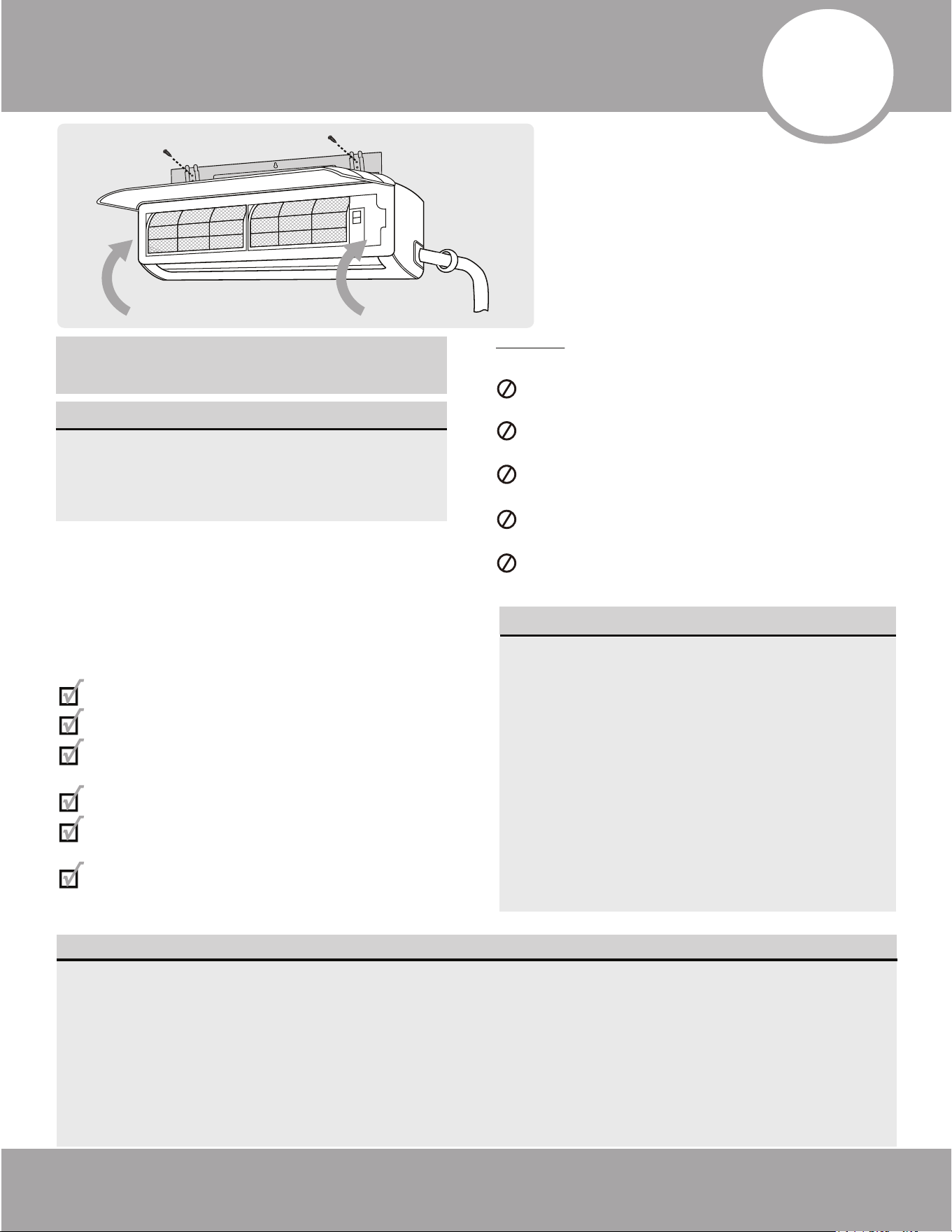
Cleaning the Air FIlter & Air Freshener:
1. Open the front by carefully lifting both ends at the same time.
As you continue lifting, at a certain angle there will be an audible
click and the lid will become self-supporting. Some models are
equipped with suspension bars that are required to prop the lid
open.
2. Use the filter tabs to lift filter slightly upward and then pull it
toward you.
The power supply must be disconnected before
attempting any kind of cleaning or service.
Before performing maintenance, turn the power
off to the unit and then disconnect the power to
the circuit at the breaker. Failure to do this could
cause electrical shock and injury.
DO NOT use benzene, thinner, polishing
powder, or similar solvents for cleaning.
These could cause the plastic to deform
and/or crack.
DO NOT clean the unit with excessive
amounts of water.
DO NOT touch the metal parts of the
unit when removing the filter. Injuries
can occur when handling the sharp metal
edges.
DO NOT use water to clean the inside of the
unit. Exposure to water can destroy the
insulation, which could lead to electric shock.
DO NOT use a chemically treated cloth or
duster to clean the unit.
DO NOT touch the air freshening (Plasma)
filter for at least 10 minutes after turning
off the unit.
DO NOT clean the unit with combustible
cleaning agents. These could cause fire
and/or deformation of the unit.
DO NOT wash the air filter with water
hotter than 104°F (40°C).
DO NOT expose the filter to direct sunlight,
as this could cause it to shrink. Allow the
filter to dry in the shade.
Page 16
mrcool.com
CAUTION
Page 17
Care and Maintenance
mrcool.com
Panel buckles
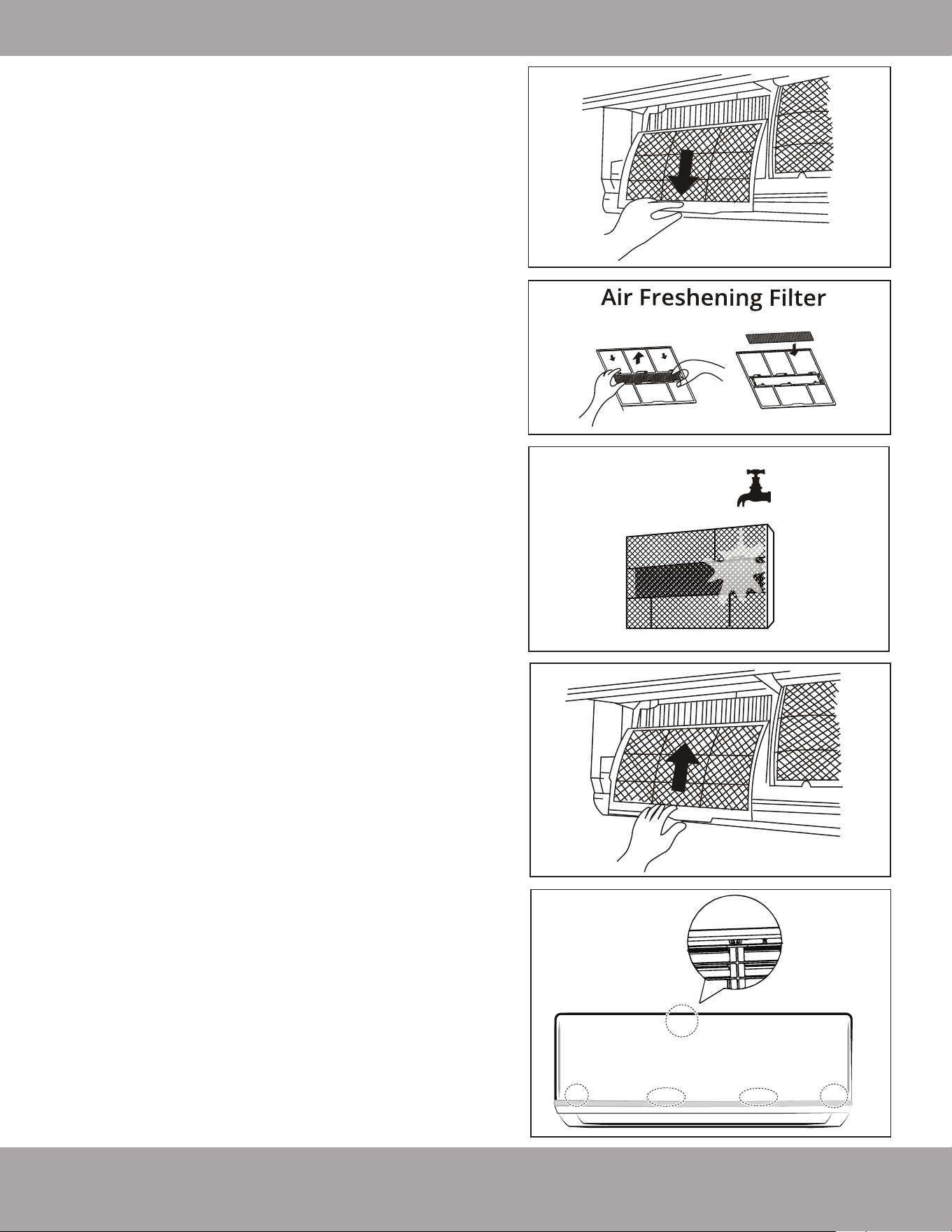
3. Then, extract the filter by gently drawing it
downward. Replace as necessary.
4. Unclip the small air freshening filter from the larger
air filter. Replace if necessary. Otherwise, clean it
with a vacuum and clip it back into place after
cleaning the larger air filter as outlined in step 5.
5. Clean the large air filter with warm, soapy water. Be
sure to use a mild detergent and rinse with fresh
water. Shake off the excess water and allow it to dry
in a cool area.
6. Re-clip the small air freshening filter into the large air
filter by reversing step 4.
7. Re-fit air filter back into the unit by reversing steps 2
and 3 by gently pushing the top of the filter up into
the unit and then lowering the bottom portion into
place.
8. Close the front panel of the unit. Make sure that it
buckles securely and the panel is completely closed.
Preparation for Extended Non-Operation:
If you plan to not run the unit for an extended period of
time (e.g. from the end of summer to the beginning of
the following summer), perform the following:
1. Clean the indoor unit and filters as outlined in the
previous steps.
2. Operate the unit in FAN-Only mode for at least 8
hours to dry out the inside of the unit.
3. Turn off the unit. Then, turn off the power to the
circuit at the breaker. The unit should be the only
appliance on this circuit.
4. Remove the batteries from the remote control.
5. The outdoor unit also requires periodic maintenance.
However, it is highly recommended you contact a
qualified service professional to perform this. Please
do not attempt to do this on your own.
Pre-Season Inspection:
After prolonged non-operation perform the following:
1. Use a dry cloth to wipe off any dust that has
accumulated on the rear air intake grille. This will
avoid any dust from being dispersed from the indoor
unit.
2. Check for any damaged or disconnected wires.
3. Clean or replace the filters and ensure they properly
installed.
4. Check for water and oil leaks.
5. Check for blockages in the airflow inlet and outlet.
6. Replace batteries in the remote control.
Removal
Install
5
3
4 & 6
7
8
Page 18
mrcool.com
•
CAUTION
•
To prevent wall damage, use a stud finder to
locate studs to mount the units to.
A minimum pipe run of 9.8 ft (3 m) is required to
minimize vibration & excessive noise.
Two of the A, B, and C air circulation pathways of
the outdoor unit must be free from obstructions
at all times (Refer to illustration).
This illustration is for demonstration purposes only.
The actual shape and size of your air conditioner
may vary.
NOTE: The installation of this system must be
performed in accordance with the requirements
of local and national standards. These could be
different based on the region it is being
installed in.
•
•
Safety Precautions
1
2
3
4
1
Installation plate
Mounting screw
ST3.9
× 25-C-H
Clip anchor
(1)
Remote
controller
holder
4 3 5
2
Air-break Switch
Drainage
Pipe
Air-break
Switch
Outdoor Unit
Power Cable
4
Installation Diagram
One-Two
One-Three
One-Four
One-Five
More than
24 in
(60cm)
More than
24 in
(60cm)
More
than 12 in
(30 cm)
More than
79 in
(200 cm)
More than
12 in
(30 cm)
More than
4.7 in (12 cm)
More than 6 in
(15 cm)
More than
4.7 in (12 cm)
More than
4.7 in (12 cm)
5
More than
4.7 in (12 cm)
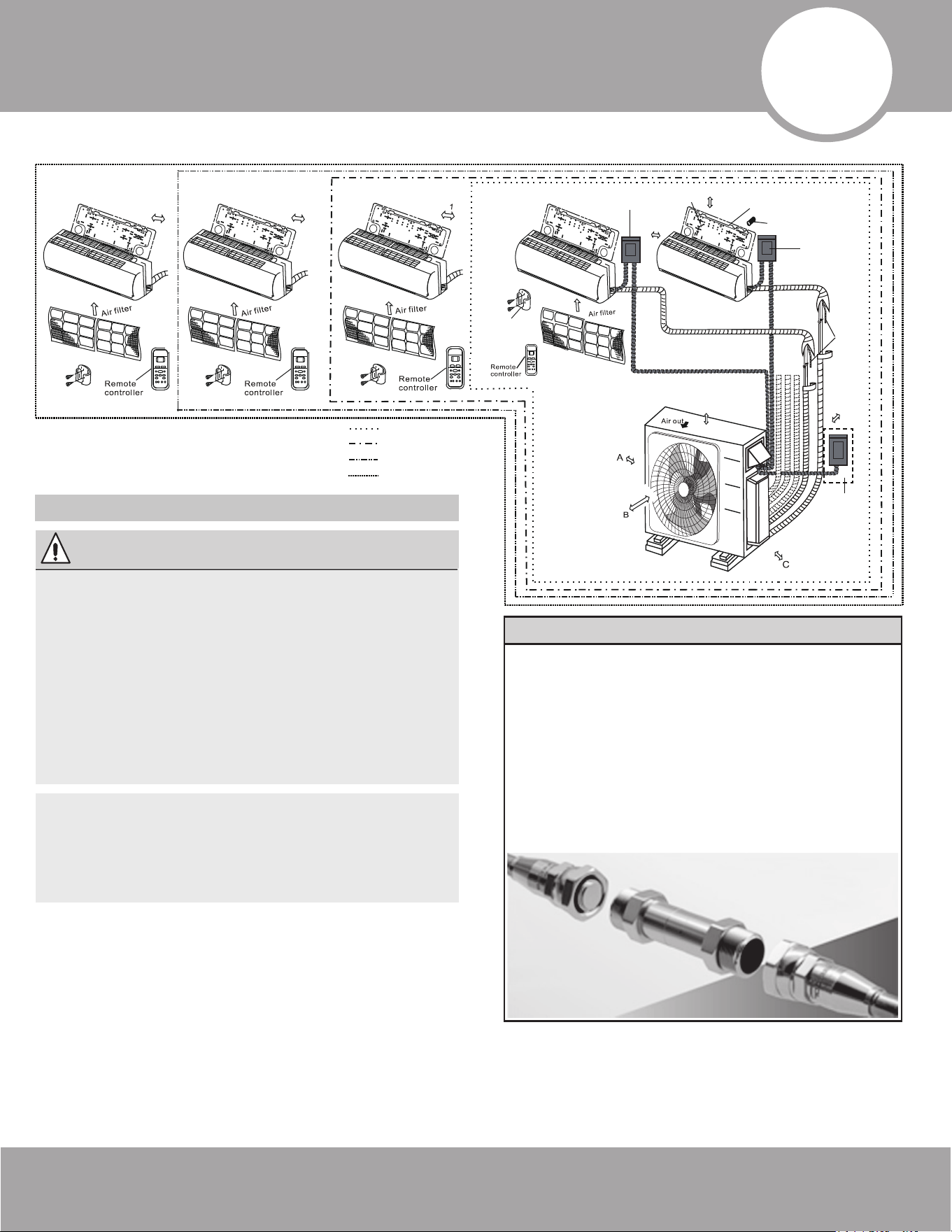
Additional Line Sets & Coupler Kit
If you find the default line set lengths are not
sufficient for your application, additional line
sets are available for purchase. You will also
need a coupler kit (pictured below), which
allows line sets to be connected together. The
coupler kit is installed and checked for leaks by
following the same steps described in this
manual for connecting the line set to the
indoor air handler (Refer to Section 7:
Refrigerant Piping Connections for these steps).
Fig. 4.1
Page 19
Installation Diagram
mrcool.com
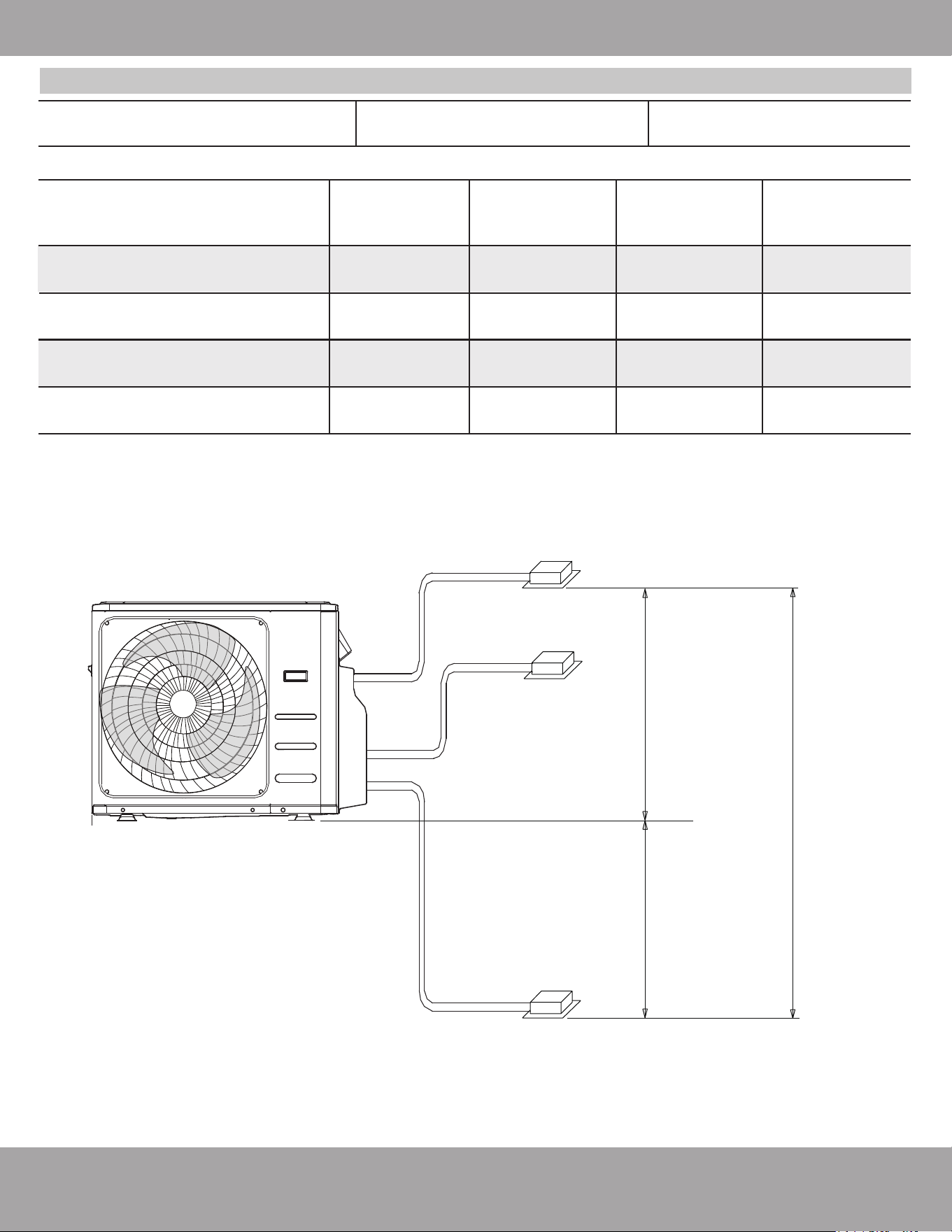
Number of units that can be
used together
Connected units 1-5 units
Unit: feet (meters)
When installing multiple indoor units with a single outdoor unit, ensure that the length of the
refrigerant pipe and the drop height between the indoor and outdoor units meet the requirements
illustrated in Fig. 4.2 below:
18K
2-Zone
Condenser
27K
3-Zone
Condenser
Max. combined line set
length for all rooms
123 ft
(37.5 m)
172.2 ft
(52.5 m)
Max. line set length
for one indoor unit
73.8 ft
(22.5 m)
73.8 ft
(22.5 m)
Max. height difference
between indoor & outdoor unit
32.8 ft
(10 m)
32.8 ft
(10 m)
Max. height difference
between indoor units
33 ft
(10 m)
33 ft
(10 m)
36K
4-Zone
Condenser
48K
5-Zone
Condenser
221.5 ft
(67.5 m)
73.8 ft
(22.5 m)
73.8 ft
(22.5 m)
221.5 ft
(67.5 m)
32.8 ft
(10 m)
49.2 ft
(15 m)
33 ft
(10 m)
33 ft
(10 m)
Line Set Length Specifications
33 ft (10 m)
Indoor unit
Indoor unit
Indoor unit Outdoor unit
18K-36K
Condenser
32.81 ft (10 m)
48K
Condenser
49.21 ft (15 m)
18K-36K
Condenser
32.81 ft (10 m)
48K
Condenser
49.21 ft (15 m)
Maximum Height
Difference
Fig. 4.2
Page 20mrcool.com
Installation Summary - Indoor Unit
Installation Instructions
– Indoor Unit
PRIOR TO INSTALLATION:
Before installing the indoor unit, refer to the
label on the product box to make sure that
the model numbers of the indoor unit and
the outdoor unit match.
Step 1: Selecting an installation location
Before installing the indoor unit, you must choose
an appropriate location. The following standards
and guidelines will help you choose an appropriate
location for the unit.
Proper installation locations should meet
the following standards
NOTE ABOUT WALL HOLE:
5
Indoor Unit Installation
If there is no fixed refrigerant piping:
While choosing a location, be sure that you
leave ample room for a wall hole (see the Drill
Wall Hole for Connective Piping step on the
following pages) for the signal cable and
refrigerant piping, which connect the indoor
and outdoor units. The default position for all
piping is the right-hand side of the indoor unit
(while facing the front of the unit). After the
piping and signal wire are installed, use the
provided neoprene (spray foam can be used
instead, if you prefer) to pack the space left in
hole, in order to seal it and make it airtight.
If you are planning on mounting air handlers to interior walls, there are some aspects that need to be
considered when it comes to drilling a wall hole and routing line sets to the outdoor condenser. If you are
not able to mount air handlers to exterior walls, you will need to run the line sets to a central location
within the house, such as an attic, basement, or crawlspace, and have them exit the house (to the
outdoor unit) from that location. Another aspect to consider is the condensate drain pipe. A drain pipe is
necessary to allow water (condensate) to exit the air handler. If you mount an air handler in a location
that is difficult to run a drain hose down and outside, it may be necessary to use a condensate pump (not
included, but available from online retailers). These are used to pump the water from the air handler and
prevent it from ruining the interior of your home.
NOTE ON MOUNTING AIR HANDLERS TO INTERIOR WALLS
Good air circulation
Convenient drainage
Noise from the unit will not disturb
other people
Firm & solid location that will not vibrate
Strong enough to support the weight of
the unit
A location that is at least 3.3 ft (1 m) from all
other electronic devices (e.g., TV, radio,
computer)
DO NOT install the indoor unit in any of the
following locations:
Near any source of heat, steam, or
combustible gas.
Near flammable items such as curtains
or clothing.
Near any obstacles that could block air
circulation.
Near a doorway or where outside air may
blow directly on the indoor unit.
In a location subject to direct sunlight
exposure.
mrcool.com
Indoor Unit Installation
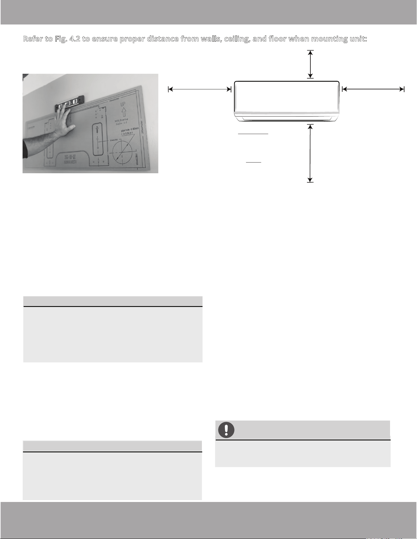
Refer to Fig. 4.2 to ensure proper distance from walls, ceiling, and floor when mounting unit:
NOTE FOR CONCRETE OR BRICK WALLS:
If the wall is made of brick, concrete, or a similar
material, drill 0.2 in (5 mm) diameter holes in the
wall and insert the sleeve anchors provided.
Secure the mounting plate to the wall by
tightening the screws directly into the anchors.
1.
2.
3.
CAUTION
When drilling the wall hole, be sure to
avoid wires, plumbing, nails, screws, and
other sensitive components.
Minimum Ceiling
Clearance
5.9 in (15 cm)
Minimum Side
Clearance
4.75 in (12 cm)
Minimum Side
Clearance
4.75 in (12 cm)
*For Ceilings GREATER than 9 ft.,
recommended distance from floor
90.55 in (230 cm)
*For Ceilings LESS than 9 ft.,
recommended distance from floor
78.55 in (200 cm)
Step 3: Drill Wall Hole for Connective Piping
You must drill a hole in the wall for the refrigerant
piping, drainage pipe, and signal cable to pass through
in order to connect the indoor and outdoor units.
Determine the location of the wall hole based on
the position of the mounting plate. Refer to the
Mounting Plate Dimensions (See Fig 5.5) to
assist you in determining the optimal position for
the hole, based on the type of mounting plate
provided with your unit.
Using a core drill, with a 3.54 in (90 mm)
diameter, drill a hole in the wall at a slight
downward angle, so that the indoor end of the
hole is higher than the outdoor end of the hole,
by approximately 0.2 in to 0.275 in (5 mm to 7
mm). This will ensure proper water drainage from
the indoor unit (See Fig. 5.3).
Insert the protective wall sleeve through the
hole of the inside wall, noting the amount it
protrudes from the exterior wall. Then, trim the
excess, with a utility knife or a saw, to make it
flush with the exterior wall. This will protect the
edges of the hole and help seal it when you
finish the installation process (See Fig 5.4).
Page 21
NOTE
A cardboard template of the mounting plate is
included to be used as a more manageable way of
determining where to mount the mounting plate
and drill the wall hole. It can be placed against the
wall in place of the actual mounting plate for the
previous step (See Fig 5.1).
Fig. 5.1
Step 2: Attach Mounting Plate to Wall
You must drill a hole in the wall for the refrigerant
piping, drainage pipe, and signal cable to pass
through in order to connect the indoor and outdoor
units.
1. Remove the screw that attaches the mounting
plate to the back of the indoor unit.
2. Place the mounting plate against the wall in a
location that meets the guidelines in the
Selecting an Installation Location step. Refer
to the Mounting Plate Dimensions section for
detailed information on mounting plate sizes.
3. Drill holes for wall plate mounting screws in places
that have the following:
• studs that can support the weight of the unit.
• correspond to the holes in the mounting plate.
4. Secure the mounting plate to the wall with the
supplied screws.
5. Make sure that the mounting plate is flat against
the wall.
Fig. 5.2
Page 22mrcool.com
Indoor Unit Installation
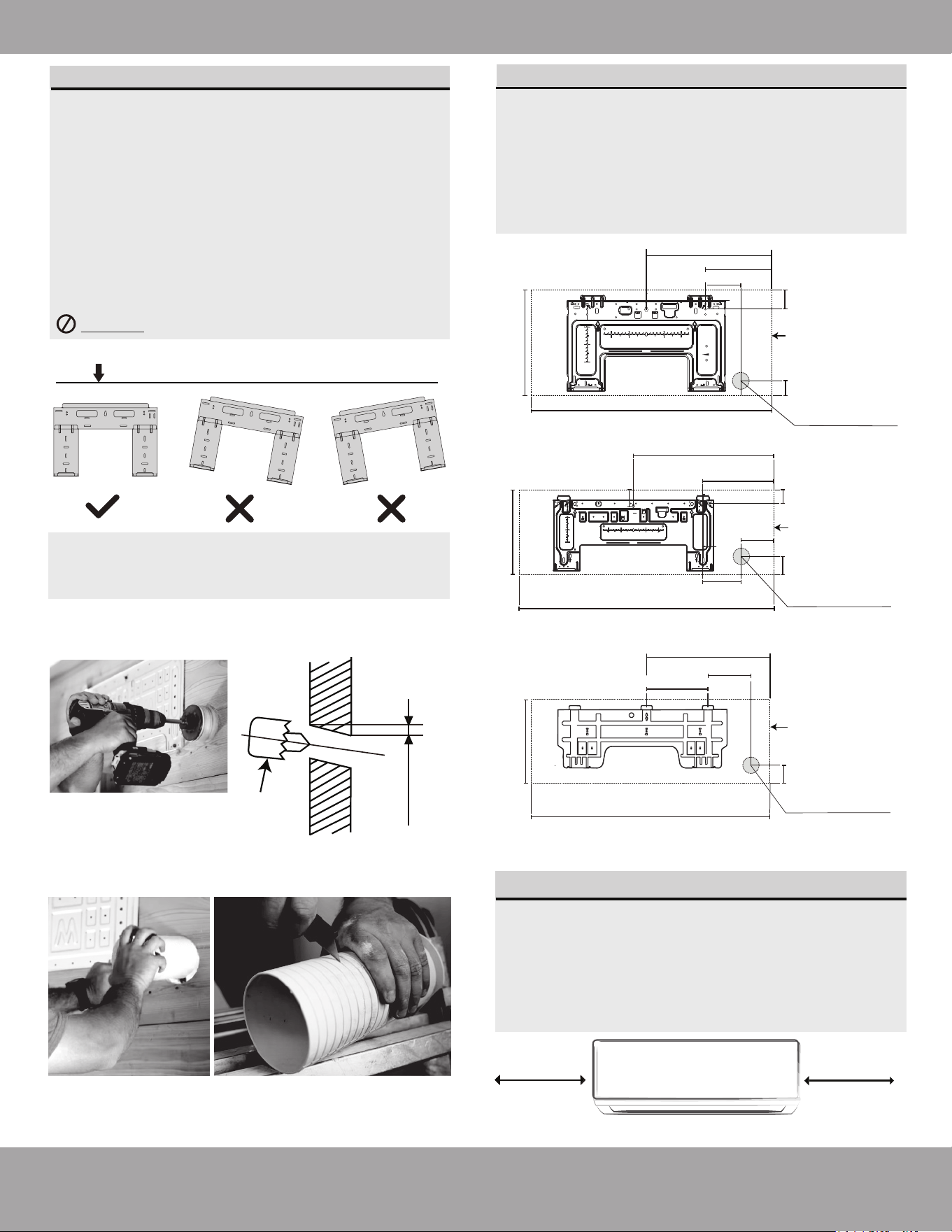
MOUNTING PLATE DIMENSIONS
Different models have different mounting
plates. In order to ensure that you have ample
room to mount the indoor unit, the diagrams
to the right show different types of mounting
plates along with the following dimensions:
• Height & Width of mounting plate
• Height & Width of indoor unit relative
to plate
• Recommended position of wall hole
• Relative distances between mounting holes
DO NOT attempt a left rear wall hole.
Correct orientation of Mounting Plate
NOTE REGARDING WALL STUDS
• Wall Mounting Bracket should be installed on
studs.
• Standard U.S. studs are 16 in (406.4 mm) on
center.
• Studs that are 16 in (406.4 mm) on center
correlates with the holes marked “US” on the
metal bracket.
NOTE: Use a level in order to ensure your
mounting plate is mounted to the wall
with the correct orientation shown above.
Correct Angle to Drill Wall Hole
Keep in mind that the hooks on the mounting
plate are smaller than the holes on the back of
the unit. If you find that there is not enough
room to connect embedded pipes to the indoor
unit, it can be adjusted left or right by 1.25-1.95
in (30-50 mm), depending on the model.
UNIT IS ADJUSTABLE
1.2-1.95
(30-50 mm)
1.2-1.95
(30-50 mm)
Adjustment range of indoor unit to the left or right
Wall
Indoor
Outdoor
Fig. 5.3
0.2 - 0.3 in
(5 - 7 mm)
Drill used to
create wall
hole
Wall Hole Sleeve Installation
Fig. 5.4
Outline of indoor unit
when mounted to plate
Fig. 5.5
22.8 in (578 mm)
11.7 in (298 mm)
13.2 in (335 mm)
Right rear wall
hole 3.5 in (90 mm)
42.5 in (1080 mm)
3.1 in (79 mm)
2.1 in (54 mm)
1.95 in (49 mm)
5.9 in
(149 mm)
5.9 in (149 mm)
9.01 in (229 mm)
15.78 in (401 mm)
4.96 in (126 mm)
1.65 in (42 mm)
11.69 in (297 mm)
Right rear wall
hole 3.5 in (90 mm)
31.57 in (802 mm)
2.28 in (58 mm)
14.25 in (362 mm)
Right rear wall
hole 3.5 in (90 mm)
49.55 in (1259 mm)
13.05 in (332 mm)
10.1 in (257 mm)
25.3 in (643.6 mm)
2.05 in (52 mm)
Outline of indoor unit
when mounted to plate
Outline of indoor unit
when mounted to plate
Series 36K Models
Series 18K & 24K Models
Series 9K & 12K Models
Page 23 mrcool.com
Indoor Unit Installation
CAUTION
Be extremely careful not to dent or damage the
piping while bending it away from the unit, as
this could negatively affect the performance.
Fig. 5.7
Step 4: Prepare indoor unit refrigerant piping
The piping of the indoor unit is attached to the back of
the unit towards the bottom. It will be covered with
insulation, and there will also be a drain pipe with
these. This piping will need to be bent and prepared
before it can be fed through the wall hole.
1.
2.
NOTE: Refrigerant piping should exit the indoor
unit from the right-hand side (Refer to Fig 5.6)
Based on the position of the wall hole, relative to
the mounting plate, determine the necessary angle
the piping will need to be bent to pass through the
wall hole when the unit is mounted to the bracket.
Grip the refrigerant piping at the base of the bend.
Then, slowly, and with even pressure, bend the
piping away from the back of the unit roughly 90
degrees. The piping should be sticking straight out
from behind the unit once completed (Refer to
Fig 4.6).
Step 5: Mount the Indoor Unit
In the following steps the indoor unit will now be
mounted to the wall bracket and the piping and
wires will be fed through the wall hole.
Double-check that the ends of the refrigerant
pipes are sealed (screw on caps are still in place)
to prevent any dirt or foreign material from
entering the pipes.
Feed the MC Cable/signal wire (should be
protected by conduit) through the wall hole.
Carefully lift the indoor air handler, and slowly
feed the taped bundle of refrigerant pipes and
drain hose through the wall hole, as you
position it to mount to the wall bracket.
1.
2.
3.
3.
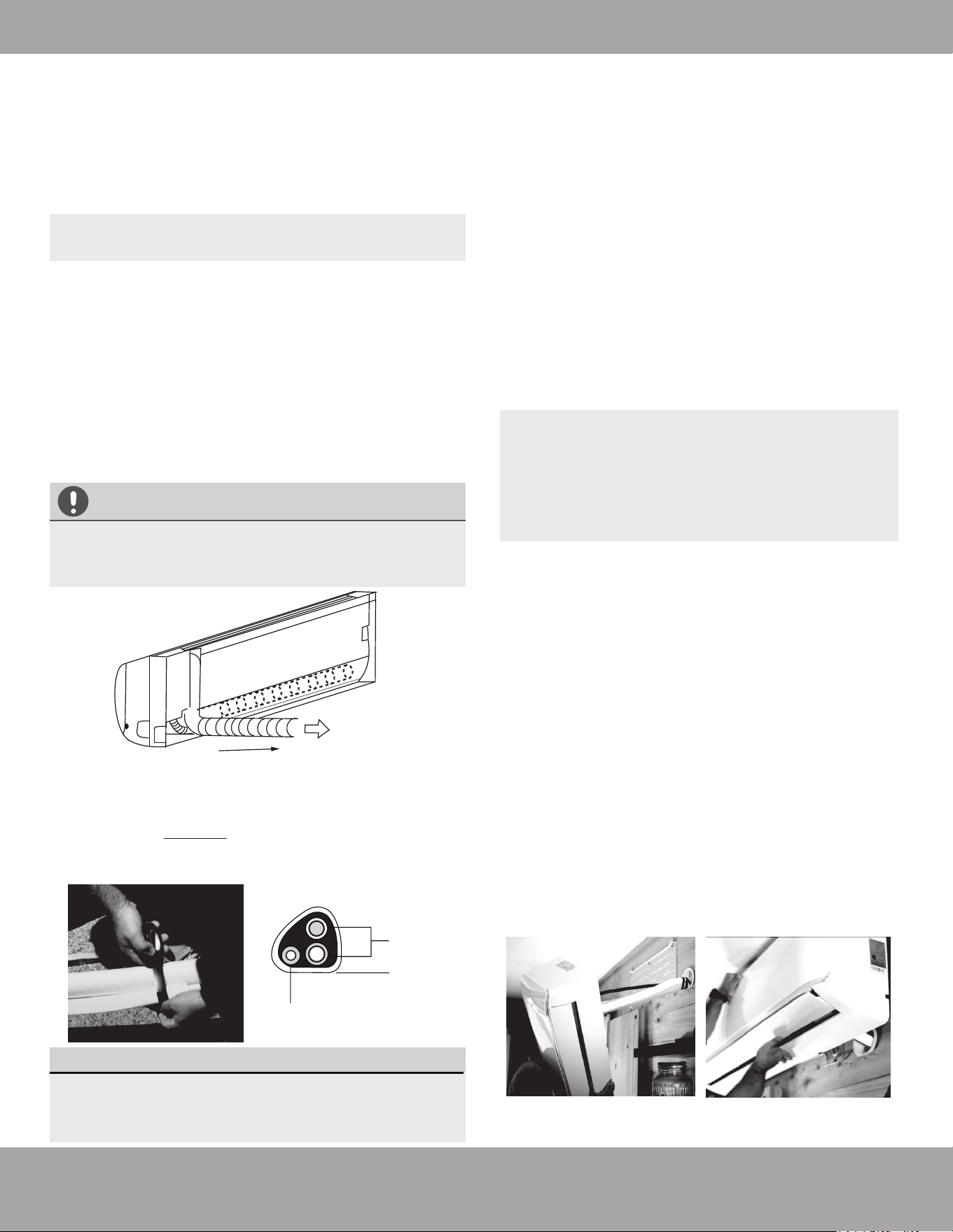
Now, you will need to lightly tape the refrigerant
piping and drain pipe together in a bundle, using
electrical tape, making sure that the drain pipe is at
the bottom. DO NOT tape the ends of the piping
(connectors). Refer to Fig 5.7 and the image below
for the correct orientation of the piping when taping.
Refrigerant
piping
Drain hose
Tape
Fig. 5.6
The drain hose must be placed at the bottom of
the bundle. If it is not, it could cause the drain
pan to overflow, which could lead to fire or water
damage.
DRAIN HOSE MUST BE ON BOTTOM
NOTE: Positioning the air handler on to the
wall bracket, while feeding the piping
through the wall hole, might be difficult for a
single person to manage. If so, it may be
necessary to seek the assistance of another
person for this step.
Slightly lean the top of the air handler toward the
wall and hook the top of the indoor unit on the
upper hook of the wall mounting plate.
Check that the unit is hooked firmly on the
mounting plate by applying slight pressure to the
left and right-hand sides of the unit. The unit
should not jiggle or shift.
Using even pressure, push down on the bottom
half of the unit. Continue pushing down until the
unit snaps onto the hooks along the bottom of
the mounting plate.
Again, check that the unit is firmly mounted to
the wall bracket by applying slight pressure to
the left and right-hand sides of the unit.
4.
5.
6.
7.
Repeat these steps for each of the additional air
handler you are installing.
8.
Page 24mrcool.com
Indoor Unit Installation
Installation Instructions –
Outdoor Unit
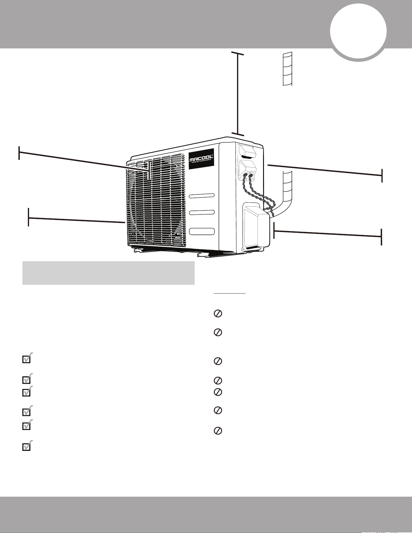
Step 1: Selecting an Installation Location
Before installing the outdoor unit, you must
choose an appropriate location. Use the following
guidelines to help you select an appropriate
location.
Proper installation locations should meet
following guidelines:
Meets all spatial requirements shown in
in the illustration above (Fig. 6.1)
Good air circulation and ventilation
Firm and solid location that can support
the unit and will not cause vibration
Noise from the unit will not disturb others
Protected from prolonged periods of
exposure to direct sunlight or rain
If installed in an area where snowfall is
expected, take appropriate measures to
prevent ice buildup and coil damage.
Mount the unit high enough to be above
the average accumulated area snowfall.
The minimum height must be 18 inches.
DO NOT install unit in the following
locations:
Near an obstacle that will block air inlets
and outlets.
Near a public street, crowded areas, or
where noise from the unit will disturb
others.
Near animals or plants that could be
harmed by hot air discharge.
Near any source of combustible gas.
In a location that is exposed to large
amounts of dust.
In a location exposed to excessive
amounts of salty air.
In a location that exposes the unit to
large amounts of forced water.
Fig. 6.1
6
Outdoor Unit Installation
Minimum Clearance
above unit:
24 in (60 cm)
Minimum Clearance
on the left side of
unit: 12 in (30 cm)
Minimum Clearance
on the right side of
the unit: 24 in (60 cm)
Minimum Clearance
in front of the unit:
79 in (200 cm)
Minimum Clearance
between the back of
the unit and wall:
**Ground Installed:
12 in (30 cm)
**Bracket Installed:
6 in (15 cm)
NOTE: Install the unit by following local codes and
regulations, these may slightly differ between
regions.
Page 25 mrcool.com
Outdoor Unit Installation
SPECIAL CONSIDERATIONS FOR
EXTREME WEATHER
If the unit is exposed to heavy wind:
Install the unit so the air outlet fan is at a
90° angle to the direction of the wind. If
needed, build a barrier in front of the unit
to protect it from extremely heavy winds.
Ensure the wind barrier does not block
necessary airflow. See Fig. 6.2 and Fig. 6.3
below.
If the unit is frequently exposed to heavy
rain or snow: Build a shelter above the unit
to protect it from the rain or snow. Be
careful not to obstruct airflow around the
unit.
If the unit is frequently exposed to salty air
(seaside): Use an outdoor unit that is
specially designed to resist corrosion.
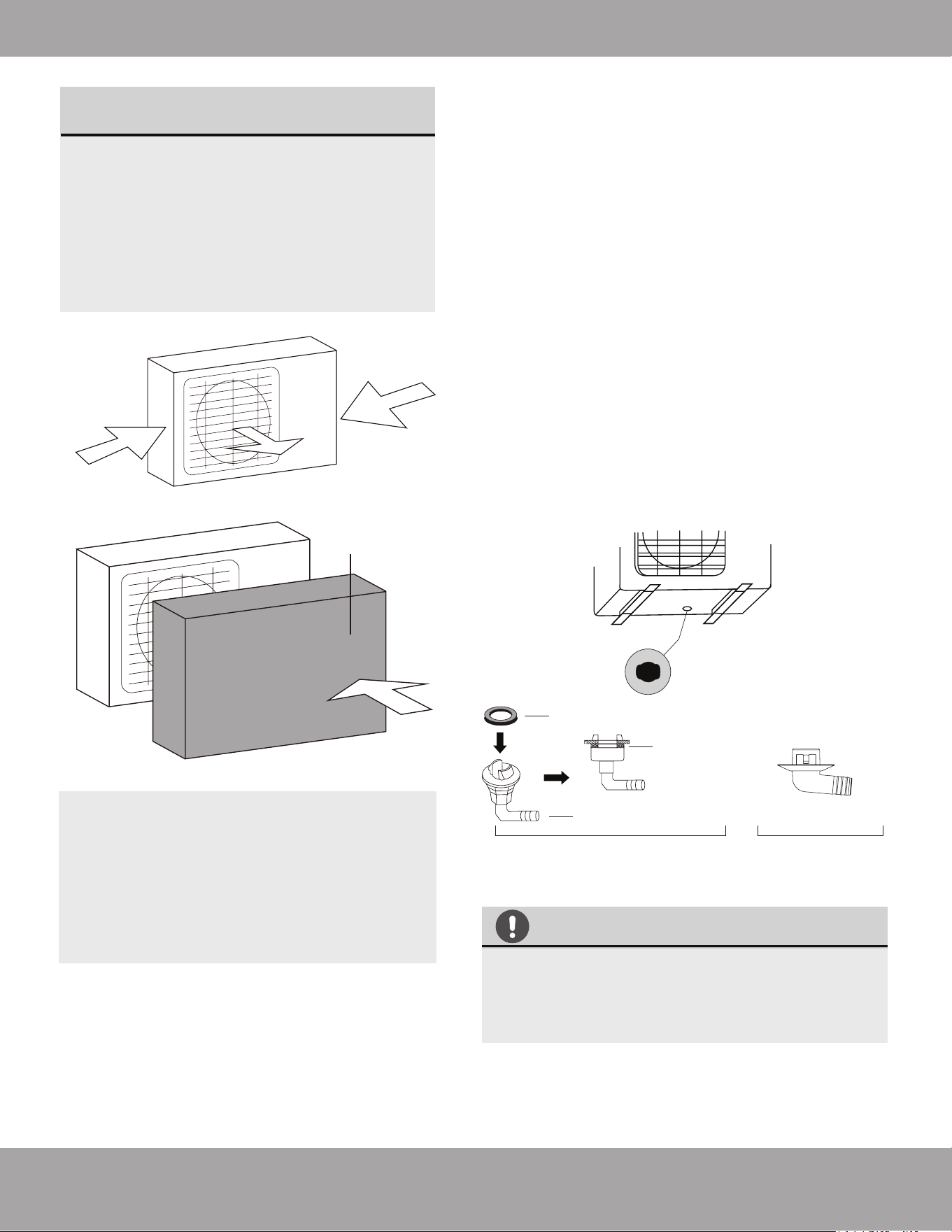
Step 2: Install drain joint
Strong wind
Strong wind
Fig. 6.2
Fig. 6.3
Strong wind
DRAINAGE IN COLD CLIMATES
In cold climates, make sure that the drain hose
is as vertical as possible to ensure swift water
drainage. If water drains too slowly, it can
freeze.
Seal
Drain joint (only use if elevated)
(A) (B)
Base pan hole of
outdoor unit
Seal
Fig. 6.4
If the drain joint comes with a rubber seal (see
Fig. 6.4 - A), do the following:
1. Fit the rubber seal on the end of the drain joint
that will connect to the outdoor unit.
2. Insert the drain joint into the hole in the base pan
of the unit.
3. Rotate the drain joint 90° until it clicks in place
facing the front of the unit.
4. Connect a drain hose extension (not included) to
the drain joint to redirect water from the unit during
heating mode.
If the drain joint does not come with a rubber seal
(see Fig. 6.4 - B), do the following:
1. Insert the drain joint into the hole in the base pan of
the unit. The drain joint will click in place.
2. Connect a drain hose extension (not included) to the
drain joint to redirect water from the unit during
heating mode
Wind Baffle
Heat pump units require a drain joint if the unit
is elevated. Before bolting the outdoor unit in
place, you must install the drain joint at the
bottom of the unit. NOTE: there are two
different types of drain joints depending on
the type of outdoor unit.
Page 26mrcool.com
Outdoor Unit Installation
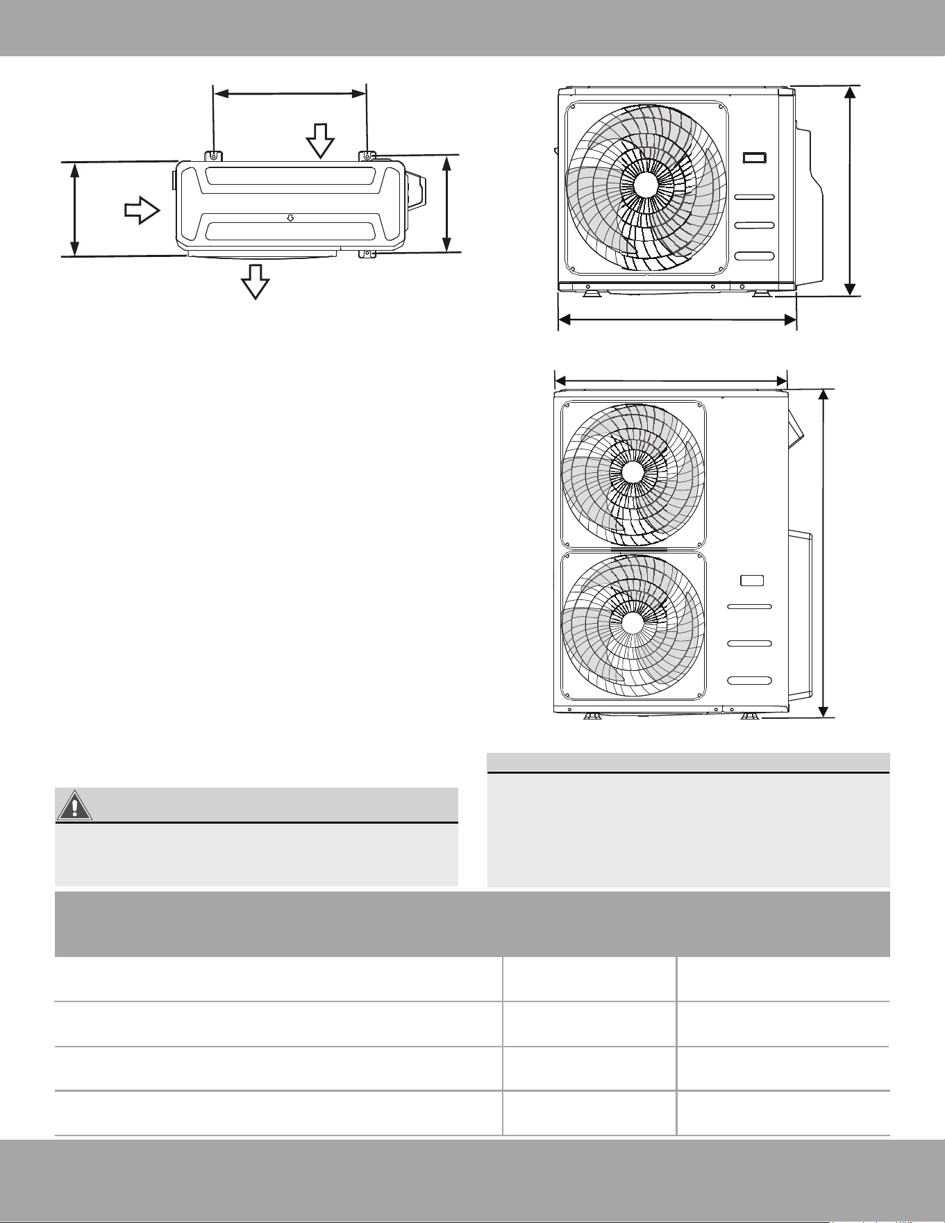
UNIT MOUNTING DIMENSIONS
The following is a list of different outdoor unit sizes
and the distance between their mounting feet.
Prepare the installation base of the unit according
to the dimensions in the table below, using the
illustrations of the unit above (Fig 6.5) as a guide to
correspond with the table.
Step 3: Anchor Outdoor Unit
The outdoor unit can be anchored to the ground or
to a wall-mounted bracket using M-10 bolts. Prepare
the installation base of the unit according to the
dimensions below. For instructions of how to mount
the unit to a wall mounted bracket, please refer to the
following page.
If you are installing the outdoor unit on the
ground, or a concrete mounting platform, use
the following steps:
1. Mark the positions for four expansion bolts based
on dimensions in the Mounting Dimensions
chart and illustrations above.
2. Pre-drill holes for expansion bolts.
3. Clean concrete dust away from the holes.
4. Place a nut on the end of each expansion bolt.
5. Hammer expansion bolts into the pre-drilled holes.
6. Remove the nuts from the expansion bolts, and
place outdoor unit on bolts.
7. Put a washer on each of the expansion bolts, then
reinstall the nuts.
8. Using a wrench, tighten each nut until snug.
Outdoor Unit Dimensions:
Inches (Millimeters)
Width (W) x Height (H) x Depth (D)
Mounting Dimensions:
Inches (Millimeters)
Width (A)
Depth (B)
37.24 in x 31.89 in x 16.14 in
(946 mm x 810 mm x 410 mm)
26.50 in
(673 mm)
DIY-MULTI3-27HP230C
DIY-MULTI4-36HP230C
37.24 in x 31.89 in x 16.14 in
(946 mm x 810 mm x 410 mm)
26.50 in
(673 mm)
15.87 in
(403 mm)
35.04 in x 26.50 in x 13.46 in
(890 mm x 673 mm x 342 mm)
26.10 in
(663 mm)
DIY-MULTI2-18HP230C
13.93 in
(354 mm)
15.87 in
(403 mm)
DIY-MULTI5-48HP230C
37.48 in x 52.48 in x 16.34 in
(952 mm x 1333 mm x 415 mm)
24.96 in
(634 mm)
15.90 in
(404 mm)
W
W
H
D
Air Inlet
A
B
Air Outlet
Air Inlet
Fig. 6.5
TOP VIEW
FRONT VIEW
H
18K, 27K, & 36K
48K
WHEN DRILLING INTO CONCRETE, EYE
PROTECTION IS RECOMMENDED AT ALL
TIMES.
WARNING
mrcool.com
Outdoor Unit Installation
If you are installing the unit on a wall-mounted
bracket, follow these steps:
TO REDUCE VIBRATION OF WALL-MOUNTED UNIT
Before installing a wall-mounted unit, make sure
that the wall is made of solid brick, concrete, or
a similarly strong material. The wall must be able
to support at least 4 times the weight of the unit.
If allowed, you can install the wall-mounted unit
with rubber gaskets to reduce vibration and noise.
1. Mark the position of the bracket holes based on
the dimensions in the Mounting Dimensions chart
on the previous page.
2. Pre-drill the holes for the expansion bolts.
3. Clean dust and debris away from the holes.
4. Place a washer and nut on the end of each
expansion bolt.
5. Thread expansion bolts through the holes in the
mounting brackets. Then, put the mounting
brackets in position and hammer the expansion
bolts into the wall.
6. Check that the mounting brackets are level.
7. If the feet of the outdoor unit have rubber pads
already installed, and you’re using a MRCOOL
®
wall-mounted bracket, remove them before
attempting to mount the condenser to the bracket.
The mounting bracket has rubber isolating pads on
it that will take the place of these.
Page 27
Indoor Air Handler Compatibility with Multi-Zone Condensers
Connective Pipe Size for Indoor Air Handlers
OUTDOOR CONDENSER | DIY-MULTI2-18HP230C
DIY-09-HP-WMAH-230C DIY-12-HP-WMAH-230C
OUTDOOR CONDENSER | DIY-MULTI3-27HP230C
DIY-09-HP-WMAH-230C
DIY-12-HP-WMAH-230C
DIY-18-HP-WMAH-230C25
OUTDOOR CONDENSER | DIY-MULTI4-36HP230C
DIY-09-HP-WMAH-230C
DIY-12-HP-WMAH-230C
DIY-18-HP-WMAH-230C25
DIY-24-HP-WMAH-230C25
(Only 1 per Condenser)
LIQUID PIPE
Inches
INDOOR UNIT CAPACITY (Btu/h)
GAS PIPE
Inches
9K/12K/18K
24K/36K
1/4 in
3/8 in
1/2 in
5/8 in
OUTDOOR CONDENSER | DIY-MULTI5-48HP230C
DIY-09-HP-WMAH-230C
DIY-12-HP-WMAH-230C
DIY-18-HP-WMAH-230C25
DIY-24-HP-WMAH-230C25
DIY-36-HP-WMAH-230C25
(Only 1 per Condenser)
8. Carefully lift the unit and place its mounting feet
on the brackets.
9. Then, bolt the unit firmly to the brackets.
mrcool.com Page 28
Refrigerant Piping Connection
Step 1: Prepare exterior wall hole
Before the refrigerant piping can be installed and
connected to the indoor and outdoor units, some
additional steps are required to prepare the exterior.
1. Install finishing ring/cap to the exterior portion of
the wall hole.
2. Place your hand on the underside of the piping
coming through the exterior wall hole (from indoor
unit), close to the wall. With your other hand, using
even pressure, carefully bend the piping downward
toward the wall, being mindful not to damage or
dent the piping in the process.
3. Pack the wall hole with the supplied Neoprene (or
Spray Foam can be used) to seal the hole, filling any
space that was not taken up by the refrigerant
piping and lines.
CAUTION
Be extremely careful not to dent or damage the
piping while bending it down the exterior wall,
as this could negatively affect the performance.
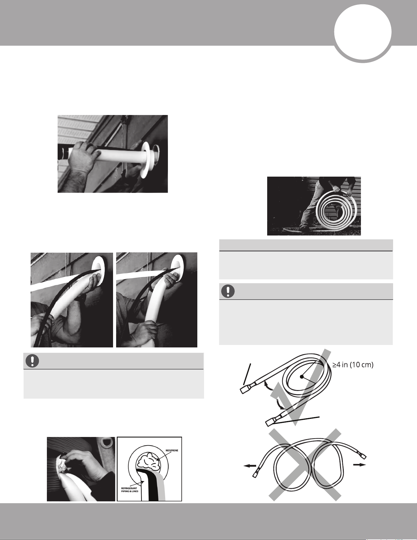
Step 2: Unwind Quick Connect® Line Set to
necessary length
Carefully unroll to indoor
handler connection
Connect directly to
exterior condensor
Keep excess coiled
Radius
1. Use your hands to slowly unwind the copper
piping of one end of the Quick Connect® Line Set.
The end you unwind will connect to the indoor
unit piping. You should unwind the end until the
connectors are close to flat on the ground (with
little to no bend). If this is not done, it could make
the line set difficult to maneuver when aligning
the connectors with the air handler piping. Only
unwind as much as necessary for your application,
and allow any excess to remain coiled (Refer to
Fig. 7.1).
If the pipe is repeatedly bent or extended, it
will become hard and difficult to manipulate.
Avoid bending or extending the pipe more than
3 times, or at an angle greater than 90°, as it
could break.
CAUTION
When bending connective refrigerant piping, it
needs to have a minimum bend radius of 4
inches (Refer to Fig 7.1).
MINIMUM BEND RADIUS
Fig. 7.1
7
Page 29 mrcool.com
Step 3: Connect Line Set to Indoor Unit Refrigerant Pipe Connectors (both ends):
IMPORTANT:
IMPORTANT:
Before you continue, it is essential that you read
the following instructions fully and carefully.
3.2 IMPORTANT INFORMATION
PLEASE READ FULLY BEFORE PROCEEDING TO NEXT STEP
}
.
.
.
.
.
The line sets are designed to only be installed once.
The seal within the line set cannot be guaranteed if
they are installed more than once. This will void the
warranty. They also contain a compression fitting to
seal and do not require a thread sealant (Teflon
tape, etc.). Using a sealant may actually cause the
connection to leak over time.
• Follow the detailed instructions for connecting the
line set to the indoor unit and outdoor units. We can
only provide a warranty if the line set is installed
correctly as described in the instructions.
• To prevent leaks, ensure that the Quick Connect
®
connectors are free of dirt. Moisture or foreign
bodies will adversely affect the function of the
connectors and could lead to a risk of refrigerant
loss (not covered by the warranty).
• Only install the line set outdoors in dry weather.
• The line set must not be plastered over after being
installed.
• Always wear work gloves and goggles and use
caution when handling refrigerant. Please make
sure that refrigerant is never allowed to enter the
environment. Improper handling of refrigerant may
be harmful to your health.
• The equipment must never be operated without the
line set connected, otherwise the equipment will be
damaged immediately.
• Quick Connect
®
line set connections must only be
tightened using the appropriate open-ended or
crescent (adjustable-type) wrenches.
DO NOT remove the sealing caps and stoppers
from the line set or valves until immediately
before they are to be connected.
DO NOT smoke during the installation.
3.3 Connecting the Quick Connect
®
Line Set to
the piping from indoor unit
1. Do not remove the plastic seals of the piping coming
from the indoor unit, or the appropriate line set
connector, until immediately before they are to be
connected. The plastic seals on each of the
connectors should be color-coded to match the
seals of the corresponding pipes they are to be
connected to.
2. Align the refrigerant pipes correctly, making sure the
dimensions of the connecting refrigerant pipe
match. Unscrew the seals and place the screw
connector of the line set just onto the threads of the
piping from the indoor unit and tighten the first few
threads by hands.
Refrigerant Piping Connection
NOTE: Depending on the capacity rating of your unit,
(12K, 18K, 24K, 36K) the wrench sizes needed will
vary, refer to the table below (the unit uses metric
sizes, the standard sizes listed are approximations).
Based on the availability of wrenches in some of the
sizes needed, the recommended method is to use
crescent wrenches that can be adjusted to fit the size
each step requires.
3.1 Tools needed
Opened-ended wrench sizes needed
(1x of each of these)
12K & 18K 24K & 36K
3/4” / 19 mm 3/4“ / 19 mm
7/8” / 22 mm 15/16“ / 24 mm
15/16” / 24 mm 1“ / 26 mm
1” / 26 mm 1-1/8” / 29 mm
1-1/4” / 31 mm
1x HVAC Torque Wrench (if available)
1x Allen key, 5 mm
1x Phillips-head screwdriver
1x leak-detection spray or a soapy water solution
(liquid detergent/mix, applied by brush or spray bottle)
Or 2x Crescent
(adjustable-type)
Wrenches
If the screw connections are tightened with too little
torque, they will leak. If they are tightened with too
much torque, the screw connections could suffer
damage. Please refer to the torque requirements
section for more information. If you do not feel
confident connecting the line set connectors yourself,
it is imperative that you contact the MRCOOL
®
customer service team or an HVAC professional.
Pat. https://mrcool.com/mrcool-patents/
Page 30mrcool.com
Refrigerant Piping Connection
TORQUE REQUIREMENTS
1. Excessive force can break the connector or damage the refrigerant piping. You must not exceed the
torque requirements shown in the table below.
2. You can find the Outer Pipe Diameter stamped (in inches) on the valve set of the condenser. Refer to
this when finding and applying the torque values in the table below.
3. Please note that there may be differences in Torque Wrenches (i.e. automotive torque wrench versus
an HVAC torque wrench) and that a socket style wrench cannot be used in this installation.
NOTE: Torque ratings in the table below are to be used if you have access to an HVAC torque wrench.
These are available for purchase from online retailers. However, it is possible to complete installation
of refrigerant line sets with conventional open-ended/crescent wrenches. It is imperative, however,
that you not overtighten the connector, and that once the lines have been fully connected, you follow
the steps to check for leaks. If you do not feel comfortable attempting this, please contact a qualified
HVAC technician.
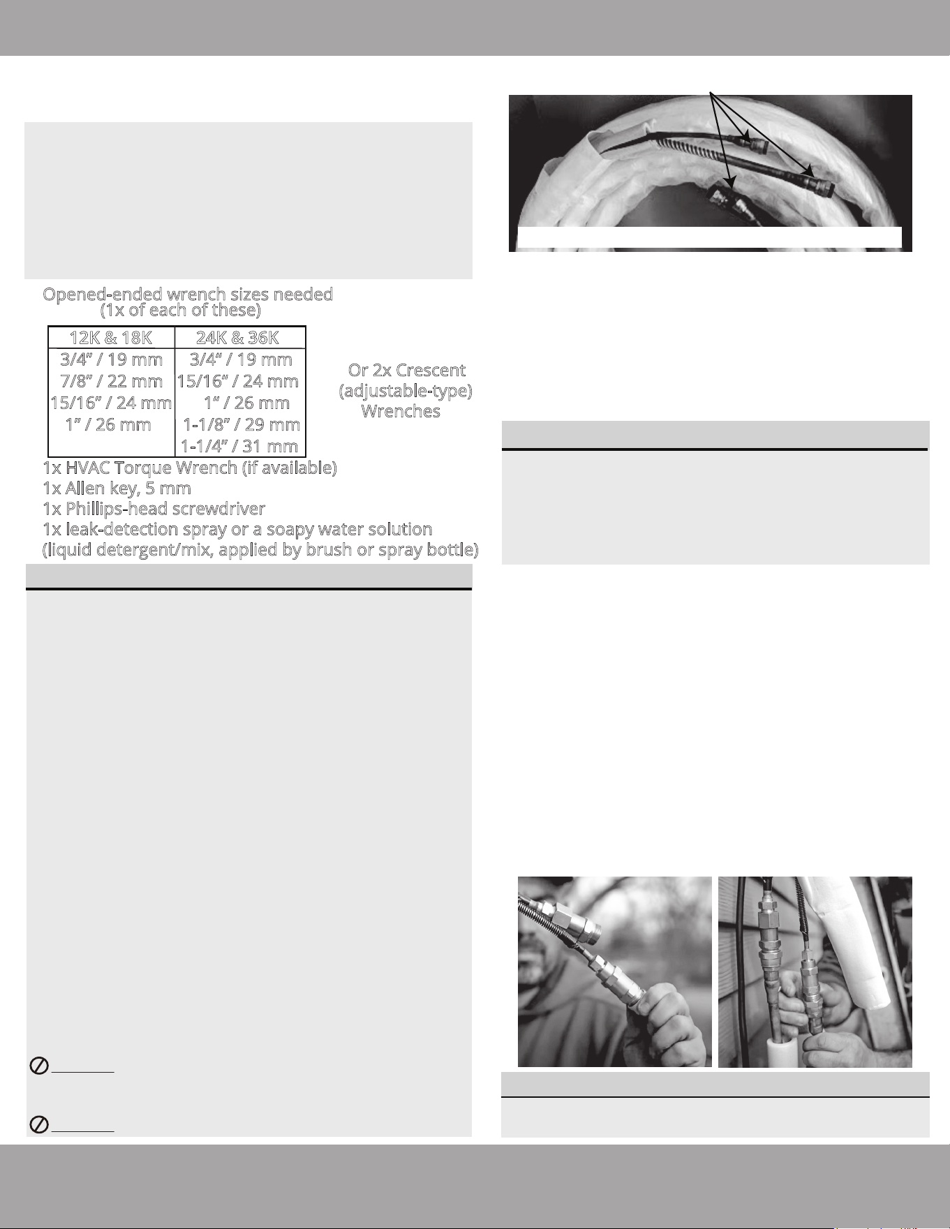
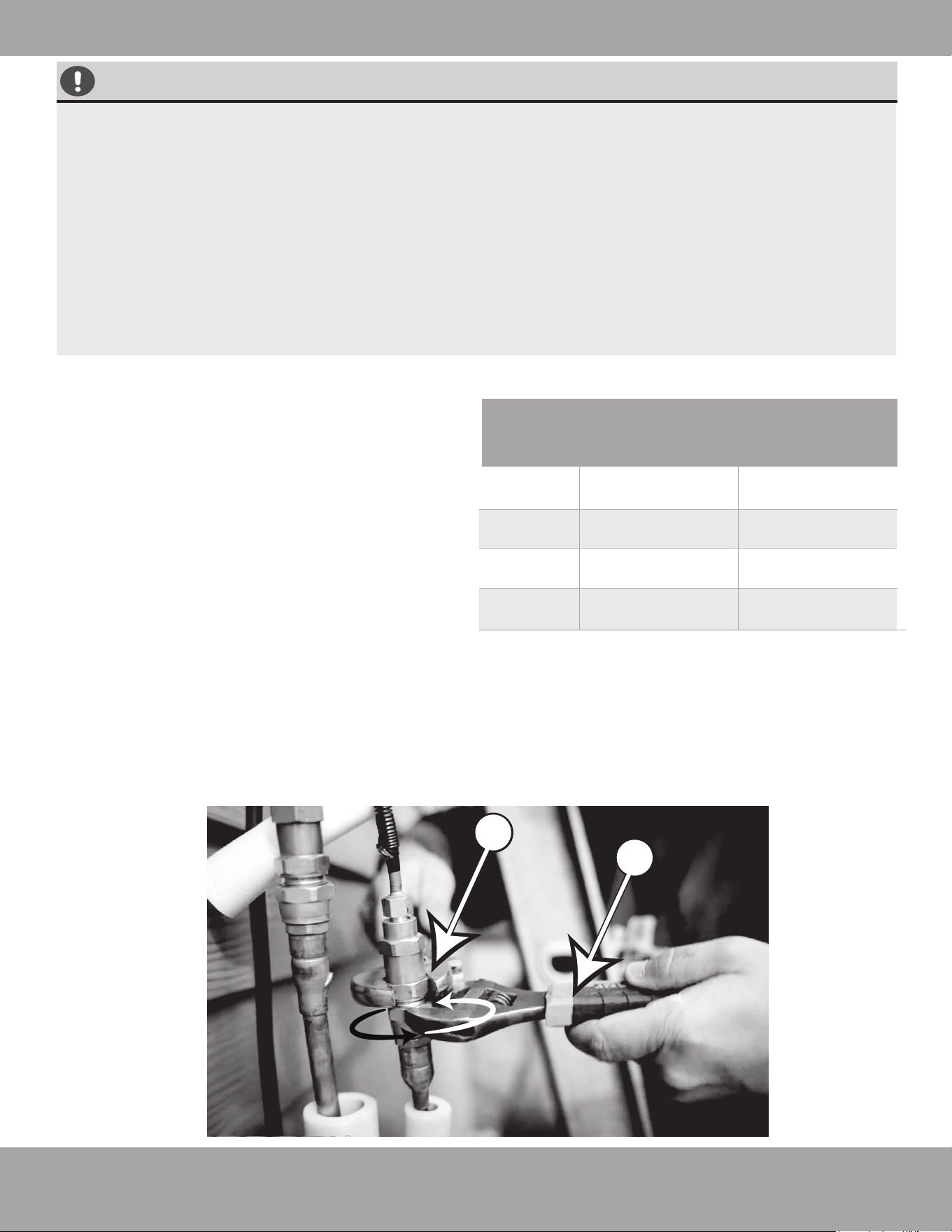
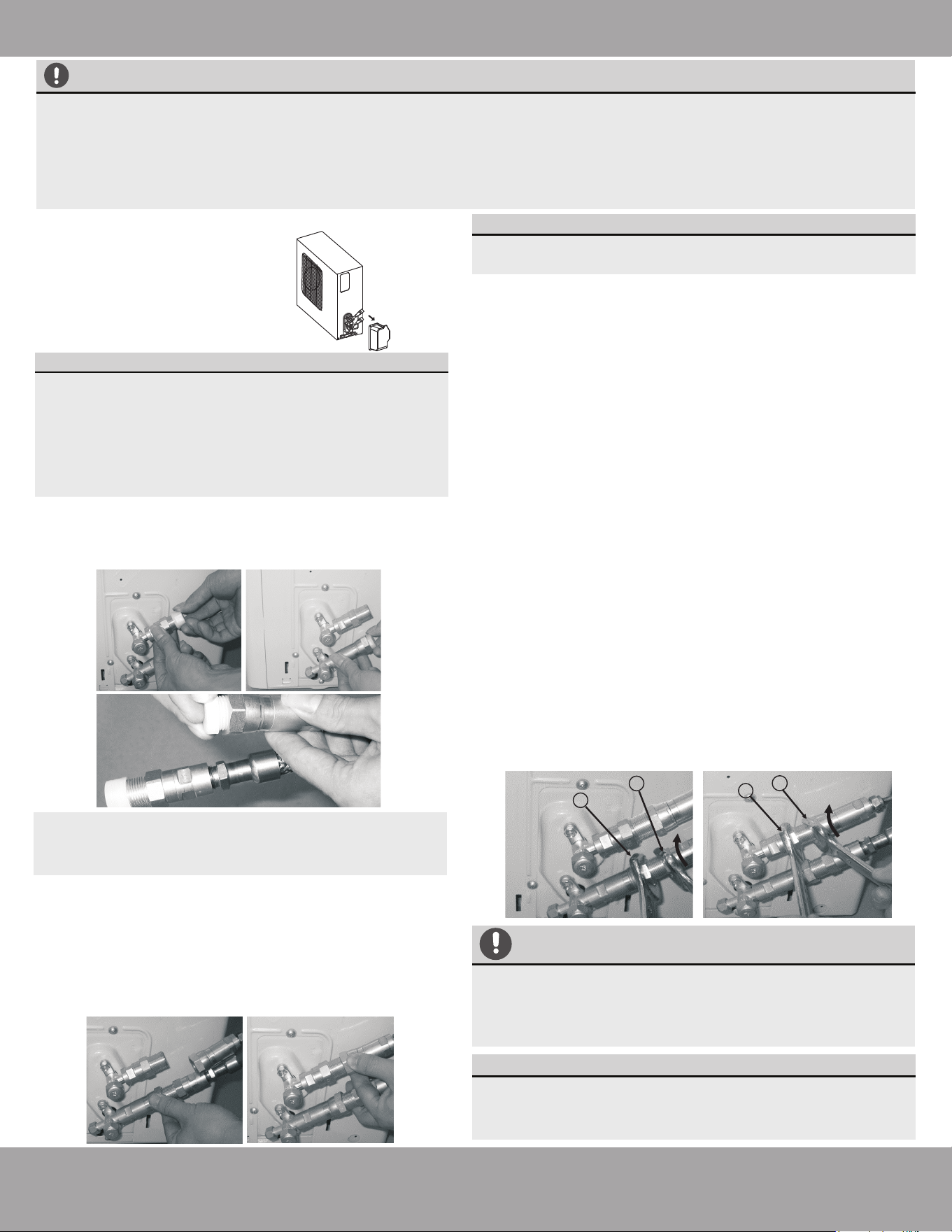
3. Using the image below as a guide, and the steps
outlined in this paragraph, you will now tighten the
nuts of the screw connectors of the Quick
Connect
®
line set to the indoor unit. Using two
appropriate sized open-ended wrenches
(depending on the dimensions of the connector)
or adjustable crescent wrenches, place one of the
wrenches on the nut marked “1”, and the other
wrench on the nut marked “2,” as shown in the
image below. Now, turn the wrench marked “2” in
the direction of the rotational arrows, as shown,
while holding the other wrench in place. Continue
to tighten the connector until snug. NOTE: work
quickly and make sure the screw connectors
do not become crooked as you tighten them.
* If an HVAC torque wrench is available: Once
the connector is snug, using the torque wrench,
tighten the connector to the specified torque
rating, as listed in the table to the right (based on
pipe/coupling size).
* If an HVAC torque wrench is NOT available:
Using two wrenches you used to tighten the
connector, once the connector is snug, turn the
wrench slightly beyond that point to torque the
connector,but do not overtighten it.
4. Repeat the same process for the second line.
1
2
FA06
FA09
FA12
FA16
3/8 in (9.5 mm)
1/2 in (12.7 mm)
3/4 in (19.1 mm)
1 in (25.4 mm)
18-20 lb/ft
(24.4-27.1 Nm)
30-35 lb/ft
(40.6-47.4 Nm)
45-50 lb/ft
(61.0-67.7 Nm)
60-65 lb/ft
(81.3-88.1 Nm)
Stamp
(on
connector)
Coupling
Size
inch (millimeter)
Tightening
Torque
lb-ft (N-m)
Page 31 mrcool.com
Refrigerant Piping Connection
NOTE
IMPORTANT
1
1
2
2
The coupling of the outdoor unit uses tapping rings,
if you disconnect and reconnect the refrigerant
pipes, it could cause it to leak. This will also void the
warranty.
Step 4: Connect Line Set to the Outdoor Unit
IMPORTANT:
Before you continue, it is essential that you read
the following instructions carefully.
NOTE:
Keep excess refrigerant hose coiled. Wrap with
protective tape and store behind the condenser in a
horizontal position (flat with the ground).
IMPORTANT:
If you are using a 24K or greater capacity air
handler with a 4-zone or 5-zone condenser, a line
set adapter kit (included) needs to be installed on
the outdoor unit before the next steps can be
completed. Please refer to the Installation Steps
for Line Set Adapter Kit section on the next page
and complete before continuing.
2. Do not remove the plastic seals from the outdoor
unit piping connectors and corresponding
refrigerant pipes (line set to be attached) until
immediately before you connect them.
NOTE: Ensure the adapters attached to the
outdoor valves have been tightened properly
before attempting to connect the line set.
3. Align the refrigerant pipes so they line up with the
corresponding valves and have enough slack.
NOTE: The refrigerant pipes must be
connected to the valves with as little stress as
possible. Unscrew the plastic seals and place the
screw connector of the refrigerant line just onto
the threads of the outdoor unit, tightening the first
few threads by hand.
1. First remove the water
tray on the outdoor
unit as shown in the
illustration to the right.
4. Using the first image below as a guide, starting with
the bottom screw connector, you will now tighten the
line set to the outdoor unit. Using two appropriate
sized open-ended wrenches (depending on the
dimensions of the connector), or adjustable crescent
wrenches, place one of the wrenches on the nut
marked “1”, and the other wrench on the nut marked
“2,” Now, turn the wrench on nut “2” in the direction of
the rotational arrow, while holding the other wrench in
place, as seen in the first image below. Continue to
tighten the connector until snug. NOTE: work quickly
and make sure the screw connectors do not
become crooked as you tighten them.
*If an HVAC torque wrench is available: Once the
connector is snug, using the torque wrench, tighten
the connector to the specified torque rating, listed in
the table on the next page (based on the
pipe/coupling size).
*If an HVAC torque wrench is NOT available:
Using the two wrenches you used to tighten the
connector, once the connector is snug, then turn the
wrench slightly beyond that point to torque the
connector, but do not overtighten it.
5. Repeat the same process for the top screw connector,
using the second image below as a guide. Then, repeat
all of these steps for every line set for all of the other
air handlers.
The connection ports on the outdoor condenser are labeled A,B,C,D,E, etc. The capacities of the air
handlers you use will determine which ports they should be connected to. The largest capacity air
handler should be connected to the “A” port. Then, the next largest capacity air handler should be
connected to the “B” port and so on. To distinguish the connectors to be connected to the indoor units
and outdoor unit, the refrigerant pipe connectors have been labelled “A”, “B”, “C”, “D”, and “E”. Ensure
the marks on the connectors match the indoor units and outdoor unit respectively during connection.
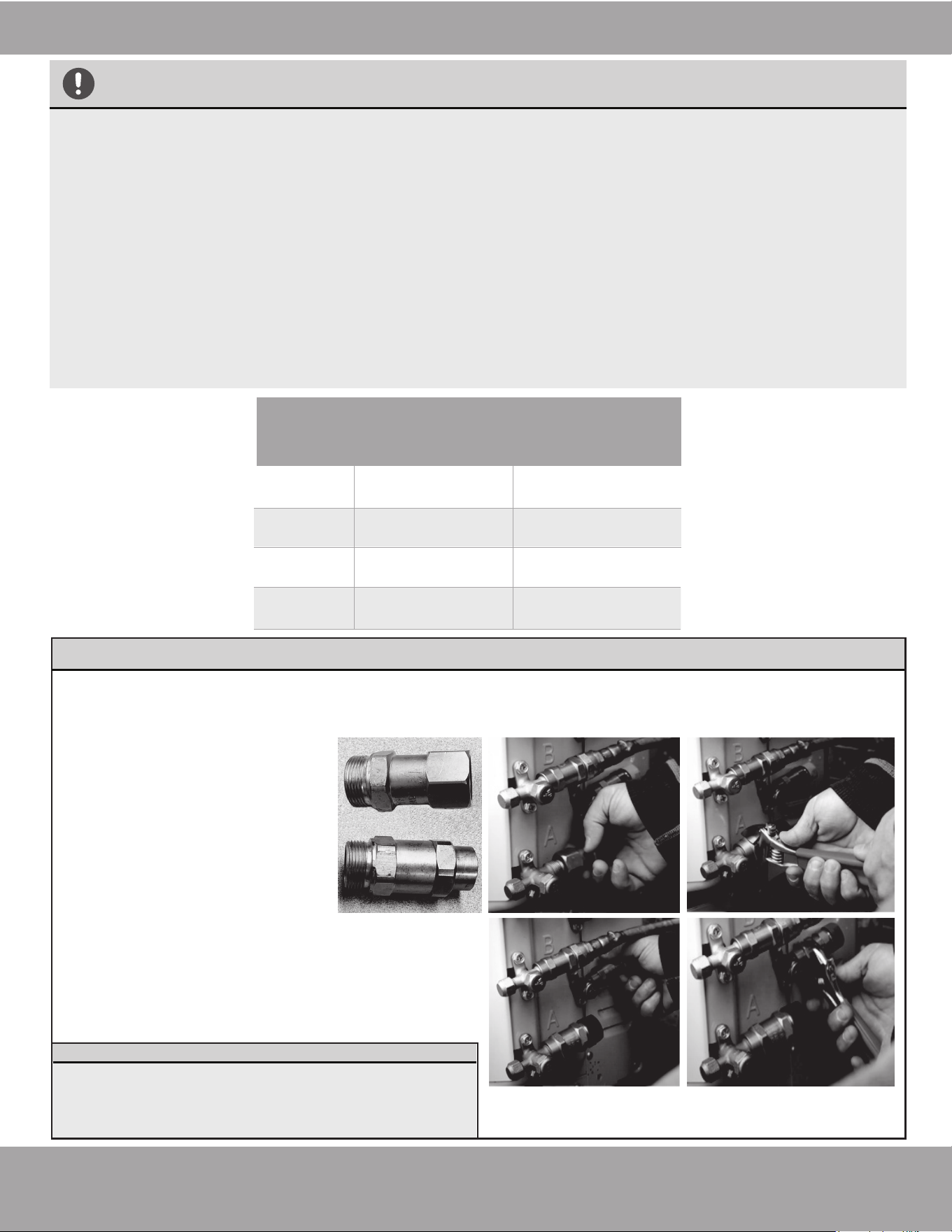
Page 32mrcool.com
Refrigerant Piping Connection
1. Excessive force can break the connector or damage the refrigerant piping. You must not exceed the
torque requirements shown in the table below.
2. You can find the Outer Pipe Diameter stamped (in inches) on the valve set of the condenser. Refer to
this when finding and applying the torque values in the table below.
3. Please note that there may be differences in Torque Wrenches (i.e. automotive torque wrench versus
an HVAC torque wrench) and that a socket style wrench cannot be used in this installation.
NOTE: Torque ratings in the table below are to be used if you have access to an HVAC torque
wrench. These are available for purchase from online retailers. However, it is possible to
complete installation of refrigerant line sets with conventional open-ended/crescent wrenches. It
is imperative, however, that you not over-tighten the connector, and that once the lines have
been fully connected, you follow the steps to check the pipe connections for leaks (Refer to the
Electrical & Gas Leak Checks section of this manual for more information). If you do not feel
comfortable attempting this, please contact a qualified HVAC technician.
TORQUE REQUIREMENTS
FA06
FA09
FA12
FA16
3/8 in (9.5 mm)
1/2 in (12.7 mm)
3/4 in (19.1 mm)
1 in (25.4 mm)
18-20 lb/ft
(24.4-27.1 Nm)
30-35 lb/ft
(40.6-47.4 Nm)
45-50 lb/ft
(61.0-67.7 Nm)
60-65 lb/ft
(81.3-88.1 Nm)
Stamp
(on
connector)
Coupling Size
inch (millimeter)
Tightening Torque
lb-ft (N-m)
If you are using a 24K or greater capacity Air Handler with a 4-zone or 5 -zone condenser, you will need to
install the included line set adapter kit to the outside unit, before the line set can be connected. This requires
you to replace both of the connected couplings that are on port A of the outside unit, so the air handler can be
connected.
Installation Steps for Line Set Adapter Kit (for use with 24K or greater capacity Air Handler)
1. Unscrew the couplings from both
connectors of port A of the
outside unit by hand.
2. Screw each of the provided
couplings, from the line set
adapter kit, to the appropriate
connector of the outside unit by
hand.
3. Now, using an open-ended
wrench, or a crescent (adjustable-style) wrench,
tighten both of the couplings securely.
4. Once completed, revert back to Step 4: Connect
Line Set to the Outdoor Unit and continue the
installation.
IMPORTANT:
Later in the installation process you will be
asked to check for leaks at the piping
connections. Be sure to include checking these
adapters at both ends during your check.
Line Set Adapter Kit
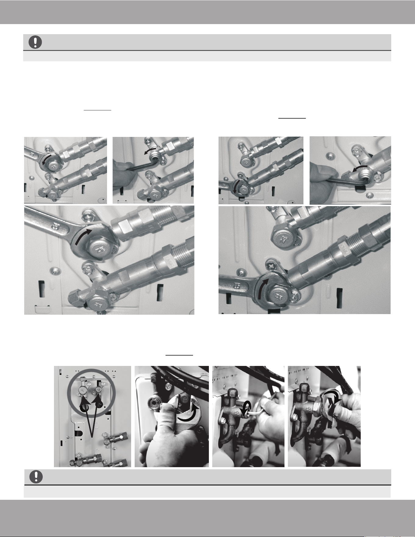
Page 33 mrcool.com
Refrigerant Piping Connection
Step 5: Opening the refrigerant valves of the outdoor unit
3. If you’re installing a 3, 4, or 5-zone condenser, after opening all of the line set connection valves, you must
also open the two main valves (King Valves), as shown in the images below. To do this, first unscrew the
caps from the valves in a counter-clockwise direction using an appropriate-sized wrench, or crescent
(adjustable-type) wrench. Then, insert a 5 mm Allen key and open each of the valves by turning them
counter-clockwise as far as they will go. DO NOT force it. Then, reinstall the caps and tighten them
securely to ensure that they are properly sealed.
King
Valves
If the King Valves are not fully opened, the system could malfunction and suffer damage.
CAUTION
1. Using the images below as a guide, remove the
cover on the top valve, using a 19 mm
open-ended wrench or a crescent (adjustable-
type) wrench. Then, insert a 5 mm Allen key and
open the valve by turning it counter-clockwise as
far as it will go. DO NOT force it. The valve is
now open. Screw the cover back onto the top
valve and tighten it well to
ensure that it is properly sealed.
2. Using the images below as a guide, repeat the
same process for the bottom valve. Remove the
cover on the bottom valve, using a 19 mm
open-ended wrench or a crescent (adjustable-
type) wrench. Then, insert a 5 mm Allen key and
open the valve by turning it counter-clockwise as
far as it will go. DO NOT force it. Screw the cover
back onto the bottom valve and tighten it well to
ensure that it is properly sealed.
CAUTION
All of these steps must be completed BEFORE powering the unit, or else it could damage it.
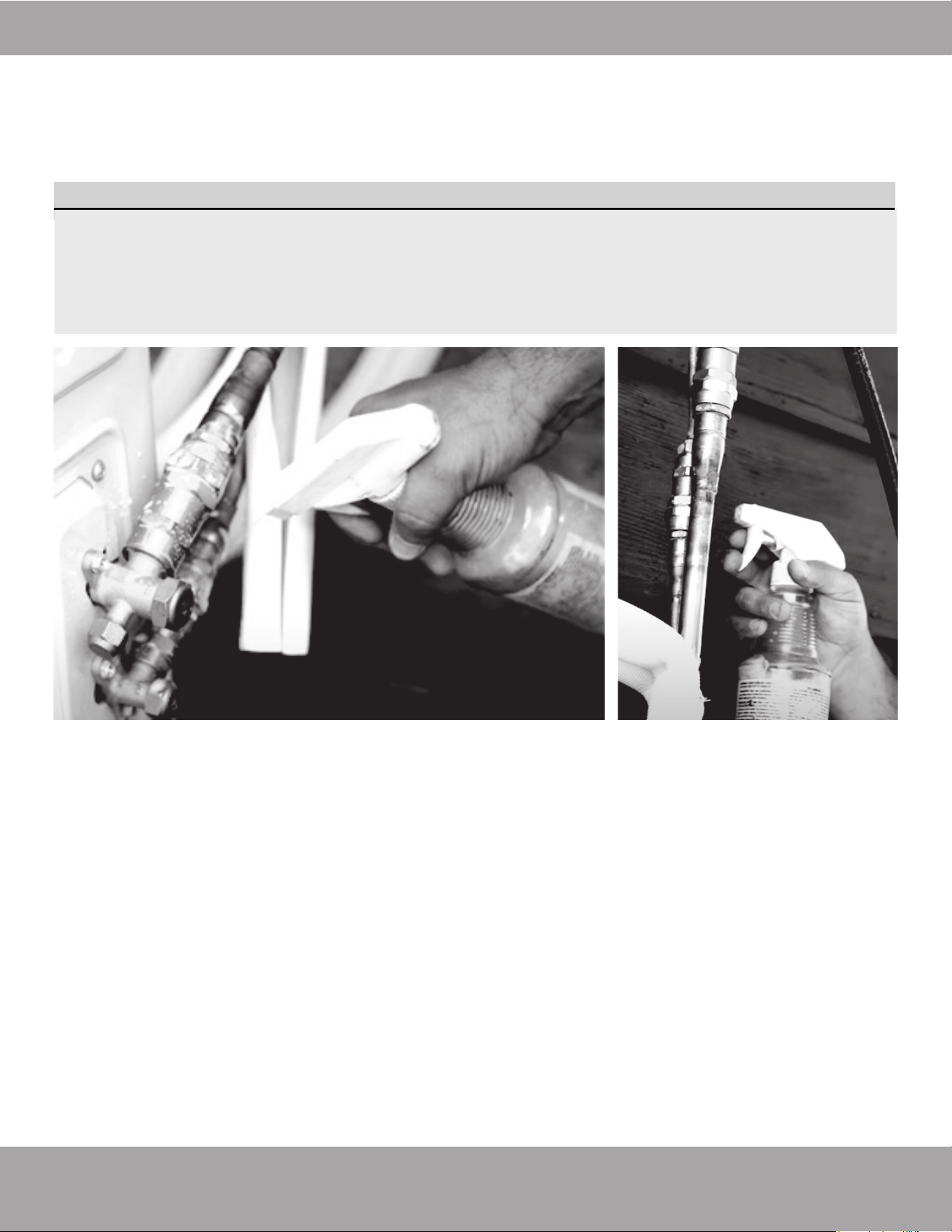
All of these steps must be completed BEFORE powering the unit, or else it could damage it.
IMPORTANT:
You will be asked to check for leaks at the piping connections multiple times throughout the
following steps of the installation, because the pressures within the lines will change once the unit
is turned on and this could reveal leaks not present during the initial check. These are imperative to
make sure your connections are not allowing refrigerant to escape the system. When checking for
leaks, if any bubbles form, it indicates the system has a leak and the screw connector needs to be
retightened. For more information about checking for leaks, please refer to the Electrical and Gas
Leak Checks section of the manual.
Refrigerant Piping Connection
Page 34
mrcool.com
4. After completing steps 1 and 2, you will now need to check all of the piping connections (at indoor unit and
outdoor unit) for leaks. You can do this by using leak detection spray, or applying a soapy water solution
(liquid detergent/water mixture) to the connection via a spray bottle or brush. If any bubbles begin to form,
that indicates there is a leak, and the connection needs to be re-tightened. Tighten the connection and
recheck it for leaks. Refer to Electrical and Gas Leaks Checks section of this manual for more information.
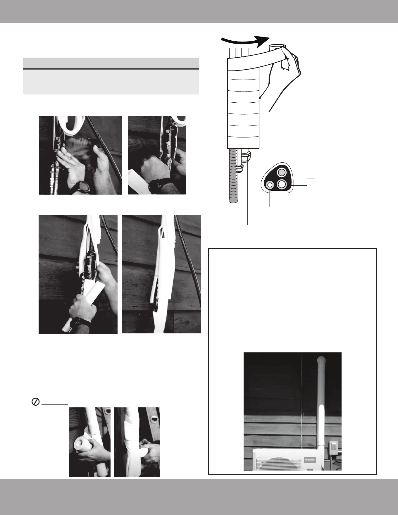
Page 35 mrcool.com
Refrigerant Piping Connection
IMPORTANT
1. Wrap the connectors at the indoor air handler
tightly with the supplied sound deadening pads.
Refrigerant
piping
Drain hose
Non-Adhesive U.V.
Tape
Fig. 7.2
Wrapping the piping
upward will prevent
rain/moisture from
seeping into the
overlaps of the tape
2. Now, place the supplied insulation material over the
connectors and exposed refrigrant piping
3. Now, starting where the line set is not covered with
the factory plastic (close to the indoor air handler
connection, you will wrap the line set upward to the
wall hole, using the supplied Non-adhesive U.V. tape.
This will cover the insulated line set connections,
cables, and drain hose. The drain pipe will need to be
at the bottom of the bundle (Refer to Fig. 7.2).
DO NOT wrap the end of the drain hose.
Do not complete these steps until all of the
refrigerant piping connections have been checked
for leaks.
If you would like the exterior piping on the
side of your home to have a sleeker, more
attractive look and add some extra protection
in the process, you can purchase a MRCOOL
®
LineGuard
®
Line Set Cover. This will encase
your refrigerant piping and lines, protecting
them from harsh weather conditions and sun
exposure, which will extend the life of your
system. These covers are available in various
sizes to fit your particular application.
Step 6: Wrap Piping Connections
In this step you will wrap and insulate the exposed line
connections coming from the indoor air handler.
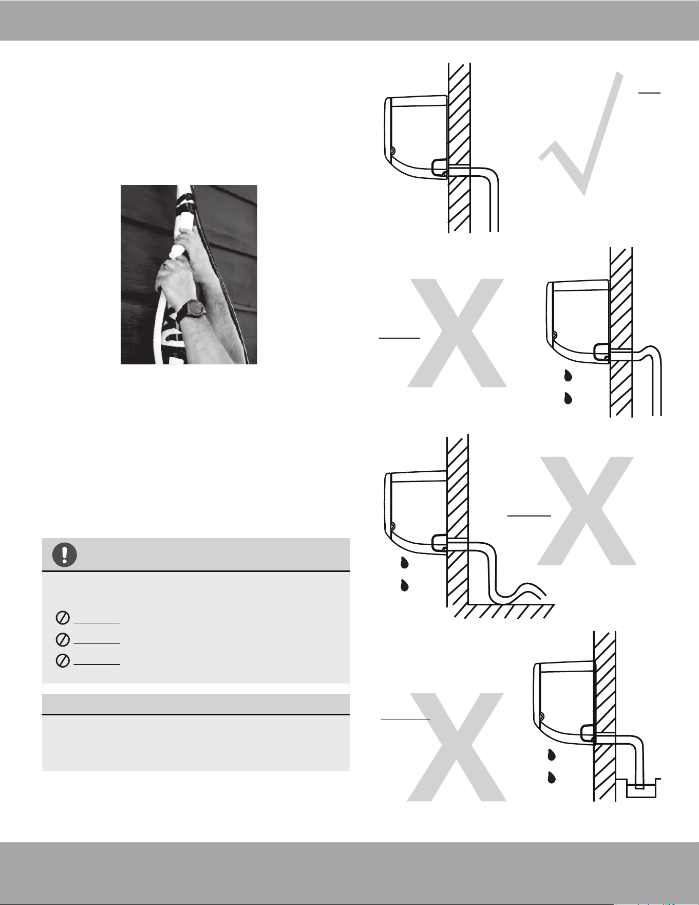
Page 36mrcool.com
Refrigerant Piping Connection
NOTE ON DRAIN HOSE PLACEMENT
Make sure to arrange the drain hose correctly
according to Fig. 7.3a.
DO NOT kink the drain hose.
DO NOT create a water trap.
DO NOT put the end of the drain hose in
water or a container that will collect water.
ENSURE UNUSED DRAIN HOLE IS PLUGGED
To prevent unwanted leaks, be sure that the
factory installed hollow center rubber plug is
installed in the unused drain hole.
Fig. 7.3a
Fig. 7.3b
Fig. 7.3c
Fig. 7.3d
Make sure there are NO
kinks or dents in the
hose to ensure proper
drainage.
NOT CORRECT
DENTS in the drain hose
will create water traps.
NOT CORRECT
KINKS in the drain hose
will create water traps.
NOT CORRECT
DO NOT place the end
of the drain hose in
water or in containers
that collect water.
This will prevent
proper drainage.
In this step you will connect the drain hose extension to
the drain hose exiting from the indoor unit that is within
the piping bundle you wrapped in the previous steps.
1. Securely connect the drain hose extension to the
drain piping from the indoor unit.
2. Using example Fig. 6.3a as a guide, make sure your
drain pipe is run in a similar manner. The other
examples in Fig 6.3 represent things you should
avoid when installing your drain pipe.
3. Remove the air filter from the indoor unit and pour a
small amount of water into the drain pan to ensure
that the water exits the bottom of the unit and flows
through the drain and drain pipe smoothly.
Step 7: Connect Drain Pipe
CAUTION
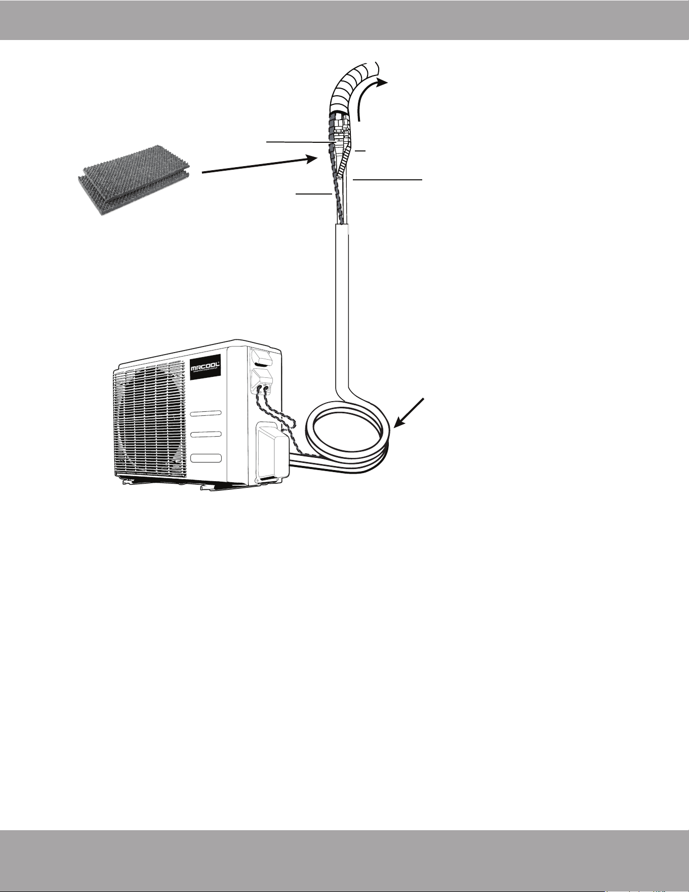
Page 37 mrcool.com
Refrigerant Piping Connection
Outdoor Unit (Exterior / Condenser)
MC Cable
Drainage Pipe
Wrap piping & connections
from indoor unit upward to
exterior wall hole
Quick Connect
®
Connections
Sound Deadening Pads
to wrap connections
once connected and
checked for leaks.
Coiled, excess
refrigerant line
Quick Connect® Line Set
(refrigerant pipe)
Pat. https://mrcool.com/mrcool-patents/
Quick Connect® Line Set
(refrigerant pipe)
Pat. https://mrcool.com/mrcool-patents/
8
Electrical Connections
Page 38mrcool.com
BEFORE PERFORMING ELECTRICAL WORK, READ THESE REGULATIONS
**NOTE: ELECTRICAL WORK MUST BE COMPLETED BY A QUALIFIED TECHNICIAN!**
DO NOT connect another appliance to the outlet for the unit. Only connect the unit to an
individual branch circuit outlet.
DO NOT allow wires to touch or rest against the refrigerant piping, compressor, or any other
moving parts within the unit.
1. All wiring must comply with local and national electrical codes, regulations, and must be installed by
a licensed electrician.
2. All electrical connections must be made according to the Electrical Connection Diagram located on
the panels of the indoor and outdoor units.
3. If there is a serious safety issue with the power supply, stop work immediately. Explain the issue to
the client, and refuse to continue the installation until the safety issue is properly resolved.
4. Power voltage should be within 90-110% of the rated voltage. An insufficient power supply can cause
a malfunction, electrical shock, and/or fire.
5. If connecting power to fixed wiring, a surge protector and main power switch should be installed.
6. The circuit, including any switches, should have a capacity 1.5 times the maximum unit current
(amps).
7. A qualified technician must use an approved circuit breaker or switch that disconnects all poles and
has a contact separation of at least 1/8 in (3 mm) incorporated in the fixed wiring.
8. Make sure the unit/system is properly grounded.
9. Every wire must be firmly and securely connected. Loose wiring can cause the terminal to overheat,
which could result in a malfunction and/or fire.
10. If the unit has an auxiliary electric heater, it must be installed as least 40 in (1 m) away from
combustible materials.
11. To avoid electrical shock, never touch the electrical components soon after the power supply has
been turned off. Always wait 10 minutes or more before touching the electrical components once the
power has been turned off.
13. Ensure that the electrical wiring and signal wiring do not cross. This could cause distortion and
interference.
14. The unit must be connected to the main outlet. Normally, the power supply must have an impedance
of 32 ohms.
15. Connect the outdoor wires before connecting the indoor wires.
*****BEFORE PERFORMING ANY ELECTRICAL WORK, TURN OFF ALL POWER TO THE SYSTEM!*****
NOTE: The wire colors of this series/model may differ from previous models, other series and
general conventions.
All wiring must be performed in accordance with the wiring diagram on the
back of the wiring cover of the outdoor condenser and/or the wiring diagrams found in this section
of the manual.
DO NOT MIX UP LIVE AND NULL WIRES
This is dangerous and can cause the air conditioning unit to malfunction. Make sure you clearly distinguish
the Live (”L”) Wires from the other wires.
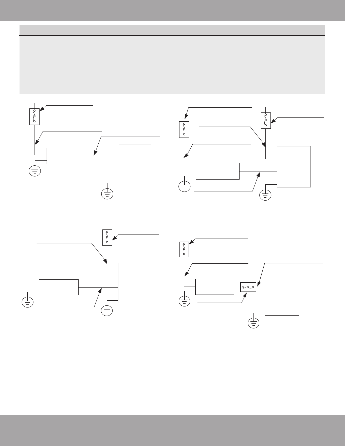
Page 39 mrcool.com
Electrical Connections
Indoor unit
Outdoor unit
Air switch
(purchased separately)
(purchased separately)
Outdoor unit
power wires
Indoor & Outdoor
connective wires
Indoor unit
Outdoor unit
Air switch
(purchased
separately)
(purchased separately)
Indoor unit
power wires
Indoor & Outdoor
connective wires
Indoor unit
Outdoor unit
Air switch
(purchased
separately)
Air switch
(purchased separately)
(purchased separately)
Indoor unit
power wires
Indoor & Outdoor
connective wires
Outdoor unit
power wires
Indoor unit
Outdoor unit
Air switch
Air switch
(purchased separately)
(purchased
separately)
(purchased
separately)
Outdoor unit
power wires
Indoor & Outdoor
connective wires
NOTE ON AIR SWITCH
When the maximum current of the air conditioner is more than 16A, an air switch or leakage
protection switch with protective device shall be used (purchased separately).
When the maximum current of the air conditioner is less than 16A, the power cord of the air
conditioner should be equipped with a plug.
Systems in the North American market should be wired according to NEC & CEC requirements and
regulations.
Please refer to the different air switch wiring diagrams Fig. 8.1 below:
NOTE: The diagrams above are illustration/reference purposes only
•
•
(B) (Only for the North America)(D)
(A) (C)
Fig. 8.1
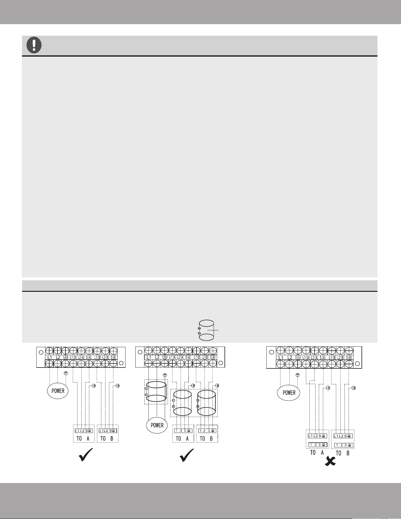
Page 40mrcool.com
Electrical Connections
CAUTION
NOTE: ELECTRICAL WORK MUST BE COMPLETED BY A QUALIFIED TECHNICIAN.
Connect the connective cables to the terminals, as identified below, with their matching numbers on
the terminal block of the indoor and outdoor units. Ensure that all screws and wires are securely
fastened to the terminal block. For example, in the US models shown in the following diagram,
Terminal L1(A) of the outdoor unit must connect with terminal 1 on the indoor unit. Continue to
match zone to zone for any additional connections.
See wiring diagrams on the following page for each type of system (Fig. 8.3 - 8.6 on the
following page) and take note of the following precautions:
• Always have an individual power circuit specifically for the air conditioner.
• Always follow the circuit diagram posted on the inside of the control cover.
• Check the specifications for the power source before proceeding.
• Confirm the starting voltage is maintained at more than 90 percent of the rated voltage listed on
the name plate.
• Confirm that the electrical capacity is sufficient.
• Confirm that the cable thickness is as specified in the power source specifications.
• Always install an earth leakage circuit breaker in wet or moist areas.
• The following can be caused by a drop in voltage; vibration of a magnetic switch, damaging the
contact point, broken fuses, and disturbance of normal functioning.
• Disconnection from a power supply must be incorporated into the fixed wiring. It must have an air
gap contact separation of at least 1/8 in (3 mm) in each active (phase) conductors.
• Before accessing terminals, all supply circuits must be disconnected.
• If using magnetic rings (optional - not supplied), you must use the correct magnetic rings on your
equipment to satisfy the EMC compulsory regulations required by the international standard CISPR
14-1:2005/A2:2011. Please make sure to apply the correct magnetic rings on the equipment
according to the wiring diagrams. Please contact your distributor or installer for further information.
NOTE
This product is designed to run on 60Hz frequency which is the North American standard. Run the
main power cord through the lower line-outlet of the cord clamp. Use a magnetic ring (not supplied,
optional part) to hitch the connective cable of indoor and outdoor units after installation. One
optional magnetic ring is used for one cable.
---- This symbol indicates field wiring.
This symbol indicates optional magnetic ring.
OPTIONAL
or
or
Correct Correct
Incorrect
Fig. 8.2
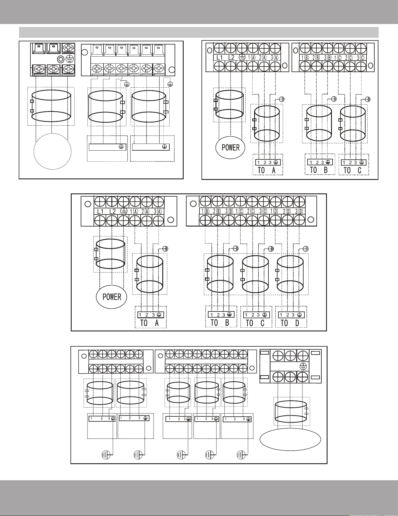
Fig. 8.6
Fig. 8.3 Fig. 8.4
Fig. 8.5
Page 41 mrcool.com
Electrical Connections
Wiring Diagrams
OPTIONAL
OPTIONAL
TO A TO B
L1 L2
OPTIONAL
POWER
SUPPLY
1 2 3 1 2 3
DIY-MULTI2-18HP230C (Up to 2 zones)
OPTIONAL
OPTIONAL
OPTIONAL
OPTIONAL
1(A)
3(A)
2(A) 1(B) 2(B)
3(B)
DIY-MULTI3-27HP230C (Up to 3 zones)
OPTIONAL
OPTIONAL
OPTIONAL
OPTIONAL
OPTIONAL
DIY-MULTI4-36HP230C (Up to 4 zones)
L2
L1
LPPUS REWOP Y
1(A)
2(A)
3(A)
1(B)
2(B)
3(B)
1(C) 2(C) 3(C) 1(D) 2(D) 3(D) 1(E) 2(E) 3(E)
TO A TO B
TO D
TO ETO C
OPTIONAL
OPTIONAL
OPTIONAL
OPTIONAL
OPTIONAL
OPTIONAL
DIY-MULTI5-48HP230C (Up to 5 zones)
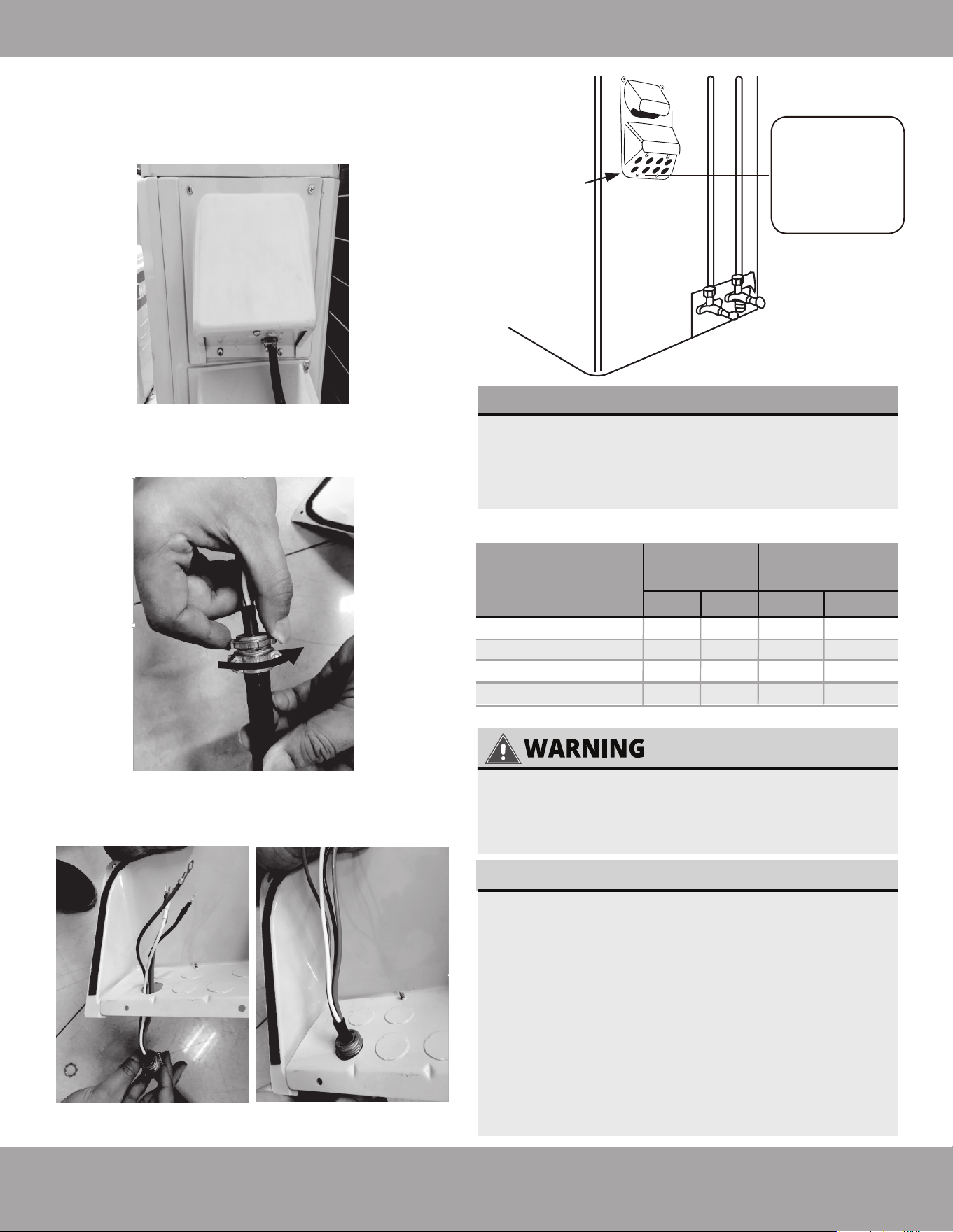
Page 42mrcool.com
Electrical Connections
ALL WIRING MUST BE INSTALLED STRICTLY IN
ACCORDANCE WITH THE WIRING DIAGRAM
LOCATED ON THE INSIDE OF THE OUTDOOR
CONDENSER WIRE COVER AS SHOWN IN FIG. 8.7.
The air conditioner’s circuit board (PCB) is
designed with a fuse to provide overcurrent
protection. The specifications of the fuse are
printed on the circuit board.
EXAMPLE (Indoor Unit): T3.15AL/250VAC,
T5AL/250VAC, T3.15A/250VAC, T5A/250VAC, etc.
EXAMPLE (Outdoor Unit):
T20A/250VAC (<24,000 Btu/h units),
T30A/250VAC (>24,000 Btu/h units), etc.
NOTE: For units with R32 or R290 refrigerant,
only the blast-proof ceramic fuse can be used.
NOTE ABOUT FUSE SPECIFICATIONS
3. Now, pull the end of the MC cable through the
hole of the electrical cover you removed earlier.
Please refer to the images below.
1. Remove the screws from the electrical wiring
cover from the outdoor condenser, as shown in
the image below and Fig. 8.7, and remove it.
2. Remove the retaining nut from the end MC cable
that you fed through the wall hole earlier in the
installation
, as shown in the image below.
Cover
Outdoor Unit
Wiring Diagram
is located on
the inside of the
wire cover on
the outdoor unit.
Fig. 8.7
Connect the MC Cable(s) to Outdoor Condenser
SELECT THE CORRECT CABLE
•
See table below for gauge requirements
NOTE: The table below is a standard chart, the
AWG ratings and wiring needs will change based
on wire length and temperature.
Appliance
Amps (A)
AWG
25
40
45
36K
27K
18K
Model Series
Minimum Wire Gauge for Power Cables
MCA MOP Min. Pref.
12
10
8
10
8
6
18
26
27
6048K 8 640
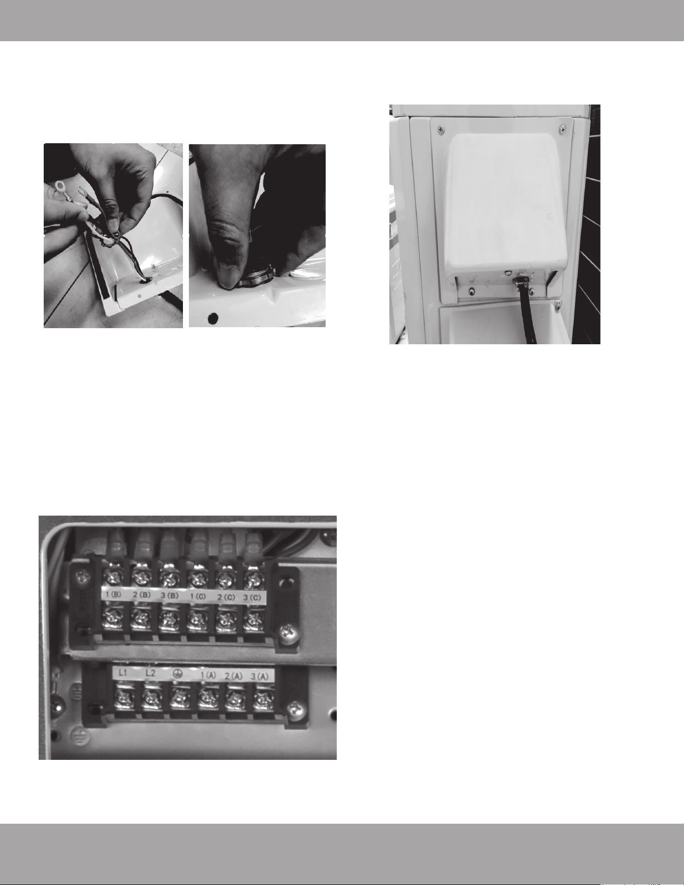
Page 43 mrcool.com
Electrical Connections
4. Now, secure the MC cable to the electrical cover
by pushing the threaded end of the cable into the
hole and reinstalling the retaining nut previously
removed. Please refer to the images below.
Continue to do this for each of the MC cables
coming from each of the air handlers installed.
5. Then, you will connect the wires to the terminal
block. Each wire should be numbered and
correspond with a connection port on the terminal
block. Match up each wire with the correct port,
and firmly screw the u-lug of each wire to its
corresponding terminal. Now, screw the ground
wire into the bottom screw of the terminal block,
as shown in the image below. Continue to do this
with all of the MC cables from each of the air
handlers, using the wiring diagram for your system
on the previous pages as a guide, until they are all
connected to the condenser.
6. Finally, reinstall the electrical wiring cover and
secure it using by reinstalling the screws you
previously removed.
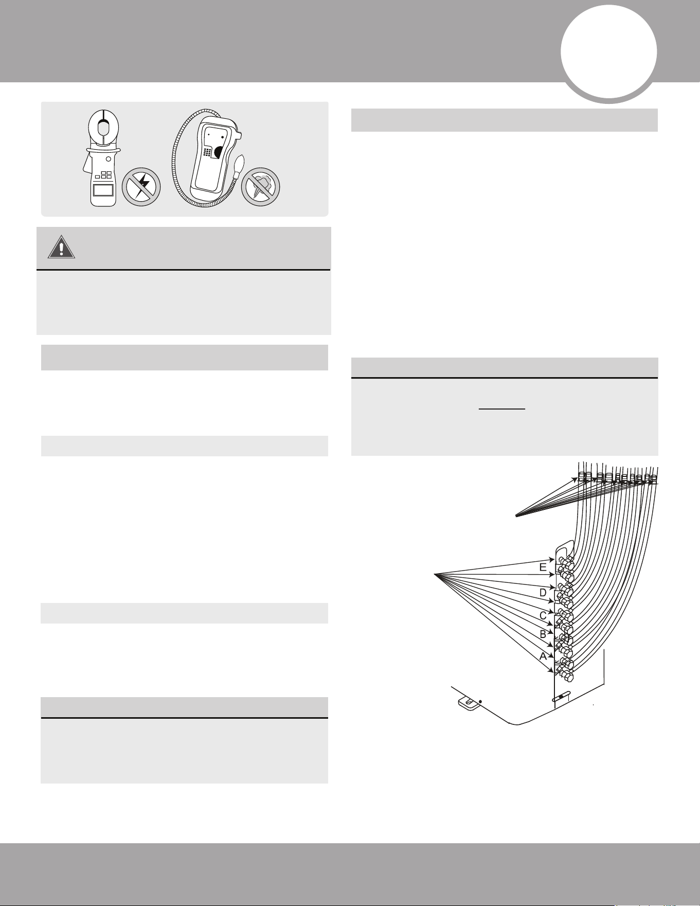
Page 44mrcool.com
Refrigerant Piping Connection
AFTER PERFORMING GAS LEAK CHECKS
After confirming that all of the refrigerant pipe
connections points DO NOT leak, replace the
valve cover on the outside unit and wrap and
insulate the piping connections of the
indoor unit.
8
BEFORE TEST RUN
9
Using a soft brush or spray bottle, apply a soapy
water solution to all of the pipe connection points of
the indoor and outdoor units, watching to see if any
bubbles form. The presence of bubbles indicates
there is a leak.
There are two different methods to check for
gaseous leaks. Use Fig. 9.1 below as a guide for
the critical points to check for leaks.
Soap and Water Method
Leak Detector Method
If using a leak detector, refer to the device’s
operation/instruction manual for proper usage
instructions.
Gas Leak Checks
Electrical and Gas Leak Checks
IF ELECTRICAL LEAKAGE IS DETECTED
If electrical leakage is detected, turn off the
unit immediately and call a licensed
electrician to find and resolve the cause of
the leakage.
After installation is complete, confirm that all
electrical wiring has been installed in accordance
with local and national regulations, and according
to the installation manual.
Check Insulated Resistance
The insulated resistance must be more than 2MΩ.
Check Grounding Work
Measure grounding resistance by visual detection
and with a grounding resistance tester. Grounding
resistance must be less than 0.1Ω.
NOTE: This may not be required for some
locations in North America.
Check for Electrical Leakage
During the Test Run, use an electroprobe and
multimeter to perform a comprehensive electrical
leakage test.
NOTE: This may not be required for some
locations in North America.
Electrical Safety Checks
DURING TEST RUN
WARNING – RISK OF
ELECTRICAL SHOCK
ALL WIRING MUST BE INSTALLED BY A
LICENSED ELECTRICIAN AND COMPLY WITH
LOCAL, STATE, AND NATIONAL ELECTRICAL
CODES.
Fig. 9.1
Indoor unit
check points
Outdoor unit
check points
NOTE: The illustration above is for demonstration
purposes only. The actual order of the A, B, C, D,
and E valves on your system may be slightly
different from what is shown, however, the
general shape will remain the same.
Page 45 mrcool.com
Refrigerant Piping Connection
Before Test Run
Test Run Instructions
The indoor & outdoor units are properly
installed
Unit is properly grounded
All wiring & electrical terminals are properly
covered & connected
The power voltage is the correct voltage for
the unit
Wall Hole Sleeve is packed airtight
All refrigerant piping connection points
DO NOT leak
Water drains properly from drain pipe
All piping is properly insulated
Ensure there are no obstacles near the inlet
and outlet of the outdoor or indoor units
Ensure all connection valves and King valves
on the outdoor condenser are fully opened
List of Checks to Perform Before Test Run
Test Run
10
You should perform the Test Run for at least 30
minutes.
1. Connect power to the unit. Then, turn on the main
power switch and allow the unit to warm up.
2. Press the ON/OFF button on the remote
controller to turn on the system.
3. Press the MODE button to scroll through the
following functions, one at a time:
• COOL - Select the lowest possible temperature
• HEAT - Select the highest possible temperature
4. Let each function run for 5 minutes and then
perform the checks listed in the table below.
Failure to perform the test run could result in
damage to the unit, property, or personal injury.
Only perform test run after you have ensure the
following steps have been completed:
• Electrical Safety Checks - Confirm that the
unit’s electrical system is safe and operating
properly.
• Gas Leak Checks - Check all refrigerant
piping/line set connections and confirm that
the system is not leaking.
• Confirm that the gas and liquid (high and low
pressure) stop valves are fully open. If the valves
are not fully opened before the system is
turned on, damage could occur.
A test run must be performed after the entire
system has been completely installed. Complete and
confirm the list of checks below before performing a
test run.
List of Checks to Perform During Test Run
•
•
•
Ensure the remote control functions properly
Ensure the louvers move properly and can be
adjusted using the remote control
Ensure the room temperature is being
registered/displayed correctly
Ensure the indicators on the remote control
and the display panel of the indoor unit
function properly
Check to see that the drainage system
unimpeded and draining smoothly
Ensure there is no vibration or abnormal
noise during operation
Ensure the manual buttons of the indoor air
handler function properly
Ensure refrigerant piping connections
DO NOT leak
Ensure there is no vibration or abnormal
noise during operation
Ensure the wind, noise, and water generated
by the unit DO NOT pose a safety hazard or
cause a disruption to your neighbors
For Indoor Unit
For Outdoor Unit
•
•
•
•
•
•
•
•
•
•
•
•
•
•
•
•
•
NOTE: If the unit malfunctions or does not
operate correctly, please refer to the
Troubleshooting section of this manual before
contacting technical support.
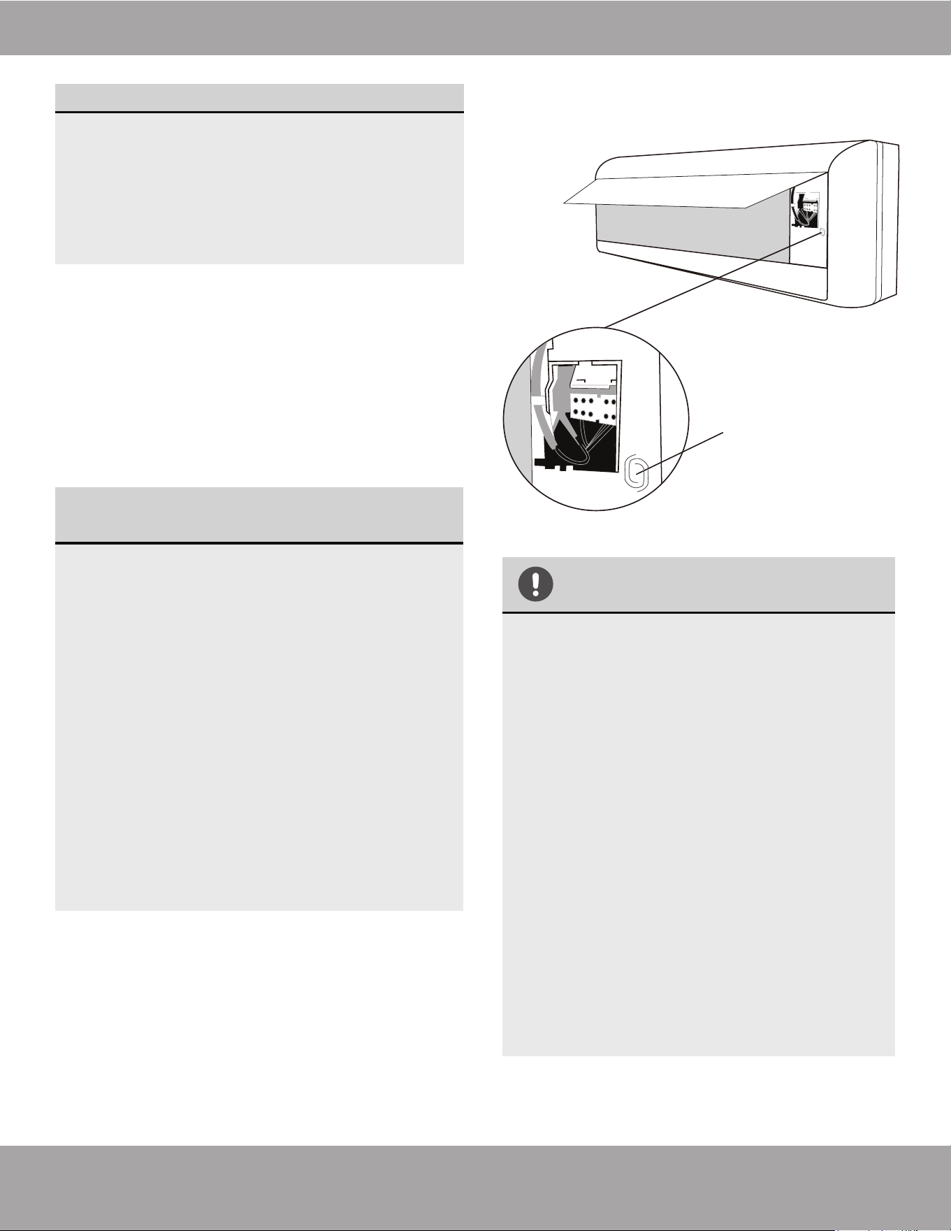
Page 46mrcool.com
Test Run
DOUBLE-CHECK PIPE CONNECTIONS
IF THE AMBIENT TEMPERATURE IS
BELOW 63°F (17°C)
THANK YOU
Fig. 10.1
Manual Control
Button
During operation, the pressure of the refrigerant
circuit/piping will increase. This may reveal leaks
that were not present during your initial leak
check. Take time during the Test Run to
double-check that all refrigerant pipe connection
points do not have leaks. Refer to Gas Leak
Check section for instructions.
If the ambient temperature is below
63°F (17°C), the remote controller cannot be
used to turn on the COOL function. In this
instance, you will need to use the MANUAL
CONTROL BUTTON to test the COOL
function. Follow the steps below to access
this function:
Lift the front panel of the indoor unit, and
continue to raise it until it clicks into
place and becomes self-supporting.
The MANUAL CONTROL BUTTON is located
on the right-hand side of the unit (Refer
to Fig 10.1). Press it 2 times to select the
COOL function.
Perform Test Run as normal.
1.
2.
3.
Thank you for purchasing a MRCOOL
®
ductless mini-split heating and air
conditioning product.
MRCOOL
®
is a young, family-owned
company, so we are truly thankful you
trusted us with your business. Should you
ever need technical support, or just have
questions about your MRCOOL
®
product, or
any of the other products we offer, please
do not hesitate to call us at (270)-366-0457.
Also, if you can spare a few minutes today,
and leave a review of your new MRCOOL
®
product on the partner site where you
purchased it, it would really mean a lot to
us. We are always looking for ways to
improve, and real reviews, from actual
customers like yourself, are vital and
invaluable to our growing company.
Thank you for being a valued customer!
5. After the Test Run is successfully completed, and
you confirm all check points in List of Checks to
Perform have passed, do the following:
a. Using the remote control, return unit to normal
operating temperature.
b. Using insulation tape, wrap the indoor
refrigerant pipe connections that you left
uncovered during the indoor unit installation
process.
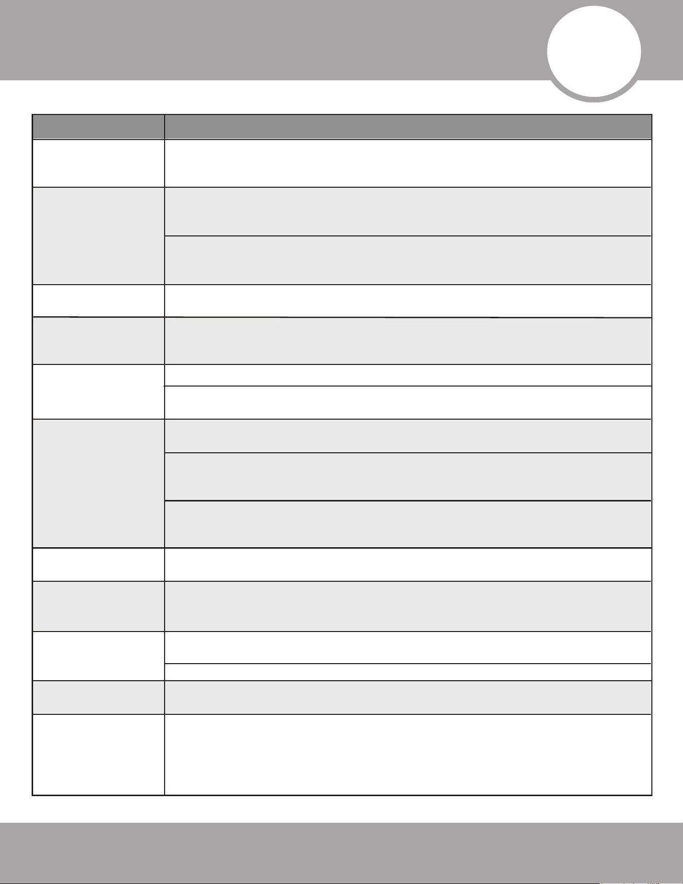
mrcool.com
11
The following events may occur during normal operation, and may not indicate a
malfunction.
Symptom
Cause
Page 47
The unit may change its setting to prevent frost from forming on the unit. Once
the temperature increases, the unit will start operating in the previously selected
mode again.
Once the set temperature has been reached, at this point the unit turns off the
compressor. The unit will continue operating when the temperature fluctuates
again.
The unit changes
from COOL/HEAT
mode to FAN mode.
The indoor unit
emits white mist.
In humid regions, a large temperature difference between the room’s air and the
conditioned air can cause a white mist to occur.
Indoor and outdoor
units emit a white
mist.
When the unit restarts in HEAT mode after defrosting, a white mist may be
emitted due to moisture generated from the defrosting process.
The indoor unit
makes noises.
Indoor unit and
outdoor unit make
noises.
The outdoor unit
makes noises.
Dust is emitted from
the indoor or
outdoor unit.
The unit emits a bad
odor.
Outdoor unit fan
does not operate.
Operation is erratic,
unpredictable, or
unit is unresponsive.
The sound of rushing air may occur when the louver resets it’s position.
A squeaking sound may occur after running the unit in HEAT mode due to the
expansion and contraction of the unit’s plastic parts.
A low hissing sound during operation: This is normal and is caused by refrigerant
gas flowing through both indoor and outdoor units.
A low hissing sound when the system starts, has just stopped running, or is
defrosting: This noise is normal and is caused by the refrigerant gas changing
direction or stopping.
Squeaking sound: Normal expansion and contraction of the plastic and metal
parts caused by temperature changes during operation can cause squeaking
noises.
The unit will make different noises based on which mode it is currently operating
in.
The unit may accumulate dust during extended periods of not being used, which
will be emitted when the unit is turned on. This can be mitigated by covering the
unit during any long periods of inactivity.
The unit may absorb odors from the environment (such as furniture, cooking,
cigarettes, etc.) which will be emitted during operations.
The unit’s filters have become moldy and should be cleaned.
During operation, the fan speed is controlled to optimize product operation.
Interference from cell phone towers and remote boosters may cause the unit to
malfunction.
If this is the case, try the following:
• Disconnect the power, then reconnect.
• Press ON/OFF button on remote control to restart operation.
Unit does not turn
on when pressing
ON/OFF button.
The unit has a 3 minute protection feature that prevents the unit from
overloading. The unit cannot be restarted within 3 minutes of being turned off.
NOTE: If problem persists, contact a local dealer or your nearest customer service center. Provide them with a
detailed description of the unit malfunction as well as the model number of your unit.
Troubleshooting
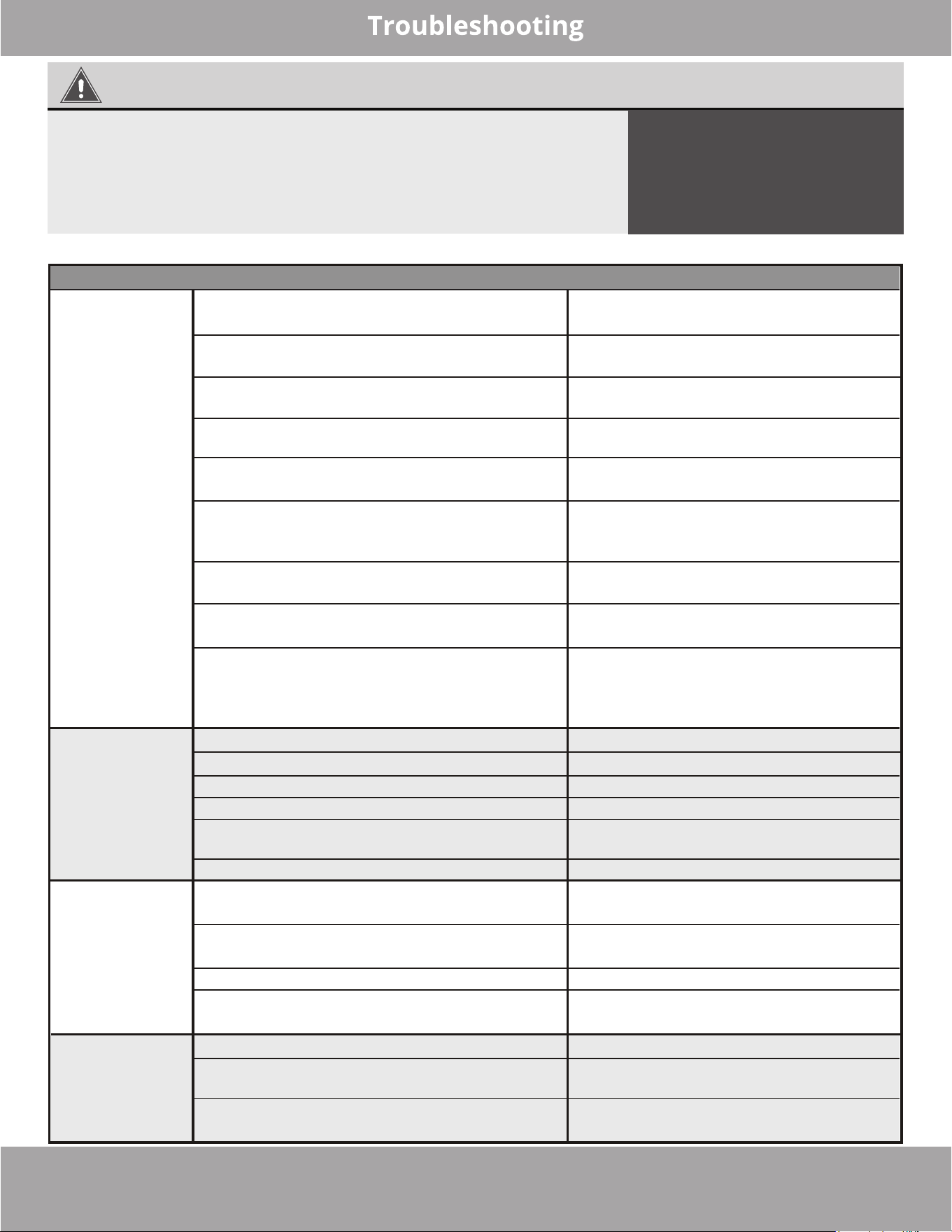
Page 48mrcool.com
Before calling for service assistance, troubleshoot a problem by performing the following checks:
WARNING
· Signal/power cable is damaged or abnormally warm
· Burning odor
·
Loud or abnormal sounds
·
A power fuse or circuit breaker trips frequently
·
Water or other objects fall into or out of the unit
DO NOT ATTEMPT TO CORRECT
OR FIX THESE ITEMS YOURSELF!
CONTACT AN AUTHORIZED
SERVICE PROVIDER
IMMEDIATELY!
In the case of any of the following, turn off the unit immediately!
Poor Cooling
Performance
The unit is
not working
The unit starts
and stops
frequently
Poor heating
performance
Symptom SolutionPossible Causes
The heat exchanger on the indoor or
outdoor unit is dirty.
The air filter is dirty.
The air inlet or outlet of either unit is
blocked.
Doors and windows are open.
Excessive heat is generated by sunlight.
Too many other sources of heat in the
room (people, computers, electronics, etc.)
Low refrigerant due to a leak or long-term
use.
SILENCE function is activated (optional
feature).
Power failure Wait for power to be restored
Turn on the power
Replace the fuse
Replace the batteries
Wait three minutes after restarting
the unit
Turn timer off.
Check for leaks and recharge the
system with refrigerant.
Evacuate and recharge the system
with refrigerant.
The power is turned off
The fuse is burned out
Remote control batteries are dead
The unit’s 3 minute protection feature has
been activated
Timer is activated
There’s too much or too little refrigerant
in the system
Incompressible gas or moisture has
entered the system.
The compressor is broken.
The voltage is too high or too low.
The outdoor temperature is extremely low.
Cold air is entering through doors and
windows
Low refrigerant due leak or long-term use
Replace the compressor.
Install a manostat to regulate the
voltage.
Use auxiliary heating device.
Make sure that all doors and windows
are closed during use.
Check for leaks, re-seal if necessary
and top off refrigerant
Clean the affected heat exchanger
Remove the filter and clean it
according to the instructions.
Turn the unit off, remove the
obstruction and turn it back on.
Ensure all windows and doors are
closed while operating the unit.
Close windows and curtains during
periods of high heat or bright
sunshine.
Reduce the amount of heat sources
Check for leaks, reseal if necessary
and top off the refrigerant level.
The SILENCE function can lower
product performance by reducing
operating frequency. Turn off the
SILENCE function.
Temperature setting may be higher than
ambient room temperature.
Lower the temperature setting
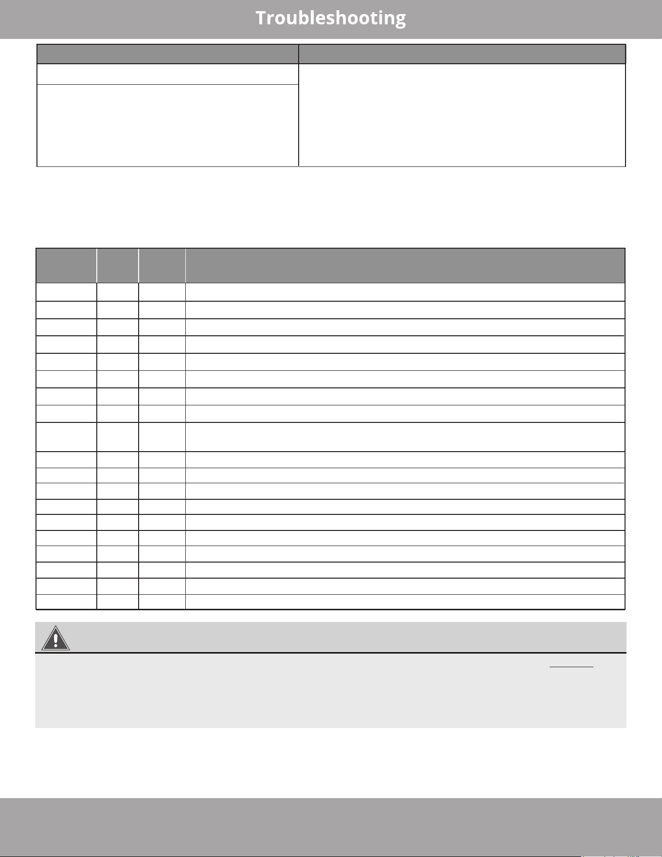
Page 49 mrcool.com
Indicator lamps continue flashing
Error code appears and begins with the
letters, as shown below in window display
of the indoor unit:
• EH(xx), EL(xx), EC(xx)
• PC(xx)
Symptom Solution
The unit may stop operation or continue to run
safely. If the indicator lamps continue to flash or
error codes appear, wait for roughly 10 minutes. The
problem may resolve itself. If not, disconnect the
power, then connect it again. Turn the unit on. If the
problem persists, disconnect the power and contact
your nearest customer service center.
Operation
Lamp
Timer
Lamp
LED
Display
Error Information
1 time OFF
EH 00
Indoor unit EEPROM parameter error.
2 times OFF
EL 01
Indoor / outdoor unit communication error.
3 times OFF
EH 02
Zero-crossing signal detection error (for some models).
4 times OFF
EH 03
The indoor fan speed is operating outside of the normal range.
5 times OFF
EC 51
Outdoor unit EEPROM parameter error.
5 times OFF
EC 52
Condenser coil temperature sensor T3 is in open circuit or has short circuited.
5 times OFF
EC 53
Outdoor room temperature sensor T4 is in open circuit or has short circuited.
5 times OFF
EC 54
Compressor discharge temperature sensor TP is in open circuit or has short circuited.
5 times OFF
EC 56
Evaporator coil outlet temperature sensor T2B is in open circuit or has short-circuited
(for free-match indoor units).
6 times OFF
EH 60
Indoor room temperature sensor T1 is in open circuit or has short circuited.
6 times OFF
EH 61
Evaporator coil temperature sensor T2 is in open circuit or has short circuited.
12 times OFF
EC 07
The outdoor fan speed is operating outside of the normal range.
7 times FLASH
PC 00
IPM malfunction or IGBT over-strong current protection.
2 times FLASH
PC 01
Over voltage or over low voltage protection.
3 times FLASH
PC 02
High temperature protection of IPM module/compressor, or high pressure protection.
5 times FLASH
PC 04
Inverter compressor drive error.
1 time FLASH
PC 08
Current overload protection.
7 times FLASH
PC 03
High pressure protection or low pressure protection.
1 times ON
--
Indoor units mode conflict (match with multi outdoor unit).
Indoor Unit Error Code Display
When the indoor unit encounters a recognized error, the operation LED will flash in a corresponding series,
the timer LED may turn on or begin flashing, and an error code will be displayed. These error codes are
described in the table below:
WARNING
The error codes above and descriptions on the following pages are for reference only. DO NOT
attempt these repairs yourself, as doing this could cause personal injury, damage to your unit,
and/or void the warranty. Should your unit display any of the error codes above, turn off the unit
and contact the MRCOOL technical department at (270) 366-0457 for more information or a
qualified service technician to investigate the matter further.
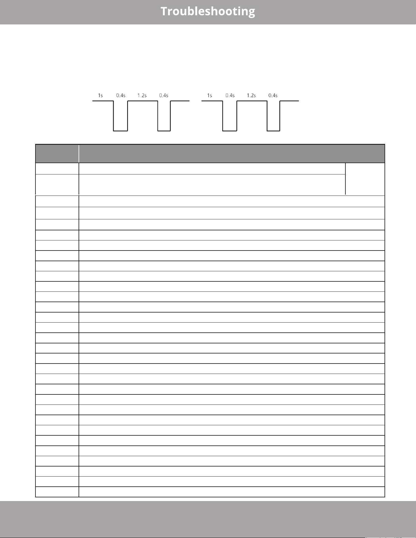
mrcool.com Page 50
For other errors:
The display board may show a garbled code or a code undefined by the service manual. Ensure that this code is
not a temperature reading.
Troubleshooting:
Test the unit using the remote control. If the unit does not respond to the remote, the indoor PCB requires
replacement. If the unit responds, the display board requires replacement.
Display (88) flash frequency:
Outdoor Unit Error Code Display
Display Malfunction or Protection
df
Defrosting
Normal
Display, not
an error
code
FC
Forced cooling
EC 51
Outdoor EEPROM malfunction
EL 01
Indoor / outdoor units communication error
PC 40
Communication malfunction between IPM board and outdoor main board
PC 08
Outdoor overcurrent protection
PC 10
Outdoor unit low AC voltage protection
PC 11
Outdoor unit main control board DC bus high voltage protection
PC 12
Outdoor unit main control board DC bus high voltage protection /341 MCE error
PC 00
IPM module protection
PC 0F
PFC module protection
EC 71
Over current failure of outdoor DC fan motor
EC 72
Lack phase failure of outdoor DC fan motor
EC 07
Outdoor fan speed has been out of control
PC 43
Outdoor compressor lack phase protection
PC 44
Outdoor unit zero speed protection
PC 45
Outdoor unit IR chip drive failure
PC 46
Compressor speed has been out of control
PC 49
Compressor overcurrent failure
PC 30
High pressure protection
PC 31
Low pressure protection
PC 0A
High temperature protection of condenser
PC 06
Temperature protection of compressor discharge
PC 02
Top temperature protection of compressor
EC 52
Condenser coil temperature sensor T3 is in open circuit or has short circuited
EC 53
Outdoor room temperature sensor T4 is in open circuit or has short circuited
EC 54
Compressor discharge temperature sensor TP is in open circuit or has short circuited
EC 56
Evaporator coil outlet temperature sensor T2B is in open circuit or has short circuited
EC 50
Open or short circuit of outdoor unit temperature sensor(T3,T4.TP)
LC 06
IPM module frequency limit shutdown/IPM high temperature protection
PC 0L
Low ambient temperature protection
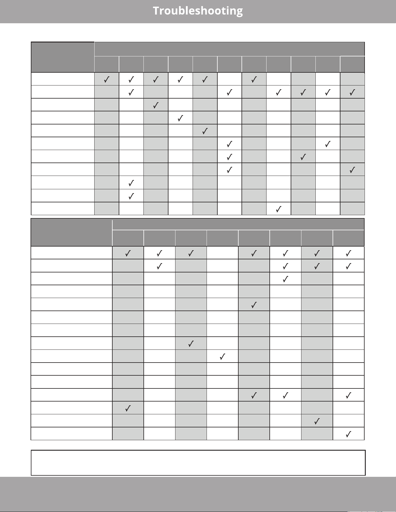
mrcool.com Page 51
Troubleshooting by Error Code
Disclaimer: The error codes and descriptions are for reference only. If your system displays
any of these codes contact the MRCOOL technical department for more information or a
qualified service technician to investigate the issue further.
Parts that
could be
causing the issue
Error Code
EH 00 EL 01 EH 03 EH 60 EH 61
(O)EC
50
EH 02 PC 02 EC 53 EC 52
EC 54
Indoor PCB
x x x x x
Outdoor PCB x x x x x
Indoor fan motor x x x x x x x x x x
T1 sensor x x x x x x x x x x
T2 Sensor x x x x x x x x x x
T3 Sensor x x x x x x x x x
T4 Sensor x x x x x x x x x
TP Sensor x x x x x x x x x
Reactor x x x x x x x x x x
IPM module board x
x x x x x x x x x
Over load protector x x x x x x x x x x
Parts that
could be
causing the issue
Error Code
PC 40 EC 72 PC 43 PC 45 (O) PC 06 (O) PC 0A (O) PC 30
PC 03/
(O) PC 31
Outdoor PCB
x
Outdoor fan motor x x x x
T3 Sensor x x x x x x x
T4 Sensor x x x x x x x x
TP Sensor x x x x x x x
T2B Sensor x x x x x x x x
Reactor or inductance x x x x x x x x
Compressor x x x x x x x
IPM module board x x x x x x x
Bridge rectifier x x x x x x x x
PFC module x x x x x x x x
Additional refrigerant x x x x x
Electric control box x x x x x x x
High pressure switch x x x x x x x
Low pressure switch x x x x x x x
The codes and parts listed below represent what parts could be associated with the error code.
(O) represents the error code being displayed on the outdoor unit.
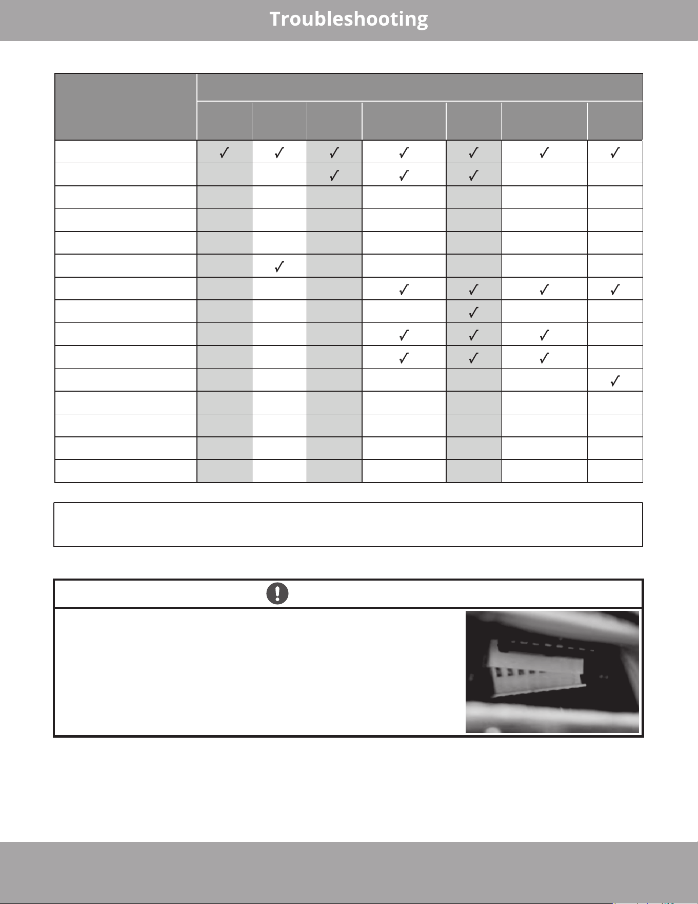
mrcool.com Page 52
Parts that
could be
causing the issue
Error Code
EC 51
EC 56
EC 07/
(O) EC 71
PC 08/
(O) PC 44/
PC 46/PC 49
PC 00/
PC 04
PC 01/
(O) PC 10
PC 11/ PC 12
(O) PC 0F
Outdoor PCB
Outdoor fan motor x x x x
T3 Sensor x x x x x x x
T4 Sensor x x x x x x x
TP Sensor x x x x x x x
T2B Sensor x x x x x x
Reactor or inductance x x x
Compressor x x x x x x
IPM module board x x x x
Bridge rectifier x x x x
PFC module x x x x x x
Additional refrigerant x x x x x x x
Electric control box x x x x x x x
High pressure switch x x x x x x x
Low pressure switch x x x x x x x
(O) represents the error code being displayed on the outdoor unit.
Disclaimer: The error codes and descriptions are for reference only. If your system displays
any of these codes contact the MRCOOL technical department for more information or a
qualified service technician to investigate the issue further.
IMPORTANT!
If the error code “F6” appears during initial start up on a
newly installed unit, this could be caused by a loose wiring
connector on the circuit board of the outdoor condenser
due to shipping & handling (please refer to the image to
right). Reconnect the connector and ensure it is properly
seated to resolve the issue.
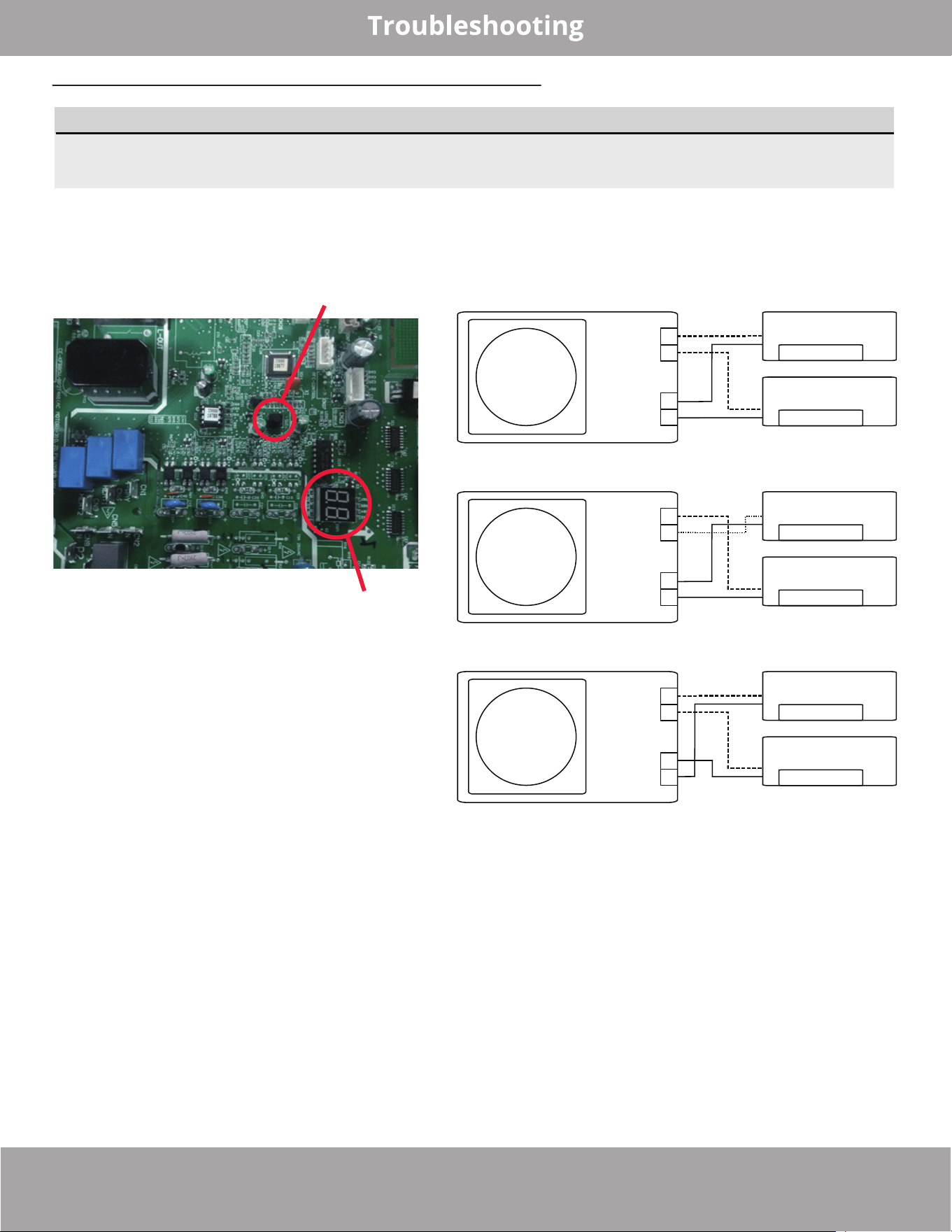
Page 53
mrcool.com
Automatic Wiring/Piping Correction Function
Newer models now feature automatic correction of wiring/piping errors. Press the"check switch" on the
PCB board of the outdoor unit for 5 seconds until the LED displays "CE.” This indicates that this function is
working. Approximately 5-10 minutes after the switch is pressed, the "CE" will disappear, meaning that the
wiring/piping error is corrected and all of the wiring/piping is properly connected.
NOTE
The function for the automatic wiring/piping correction illustrated below is intended for use by a
licensed electrical technician only.
How To Activate This Function
1. Check that outside temperature is above 41°F
(5°C). This function does not work when outside
temperature is not above 41°F (5°C).
2. Check that the stop valves of the liquid pipe
and gas pipe are open.
3. Turn on the breaker and wait at least 2
minutes.
4. Press the check switch on the outdoor PCB
board unit LED display "CE".
Correct
Terminal
block
Liquid/
Gas pipe
Outdoor unit
Indoor unit B
Indoor unit A
B
A
B
A
Incorrect wiring
Terminal
block
Liquid/
Gas pipe
Outdoor unit
Indoor unit B
Indoor unit A
B
A
B
A
Incorrect wiring
Terminal
block
Liquid/
Gas pipe
Outdoor unit
Indoor unit B
Indoor unit A
B
A
B
A
Check switch
LED display
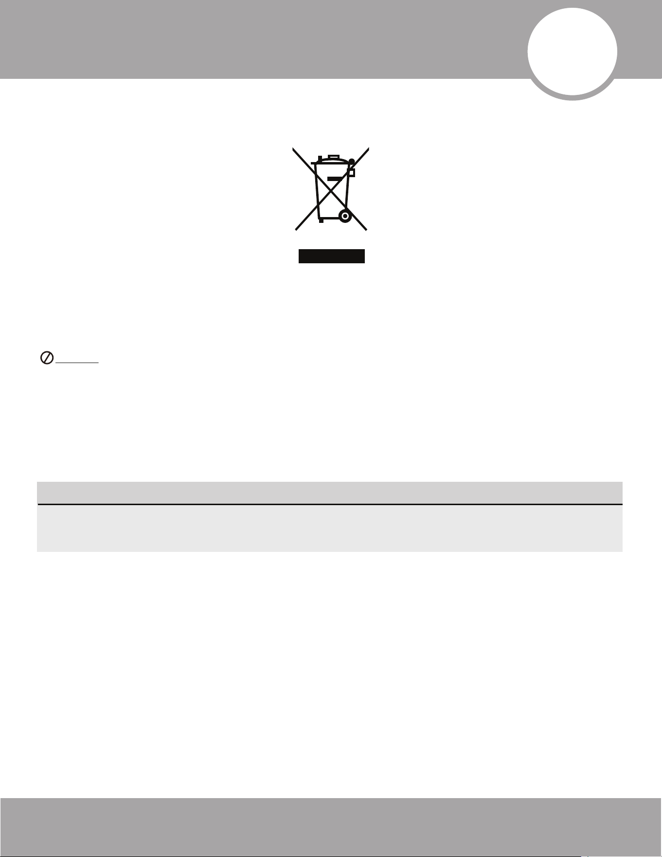
Page 54mrcool.com
Refrigerant Piping Connection
12
EU Disposal Guidelines
Special notice
Correct Disposal of This Product (Electrical Waste & Electronic Equipment)
This appliance contains refrigerant and other potentially hazardous materials. When disposing of this appliance,
the law requires special collection and treatment.
DO NOT dispose of this product as household waste or unsorted municipal waste.
When disposing of this appliance, you have the following options:
• Dispose of the appliance at a designated municipal electronic waste collection facility.
• When buying a new appliance, the retailer will receive the old appliance free of charge.
• The manufacturer will receive the old appliance free of charge.
• Sell the appliance to certified scrap metal dealers.
The marking shown below when depicted on the product or its literature, indicates that electrical
waste and electrical equipment should not be mixed with general household waste.
Disposing of this appliance in the forest or other natural surroundings endangers your health and is
bad for the environment. Hazardous substances may leak into the ground water and enter the food
chain.

Due to updates and constantly improving performance, the information and instructions within this
manual are subject to change without notice. Please visit www.mrcool.com/documentation to
ensure you have the latest version of this manual.
DIY
®
Multi-Zone