
Please read this manual carefully before installation and keep it for future reference.
Copyright © 2021 MRCOOL, LLC
Thank you for choosing MRCOOL Please read this manual carefully before installation and keep it for future reference.
Owner’s Manual
Universal
®
Series
DC Inverter / Condenser (Cooling Only)
MDUCO18*
Due to updates and constantly improving performance, the information and instructions within this
manual are subject to change without notice. Please visit www.mrcool.com/documentation to
ensure you have the latest version of this manual.
Version Date: 10-25-21
Contents
Page 1 mrcool.com
MC MC
EU Disposal Guidelines ...... 43
5
Post Installation Checks ........... 32
3
Maintenance
...............................
34
1. Troubleshooting ....................................... 34
2. Error Codes ............................................... 36
3. Unit Maintenance .................................... 37
4. Notice on Maintenance .......................... 39
5. After Sales Services ................................. 42
4
Unit Installation ........................... 9
1. Installation Location.................................... 9
3. Conventional Line Set Installation.......... 15
4. No-Vac
®
Quick Connect
®
* Installation . 24
2. Outdoor Installation ................................. 14
7. Electrical Connection.................................. 27
5. Installation of Drain Pipe........................... 25
6. Condenser Field Conversion.................... 26
2
1. Introduction .................................................................. 5
2. Accessories .................................................................. 6
4. Unit Dimensions .......................................................... 7
1
Appliance Overview ................................. 5
Safety Precautions ................................... 2
!
3. Operating Range .......................................................... 7
*Pat. https://mrcool.com/mrcool-patents/

Page 2
Safety Precautions
mrcool.com
WARNING
Please read the manual in its entirety before installing, operating or repairing.
DO NOT share the electrical circuit with other appliances. Improper or insufficient power
supply can cause fire or electrical shock.
DO NOT let other substances or gases enter the unit when connecting refrigerant piping.
The presence of other gases or substances will lower the unit’s capacity, and could cause
abnormally high pressure in the operation cycle. This could cause an explosion and/or
personal injury.
DO NOT connect the ground wire to a gas pipe, water pipe, lightning arrester, or telephone
wire.
DO NOT allow children to play with the air conditioner. Children should be supervised
around the unit at all times.
DO NOT alter the settings of the pressure sensor or other protective devices; if
short-circuited or modified, fire and/or an explosion could occur.
Installation must be performed by an authorized technician. Improper installation could cause
water leakage, electrical shock, and/or fire.
Installation must be performed according to installation instructions. Improper installation could
cause water leakage, electrical shock, and/or fire.
In North America, installation must be performed in accordance with the requirement of NEC and
CEC (by authorized personnel only). Contact an authorized service technician for repair or
maintenance of the unit.
Only use the included accessories and specified parts for installation. Using non-standard parts
could cause water leakage, electrical shock, fire, and/or cause the unit to fail.
Before installing, modifying, or servicing the system, the main electrical disconnect switch must be
in the “OFF” position. There could be more than one disconnect switch. Lock out and tag switch
with a suitable warning label.
Read Before Installation
Incorrect installation may cause serious damage or injury.
The seriousness of potential damage or injuries is classified as either a WARNING or CAUTION.
WARNING
CAUTION
This symbol indicates ignoring instructions may cause death or serious injury.
This symbol indicates that ignoring instructions may cause moderate personal
injury, damage to your unit, or other property.
This symbol indicates that you should never perform the indicated action.
1.
2.
3.
4.
5.
!
Safety Precautions
Page 3
Safety Precautions
mrcool.com
Note about Fluorinated Gases:
1.
2.
3.
4.
5.
6.
8.
9.
10.
11.
12.
13.
14.
15.
7.
6.
16.
17.
Install the unit in a firm location that can support the unit’s weight. If the installation location
cannot support the weight, or the installation is performed improperly, the unit may fall and cause
serious injury and/or damage.
For all electrical work, follow all appropriate wiring standards, regulations, and the installation
manual.
You must use an independent circuit to supply power. DO NOT connect other appliances to the
same circuit. Insufficient electrical capacity or defects in electrical work can cause electrical
shock and/or fire.
Connect electrical cables tightly and securely to the terminal board to prevent external forces from
damaging the terminal.
All wiring must be properly arranged to ensure that the control board cover can close properly. If
the control board cover is not closed properly, it can lead to corrosion and cause the connection
points on the terminal to overheat, which could cause fire and/or electrical shock.
In certain functional environments (such as kitchens and server rooms), the use of specially
designed air-conditioning units is highly recommended. If the power or thermostat wires are
damaged, they must be replaced by an authorized technician in order to avoid hazard.
This appliance can be used by children (aged 8 years and above) and persons with reduced
physical, sensory or mental capabilities or lack of experience and knowledge only if they have been
given supervision or instruction concerning use of the appliance and understand the hazards
involved. Children should not play with the appliance. Cleaning and user maintenance should not
be performed by children.
The air conditioner unit can only be cleaned after it has been turned off and disconnected from the
power source, otherwise electric shock could occur.
If installed in a compact space, ensure that there is adequate ventilation in case of leakage. A
concentration of refrigerant gas could lead to an explosion and other hazards.
The fixed wires connecting to this appliance must be configured with an all-pole disconnect under
voltage class III.
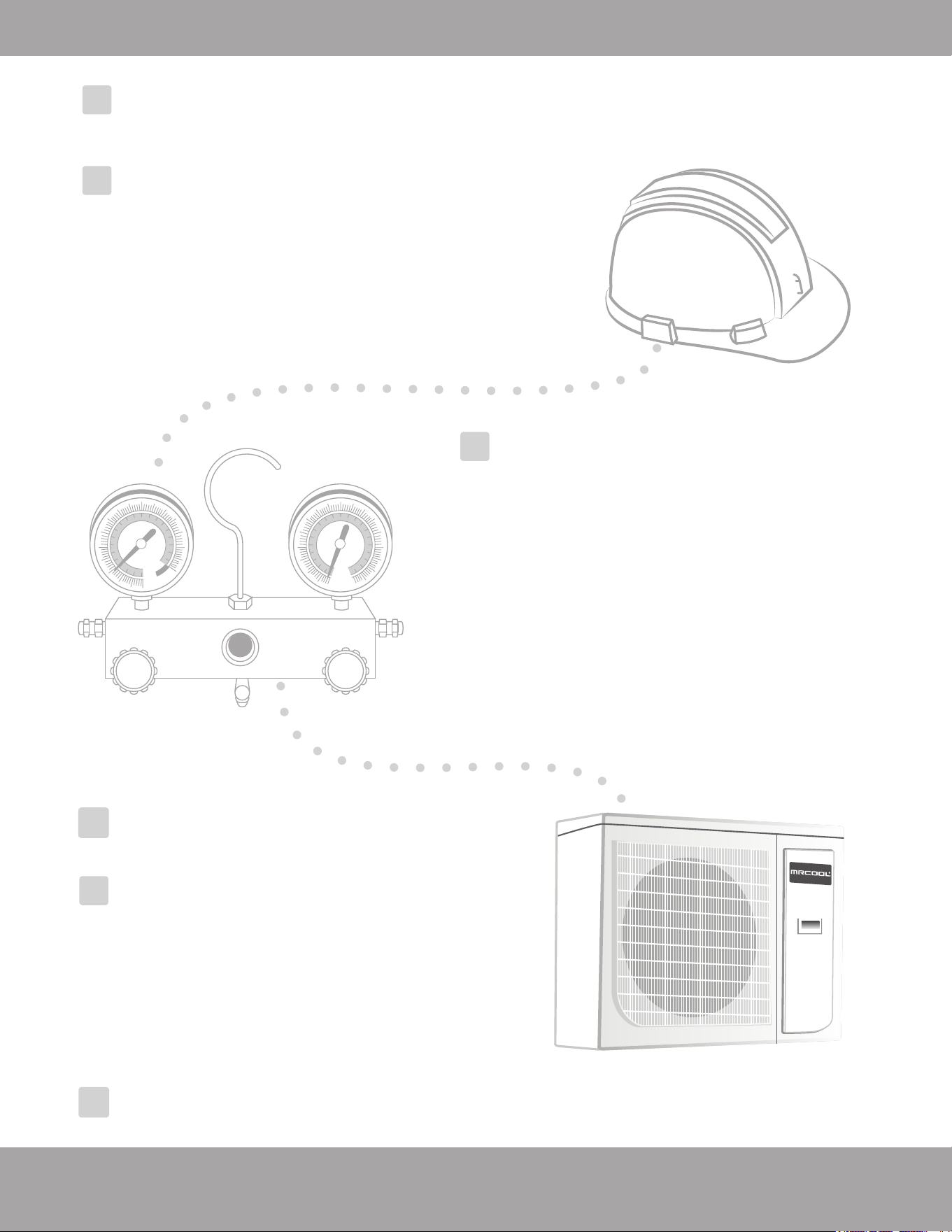
Wear safety glasses, protective clothing, and work gloves during installation. Also, have a fire
extinguisher available in case of an emergency.
Always use a quenching cloth for brazing operations.
This air-conditioning unit contains R-410A fluorinated gases.
The refrigerant gas may not have an odor, so this should not be considered a means of leak
detection.
Installation, service, maintenance, and repair of this unit must be performed by a certified technician.
Product un-installation and recycling must be performed by a certified technician.
If the system has a leak-detection system installed, it should be checked for leaks at least every 12
months.
Keep a record of all leak checks for the lifetime of the unit.
Page 4
Safety Precautions
mrcool.com
1.
2.
DO NOT install the unit within 3 feet (1 meter) of combustible materials if the unit is
equipped with an auxiliary electric heater.
DO NOT install the unit in a location that may be exposed to combustible gases. If
combustible gas accumulates around the unit, it could cause fire and/or an explosion.
DO NOT operate your air conditioner in a room where it could be exposed to excessive
amounts of water, such as a bathroom or laundry room. This could cause electrical
components to short circuit.
DO NOT put appendages or other objects into the air inlet or return grills.
DO NOT stop the appliance by directly cutting off the power. Turn off the unit first.
DO NOT install the appliance in areas with the following:
oil smoke or volatile liquid, as plastic parts may deteriorate, adversely affecting the
integrity and functionality of the appliance.
or corrosive gas; as this may corrode copper piping and welds, adversely affecting the
integrity and functionality of the appliance.
DO NOT force-dry the filter using an open flame or blowers, as this could damage it.
DO NOT operate the air conditioner with wet hands.
DO NOT wash or sprinkle water on the air conditioner, otherwise a malfunction and/or
electric shock could occur.
This appliance must be properly grounded during installation, or electrical shock could occur.
Install drainage piping according to the instructions in this manual. Improper drainage could
cause water damage to your home and property.
This appliance must be stored in a well ventilated area equal in size to the area specified for
operation. It must also be without a continuously operating open flame (ex. an operating gas
appliance) and ignition sources (ex. an operating electric heater).
Use proper measures to protect the outdoor unit from rodents and other small animals that could
damage electrical components, causing the unit to malfunction.
If wired control (i.e. a wall-mount thermostat) is to be used, it should be connected first before
powering up the unit, otherwise it may not function properly.
Only use a soft dry cloth or, as necessary, a slightly wet cloth with neutral detergent to clean the
casing of this appliance.
Before operating the unit under low temperature, connect it to power for 8 hours. If it is
deactivated for a short time, for example, one night, do not cut off the power (this is to protect the
compressor).
If the unit is to be installed in a small space, please adopt protective measures to prevent the
concentration of refrigerant from exceeding the allowable safety limit; excessive refrigerant
leakage could lead to an explosion.
When installing or re-installing the air conditioner, please keep the refrigerant circuit away from
substances other than the specified refrigerant, such as air. Any presence of foreign substances
will cause an abnormal pressure change or even an explosion, resulting in injury.
Please adopt safety protection measures before touching the refrigerant pipe; otherwise injury
could occur.
Please select the properly-sized copper piping according to the requirements for pipe thickness.
1.
2.
3.
4.
5.
6.
7.
8.
9.
10.
11.
.
.

Page 5
Safety Precautions
mrcool.com
To Our Customers;
Thank you for choosing a MRCOOL
®
home HVAC product. Please read this manual carefully before
installation and operation of the Universal
®
Series Cooling-Only Condenser to ensure correct use and
handling. In addition to the safety precautions in the previous section, please adhere to the following
guidelines and note our exceptions to liability.
This appliance can be used by children aged 8 years and older and persons with reduced physical,
sensory or mental capabilities, or lack of experience and knowledge if they have been given supervision
or instruction concerning use of the appliance and understand the hazards involved. Children should not
play with the appliance. Cleaning and user maintenance should not be performed by children.
To ensure product reliability, the unit may consume power under stand-by status to maintain normal
communication, and for preheating refrigerant and lubricant. If the unit will not be used for an extended
period, disconnect the power supply. Reconnect the power supply and preheat the unit prior to use.
Ensure you have selected the proper model for the operating environment. Improper selection may
impact operating performance.
This product has undergone strict inspection and operational testing before leaving the factory. In order
to avoid damage due to improper disassembly, which may impact the normal operation, please do not
disassemble the unit without the proper training and/or equipment.
For technical assistance, please contact MRCOOL
®
technical support, at (270) 366-0457.
If the product is malfunctioning and/or is inoperable please contact MRCOOL
®
technical support, at the
aforementioned number, as soon as possible and provide the following information:
a. Product Nameplate Contents (model number, cooling/heating capacity, product serial number,
factory date)
b. Nature of Malfunction (specify the circumstances before and after the error occurred)
All illustrations and information in the instruction manual are for reference only. In order to improve the
product , we will continuously assess and innovate. We retain the right to make necessary revisions to the
product from time to time. We reserve the right to revise the contents of this manual without notice.
If the supply cord is damaged, it must be replaced by MRCOOL
®
, a professional service agent, or a
similarly qualified person in order to avoid damage to the product.
MRCOOL
®
, LLC assumes no responsibility for personal injury, property loss or equipment damage caused
by improper installation and commissioning, unnecessary maintenance, or failure to follow relevant
federal and state regulations, industrial standards, and the requirements of this instruction manual.
MRCOOL
®
, LLC will bear no responsibilities for personal injury or property damage caused by the
following:
a. Improper use of the appliance
b. Altering, maintaining, or operating the product with non-approved equipment.
c. Altering, maintaining, or operating the product outside of the guidelines of this manual.
d. Defects caused by corrosive gas.
e. Defects caused by shipping damage.
f. Failure to abide by this instruction manual or government regulations.
g. Products made by other manufacturers
h. Natural disasters, improper installation environment, or force majeure.
1
Appliance Overview
1.
2.
3.
4.
5.
6.
7.
8.
9.
10.
Page 6
mrcool.com
Appliance Overview
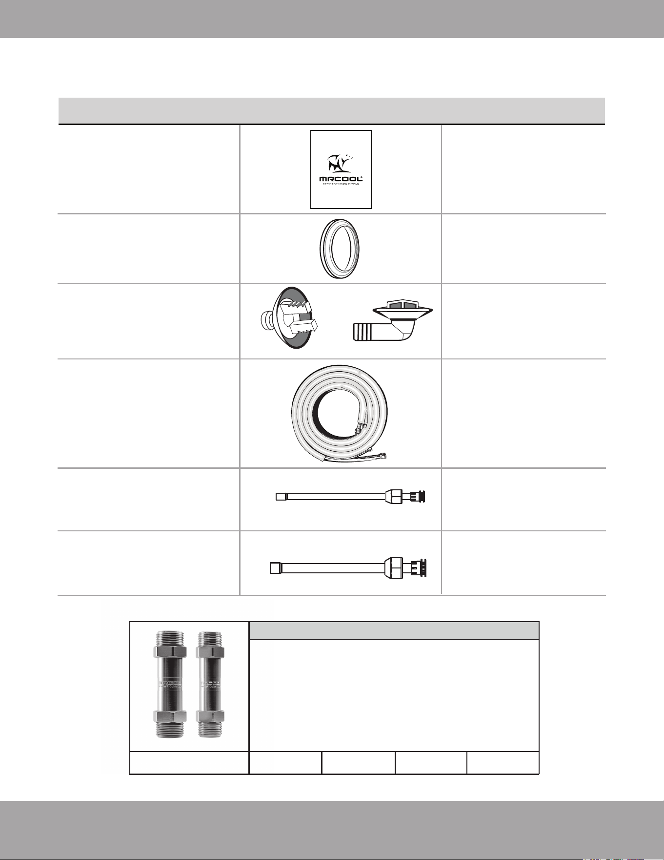
Unless otherwise stated (as “OPTIONAL”) the air conditioning system includes the following
accessories. Use all of the installation parts and accessories to install the air conditioner. Improper
installation may result in water leakage, electrical shock, fire, and/or equipment failure.
3
1
1
Owner’s Manual
Drain Plug
Drainage Connector
PART LOOKS LIKE... QUANTITY
Owner’s Manual
Universal®™ Series
Central Heating & Air Conditioning
1
1
Liquid Side Stub Kit
Gas Side Stub Kit
To connect the unit
with the liquid pipe
To plug the unused
drain hole
To connect with the
PVC drain pipe
To connect the unit
with the gas pipe
or
OPTIONAL
No-Vac
®
Quick Connect
®
Line Set*
Gas / Liquid
Pipe Assembly
1
Fig. 1.1
Additional Line Sets & Coupler Kit
If you find the standard size NO-VAC
®
QUICK CONNECT
®
LINE SET length is not sufficient for your application,
additional line sets are available for purchase. You will also
need a NO-VAC
®
COUPLER kit (pictured), which allows line
sets to be connected together to increase the length. The
coupler kit is installed and checked for leaks by following the
same steps described in this manual for connecting the line
set to the indoor air handler (Refer to the NO-VAC
®
QUICK
CONNECT
®
Line Set section on pg. 24 for these steps).
NO-VAC
®
QUICK CONNECT
®
LINE SET Lengths Available
15 FT
25 FT
35 FT
50 FT
*Pat. https://mrcool.com/mrcool-patents/
Page 7
mrcool.com
Appliance Overview
COOLING HEATING
Operating Range
39.2°F(4°C) ~ 118.4°F (48°C) N/A
Outdoor Temperature
Fig. 1.2
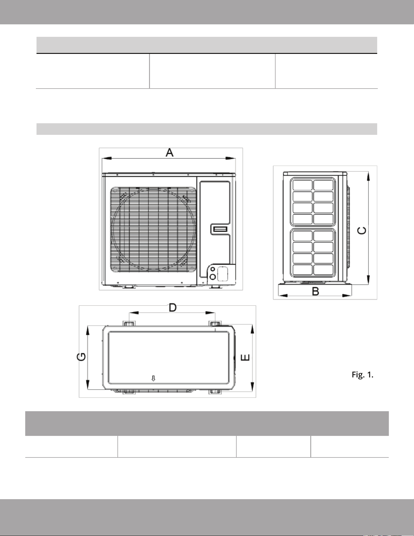
Unit Dimensions of 2-3 Ton Condenser
MDUCO18024036
Outdoor Unit DimensionsModel
Width (A) x Height (C) x Depth (G)
Mounting Dimensions
Width (A / D) Depth (B / E)
37 in x 32-1/4 in x 18-1/8 in.
940 mm x 820 mm x 460 mm
37 in / 24 in
940 mm / 610 mm
20-7/8 in / 19-1/8 in
530 mm / 486 mm
MDUCO18024036
Page 8
mrcool.com
Appliance Overview
COOLING HEATING
Operating Range
39.2°F(4°C) ~ 118.4°F (48°C) N/A
Outdoor Temperature
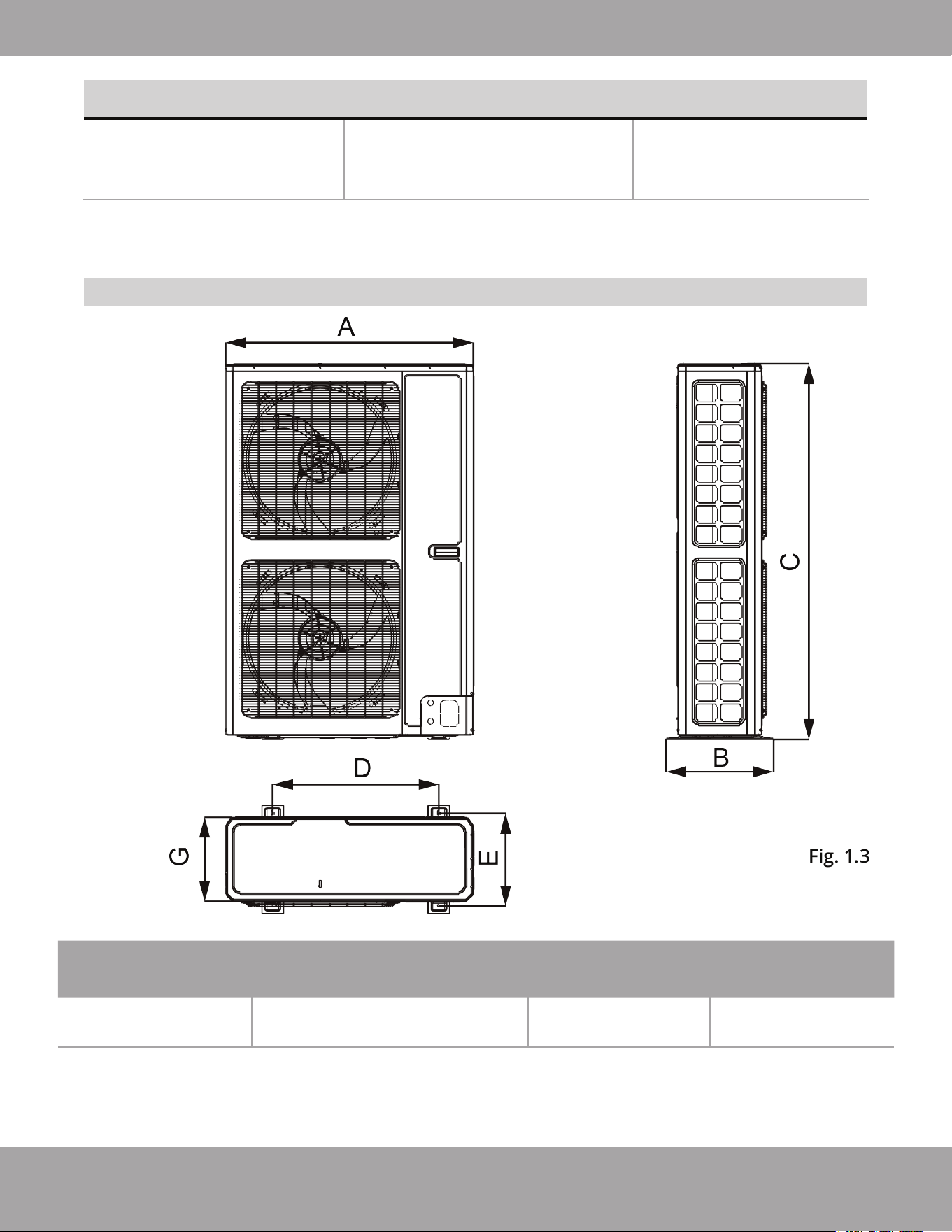
Fig. 1.3
Unit Dimensions of 4-5 Ton Condenser
MDUCO18048060
Outdoor Unit DimensionsModel
Width (A) x Height (C) x Depth (G)
Mounting Dimensions
Width (A / D) Depth (B / E)
37 in x 56-3/8 in x 12-5/8 in
940 mm x 1430 mm x 320 mm
37 in / 24-7/8 in
940 mm / 632 mm
16-1/8 in / 13-7/8 in
410 mm / 353 mm
MDUCO18048060

Page 9
mrcool.com
WARNING
DO NOT install the unit where combustible gas leakage may occur.
The unit must be installed in a location strong enough to support the weight of the unit and fixed
securely, to avoid toppling.
Install the appliance in a location where there is an incline of less than 5°.
The outdoor unit does not have a TXV (thermal expansion valve), please make sure there is a
throttling valve in the indoor unit (on the air handler or “A” coil).
1.
2.
3.
2
Unit Installation
Installation Location
Select an installation location for the outdoor unit pursuant to the following conditions:
Noise and airflow produced by the outdoor unit will not disturb neighbors.
The location is away from animals and plants. If not, please add safety fences to protect the unit.
The area is well ventilated with no nearby obstacles that could obstruct airflow.
The location is able to support the weight and withstand the operating vibration of the unit.
Installation is able to be performed safely.
The location area is free of combustible or corrosive gas, and oil smoke.
Unit is able to be shielded from strong wind. Strong wind may affect the outdoor fan and lead to
insufficient airflow volume, thus affecting performance.
Unit is away from objects which can generate or amplify noise during operation.
Condensate can be safely drained from the unit.
1.
2.
3.
4.
5.
6.
7.
1. The Conventional Weld Line Set Installation
Instructions can be found on pages 15 - 23
OR
View complete install video by scanning this QR code
2.
No-Vac
®
Quick Connect
®
Line Set*
Installation
Instructions can be found on page 24
OR
View complete install video by scanning this QR code
The Universal™ Series has 2 installation methods
MRCOOL
®
Preferred Method
8.
9.
*Pat. https://mrcool.com/mrcool-patents/
Page 10
mrcool.com
Unit Installation
A
C
B
D
a
b
d
c
e
H
d
H
b
H
E
A ~ E
inches (in) millimeters (mm)
a b c d e
B —
≥ 3.94 in
100 mm
A,B,C, —
B,E —
A,B,C,E —
D —
D,E —
B,D
B,D,E
Prohibited
Prohibited
Hb Hd H
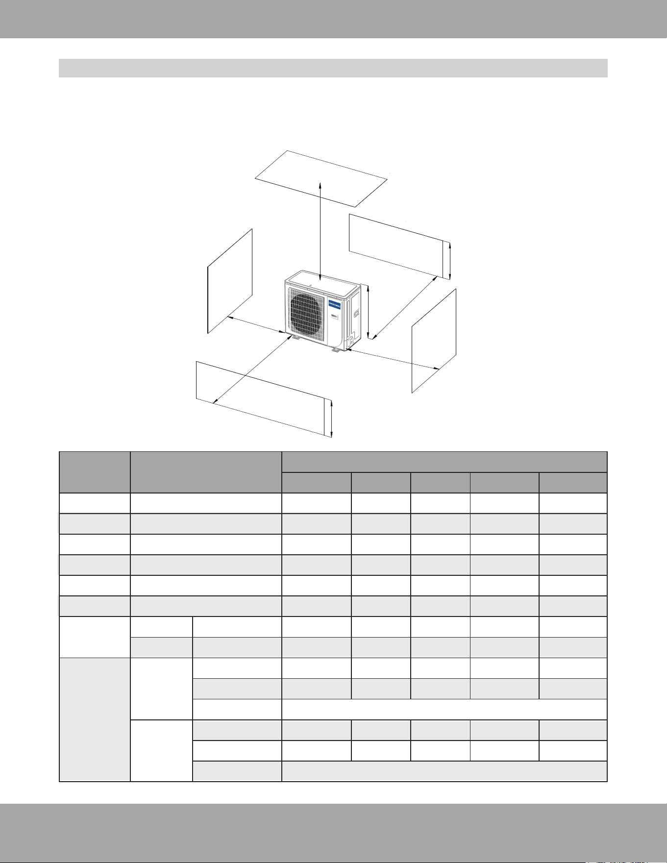
For best performance of the outdoor unit, make sure its installation space conforms to the
following installation dimensions...
For installation of a single condenser refer to Fig 2.1 below:
Fig. 2.1
≥ 3.94 in
100 mm
≥ 3.94 in
100 mm
≥ 3.94 in
100 mm
≥ 3.94 in
100 mm
≥ 3.94 in
100 mm
≥ 3.94 in
100 mm
≥ 9.84 in
250 mm
≥ 9.84 in
250 mm
≥ 11.81 in
300 mm
≥ 11.81 in
300 mm
≥ 39.37 in
1000 mm
≥ 39.37 in
1000 mm
≥ 39.37 in
1000 mm
≥ 39.37 in
1000 mm
≥ 39.37 in
1000 mm
≥ 39.37 in
1000 mm
≥ 39.37 in
1000 mm
≥ 39.37 in
1000 mm
≥ 39.37 in
1000 mm
≥ 39.37 in
1000 mm
≥ 78.74 in
2000 mm
≥ 78.74 in
2000 mm
≥ 78.74 in
2000 mm
≥ 78.74 in
2000 mm
≥ 7.87 in
200 mm
≥ 39.37 in
1000 mm
≥ 5.9 in
150 mm
≥ 5.9 in
150 mm
Hb < Hd
Hb >Hd
Hb < Hd
Hb > Hd
Hd > H
H
d < H
1/2H < Hb ≤ H
Hb ≤ 1/2H
Hb > H
H
d ≤ 1/2H
1/2H < Hd ≤ H
Hd > H
Installation Location
Page 11
mrcool.com
Unit Installation
Fig. 2.2
A ~ E
inches (in) millimeters (mm)
a b c d e
A,B,C, —
—
A,B,C,E
—
D
—
D,E
B,D
B,D,E
Prohibited
Prohibited
Hb Hd H
≥ 9.84 in
250 mm
≥ 11.81 in
300 mm
≥ 11.81 in
300 mm
≥ 11.81 in
300 mm
≥ 11.81 in
300 mm
≥ 11.81 in
300 mm
≥ 9.84 in
250 mm
≥ 11.81 in
300 mm
≥ 11.81 in
300 mm
≥ 39.37 in
1000 mm
≥ 11.81 in
300 mm
≥ 11.81 in
300 mm
≥ 39.37 in
1000 mm
≥ 39.37 in
1000 mm
≥ 39.37 in
1000 mm
≥ 39.37 in
1000 mm
≥ 39.37 in
1000 mm
≥ 39.37 in
1000 mm
≥ 39.37 in
1000 mm
≥ 78.74 in
2000 mm
≥ 78.74 in
2000 mm
≥ 78.74 in
2000 mm
≥ 78.74 in
2000 mm
≥ 78.74 in
2000 mm
≥ 98.43 in
2500 mm
≥ 98.43 in
2500 mm
≥ 98.43 in
2500 mm
≥ 98.43 in
2500 mm
Hb < Hd
Hb >Hd
Hb < Hd
Hb > Hd
Hd > H
H
d < H
1/2H < Hb ≤ H
Hb ≤ 1/2H
Hb > H
H
d ≤ 1/2H
Hd ≤ 1/2H
1/2H < Hd ≤ H
Hd > H
A
B
C
D
E
a
b
c
d
H
d
Hb
H
e
≥ 15.75 in
400 mm
≥ 15.75 in
400 mm
Installation Location
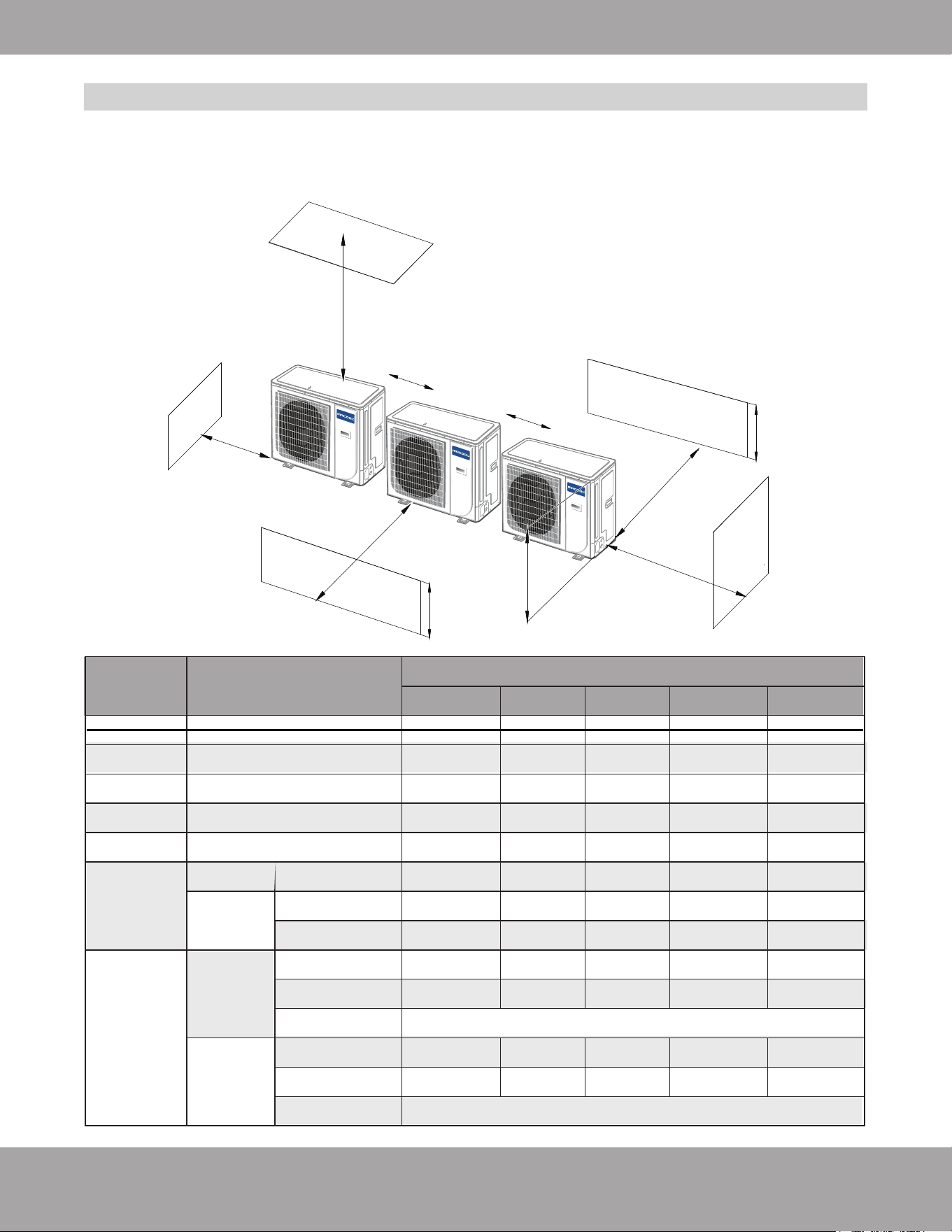
For best performance of the outdoor unit, make sure its installation space conforms to the
following installation dimensions...
For installation of multiple condensers side by side refer to Fig 2.2 below:
Page 12
mrcool.com
Unit Installation
inches (in) millimeters (mm)
Prohibited
1/2H < Hb ≤ H
Hb ≤ 1/2H
Hb > H
Hb H
Hb
H
B
≥ 15.75 in
400 mm
≥ 157.5 in
4000 mm
≥ 15.75 in
400 mm
≥ 23.62 in
600 mm
≥ 7.87”
200mm
≥ 7.874 in
2000 mm
≥ 7.874 in
2000 mm
≥ 177.17 in
4500 mm
≥ 7.87”
200mm
≥ 7.87 in
200 mm
≥ 7.87”
200mm
≥ 7.87 in
200 mm
Fig. 2.3
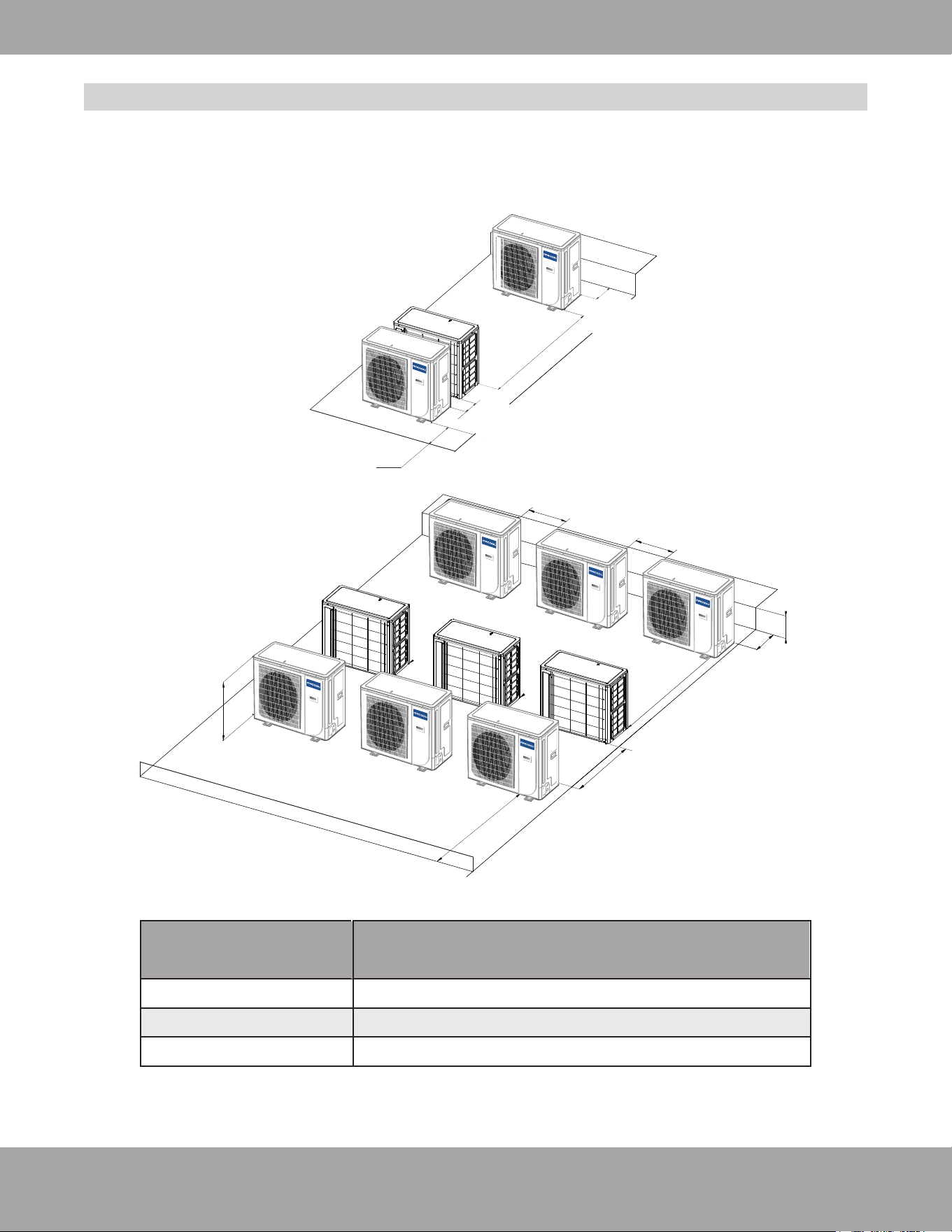
For best performance of the outdoor unit, make sure its installation space conforms to the
following installation dimensions...
For installation of multiple condensers in rows refer to Fig 2.3 below:
Installation Location
b ≥ 9.84 in (250 mm)
b ≥ 11.81 in (300 mm)
Page 13
mrcool.com
Unit Installation
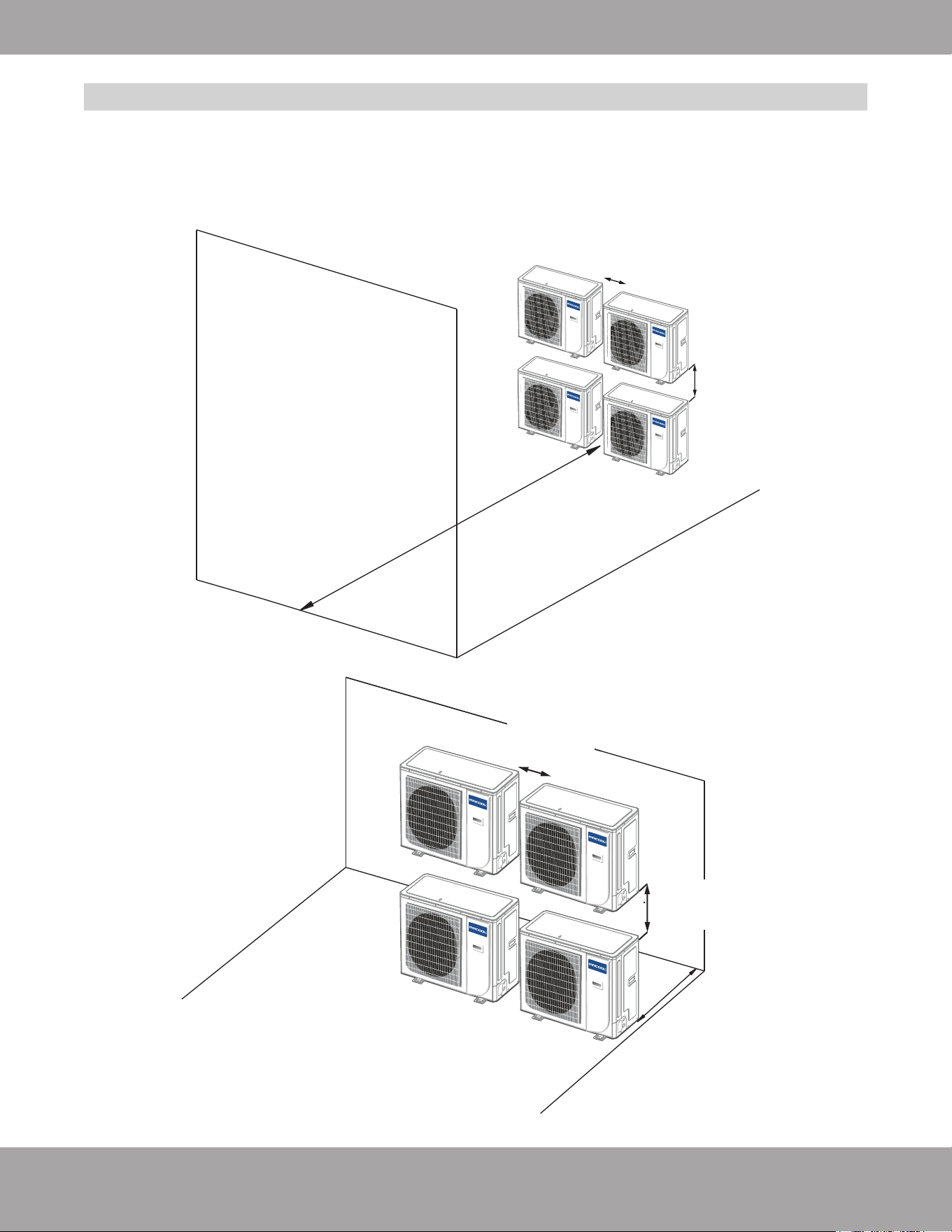
For best performance of the outdoor unit, make sure its installation space conforms to the
following installation dimensions...
For installation of multiple condensers on a vertical face refer to Fig 2.4 below:
≥ 7.874 in
2000 mm
WALL
≥ 15.75 in
400 mm
≥ 15.75”
400mm
≥ 19.69”
500mm
≥ 19.69 in
500 mm
≥ 11.81 in
300 mm
≥ 19.69 in
500 mm
≥ 15.75 in
400 mm
Fig. 2.4
Installation Location
Page 14
mrcool.com
Unit Installation
1.
2.
3.
4.
If the outdoor unit is installed on a solid surface such as concrete, use M10 screw bolts and nuts to
secure the unit. Make sure the unit stands erect and level.
If the unit vibrates and generates noise, add rubber cushions between the unit’s feet and the
installation surface.
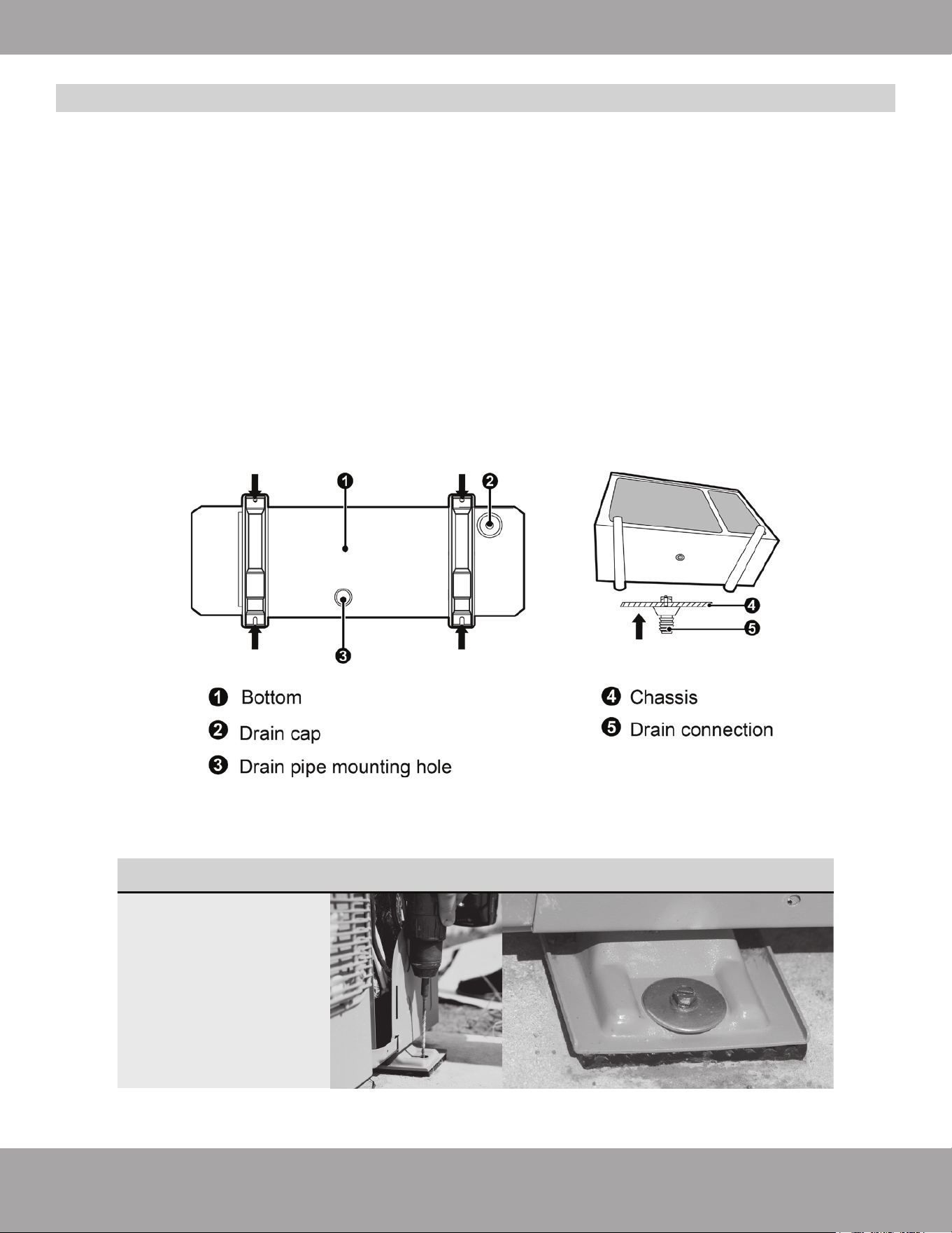
When the outdoor unit is in heating or defrosting mode, it must drain water. When installing the drain
pipe, plug the accompanied drainage connector to the drainage hole on the chassis of the outdoor unit.
Then, connect the drain hose to the drainage connector. If the drainage connector is used, the outdoor
unit should be at least 4 in (10 cm) from the ground.
Plugs and drainage connector are not recommended if there is an electrical heater on the chassis.
Refer to Fig. 2.5 for details.
Fig. 2.5
Outdoor Unit Installation
The outdoor condenser
can also be mounted to
concrete with the use of
masonry anchors. Be
sure to drill an
appropriate sized pilot
hole before attempting
to screw the anchor into
the concrete.
NOTE
Page 15
mrcool.com
Unit Installation
Outdoor Unit Model
Liquid Pipe Gas Pipe
Size of Fitting Pipe
Maximum
Pipe Length
Maximum Drop
between indoor and
outdoor units
3/8 in 3/4 in
98.4 ft
(30 m)
49.2 ft
(15 m)
MDUCO18024036
MDUCO18048060
INSTALLATION METHOD
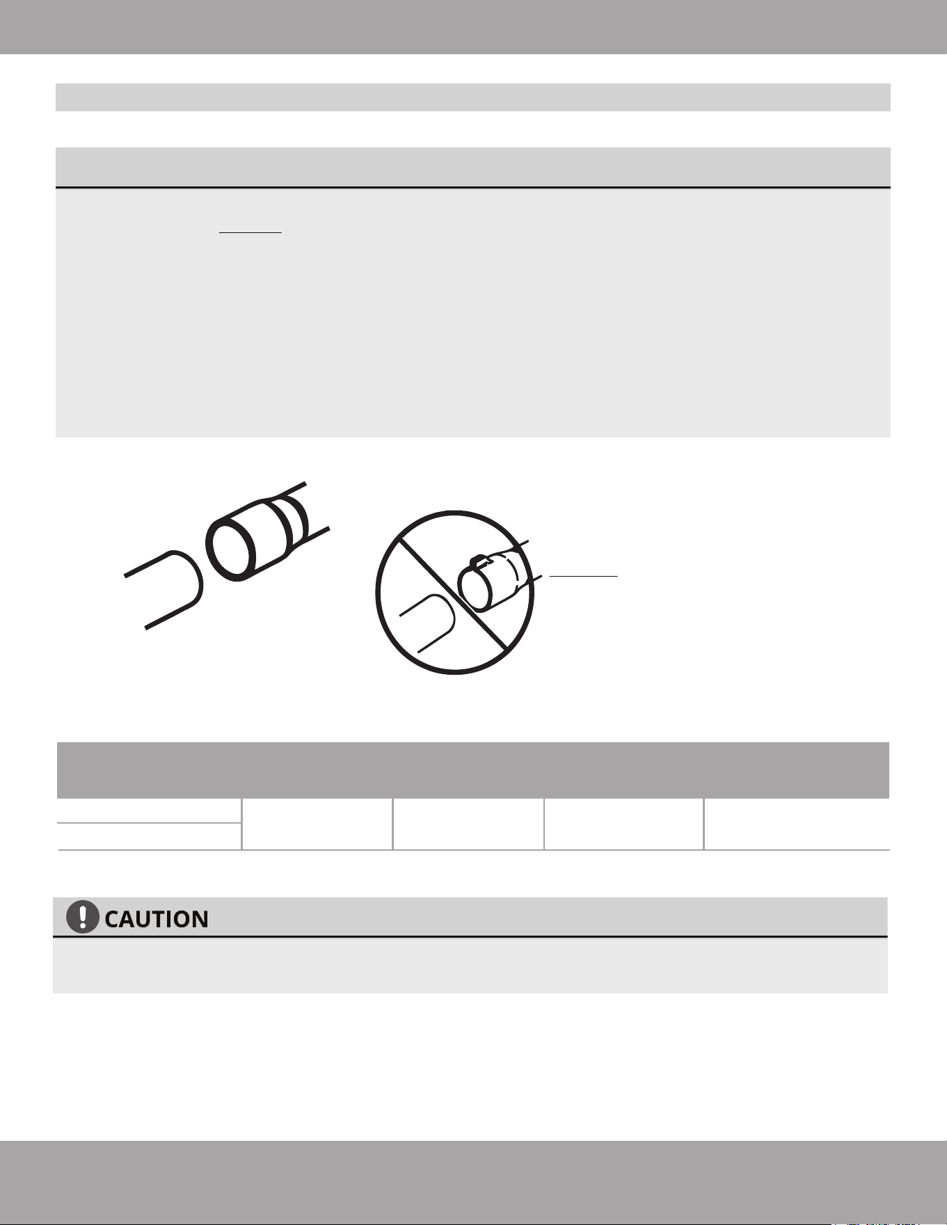
Connect the refrigerant lines to the unit first. When bending a refrigerant pipe, be careful not to kink
or crimp the pipe. DO NOT over-tighten the flare nut, otherwise leakage may occur. The outside of
the refrigerant pipe should have a layer of insulating cotton to protect it from mechanical damage
during installation, maintenance, and transportation.
Refrigerant lines should adopt water-proof insulating material. The pipe wall thickness should be
0.5-1.0 mm and able to withstand 6.0 MPa. Excessive length of the refrigerant lines will negatively
affect cooling and heating performance. Attempt to minimize refrigerant line length when possible.
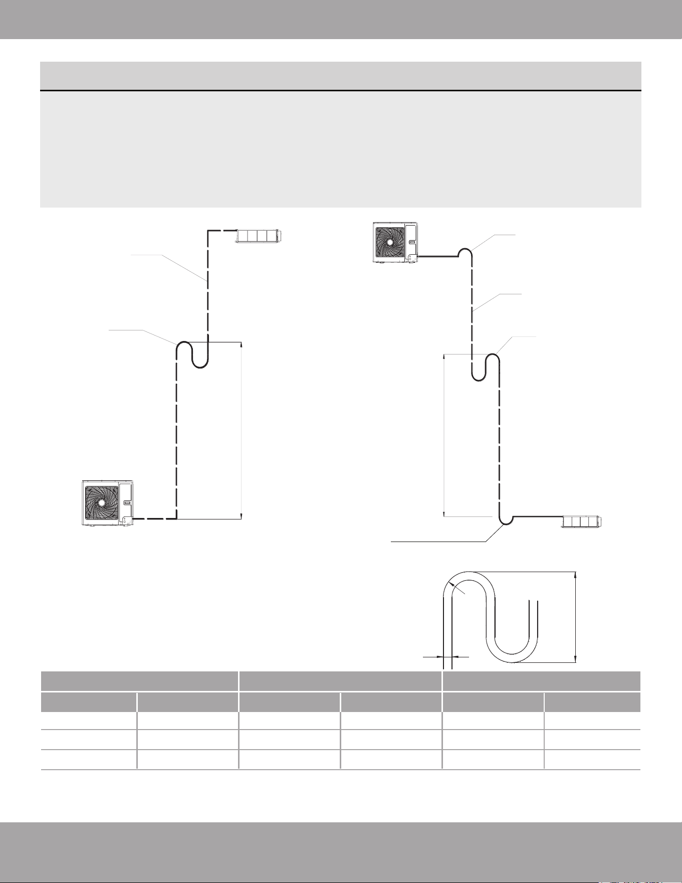
When the drop between indoor and outdoor units is larger than 32 ft (10 m), an oil return bend should
be added every 19.69 ft (6 m).
Be extremely careful not to dent or damage the piping while bending them away from the unit. Any
dents in the piping will affect the unit’s performance.
LINE SET SIZE
MUST MATCH
SERVICE VALVE
CONNECTION
DO NOT CRIMP SERVICE VALVE
CONNECTOR IF PIPE IS
SMALLER THAN CONNECTOR
Conventional Line Set Installation
For installation with a No-Vac
®
Quick Connect
®
Line Set, refer to the next section starting on page 24
Page 16
mrcool.com
Unit Installation
Fig. 2.6
Fig. 2.7
Install an oil
return bend
every 20 ft (6 m)
Oil return bend
System gas pipe
Outdoor unit
Indoor unit
Outdoor unit
Non-return bend
System gas pipe
Oil return bend
Indoor unit
Install an oil
return bend
every 20 ft (6 m)
OIL RETURN BENDS
Add an oil return bend as described below:
If the outdoor unit is installed beneath the indoor unit, install an oil return bend every 20 ft (6 m).
A non-return bend is not needed in this configuration. Please refer to Fig. 2.6 below:
If the outdoor unit is installed above the indoor unit, install an oil return bend every 20 ft (6 m). It
is also necessary to add a non-return bend at the lowest and highest position of the vertical pipe, as
shown below in Fig. 2.7:
Use the following dimensions in Fig. 2.8 to form the oil return bend(s):
C
B
A
A (Pipe Diameter)
B C
Ф12
Ф1/2
≥26
≤150
Ф16
Ф5/8
≥33 ≤150
Ф19
Ф3/4
≥34
≥1
≥1.3
≥1.34
≥5.91
≥5.91
≥5.91
≤150
Fig. 2.8
mmInches mmInches mmInches
•
•
Non-return bend
Page 17
mrcool.com
Unit Installation
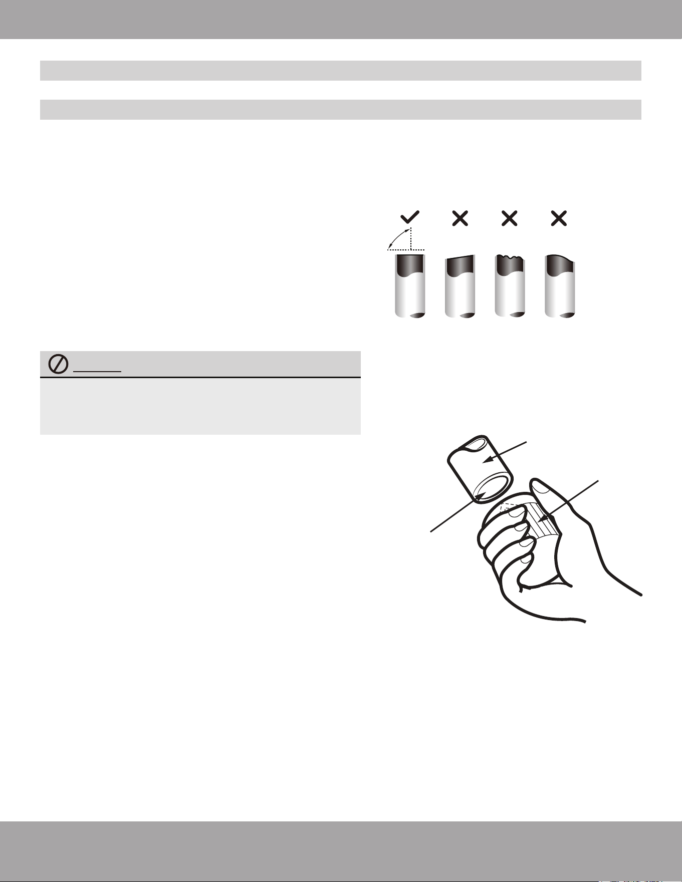
Oblique Rough Warped
90°
Fig. 2.9
Conventional Line Set Installation
Pipe Cutting
Step 1: Cut Pipe
1. When preparing refrigerant pipes, take extra care to cut
and flare them properly. This will help to ensure the piping
has an airtight seal, which can affect operation efficiency
and the need for future maintenance.
2. Measure the distance between the indoor and outdoor
units.
3. Using a pipe cutter, cut the pipe a little longer than
the measured distance.
4. Make sure that the pipe is cut at a perfect 90° angle.
Refer to Fig. 2.9 for cut examples.
Pipe
Reamer
Point down
Fig. 2.10
Be extra careful not to damage, dent, or deform
the pipe while cutting. This will drastically reduce
the heating efficiency of the unit.
Step 2: Remove burrs
Burrs can affect the airtight seal of the refrigerant piping
connection. They must be completely removed.
1. Hold the pipe at a downward angle to prevent burrs
from falling into the pipe.
2. Using a reamer or deburring tool, remove all burrs from
the cut section of the pipe. Refer to Fig. 2.10
3. After removing burrs from the cut pipe, seal the ends
with PVC tape to prevent foreign materials from entering
the pipe.
For installation with a No-Vac
®
Quick Connect
®
Line Set, refer to the next section starting on page 24
DO NOT DEFORM PIPE WHILE CUTTING
Page 18
mrcool.com
Unit Installation
Flare nut
Copper pipe
Fig. 2.11
Fig. 2.12
Fig. 2.14
PIPING EXTENSION BEYOND FLARE FORM
Flare form
Pipe
A
A = ~1/16 in (1.6 mm)
Fig. 2.13
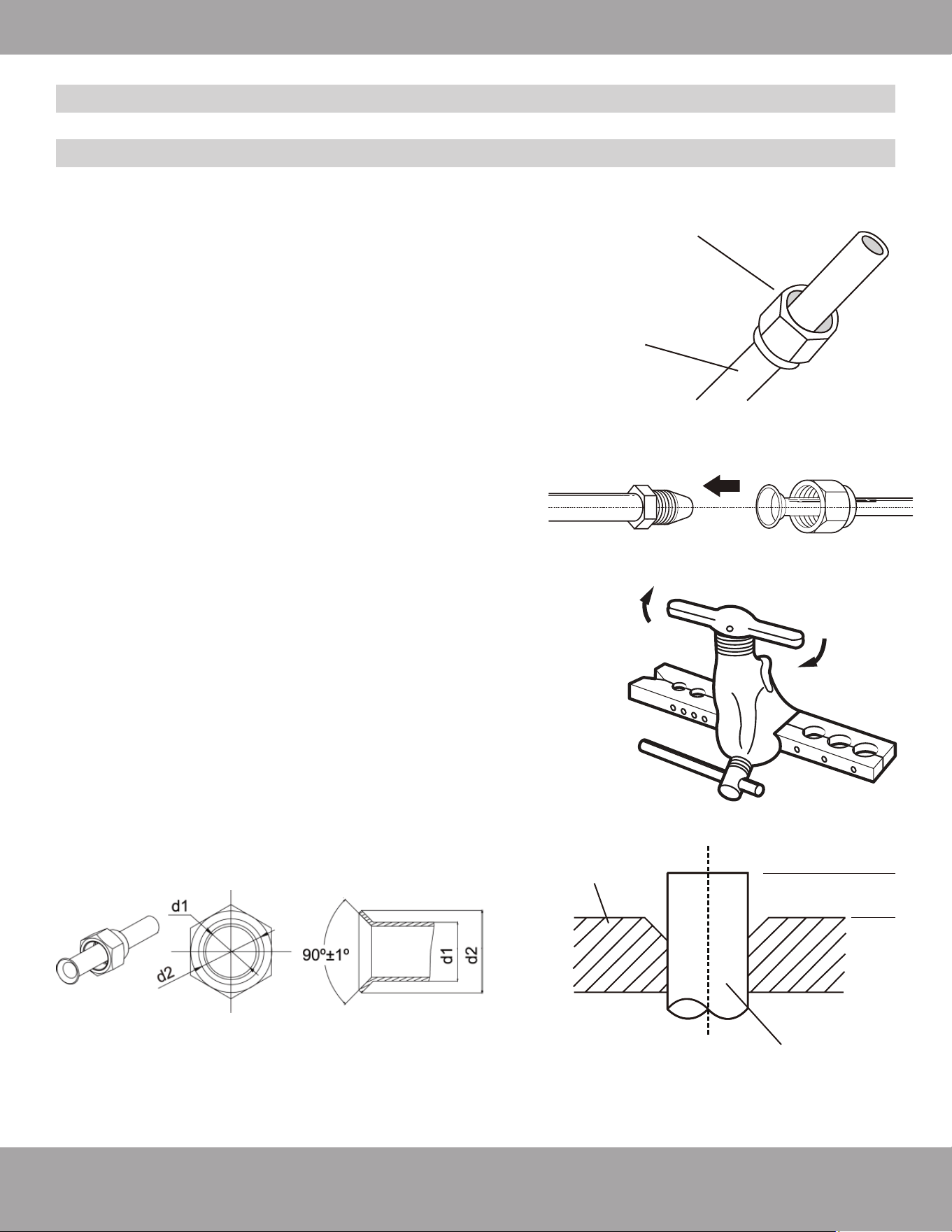
Step 3: Flare pipe ends
Proper flaring is essential to achieve an airtight seal.
1. Sheath the pipe with insulating material as necessary
2. Remove the cut-off valve of the outdoor unit and take out
the flare nut from the bag of indoor unit accessories. Fit
the flare nut on the pipe. See Fig 2.11.
3. Make sure it is facing in the right direction, because you
cannot remove the nut or change its direction once the
pipe has been flared. See Fig. 2.12.
4. Remove PVC tape from the end of the pipe when ready to
perform flaring work.
5. Clamp flare form on the end of the pipe. The end of the
pipe should extend ~ 1/16 in (1.6 mm) beyond the edge of
the flare form, as shown in Fig. 2.14.
6.
Place flaring tool onto the form, as shown in Fig. 2.13.
7
. Turn the handle of the flaring tool clockwise until the pipe
is fully flared, as shown in Fig. 2.13.
8.
Remove the flaring tool and flare form, then inspect the
end of the pipe for cracks and even flaring.
Conventional Line Set Installation
Pipe Flaring
For installation with a No-Vac
®
Quick Connect
®
Line Set, refer to the next section starting on page 24
Page 19
mrcool.com
Unit Installation
1. Use your hands to bend the pipes. Work carefully not to collapse the pipes during bending.
2. If the pipe is repeatedly bent or extended, it will become hard and difficult to manipulate. Avoid bending
or extending the pipe more than 3 times.
DO NOT bend the pipe excessively, otherwise it will break.
DO NOT bend the pipes at an angle greater than 90°.
Refer to Fig. 2.15
Conventional Line Set Installation
Pipe Bending
3. As shown in Fig. 2.16, use a sharp cutter to cut the pipe
insulation and bend the pipe after it is exposed. After
bending the pipe to the desired angle, place the insulation
back on the pipe and secure it with adhesive tape.
Fig. 2.16
Pipe
Insulation
Pipe
Cutter
Cut line
Fig. 2.15
Extend the pipe by unwinding it
≥4 in (10 cm)
Radius
MINIMUM BEND RADIUS
When bending connective refrigerant
piping, the minimum bending radius is
10 cm. Refer to Fig. 2.15
For installation with a No-Vac
®
Quick Connect
®
Line Set, refer to the next section starting on page 24

Replacement Condenser Only
Conventional Line Set Installation
Unit Installation
mrcool.com
Page 20
Existing Air Handler
Accessory copper
90 pipe Q+y*2
Purge with
Nitrogen
Weld joint
Purge with
Nitrogen
MRCOOL Universal Series DC Inverter
MRCOOL Universal Series
Must open stop
valves after pulling
vacuum and before
powering on
WELD Type Complete Unit Replacement
Weld joint
Weld joint
Air Handler
DC Inverter
Open stop valves
with allen wrench
only after nishing
line set connections
and before
powering on the
unit
must have 410
TXV Biow valve
Must install lter drier biow
with this installation type
Must install lter drier biow
with this installation type
Must Purge with Nitrogen
before brazing joints
Must Purge with Nitrogen
before brazing joints
Fig. 2.17
Fig. 2.18
IMPORTANT
In order to prevent the
refrigerant piping from
sweating, they can be
insulated with
closed-cell insulation
foam for refrigerant
line sets which is
readily available.
IMPORTANT
The existing air handler in
the house must be a 410
air handler and use a 410
TXV Biflow Valve
Page 21
mrcool.com
Unit Installation
Pipe diameter (in. | mm) Tightening torque ft/lbs (N·m)
Ф1/4 in | Ф6.4 mm
Ф3/8 in | Ф8.3 mm
Ф1/2 in | Ф12.7 mm
Ф5/8 in | Ф15.9 mm
Ф3/4 in | Ф19 mm
Ф7/8 in | Ф22.2 mm
11-22 ft/lb (15-30 Nm)
26-29 ft/lb (35-40 Nm)
33-37 ft/lb (45-50 Nm)
44-48 ft/lb (60-65 Nm)
52-55 ft/lb (70-75 Nm)
59-63 ft/lb (80-85 Nm)
DO NOT USE EXCESSIVE TORQUE
Excessive force can break the nut or damage
the refrigerant piping. You must not exceed
torque requirements shown in the table.
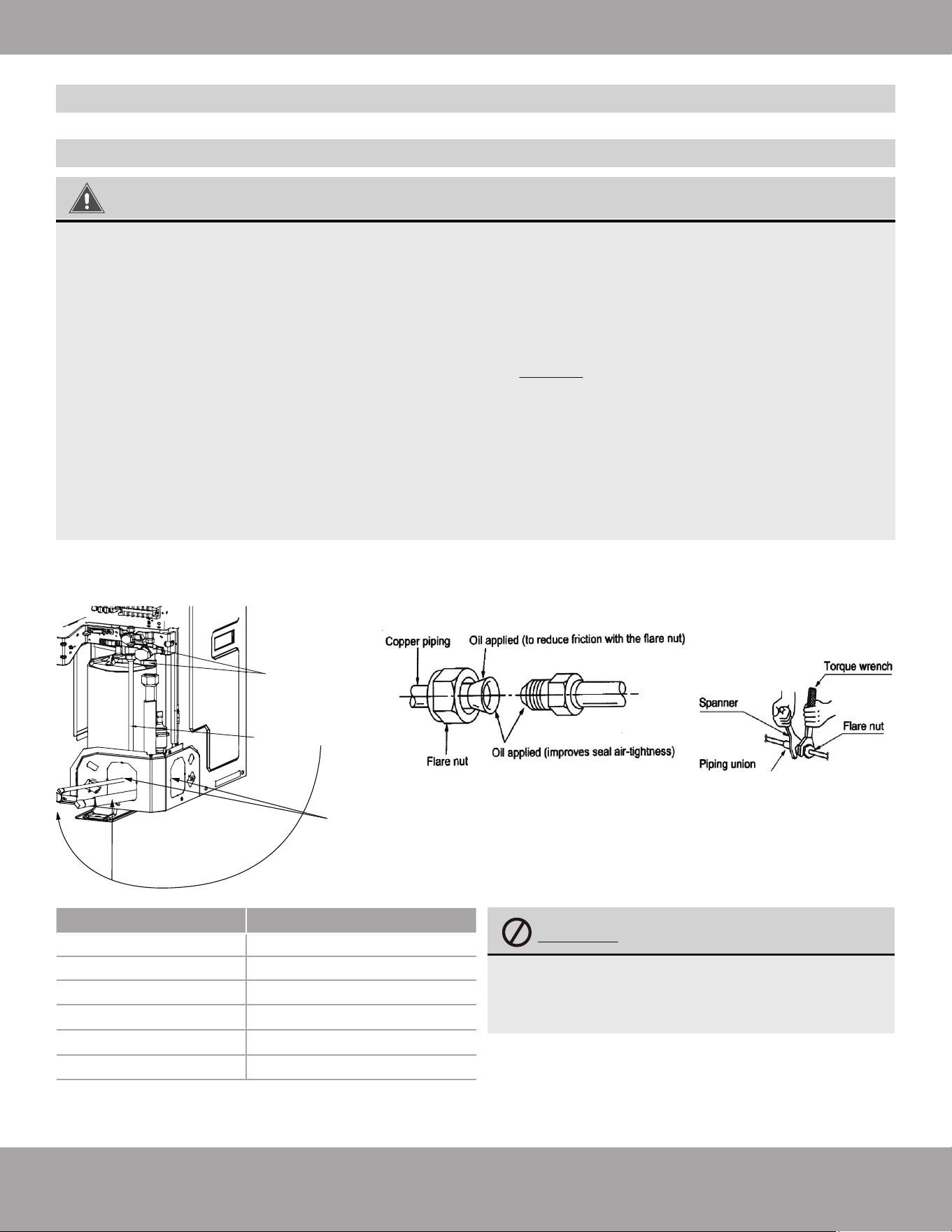
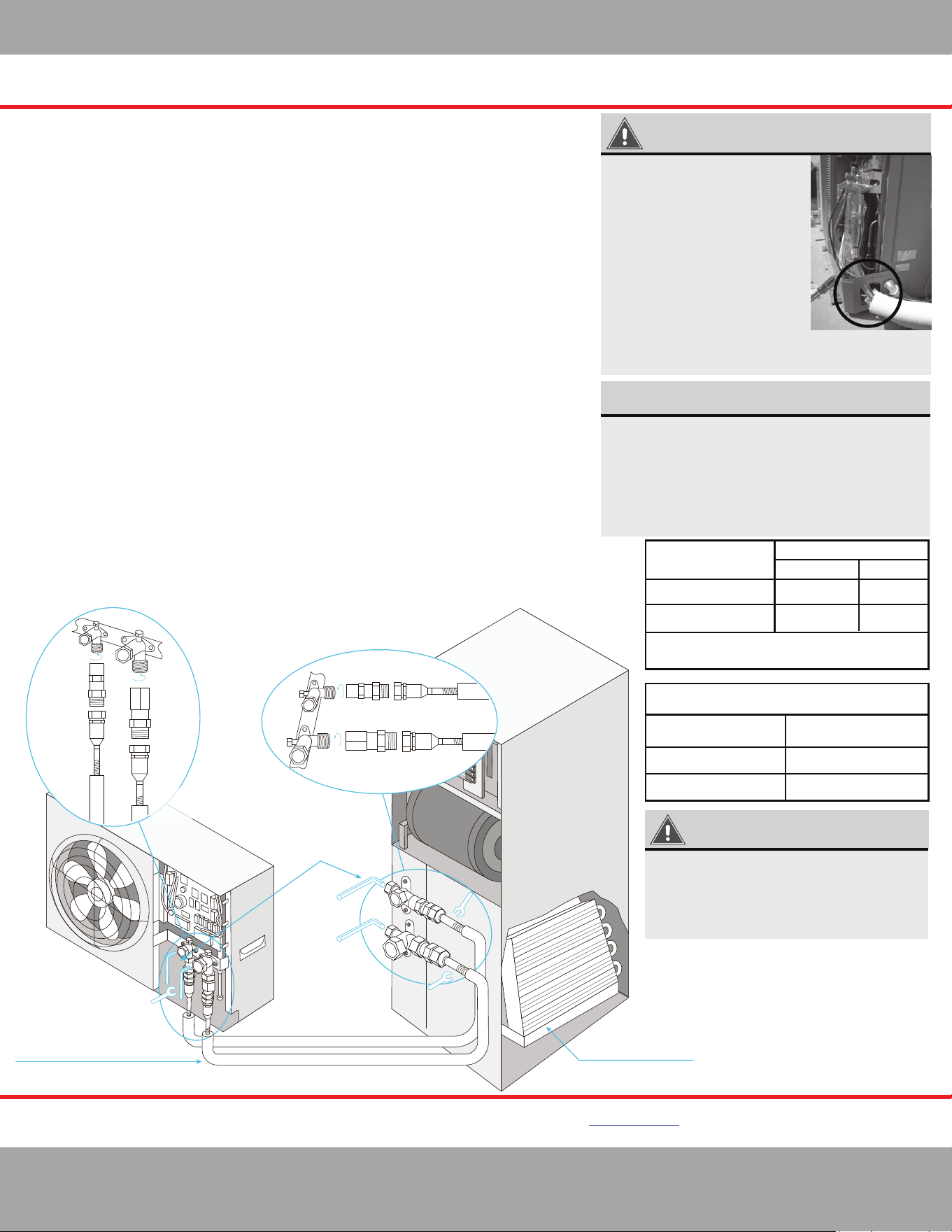
1.
Screw the flare nut of the flared connecting pipe onto the outdoor unit valve. Refer to Fig. 2.19A & Fig.
2.19B, using the torque values in the table below.
2. On Model MDUOC18024036 & MDUOC18048060 plug the knockout
holes shown in Fig. 2.19A with material such as neoprene to prevent
small animals and debris from entering the unit.
Fig. 2.19B
Fig. 2.19A
Refrigerant Line Set
Connection Pipes
Cut Off Valve
Knockout Holes
WARNING
Connect the pipe to the unit. Follow all instructions below. Use both a spanner and torque a wrench.
When connecting the tapered flare nut, first apply Polyolester oil (POE oil) on its inner and outer
surface and then screw the flare nut by hand 3 or 4 threads to ensure it does become crooked.
Be sure to connect gas pipe after the liquid pipe is connected.
Confirm the tightening torque by referring to the table below. Then tighten the flare nut to the
specified torque using a torque wrench and spanner. DO NOT over-tighten the flare nut. If the
flare nut is overtightened, it may be damaged and cause leakage.
Keep pipe connection joints exposed to perform the leak test (refer to Post Installation Checks
section of this manual).
If there are no leaks, then apply thermal insulation to the gas piping. Wind sponge around the joint
of the gas pipe and heat insulation sheath on the gas collecting pipe.
Insulation for the liquid piping is optional.
1.
2.
3.
4.
5.
6.
7.
Conventional Line Set Installation
Pipe Connection
For installation with a No-Vac
®
Quick Connect
®
Line Set, refer to the next section starting on page 24

Page 22
mrcool.com
Unit Installation
Conventional Line Set Installation
Vacuum Lines
WARNING
• Make sure the outlet of the vacuum pump is away from any potential source of fire and is well
ventilated.
• Before vacuum pumping, make sure the unit cut-off valves are closed.
• When vacuum pumping, both the liquid pipe and the gas pipe must be pumped.
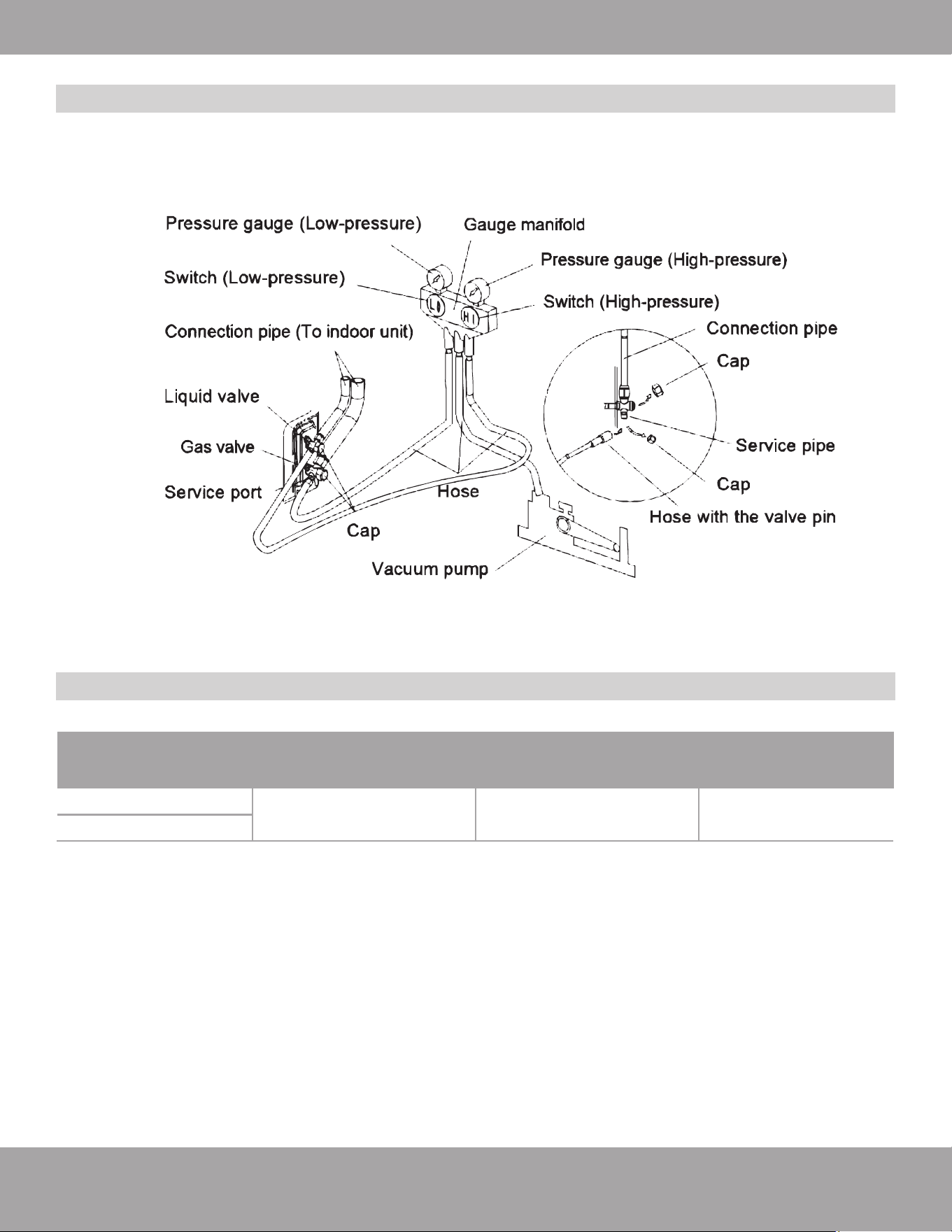
1. Remove the caps on the liquid valve, gas valve, and also the service port.
2. Connect the hose at the low pressure and high pressure sides of the manifold valve assembly to the
service port of the unit’s gas and liquid valve. Meanwhile, the gas and liquid valves should be kept closed
to avoid a refrigerant leak.
3. Connect the hose used for evacuation hose to the vacuum pump.
4. Open the switches on the lower pressure side and high pressure side of the manifold valve assembly at
the same time and start the vacuum pump.
5. The evacuation duration typically depends on the unit capacity: for Model MDUCO18024036 time is
generally 30 minutes, for model MDUCO18048060 time is generally 45 minutes. Verify that the
pressure gauge on the low pressure side of the manifold valve assembly reads -0.1 Mp (-30 in Hg). If it
does not, there is leak somewhere. Close the switch fully and stop the vacuum pump.
6. Wait for 10 minutes to see if the system pressure remains unchanged. During this time, the reading of the
pressure gauge at the low pressure side should not be larger than 0.005 Mp (0.15 in Hg).
7. Open the liquid valve slightly, and allow some refrigerant to be released into the connection pipe to
balance the pressure inside and outside of the connection pipe, so that air will not come into the
connection pipe when removing the hose. Note that the gas and liquid valve can be opened fully
only after the manifold valve assembly is removed.
8. Return the caps to the liquid valve, gas valve, and service port.
9. For larger-sized units, there are maintenance ports for the liquid valve and gas valve. During evacuation,
you may connect the two hoses of the branch valve assembly to the maintenance ports to speed up the
evacuation.
Refer to Fig. 2.20
For installation with a No-Vac
®
Quick Connect
®
Line Set, refer to the next section starting on page 24
Page 23
mrcool.com
Unit Installation
Conventional Line Set Installation
Vacuum Lines
Adding Refrigerant
Outdoor Unit Model Standard Pipe Length
Max Pipe Length
Requiring No Added Charge
(Not for No-Vac Quick Connect)
Additional Refrigerant
per Line Length
24.6 ft | 7.5 m ≤31.2 ft | ≤9.5 m 0.32 oz/ft 30 g/m
MDUCO18024036
MDUCO18048060
Fig. 2.20
For installation with a No-Vac
®
Quick Connect
®
Line Set, refer to the next section starting on page 24
Page 24
mrcool.com
No-Vac
®
Quick Connect
®
Line Set* Installation
INSTRUCTIONS FOR USE WITH
NO-VAC™ QUICK CONNECT® LINE SET*
SOLD SEPARATELY
37 ft/lb
37 ft/lb
52 ft/lb
52 ft/lb
M1
F1
M1 F1
M2
F2
M2 F2
*1
*1
*2
*2
3/8”
3/8”
3/4”
3/4”
Complete unit replacement
using the No-Vac® Quick Connect® lines
Air Handler
Open the stop/cuto
valves only after
connecting the
refrigerant lines
A-coil Precharged
with R-410A Refrigerant
Connect using precharged
line set with quick connect
ttings in length 15, 25, 35, 50 feet
MRCOOL Universal Series
DC Inverter
KINK RESISTANT, PRECHARGED, SIMPLE SECURE QUICK CONNECT, 100% CONNECTION GUARANTEE
www.mrcool.com
v10-25-2021
IMPORTANT
When running the Line Set
through the knockout hole of
the condenser, it may be
necessary to slightly trim the
line set insulation so it feeds
through the hole freely.
Otherwise, it may be difficult
to connect it to the condenser.
Once the installation is
complete, pack the hole with
neoprene to prevent small
animals and insects from
entering the condenser.
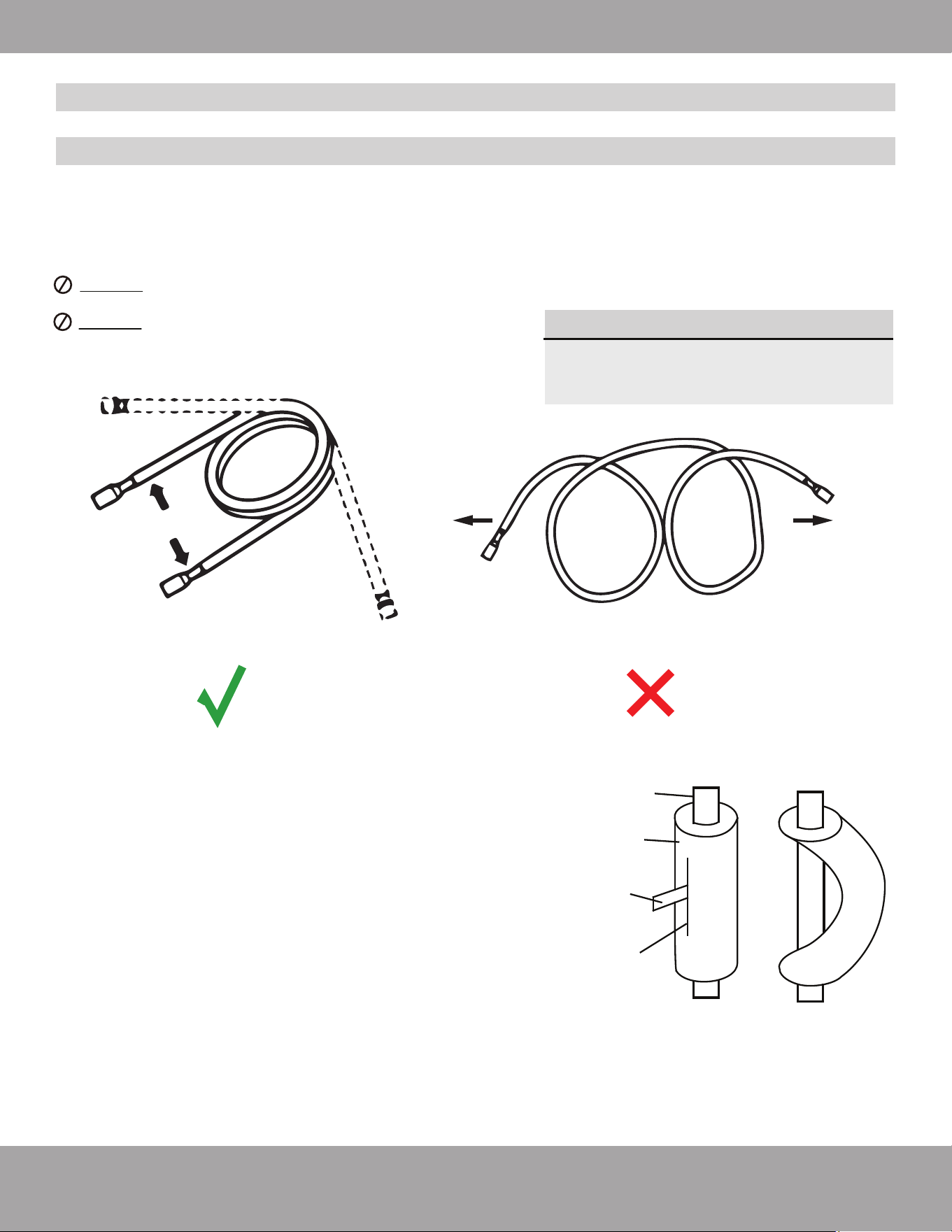
Please read and follow the instruc�ons and diagram below
*
:
1.
Take out matching male connectors M1 and M2.
2.
Remove protec�ve cap with the copper gasket at each stop valve on the DC INVERTER
and ensure the threads are clean and complete.
3.
Tighten the M1 connector to the cutoff valve *1 with a �ghtening force of 37 �/lb (50 Nm).
Tighten the M2 connector to the cutoff valve *2 with a �ghtening force of 52 �/lb (70.5 Nm).
4.
Repeat step 3 for AIR HANDLER at the other end of the LINE SET.
5.
Unroll and route the LINE SET between the AIR HANDLER and the DC INVERTER. Bend the
line set by hand to route the line set to suit your applica�on. Use care when bending the line
set. Please refer to Fig. 2.15 on Pg. 19 for more detailed instruc�ons on how to properly
and safely bend refrigerant piping, as well as the correct bend radius.
6.
Remove the protec�ve caps of the valves at both ends of the LINE SET. Verify that all
threads are clean and complete.
7.
Tighten the LINE SET F1 valve to the M1 Connector (a�ached in step 3) with a force
of 33 �/lb (45 Nm). Tighten the LINE SET F2 valve to the M2 Connector (a�ached in step 3)
with a �ghtening force of 48 �/lb (65 Nm).
8. Repeat this process for the AIR HANDLER at the other end of the LINE SET.
Connec�ons must be made exactly as specified to avoid system leaks and /or damage
9.
At the OUTDOOR UNIT remove the protec�ve cap at the cutoff valve switch and open the
cutoff valve with a hex wrench to release refrigerant into the system. If there is any fizz,
grease or other leakage, then close the valve immediately and check that steps 3 and 7
were done properly. Otherwise, using a sponge or spray bo�le, apply a soapy water solu�on
to the connec�on points to check for micro leaks. If any bubbles form it indicates there is a
leak. If this does occur, close the valve immediately and check that steps 3 and 7 were done
properly and re-�ghten the valves and line set if necessary.
10. A�er the correct connec�on, re-�ghten the
cutoff
valve’s protec�on cap and cover the
M1, M2 and F1, F2 connec�ons with the gray insula�ng sleeve to help prevent
condensa�on.
NOTE ON WRENCHES
The wrench sizes needed for tightening the
No-Vac
®
Quick Connect
®
Line Set are listed
below. However, based on the availability of the
wrench sizes needed, it is recommended to use
two large crescent (adjustable-type) wrenches.
Using one to hold the valve while using the
other wrench to tighten the line set connector.
IMPORTANT
The stop/cutoff valves on the unit must
be opened AFTER connecting the lines
and BEFORE turning on the unit.
Otherwise, operation can cause leakage
and/or damage to the unit.
Piping Size
(Stamped on piping)
Allen/Hex Wrench Sizes Needed
To Open Stop/Cutoff Valves
Wrench Size Required
Standard Metric
Allen Wrench Size
1”3/8”
3/8”
25 mm
1-3/8”3/4”
3/4”
35 mm
5 mm
8 mm
Piping/Valve Size
(Stamped on piping)
Or 2x large crescent (adjustable-type)
wrenches
*Pat. https://mrcool.com/mrcool-patents/
ⱡFailure to follow the instrucons provided could result in severe harm to you, this product, or other property.
The manufacturer, distributor, and seller are not responsible for any harm resulng from the failure to follow
instrucons and the failure to follow these instrucons will void any and all warranes express or implied.
Page 25
mrcool.com
Unit Installation
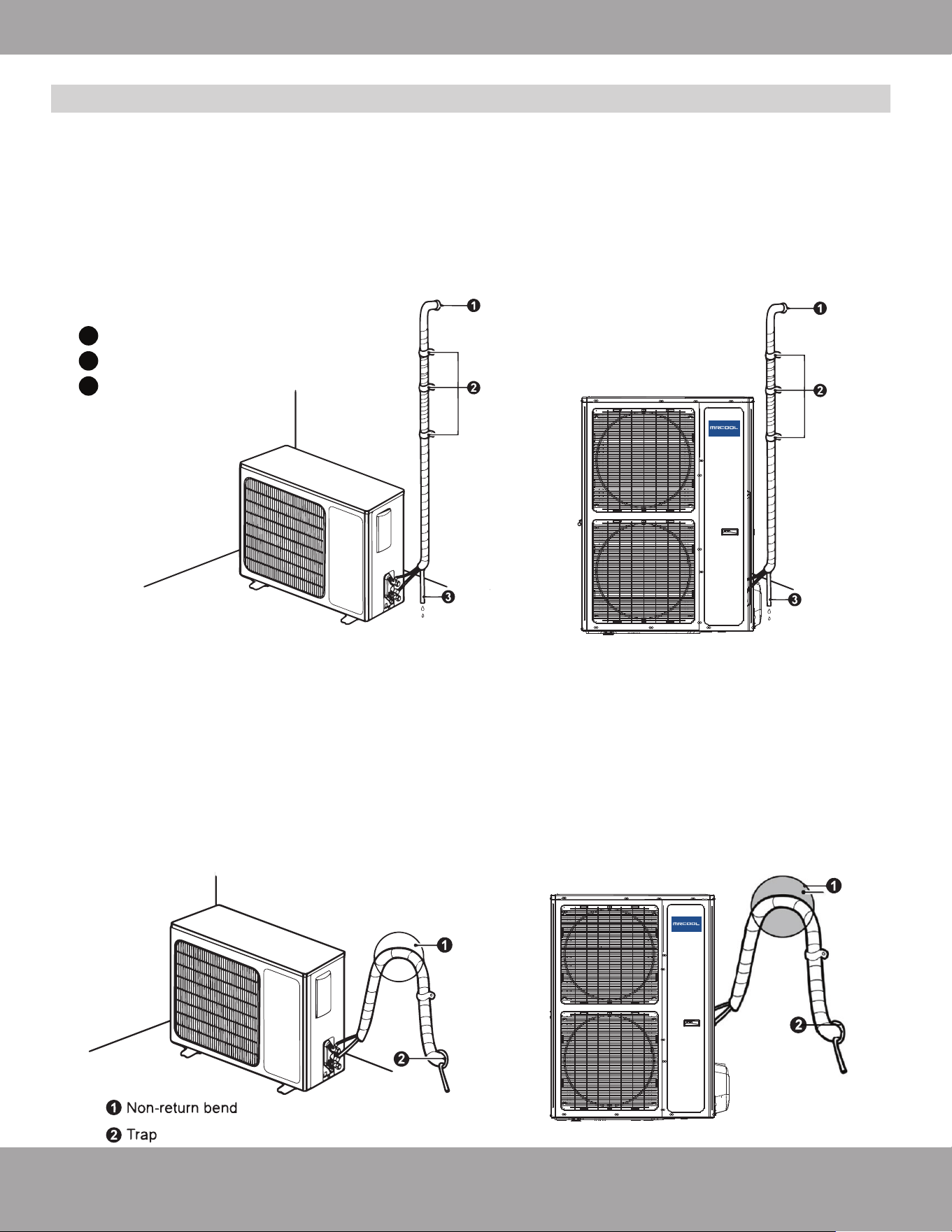
If the outdoor unit is located on a level lower than the indoor unit, arrange the condensate drain
according to Fig. 2.21.
1.
Drain hose should be placed on the ground and its end should not be immersed into water.
2.
The entire line set, including drain pipe should be wound with insulating tape. Wrap the insulating tape
from bottom to top, as this will ensure rain/moisture does not seep into the tape overlaps.
3.
The entire line set, including drain pipe should be supported and fixed onto the wall with saddles.
Installation of Drain Pipe
Fig. 2.21
1
2
3
Sealed
Saddle
Drain Pipe
®
MDUC018024036
MDUC018048060
Fig. 2.22
®
MDUC018024036
MDUC018048060
If the outdoor unit is located on a level higher than the indoor unit, arrange the condensate drain
according Fig. 2.22.
1.
Drain hose should be placed on the ground utilizing a trap.
2.
The entire line set, including drain pipe should be wrapped with insulating tape to avoid water returning
to the interior. Wrap the insulating tape from bottom to top, as this will ensure rain/moisture does not
seep into the tape overlaps.
3.
The entire line set, including drain pipe should be supported and fixed onto the wall with saddles.
mrcool.com
Page 26
Unit Installation
Condenser Field Conversion
Fig. 2.23
Location of
Dip Switch on
Condenser
Main Board
DEFAULT 3 TON
2 TON SETTING
Fig. 2.23
Fig. 2.24
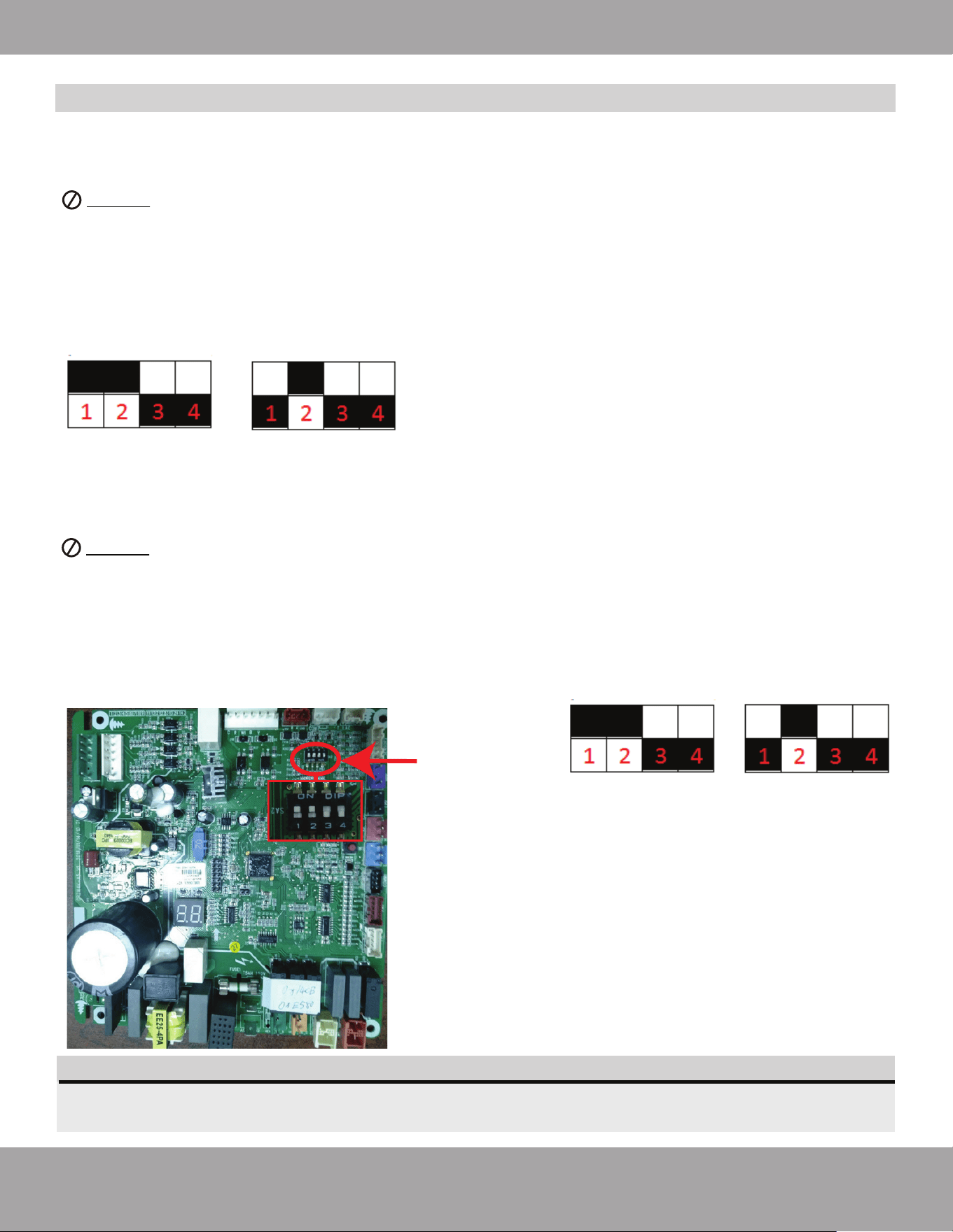
Follow these instructions during unit installation in order to enable a Universal
®
Series 3-ton condenser and
air handler split system to operate at 2-ton capacity.
DO NOT attempt this conversion while the unit is powered on.
1. Locate the capacity dip switch on the condenser main board. The capacity dip switch is circled in the
photo below.
2. The default position of the capacity dip switch is 1 & 2 ‘Up’ and 3 & 4 ‘Down’. Up being a switch pushed
toward the letters (ON DIP). Down being a switch pushed toward the numbers (1 2 3 4).
3. The default position of the capacity dip switch is 36K.
4. To activate the 24K capacity, flip capacity dip switch 1 from the Up position to the Down position.
Converting Unit From 3-Ton to 2-Ton
NOTE
Refer to the Universal Air Handler Installation Manual for Dip Switch Instructions and settings to
convert the Universal Air Handler from 3-ton to 2-ton, or 5-ton to 4-ton.
Converting Unit From 5-Ton to 4-Ton
Follow these instructions during unit installation in order to enable a Universal
®
Series 5-ton condenser and
air handler split system to operate at 4-ton capacity.
DO NOT attempt this conversion while the unit is powered on.
1. Locate the capacity dip switch on the condenser main board. The capacity dip switch is circled in the
photo below.
2. The default position of the capacity dip switch is 1 & 2 ‘Up’ and 3 & 4 ‘Down’. Up being a switch pushed
toward the letters (ON DIP). Down being a switch pushed toward the numbers (1 2 3 4).
3. The default position of the capacity dip switch is 60K.
4. To activate the 48K capacity, flip capacity dip switch 1 from the Up position to the Down position.
Fig. 2.25
DEFAULT 5 TON
4 TON SETTING
Fig. 2.26
Page 27
mrcool.com
Unit Installation
WARNING Before performing electrical work, read the following regulations
1. Electrical installation must be conducted only by professionals in compliance with local laws,
regulations and this installation manual.
2. Never artificially extend the length of the power cord.
3. The electric circuit must be equipped with a circuit breaker and air switch. Both must have
sufficient capacity.
4. Unit operating power must be within the nominal range stated in the instruction manual. Use a
specialized power circuit for the air conditioner. DO NOT draw power from another power circuit.
5. The air conditioner circuit should be at least 5 ft (1.5 m) away from any flammable surface.
6. The external power cord and the thermostat wire must be effectively fixed.
7. The external power cord and the thermostat wire must NOT directly contact any hot objects. For
example: they must not come into contact with chimney pipes, warm gas pipes, or other
heat-producing objects.
8. The external power cord and the thermostat wire must NOT be squeezed. Never pull, stretch or
bend the wires.
9. The external power cord and the thermostat wire must NOT collide with any metal beam or edge
on the ceiling, or touch any metal burrs or sharp metal edges.
10. Connect wires correspondingly by referring to the circuit diagram labeled on the unit or electric
box. Ensure screws are tightened securely. Slipped screws must be replaced by specialized
flat-head screws.
11. The wire gauge of the power cord should be sufficiently large. A damaged power cord or other
wires must be replaced by specialized wires. Wiring work must be done according to national
wiring rules and regulations.
12. Wiring terminals should be connected firmly to the terminal board.
***Disclaimer: Wiring must meet code specs according to the capacity/tonnage of the unit.***
Electrical Connection
Electrical Regulations
Page 28
mrcool.com
Unit Installation
Outdoor Unit Model Power Supply
Max. Overcurrent
Protection
208/230V
1Ph - 60Hz
35 amps
35 amps
MDUCO18024036
Min. Circuit
Ampacity
MDUCO18048060
45 amps
45 amps
Fuse Capacity
(A)
24 amps
35 amps
Electrical Connection
Electrical Parameters
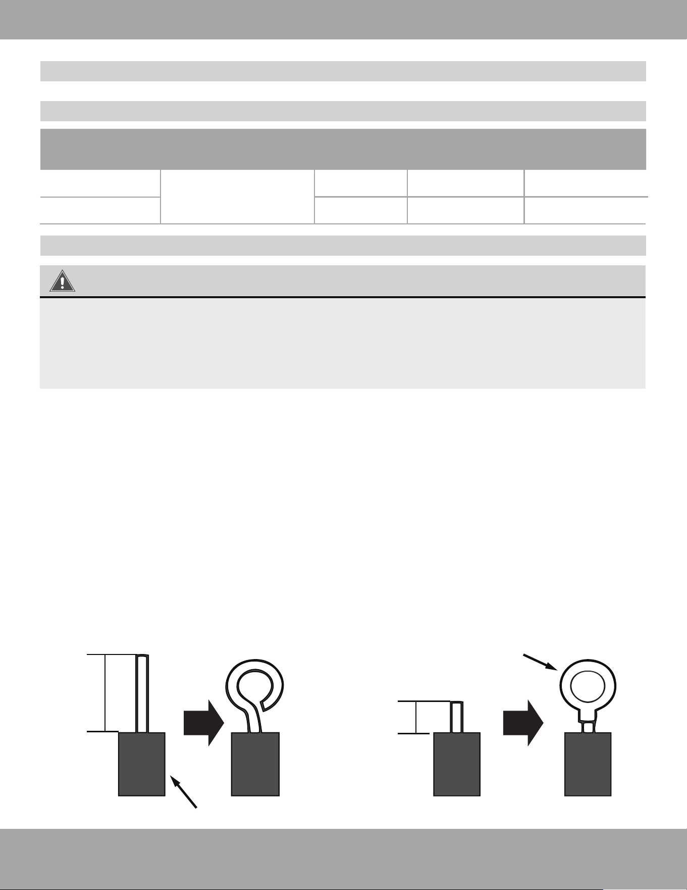
Connecting the Power Cord & Thermostat Wire
For solid wires (Refer to Fig. 2.27 A):
1. Use wire cutters to cut off the wire end and then peel away about 1 in (25 mm) of the insulation layer.
2. Use a screwdriver to unscrew the terminal screw on the terminal board.
3. Use nippers to bend the solid wire into a ring that fits the terminal screw.
4. Form a proper ring and then put it on the terminal board. Use a screwdriver to tighten up the
terminal screw
For braided wires (Refer to Fig. 2.27 B & Fig. 2.28):
1. Use wire cutters to cut off the wire end and then peel away about 3/8 in (10 mm) of the insulation layer.
2. Use a screwdriver to unscrew the terminal screw on the terminal board.
3. Use a round terminal fastener or clamp to fix the round terminal firmly on the peeled wire end.
4. Locate the round terminal conduit. Use a screwdriver to replace it and tighten up the terminal screw
(as shown in Fig. 2.28).
A. Solid Wire
Insulation Layer
1 in (25 mm)
B. Braided Wire
Solderless
Terminal
3/8 in (10 mm)
Fig. 2.27 B
Fig. 2.27 A
WARNING
1. Before work begins, please check to ensure the unit is powered OFF.
2. Improper wire connection may cause electrical components to burn.
3. Connect the wires firmly to the wiring box. Incomplete installation could create a fire hazard.
4. Ground wire must be securely connected.
Page 29
mrcool.com
Unit Installation
Electrical Connection
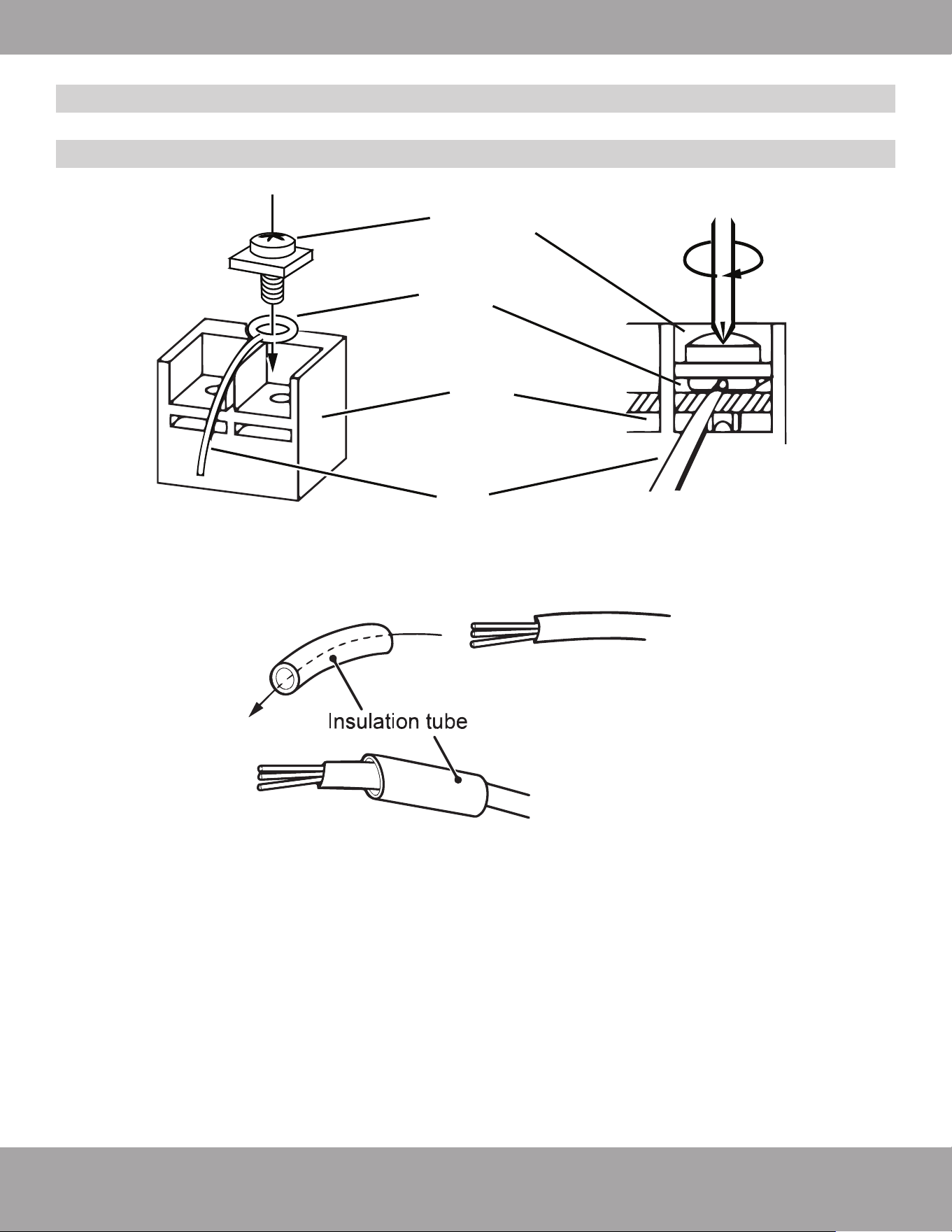
Connecting the Power Cord & Thermostat Wire
Screw with
special washer
Round
Terminal
Wire
Terminal
Board
For all terminal wiring (Refer to Fig. 2.29):
5. Lead the thermostat wire and power cord through the insulation tube (as shown in Fig. 2.29).
Fig. 2.29
Fig. 2.28
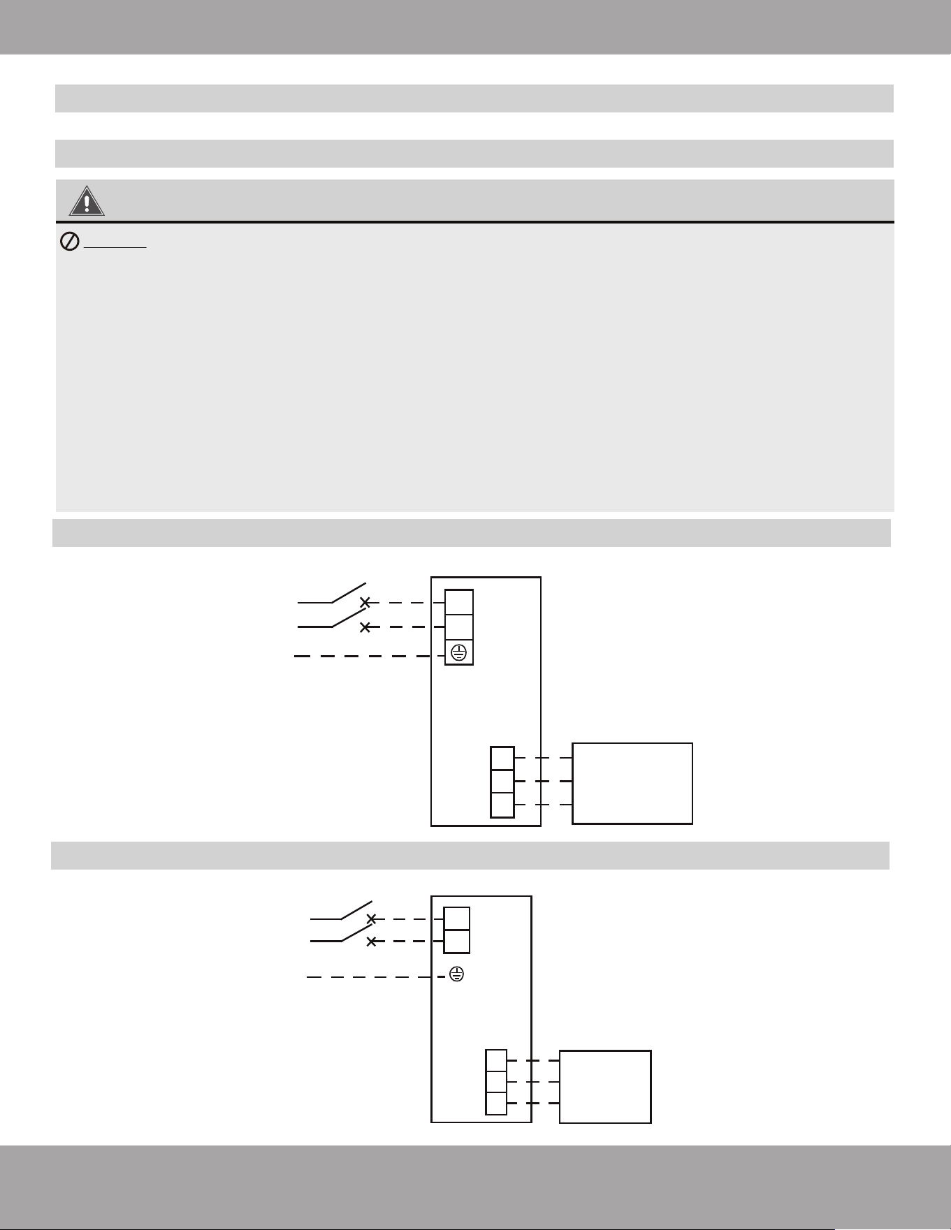
POWER
Breaker
208-230V L1
1PH L2
60Hz
G
L1
L2
Outdoor
Unit
Y
R
C
Electrical wiring of Single-phase unit: MDUCO18048060
Fig. 2.30-B
Thermostat
Page 30
mrcool.com
Unit Installation
WARNING
DO NOT bundle up the temperature thermostat wires and power wires, or lay them side by
side, otherwise errors will occur.
1. High and low voltage wires should be led through different rubber rings of the electric box cover.
2. High and low voltage wires should be secured separately.
3. Use screws to tighten the power cord and thermostat wire of the units on the terminal board. An
improper connection could create a fire hazard.
4. If the power cord and thermostat wires are not correctly connected, the air conditioner may suffer
damage.
5. Ground the units through connecting the ground wire and ensure it is secure.
6. The units should comply with applicable local and national rules and regulations on power
consumption.
7. When connecting the power cord, make sure the phase sequence of the power supply matches with
the corresponding terminals, otherwise the compressor will get reversed and operate abnormally.
POWER
Breaker
208-230V L1
1PH L2
60Hz G
L1
L2
Outdoor
Unit
R
C
Thermostat
Y
Electrical wiring of Single-phase unit: MDUCO18024036
Electrical Connection
Connecting the Power Cord & Thermostat Wire
Fig. 2.30-A
Page 31
mrcool.com
Unit Installation
Electrical Connection
Connecting the Power Cord & Thermostat Wire
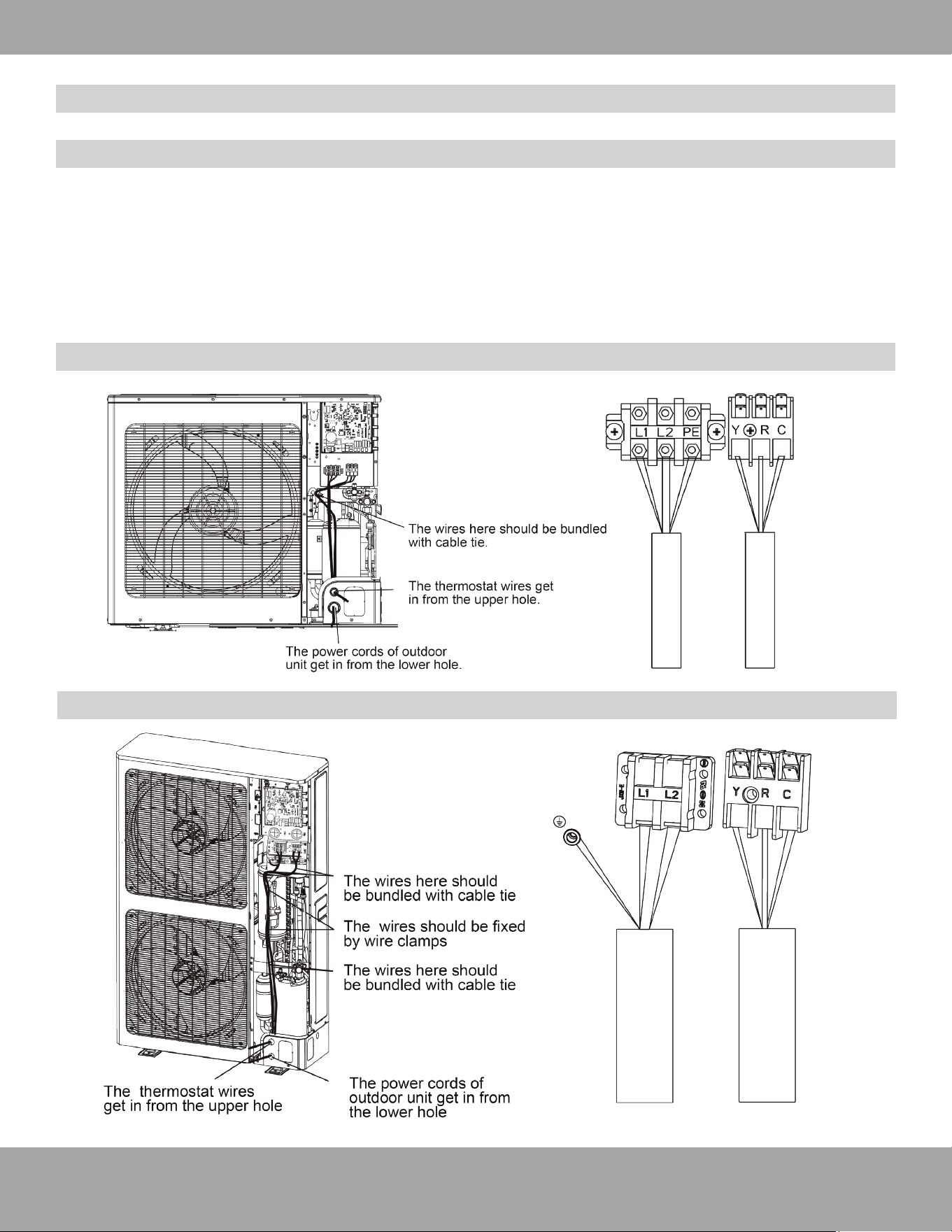
Electrical wiring of Single-phase unit: MDUCO18024036
1. Remove the big handle/front panel of the outdoor unit and insert one end of the thermostat wire and the
power cord to the terminal board.
2. The power cord should be secured along with the front side plate and fixed to the hook with a wire clamp
so as to avoid contacting the pipeline. The temperature thermostat wire should also be laid along with
the front side plate but away from the power cord.
Electrical wiring of Single-phase unit: MDUCO18048060
Page 32
mrcool.com
Refrigerant Piping Connection
Before Test Run
Only perform test run after you have completed the following steps:
• Electrical Safety Checks – Confirm that the electrical system is safe and operating properly.
• Gas Leak Checks – Check refrigerant piping connections/valves and confirm the system is not leaking.
• Confirm that gas and liquid (high and low pressure) valves are fully opened.
3
Post Installation Checks
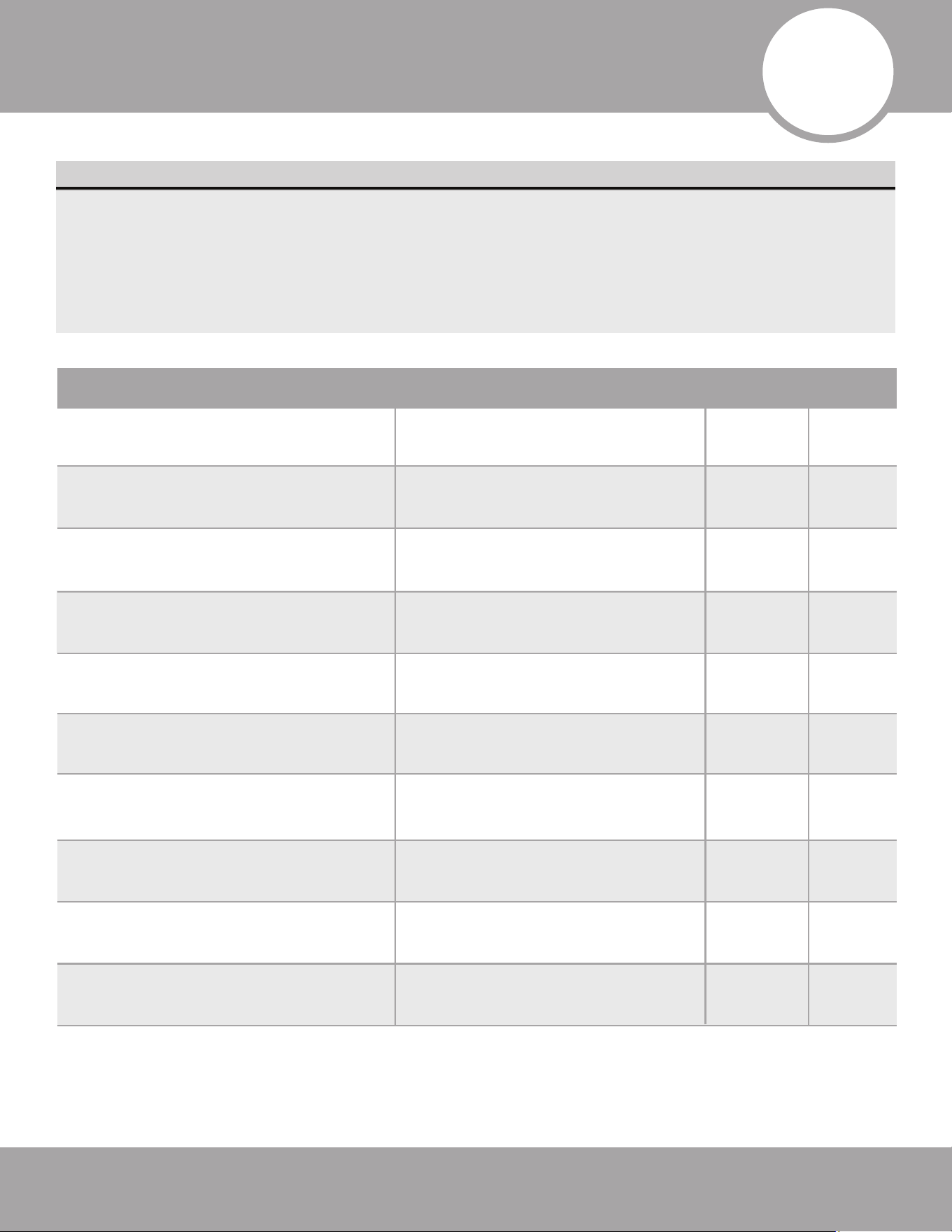
List of Checks to Perform Possible Malfunctions PASS/FAIL
Is the main body installed securely?
The unit may fall down, vibrate or
produce noise.
Did you conduct a water leakage test? Cooling capacity may become
inadequate.
Is the unit well insulated from heat?
Condensate/water droplets may
occur.
Does water drain properly from drain
hose?
Condensate/water droplets may
occur.
Is the voltage consistent with the
specifications stated on the nameplate?
The unit may fail or its components
may get burned.
Are the wires, piping, and valves
installed correctly?
The unit may fail or its components
may ignite.
Has the unit been safely grounded?
Could create a risk of electrical
leakage.
Do the wire specifications comply with
the requirements?
The unit may fail or its components
may ignite.
Are there any obstacles blocking the air
inlet or outlets of the units?
Cooling capacity may become
unsatisfactory.
Have you recorded the length of
refrigerant pipe and the refrigerant
charge amount?
The refrigerant charging amount
cannot be controlled.
Outdoor (2): Indoor (2):
Outdoor (2): Indoor (2):
Page 33
mrcool.com
Post Installation Checks
Test Run Instructions
Preparation before connecting the power:
DO NOT connect power unless installation has been fully completed.
1. Control circuit is correct and all the wires are firmly and securely connected.
2. Stop/Cut-off valves of the gas pipe and liquid pipe are fully opened.
3. The inside of the unit should be clean. Remove irrelevant objects and debris if there are any.
4. After checking, re-install the front side plate.
Operation after connecting the power:
1. If all the steps above have been completed, power on the unit.
2. Make sure the units run normally.
3. If there are any loud and/or abnormal sounds contact MRCOOL
®
Tech Support immediately,
at (270) 366-0457.
NOTICE:
1. If you use the thermostat to turn off the unit and then immediately turn the unit on again, the compressor
will need 3 minutes to restart. Even if you press “ON/OFF” button on the thermostat, it will not start up
right away. This is to protect the compressor.
2. If there is no display on the temperature thermostat, it is probably because the connection wires between
the unit and the temperature thermostat are not connected. Connect them if necessary and recheck
the display.
DOUBLE-CHECK PIPE CONNECTIONS
During operation, the pressure of the refrigerant circuit will increase. This may reveal leaks that were
not present during your initial leak check. Take time during the Test Run to double-check that all
refrigerant pipe connection points do not have leaks.
Test Run

Page 34
mrcool.com
Outdoor Unit Installation
Maintenance
4
4
Maintenance
Troubleshooting
(1) If your air conditioner fails to function normally, check the following items before conducting maintenance:
Problem Cause Corrective Measure
The air conditioner
will not activate.
Inadequate cooling
If you turn off the unit and then
immediately turn it on, in order to
protect the compressor and avoid
system overload, compressor will
delay running for 3 minutes.
Wire connections are incorrect.
Fuse or circuit breaker is broken.
Power failure.
Please wait for approx. 3 minutes.
Connect wires according to the
wiring diagram.
Replace the fuse or switch on the
circuit breaker.
Restart once power is restored.
Wired connection or power plug is
loose.
Re-insert or adjust wires for proper
connections to designated terminals.
Air inlet and outlet of the units are
blocked.
Clear the obstacles and keep the
area well ventilated.
Improper temperature setting. Reset to a proper temperature.
Fan speed is too low. Reset to a proper fan speed.
Airflow direction is incorrect. Change the direction of air louvers.
Doors and/or windows are open. Close them.
Air inlet and outlet of the units are
blocked.
Clear the obstacles and keep the
area well ventilated.
Exposed to direct sunlight.
Close curtains or louvers in front of
the windows.
Too many heat sources in the room. Remove unnecessary heat sources.
Filter is blocked or dirty. Replace with a new return filter.

Page 35
mrcool.com
Maintenance
Problem Time of Occurrence Cause
Mist comes from
the conditioner.
The air conditioner
generates noise.
The air conditioner
generates smells.
Dust comes from
the air conditioner.
During operation.
The air conditioner is buzzing when
operation begins.
When the unit is turned on, it purrs.
If the unit is running under high
humidity, the wet air in the room will
be quickly cooled down.
Thermostat will be buzzing
when it starts working. The noise will
become weak 1 minute later.
When the system has just started,
the refrigerant is not stable. About 30
seconds later, the purr of the unit
becomes low.
The unit starts operation after being
unused for a long time.
Dust from inside the units is
dispersed with the supply airflow.
During operation.
Smells from the operating
environment may be pulled through
the air handler and dispersed
throughout the rooms.
It is the sound of gaseous refrigerant
that has stopped flowing or changed
direction, and the sound of the
drainage system.
There is a hissing sound when the
unit has been turned on, or stopped
suddenly during operation, or after
defrosting.
Because of temperature change, the
front panel and other components
may swell and cause an abrasive
sound.
There is a crunching sound during
and after operation.
(2) The following situations are not operation failures.
NOTICE
Check the above items and take appropriate corrective measures. If the air conditioner continues to
improperly function, please turn off the air conditioner immediately and contact MRCOOL
®
Tech Support,
at (270) 366-0457, or your installing dealer.
Page 36
mrcool.com
Maintenance
Error Code
WARNING
• When abnormalities occur, stop the unit immediately and disconnect power. Contact MRCOOL
®
Tech Support, at (270) 366-0457. If the unit continues to run abnormally, it may damage the unit
and cause an electric shock and/or a fire hazard.
DO NOT attempt repairs to the appliance yourself. Improper repair and maintenance can
create electric shock and/or fire hazards. Please contact MRCOOL Tech Support, at the phone
number above, for further guidance or a qualified professional for repairs.
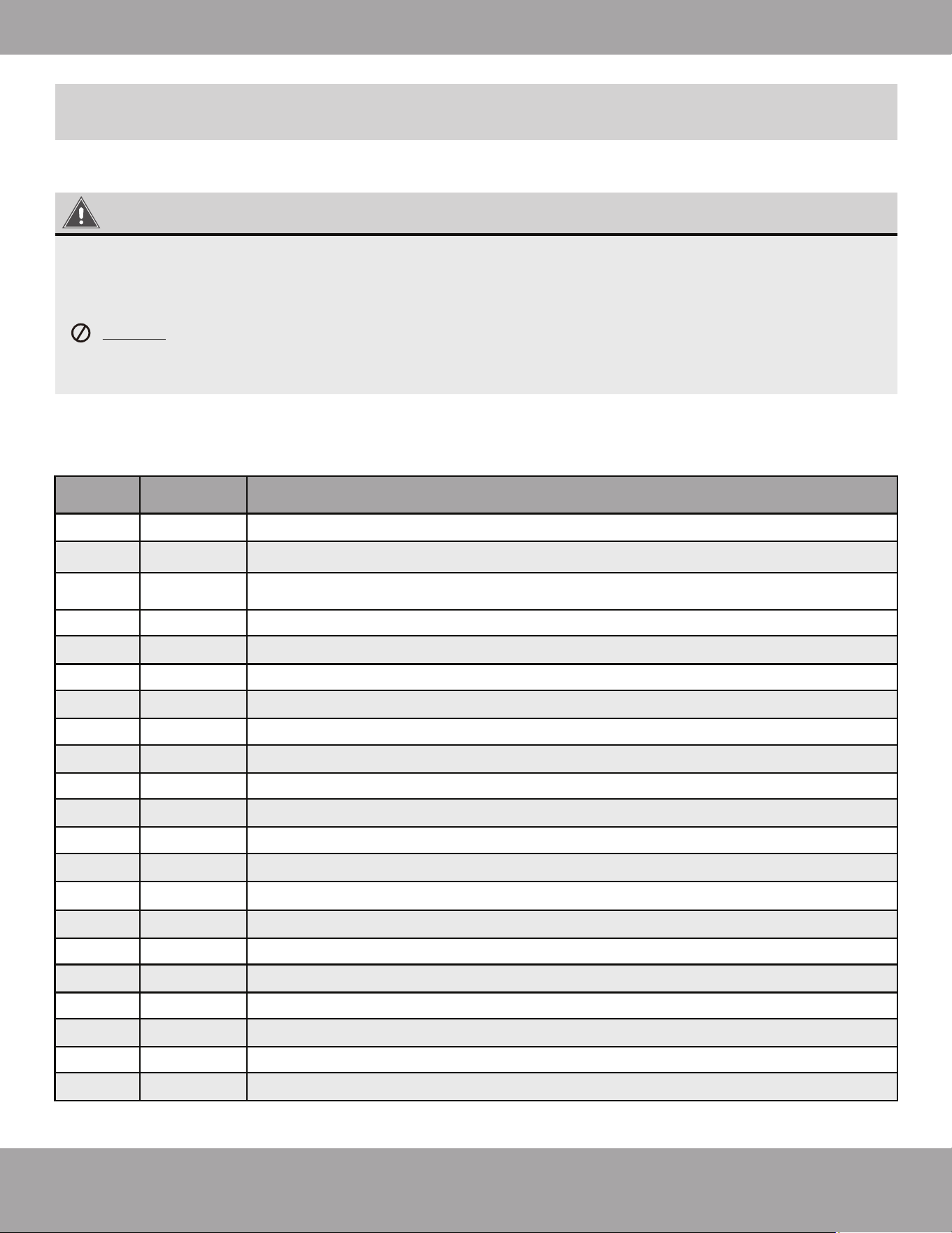
Number Error Code Error
1 E1 Compressor high pressure protection
2
E4 Compressor air discharge high-temperature protection
4 F2 Condenser temperature sensor error
5 F3 Outdoor ambient temperature sensor error
6 F4 Discharge temperature sensor error
7 F6 Outdoor unit tube temperature sensor error
8
9
EE Outdoor unit memory chip error
10
11
12
H4 Overload
13
H5 IPM protection
14
H6 DC fan error
15
H7 Driver out-of-step protection
16
HC Pfc protection
17
Lc Startup failure
18
19
20
21
P0 Drive reset protection
3
E3
Compressor low pressure protection
If the LED display panel on the main board of the outdoor unit displays an error code, please refer
to the following table:
P6
Master control and driver communication error
Driver module sensor error
P8 Driver module high temperature protection
P7
P5 Over-current protection
PA AC current protection
Pc Driver current error
Page 37
mrcool.com
Maintenance
Unit Maintenance
Number Error Code Error
22
23
25
26
27
PL Bus low-voltage protection
PH
Bus high-voltage protection
PU
Charge loop error
ee
Driver memory chip error
e3 Low pressure sensor error
C4 ODU jumper cap error
24
Warning
1) Only professionals may carry out annual maintenance.
2) Before contacting any wire, make sure power is turned off.
4) Do not use organic solvent to clean the air conditioner.
5) If you need to replace a component, contact a professional to repair the unit with a
component supplied by MRCOOL® to ensure the quality.
6) Improper operation may damage the unit, causing electric shock or fire.
7) Do not immerse the air conditioner in water or electric shock could occur. Also, do not use
water to rinse the unit during cleaning.
3) Do not allow flammable objects near the unit.
Warning
1) Before cleaning, ensure the power is off. Turn off at circuit breaker and remove the
disconnect, to avoid electric shock.
3)
4)
Use care when cleaning the filter.
If you need to work from an elevated position (such as on a ladder), please exercise caution.
2) Do not wash the air conditioner with water, otherwise fire and/or electric shock may occur.
Page 38
mrcool.com
Maintenance
Outdoor Heat Exchanger
Condensate Drain
Periodically check if the condensate drain is blocked to avoid condensate backing up into the system, as
this could cause property damage and/or the unit to fail.
Clean the heat exchanger on the outdoor unit, at least once every two months. Remove the dust and debris
on the surface of the heat exchanger with a dust collector and nylon brush. If there is a compressed air
source; use the compressed air to gently blow the dust off the surface of the heat exchanger.
DO NOT use tap water for cleaning.
Pre-Season Inspection Check List
1. Check for blockages in the air inlet/outlet.
2. Check the ground connection and make sure it is still securely connected.
3. Check that the air filter screen is properly installed and clean.
4. If starting up the unit after a long period of inactivity, flip the power switch of the air conditioner to “ON”
status at least 8 hours prior to operation. This is to preheat the crankcase on the compressor.
5. Check that the outdoor unit is firmly secured.
6. If problems are detected, contact your local service professional or MRCOOL
®
Tech Support,
at (270) 366-0457.
Post-Season Maintenance Check List
1. Deactivate the main power to the air conditioner;
2. Remove dust and debris from the outdoor unit;
3. If the outdoor unit is rusty, paint the location with anti-rust paint to prevent it from continuing to spread.
Components are available from MRCOOL
®
and associated dealers.
Component Replacement
Unit Maintenance
Page 39
mrcool.com
Maintenance
Notice on Maintenance
Service Information
General Work Area
Inform others working in the immediate vicinity about the nature of work being performed. Avoid working in
confined spaces. Section off the area around the workspace. Ensure conditions within the area are safe by
removing potentially flammable material.
The manual contains specific information for service personnel who will perform maintenance on the product.
Ventilated Area
Ensure the area is adequately ventilated before opening the system or conducting any refrigerant work. Maintain
adequate ventilation while working. Effective ventilation will safely disperse any released refrigerant into the
atmosphere.
Refrigeration Equipment Checks
Ensure all electrical components are compatible with the product and built to the correct specifications. Follow
manufacturer maintenance and service guidelines at all times. When in doubt, consult the MRCOOL
®
Technical
Department, at (270) 366-0457, for further assistance.
If using flammable refrigerants, conduct the following checks:
1. Ensure ventilation machinery and outlets are operating adequately and are not obstructed.
2. If an indirect refrigerating circuit is being used, check the secondary circuit for the presence of refrigerant.
3. Check that equipment markings are visible and legible. Replace markings that are illegible.
4. Ensure refrigeration piping or components are installed in a position where they are unlikely to be exposed
to any substance which could corrode refrigerant containing components, unless the components are
constructed of materials which are inherently resistant to being corroded, or are suitably protected
against corrosion.
Electrical component repair and maintenance should include initial safety checks and component inspection
procedures.
DO NOT connect the circuit to an electrical supply If a fault exists that could compromise safety.
The fault must be corrected.
Electrical Device Checks

Page 40
mrcool.com
Maintenance
Initial safety checks should include:
1. Safe discharge of capacitors to avoid the possibility of sparking.
2. No live electrical components and wiring should be exposed while charging, recovering, or purging
the system.
3. The system is safely grounded.
Electrical Device Checks (cont.)
DO NOT apply any permanent inductive or capacitance loads to the circuit without first ensuring
that this will not exceed the permissible voltage and current permitted for the equipment in use.
1. Intrinsically safe components are the only types that can be worked on while live in the presence of a
flammable atmosphere. The test apparatus must be at the correct rating.
2. Replace components only with parts specified by the manufacturer. Other parts may result in the ignition of
refrigerant in the atmosphere from a leak.
Intrinsically Safe Component Repair
Sealed Component Repairs
ELECTRICAL SAFETY
Ensure that this system is installed using a disconnect box that meets national, state, and local electrical
and HVAC code requirements. The location of the disconnect box(es), number of disconnect boxes
needed, and distance from the unit(s) to the disconnect box(es) should be handled in accordance with
national, state, and local electrical and HVAC code. Also ensure that there is a permanent form of leak
detection, at the most critical point to warn of a potentially hazardous situation.
ATTENTION
• Electrical component casings should not be altered in such a way that the level of protection is
affected. This includes damage to cables, excessive number of connections, terminals not made to
original specification, damage to seals, incorrect fitting of glands, etc.
• Ensure the apparatus is securely mounted.
• Ensure the seals or sealing materials have not degraded in such a way that they no longer serve the
purpose of preventing the ingress of flammable atmospheres.
• Replacement parts should be in accordance with manufacturer specifications.
NOTICE
• The use of silicon sealant may inhibit the effectiveness of some types of leak detection equipment.
• Intrinsically safe components do not have to be isolated prior to working on them.
Notice on Maintenance
Page 41
mrcool.com
Maintenance
Notice on Maintenance
Cabling
Charging Procedures
Decommissioning
Before decommissioning, it is essential that the technician become completely familiar with all of the
equipment in detail. It is recommended, and good practice, that all refrigerants be recovered safely. Before
decommissioning, an oil and refrigerant sample should be taken. This is in case an analysis is required prior to
the re-use of the reclaimed refrigerant. It is essential that electrical power is available before the task is
commenced.
Before decommissioning procedure, ensure the following:
1. You are familiar with the equipment and its operation.
2. The system has been isolated electrically.
3. Mechanical handling equipment is available, if required, for handling refrigerant cylinders.
4. All personal protective equipment is available and being used correctly.
5. The recovery process is supervised at all times by a competent person.
6. Recovery equipment and cylinders conform to the appropriate standards.
Decommissioning procedure:
1. Pump down refrigerant system, if possible.
2. If a vacuum is not possible, make a manifold so that refrigerant can be removed from various parts of
the system.
3. Make sure that cylinder is situated on the scales before recovery takes place.
4. Start the recovery machine and operate in accordance with manufacturer's instructions.
DO NOT overfill cylinders. Cylinders should have no more than an 80% volume of liquid charge.
Check that cabling will not be subject to wear, corrosion, excessive pressure, vibration, sharp edges, or any
other adverse environmental effects. The check should also take into account the effects of aging or continual
vibration from sources such as compressors or fans.
In addition to conventional charging procedures, the following parameters must be followed:
1. Ensure refrigerant contamination does not occur when charging equipment.
2. Hoses or lines should be as short as possible to minimize the refrigerant contained in them.
3. Cylinders must be kept upright.
4. Ensure that the system is securely and properly grounded prior to charging the system with refrigerant.
5. Take extreme care to avoid refrigerant overfill.
6. Label the system when charging is complete (if not already).
7. Extreme care shall be taken not to overfill the refrigeration system.
8. Prior to recharging the system pressure test with OFN. The system must be leak tested when charging is
complete and prior to commissioning. A follow up leak test must be carried out before leaving the site.

Page 42
mrcool.com
Maintenance
DO NOT exceed the maximum working pressure of the cylinder, even temporarily.
6. When the cylinders have been filled correctly and the process completed, ensure the cylinders and the
equipment are removed from site promptly and all isolation valves on the equipment are closed.
7. Recovered refrigerant must not be charged into another refrigeration system until it has been cleaned
and checked.
When removing refrigerant from a system, either for servicing or decommissioning, it is a recommended, and
always a good practice, that all refrigerants are removed safely.
When transferring refrigerant into cylinders, ensure that only appropriate refrigerant recovery cylinders are
employed. Ensure that the correct number of cylinders for holding the total system charge are available.
Ensure that all cylinders to be used are designated for the recovered refrigerant and labeled for that
refrigerant. Cylinders should be complete with pressure relief valve and associated shut-off valves in good
working order.
In addition, a set of calibrated weighing scales should be available and in good working order. Hoses shall be
complete with leak-free disconnect couplings and in good condition. Before using the recovery machine, check
that it is in satisfactory working order and has been properly maintained. Consult the manufacturer if in doubt.
The recovered refrigerant should be returned to the refrigerant supplier in the correct recovery cylinder, and
the relevant Waste Transfer Notice arranged.
DO NOT mix refrigerants in recovery units and especially not in cylinders.
If compressors or compressor oils are to be removed, ensure that they have been evacuated to an acceptable
level to make certain that flammable refrigerant does not remain within the lubricant. The evacuation process
shall be carried out prior to returning the compressor to the suppliers. Only electric heating to the compressor
body should be employed to accelerate this process. When oil is drained from a system, it should be carried
out safely.
Notice on Maintenance
Decommissioning (cont.)
Labeling
Recovery
After-Sales Services
Equipment should be labeled to state that it has been decommissioned and emptied of refrigerant. The label
must be dated and signed.
Any quality or other issues encountered in the purchased air conditioner, please contact the local MRCOOL
®
after-sales service department.
Page 43
mrcool.com
Refrigerant Piping Connection
Special notice
This appliance contains refrigerant and other potentially hazardous materials. When disposing of this
appliance, the law requires special collection and treatment.
DO NOT dispose of this product as household waste or unsorted municipal waste.
When disposing of this appliance, you have the following options:
• Dispose of the appliance at a designated municipal electronic waste collection facility.
• When buying a new appliance, the retailer will receive the old appliance free of charge.
• The manufacturer will receive the old appliance free of charge.
• Sell the appliance to certified scrap metal dealers.
Disposing of this appliance in the forest or other natural surroundings endangers your health and is bad
for the environment. Hazardous substances may leak into the ground water and enter the food chain.
6
EU Disposal Guidelines
Universal
®
Series
The design and specifications of this product and/or manual are subject to change without prior notice.
Consult with the sales agency or manufacturer for details.
Copyright © 2021 MRCOOL, LLC.
ELECTRICIAN and/or HVAC TECHNICIAN:
LICENSE #:
INSTALLATION DATE:
INSTALLATION LOCATION:
SERIAL NUMBER: