© 2024 TP-Link 7106511761 REV1.0.0
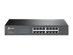
Front Panel
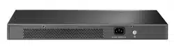
Rear Panel
Appearance
LEDs
On: The switch is powered on.
O: The switch is powered o or power supply is abnormal.
Flashing: Power supply is abnormal/Loop Prevention function is enabled.
For simplicity, we will take LS1024G for example.
Power
On: A device is linked to the corresponding port and running properly.
O: No device is linked to the corresponding port.
Flashing: Transmitting or receiving data.
Link/Act
The switch already comes with lightning protection mechanism. You can also
ground the switch through the PE (Protecting Earth) cable of AC cord or with
Ground Cable.
Grounding Terminal
Others
Plug the female connector of the power cord directly into the power socket and
plug the male connector into an AC outlet. Make sure that the voltage of the power
supply meets the requirement of the input voltage (100–240 V ~ 50/60 Hz).
Power Socket
The images are for demonstration only and may dier from your actual product.
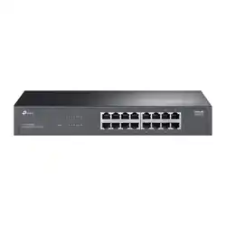
Feet
Bottom of the Device
Notch
Rack-mounting Bracket
Screw
Rack
Method 1: Desktop Installation Method 2: Rack Installation
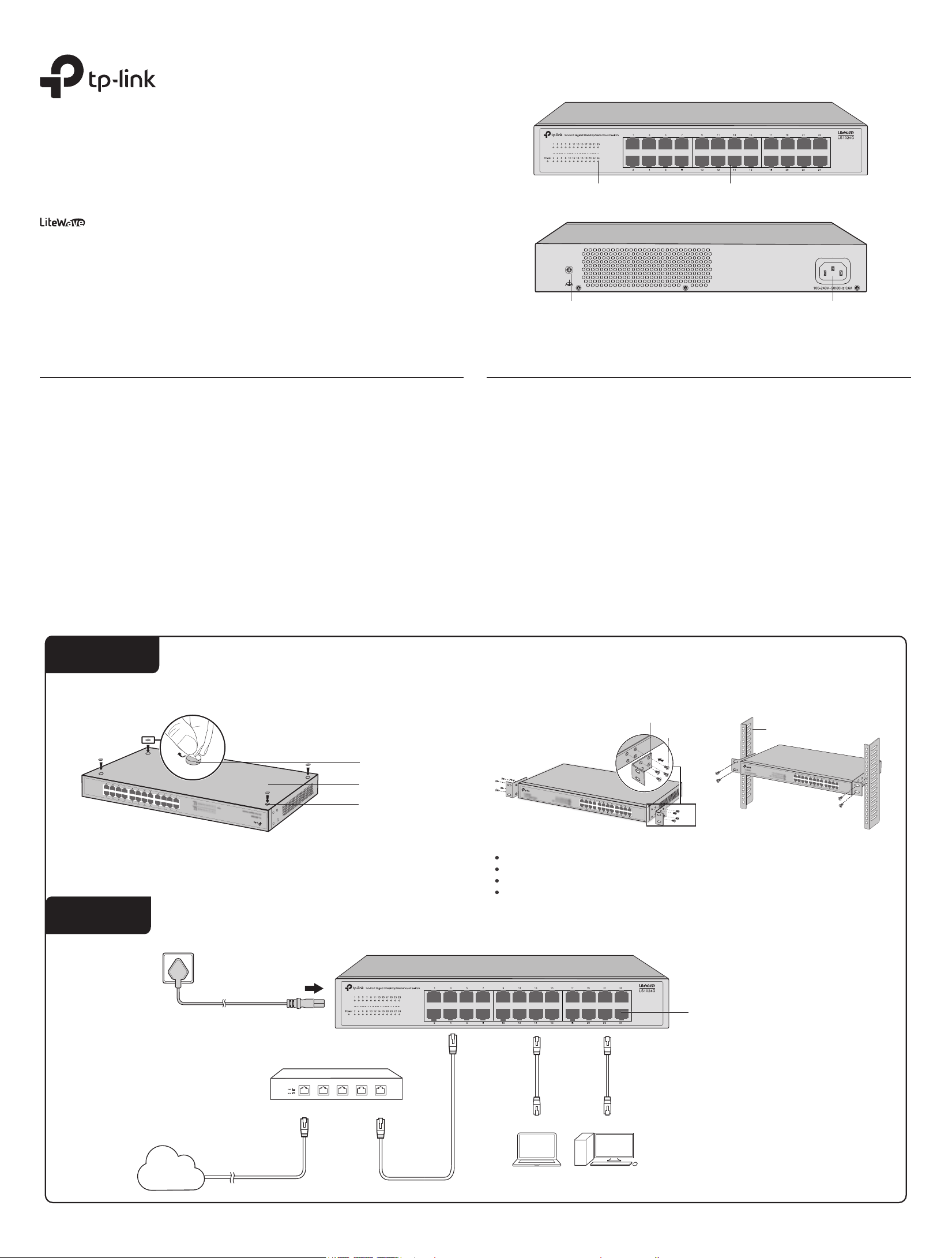
Router/Gateway
LAN PortWAN Port
Internet
AC Power Cord
PC PC
Ethernet Ports
Installation
Connection
Note:
Leave 5 to 10 cm gaps around the devices for air circulation.
Avoid placing heavy things on the device.
Place the device with its bottom facing downwards.
Mount devices in sequence from the bottom to top of the rack and ensure a certain clearance
between devices for the purpose of heat dissipation.
1) Remove the adhesive backing papers from the feet.
2) Attach the feet to the bottom of the switch to prevent it from slipping when placed on a desktop.
Installation Guide
16/24-Port Gigabit Desktop/Rackmount Switch
LS1016G/LS1024G
10/100/1000 Mbps RJ45 Ports
LEDs
Grounding TerminalGrounding Terminal Power Socket
General Specications
Specications
IEEE 802.3, IEEE 802.3i, IEEE 802.3u, IEEE 802.3ab, IEEE 802.3x, IEEE802.1p
CSMA/CD
16/24 10/100/1000 Mbps RJ45 Ports
Auto-Negotiation/Auto MDI/MDIX
10Base-T:
2-pair UTP/STP of Cat. 3 or above (maximum 100 m)
100Base-TX:
2-pair UTP/STP of Cat. 5 or above (maximum 100 m)
1000Base-T:
4-pair UTP/STP of Cat. 5e or above (maximum 100 m)
LS1016G: 32 Gbps
LS1024G: 48 Gbps
Store-and-Forward
Automatically learning, automatically aging
10Base-T: 14881 pps/Port
100Base-X: 148810 pps/Port
1000Base-T: 1488095 pps/Port
To avoid any device damage and bodily injury caused by improper use, you should observe the following rules.
Keep the power o during the installation.
Wear an ESD-preventive wrist strap, and make sure that the wrist strap has a good skin contact and is well
grounded.
Use only the power cord provided with the switch.
Make sure that the supply voltage matches the specications indicated on the rear panel of the switch.
Ensure that the switch is installed in a well-ventilated environment and its ventilation hole is not blocked.
Do not open or remove the cover of the switch.
Before cleaning the device, cut o the power supply. Do not clean it by the waterish cloth, and never use any
other liquid cleaning method.
Place the device with its bottom surface downward.
Safety Precautions
Lightning Protection
Site Requirements
Temperature/Humidity
Installation Site
Extremely high voltage currents can be produced instantly when lightning occurs and the air in the electric
discharge path can be instantly heated up to 20,000 °C. As this instant current is strong enough to damage
electronic devices, more eective lightning protection measures should be taken. Ensure that the rack and
the device are well earthed.
Make sure the power socket has a good contact with the ground.
Keep a reasonable cabling system and avoid induced lightning.
Use the signal SPD (Surge Protective Device) when wiring outdoor.
Note:
For detailed lightning protection measures, refer to the Lightning Protection Guide:
https://www.tp-link.com/us/conguration-guides/lightning_protection_guide
When installing the device on a rack or a at workbench, attach much importance to the following
items:
The rack or workbench is at, stable, and sturdy enough to support the weight of 5.5 kg at least.
The rack or workbench has a good ventilation system. The equipment room is well ventilated.
The rack is well grounded. Keep the device less than 1.5 meters away from the power socket.
Electronic elements including capacitance and inductance on the device can be aected by external
interferences, such as conducted emission by capacitance coupling, inductance coupling, and impedance
coupling. To decrease the interferences, make sure to take the following measures:
Use the power supply that can eectively lter interference from the power grid.
Keep the device far from high-frequency and strong-current devices such as radio transmitting station.
Use electromagnetic shielding when necessary.
Electromagnetic Interference
Keep the equipment room at an appropriate level of temperature and humidity. Too much or too little
humidity may lead to bad insulation, leakage of electricity, mechanical property changes, and corrosion.
High temperatures may accelerate aging of the insulation materials, signicantly shortening the service life
of the device. To nd out the best temperature and humidity conditions for the device, check the following
table.
Transfer Method
Standard
Network Media (Cable)
Interface
Switching Capacity
Protocol
Frame Forwarding Rate
MAC Address Learning
For technical support and other information, please visit
https://www.tp-link.com/support/?type=smb, or simply scan the QR code.
To ask questions, find answers, and communicate with TP-Link users or
engineers, please join TP-Link Community.
The dust accumulated on the switch can be absorbed by static electricity and result in poor contact of
metal contact points. Some measures have been taken for the device to prevent static electricity, but too
strong static electricity can cause deadly damage to the electronic elements on the internal circuit board.
To avoid the eect of static electricity on the operation of the switch, attach much importance to the
following items:
Dust the device regularly, and keep the indoor air clean.
Keep the device well grounded and ensure that the static electricity has been transferred.
Clearness
Q1. The Power LED is not lit.
Q2. The Link/Act LED is not lit when a device is connected to the
corresponding port.
Frequently Asked Questions (FAQ)
The Power LED should be lit when the power system is working normally. If the Power LED is not lit, check as
follows:
A1:
Make sure the power adapter is connected to the switch with power source properly.
A2:
Make sure the voltage of the power supply meets the requirements of the input voltage of the switch.
A3:
Make sure the power source is ON.
It is recommended that you check the following items:
A1:
Make sure that the cable connectors are rmly plugged into the switch and the device.
A2:
Make sure the connected device is turned on and works normally.
A3:
The cable must be less than 100 meters long (328 feet).
Q3. Why does the switch fail to detect and block a loop from occurring in
the network topology when Loop Prevention is enabled?
A:
When this switch is connected to other non-terminal devices, such as switches of other brands, and the
device is incapable of correctly processing or forwarding loop detection packets, the Loop Prevention
function will be limited. It is recommended to connect the terminal devices directly to this switch or
connect non-terminal devices with complete forwarding capability to this switch.
Environmental and Physical Specications
FCC, CE, RoHS
0˚C to 50˚C (32˚F to 122˚F) (For LS1016G)
0˚C to 45˚C (32˚F to 113˚F) (For LS1024G)
-40˚C to 70˚C (-40˚F to 158˚F)
10% to 90%RH non-condensing
5% to 90%RH non-condensing
Certication
Operating Temperature
Storage Temperature
Operating Humidity
Storage Humidity
Environment Temperature Humidity
Operating 0 °C to 50 °C (For LS1016G)
0 °C to 45 °C (For LS1024G)
10% to 90%RH Non-condensing
Storage -40 °C to 70 °C 5% to 90%RH Non-condensing
TP-Link hereby declares that the device is in compliance with the essential requirements and other relevant provisions of
directives 2014/30/EU, 2014/35/EU, 2011/65/EU and (EU)2015/863.
The original EU declaration of conformity may be found at https://www.tp-link.com/en/ce.
EU declaration of conformity
TP-Link hereby declares that the device is in compliance with the essential requirements and other relevant provisions of
the Electromagnetic Compatibility Regulations 2016 and Electrical Equipment (Safety) Regulations 2016.
The original UK declaration of conformity may be found at https://www.tp-link.com/support/ukca/
UK declaration of conformity
Safety Information
Keep the device away from water, re, humidity or hot environments.
Do not attempt to disassemble, repair, or modify the device. If you need service, please contact us.
Place the device with its bottom surface downward.
The plug on the power supply cord is used as the disconnect device, the socket-outlet shall be easily accessible.
The socket-outlet shall be installed near the equipment and shall be easily accessible
Plug the product into the wall outlets with earthing connection through the power supply cord.
Please read and follow the above safety information when operating the device. We cannot guarantee that no accidents
or damage will occur due to improper use of the device. Please use this product with care and operate at your own risk.