Document # G_GO_OM_CONVENTION_4607458 – 06/21
Installation, Operation and Maintenance Manual
This manual is updated as new information and models are released. Visit our website for the latest manual.
Bring Your Passion to the Surface
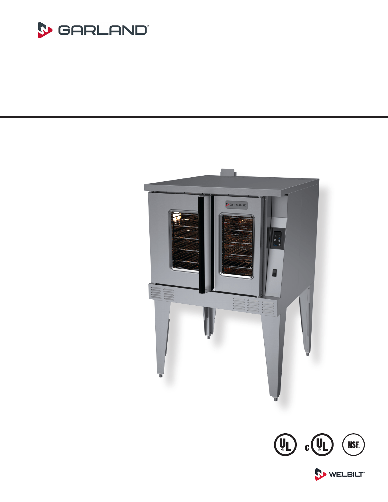
Master Series
Full-Size Gas Convection Ovens
models
MCO-GS-10S
MCO-GD-10S
MCO-GS-20S
MCO-GD-20S
MCO-GS-10M
MCO-GD-10M
MCO-GS-20M
MCO-GD-20M
MCO-GS-10M
Original Document
Users are cautioned that maintenance and repairs must be performed by a Garland authorized service agent
using genuine Garland replacement parts. Garland will have no obligation with respect to any product that has been
improperly installed, adjusted, operated or not maintained in accordance with national and local codes or installation
instructions provided with the product, or any product that has its serial number defaced, obliterated or removed,
or which has been modified or repaired using unauthorized parts or by unauthorized service agents.
For a list of authorized service agents, please refer to the Garland web site at http://www.garland-group.com.
The information contained herein, (including design and parts specifications), may be superseded and is subject
to change without notice.
FOR YOUR SAFETY:
DO NOT STORE OR USE GASOLINE
OR OTHER FLAMMABLE VAPORS OR
LIQUIDS IN THE VICINITY OF
THIS OR ANY OTHER
APPLIANCE
WARNING:
IMPROPER INSTALLATION, ADJUSTMENT,
ALTERATION, SERVICE OR MAINTENANCE
CAN CAUSE PROPERTY DAMAGE, INJURY,
OR DEATH. READ THE INSTALLATION,
OPERATING AND MAINTENANCE
INSTRUCTIONS THOROUGHLY
BEFORE INSTALLING OR
SERVICING THIS EQUIPMENT
PLEASE READ ALL SECTIONS OF THIS MANUAL
AND RETAIN FOR FUTURE REFERENCE.
THIS PRODUCT HAS BEEN CERTIFIED AS
COMMERCIAL COOKING EQUIPMENT AND
MUST BE INSTALLED BY PROFESSIONAL
PERSONNEL AS SPECIFIED.
IN THE COMMONWEALTH OF MASSACHUSETTS
THIS PRODUCT MUST BE INSTALLED BY A
LICENSED PLUMBER OR GAS FITTER. APPROVAL
NUMBER: G-1-07-05-28
For Your Safety:
Post in a prominent location, instructions to be
followed in the event the user smells gas. This
information shall be obtained by consulting
your local gas supplier.
WARNING:
This product contains chemicals known to the State of California to cause cancer and/or birth defects or other
reproductive harm. Installation and servicing of this product could expose you to airborne particles of glass wool/
ceramic fibers. Inhalation of airborne particles of glass wool/ceramic fibers is known to the State of California to cause
cancer. Operation of this product could expose you to carbon monoxide if not adjusted properly. Inhalation of carbon
monoxide is known to the State of California to cause birth defects or other reproductive harm.
Keep appliance area free and clear of combustibles.
Document # G_GO_OM_CONVENTION_4607458 – 06/212
SAFETY NOTICES

CONTENTS
SAFETY NOTICES.......................2
GENERAL INFORMATION ...............5
Model Numbers .............................5
Warranty ....................................5
Serial Plate Location ..........................5
Accessories ..................................5
DIMENSIONS & SPECIFICATIONS ........6
INSTALLATION .........................7
Entry Clearance ..............................7
Installation Clearance ........................7
Installation Of Ovens Equipped With Casters ..7
Installation Of Double Deck Models ...........8
Gas Connection ..............................9
Electrical Connection ........................9
Ventilation & Air Supply ......................9
Installation of a Direct Flue ...................9
Testing & Lighting Instructions ..............10
OPERATING INSTRUCTIONS............11
Master 200 Solid State Control With
Electromechanical Timer ....................11
In O Mode ............................. 11
Start Up................................. 11
Fan Speed .............................. 11
Lights................................... 11
Cool Down.............................. 11
Temperature ............................ 11
Timer ................................... 11
Electronic Control ...........................12
Start Up................................. 12
Manual Mode ........................... 13
Operating the Controls .................. 14
Cook-N-Hold Operation ................. 14
Settings Mode .......................... 14
Cleaning Mode.......................... 14
PERFORMANCE RECOMMENDATIONS AND
GENERAL SAFETY PRECAUTIONS.......15
PROBLEMS / SOLUTIONS ..............16
COOKING GUIDE ......................17
COOK AND HOLD .....................18
CLEANING & MAINTENANCE ...........19
Break-In Period .......................... 19
Exterior Cleaning ........................ 19
Interior Cleaning ........................ 19
Fan Area Maintenance ................... 19
Motor Care.............................. 19
Document # G_GO_OM_CONVENTION_4607458 – 06/21 3

THIS PAGE INTENTIONALLY LEFT BLANK
GENERAL INFORMATION
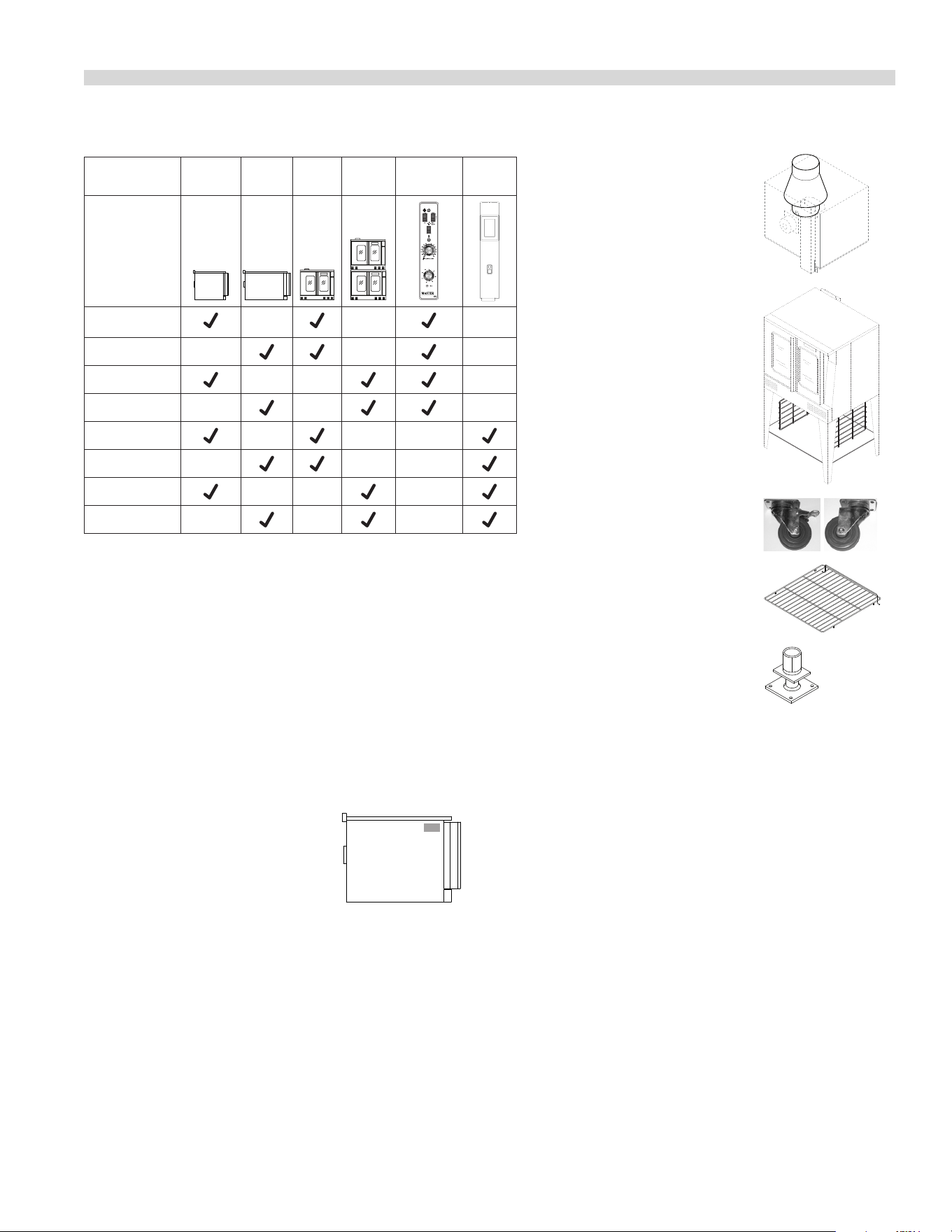
Model Numbers
Model Deep
Depth
Single
Deck
Double
Deck
Master
200
Control
Digital
Control
MCO-GS-10S
MCO-GD-10S
MCO-GS-20S
MCO-GD-20S
MCO-GS-10M
MCO-GD-10M
MCO-GS-20M
MCO-GD-20M
Warranty
Visit www.Garland-Group.com to view or download a copy of your
warranty.
Serial Plate Location
When corresponding with the factory or your local authorized
factory service center regarding service problems or replacement
parts, be sure to refer to the particular unit by the correct model
number (including the prefix and suffix letters and numbers) and
the warranty serial number.
• The serial plate is affixed to the
upper right corner of the left
body panel.
Accessories
• Direct Connect Vent
• Stainless steel open base
with rack guides and shelf
(in lieu of 25-inch legs) for
extra rack/pan storage,
single deck oven only
• Casters (set of 4) with front
brakes
• Extra oven rack
• Deck fasteners for stainless
steel flanged feet
• Gas flex hose and quick disconnect (3/4-inch NPT
x 5-feet) with restraining device
• Removable stainless steel drip pan
Document # G_GO_OM_CONVENTION_4607458 – 06/21 5
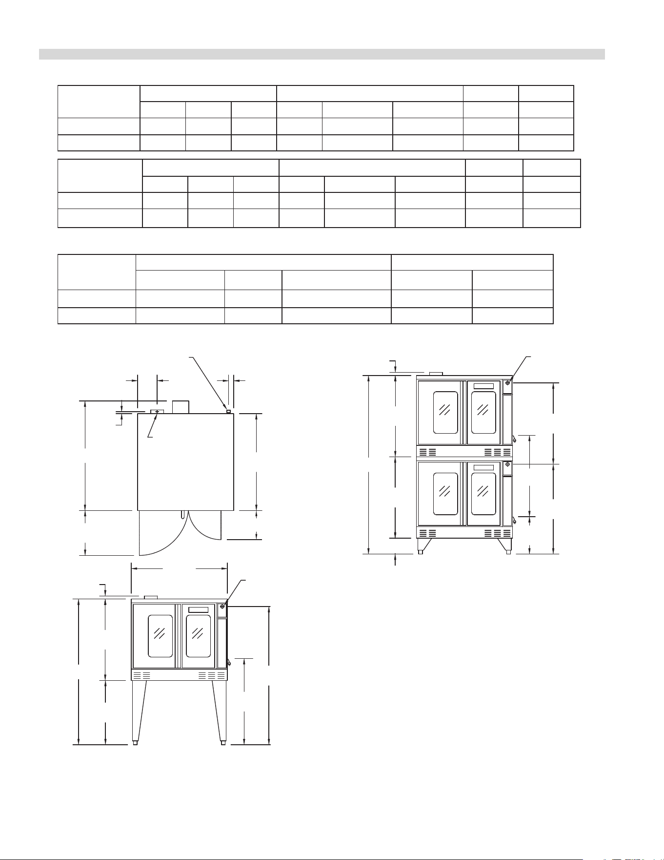
Gas Input ratings shown here are for installations up to 2,000-ft. (610m) above sea level. Specify altitudes over 2,000 ft.
Commercial cooking equipment requires an adequate ventilation system. For additional information, refer to the National Fire Protection
Association’s standard NFPA96, “Vapor Removal from Cooking Equipment.” (NOTE: For North America only)
Please specify gas type when ordering.
7-3/4"
[197mm]
38-1/4"
[972mm]
3/4"
[19mm]
17-3/4"
[451mm]
TOP VIEW
2"
[51mm]
FLUE: 2-3/8" x 5"
[60mm x 127mm]
3/4" N.PT.
GAS INLET
11-1/2"
[292mm]
38"
[965mm]
32-1/8"
[816mm]
25-3/8"
[645mm]
SINGLE DECK
FR ONT VIEW
1-1/4"
[32mm]
34"
[864mm]
54-9/16"
[1386mm]
3/4" REAR
GAS INLET
32-1/8"
[816mm]
32-1/8"
[816mm]
6-1/4"
[159mm]
14-3/4"
[375mm]
32-1/8"
[816mm]
35-7/16”
[900mm]
32-1/8"
[816mm]
1-1/4"
[32mm]
DOUBLE DECK
FR ONT VIEW
D
H
H
1" REAR
GAS INLET
Single-Deck
Models
Int. Dimensions :In (mm) Ext. Dimensions: In (mm) Ship Wt Ship Dim.
W H D W H * D Lbs/kg Cubic Ft.
Standard Depth 29 (736) 24 (610) 24 (610) 38 (965) 57-1/2 (1461) 41-1/4(1048) 515/230 64
Deep Depth 29 (736) 24 (610) 28 (711) 38 (965) 57-1/2 (1461) 44-1/2(1130) 545/245 64
Double-Deck
Models
Int. Dimensions: In (mm) Ext. Dimensions: In (mm) Ship Wt. Ship Dim.
W H D W H * D 2@Lbs/kg Cubic Ft.
Standard Depth 29 (736) 24 (610) 24 (610) 38 (965) 70-1/2 (1791) 41-1/4(1048) 1030/465 128
Deep Depth 29 (736) 24 (610) 28 (711) 38 (965) 70-1/2 (1791) 44-1/2(1130) 1090/490 128
* Height with legs or with standard casters. Height with low profile casters (double deck) is 68-1/2” (1740mm).
Models
Input Ratings, Nat & Pro Electrical Specifications
BTU/hr kW Equiv. Gas Inlet 120V/1Ph. 240V/1Ph.
Single Deck 60,000 /80,000* 17. 6 /23.4* (1 )@ 3/4" NPT (1)@9.8A (1)@ 5.2A
Double Deck
120,000 /160,000*
35.2/46.9* (1 )@1" NPT
(2)@9.8A (2)@ 5.2A
Operating Pressure:
Natural: 4" WC (10 mbar)
Propane: 10" WC (25 mbar)
Max 13.8" WC @ 70°F (21°C)
NOTE: Data applies only to
North America
Notes:
1. Standard electrical specications include motor requirements.
2. (120V units) 115V 0.6 HP, 2-speed motor; 1430 and 1670 rpm 60Hz
3. (240V units) 200-240V, 0.6 HP, 2-speed motor; 1430 and 1670 rpm, 60Hz
4. A 6 ft. line cord is provided for each 120V deck with a (NEMA #5-15P) plug.
5. Garland recommends a separate 15 AMP circuit for each 120V unit.
(includes
fan motor)
DIMENSIONS & SPECIFICATIONS
*Optional burner imput rating for natural gas only.
Document # G_GO_OM_CONVENTION_4607458 – 06/216
Entry Clearance
• Crated: 47" (1194mm)
• Uncrated: 32-1/2" (826mm)
Installation Clearance
NOTE: Always provide adequate clearance for maintenance
and operation.
• Installation adjacent to combustible and non-
combustible wall, minimum clearance:
Left Side Control Side Rear
Single-Deck 1" (26 mm) 1" (26 mm) 3" (77 mm)
Double-Deck 1" (26 mm) 2" (51 mm) 3" (77 mm)
• Installation near high heat producing equipment,
minimum clearance:
Left Side Control Side Rear
Single-Deck 1" (26 mm) 6" (153 mm) 3" (77 mm)
Double-Deck 1" (26 mm) 6" (153 mm) 3" (77 mm)
Notice
Avoid installing ovens near equipment, such as char-
broilers or fryers, which generate high heat and high
grease laden air.
• Clearance for Service (recommendation):
Control Side, minimum
Single-Deck 12" (305 mm)
Double-Deck 12" (305 mm)
NOTE: Install units with casters in very tight
locations for ease of service.
The importance of the proper installation of Commercial
Gas Cooking Equipment cannot be over stressed. Proper
performance of the equipment is dependent, in great part,
on the compliance of the installation with the manufacturer's
specications. Installation must conform to local codes or, in
the absence of local codes, with the National Fuel Code, ANSI
Z223.1, Natural Gas Installation Code, CAN/CGA-B149.1, or the
Propane Installation Code, CAN/CGA-B149.2, as applicable.
Before assembly and connection, check gas supply.
A. The type of gas for which the unit is equipped is stamped
on the data plate located on the upper right corner of
the left body side panel. Connect a unit stamped "NAT"
only to natural gas; connect a unit stamped "PRO" only to
propane.
B. If it is a new installation, have gas authorities check meter
size and piping to assure that the unit is supplied with
sucient amount of gas pressure required to operate the
unit.
C. If it is additional or replacement equipment, have gas
authorities check pressure to make certain that existing
meter and piping will supply fuel at the unit with not more
that 1/2" water column pressure drop.
NOTE: When checking pressure be sure that all other
equipment on the same gas line is on. An internal pressure
regulator is supplied with GARLAND Convection Ovens.
Regulator is preset to deliver gas at pressure shown on the
rating plate.
The appliance and its individual shut-o valve must be
disconnected from the gas supply piping system during
any pressure testing of that system at test pressures in
excess of 1/2 PSI (3.45 kPa).
The appliance must be isolated from the gas supply
piping system by closing its individual manual shut-o
valve during any pressure testing of the gas supply piping
system at test pressures equal to or less than 1/2 PSI
(3.45 kPa).
Installation Of Ovens Equipped With Casters
A. For an appliance equipped with casters, the installation
shall be made with a connector that complies with the
Standard for Connectors for Movable Gas Appliances,
ANSI Z21.69 /CSA 6.16, and a quick-disconnect device
that complies with the Standard for Quick-Disconnect
Devices for Use With Gas Fuel Appliances, ANSI Z21.41 /
CSA 6.9, and adequate means must be provided to limit
the movement of the appliance without depending
on the connector and the quick-disconnect device or
its associated piping to limit the appliance movement
and the location(s) where the restraining means may be
attached to the appliance shall be specied.
B. The front casters of the unit are equipped with brakes
to limit the movement of the oven without depending
on the connector and any quick-disconnect device or its
associated piping to limit the appliance movement.
C. The restraint can be attached to the unit near the gas inlet.
If the restraint is disconnected, be sure to reconnect the
restraint after the oven has been returned to its originally
installed position.
INSTALLATION
Document # G_GO_OM_CONVENTION_4607458 – 06/21 7
Installation Of Double Deck Models
A. Position insert in bottom leg opening and tap insert up
into leg till it seats at collar. Attach six inch (6") legs to
lower oven section. Raise unit or lay on its left side. Place
the front legs on the oven so as to line up with four (4)
attaching bolt holes. Secure leg to oven frame using (4)
3/8-16 x 3/4 bolts and washers provided. Repeat at rear of
unit.
B. Remove lower front cover of top deck (located under oven
doors). Raise top deck into place and line up body sides
and back of the unit. Fasten the rear of the units together,
with the stacking bracket, using (6) 1/4-20 machine
screws, lock washers and nuts, (provided).
C. Install the interconnecting ue parts, carefully following
the instructions contained in the stacking kit. Pay
particular attention to the type of ovens you are stacking
and be sure to follow the corresponding instructions.
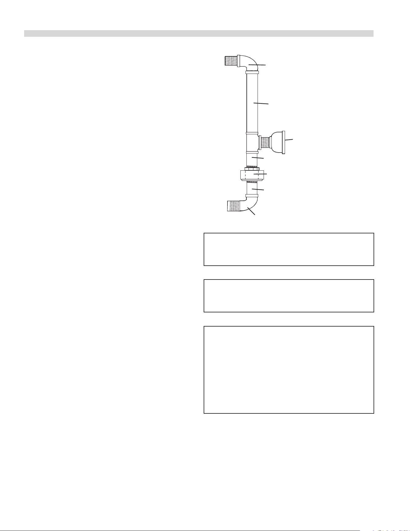
D. Assemble the stacking pipes provided in the stacking kit
as shown in the diagram on this page. This allows both
ovens to be supplied by a single gas line. The minimum
recommended size of a single supply line for two stacked
ovens is 1 inch. Use a pipe thread compound that is
intended for use on propane gas piping and be sure to
check for leaks before nalizing the installation.
E. Check leveling of unit four (4) ways (using a common
carpenter's level on the rack inside the oven).
F. Plug the cord set of each unit into a 115-Volt power supply
outlet.
G. Maintain clearance from combustibles.
Each gas appliance shall be located with respect to building
construction and other equipment so as to permit access to
the appliance. Such access and clearance may be necessary
for servicing and cleaning.
INSTALLATION Continued
3/4" Union
3" Nipple
3" Nipple
90 Degree Street Elbow
90 Degree Street Elbow
20-1/2" Nipple
3/4" to 1" Bell Reducer
CAUTION:
DISCONNECT BOTH UNITS FROM
ELECTRICAL SUPPLY BEFORE SERVICING.
POWER FAILURE
In the event of a power failure, no attempt should be
made to operate this oven.
IMPORTANT
All gas burners and pilots need sufficient air
to operate and large objects should not be placed in
front of this oven, which would
obstruct the airflow through the front.
Objects should not be placed on main top
rear of oven while in use. This could obstruct the venting
system of the unit's flue products.
Document # G_GO_OM_CONVENTION_4607458 – 06/218
Gas Connection
The 1" NPT inlet at the rear must be considered in piping the
gas supply for double stack units or ¾" NPT for individual (or
single deck) connections. Undersized gas supply line(s) may
restrict the gas supply and aect performance. If other gas
appliances are supplied by the same supply line, the supply
line must be sized to carry the combined volume without
causing more than 1/2" pressure drop at the manifold of each
appliance on the line at full rate.
Recommended supply pressures are 7" WC, (NAT), and
11" WC, (PRO); ± 5%. (Must not exceed 13.8" WC [NAT], and
15" WC [PRO]).
Electrical Connection
A 15 AMP service must be provided for each oven. For 115
VAC usage, a cord and plug (NEMA #5-15P) is provided but
connection to the electrical service must be electrically
grounded in accordance with local codes, or in the absence of
local codes, with the National Electrical Code, ANSI/NFPA 70,
or the Canadian Electrical Code, CSA C22.2, as applicable.
This appliance is equipped with a three-prong (grounding)
plug for your protection against shock hazard and should
be plugged directly into a properly grounded three-prong
receptacle.
DO NOT CUT OR REMOVE THE
GROUNDING PRONG FROM THIS PLUG.
A wire diagram is axed to the rear of the unit.
Ventilation & Air Supply
Proper ventilation is highly important for good operation.
There are only two choices for properly venting an oven: 1)
canopy hood style or 2) direct venting. The ideal method
of venting a GAS Convection Oven is through the use of a
properly designed canopy, which should extend 6" (150 mm),
beyond all sides of the appliance and 6'6" (1950 mm) from the
oor.
A strong exhaust fan will create a vacuum in the room. For an
exhaust system vent to work properly, exhaust and make-up
air must be balanced properly. For proper air balance contact
your local H.V.A.C. contractor.
All gas burners and pilots need sucient air to operate and
large objects should not be placed in front of this oven, which
would obstruct the airow through the front.
INSTALLATION Continued
Installation of a Direct Flue
When the installation of a canopy type exhaust hood is
impossible the oven may be direct vented. Before direct
venting check your local codes on ventilation, in the absence
of local codes, refer to the National Fuel Code NFPA 54, ANSI
Z223.1 (latest revision).
If the unit is to be connected directly to a direct ue, it is
necessary that draft diverter be installed to insure proper
ventilation.
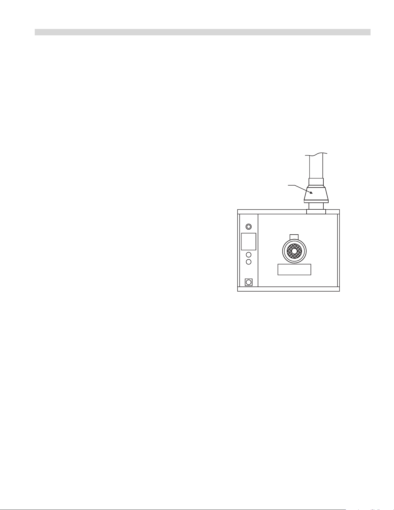
DRAFT DIVERTER
Direct venting, should be positioned on the main top and
fastened with sheet metal screws provided.
NOTE: Each oven has been factory tested and adjusted prior
to shipment. It may be necessary to further adjust the oven
as part of a proper installation. Such adjustments are the
responsibility of the installer. Adjustments are not considered
defects in material and workmanship, and they are not
covered under the original equipment warranty.
DO NOT UNDER SIZE VENT PIPE!
This can cause resistance to ow and impede good venting.
We suggest that if a horizontal run must be used it should
rise no less than 1/4" (6.25mm) for each linear foot of run, and
after a total of 180° of bends you should increase the size of
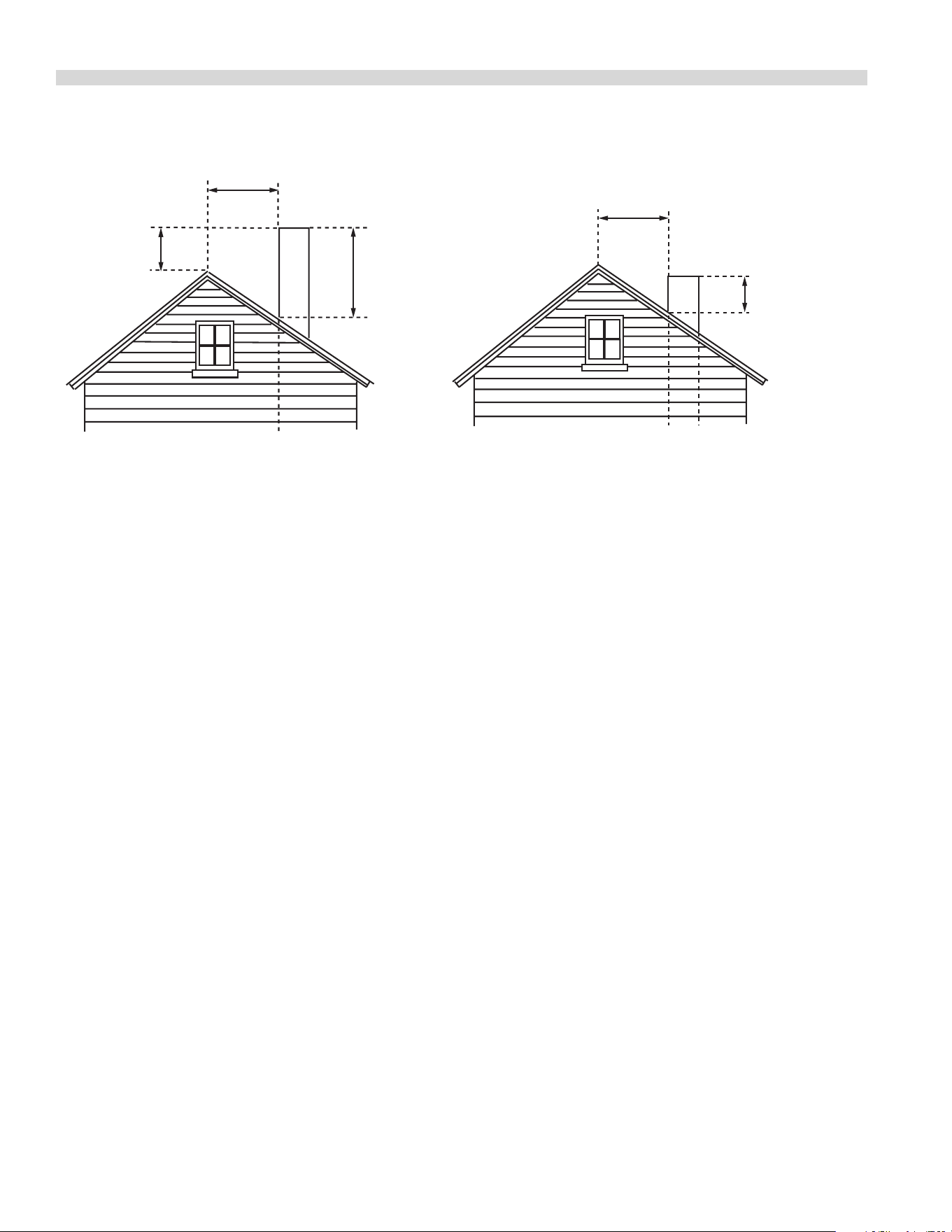
stove pipe by two (2") inches. The ue should rise 2' (60cm) to
3' (90cm) above the rooine or 2' (60cm) to 3' (90cm) above
any portion of a building within a horizontal distance of 10
(3 meters) feet.
The following diagram is only one example from the National
Fuel Gas Code Book NFPA 54, ANSI Z223.1, 7.5.3:
Document # G_GO_OM_CONVENTION_4607458 – 06/21 9
Termination Less than 10 feet (3 meters) from ridge Termination More than 10 feet (3 meters) from ridge
Less than 10 feet (3 meters)
More than 10' (3 meters)
2' (60cm)
Min.
3' (90cm) Min.
3' (90cm) Min.
INSTALLATION continued
Testing & Lighting Instructions
1. Turn on main gas valve. Remove the lower front cover
and the service panel above the control panel. Drop the
control panel and leak test all ttings and connections
upstream from the service valve located on the redundant
combination gas valve. Should any gas leaks be detected,
turn OFF main gas valve, correct the problem and retest.
2. Open shuto valve located on the redundant combination
gas valve. Activate control panel and set to desired
temperature. The pilot burner is ignited by direct spark,
main burners are then ignited by the pilot. Check all
ttings again and correct any leaks and recheck.
Replace all service panels and covers before operation.
NOTE: All electronic ignition systems are supplied with a
redundant gas valve. Therefore, the unit is not supplied with
an external pressure regulator.
NOTE: During installation there will be air in the gas line. This
air will have to bleed o before ignition can be established.
The electronic ignition system has a ninety second lock-out
as a safety device on all units. Therefore, several attempts
may be required before pilot ignition is established, wait ve
minutes after each attempt.
FOR YOUR SAFETY: KEEP YOUR APPLIANCE AREA FREE FROM
COMBUSTIBLES.
TO CONSERVE ENERGY:
Do not waste energy by leaving controls at high temperature
settings during idle periods. Lower settings will keep
oven warm and ready for next use period. Master 400
Series controls have an auto setback feature that is user
programmable to help with these applications.
Document # G_GO_OM_CONVENTION_4607458 – 06/2110
Master 200 Solid State Control With
Electromechanical Timer
In O Mode
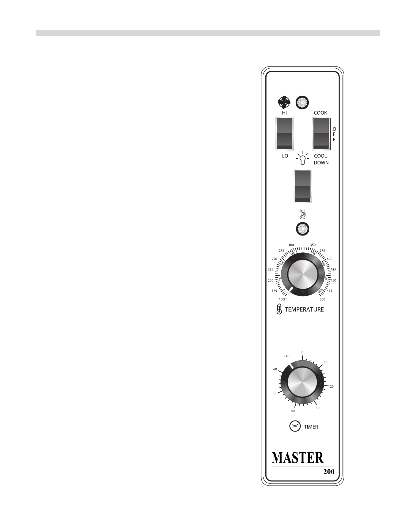
When the oven is o, there are no lights or indicators.
Start Up
Press the Cook/O/Cool Down rocker switch to the “Cook” position.
The green lamp will light indicating the oven is powered in cook
mode.
The oven will begin to heat to the temperature set on the thermostat
dial. The amber lamp will light indicating the heat is active. As the
heat cycles on and o to maintain the set temperature this light will
go on and o accordingly.
The door must be closed for the oven to operate in cook mode.
Opening the door will cause the heat to stop. The motor and fan will
shut o. This is a safety feature.
Fan Speed
The fan speed can be either high (1670 RPM) or low (1430 RPM). The
fan speed is controlled by the left rocker switch marked high and low.
Lights
The oven lights are activated by pressing the light switch on the
control panel. This is a momentary switch and the lights will stay
lit as long as this button is held in the on position. Lights will work
whenever there is electrical power connected to the oven.
Cool Down
Pressing the Cook/O/Cool Down rocker switch to the Cool Down
position activates the fan and motor to cool the oven cavity. The door
must be open slightly for the fan and motor to start. The heat is not
active in this mode.
Optimal cool down will be achieved with the door open slightly.
Opening the door too far will shut the fan and motor o. This is a
patented safety feature.
Pressing the button to the OFF position cancels the cool down and
turns the oven o.
Temperature
The temperature range is from 150°F to 500°F (66°C to 260°C) is
controlled by rotating the temperature dial and aligning the
indicator to the desired temperature.
Timer
The timer is set by rotating the dial clockwise aligning the indicator to
the desired time cycle. The timer will count down from 2 minutes to
60 minutes. At the end of the timing cycle the buzzer will sound. The
buzzer is turned o by rotating the dial counter clockwise to the o
position,
NOTE: The timer does not control heating
OPERATING INSTRUCTIONS
Document # G_GO_OM_CONVENTION_4607458 – 06/21 11
OPERATING INSTRUCTIONS Continued
Electronic Control
Start Up
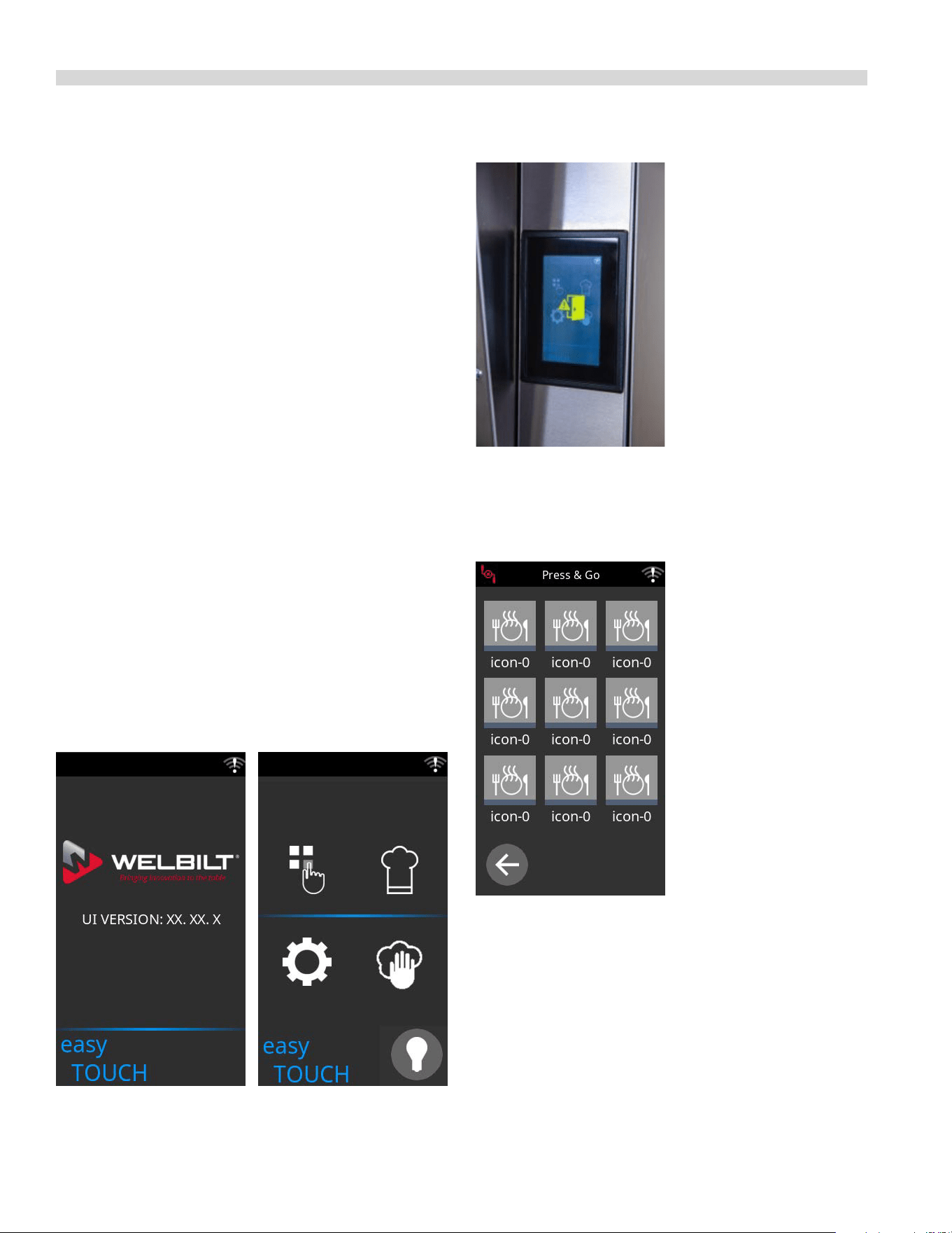
When the controller is o the display will be blank. Pressing
the main power switch ON will activate the controller and
the splash screen (photo 1) displaying the software version
and then the home screen (photo 2), will appear on the user
interface. The home screen displays the four main icons of
the control - the Press and Go Menu (square pattern) in
the upper left, Settings Mode (gear cog) in the lower left,
Manual Mode (chef’s hat) in the upper right and the Pause
for Cleaning (hand and cloth) button in the lower right.
Note that If the door is opened during a cooking mode, the
fan and heat will stop, the interior light comes on, the control
will pause and the display will indicate door is open symbol
(see photo 3) until the door is closed. This is a patented
safety feature. This period of pause allows time for removing
product and restarting the cook cycle.
If one opens the door slightly for more than three seconds
the oven will enter a Cool Down mode and deactivate
the heat and turn the fan on high until the oven cavity
temperature drops below 150°F (66°C). The Cool down
will operate when the door is opened slightly (at least ve
degrees). Optimal cool-down will be achieved with the door
open slightly. When the door opens wider, the Cool Down
mode will deactivate and the display will indicate Door Open
(Photo 3). This is a patented safety feature. Cool Down is not
active during a cook cycle.
Press and Go Menu (square pattern)
Allows quick access to existing recipes (see photo 7).
Photo 1 Photo 2
Photo 3
Photo 7
One need only select the desired icon.
Document # G_GO_OM_CONVENTION_4607458 – 06/2112
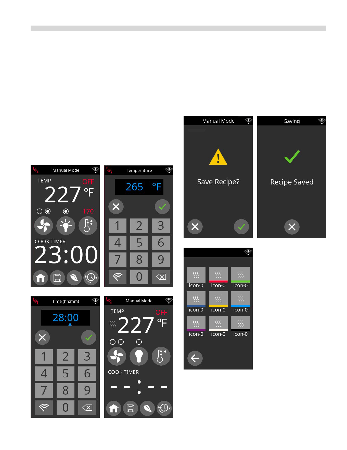
OPERATING INSTRUCTIONS Continued
Manual Mode (chef’s hat)
-Cook temperature (photo 5)
-Low or high fan speed or fan pulse mode whereby the fan
will pulse on and o when the oven is in holding mode.
(fan symbol photo 4 and 8)
-Set main cook timer (24 hour timer) (photo 8)
-Set secondary cook timer (24 hour timer) to allow for
dierent cook times for dierent rack positions (photo 6)
-Turn interior light on/o (light symbol photo 4 and 8)
-Select Cook & Hold temperature (temperature appears in
red -see photo 4)
Photo 4
Photo 13
Photo 6
Photo 5
Photo 14
Photo 8
Photo 15
Manual Mode cont’d.
-Program/Save recipes (photo 13 and 14)
-Select one of nine default recipes (photo 15)
-Change icons and colour (photo 15)
Document # G_GO_OM_CONVENTION_4607458 – 06/21 13
OPERATING INSTRUCTIONS Continued
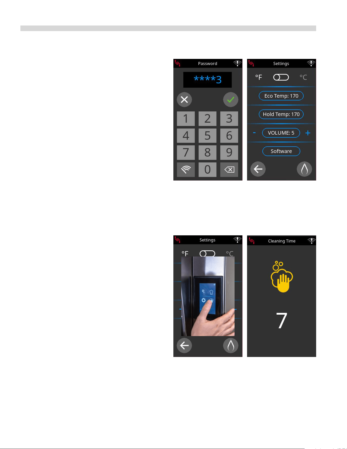
CLEANING MODE (Hand & Cloth - photo 11)
-In the cleaning mode the screen remains frozen for seven
seconds to allow for cleaning between operators
(see photo 12)
Operating the Controls
Setting the cook temperature (from 150 deg. F to 500 deg.
F (65 deg. C to 260 deg. C)) and time are done in the same
manner (see photos 5 and 6).
When the timing cycle is started the display will count down
from the Set time in minutes and seconds. Note that an
alarm will sound when the set point temperature is reached
and the cook time is completed.
Cook-N-Hold Operation
Pressing the Cook-N-Hold symbol (see photo 4 -
thermometer symbol next to light bulb) activates the Cook-
N-Hold mode The display will show the hold temperature in
red. At the end of the cook cycle, an audible alarm will sound
and the display will change to count “up” the time the oven
is on hold. The oven will switch to the programmed hold
temperature. The timer will sound the alarm again after the
hold time has elapsed.
Setting the cook temperature, hold temperature and time
are done in the same manner (see photos 5 and 6). The
desired temperature is shown on the display.
Pressing the enter symbol will start the timing cycle.
Settings Mode (Gear Wheel)
-To enter the Settings screen a password must be keyed in
from the key pad (see photo 9). The Settings Mode allows
one to (see photo 10):
-Select deg. F or deg. C
-Select ECO Mode Temperature
-Select Cook & Hold Temperature
-Select Alarm Volume
-Perform software updates via USB (accessibility to
technicians only)
Photo 9 Photo 10
Photo 11 Photo 12
Document # G_GO_OM_CONVENTION_4607458 – 06/2114

1. Preheat oven thoroughly (approx. 20 minutes) before use.
2. As a general rule, temperature should be reduced 25°
to 50° from that used in a standard/conventional oven.
Cooking time may also be shorter, so we suggest closely
checking the rst batch of each product prepared.
3. Use the chart of suggested times and temperatures as
a guide. These will vary depending upon such factors
as size of load, temperature, and mixture of product
(particularly moisture) and density of product.
4. Keep a record of the times, temperature, and load sizes
you establish for various products. Once you have
determined these, they will be similar for succeeding
loads.
5. When practical, start cooking the lowest temperature
product rst and gradually work up to higher
temperatures.
6. If you nd that your previous temperature setting is more
than 10° higher than needed for succeeding loads, COOL
DOWN to reach the desired temperature before setting a
new cooking temperature.
7. When loading oven, work as quickly as possible to
prevent loss of heat.
8. Oven will continue to heat even though the timer goes
o. Product should be removed from the oven as soon as
possible to avoid over cooking.
9. Center pans on racks and load each shelf evenly to allow
for proper air circulation within the cavity.
10. When baking, weigh or measure the product in each pan
to assure even cooking.
11. When cooking six pans, use rack positions 1, 4, 6,8,10 and
12, starting from the top.
12. Do not overload the oven. Six pans are suggested for
most items, i.e., cakes, cookies, rolls, etc. However, the
maximum (13 pans) may be used for sh sticks, chicken
nuggets and hamburgers. Cooking times will have to be
adjusted.
13. Mun pans should be placed in the oven back to front
or with the short side of the pans facing the front. This
results in the most evenly baked product.
14. When re-thermalizing frozen casseroles, preheat the oven
100° over the suggested temperature. Return to cooking
temperature when the oven is loaded. This will help
compensate for the introduction of a large frozen mass
into the cavity.
15. Use pan extenders or two inch deep 18” x 26” pans for
batter type products which weigh more than eight
pounds, i.e., Pineapple Upside down Cake.
16. Never place anything directly on the bottom of the oven
cavity. This obstructs the airow and will cause uneven
results.
17. Never operate the oven if any of the exterior covers are
removed. These covers are necessary for protection
against exposure to live electrical parts and should
only be removed when the oven is being serviced by a
qualied service personnel.
18. This is a commercial cooking oven not intended for non
commercial cooking installations or non food products.
19. Use appropriate food pans and trays for ovens.
20. Use oven mitts when adding or removing trays/pans from
oven when oven is operational.
21. Use care when removing product from the oven to
prevent spills which could cause serious inquiry to bare
skin and eyes. Higher rack levels on ovens are at eye level.
22. Exterior oven exteriors will become hot during operation
caution should be observed.
23. Proper weight handling and distribution of product in
tray or pan will prevent sudden shifts in product to avoid
spills and inquiry.
24. Do not operate ovens blower fan guard has been
removed.
25. Oven operation sound pressure level should not exceed
70 dB(A).
Note: Moisture will escape around the doors when baking
products with heavy moisture content, such as chicken,
potatoes, etc. This is normal.
PERFORMANCE RECOMMENDATIONS AND GENERAL SAFETY
PRECAUTIONS
Document # G_GO_OM_CONVENTION_4607458 – 06/21 15
PROBLEM/SOLUTIONS
Problem Solution
Cakes are dark on the sides and not done in the center Lower oven temperature
Cakes edges are too brown Reduce number of pans or lower oven temperature
Cakes have light outer color Raise temperature
Cake settles slightly in the center Bake longer or raise oven temperature slightly.
Do not open doors too often or for long periods
Cake ripples Overloading pans or batter is too thin
Cakes are too coarse Lower oven Temperature
Pies have uneven color Reduce number of pies per rack
or eliminate use of bake pans
Cupcakes crack on top Lower oven temperature
Meats are browned and not done in center Lower temperature and roast longer.
Meats are well done and browned Reduce time. Limit amount of moisture
Meats develop hard crust Reduce temperature or place pan of water in oven.
Rolls have uneven color Reduce number or size of pans.
Document # G_GO_OM_CONVENTION_4607458 – 06/2116
The following suggested times and temperatures are provided as a starting guide. Elevation, atmospheric conditions, gas
supply, recipe, cooking pans, and oven loading may aect your actual results.
COOKING GUIDE
Product °F Time
White Sheet Cakes – 5 lb 300° 20 min
White Sheet Cakes – 6 lb 300° 22 min
Yellow Layer Cake – 21 oz 325° 15 min
Yellow Sheet Cake – 5 lb 300° 22 min
Chocolate Layer Cake – 21 oz 300° 22 min
Angel Food Cake 375° 22 min
Brownies 350° 15 min
Product °F Time
Chicken Parts 350° 45 min
Hamburger Patties, 10 lb frozen 350° 8 min
Hamburger Patties, 10 lb fresh 350° 5 min
Hamburger Patties, 4 lb fronzen 350° 12 min
Hamburger Patties, 4 lb fresh 350° 8 min
Meatloaf – 4 lb 325° 45 min
Bacon 350° 10 min
Roast Beef - 20 lb 325° 3 hr 15 min
Prime Rib - 10 lb 300° 1 hr 45 min
Stued Pork Chops 350° 45 min
Lamb Chops 375° 40 min
Boneless Veal Roast 300° 3 Hr
Product °F Time
Soda Biscuits 400° 6 min
Yeast Rolls 325° 24 min
Sweet Bread 325° 24 min
Corn Bread 350° 22 min
Gingerbread 300° 24 min
Apple Turnovers 350° 25 min
Cream Pus 300° 25 min
Sugar Cookies 325° 12 min
Chocolate Chip Cookies 375° 8 min
Apple Pie (Fresh) 375° 25 min
Blueberry Pie (Fresh) 350° 30 min
Blueberry Pie (Frozen) 300° 56 min
Pumpkin Pie (Frozen) 300° 50 min
Frozen Pizza 300° 6 min
Macaroni & Cheese 350° 15 min
Fish Sticks 350° 16 min
Stued Peppers 350° 45 min
Baked Potatoes 350° 60 min
Product °F Time Product °F Time
Document # G_GO_OM_CONVENTION_4607458 – 06/21 17
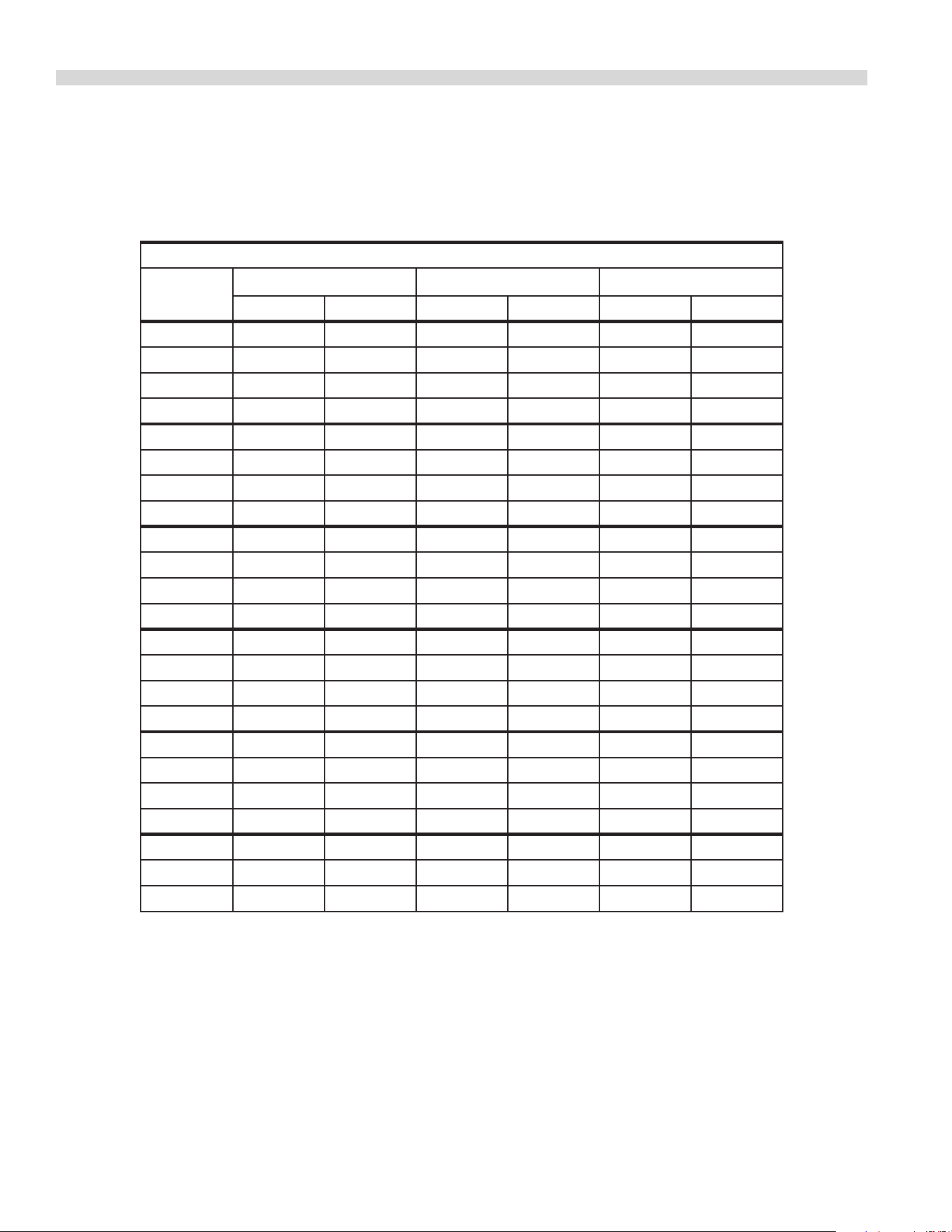
Please refer to the operating instructions for cook and hold feature. The times and temperatures listed below are to be used
as a starting guide. Your actual results may vary greatly depending on your elevation, gas supply, atmospheric conditions and
other items being cooked at the same time.
COOK AND HOLD
Time in Hours
Weight in
lbs
Temperature: 200°F Temperature: 250°F Temperature: 300°F
Rare Medium Rare Medium Rare Medium
8 2.5 3.5 1.5 2 1.25 1.5
9 2.75 3.75 1.75 2.25 1.25 1.75
10 3 4.25 2 2.5 1.5 1.75
11 3.25 4.5 2 2.75 1.5 1.75
12 3.5 5 2.25 3 1.5 2
13 3.75 5 2.5 3.25 1.5 2.25
14 4 5.75 2.5 3.5 1.75 2.5
15 4.25 6 2.75 3.5 2 2.5
16 4.5 6.25 2.75 3.75 2 2.75
17 4.75 6.5 3 4 2.25 2.75
18 4.75 6.75 3.25 4.25 2.25 3
19 5 7.25 3.25 4.25 2.25 3
20 5.25 7.5 3.5 4.5 2.5 3.25
21 5.5 7.75 3.5 4.75 2.75 3.5
22 5.75 7.75 3.5 4.75 2.75 3.5
23 6 8.25 3.75 5 2.75 3.75
24 6 8.75 3.75 5 2.75 3.75
25 6.25 9 4.25 5.5 3 4
26 6.5 9.25 4.25 5.5 3.25 4.25
27 6.75 9.5 4.25 5.75 3.25 4.25
28 7 9.75 4.5 6 3.25 4.25
29 7.25 10 4.75 6.25 3.5 4.5
30 7.25 10.25 4.75 6.25 3.5 4.5
Document # G_GO_OM_CONVENTION_4607458 – 06/2118

CLEANING AND MAINTENANCE
NOTE: Disconnect line cord from power supply before
cleaning or servicing.
Break-In Period
When oven is new, operate it for one hour at 375°F (191°C)
before you begin your normal cooking operation. After
cooling, wipe the interior, including the racks, with a clean
damp cloth.
Exterior Cleaning
Establish a regular schedule. Any spills should be wiped o
immediately.
1. The oven should always be allowed to cool suciently
before any cleaning is attempted.
2. Wipe exposed, cleanable surface when cool with a mild
detergent and hot water. Stubborn residue spots may be
removed with a lightweight non-metallic scouring pad.
Dry thoroughly with a clean cloth.
3. Stubborn stains may be removed by using a non-metallic
abrasive pad, rubbing in the direction of the metal’s grain.
If necessary, for particularly heavy deposits, you may mix
a thin paste of water and scouring powder, and apply
it with a sponge. Be careful to apply light pressure and
remember to rub only in the direction of the grain in the
metal.
4. The control panel surface is easily cleaned with hot water,
soap and a soft cloth. Do not use hard abrasives, solvent
type materials or metallic scouring pads since these will
scratch or cloud the surface.
5. Never spray the perforated areas of the control panel with
steam or water jets, as this allow moisture into the control
cavity. Moisture could damage the electrical components
or place the operator at risk of electrical shock.
Interior Cleaning
Establish a regular cleaning schedule or wipe o on the same
day when spillovers occur.
1. Cool down oven.
2. Remove oven racks.
3. Lift rack guides on either side of oven o of holders. Racks
and guides may be run through dishwasher while oven
cavity is being cleaned.
4. Clean with soap and water using a non-metallic scouring
pad, if necessary. If dirt and grease have accumulated, a
mild ammonia solution or commercial oven cleaner such
as Easy-O or Dow may be used.
5. To reinstall, reverse procedure. Place the bottom of the
rack guide against the cavity wall. Keeping the top pulled
away from the wall lift up. Push the top of the guide
against the wall and push down locking it into place.
Fan Area Maintenance
If aluminum foil is routinely used to wrap food or cooking
vessels during oven operation, the following preventive
maintenance must be performed:
1. Turn power switch to “O” position
2. Remove oven racks and rack guides.
3. Remove air bae and clean any stains or deposits.
4. Check blower wheel and air bae for particles of
aluminum foil or food deposits. Clean ns of blower
wheel. (CAUTION: edges of blower wheel ns may be
sharp).
5. Reinstall the air bae, rack guides and oven racks.
This simple practice, if performed on a regular basis will keep
your Garland oven operating at peak performance.
Motor Care
The motor on your convection oven is maintenance free
since it is constructed with self-lubricating sealed ball
bearings. It is designed to provide durable service when
treated with ordinary care. We have a few suggestions
to follow on the care of your motor. When the motor is
operating, it cools itself internally by air entering at the rear
of the motor case, provided proper clearance has been
allowed.
Since the blower wheel is in the oven cavity it is at the same
temperature as the oven. If the motor is stopped while the
oven is hot, the heat from the blower wheel is conducted
down the shaft and into the armature of the motor. This
action could shorten the life of the motor.
We recommend, at the end of the bake or roasting period,
when the oven will be idle for any period of time, or before
shutting down completely, that the doors be left open
slightly to initiate cool down. On digital “M’ models, the
fan will continue to run until the oven cools down to 150°F
(66°C). On the 200 series controllers, push the rocker switch
to cool position. Once cool set the rocker switch to OFF.
NOTE: Optimal cool-down will be achieved with the door
open slightly.
Document # G_GO_OM_CONVENTION_4607458 – 06/21 19
GARLAND
1177 KAMATO ROAD, MISSISSAUGA, ONTARIO, CANADA, L4W1X4
888-442-7526
WWW.GARLAND-GROUP.COM
©2021 Welbilt Inc. except where explicitly stated otherwise. All rights reserved.
Document # G_GO_OM_CONVENTION_4607458 – 06/21
Welbilt oers fully-integrated kitchen systems and our products are backed by
KitchenCare® aftermarket parts and service. Welbilt’s portfolio of award-winning brands
includes Cleveland™, Convotherm®, Crem®, Deleld®, tkitchen®, Frymaster®,
Garland®, Kolpak®, Lincoln®, Manitowoc®, Merco®, Merrychef® and Multiplex®.
Bringing innovation to the table • welbilt.com