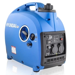
Instruction Manual
PETROL INVERTER GENERATOR
HY1000Si/HY2000Si/HY2000Si-115
WARNING: Read the instructions carefully before use.

CONTENTS
1.0
Safety Information 03
2.0
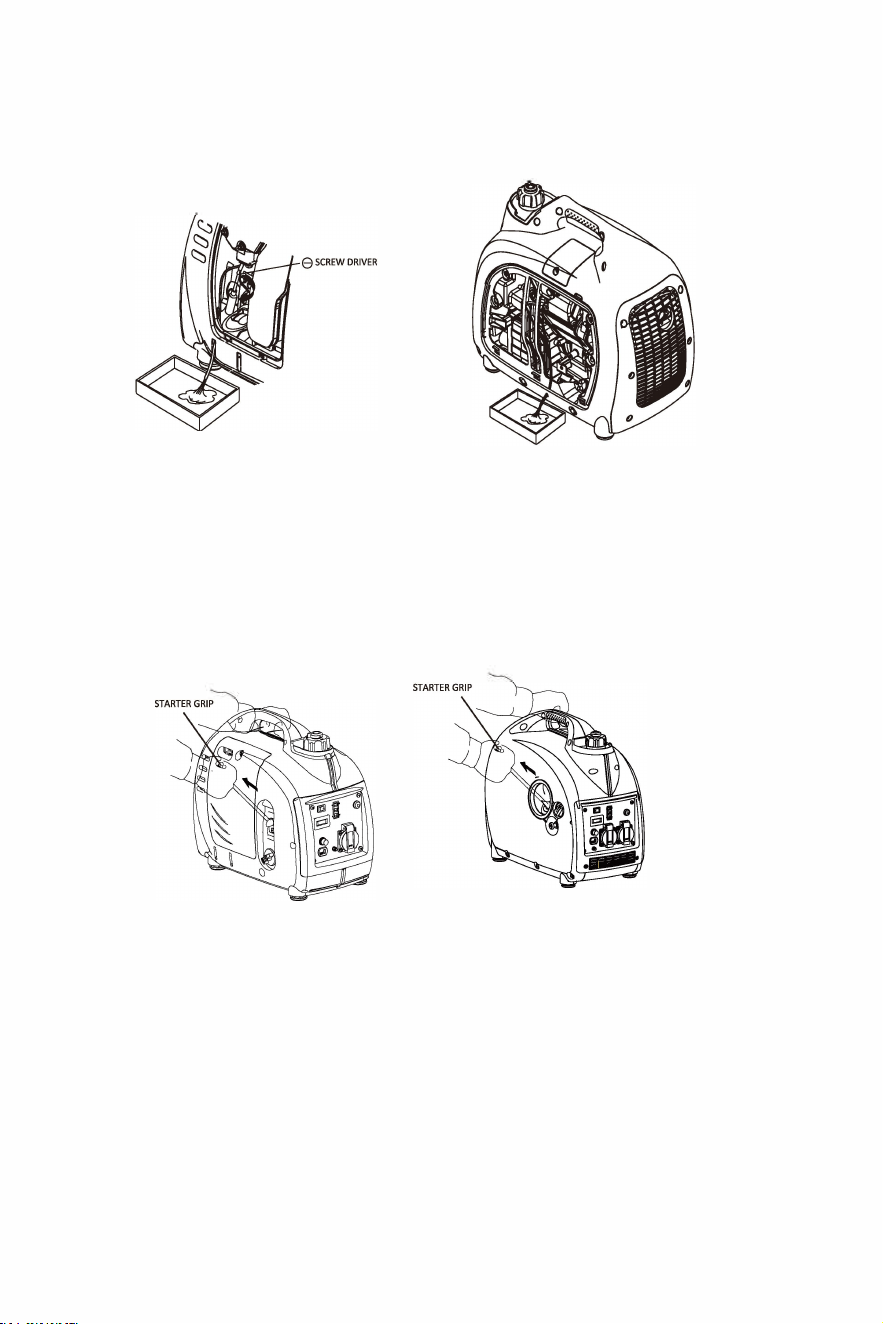
Safety label location
04
3.0
Component Identification
05
1
Control Panel
06
2
ECON Switch
06
3 Hour Meter
07
4.0
Pre-operation Checks
08
1
Oil level Check
08
2
Fuel level Check
09
3 Air Filter Check 10
5.0
Starting the Engine
11
6.0
Generator Use
13
1
DC Applications
14
2
AC Applications
16
3 Output & Overload Indicator
16
4
Oil Alert System
17
7.0
Stopping the Engine
18
8.0
Maintenance
19
1
Oil Change
19
2
Air Cleaner Service 20
3
Spark Plug Service
22
4 Spark Arrester Maintenance
23
9.0 Transporting/Storage
25
10.0
Troubleshooting
27
11.0
Technical Specifications
28
12.0
Wiring Diagrams
29
13.0
Appendix
30
1
EC DEclarations of Conformity
30
2
Environmental Corrections
31
3
Noise & Access
32
14.0
Consumer Information
32
PAGE2
1.0
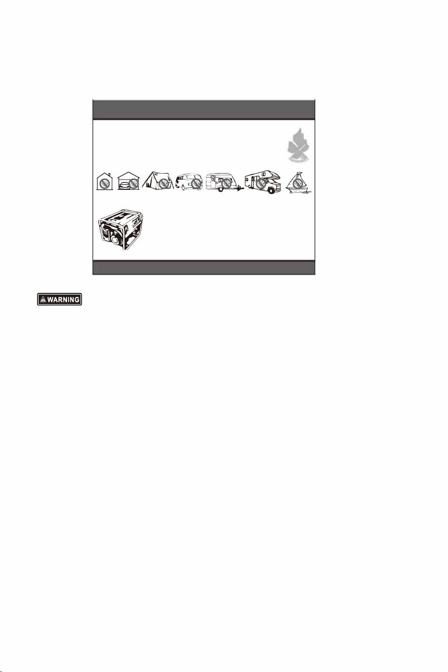
Safety Information.
To protect yourself and your property, please carefully read the following instructions.
A DANGER!
e BREATHING IN CARBON MONOXIDE
'
. FUMES CAN KILL YOU!
•
help ptect against CO poisoning
m install a Carbon Monoxide detector. I
NEVER use Petrol/Diesel powered equipment inside,
especially a home, garage, tent, camper-van,
caravan, motorhome or boat.
EVEN if doors, windows, vents and hatches are open.
Only use OUTDOORS and as far away from doors,
windows, vents and open hatches as possible to
-
prevent inhaling fumes.
READING MANUAL BEFORE USE WILL HELP AVOID OTHER MACHINE HAZARDS.
• Read and understand the user manual before using the generator.
• DO NOT use in an enclosed area or a moving vehicle. The engine exhaust gas contains
poisonous carbon monoxide. Use the generator in a well ventilated area.
• DO NOT touch the hot exhaust. When the generator is running, or before cooling.
• Petrol is explosive and flammable. When refuelling, the generator needs to be stopped,
and fuel kept away from all ignition sources i.e. heaters, lamps, sparks from grinding or welding.
• DO NOT connect to the building's electrical system or another generator, in order to avoid
electric shocks and fires.
• The generator must be kept one metre away from all other equipment and flammable materials.
• Place the generator on a the level surface, in order to avoid overturning or spilling fuel.
• Children and pets should be kept away from the generator at all times especially when in operation.
• DO NOT operate with wet hands.
• DO NOT let the generator to come into contact with rain, moisture or snow.
• All major repair work should be carried out by a professionally trained person.
• DO NOT use the generator for underground work.
• DO NOT use the generator in potentially explosive atmospheres.
• Always use personal protective equipment when you operate or maintain the generator, e.g. gloves,
mask, earplugs.
PAGE3
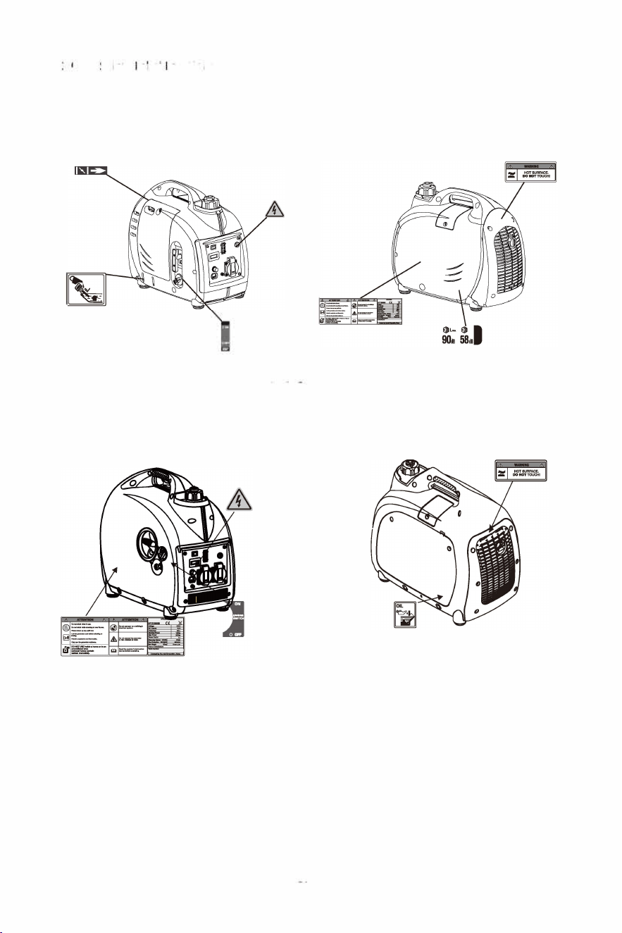
2.0 Safety Label Locations.
H000Si
HY2000Si (HY2000Si-115)
PAGE4
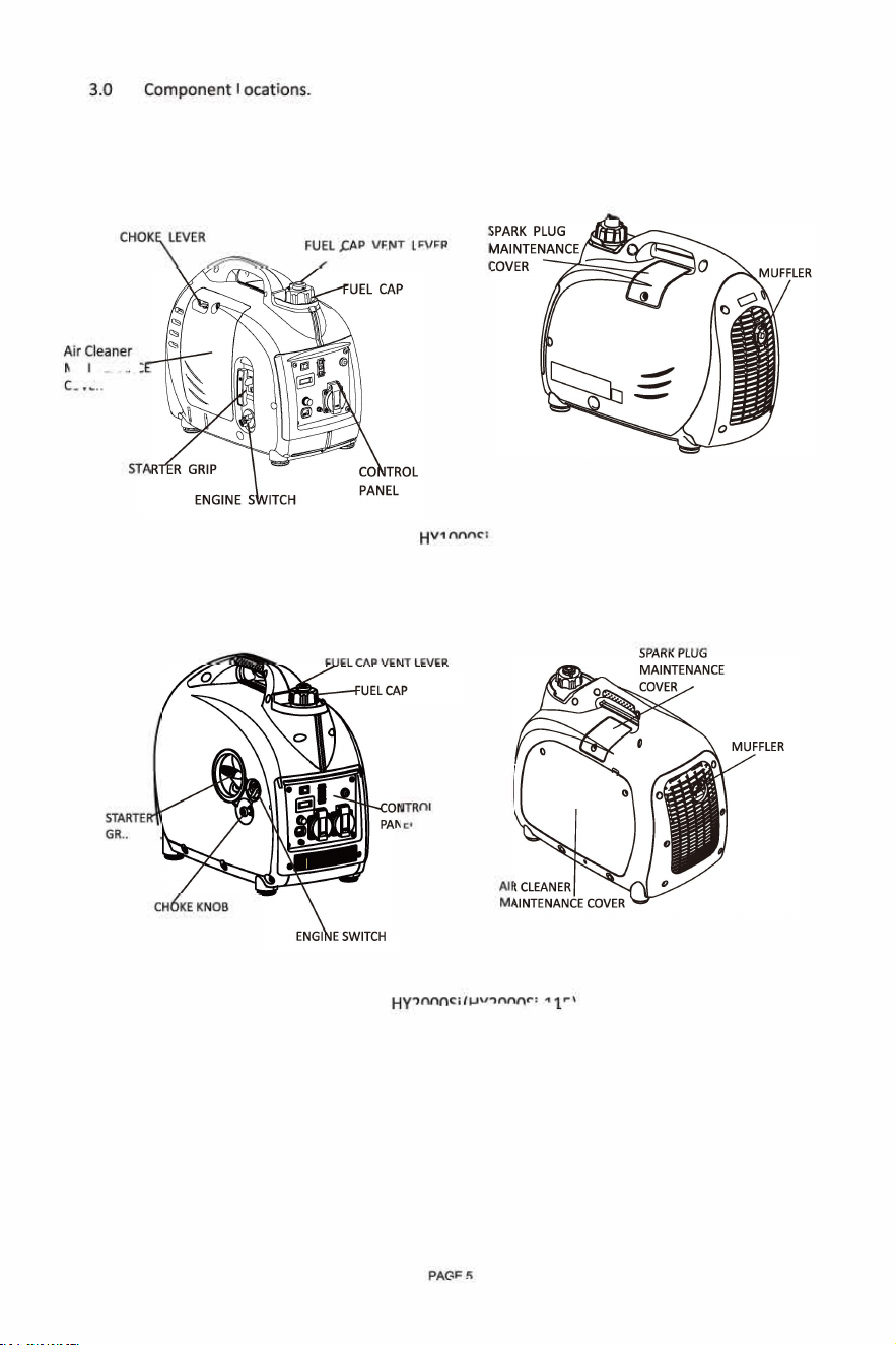
3
.
0 C
o
m
p
onent
L
o
c
at
i
ons
.
C
H
O
K
L
E
VER
F
U
E
L
A
P
V
E
N
T
LEVER
Air Cleaner
MAIN
T
E
N
A
N
C
COVE
R
ST
ART
E
G
RI
P
C
H
K
E
K
N
O
B
HYl0OOS
i
ONTR
O
L
N
E
L
HY2000 Si (HY2000Si
-
1 1
5
)
PAG
E5
3.1
Control Panel.
1 Hour meter
2 AC Output Socket
3 Ground/Earth rminal
4 DC Circuit Protector
5 DC Output Socket
6 Oil Alert Indicator Light
7 Overload Indicator Light
8 Output Indicator Light
9 ECON. SW
HY10Si
HY2000Si
3.2
ECON Switch (Economy Control Switch)
"ON"(
)
HY20Si-115
When the economy control switch is turned to "ON" (--) the engine keeps running
at idle state automatically when the electrical appliance is disconnected, and will
return to the proper speed when the electrical load requires it.
The "ON" (--) function is recommended to minimise fuel consumption, reduce noise and
prolong engine life.
ECO Switch
0
PAGES
OFF
0

NOTE
When a high load electrical appliance is connected and in order to reduce voltage change, turn
the economy control switch to the "OFF"() position. This will allow the engine speed to
increase before the load is applied
In DC operation, turn the economy control switch to the "OFF"()position.
Connect both AC load and DC load, turn the economy control switch to the "OFF"( ) position.
"OFF" ()
When the economy control switch turns to the "OFF" ) the engine runs at high speed.
3.3 Hour Meter
When the generator goes into overload protection mode, the overload indicator light (RED) will
come on, by pressing the "RESET" button the output of the generator can be recovered. It will be
unnecessary to restart engine.
Press and hold the "RESET" button for one second, until the overload indicator light (RED) goes off,
and the output indicator light (GREEN) comes on.
Under non-overload condition the "RESET" button does not have any function.
PAGE?
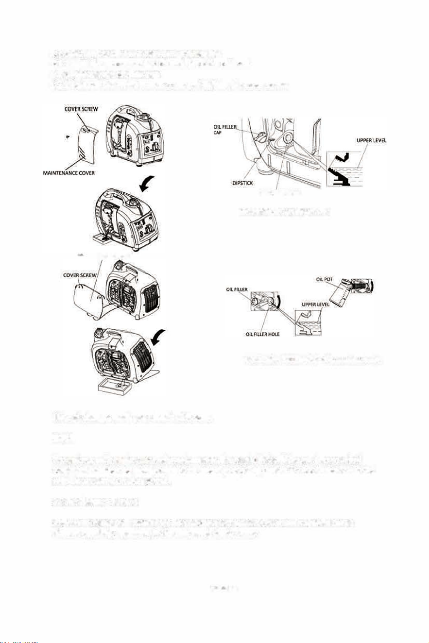
4.0 Pre-Operation Checks.
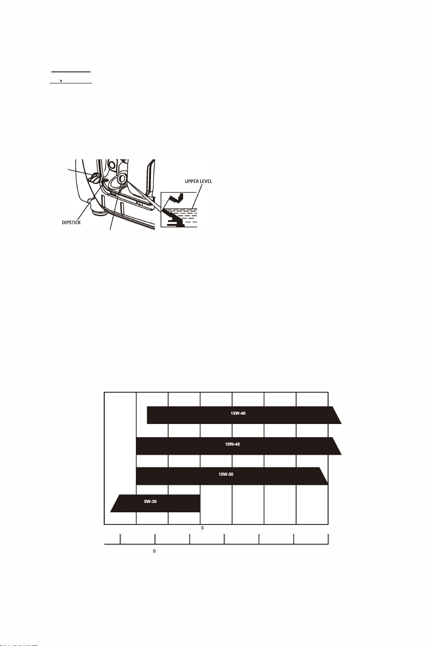
4.1 Oil Level Check.
iM'idNIMdl
Make sure that the generator has been stopped and is on a level surface.
Remove the oil filler cap, and clean it with a clean cloth, reinsert the oil filler cap (do not
screw it in) remove and check the oil level on the dipstick.
If the level is low, fill to the upper limit of the oil filler neck with the recommended oil.
OIL FILLER
CAP
NOTE
OIL FILLER HOLE
HYl000Si-Oil Capacies: 0.25L
OIL�
OILFILLER
EL
�"/
HY2000Si(HV2000Si-115)-Oil Capacies: 0.41L
DO NOT use non-detergent or 2 stroke oil this could shorten the engines working life.
DO NOT mix different types of engine oil in this engine.
Use a 4 stroke engine oil, certified to meet or exceed API standards: SG, SF or SAE
rating.
Make sure that you carefully use and store the engine oil. Avoid getting dirt or dust into the
engine oil.
-30
-20
-10 10
20
30
40
-20 20
40
60 80
100F
PAGES
NOTE
If the engine oil falls below the safety margin the low oil alert system will automatically shut
off the engine. The oil alert indicator light (RED) will come on. To avoid this inconvenience it
is advisable to check the oil regularly
4.2
Fuel Level Check.
Unleaded petrol is the recommended fuel.
Never use stale or contaminated petrol or an oil/petrol mixture.
Avoid getting dirt or water into the fuel tank.
Do not use a mixture petrol containing ethanol or methanol. This will seriously damage
the engine.
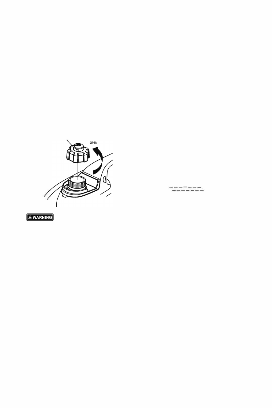
FUEL CAP
Petrol is extremely explosive and flammable.
UPPER LIMIT MARK
_
_
•
I
•
-
�
Fuel ca
p
acities: HYl000Si - 2.2L
,
HY20005i
(
HY2000Si-115
)
3.8L
DO NOT smoke or allow naked flames or sources of ignition in or around the fuelling area or in fuel
storage areas.
DO NOT overfill the fuel tank (DO NOT fuel above the RED upper limit mark). After refuelling make
sure that the fuel cap is closed and secure properly.
Avoid spilling fuel by using correct refuelling methods. ALWAYS clean up spilt fuel immediately
after it occurs.
Avoid breathing in petrol vapours and direct contact with the skin.
KEEP all fuels and oils away from and out of reach from children.
PAGE9
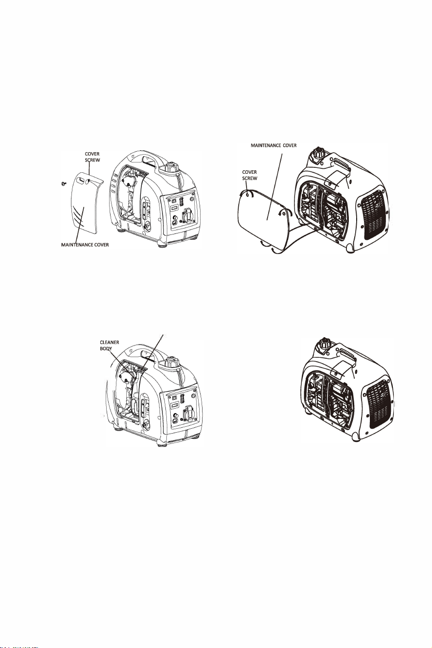
4.3
Air Filter Check.
Check the air cleaner element to make sure that it is clean and in good condition.
a) Undo and remove the maintenance cover scre
w
s, and remove the cover.
b) Press the latch tab on the top of the air cleaner. (HYl000Si
)
Loosen the air cleaner
cover scre
ws.
(HY2000Si/HY2000Si-115
)
c) Remove the air cleaner cover.
d) Check the element, clean and replace as necessary.
AIR
AIR CLEANER
AIRCLEA
�
:
LEMEN
\
€
C
O
VER
I
b
L
O
WE
TAB
HY1000Si
HYl000Si
LATCH
TAB
AIR CLEANER
AIR CLEANER
-·� "�
PAGE 10
HY2000Si (HY2000Si-115)
HY2000Si {HY2000Si-115}
5.0
Starting the Engine.
NOTE
Before starting the engine ALWAYS disconnect the load from the AC Socket.
When fuelling for the first time, or refuelling after long time storage, the engine switch should be
turned on wait for 20 seconds. You will then need to pull the recoil starter 10 to 20 times to
draw fuel into the carburettor.
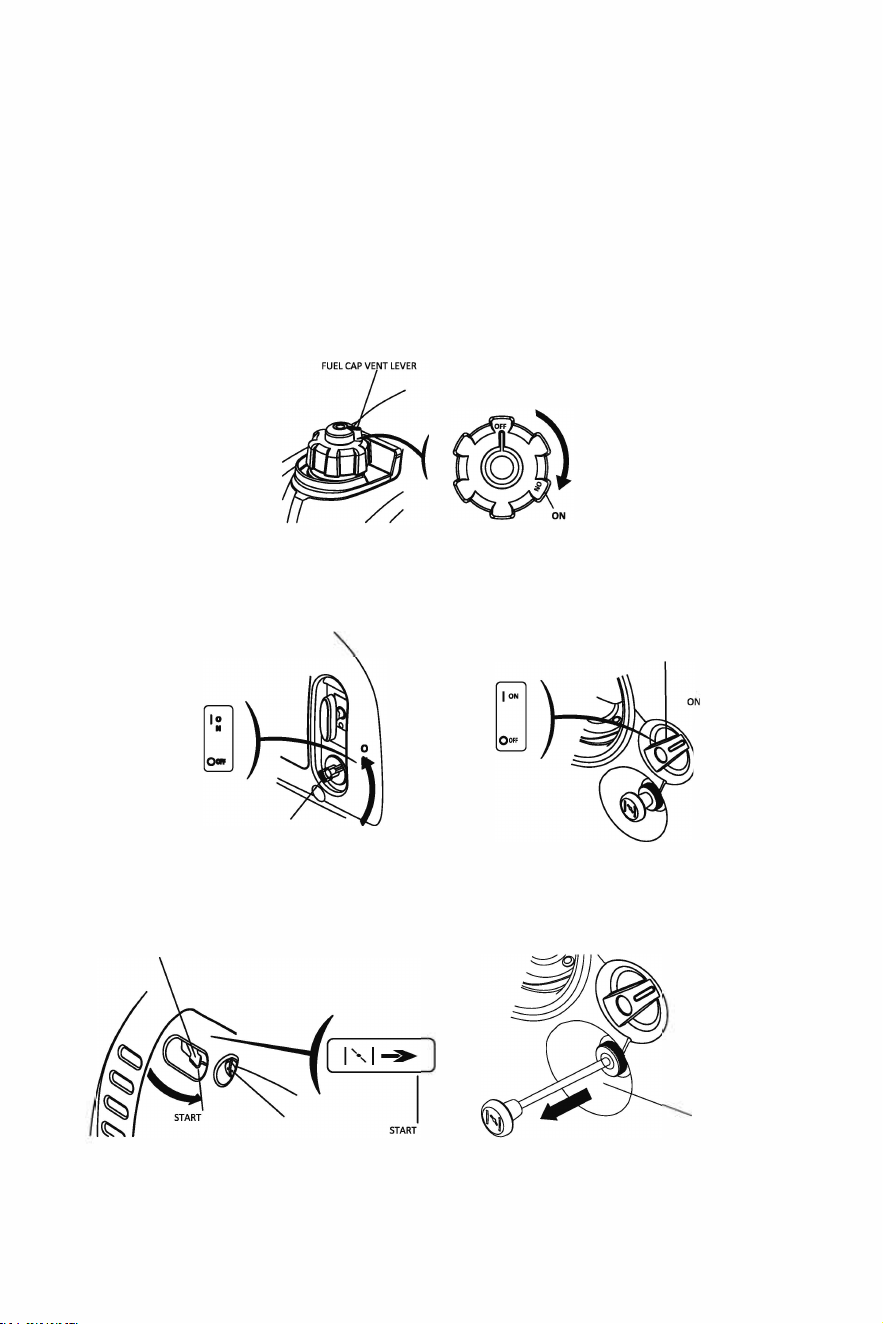
5.1 Turn the fuel cap vent to the "ON" position. When transporting the generator, turn the
fuel cap vent lever to the "OFF" position.
5.2 Turn the engine switch to the "ON" position.
ENGINE SWITCH
)
HY1000Si
HY2000Si ( HY2000Si-115)
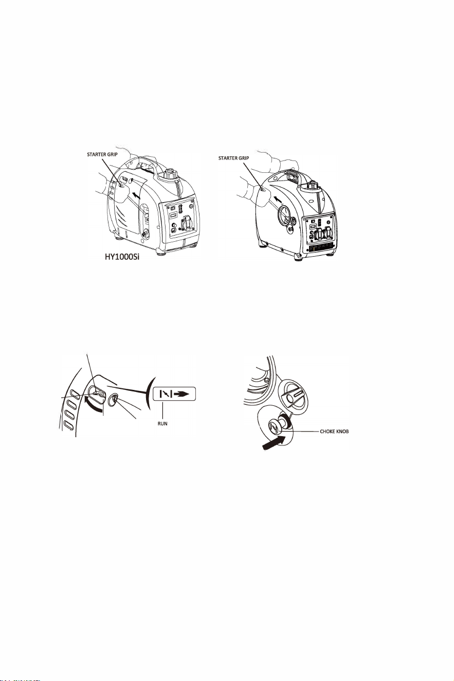
5.3 HY1000Si - Move the choke lever to the "START" position.
HY2000Si (HY2000Si-115) - Pull the choke knob fully out.
CHOKE LEVER
CHOKE KNOB
HY1000Si
HY2000Si (HY2000Si-115)
PAGE 11
NOTE
DO NOT move the choke lever (HYl000Si) to the "START" position when the engine is hot
or ambient temperature is high.
DO NOT pull the choke knob (HY2000Si/HY2000Si-115} to the fully out position when the
engine is hot or ambient temperature is high.
5.4 Pull the starter grip lightly until you feel resistance, then pull quickly toward the arrow as
shown below.
NOTE
HY2000Si
HY2000Si-115
Return the starter grip slowly by hand. DO NOT let the starter grip spring back.
5.5 After starting and warming up the engine, turn the choke lever (HYl000Si) to the "RUN" position.
After starting and warming up the engine, push the choke knob (HY2000Si/HY2000Si-115)
to the normal position.
RUN
NOTE
CHOKE LEVER
HYl000Si
HY2000Si
HY2000Si-115
If the generator stops and cannot be restarted check the oil level first.
Carburettor Modification for High Altitude Operation.
At high altitude, the standard carburetor air-fuel mixture will be too rich. Performance will
decrease, and fuel consumption will increase. A very rich mixture will also foul the spark plug
and cause difficult starting. If the generator operates at high altitude, change the main-nozzle
or adjust the idling screw of carburetor.
PAGE12
If the generator always operates at altitude above 1,000 meters, contact your dealer to modify
the carburetor.
Generator output power should be modified according to the altitude and ambient
temperature. The correction factor refers to 13.
If the carburetor has been modified for high altitude operation, the air-fuel mixture will be too
lean for low altitude use. Operation at low altitude may cause the engine to overheat and
result in serious engine damage. The carburetor needs to be returned to its original
specification.
6.0
Generator Use.
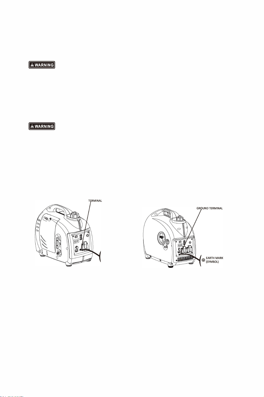
Make sure to ground/earth the generator when the connected appliance is grounded/earthed.
DO NOT connect to the buildings electrical system. Back feeding it is both illegal and highly
dangerous.
GROUND
HYlO00Si
@
EARTH MARK
(SYMBOL)
PAGE13
HY2000Si
HY2000Si-115
IUYM;JWl
For continuous operation, do not exceed the rated output power of the generator.
DO NOT make parallel connection with mains electrical installations or other generators.
DO NOT connect an extension to the exhaust pipe.
When an extension cable is required, make sure that you use a tough rubber sheathed
flexible cable (according to IEC245 or equivalent standards). The length of the extension
cable:
60m for cable of 1.5 mm
'
100m for cable of 2.5 mm
'
Keep away from other electric cables or wires.
NOTE
The AC socket outlet can be used while the DC power is in use. If using both at same time, be
sure not to exceed the total power for AC and DC.
(HYl000Si AC - 0.9kVA, DC - SA)
(HY2000Si/HY2000Si-115 AC - 1.6kVA, DC - SA).
Most motor appliances require upto 3 times more than their rated wattage when starting.
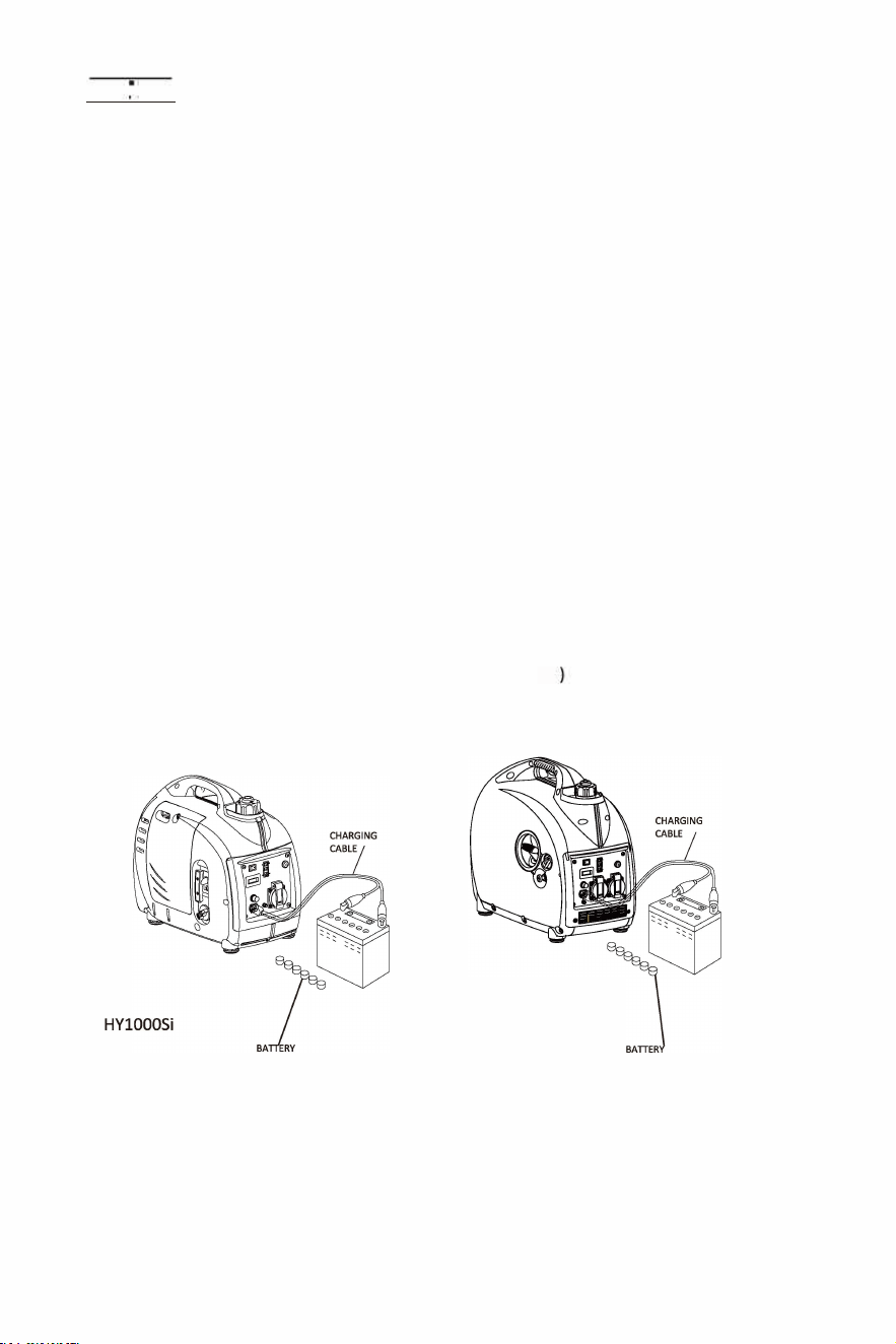
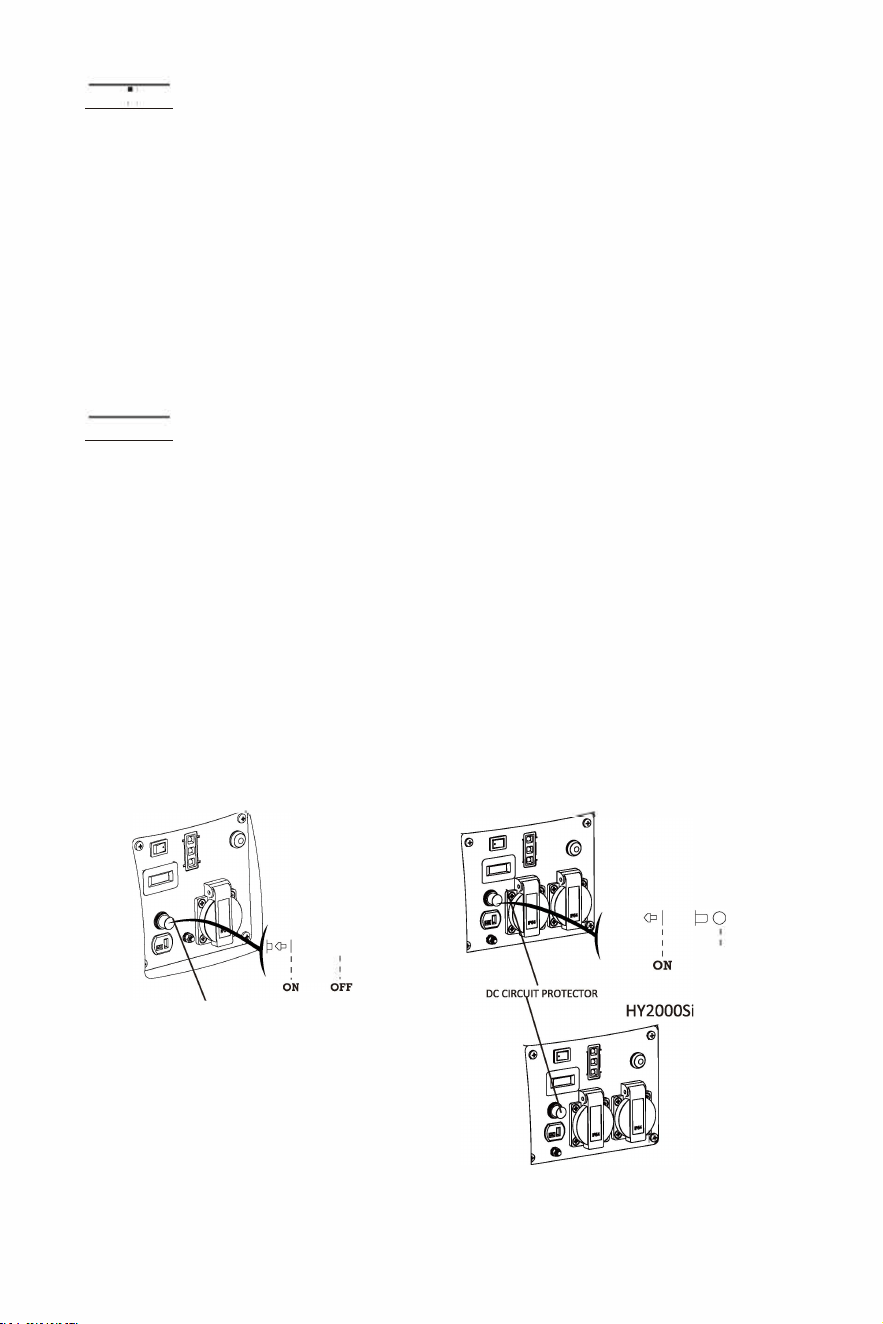
6.1 DC Application.
The DC receptacle, 15-30V under no-load condition, may be used for charging a 12V battery only.
NOTE
In DC operation, turn the ECON Switch to the "OFF" position (
6.1.1 Connect the DC receptacle to the battery terminals with the charging cable.
HY2000Si
( HY2000Si-115)
VENT CAPS
VENT CAPS
PAGE14
IHM;Jhldl
To avoid producing the sparks at the terminals of battery, connect the charging cables firstly
to the battery terminals, and then to the generator. When disconnecting the cables do so first
at the generator.
Before connecting the charging cables to a battery that is installed in a vehicle, the grounded
/
chassis cable of the battery should be disconnected first. This sequence will prevent sparks or
a short-circuit, if the cable accidentally contacts the vehicle's frame or body.
NOTE
Do not start the car's engine when the generator is still connected to the battery, otherwise the
generator will be damaged.
Connect the positive battery terminal to the positive charging cable. Do not reverse the charging
cable, otherwise generator or battery will be damaged seriously.
lbMdhldl
When charging the battery releases highly explosive oxygen
/
hydrogen gases. Keep the battery
away
from sparks/
fire and other sources of ignition. Always charge the battery in a well
ventilated area.
Battery electrolyte contains sulphuric acid which will cause severe burns if it comes into
contact with the skin and eyes. Therefore it is necessary to wear the protective clothing and
mask.
If battery electrolyte gets into eyes or onto skin, flush thoroughly with warm water for 15
minutes at least, and call a doctor immediately.
If you accidently swallow any battery electrolyte, call for medical
/
first aid assistance
immediately. If no medical/first aid assistance is available call or get someone else to dial 999.
Keep batteries and electrolyte OUT OF REACH OF CHILDREN.
NOTE
The DC receptacle can be used while the AC power is in use.
When DC circuit overload will trip the DC circuit protector, remove load firstly, and then reset the
protector after a few minutes.
PO
'
OFF
DC CIRCUIT PROTECTOR
HYlO00Si
HY2000Si-115
PAGE15
6.2 AC Applications.
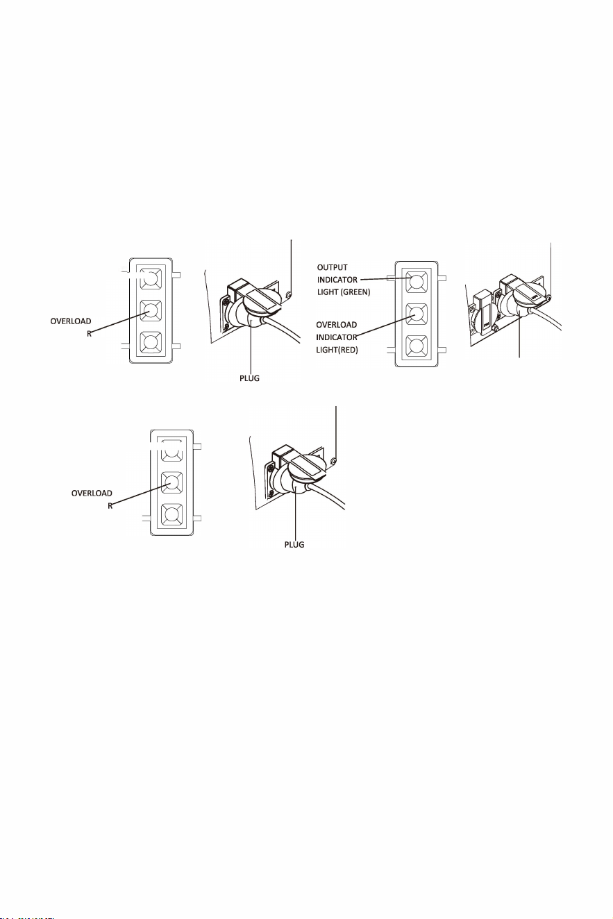
6.2.1 Start engine and make sure the output indicator light (GREEN) is on.
6.2.2 Confirm all electrical appliances are switched o, then connect the appliance plugs to
the generator AC socket.
NOTE
To obtain the best working and longest working life of the generator, you should make
sure that you run the generator for 20 hours at 50% rated load.
OUTPUT
INDICATOR -
LIGHT (GREEN)
INDICATO
LIGHT(RED)
OUTPUT
HY1000Si
INDICATOR -I
LIGHT (GREEN)
INDICATO
LIGHT(RED)
NOTE
HY2000Si-115
HY2000Si
PLUG
Confirm all electrical appliances are in good working condition before connecting them to the
generator. If an electrical appliance becomes abnormal, sluggish, or stops suddenly, shut off the
generator engine immediately, and disconnect the appliance.
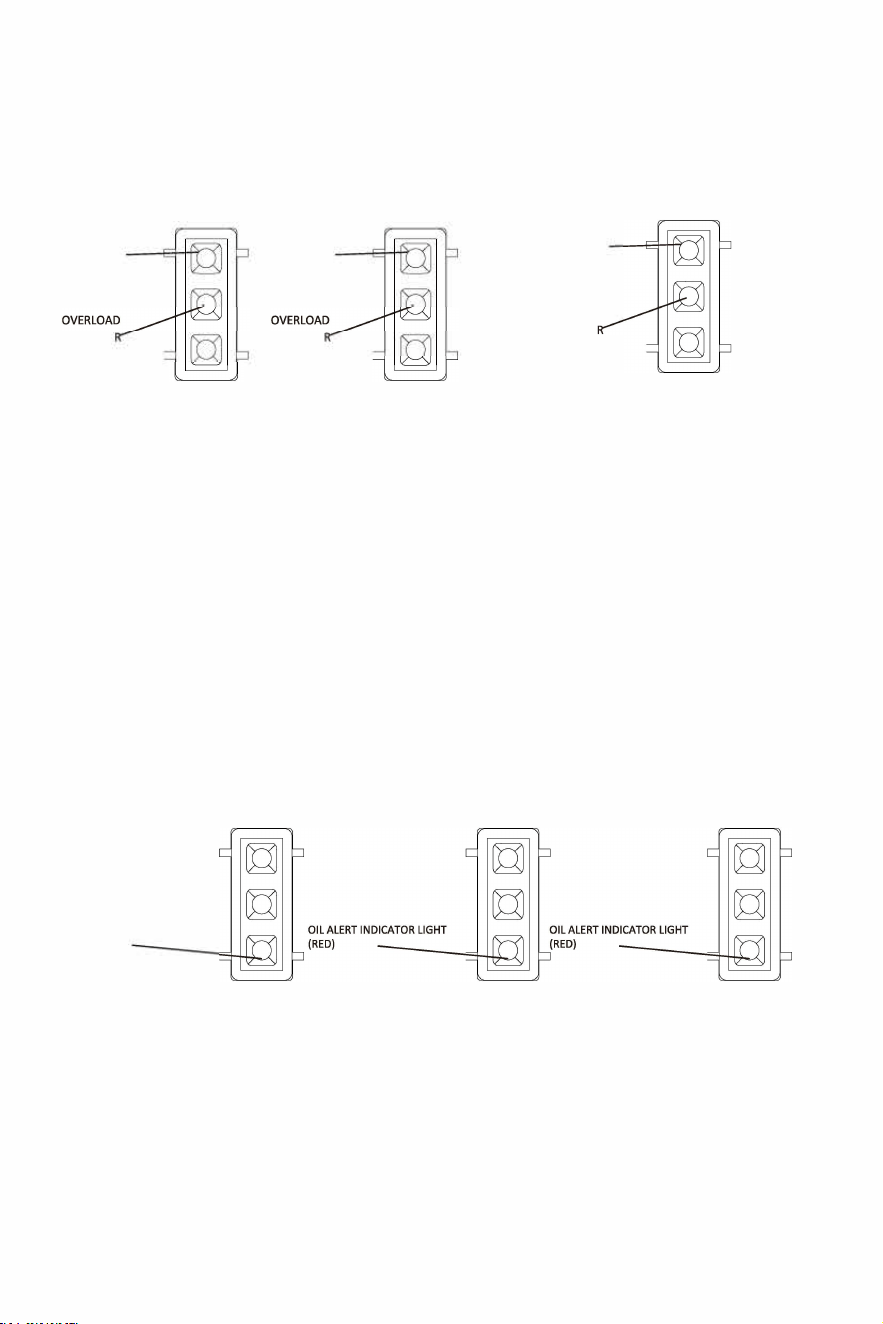
6.3 Output and Overload Indicator
In normal operating conditions, the output indicator light (GREEN) will remain on.
If the generator is overloaded (HV1000Si - overQ
.
9
k
, HV2000Si/HV2000Si-11S-
over1
.6k
V
A),
or the connected appliance is short-circuited, the output indicator light (GREEN) will go out, and
overload indicator light (RED) will come on. The AC output will be cut and the engine will remain
running.
PAGE16
If the overload indicator light (RED) is on, disconnect the electrical appliances first, then press
and hold the reset button for 1 second. If the overload indicator light (RED) is off and the
output indicator light (GREEN) is on, reconnect the electrical appliances. Otherwise stop the
engine and check the generator.
OUTPUT
OUTPUT
OUTPUT
INDICATOR
INDICATOR INDICATOR
LIGHT (GREEN) LIGHT (GREEN)
LIGHT (GREEN)
OVERLOAD
INDICATO
INDICATO
INDICATO
LIGHT(RED)
LIGHT(RED)
LIGHT(RED)
HYl000Si
HY2000Si
HY2000Si-115
NOTE
When you start the engine, it is normal for both the overload indicator light (RED) and output
indicator light (GREEN) to be ON simultaneously. The overload indicator light will go OFF after S
seconds, otherwise contact your dealer.
6.4 Oil Alert System.
The oil alert system is designed to prevent engine damage caused by an insufficient amount of oil
in the crankcase. Before the oil level in the crankcase falls below a safe limit, the oil alert system
will automatically shut down the engine (the engine switch remains in the "ON" position).
If the oil alert system shuts down the engine, the oil alert indicator light (red) will be on. Check
the engine oil level.
OIL ALERT INDICATOR LIGHT
(RED)
HYl000Si
HY2000Si
HY2000Si-115
PAGE17
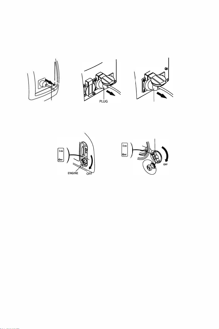
7.0 Stopping the Engine.
To stop the engine in an emergency, turn the engine switch to the "OFF" position.
7.1 Switch off the connected electrical appliances and remove their plugs from the AC sockets.
PLUG
HY1000Si
HY2000Si
7.2 Turn the engine switch to the "OFF" position.
SWITCH
HY1000Si
7.3 Turn the fuel cap vent lever to "OFF" posion.
NOTE
PLUG
HY2000Si-115
ENGINE
HY2000Si (HY2000Si-115)
Make sure the fuel cap vent lever and engine switch are in the "OFF" position, aer stopping
and when transporting and storing the generator.
PAGE18
8.0
Maintenance.
The purpose of the maintenance schedule is to keep the generator in the best operating
condition.
Stop the engine before performing any maintenance. If the engine must run, be sure the area is
well ventilated. The exhaust contains poisonous carbon monoxide gas.
Only use genuine Hyundai spares to replace worn components.
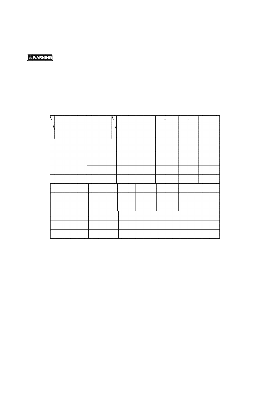
Maintenance Schedule.
\
Regular Service
\
First
Every 3 Every 6
Every
Period (3)
Each
month
months months
2
yers
u,e
or
or or or
10 hri.
Item
50 hrs. 100 hrs. 300 hrs.
Engine
Check level
oil
Change
Air
Check
cleanr
Clean
0(1)
Spark plug Check-adjust
Spark plug
Replace
Spark arrester
Valve clearance
Check-adjust
(2
)
Combustion
Clean
After every 300 hrs(2)
chamber
Fuel tank& filter
Clean
Every year(2)
Fuel line
Check
Every 2 years (Replace if necessary)(2)
NOTE
(1) Service more frequently when used in dusty areas.
(2) These items should be serviced by your servicing dealer, unless you have the proper tools and
are mechanically proficient. Refer to dealer for service procedures.
(3) For commercial use and/or long hours of operation you must maintain proper maintenance
intervals.
8.1 Oil Change.
Drain the oil whilst the engine is still warm.
8.1.1 loosen the maintenance cover screw, and remove the cover.
8.1.2 Remove the oil filler cap.
PAGE 19
8.1.3 Drain dirty oil Into a container thoroughly.
8.1.4 Refill the recommended oil and che�k the oil level.
8.1.5 Reinstall the 9il filler cap.
8.1.6 Reinstall the- mafntennce cover and tlgt,ten the cover screw.
OtL Fill£� HOLE
HY1000S1·011 Capad�: 0.2Sl
MAN VU
HY2000Sl(HY2000Sl-ll5)-0ll Capa: 0.4ll
After oil change, wash your hands with seap.
NO
To conform with environ mental requirements, the used oil should be put Into a sealed
container and then b
.
e transported to an amenity recycling centre. Do not throw It Into the
rubbish or pour it on the ground.
8.2 Air Cleaner• Service.
A irty air cleaner will restrict air flow into the carbretor. Clean and malntaln the air
cleaner regularly; especially in the extremely dusty areas.
PAGE
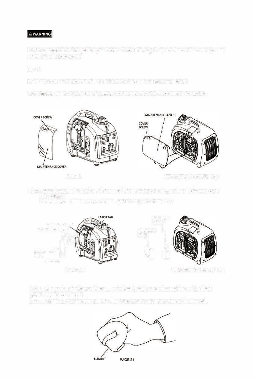
Do not use, petrol or low ignition paint solvents for cleaning. They are flammable and explosive
under certain qndltions.
NOTE
Never run the generator without qlr cleaner,or rapid engine wear may occur.
8.2.1 Lo.osen the screw
.
s of the air cle
.
aner maintenance cover, and remqve the cover.
HYlOOOSI
HY2000S1 (HV2000Si-115)
8.2.2 Press down the latch tab on the top of the air cleaner, and open the air clean·er cover.
(
HY1000Si)
Loosen the air cleaner cover screws. (HY2000S1/HY2000Si·ll5)
AIR CLEANER
.ArR Cl.EANER ElEMENT
��
�l�ClER .
lERTAB
HYlOOOSI
AIR EANt�
lMENT
AIREANER 6
1
HY2000Sl(HY2000S1-11S)
8.2.3 Take out the air cleaner element, and clean It with a non-flammable or high fla
·
sh
pont solvent, then dry it.
8.2.4 Soak the air cleaner element air filter In oil, and squeeze out the redundant oil.
8.2.5 Refit the air cleaner element and cover.
8.2.6 Refit the maintenance cover, and tighten the screws.
8.3 Spark Plug Service.
Recommended spark plug: A5RTC
(
HY1000Si
) /
E6RC
(
HY2000Si
/
HY2000Si-115
)
Check the spark plug gap and clean the carbon deposition at the bottom of the spark plug.
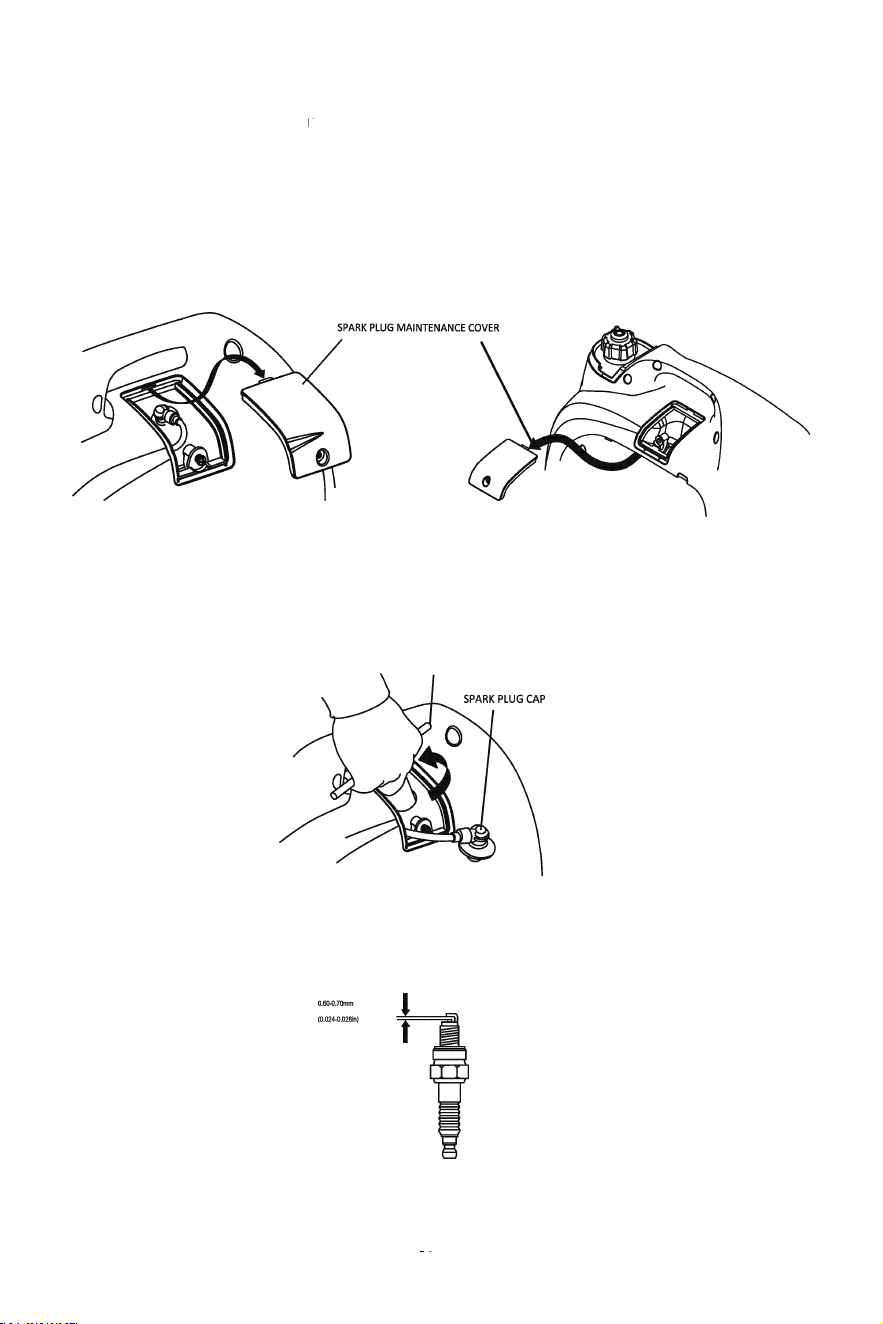
8.3.1 Remove the spark plug maintenance cover.
HYlO00Si
8.3.2 Take off the spark plug cap.
8.3.3 Clean the carbon deposition at the bottom of the spark plug.
HANDLE BAR
8.3.4 Take off the spark plug with the spark plug spanner.
a
HY2000Si (HY2000Si-115}
8.3.5 Visually inspect the spark plug. Change for a new one if its insulator is cracked or
chipped. Clean it with a wire brush if the spark plug is going to be re-used.
PAGE 22
8.3.6 Measure the spark plug gap with a feeler gauge. The normal value: 0.6-0.7mm (0.024-
0.028in). Adjust the gap by bending the electrode carefully.
8.3.7 Refit the spark plug carefully, by hand, to avoid cross-threading. A new spark plug
should be tightened 1/2 turn with a spanner. A used spark plug should be tightened 1/8 to
1/4 turn with spanner.
8.3.8 Reinstall the spark plug cap.
8.3.9 Reinstall the spark plug maintenance cover.
NOTE
The spark plug must be securely tightened. If refitted incorrectly (i.e. cross threaded) this will damage
the cylinder head.
Never use a spark plug with an improper heat range.
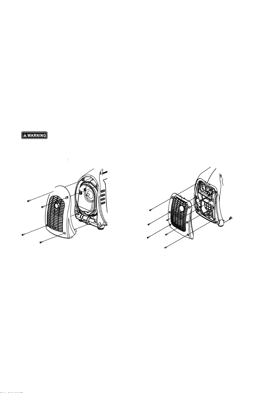
8.4 Spark Arrester Maintenance.
The spark arrester must be maintained every 100 hour service.
8.4.1 Remove the four/six screws, and remove the exhaust guard.
HYl000Si
PAGE 23
HY2000Si (HY2000Si-11S)
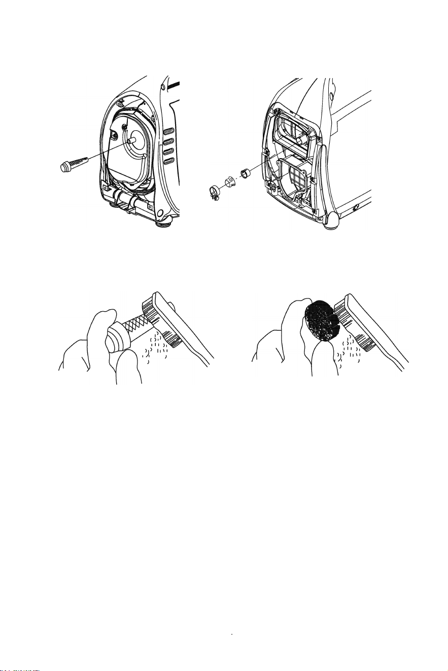
8.4.2 Once the engine cools down remove the spark arrester from the exhaust.
HYl000Si
HY2000Si (HY2000Si-115)
8.4.3 Remove carbon deposits of the spark arrester using a wire brush. If the spark
arrester is worn, replace it.
HY1000Si
HY2000Si(HY2000Si-11S)
8.4.4 Refit the spark arrester and exhaust guard.
PAGE24
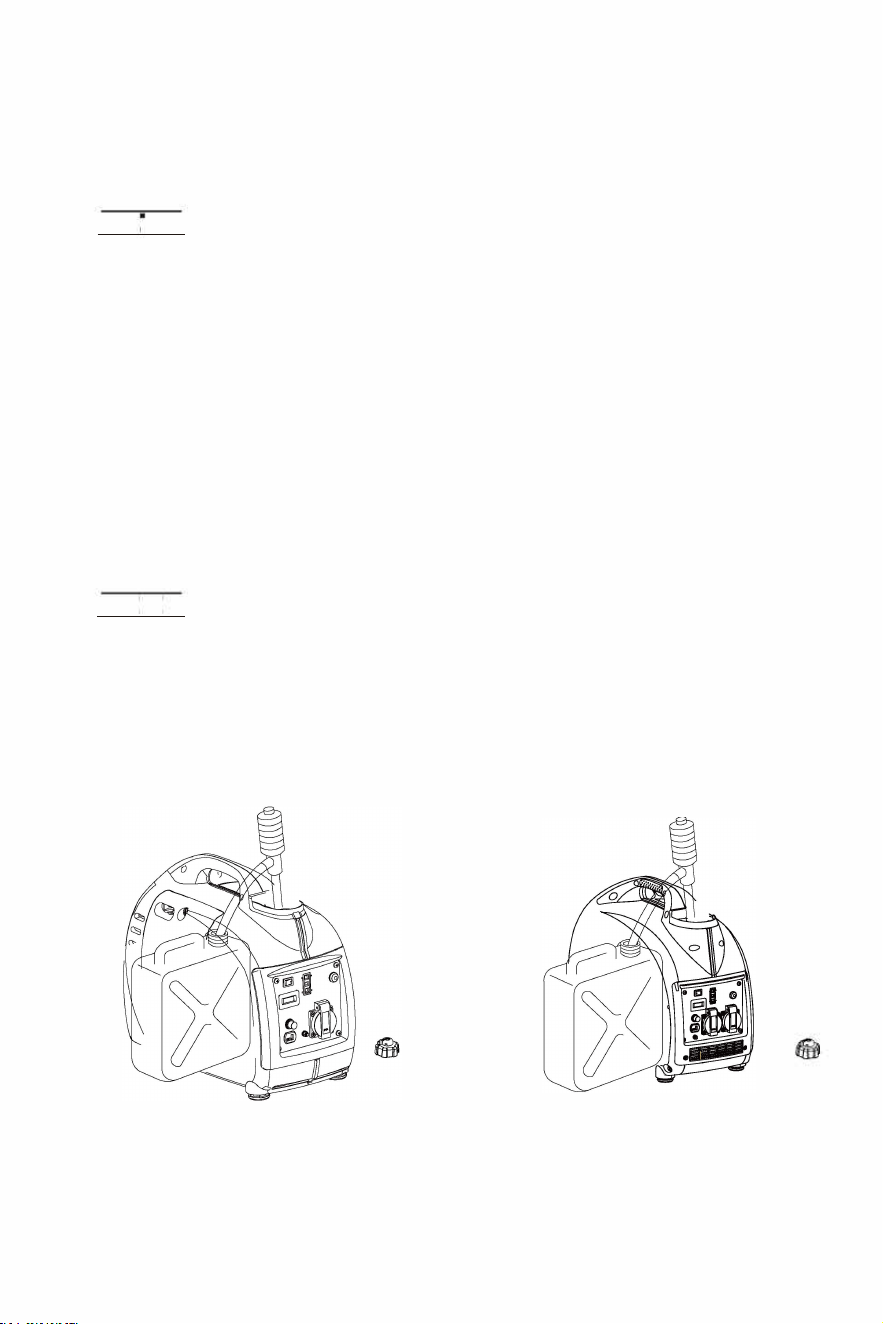
9.0 Transporting/Storage.
Avoid fuel spillages during transportation or temporary storage, both the engine switch and
the fuel cap vent lever should be turned to "OFF" position, and the generator should be turned
off. DO NOT move a running generator, turn it off then move to new location.
IH\i;JWdl
Transporting the Generator.
DO NOT overfill the fuel tank.
DO NOT use the generator inside the transport vehicle. The generator should be used in an
open and well ventilated area.
Avoid exposure to direct sunlight when the generator is being transported in an enclosed
transport vehicle. High temperatures inside the transport vehicle could cause fuel to vaporise
resulting in a possible explosion.
Drain off the fuel, when the generator is transported on rough roads.
Storing for a long period:
9.1 Make sure the storage area is clean and dry.
9.2 Drain off the fuel.
lYOdWHdl
Petrol is highly explosive and flammable, keep away from naked flames and all other
sources of ignition.
a. Drain off the petrol in the fuel tank, and store in a suitable container.
HYl000Si
HY2000Si{HY2000Si-115)
PAGE25
b. Turn the engine switch to "ON" position, and loosen the carburetor float bowl drain screw to discharge
from inside of carburetor float bowl.
HYlO00Si
HY2000Si (HY2000Si-115)
c. Take off the spark plug cap, pull the recoil starter grip three or four times, discharge the petrol from
the fuel pump and fuel lines.
d. Turn the engine switch to "OFF" position, and tighten the drain screw of carburetor.
e. Reinstall the spark plug cap.
HYlO00Si
HY2000Si (HY2000Si-115)
9.3 Change the engine oil.
9.4 Remove the spark plug, and pour a tablespoon of clean engine oil (10~2oml) into the
cylinder. Revolve the engine several times to distribute the oil, and reinstall the spark plug.
9.5 Pull the starter grip slowly until you feel resistance. At this point, the piston is coming up on
its compression stroke and both the intake and exhaust valves are closed. In this position, it
helps to protect the engine from internal corrosion.
PAGE 26
10.0 Troubleshooting.
HYl000Si - Troubleshooting
Appliance doe• not operate
en the engine cannot be staed:
I• th• output indicator
light ON?
KO
I• there fuel in th• tank? Rofill tho fuol tank
YES
I■ th• •ngin• ■witch ON?
S
I■ tho fuol cap Tont lonr ON?
S
Is the choke lever STT ?
S
i. there •nough oil in the
engine?
S
i. the ■park plug in good
condition?
YES
If th■ ■ng■ ltU doH not ■ta,
contd on antbori-1 HTUDAl
dea•r
NO
RO
NO
Turn th• engine ■witch on
m the fl n1 r on
Tum ihe choke lever to
ST
Clean, readju■t gap and
dry th• ■pr plug
replace it lf nH■ary
HY2000Si (HY2000Si-115)
- Troubleshooting
en the engine cannot be started:
Is there fuel in the tank?
YES
I■ the •ngin• ■witch OH?
YES
I■ the fu•l cap nnt lenr ON?
I■ the choe knob pull out?
YES
I• thoro onouh oil in tho
onino?
YES
I■ the ■park plu in good
condition?
B
If the engin• ■tl doe■ not
•ta, contact an thori1ed
HND dealer
NO
XO
Refill the fuel tank
Turn 1he engine switch on
m &.l cop nl ir on
Pull th• chob knob fully
out
Add the recommended oil
Clean, readju■t gap and
dry the ■park plug
replac• it if nece■■ary
Contact an
authorised HYUND
de1-r
--K-0--
�:t��:= ND
�------�
doolor
YES
�------�
Stop engine nd then replace orrepirthe appliance
DC receptacle without any electricity
��:/f ectrical
appliance
YES
Ce or rece t
RO
I■ the DC circuit
protoctor ON?
YES
Pu■h the DC circuit
-- protoctor ON.
Appliance does not operate
I■ the output indicator
light ON?
NO
Coact an uthorited
UND d•al•r
DC receptacle without any electricity
Check
the electrical o
pplianc•
C
h
a
n
ge or le the ice
for any frru
YES
NO
Is the DC circuit
protector OFF?
RO
Contact an authoriad
HYUNDAI dealer
PAGE27

11.0 Technical Specifications
HYl000Si Technical Specifications
Specification■
Parameters
DC Output
Mod•l
HSIZ0Oi.l
Fuel Tank Volume
P
•
4-atro•, OYUhead val•,
1ingl• qlind•r, forced-air cooling
ConRngm
53.2cm'
"
n
Bore•Strok•
43.5n
35,8mm
WorgT1p1r1
Compression Ratio
1,6.5
Rated Spe.d
5500min
1
Ignition 8•t•m Fl transistor
M.titudo
• Noi1& (dBm) L
• • oiH (dB/7m) L.�
Start Syatem
R.:oiltarter
Dmtn1i1IL*B)
el pe
Unlded ptrol
N•Weht
Oil Capacity
0.251
Oil Model
SE 15W-30
Model
HYI000Si
a
-�
SOH•
Rated Voltage
230V
Rated Current
3.9A
o
5
3
QQ
"l
od Spood
omin,: Pow,r
0.9kW
Maximum Power
LOkW
HY2000Si (HY2000Si-115)Technical Specifications
Specifications
Parameters
DC Output
Modal
B80-i
0
Fuel nk Volume
Type
4-■1roke, oyerhead yab·•,
ling!• cyllnder, Jorc•d-oircoolig
me
79cm,
Bora•Stroka
48.8mm
1
3.0mm
z
Compression Ratio
L 6,7
0
Rr 2.3k�500n'
Ignition Sy■l•m
ll tran■i ■tor
Start Syt•m
Recoil stoer
,-
m
q-t:,_
Max.Altitud•
* Noise L
• • Noi1•L
0
iL"B)
z
Fuel Type
UnlHd•d p•trol
Net W•ihl
Oil Capacity
0.411
Oil Model
SE 1530
Model
2000Si
HT2000Si-l 16
0
Rated frequency
50Hz
50Hz
z
Rated Voltage
230V
115V
Rated Current
7.0A
13.BA
0
RatodS
45□om
500min
NominI Power
L6W
l.BW
Maximum Power
.0W
2.0kW
Noise level is measured when the ECON Switch is turned to "ON"
• :L.A shows the guaranteed sound power tested by 2000/14/EC.
12Vi5A
2.21
6.6h
�S00g/(kW.h)
-20
°
C ~ 40'C
1000
80
5<~58
451mm • 242mm • 379mm
m
12V/5A
3.BL
8.0h
<500g/(kW.h)
-2Dt~40t
1000m
90dB4m
54~59dBt7m
510mm•,ssmm•2somm
20kg
' •: The noise level in "dB/7m" is the arithmetic mean value of sound press level(Le,) in
four directions measured 7 meters away from the generator.
The noise level may vary in dierent environments.
PAGE28
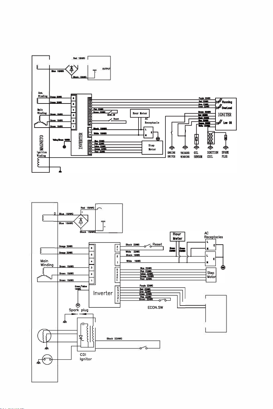
12. 0 Wiring Diagrams
HY1000Si
�
j•-· ·�µ-•-�1-T }
HY2000Si
DC
Windin
Aux.
Winding
CDI Winding
Oil
Sensor
1
+
O
�-� -_ -_ -_ -_ -_ -_
�Runnig
WOverload
INDITOR
�:::
0
1
�
:::::::::::::::::::::::::::::::� Low O
i
l
R 2
ENGINE. SW
PAGE 29
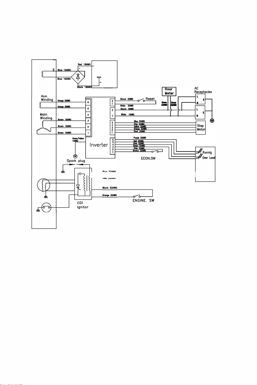
HY2000Si-115
DC
Windin
CDI Winding
Oil
Sensor
13.0 Appendix.
�l +
INDIR
����============
Low Oil
13.1 EC Declaration of Conformity
PAGE30

(€
ECDECLA RATIONOFCONFORMITY
Forthcllowingmachincr y:
odct 1e:RRGERAR
Model: HY1000SY2000S00i-115
(€
is hcrcwilh confirmed to lll all th e relevant provisions of Machinery Directin
(206/42/EC)andcomplywithLow-VoUageDirective(2006/95/EC & 2014/35/EU),
Electr omagnetlcCompat ibility Directive (2004/108/EC & 2014/30/EU)
and Noiu Emission Directive 96UC, 1u1ce1tdedby2005/88/E
aadtltefollowin&harmonized standard have bcc ncomplicd with:
12601:201D;
EN 61000-6-1:05;
EN 61000-6-4:1007
Resp onsl leformaklng this de daraon Is I he:
Manufacturer Authorized representave estalishedwlthlnthe EU D
GENPOWER LTD
Manufac turer's Na me
Manufacturer'sAddre
Isaac Way, Pembroke Dock, Pembrokeshire,
UK, SA724RW
Authorised Re p's name:
Authorized Re p's Address:
Person responsible for the te chnical files established within the EU.
first name&surname:
Kevin Stanley
Address:
GENPOWER LTD Isaac Way, Pembroke Dock,
Pembrokeshire, UK, SA72 4RW
Person responsible for making this declaraon
Name,Surname:
Kevin Stanley
Posion/Tit le: Product Manager
13.2 Environmental Corrections.
The standard condition of rated power output;
Altitude;
O metres
Ambient Temperature
2
5 'C
Relative humidity;
1%
Ambi•nl ternpuature
Altitude(m)
25
30
35
0.9!
0.96
500 0.93 0.91 0.89
1000
0.87 0.85 0.82
2000
0.75
0.73
0.71
3000
0.64
0.62
0.60
4000
0.54 0.52 0.50
PAGE31
40
0.93
0,87
0.80
0.69
0.58
0.48
45
0,90
0,84
0.78
0.66
0.56
0.46

NOTE
Relative humidity 60% correction factor
Relative humidity 80% correction factor
Relative humidity 90% correcon factor
Relative humidity 100% correction factor
Example :
C- 0.01 ;
C-0.02;
C- 0.03 ;
C- 0.04 ;
Rated power (P) 1.6kVA generator (Altitude: 1000m) Ambient temperature: 35
°
C,
relative humidity: 80%
P=Pn *(C-0.02) = l.6*(0.82-0.02} = 1.2 8kVA
13.3 Noise and Access.
Noise emission measure according to ISO 8528-10, EN ISO 3744, European Directive 2000/14/EC
with amendment 2005/88/EC
Model of Generator Set:
Guaranteed Sound Power Level:
Measurement Uncertainty K:
HYlO00Si
90dB(A)
1.7 dB(A)
HY2000Si (HY2000Si-115)
90dB(A)
1.7 dB(A)
The quoted figures are emission levels and are not necessarily safe working levels. Whilst there is
a correlation between the emission and exposure levels, this cannot be used reliably to
determine whether or not further precautions are required. Factors that influence the actual
level of exposure of work-force include the characteristics of the work room, the other sources
of noise, etc. i.e. the number of machines and other adjacent processes, and the length of time
for which an operator is exposed to the noise. Also the permissible exposure level can vary from
county. This information, however, will enable the user of the machine to make a better
evaluation of the hazard and risk.
14.0 Consumer Information.
Consumer Service Information
Service dealers are trained professionally. They should be able to answer any questions you have.
If the dealer does not solve your problems, please discuss them with the manager of the dealer.
Most of your problems are solved in this way.
If you are dissatisfied with the decision of the manager of the dealer, contact the Customer
Relations Department of Gen power ltd.
PAGE 32

UKCA Declaraon of Conformity DoC
We
Company name:
Postal address:
Postcode:
City:
Telephone number:
E-Mail address:
In accordance with EN ISO 17050-1 :201 0
Genpower Ltd
Isaac Way, Pembroke Dock
SA72 4RW
Pembrokeshire
01646 687 880
declare that the Doc is issued under our sole responsibility and belongs to the following product:
Model/Product:
HY1000Si/HY2000Si
Descripon
Batch/ Date Code
Inverter Generator
Object of the declaraon (idenficaon of apparatus allowing traceability; it may include a colour image of sucient
clarity where necessary for the idenficaon of the apparatus):
See Below
UK
CA
The object of the declaraon described above is in conformity with the relevant Union harmonisaon legislaon:
2008 (5.1. 2008/1597) Machinery Directive
2000/14/EC Noise Emissions Direcve
Electromagnec Compability Regulaons 2016 (SI 2016
No.1091)
EURO V : (EU) 2016/1628
2011/65/EU+(EU)2015/863
The following harmonised standards and technical specicaons have been applied:
Title, Date of standard/specicaon:
BS EN ISO 8528-13:2016 , EN 60204-1:2018 , EN ISO
12100:2010
EN 55012:2007+Al:2009
EN IEC 61000-6-1:2019
Addional informaon:
Signed for and on behalf of:
Genpower Ltd
Place of issue
01/03/2023
Date of issue
Roland Llewellin,
Managing Director
Name, funcon, signature

NOTES
PAGE33

NOTES
PAGE

For Inquiries, Please Contact:
GENPOWER LTD
Isaac Way, London Road,
Pembroke Dock, UK, SA72 4RW.
T: +44 (0) 1646 687 880
E: info@hyundaipowerproducts.co.uk
www.hyundaipowerproducts.co.uk
Imported / Distributed by Genpower Ltd for
the United Kingdom & Ireland
Licensed by Hyundai Corporation Holdings, Korea