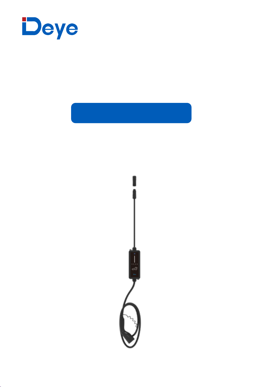
SUN-EVSE��K��-EU-AC
SUN-EVSE��K��-EU-AC
User Manual
EV AC Charger

Contents
All Rights Reserved .............................................................................................................01
About This Manual .........................................................................................................01-02
1 Safe Introduc�ons ............................................................................................................ 03
2
Introduc�on.................................................................................................................04-06
2
.1 Introduc�on of installa�on methods
2 .2 Model
2 .3 Appearance and Dimensions
2 .4 System Topology
3
Installa�on ..................................................................................................................07-09
3
.1 Installa�on
3 .2 Unpacking and Inspec�on
3 .3 Installa�on Tool
3.4 Recommended specifica�on of AC cable and PE
3.5 Single phase connec�on
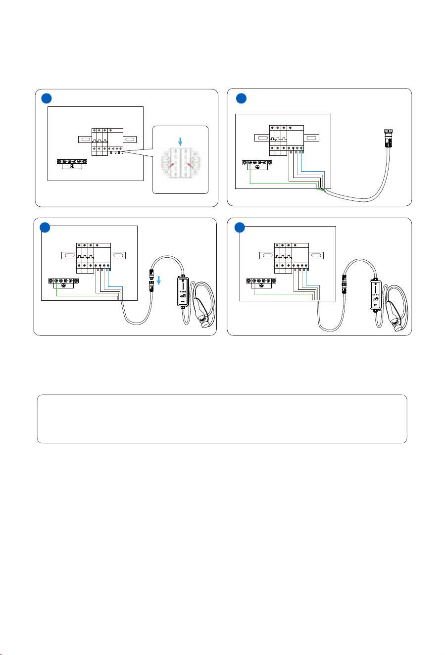
3 .6 Three phase connec�on
4 Inspec�on before Commissioning...............................................................................10-11
5 WiFi and Lora configura�on
........................................................................................12-24 5 .1 WiFi configura�on
5 .1.1 WIFI configura�on via APP
5 .1.2 WIFI configura�on via localhost
5 .2.Lora configura�on
5 .2.1 Bind EV charger
5 .2.2 Adjustment of channel with
6 Se�ng of communica�on mode ...................................................................................... 25
7 Local control
mode......................................................................................................26-27 7 .1
Explaina�on of parameters
7.2 View opera�ng status via LCD
8 Remote control via
APP...............................................................................................28-35 8.1 Without
hybrid inverter
8.2
With hybrid inverter
9 Troubleshoo�ng ..........................................................................................................36-37
10 Technical Data ...........................................................................................................38-39
11 EU Declara�on of Conformitya.......................................................................................39

All Rights Reserved
All Rights Reserved
No part of this document can be reproduced in any form or by any means without the prior wri�en
permission of Ningbo Deye Inverter Technology Co., Ltd. (hereina�er "DEYE").
About This Manual
The manual mainly contains product informa�on, as well as guidelines for installa�on, opera�on, and
maintenance.
Trademarks
DEYE and other DEYE trademarks used in this manual are owned by DEYE.
All other trademarks or registered trademarks men�oned in this manual are owned by their respec�ve
owners.
Software Licenses
• It is prohibited to use data contained in firmware or so�ware developed by DEYE, in part or in full, for
commercial purposes by any means.
• It is prohibited to perform reverse engineering, cracking, or any other opera�ons that compromise the
original program design of the so�ware developed by DEYE.
Disposal
A�er the service life of the charger ends, please dispose of it in accordance with the applicable electrical
waste disposal act at the installa�on loca�on. It can also be returned to Ningbo Deye Inverter Technology
Co., Ltd., but the relevant expenses shall be borne by your party.
Privacy Protection
• Informa�on contained in this manual is the private property of Ningbo Deye Inverter Technology Co.,
Ltd. No part of this manual may be transmi�ed in any form without the prior wri�en permission of Ningbo
Deye Inverter Technology Co., Ltd. Internal reproduc�on is allowed only for product evalua�on or other
appropriate purposes.
• We declare that the network account and password data stored in the device system shall be used solely
for the remote control and monitoring of the device, and shall not be transmi�ed to any third-party data
pla�orm without the user's permission.
• At our EV charger, we take the privacy of our customers seriously. We only collect charging informa�on
in accordance with applicable privacy laws and regula�ons.
- 01 -
Target Group
This manual is intended for qualified technicians who are responsible for the installa�on, opera�on, and
maintenance of the charger, and end users who need to check charger parameters.
A qualified technician is required to meet the following requirements:
• Knowledge of electronics, electricity, and machinery, and be familiar with electrical and mechanical
schema�c diagrams.
• Training in the installa�on and commissioning of electrical equipment.
• Be able to quickly respond to hazards or emergencies that occur during installa�on and commissioning.
• Be familiar with local standards and relevant safety regula�ons of electrical systems.
• Read this manual thoroughly and understand the safety instruc�ons related to opera�ons.
EMC
In some cases, even if the equipment is in accordance with the standard emission limits, it can have an
impact in certain applica�on areas (some sensi�ve equipment is placed in the same loca�on; the
equipment is installed close to a radio or TV receiver), and the operator is obliged to take appropriate
ac�on to correct this situa�on.
How to Use This Manual
Please read this manual carefully before using the product and keep it properly in a place for easy access.
All contents, pictures, marks, and symbols in this manual are owned by DEYE. No part of this document
may be reprinted by the non-internal staff of DEYE without wri�en authoriza�on.
Contents of this manual may be periodically updated or revised, and the actual product purchased shall
prevail. Users can obtain the latest manual from [email protected].
Symbols
This manual contains important safety instruc�ons, which are highlighted with the following symbols, to
ensure personal and property safety during usage, or to help op�mize the product performance efficient-
ly.
DANGER
Indicates high-risk poten�al hazards that, if not avoided, may lead to death or serious
injury.
WARNING
Indicates moderate-risk poten�al hazards that, if not avoided, may lead to death or
serious injury.
CAUTION
Indicates low-risk poten�al hazards that, if not avoided, may lead to minor or moderate
injury.
- 02 -
�. Safe Introductions
This manual contains important instruc�ons for the charger that shall be followed during installa�on,
opera�on, and maintenance. Please review all warnings and no�ces before installing and using the
charger.
WARNING
Do not install or use the charger near flammable, explosive, harsh or combus�ble
materials, chemicals, or vapors.
WARNING
Turn off the power supply at the circuit breaker before installing or cleaning the charger.
NOTICE
• Use the charger only within the opera�on steps and parameters specified in this manual.
• Never spray water or any other liquid directly onto the charger body or the charging connector. Store
the charger in the connector socket to prevent unnecessary damage.
• Do not a�empt to disassemble, repair, tamper with or modify the charger. Contact DEYE for any repair
or modifica�on.
• Do not use the charger if it is defec�ve, appears cracked, frayed, broken or otherwise damaged, or fails
to operate. Please contact Deye in �me.
Be careful when transpor�ng the charger. Do not subject it to strong force or impact or pull, twist, tangle,
drag, or step on the charger to prevent damage to it or any components.
• Do not touch the end terminal of the charger with any part of your body or metal objects.
• Use of charger may affect or impair the opera�on of any medical or implantable electronic devices, such
as implantable cardiac pacemakers or implantable cardi overter defibrillator. Please check with your
electronic device manufacturer concerning the effects of the charger on such electronic devices before
using the charger.
- 03 -
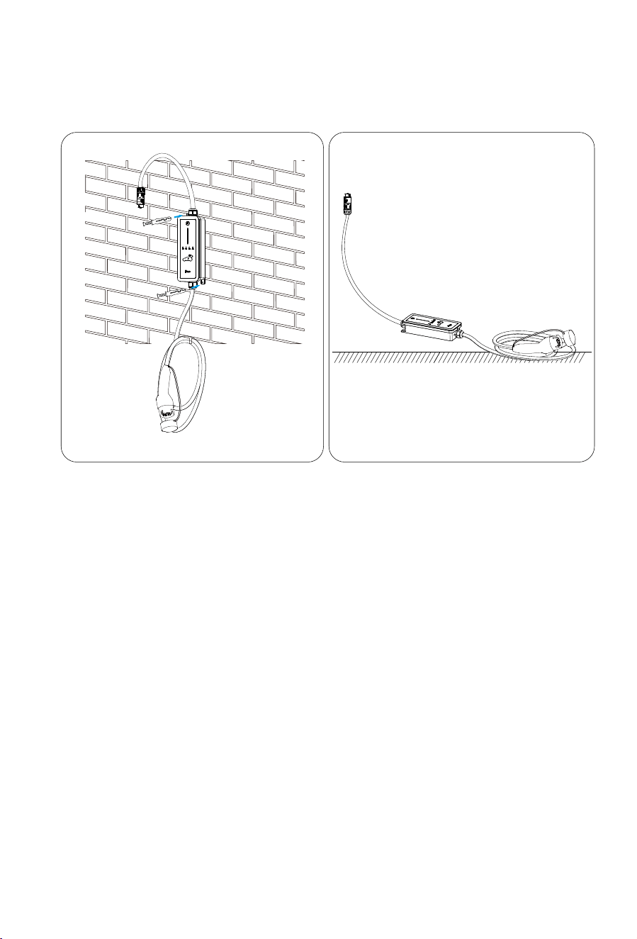
The charger is used for AC charging of electric vehicles (EV/PHEV) and can be wall-mounted or drag and
drop used.
�. Introduction
�.� Introduction of installation methods
�.� Model
The charger comes in two versions for different use cases:
· Ease of Use
EV drivers can start and stop charging via LCD screen of Deye hybrid inverter or App. When the vehicle is
fully charged, the charging will stop. The charger also supports plug&play charging, which means the
charging starts automa�cally as soon as the charging connector is plugged into the vehicle.
· Smart and Easy Management
In addi�on to the LED lights on the charger that indicate charging status, EV drivers can visualize and
control the charging session remotely via Deye cloud or Solarman.
· Sustainability
With an IP66 ra�ng, the charger is water and dust proof, allowing for outdoor use and maintenance.
SUN-EVSE11K01-EU-AC
SUN-EVSE22K01-EU-AC
- 04 -
drag and dropwall-mounted
�.� Appearance and Dimensions
��
�m
���
���
���
�.�m*
➀
➁
➂
➃
➄
➅
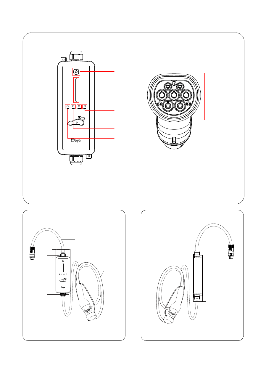
1:Func�on bu�on
2:LED strip
3:Alarm indicator
4:Normal indicator
5:Lora indicator
6:WIFI indicator
7:Charging connector
Type 2
- 05 -
➆
4.2 m*: The cable between the wall box and the plug is available in two lengths: 4.2 m (standard)
and 5 m (op�onal).
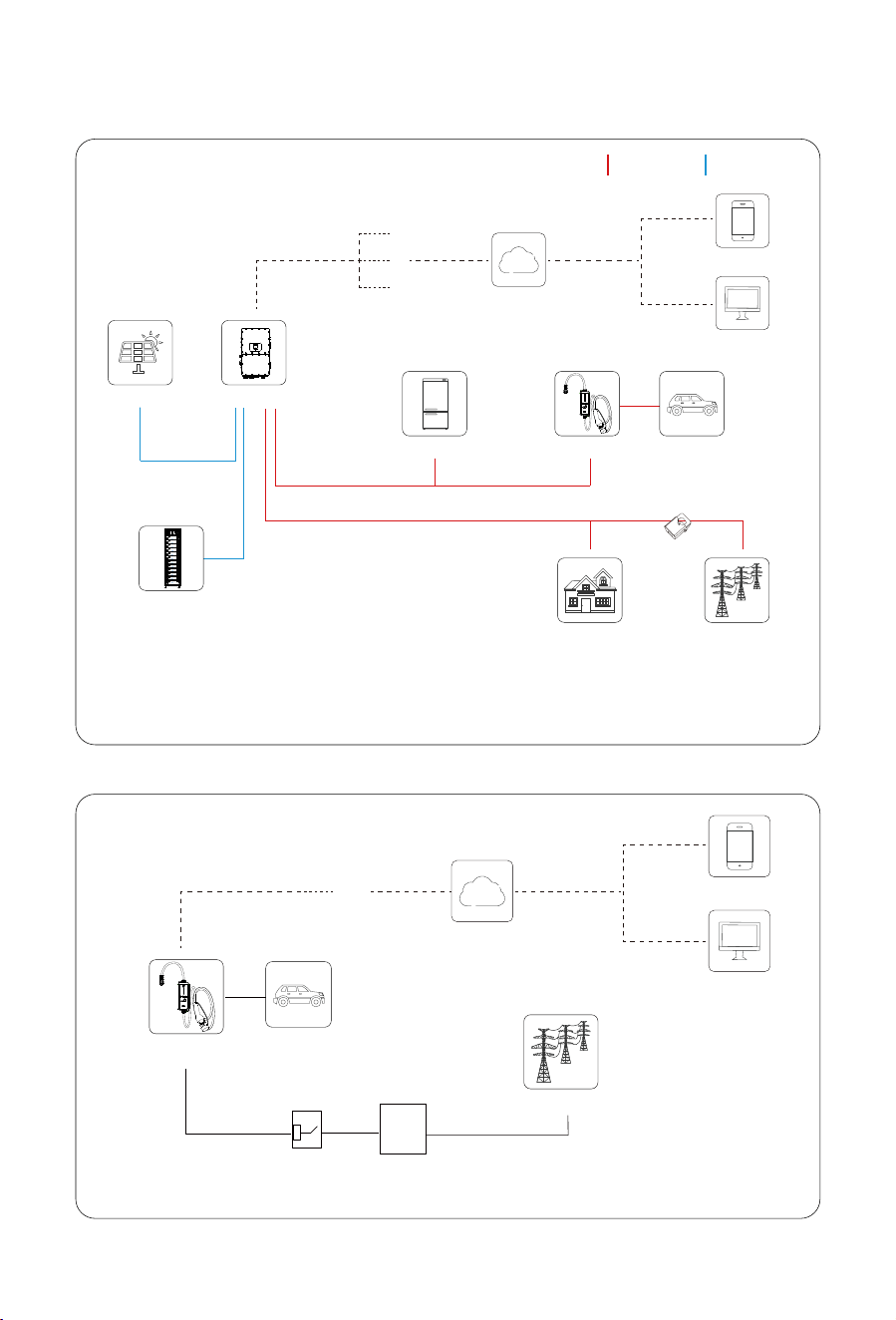
�.� System Topology
Hybrid Inverter
Charger
Solar
CT
AC cable DC cable
Battery
Backup Load
Grid
Home Load
Service
Web
App
Wi-Fi
4G
LAN
Car
Car
- 06 -
Charger
RCD
Sub DB
Main Distribution Box
Grid
Service
Web
App
Wi-Fi
With hybrid inverter
Without hybrid inverter
*EV charger can also be installed on the Grid port side of the hybrid inverter as a common load.
*When used together with a Deye hybrid inverter, the EV charger operates in LoRa control mode. Therefore, a
Smart TX must be installed on the hybrid inverter to enable communica�on and coordinated control. Please note
that not all Deye hybrid inverters support Smart TX installa�on. For compa�bility confirma�on, please consult t
he official Deye service team.
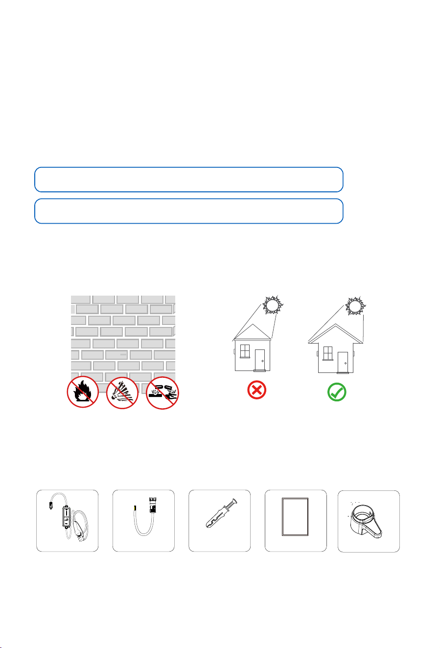
• Avoid exposure to direct sunlight.
• The charger should be well-ven�lated for good air circula�on.
• The moun�ng loca�on must be away from living area. The charger will emit noises during opera�on that
might be perceived as disturbing.
Recommended installa�on place
�.� Unpacking and Inspection
Check the equipment before installa�on. Please make sure nothing is damaged in the package.
You should have received the items in the following package:
User manual x1
User
manual
AC cable x1
PE
L1
L2
L3
N
�. Installation
�.� Introduction
· Location Requirements
Select an op�mal moun�ng loca�on for safe opera�on, long service life and expected performance.
· Environment Requirements
• There must be no flammable hazards or igni�on risks.
• The moun�ng loca�on must be inaccessible to children.
• The ambient temperature and rela�ve humidity must meet the following requirements.
Operating Temperature Range:-40 ~ +55℃
Permissible Ambient Humidity:5% ~ 95% No condensa�on
an�-collision bolt M4×80
x2
EV AC Charger x1
- 07 -
European Spear Seat x1
Sleeve M6*3
Expansion screw
M4*3
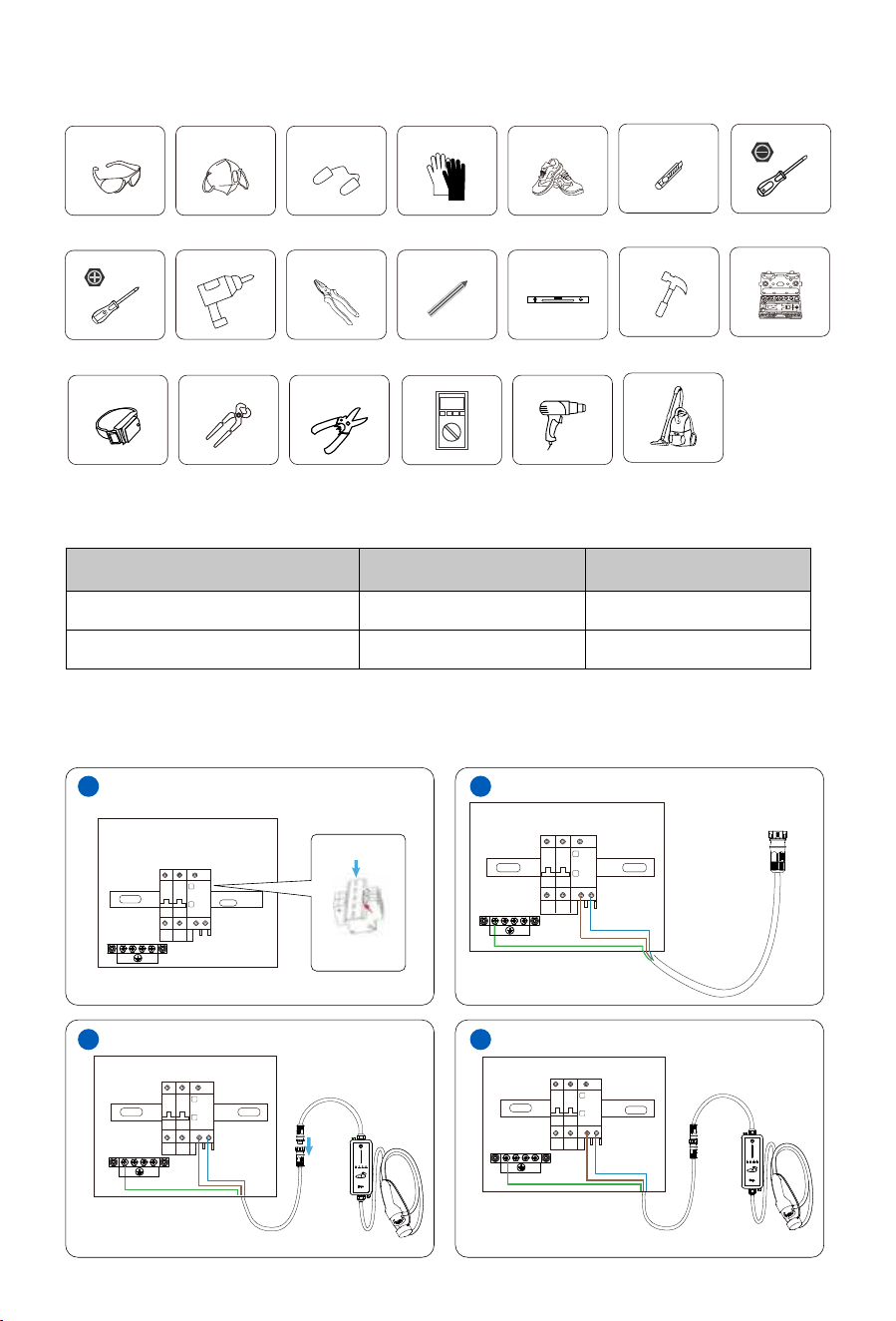
Protective goggles EarplugsAnti-dust mask Work gloves
Utlity Knife Slotted screwdriver
Cross screwdriver
Work shoes
Percussion drill
Anti-static wrist strap
Wire cutter
Wire stripper
Heat gun
Pliers
Marker
Level
Rubber hammer socket wrenches set
Multimeter ≥���� Vdc
�.� Installation Tools
Installa�on tools can refer to the following recommended ones. Also, use other auxiliary tools on site.
Cleaner
Recommended Size for AC Cable and PE
Model Wire Size Cross section
SUN-EVSE11K01-EU-AC 14AWG 1.5mm²
SUN-EVSE22K01-EU-AC 10AWG 4mm²
�.� Recommended specification of AC cable and PE
- 08 -
�.� Single phase connection
Distribution Box
� �
� �
RCD
N
N
N
L�
L�
L�
PE
PE
PE
- 09 -
�.� Three phase connection
Distribution Box
� �
RCD
�
L� L� L� N L� L� L� N
L� L� L� N
PE
PE
PE
Note: When using in single-phase mode, you must use L1 + N (the insula�on sheath of L1 phase is brown,
and the insula�on sheath of N line is blue).
Note: Please wire according to the phase sequence: the insula�on of phase L1 is brown, the insula�on
of phase L2 is black, the insula�on of phase L3 is gray, the insula�on of N line is blue, and the insula�on
of PE ground line is yellow-green.
�
The charger already integrates a DC residual-current device (RCD) with a rated residual-current of 6
mA. However, the charger also requires a type A RCD of 30 mA to operate. Each charger in the
system must be individually connected to the u�lity grid through an RCD and a miniature circuit
breaker.
NOTICE
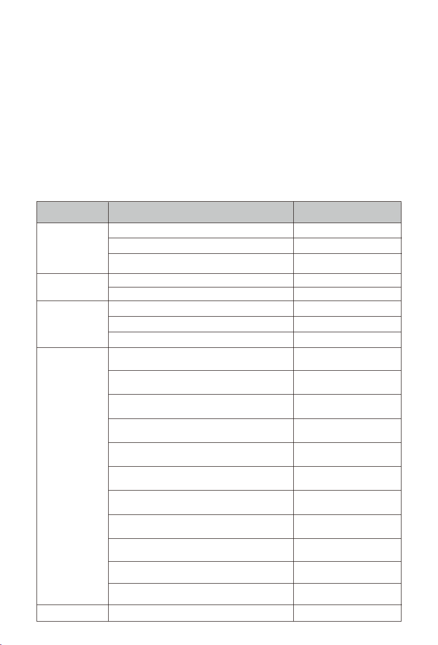
Indicator
Status
Meaning
Always on
Blink once per second WiFi (Green LED)
OFF
OFF
Blink once per second
In wifi mode and wifi communication
is normal
In LoRa mode and wifi communication
is normal
�、No wifi communication
�、Wifi indicator is damaged
LoRa communication is normal
�、No LoRa communication
�、LoRa indicator is damaged
No alarm occured
EV charger is unnormal, like the
power supply is interrupted
F� overcurrent fault occurred
F� overvoltage fault occurred
F� undervoltage fault occurred
F� leakage current fault occured
F� Short circuit occured in the
guiding circuit
F� Relay fault occured
F� Charging circuit fault occured
F� Overtemperature fault occured
F� Low temperature warning
F�� Grounding fault
Normal indicator blink one time
→Alarm indicator blink
ten times
→Normal indicator blink one time again. Cyclic
NormalOFF
LoRa (Green LED)
ON
OFF
A malfunction has occurred
Blink one time during the intervals of the alarm light cycle
Normal (Green LED)
Normal indicator blink one time
→Alarm indicator blink
one time
→Normal indicator blink one time again. Cyclic
Normal indicator blink one time
→Alarm indicator blink
two times
→Normal indicator blink one time again. Cyclic
Normal indicator blink one time
→Alarm indicator blink
three times
→Normal indicator blink one time again. Cyclic
Normal indicator blink one time
→Alarm indicator blink
four times
→Normal indicator blink one time again. Cyclic
Normal indicator blink one time
→Alarm indicator blink
five times
→Normal indicator blink one time again. Cyclic
Normal indicator blink one time
→Alarm indicator blink
six times
→Normal indicator blink one time again. Cyclic
Normal indicator blink one time
→Alarm indicator blink
seven times
→Normal indicator blink one time again. Cyclic
Normal indicator blink one time
→Alarm indicator blink
eight times
→Normal indicator blink one time again. Cyclic
F�� Lora communication fault
Normal indicator blink one time
→Alarm indicator blink
eleven times
→Normal indicator blink one time again. Cyclic
Normal indicator blink one time→Alarm indicator blink
nine times
→Normal indicator blink one time again. Cyclic
Alarm(Red LED)
Note: From F� to F��,
the priority decreases
sequentially. When
multiple faults occur
simultaneously, the
fault code with the
highest priority will
be displayed.
- 10 -
�. Inspection before Commissioning
· Location
The charger is correctly mounted at a place that is convenient for opera�on and maintenance.
· Charger
The charger is firmly and securely installed.
· Cable
Cables are correctly and firmly connected, and are adequately protected from damage.
· Clearance
The charger has sufficient cooling space and there is no other stuff or components are le� on the top of the
charger.
1. Ensure that all requirements are met before commissioning.
2. Power on the charger.
3. Check the status of the indicators and confirm if this EV charger is opera�ng properly.
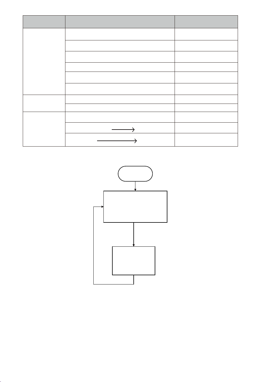
- 11 -
Indicator
Status
Meaning
Charging in 'plug and play' mode
LED strip(tri-color LED)
Displaying a blue breathing light effect
Charging in 'Time of charge' modeDisplaying a green breathing light effect
Function button
LED strip:Blue/Green
Short press the button
Press and hold the button for at least � second until the
LED strip turns purple.
LED strip:Red
LED strip turns Red
LED strip turns
back to Blue/Green
Buzzer
Any faulty occuringMake a sound
Normal
Not making any sound
UpdatingDisplaying a white breathing light effect
Displaying a Purple breathing light effect
Emergency stop
(The relays will disconnect)
Red LED light is on
idle or A malfunction has occurred
Emergency stop
Restore to the previous working
state
Enter channel scanning mode
Enter channel scanning mode
OFF
Short press the button
Start
Emergency stop
(LED strip:Red)
Plug and play mode or
Time of charge mode
(LED strip:Blue/Green)
Short press
the function button
Short press
the function button
16:53
62
德业变频...
Please enter a plant name Filter
Power
--
Capacity
55.00
kWp
上海(UTC-05:00)
Updated Unknown
ccccccaaaaaa
Online
Power Capacity
1.00
kWp
0.00
W
德业科技股份有限公司(UTC+01:00)
Updated 1mins ago
Plant Device Me
Normal
63
16:54
HD
Create a Plant
WI-FI Configuration
Local Mode
Data Migration
Migration Progress
�
In scenario without hybrid inverter, only WiFi configura�on is required. In scenario with hybrid inverter,
both WiFi configura�on and LoRa configura�on are required.
This series EV charger has built-in WIFI module(with Bluetooth func�on) which is able to connect
router directly. For WIFI configura�on, the following two methods are recommended.
�.WiFi and Lora configuration
�.� WiFi configuration
�.�.� WiFi configuration via APP
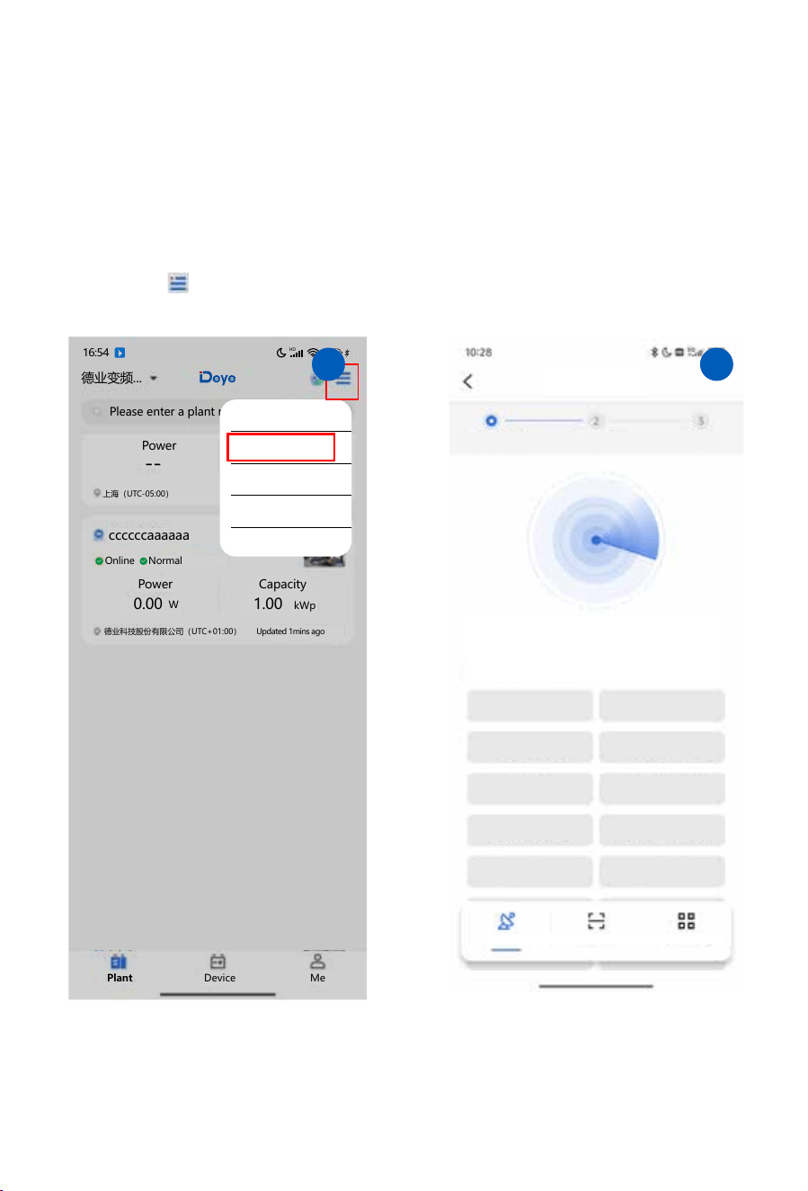
Step 1: Tap on “ ” icon in the upper right corner of Deye cloud APP, select “Wi-Fi configura�on” and
automa�cally jump to the page for scanning nearby devices;
Scan Devices
Add a Device
Config Device Done
Scanning nearby devices
Nearby devices(24)
AP_381927
AP_383354
AP_382547
AP_383547
Scan
QR code Add manually
AP_383578
AP_3636354 AP_3837868
AP_353454
AP_3422688527
AP_383545
- 12 -
�
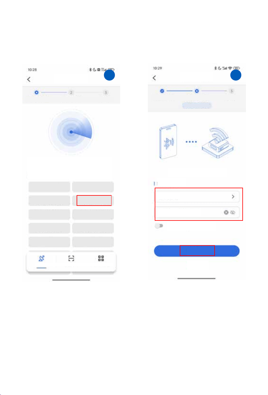
Step 2: Select the AP hotspot of EV charger's built-in WiFi module;
Step 3: Select an available 2.4G network, enter it’s password and tap on “Next” ;
Scan Devices
Add a Device
Config Device Done
Scanning nearby devices
Nearby devices(24)
AP_381927
AP_383354
AP_382547
AP_383547
Scan
QR code Add manually
AP_383578
AP_3636354 AP_3837868
AP_353454
AP_3422688527
AP_383545
SN:3422688527
Deye-TEST
........
WIFI has no password
Next
Back
Select WIFI
Please use 2.4G WIFI network
Config Device
Add a Device
Config Device Done
- 13 -
� �
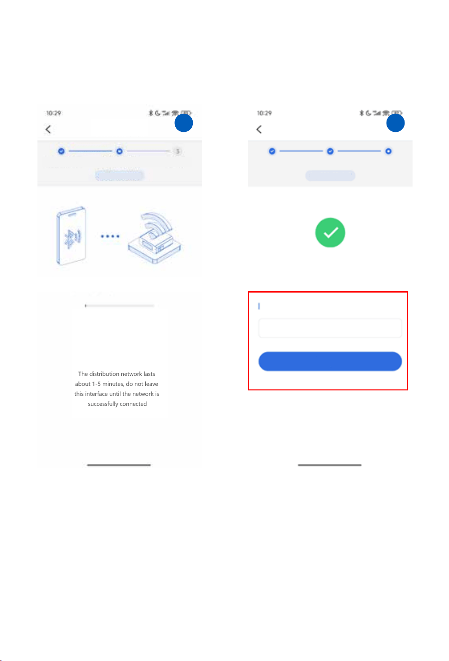
Step 4: Wi-Fi configura�on is in process (Please don’t leave this page and place your
phone near the devices);
Step 5: A�er Wi-Fi configura�on done, you could enter a personalized device name and
tap on “Complete” to end the configura�on.
SN:3422688527
Config Device
Add a Device
Config Device Done
Please place your phone near the devices
16s
The distribution network lasts
about 1-5 minutes, do not leave
this interface until the network is
successfully connected
SN:3422688527
Done
Add a Device
Config Device Done
WIFI configured successfully
Please enter a personalized device name
Complete
- 14 -
� �
- 15 -
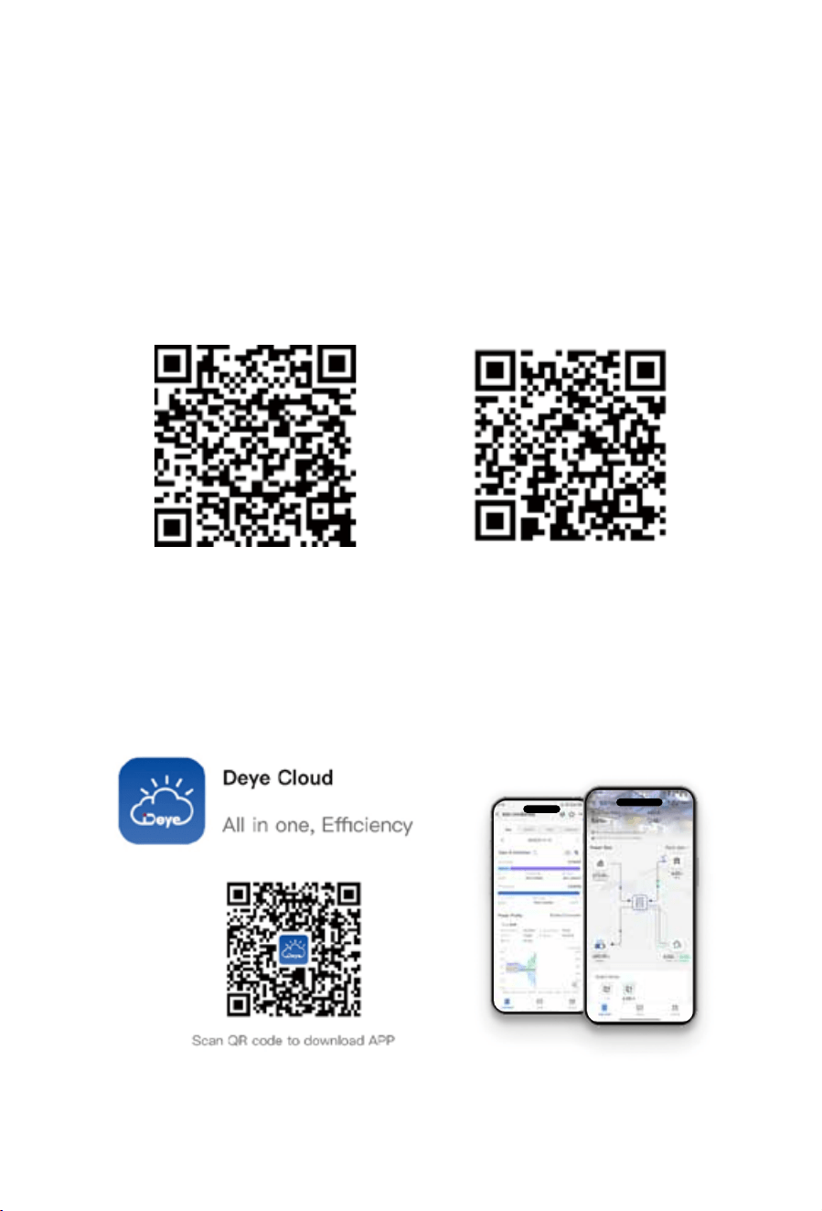
Webpage monitoring address: h�ps://www.deyecloud.com.
For mobile phone monitoring system, scan the QR code below to download the APP.
Also you can find it by searching “deye cloud” in App store or Google Play store.
�.�.� WiFi configuration via localhost
SOLARMAN Smart
for end user
SOLARMAN Business
for distributor/installer
Web monitoring addresses:
h�ps://pro.solarmanpv.com (for Solarman distributor accounts)
h�ps://home.solarmanpv.com (for Solarman end-user accounts)
To use the mobile monitoring system, scan the QR code to download the corresponding APP.
You may also search for solarman business on the App Store or Google Play Store; this APP is intended for
distributors and installers.
Search for solarman smart on the App Store or Google Play Store and select the app of the same name; this
APP is designed for photovoltaic system owners.
Method 1:
Method 2:
ON
0
15
0.00
kW
0.00
kW
0.09
28%
kW
0.03
kW
0 12
0
12 0 12
01/08/2025 12:32:40
Wed
Off grid
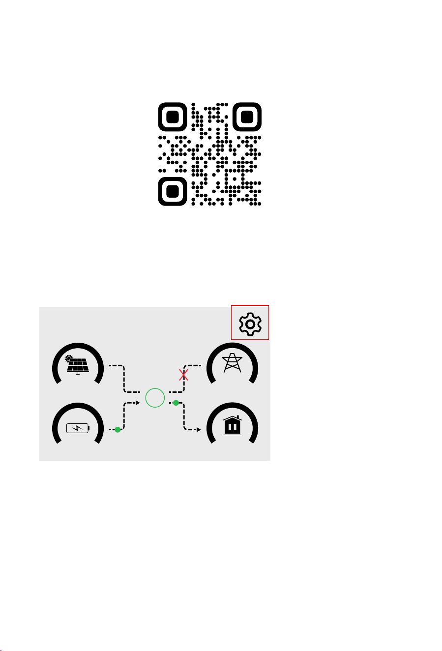
1. Enter the Main screen of inverter’s LCD.Click on the gear icon in the upper right
corner of the screen to enter the ‘System Setup’ page.
�.�.Lora configuration
�.�.� Bind EV charger
- 16 -
Method 1:
For this method, please scan the QR code below to download the corresponding Deye Cloud reference
document.
Note:In scenario without hybrid inverter, a�er comple�ng WiFi configura�on, you can directly jump to
sec�on 8.1 to check how to monitor and manage the EV charger via the APP.
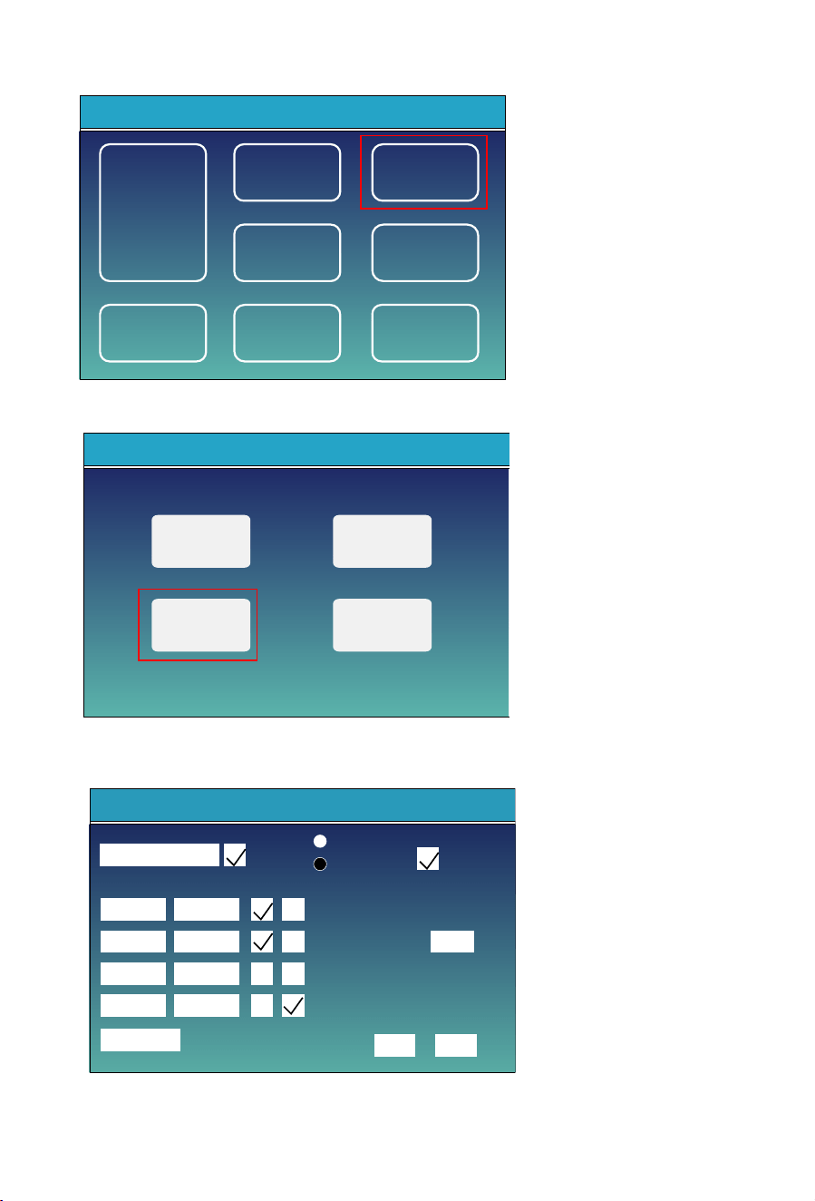
System Setup
Work Mode
Grid Setting
Advanced
Function
Device Info
Gen Port
Use
Smart Devices
Battery
Setting
Basic
Setting
2. Click on the ‘Smart Devices’ item on the ‘System Setup’ page to enter the ‘Smart Devices’ page.
3. Click on the ‘Smart EV Charge’ icon to enter the parameters page of EV Charger.
Smart Devices
Smart CT
Smart Switch
Smart EV Charge
Smart TX
- 17 -
4. Click the long textbox before the "Enable" checkbox to enter the 'SN input' page.
SN Input
SN:2024103294
05:30
08:10
20:35
22:35
3000W
ESC OK
08:10
20:35
22:35
>20%
05:30
Start Time End Time Charge
Solar energy only(SOC>95%)
Free work
Plug and play
Time of charge
Enable
Off grid EV Charge off
Off grid
SOC
EV_charge device connect at Grid port
EV_charge device connect at LD port
Max charge power
- 18 -
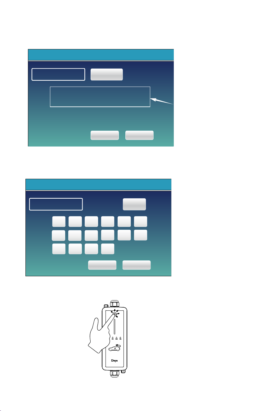
5. Click the 'Edit SN' bu�on and then click the 'OK' bu�on on the 'SN input' page, the so� keyboard will
display on the screen for you to type in the serial number (SN) of the EV charger, its series number can
be found on its label.
6.A�er comple�ng the input and confirming it is correct, click "OK" to save the se�ng; click the "DEL" bu�on
to delete incorrect data, and click the "CANCEL" bu�on to cancel edi�ng and exit, meanwhile check the enable
checkbox behind the text box and then scan the charging pile channels a�er exi�ng the edit page.
7.Press and hold the bu�on for at least 1 second un�l the LED strip turns purple to enter
channel scanning mode. A�er successful channel scan, the LoRa indicator blinks once per second.
SN Input
SN Input
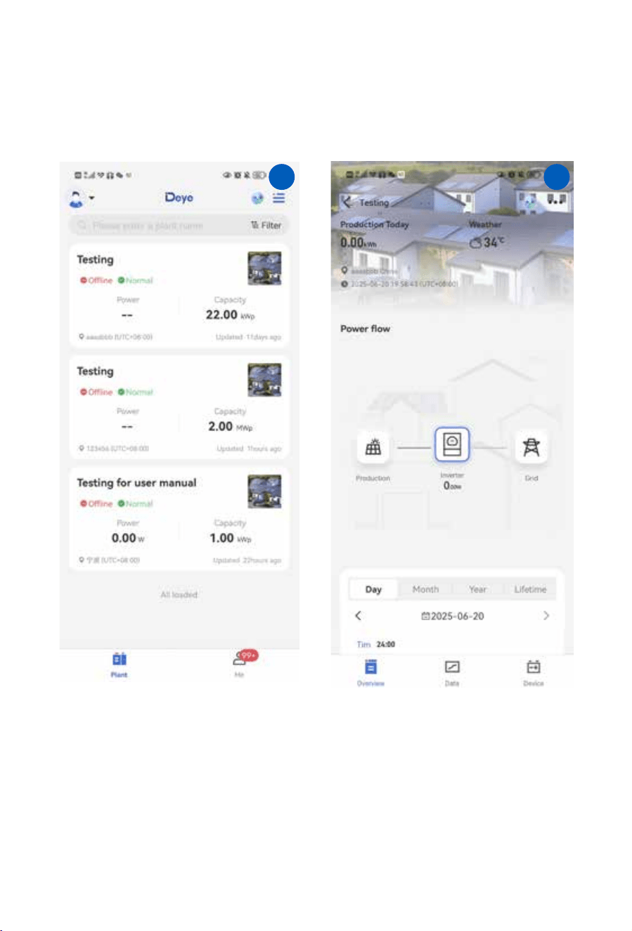
1. Click on the plant that needs to add an "EV Charger"
on the plant listpage to enter the "Overview" page
of the plant
2. Click on the "Device" item in the bo�om
right corner of the"Overview" page to enter
the "Device" page
- 19 -
� �
Method 2:
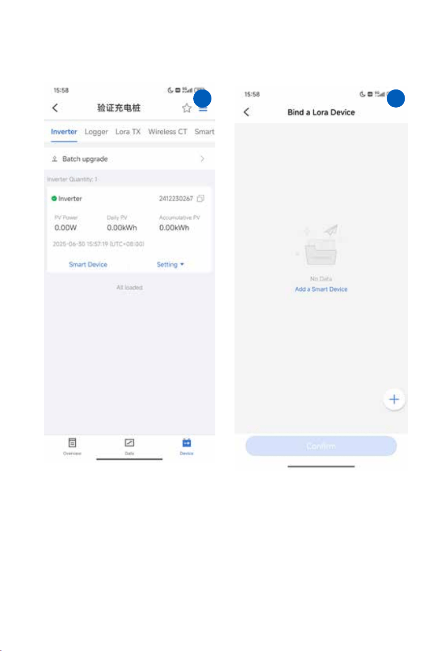
3. Click on the blue "Smart Devices" item in the
middle of the"Inverter" page to enter the "Bind
a Lora Device" page
4. Click on the "+" icon in the bo�om right
corner of the page to enter the"Scan SN" page.
- 20 -
� �
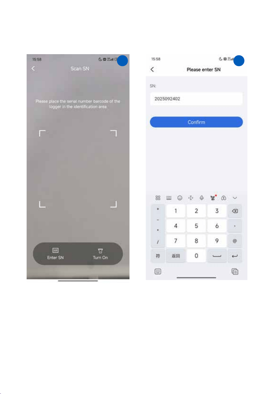
5. Scan the QR code corresponding to the SN
informa�on of the EV chargeraccording to the
prompts on this page. You can also click on the "
Enter SN" icon in the bo�om le� corner of the
page to enter the manual SN input page.
6. Manually enter the SN of the EV Charger,
then click the "Confirm" bu�onto confirm
and complete the input.
- 21 -
� �
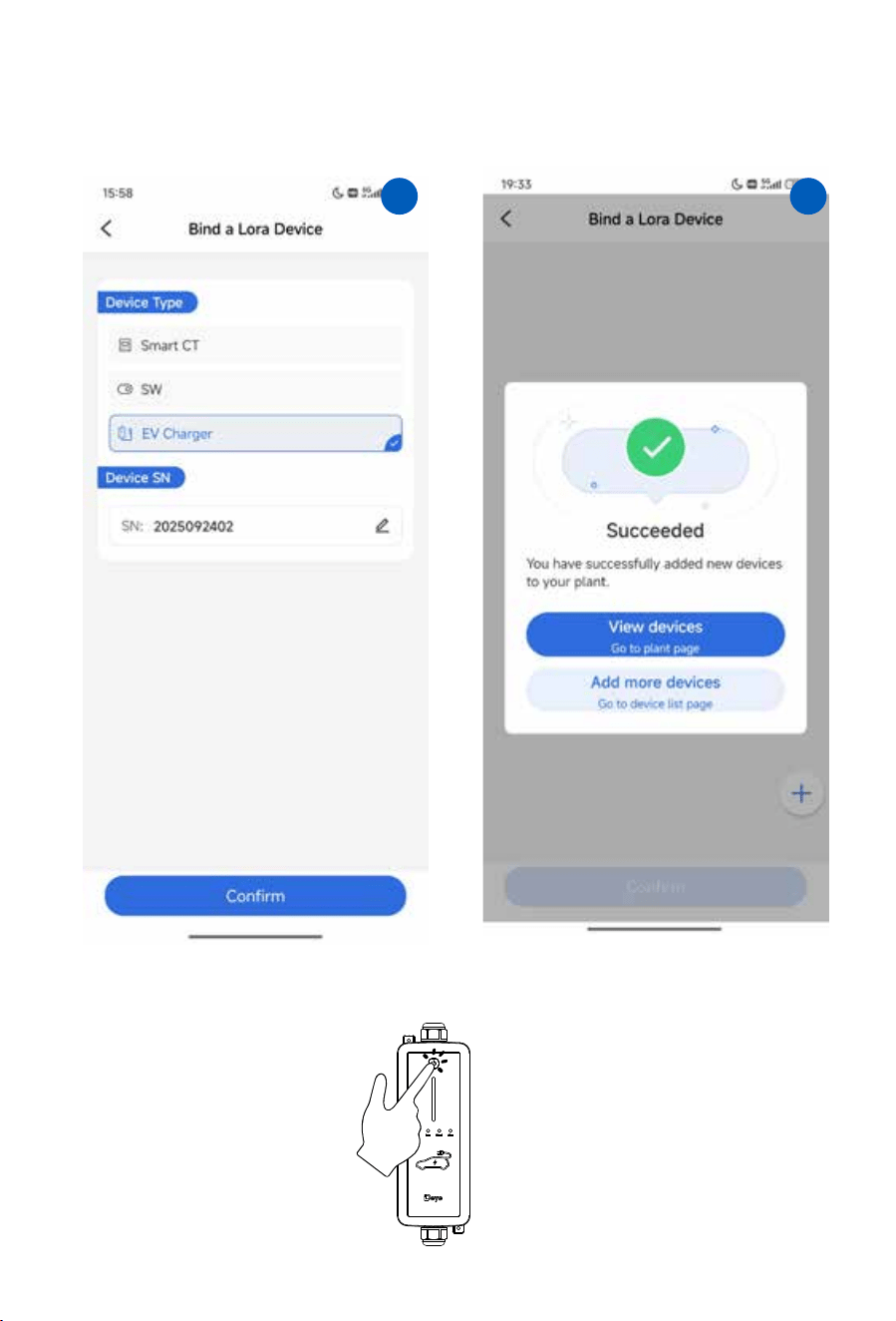
7.Select 'Device Type' as' EV Charger ', then
click the "Confirm" bu�on to confirm and
complete the binding.
8.A�er comple�ng the binding, the following
message will pop up indica�ng successful
binding.
- 22 -
� �
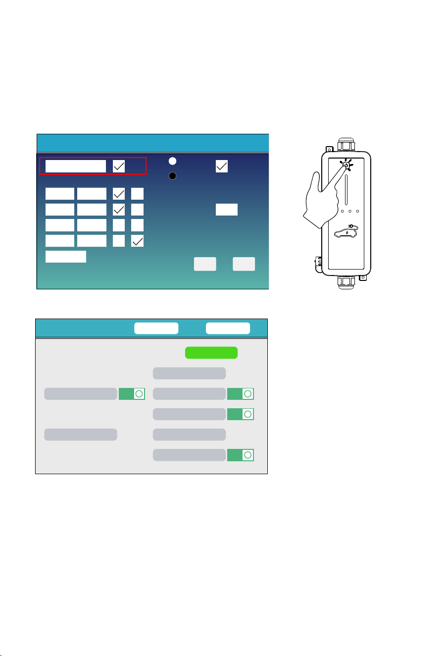
9. Refer to Step 7 on page 17 to perform a channel scan on the EV charger.
- 23 -
Smart Devices
CANCEL OK
switch2 0.00KW
ON
I
switch7 0.00KW
ON
I
switch8 0.00KW
ON
I
switch10 0.00KW
ON
I
switch4 0.00KW TM-OFF
switch6
EV: 0.00KW
0.00KW TM-OFF
switch9 0.00KW TM-ON
Method 1:A�er correctly inpu�ng the SN of the EV charger and enabling the charger (as shown in Figure 5.2-1)
, press and hold the bu�on (as shown in Figure 5.2-2) on EV charger body un�l its LED strip turns
purple to enter channel scanning mode. A�er channel search completed, the purple breathing light effect
of the LED strip will disappear, LED strip will return to the previous status. On the 'Smart Devices' detail
informa�on page, the EV charger icon will be green (as shown in Figure 5.2-3).
Figure 5.2-1
Smart Devices
ESC OK
SN:2024103294
End-TimeStart-Time Charge
Enable
Plug and play
Free work
Solar energy only(SOC>95%)
EV_charge device connect at LD port
Off grid EV Charge off
EV_charge device connect at Grid port
Max charge power
Time of charge
05:30 08:10
08:10 20:35
20:35 22:35
22:35
05:30
3000W
Off grid
SOC
>20%
Figure 5.2-2
Figure 5.2-3
Enable the EV charger, then adjust the communica�on channel of the EV charger or smart TX01
or conduct communica�on channel scanning to build the LoRa communica�on between hybrid
inverter and EV charger
�.�.� Adjustment of channel
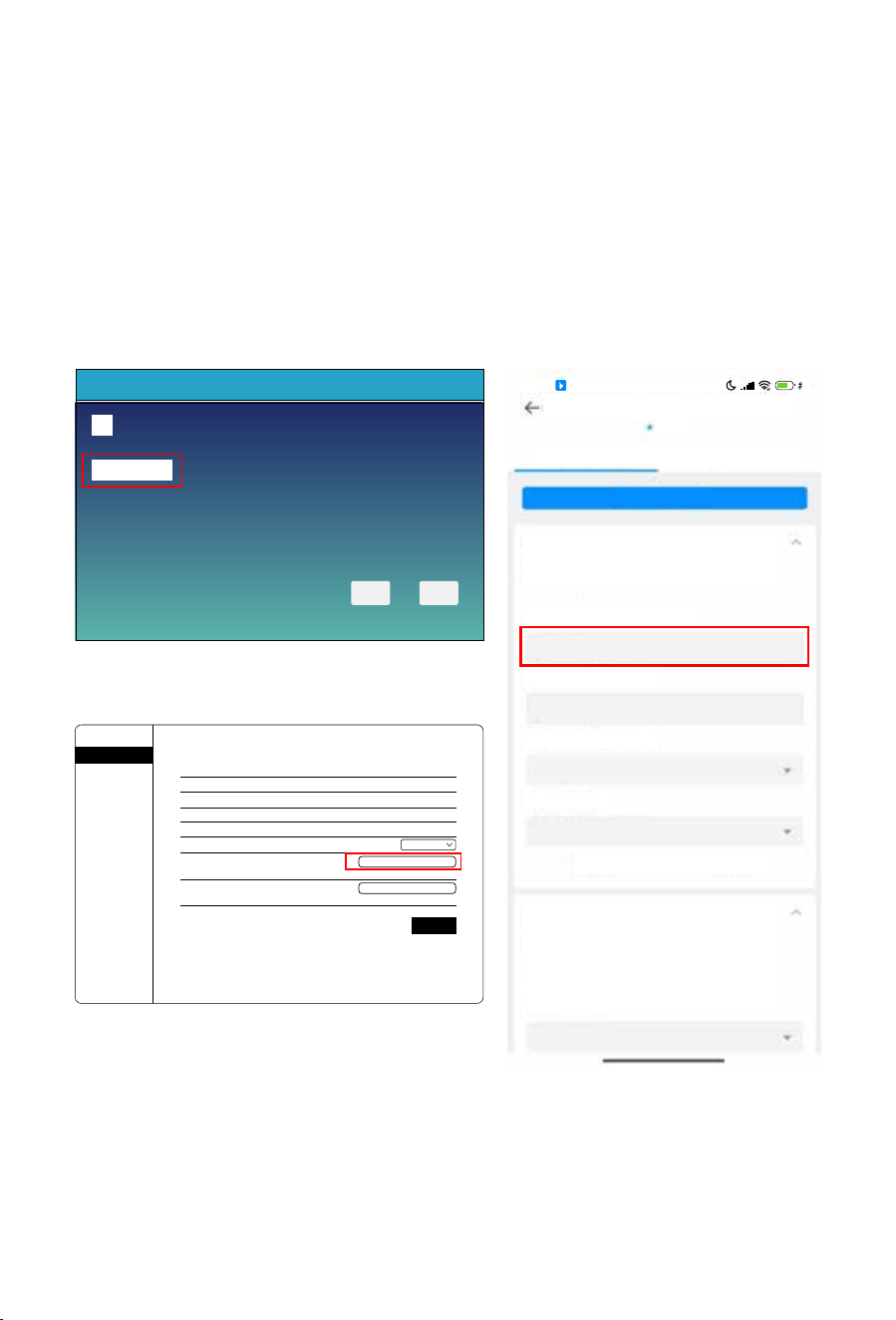
Figure 5.2-4
Figure 5.2-6
Reset Smart TX
Channe1:0
Smart Devices
ESC OK
63
16:54
HD
CHARGING_STATION:E24C0501FF
Online
Control Log
Batch Command
Charging Pile Foundation Configuration
Classification
Read from2025/01/14 16:55:04 UTC+08:00
Read
Frequency of Communication
Successfully
4
Frequency of Upgrade
0
Restore factory setting
Default
System Time
2022/01/14 16:55
Read
Setup
Charging Station Disconnected From
Gateway
Read from2025/01/13 19:03:40 UTC+08:00
Read
Failure
off grid SW off
Please Select
Figure 5.2-5
Wizard
Status
Quick Set
Advanced
Upgrade
Restart
Reset
Inverter serial number
Power L1
Power L2
Power L3
Working mode 1
Working mode 2
Lora communica�on frequency
Charging power upper limit
Device informa�on
Remote server informa�on
Inverter informa�on
E25219021F
0W
0W
0W
Plug and play
Lora
4
(0-9)
(0-22000W)
Save
6000
-
+
+
- 24 -
There are several ways to adjust the Lora communica�on channel of EV charger:
Method 1: Adjust the communica�on channel of smart TX01 via the LCD display of the hybrid inverter (as
shown in Figure 5.2-4) to make it consistent with the default LoRa communica�on channel (Usually it's
6) of the EV charger.
Method 2: Adjust the LoRa communica�on frequency of the EV charger to match the channel of the
smart TX (default is 6) via the EV charger's built-in WiFi module's Localhost(as shown in Figure 5.2-5),
please refer to chapter 5.1.2 for the method of entering the localhost of EV charger.
Method 3: In wifi mode, set the LoRa communica�on frequency of the EV charger to match that of the
smart TX (default is 6) via the APP's Remote Control page (as shown in Figure 5.2-6).
This EV charger has two kinds of communica�on mode: WiFi mode and Lora mode.
WiFi mode: Using the built-in WiFi module of EV charger, upload the opera�onal data of EV charger to
the cloud pla�orm directly, or send command to the EV charger through the cloud pla�orm's webpage.
Lora mode: Pair the built-in Lora module of EV charger with the smart TX master node of the
hybrid inverter, and then upload the opera�onal data of EV charger or receive the control commands
through the Lora module of EV charger. This is the default communica�on mode.
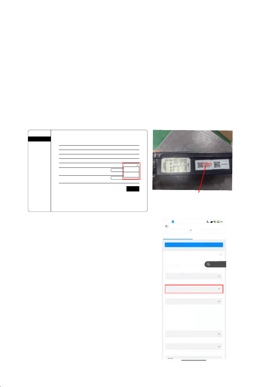
There are following several methods to switch the communica�on modes:
Method1: Switch the communica�on mode through the localhost of EV charger's built-in WiFi module.
step 1: Refer to chapter 5.1 to complete the WiFi configura�on.
step 2: Use the mobile devices like smart phone or laptop to connect the AP hotspot of EV charger,
the name of the AP hotspot is like AP_***(*** means SN of EV charger's WiFi module, as shown in
figure 6.1).
step 3: Log in the localhost of EV charger's AP hotspot:10.10.100.254, user name: admin,
password: admin.
step 4: You can select the desired communica�on mode from the drop-down list of the "Working
mode 2" sub item on the "Status" page, as shown in Figure 6.2
Method 2: Switch the communica�on mode through the
webpage or APP of the cloud pla�orm, as shown in Figure 6.3
Method 3:The other communica�on mode switching
methods, like through LCD of the hybrid inverter, are s�ll
under development.
As shown below, different scenarios support different
communica�on modes:
Scenario 1:No hybrid inverter, connect to other AC power
sources for separate use. In this scenario, only support WiFi
mode, but due to the default communica�on mode is lora
mode, it's necessary to first change the communica�on
mode through the aforemen�oned method 1.
Scenario 2:Connect to the Grid/Load port of the hybrid
inverter. In this scenario, both WiFi mode and Lora mode are
supported.
�.Setting of communication mode
Wizard
Status
Quick Set
Advanced
Upgrade
Restart
Reset
Inverter serial number
Power L1
Power L2
Power L3
Working mode 1
Working mode 2
Lora communica�on frequency
Charging power upper limit
E25219021F
0W
0W
0W
Plug and play
WIFI
5
(0-9)
(0-22000W)
Save
6000
WIFI
Lora
Device informa�on
Remote server informa�on
Inverter informa�on
-
+
+
63
16:54
HD
CHARGING_STATION:E24C0501FF
Online
Control Log
Batch Command
Charging Pile Working Mode
Classification
Read from2025/01/14 16:55:04 UTC+08:00
Read
Working Mode
Successfully
Appointment For Charging
Equipment Working Mode
Lora mode
Priority Activation Of Photovoltaic Charging
Enable
Freedback
charge1
charge2
charge3
charge4
Working Time Point 1
21:6
Working Time Point 2
22:8
Working Time Point 3
- 25 -
SN of WIFI module
Figure 6.1
Figure 6.2
Figure 6.3
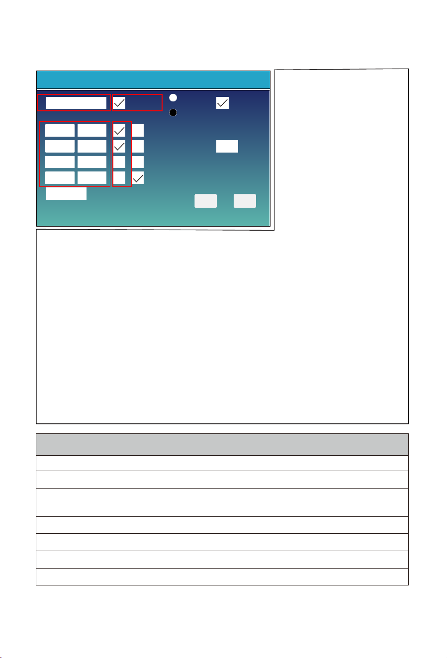
�.� Explaination of parameters
Set the parameters of EV charger on the LCD of the inverter
➀: Type the SN number of EV charger into the textbox in zone �.
➁ :Check or uncheck to enable or disable the EV charger.
➂: Check or uncheck to determine whether to use the EV charger to charge the EV
during the current time period or not.
➃:The start time of the first time period and the end time of the fourth time period.
➄:The start time of the second time period and the end time of the first time period.
➅:The start time of the third time period and the end time of the second time period.
➆:The start time of the fourth time period and the end time of the third time period.
Click on 'Smart EV charge' item in the
down le� corner of 'Smart Devices' page
to enter the le� page.
A�er checking the CheckBox in the upper
le� corner of the page, you can follow
the steps below to enter the series
number of the EV charger.
Plug and play: The EV charger will operate
like a common load, without the need to
follow programmable schedule se�ngs.
Time of charge: Control the use of EV
charger according to the programmable
schedule. 24 hours a day will be divided
into four �me periods (only the fourth
period can pass midnight), and whether
to use the EV charger to charge the electric vehicle during each �me period can be controlled separately.
Solar energy only(SOC>95%): Only when the SOC of the ba�ery rises to 99%, the excess solar energy from the
hybrid inverter can be used to power the EV charger. If the SOC of the ba�ery drops below 95%, the EV charger
will shut down.In addi�on, even without sufficient solar energy, the minimum charging current of EV charger
will be limited to 6A.
Free work: The AC power output from the inverter module (from solar power and ba�ery discharging power) and
the AC power input from the bypass circuit can both be used to power the EV charger.
O grid EV Charge o: When the hybrid inverter switches to off-grid mode and the SOC of the ba�ery isn't bigger
than the set value of 'Off grid SOC', the EV charger will be automa�cally turned off.
O grid SOC: When the hybrid inverter switches to off-grid mode, the EV charger will keep opera�ng if the SOC of
the ba�ery is bigger than this set value.
EV_charge device connect at Grid port: The EV charger is connected to the Grid port of the hybrid inverter.
EV_charge device connect at LD port: The EV charger is connected to the Load port of the hybrid inverter.
Max charge power: The maximum charging power allowed in both 'Plug and play' mode and 'Time of charge' mode.
In off-grid mode, the Max Charge Power of the EV charger cannot be set below 1000W when used in single-phase, and
below 4000W when used in three-phase.
Smart Devices
ESC OK
SN:2024103294
End-TimeStart-Time Charge
Enable
Plug and play
Free work
Solar energy only(SOC>95%)
EV_charge device connect at LD port
Off grid EV Charge off
EV_charge device connect at Grid port
Max charge power
Time of charge
05:30 08:10
08:10 20:35
20:35 22:35
22:35
05:30
3000W
Off grid
SOC
>20%
➀ ➁
➂
➃ ➄
➄ ➅
➅ ➆
➆ ➃
�.Local control mode
- 26 -
In Lora communica�on mode, the EV charger can work normally un�l the hybrid inverter has sent "Max charge power"
to the EV charger a�er star�ng or restar�ng it.
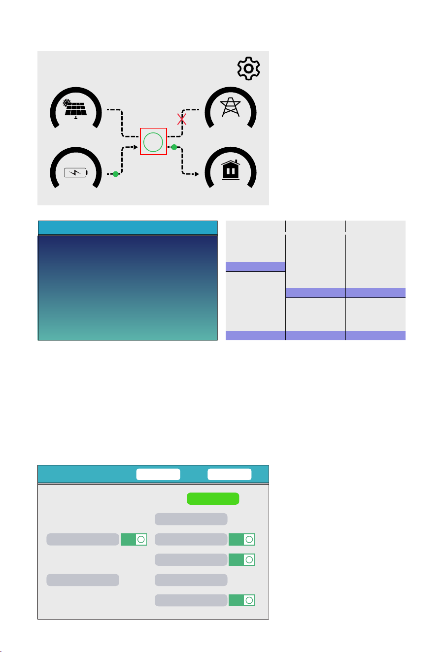
ON
0
15
0.00
kW
0.00
kW
0.09
28%
kW
0.03
kW
0 12
0
12 0 12
01/08/2025 12:32:40
Wed
Off grid
1. Click the circle on the center of LCD's main screen.
�.� View operating status via LCD
230V
27 W
10W
228V 0W
229V 10W
230V 0.0A
230V 0.0A
230V 0.0A
0W 10W
0.0 Hz
0 W
50.0 Hz
27 W
0W
0W
0W
0W
0W
DC_P1:
0W
DC_V1:
0V
DC_I1:
BAT_V:50.69 V
SOC:28%
94W
1.87 A
22.4 C
0.0A
DC_P2:
0W
DC_V2:
0V
DC_I2:
0.0A
7W
AC_T:
10W
41.0 C
0V
0.0A
0V 0.0A
0V
0.0A
HM: INV_P:
LD:
Load
Battery PV1 PV2
Grid Inverter
2. A�er the screen jumps to the page below,press the ‘UP’ or 'Down' bu�on to enter the next page.
Inverter
Power: -51W
50.0Hz
L1: 222V
I1: 0.8A
Three phase hybrid inverterSingle phase hybrid inverter
Smart Devices
CANCEL OK
switch2 0.00KW
ON
I
switch7 0.00KW
ON
I
switch8 0.00KW
ON
I
switch10 0.00KW
ON
I
switch4 0.00KW TM-OFF
switch6
EV: 0.00KW
0.00KW TM-OFF
switch9 0.00KW TM-ON
3. In this detail informa�on page of smart devices, you can check the opera�ng status of EV charger
at current �me. There are three scenarios as below:
(1)Normally opera�ng: the icon of EV in the upper right corner of this page is green and the charging
power at current �me is displaying.
(2)If the icon of EV in the upper right corner of this page is gray, which means the EV charger fails to
communicate with the inverter. Please back to the parameters se�ng page of EV charger to check
these items: Whether the SN of EV charger in text box is correct; Whether the EV charger has been
enabled. Whether the communica�ng channel of smart TX is channel 6(The default communica�ng
channel of EV charger is channel 6).
(3)Alarm : the icon of EV in the upper right corner of this page is red and the fault code is displaying.
- 27 -
�. Remote control via APP
- 28 -
�.� Without hybrid inverter (WiFi mode)
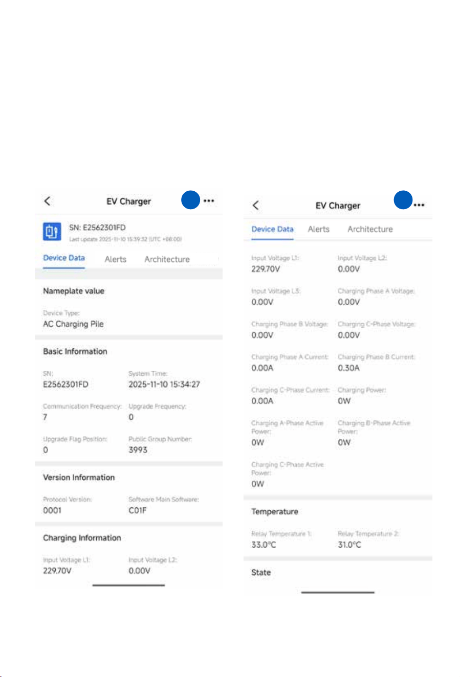
1. The APP page will redirect to the 'Device Data' page of the EV charger, where you can view all its
detailed informa�on.
A�er configuring the WiFi, find the EV charger to be managed in the device list, then follow the steps
below to operate it.
� �
- 29 -
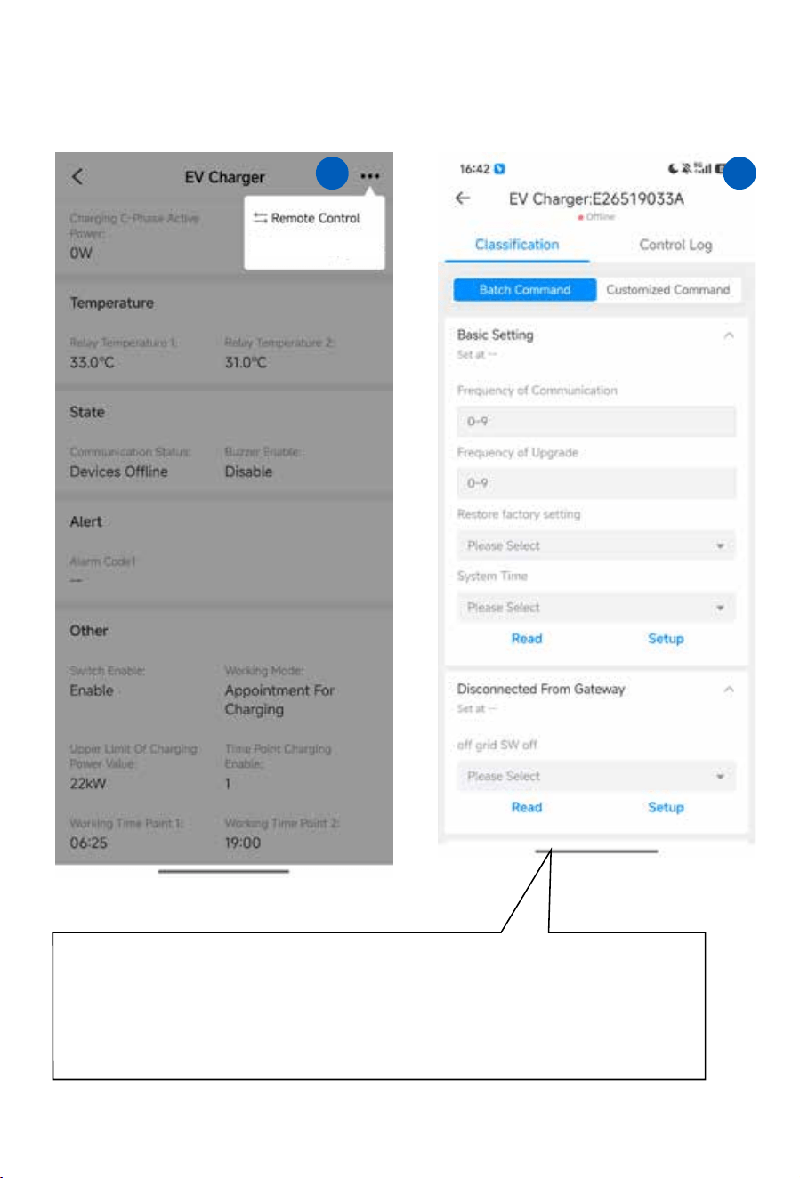
2. Click the '...' icon in the upper right corner of the page,
then select 'Remote control' from the dropdown menu.
3. There are two subordinate pages for Remote
control, and on the “Classifica�on” page,
you can set the parameters below .
Frequency of Communication: Choose the communica�on channel(frequency) for the EV charger to
communicate with Lora master of hybrid inverter.
Frequency of Upgrade: Choose which communica�on channel(frequency) to use to upgrade the firmware of
EV charger.
Restore factory setting: Restore all parameters of EV charger to the default values of the firmware.
System Time: Change the system �me of EV charger.
Off grid SW off: Automa�cally turn off the EV charger when the inverter switches to off grid mode.
� �
- 30 -
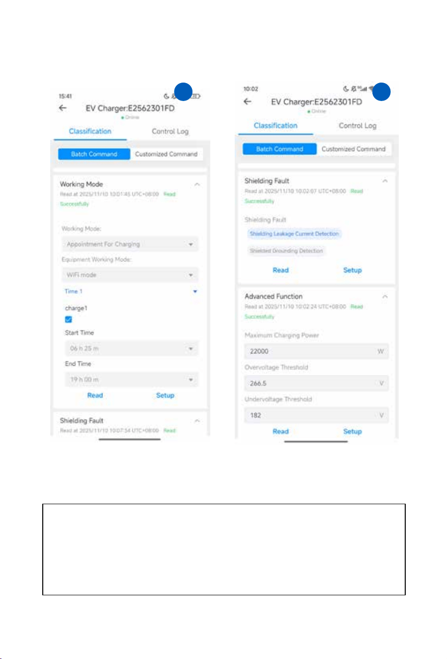
4.Scroll down and you can see more parameter se�ngs
for the EV charger.
Working Mode : This Working Mode feature in the EV charger so�ware lets users manage the device’s
opera�on modes (e.g., scheduled charging), set its working modes (such as WiFi mode), configure specific
charging �me slots, and perform parameter read/setup opera�ons to regulate the EV charger’s opera�onal
behavior.
Shielding Fault:
Func�on for selec�ng fault items (leakage current detec�on or grounding detec�on) to be
shielded for the EV charger.
Advanced Function: Advanced func�on for configuring the EV charger’s maximum charging power,
overvoltage protec�on threshold, and undervoltage protec�on threshold.
� �
- 31 -
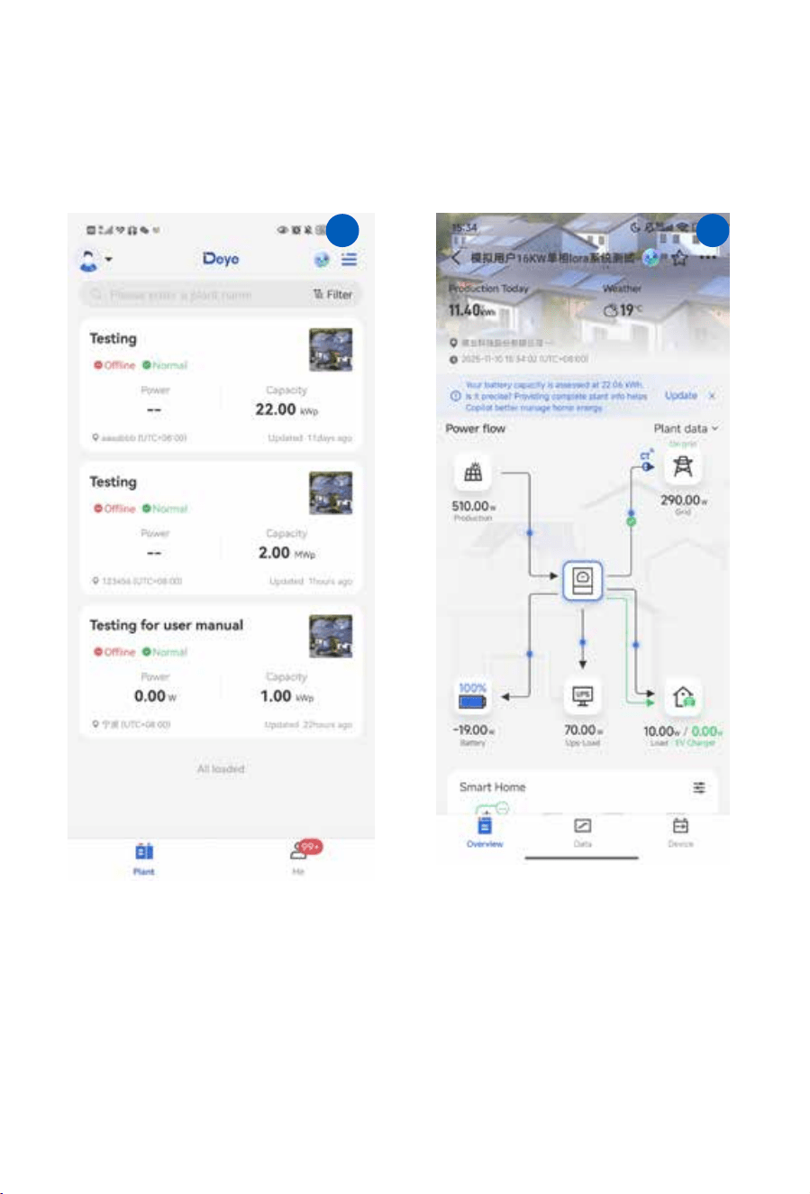
1. Find out the solar plant which the EV charger
is bound in the plant list of the APP.
2. A�er entering the overview page of the solar
plant, you can find the icon of EV charger inside
the power flowing diagram.
� �
�.� With hybrid inverter (LoRa Mode)
- 32 -
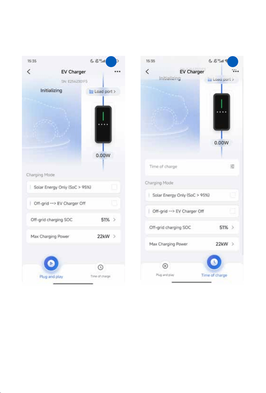
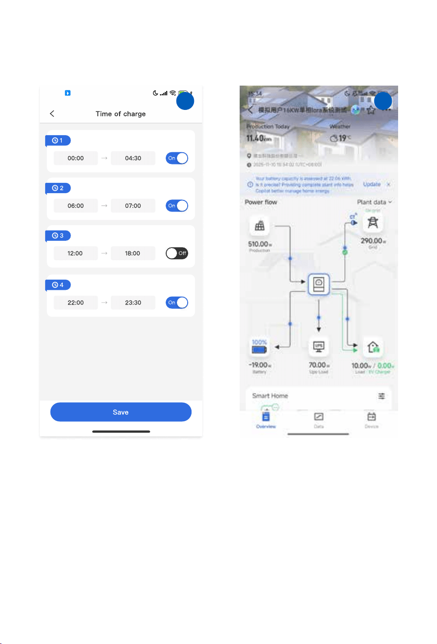
3. Click the icon of EV charger inside the power flowing diagram, the APP will turn to the opera�on
status page of EV charger. And you can also change the se�ngs of EV charger in this page.
All these parameters are the same with the parameters on the LCD of inverter, please check the
parameters explana�on on chapter 7.1
� �
- 33 -
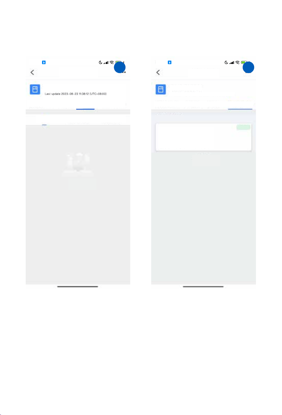
4. Back to the overview page of the solar plant,
and then click the “Devices” item on the down
right corner of overview page to enter the
Device page.
63
16:54
HD
� �
- 34 -
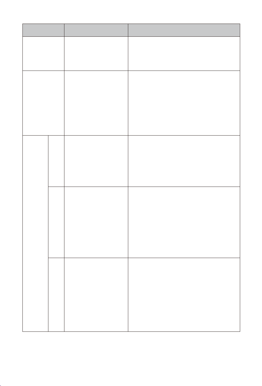
6. Click "Architecture" item on the menu line to
check the Parent Device of this EV charger.
5. Click "Alerts" item on the menu line to enter the
Alerts informa�on page.
EV Charger
SN:E24C0501FF
Device Data
Occurring Recovered
Alerts
All
Architecture
No Alert
63
16:54
HD
All Loaded
63
16:54
HD
EV Charger
SN:E24C0501FF
Last update 2025-01-14 16:53:34 (UTC +08:00)
Device Data
Alerts
Architecture
Lora Master
SN: 2305088702
Updated 2025-01-14 16:54:35
Online
Parent Device
� �
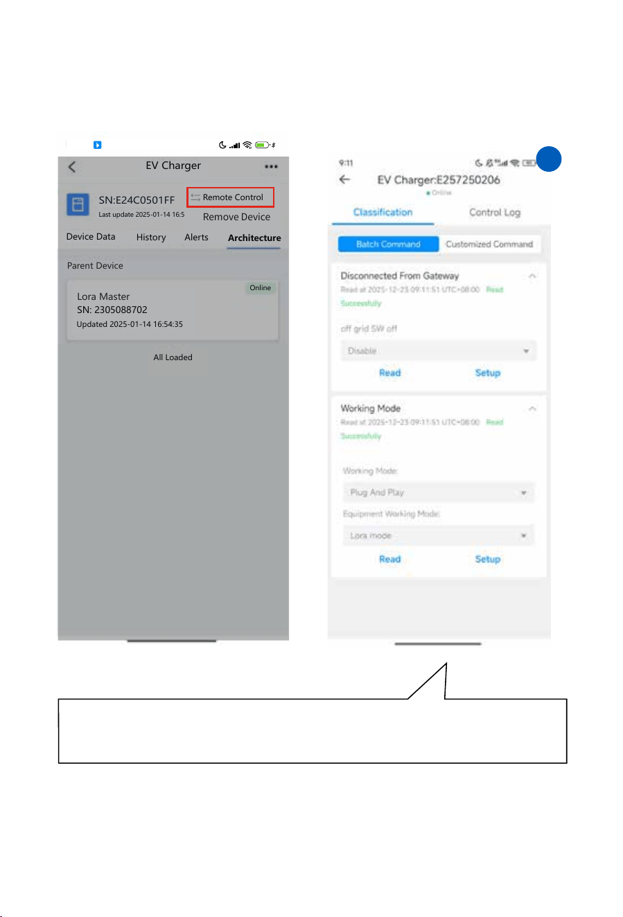
8. There are two subordinate pages for Remote
control, and on the “Classifica�on” page,
you can set the parameters below .
7. Click the "..." icon on the up right corner of the
APP, and then select the "Remote control" .
Gateway Connection: It can read the "Disconnected From Gateway" status, and supports opera�ons like
disabling the off-grid switch (which is currently in "off" state);
Working Mode : It can read the working mode (currently "Plug And Play") and the device communica�on
mode (currently "Lora mode"), and supports configura�on adjustments.
- 35 -
�� ��
All Loaded
SN:E24C0501FF
Last update 2025-01-14 16:53:34 (UTC +08:00)
Device Data
History
Alerts
Architecture
Lora Master
SN: 2305088702
Updated 2025-01-14 16:54:35
Online
Parent Device
Remote Control
63
16:54
HD
EV Charger
�. Troubleshooting
Error Message Solution
Wi-Fi(Green LED)
indicator is OFF
No Wi-Fi connection
No LoRa connection
�. Confirm if the Wi-Fi network of EV charger has been
configured. If not, the network needs to be configured.
�. Confirm if the Wi-Fi signal of the router at the installation
location of EV charger is weak due to distance or
excessive obstacles, if so, please shorten the distance or
increase a signal booster.
�. Confirm whether the hybrid inverter has started up
normally,if not,please wait for the LoRa module of inverter
to start up.
�. Confirm that the SN of EV charger has been added to
the smart device page of the inverter, and that the LoRa
communication connections between other smart devices
and the hybrid inverter are normal.If the EV charger has
been added and the other smart devices can communicate
with inverter normally, then maybe the LoRa module is
fault or damaged.
�. Restart the EV charger,if Lora communication still can
not be normal,please contact Deye support team for
repairing or replacing.
�.Unplug and re-plug and the EV charger connector.
�.Increase the upper limit of charging current.
�.Replace the built-in PCB of EV charger's wall box
In idle state, after the voltage returns to the normal range
���-���.�V, the charger will return to normal. If this fault
occurs during the charging process and the voltage returns
to the normal range, the charger needs to be unpluged and
pluged in again to resume normal operation.If the problem
occurs repeatedly:
�. Check if the input voltage of EV charger is really too high
or the upper limit of input voltage is too low.
�. Properly increase the upper limit of the input voltage
and ensure the input voltage is in reasonable range.
�. Replace the built-in PCB of EV charger's wall box.
The actual charging current of
EV AC charger is greater than the
charging current upper limit
sent by the hybrid inverter, and
last for more than � seconds.
Possible reasons:
�. Hardware issues with electric
vehicle charging circuits.
�. The built-in current sampling
circuit of EV AC charger is faulty.
�.The input voltage exceeds the
upper limit(default value is
���.�V).
�.The voltage sampling circuit is
faulty.
LoRa(Green LED)
indicator is OFF
Alarm(Red
LED)indicator
is blinking
F�
F�
In idle state, after the voltage returns to the normal range
���-���.�V, the charger will return to normal. If this fault
occurs during the charging process and the voltage returns
to the normal range, the charger needs to be unpluged and
pluged in again to resume normal operation. If the problem
occurs repeatedly:
�. Check if the input voltage of EV charger is really too low
or the lower limit of input voltage is too high.
�. Properly decrease the lower limit of the input voltage and
ensure the input voltage is in reasonable range.
�. Replace the built-in PCB of EV charger's wall box.
�.The input voltage is below the
lower limit (default value is ���V).
�.The voltage sampling circuit is
faulty.
F�
- 36 -
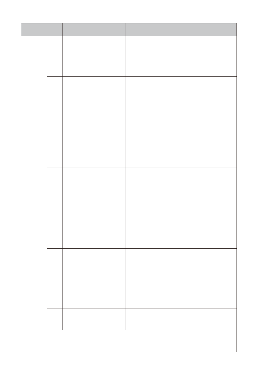
Error Message Solution
�.More than � mA continuous
residual current is detected.
�.The leakage current sampling
CT isn't installed properly
The voltage of CP circuit to
ground is �V, or the voltage is
not equal to �,�,��V
More than �A charging current is
detected when the built-in relays
are not engaged.
Possible reasons:
Some components inside the
wall box are faulty.
One or more built-in relays are faulty.
Possible reasons:
�. The relay is stuck and cannot
be disconnected.
�. The relay cannot be engaged.
The temperature detected by
the sensor exceed ���℃.
Possible reasons:
�.Overtemperature caused by
high frequency of relay opening
and closing.
�.The ventilation and heat
dissipation at the installation
site are poor
Alarm(Red
LED)indicator
is blinking
F�
F�
F�
F�
F�
F�
F��
�. Check if there is any damage to the wiring between the
Wall box and the Charging connector.
�. Restart the EV charger,unplug and plug the charging
connector,than try again.
�. Disassemble the wall box and reinstall the leakage
current sampling CT correctly
If the problem occurs repeatedly, please contact Deye
after-sales support team.
�.Check if the charging connector is in good condition and
free of foreign objects.
�. Restart the EV charger,unplug and plug the charging
connector,and then try again.
If the problem occurs repeatedly, please contact Deye
after-sales support team.
�.Make sure the input voltage of EV charger is stable.
�.Make sure good ventilation conditions at the installation
point of the wall box and that the wall box is not covered
by other objects.
�.Power off the EV charger, and cool down it for a period of
time before restarting
If the problem occurs repeatedly, please contact Deye
after-sales support team.
�.The temperature detected
by the sensor is lower than -��
℃.
�.The temperature sensor
hasn't been assembled
correctly.
The PE wire is not connected
or connected incorrectly
�.Measure the ambient temperature to check whehter it is
lower than -��℃ or not.
�.Disassemble the wall box and reinstall the temperature
sensor.
�.Contact Deye after-sales support team for help.
Restart the EV charger,unplug and plug the charging
connector,and then try again.
If the problem occurs repeatedly, please contact Deye
after-sales support team.
Restart the EV charger,unplug and plug the charging
connector,and then try again.
If the problem occurs repeatedly, please contact Deye
after-sales support team.
�.Check the PE wire connection of EV charger.
In the following scenarios, EV chargers must be directly
grounded:
(�) Connect to single phase hybrid inverter.
(�) Conncect to the grid port of the three phase hybrid
inverter.
(�) No hybrid inverter, connect to other AC power sources
for separate use.
�.When connecting an EV charger to the load port of a
three-phase hybrid inverter and using it during off-grid
operation of the hybrid inverter, it is necessary to enable
the hybrid inverter's "signal island mode".
F��
Lora communication fault.
The chip for lora communica-
tion hasn't welded well
Note: For F� and F�� faults, after recovery, the EV charger must be rest arted to resume normal operation. For other
faults, the fault alarm time cycle is two minutes. If the fault is resolved during this period, the EV charger will return to
normal operation at the end of the two-minute cycle. Otherwise, after two minutes, the EV charger will reset and
check if the fault still exists. If......
�.Disassemble the wall box and check if all the welding
points of Lora communication chip are in good condition.
�.Contact Deye after-sales support team for help.
- 37 -
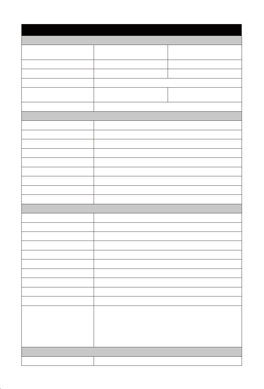
General Data
General Data
Equipment Protection
SUN-EVSE11K01-EU-AC SUN-EVSE22K01-EU-AC
230/400Va.c.(0.8Un to 1.15Un)
230Va.c.(0.8Un to 1.15Un),
230/400Va.c.(0.8Un to 1.15Un)
Model
Product Parameter
Rated Voltage
11kW
7kW (single phase)
22kW (three phase)
Maximum Output Power
Plug And Play/Appointment For ChargingStar�ng Method
3L+N+PE L+N+PE,3L+N+PEConnec�on Mode
16Aa.c. 32Aa.c.Rated Current
50/60HzRated Frequency
YesOver Temperature Protec�on
YesLow Temperature Protec�on
YesOver Voltage Protec�on
YesUnder Voltage Protec�on
YesShort Circuit Protec�on
YesOver Load Protec�on
YesEarth Fault Protec�on
DC 6mALeakage Current Protec�on
TYPE IISurge Protec�on Level
-40 ~ +55℃Opera�ng Temperature Range
5% ~ 95% No condensa�onPermissible Ambient Humidity
≤3000mPermissible Al�tude
<25db
Noise
IP66Ingress Protec�on(IP) Ra�ng
104x264x58Cabinet Size (W*H*D) [mm]
3.7
Weight[kg]
4.2mGun Cable Length
1Number Of Charging Guns
5 Years
Warranty
LoRa/Wi-Fi/BluetoothCommunica�on Mode
EN IEC 61851-1:2019,IEC 61851-1:2017,
EN 300 220-2 V3.1.1:2017,EN 300 328 V2.2.2:2019,
EN IEC 62311:2020,EN 301 489-1 V2.2.3:2019,
EN 301 489-3 V2.3.2:2023,EN 301 489-17 V3.3.1:2024,
EN IEC 61000-6-1:2019,EN IEC 61000-6-3:2021,
EN IEC 61851-21-2:2021
Safety EMC/Standard
��. Technical Data
- 38 -
- 39 -
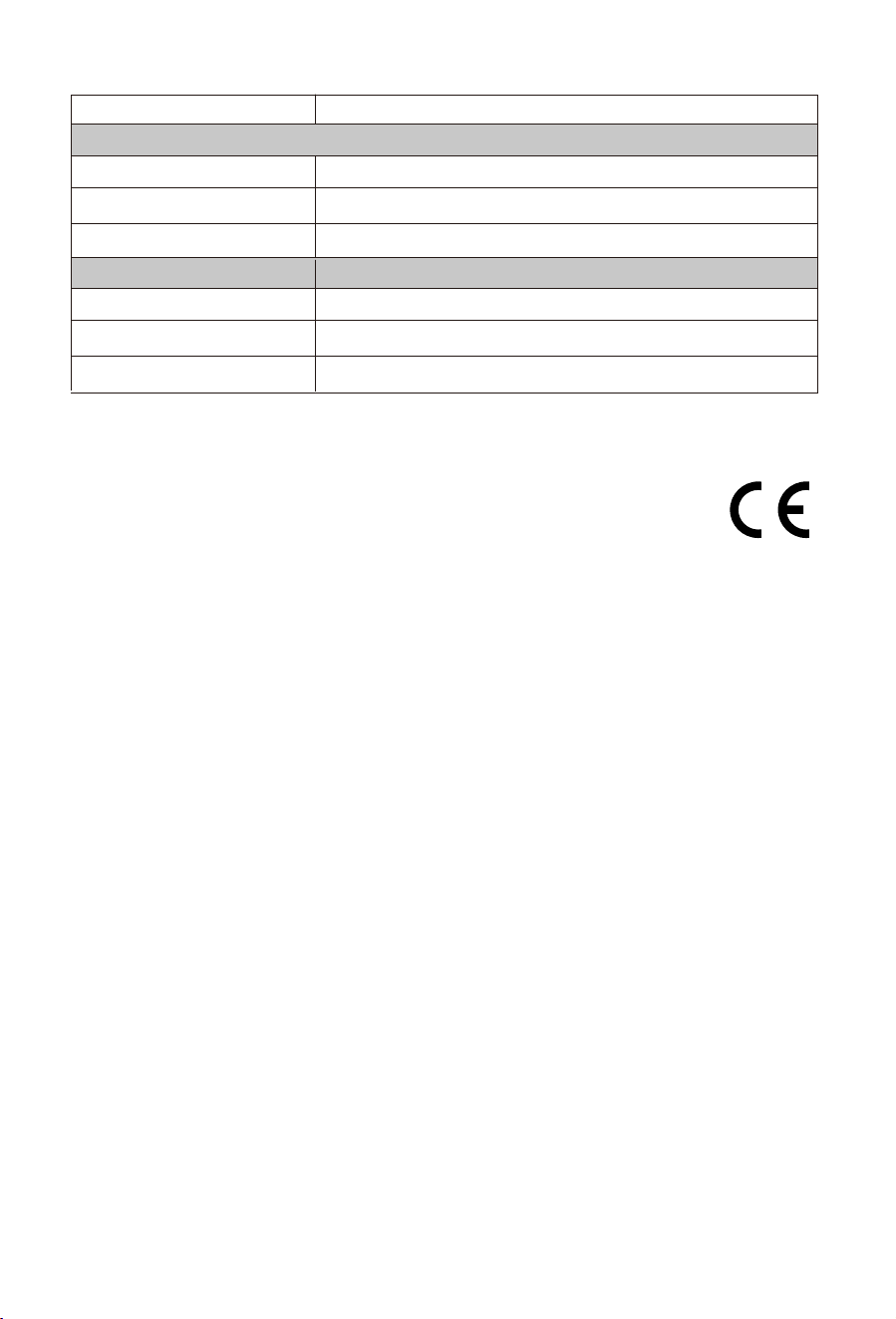
����-��-��
Operating Frequency Band / Maximum output power
2412-2472MHz (TX/RX) / 18.38dBmWi-Fi
Lora communica�on distance
2402-2480MHz (TX/RX) / 8.39dBmBluetooth Low Energy
863-870MHz (TX/RX) / -1.49dBmShort Range Device
Lora Parameter
863MHz-870MHz
Frequency range
Internal Antenna
Antenna
0.56dBi
200m
Antenna gain
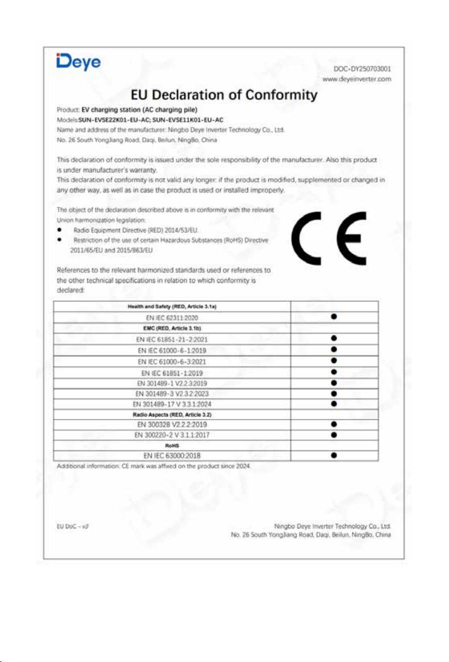
��. EU Declaration of Conformity
Within the scope of the EU directives
· Radio Equipment Directive ����/��/EU (RED)
· Restriction of the use of certain hazardous substances ����/��/EU)(RoHS)
NINGBO DEYE INVERTER TECHNOLOGY CO., LTD. confirms herewith that the products
described in this document are in compliance with the fundamental requirements and other
relevant provisions of the above mentioned directives. The entire EU Declaration of Conformity
and certificate can be found at https://www.deyeinverter.com/download/#smart-load.
- 40 -
- 41 -

Add.: No.26 South YongJiang Road, Daqi, Beilun, NingBo, China.
Tel.: +86 (0) 574 8622 8957
Fax.: +86 (0) 574 8622 8852
E-mail: [email protected]
Web.: www.deyeinverter.com
NINGBO DEYE INVERTER TECHNOLOGY CO., LTD