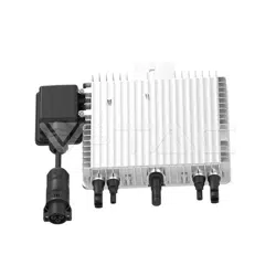
Inverter
PV RSD_12_out
pwd:afc����b
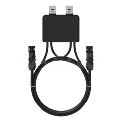
Photovoltaic Smart Optimizer
Operation Manual
About this Manual
This Manual is mainly for the external photovoltaic optimizer independently developed
and produced by Ningbo Deye Inverter Technology Co., Ltd.
Purpose
The purpose of this Manual is to provide readers with the product's detailed information
and installation, operation and maintenance instructions.
Reader orientation
This Manual is suitable for professional technicians and users who install, operate and
maintain the external optimizer.
Use of manual
Read this manual carefully before using this product and keep it in a place where
operation and maintenance personnel can find it easily.
Use of symbol
The following symbols may be used in this Manual, please read them carefully for better
use of this Manual.
"Danger" indicates a situation that has a high potential risk and will result in death or
serious injury if not avoided.
"Warning" indicates a situation that has a moderate potential risk and may result in
death or serious injury if not avoided.
"Caution" indicates a situation that has a low potential risk and may result in moderate
or minor injury if not avoided.
Danger
Warning
Caution
"Attention" indicates a situation that has a potential risk and may result in equipment
failure or property loss if not avoided.
Attention
To ensure the safe installation and operation of optimizer and reduce the risk of electric shock and
equipment damage, the following safety precautions shall be strictly followed during operation and
maintenance.
Check whether the optimizer is abnormal by following the steps below:
(�) To check whether the external optimizer is operated normally, measure the input current of optimizer with
clip-on ammeter. If there is input current, the optimizer is operated normally; if the input current is �, the
optimizer or module is abnormal.
(�) If the input current is �, check whether the module is obviously damaged or seriously blocked. If it is
obviously damaged, replace the module; if it is seriously blocked, remove the block.
(�) If module is normal, check the connected cables for disconnection. After disconnecting the input line of
optimizer (the output line is disconnected first), measure the voltage of positive and negative connectors
of module output line with a multimeter. If the voltage is normal, the line connection is normal; if there is
no voltage, check the line connection further to confirm the open-circuit contact.
(�) If the module and line connection are normal, the replacement of optimizer shall be considered.
Replace the optimizer by following the steps below:
(�) Shut down the inverter and disconnect it from corresponding string;
(�) Disconnect the output line of optimizer;
(�) Disconnect the input line of optimizer;
(�) Remove the original optimizer and install the new one;
(�) Connect the input line;
(�) Connect the output line;
(�) Connect the corresponding string to the later stage inverter;
(�) Restart the inverter;
(�) Test the input current of replaced optimizer with a clip-on ammeter to confirm repair.
The external optimizer is suitable for various types of power stations, distributed and large-scale surface
power stations; new power stations, reconstructive old power stations. In consideration of various mismatch
situations, the installation methods are as follows.
The photovoltaic system has various mismatches, such as shadow shading, inconsistent orientation,
inconsistent aging, stain, glass fragments, ash accumulation, snow accumulation. It can be said that there is no
system without mismatch. The difference lies in the mismatch.
The full installation can solve various series (current) mismatch and recover losses caused by mismatch to the full extent.
�. Safety Instructions
photovoltaic system is that each photovoltaic module is installed with an external optimizer to achieve
module-level MPPT. The input of external optimizer is connected to output of module. The output of
optimizer are connected to each other, which is merged into later stage inverter or combiner box.
Warning
All installation operations must be completed by professional technicians. The professional
technicians must:
1 Undergo specialized training;
2 Read this Manual completely and master the operation-related safety matters;
3 Be familiar with relevant safety specifications of the electrical system.
The optimizer product features are as follows:
�. Product Description
�.� External optimizer
The component-level maximum power point tracking can increase the power generation by �% - ��%.
Monitor the operation of each photovoltaic module in real time. Find problems in time and make
accurate positioning.
Use photovoltaic cable power line carrier communication, without additional communication cable.
�.� Composition of photovoltaic system
Module 1
Module 2
Module 1
Module 2
Photovoltaic
optimizer
Photovoltaic array
Inverter GridCollector
�. Check and Replacement
The following operations must be completed by trained professional technicians to
avoid the risk of electric shock.
Warning
�.� Check
�.� Replacement
�.� One MPPT port with one string
�.�.� Full installation
�.�.� Full installation
�. Instructions to Applicable Scene
�.�.� Installation of mismatched modules
�.� One MPPT port with multiple strings
Risk of installation on mismatched module only:
The mismatch of other modules cannot be solved. When the judgment of system mismatch is not accurate,
for example,some modules are seriously mismatched due to damage while there is no obvious mismatch on
the surface, because the optimizer is not installed, this module will cause great loss to the power generation of
system.
The mismatch is not fixed and will change with time, environment and conditions. If the installation is based
on current mismatch, the mismatch changes after a period of time, the mismatch cannot be solved effectively.
If one MPPT port of the photovoltaic system has multiple strings, there will be series mismatch and parallel
mismatch in the system. The most effective method is full installation.
The full installation in array corresponding to one MPPT port can solve series (current) mismatch and
parallel (voltage) mismatch to recover losses caused by mismatch to the full extent.
If the mismatched modules of system are clear, it can be considered to install only on mismatched modules
or solve series mismatch to save costs.
Instructions for installing mismatched modules:
If module has the clear mismatch, such as shading, low effective illumination caused by orientation
deviation, install on the module with clear mismatch;
If the current value of module with low current in string is different due to the reconstruction and
replacement of the old power station, install on the module with small current values.
When only part of strings in one MPPT port array has clear mismatch and other strings have no obvious
mismatch, it is allowed to install the mismatched strings only. In this way, the series mismatch in this string
can be solved and the losses of power generation can be recovered to a certain extent, but the parallel
mismatch cannot be solved.
When only part of modules in an array has clear mismatch, it is allowed to only install the modules with
clear mismatch. In this way, the mismatch can be solved to a large extent at the lowest cost, so as to recover
losses of power generation.
External
optimizer
Grid
Module
Inverter
Module
Module
Module
External
optimizer
External
optimizer
External
optimizer
External
optimizer
Module
Grid
Module
Inverter
Module
Module Module
External
optimizer
External
optimizer
Module
External
optimizer
Grid
Module
Inverter
Module
Module
Module
Module
External
optimizer
External
optimizer
External
optimizer
External
optimizer
External
optimizer
Module
Module
Module
Module
Module
External
optimizer
External
optimizer
External
optimizer
External
optimizer
External
optimizer
Module
Module
Module
Module
Module
External
optimizer
External
optimizer
External
optimizer
External
optimizer
�.�.� Installation of mismatched string
�.�.� Installation of mismatched module
Grid
Module
Inverter
Module
Module
Module
Module
External
optimizer
Module
Module
Module
Module
Module
External
optimizer
External
optimizer
External
optimizer
External
optimizer
Module
Module
Module
Module
Module
Grid
Inverter
Module
Module
Module
Module
Module
External
optimizer
External
optimizer
Module
Module
Module
Module
Module
Module
Module
Module
Module
Module
Model SUN-XL��-B
��V
��-��V
��A
���WMax. Input/output power(DC)
Max. Input/output voltage(DC)
MPPT voltage range(DC)
Max. Input/output current(DC)
Project Parameter
Peak conversion efficiency ��.�%
Installation specifications
dimensions(mm)
���*���*��mm
Ingress Protection (IP) Rating IP��
Product certification CE
Weight (g)
Cable
Connector MC� Or Compatible with MC�
���g
�.�mm² input ��cm output ���cm customizable
-��℃ to +��℃
Operating temperature
Product Specification
EU Declaration of Conformity
within the scope of the EU directives
· Radio Equipment Directive ����/��/EU (RED)
· Restriction of the use of certain hazardous substances ����/��/EU)(RoHS)
NINGBO DEYE INVERTER TECHNOLOGY CO.,LTD. confirms herewith that the products
described in this document are in compliance with the fundamental requirements and other
relevant provisions of the above mentioned directives. The entire EU Declaration of Conformity
and certificate can be found at https://www.deyeinverter.com/download/#pv-optimizer.
�.� Installation of optimizer concentrator
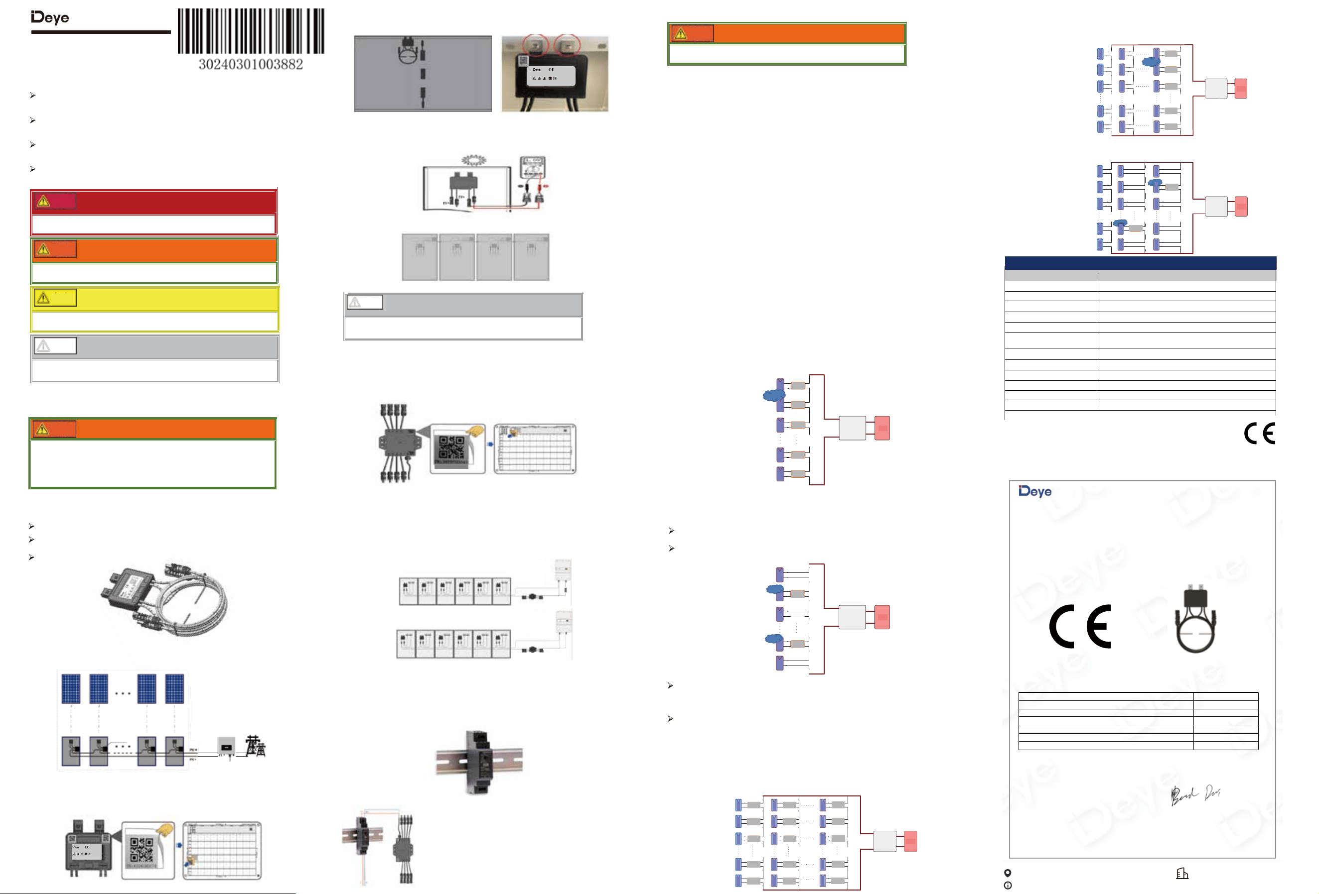
Step �. Fixed optimizer, insert the two metal clips at the top of the optimizer into the metal slots on the side
of the component frame, as close as possible to the positive and negative terminals of the component power
supply, as shown in figures b and c.
Step �. Connection of optimizer
(�) Connect the optimizer input IN+and IN - to the PV+and PV - of the photovoltaic module junction box.
(�) Connect the positive probe of the multimeter to the positive output of the optimizer and the negative probe
to the negative output. Check the voltage output of the optimizer (�.�V-�.�V), as shown in Figure d.
The optimizer concentrator supports up to � strings, and a single string can support up to �� components
(depending on the capacity of the inverter). For example, if the on-site inverter supports two string inputs, the
optimizer concentrator only needs two strings connected to the PV inputs of the string and the inverter. The
communication distance between the optimizer concentrator and the strings should not exceed ���m.
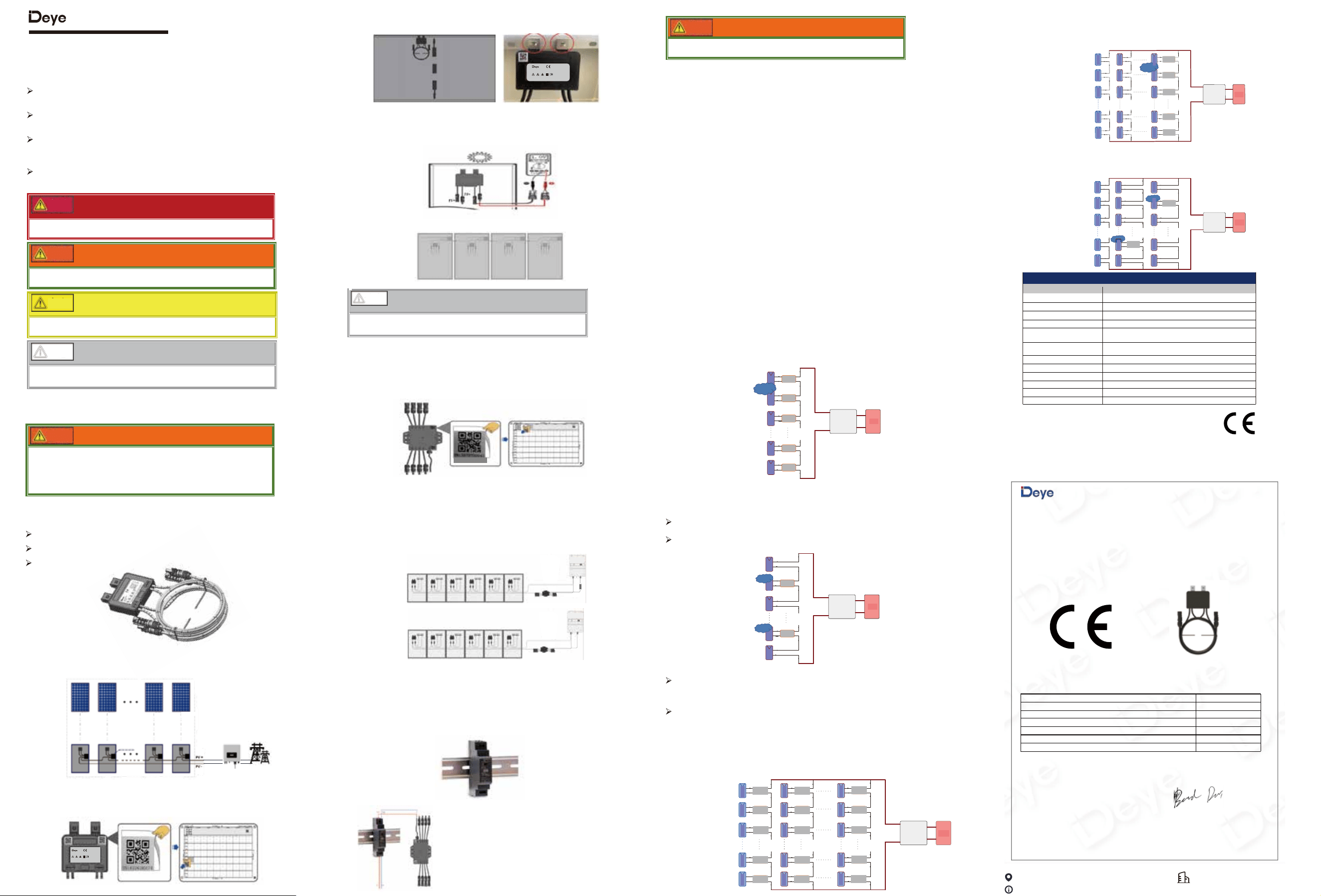
�. Tear off the QR code and remove the QR code label at the indicated position as shown in Figure f, and paste
it in the designated area of the physical layout template.
After confirming the correct connection, turn on the power and the
working indicator light will turn on, indicating that the optimizer
concentrator is working properly and system parameter configuration
can be performed. Please refer to the system software operation
instructions for details.
(�) After installing a single optimizer, concatenate the outputs of the optimizer in sequence to form a string, as
shown in Figure e.
Before connecting the string to the inverter, use a multimeter to measure the voltage
at both ends of the string in the DC voltage range to see if it is normal N * (0.9V-1.1V).
Attention
b. Diagram of the location of the optimizer component
e. Optimizer string connection diagram
c. Optimizer fixed diagram
�.� Optimizer installation
Step �. Tear off the QR code, and after determining the installation position of the optimizer, as shown in
Figure A, remove the QR code label at the indicated position and paste it onto the physical layout template.
�. System Installation Instructions
a. Tear off and paste the QR code label diagram
�.� Installation of rail type power supply
�. Fixed power supply
The rail power supply (is included as standard) must be installed in a distribution cabinet or waterproof box
and fixed as shown in the diagram.
f. Schematic diagram of optimizer concentrator QR code tearing and pasting
i. Schematic diagram of fixed rail power supply
Photovoltaic Smart Optimizer
Model: SUN-XL��-B
Max. Input/output power(DC): ���W
��AMax. Input/output current(DC):
99.5%Peak conversion efficiency:
-40℃ to +��℃Operating temperature:
IP��Ingress Protection (IP) Rating:
��VMax. Input/output voltage(DC):
��-��VMPPT voltage range(DC):
Add.: No.�� South YongJiang Road, Daqi, Beilun, NingBo, ChinaNINGBO DEYE INVERTER TECHNOLOGY CO.,LTD.
CAUTION-Risk of Electric Shock Do Not Remove Cover. No User Ser
viceable Parts Inside. Refer Servicing to Qualified Service Personnel.
High Voltage Warning Danger Caution Hot Double Insulation Instruction
Photovoltaic Smart Optimizer
Model: SUN-XL��-B
Max. Input/output power(DC): ���W
��AMax. Input/output current(DC):
99.5%Peak conversion efficiency:
-40℃ to +��℃Operating temperature:
IP��Ingress Protection (IP) Rating:
��VMax. Input/output voltage(DC):
��-��VMPPT voltage range(DC):
Add.: No.�� South YongJiang Road, Daqi, Beilun, NingBo, ChinaNINGBO DEYE INVERTER TECHNOLOGY CO.,LTD.
CAUTION-Risk of Electric Shock Do Not Remove Cover. No User Serviceable Parts Inside. Refer Servicing to Qualified Service Personnel.
High Voltage Warning Danger Caution Hot Double Insulation Instruction
�. Power connection
+ IN -
+ ON -
d. Optimizer output detection
Inverter
Inverter
PV LOAD
DC
AC
�. Optimizer concentrator fixed
The optimizer concentrator is equipped with built-in WIFI and powered by an adapter. It is necessary to
consider the coverage of WIFI signals and the connection of AC power to the adapter.
�. Optimizer Concentrator Connection
Connect the PV+or PV - in the connected string sequentially through the string end of the optimizer concentra-
tor and then connect it to the inverter, as shown in Figure g.
If the machine has a rapid shutdown function, you can connect the inverter directly without using a power
module,as shown in Figure h. If there is no shutdown function, follow the previous operation.
g. Schematic diagram of optimizer concentrator connection
h. Use the RSD port of inverter to supply the concentertor
Note:
�.To minimize electromagnetic interference, it is recommended to shorten the length of the cables from the
optimizer to the inverter and optimizer concentrator as much as possible.
�.To ensure the commuinication stable, it's recommended to dividually layout the PV cable and AC cable of
this solar system, make sure the distance between them is more than ��cm.
2506090001-R1
www.deyeinverter.com
EU DoC
– v3
Ningbo Deye Inverter Technology Co., Ltd.
No. 26 South YongJiang Road, Daq i, Beilun, NingBo, China
EU Declaration of Conformity
Product:
Photovoltaic Smart Optimize
Models: SUN-XL02-A;SUN-XL02-B;SUN-XL02-C
Name and address of the manufacturer: Ningbo Deye Inverter Technology Co., Ltd.
No. 26 South YongJiang Road, Daq i, Beilun, NingBo, China
Name and address of authorized EU/EEA importer: Tuta Blu d.o.o. HR-10 000 Zagreb, Ulica grada Vukovara 226G
This declaration of conformity is issued under the sole responsibility of the manufacturer. Also this product
is
under manufacturer’s warranty.
This declaration of conformity is not valid any longer: if the product is modified, supplemented or changed in
any other way, as well as in case the product is used or installed improperly.
Object of the declaration:
Photovoltaic Smart Optimize
Model reference:
SUN-XL02-A;SUN-XL02-B;SUN-XL02-C
The object of the declaration described above is in conformity with the relevant Union harmonization legislation:
The Low Voltage Directive (LVD) 2014/35/EU;the Electromagnetic Compatibility (EMC) Directive 2014/30/EU;the
restriction of the use of certain hazardous substances (RoHS) Directive 2011/65/EU.
References to the relevant harmonized standards used or references to the other technical specifications in
relation to which conformity is declared:
Additional information: CE mark was affixed on the product since 2023.
SGS tes ted the sample in accordance with the standards and issued the certificate, certificate
number:GZES2506010749PV;GZES2506010749PV
Please note that the test was performed on the sample, as each device has a separa te serial number. Please refer to the
models name.The manufacturer's declaration applies to all devices serial number.
LVD:
EN 62109-1:2010
🔴
EMC:
EN IEC 61000-6-2:2019
🔴
EN IEC 61000-6-3:2021
🔴
RoHS:
EN IEC 63000:2018
🔴
Nom et Titre / Name and Title:
Au nom de / On behalf of:
Date / Date (yyyy-mm-dd):
A / Place:
Bard Dai
Senior Standard and Certification Engineer
Ningbo Deye Inverter Technology Co., Ltd.
2025-06-09
Ningbo, China
Ningbo Deye Inverter Technology Co., Ltd.
Contact Information
No.�� South YongJiang Road, Daqi, Beilun, NingBo, China
�.�.�
pwd:afc����b
Abb. A: Abreißen und Einkleben des QR-Code-Etiketts
Modul 1
Modul 2
Modul 1
Modul 2
Photovoltaik
- Optimierer
Photovoltaik-Array
Wechselrichter NetzKollektor
Smart PV-Optimierer
Benutzerhandbuch
Über dieses Handbuch
Dieses Handbuch bezieht sich hauptsächlich auf den externen Photovoltaik-Optimierer,
der von Ningbo Deye Inverter Technology Co., Ltd. entwickelt und hergestellt wird.
Zweck
Zweck dieses Handbuchs ist es, den Lesern detaillierte Informationen über das Produkt
sowie Anweisungen zur Installation, Benutzung und Wartung zu geben.
Leserorientierung
Dieses Handbuch ist für professionelle Techniker und Benutzer geeignet, die den
externen Optimierer installieren, benutzen und warten.
Verwendung von Symbolen
Lesen Sie dieses Handbuch sorgfältig durch, bevor Sie das Produkt benutzen, und
bewahren Sie es an einem Ort auf, an dem das Bedienungs- und Wartungspersonal es
leicht finden kann.
Verwendung von Symbolen
Die folgenden Symbole können in diesem Handbuch verwendet werden. Bitte lesen Sie
sie sorgfältig durch, um dieses Handbuch besser nutzen zu können.
"Gefahr" weist auf eine Situation hin, die ein hohes Risiko birgt und zum Tod oder zu
schweren Verletzungen führt, wenn sie nicht vermieden wird.
Gefahr
"Warnung" weist auf eine Situation hin, die ein mittleres Risikopotenzial birgt und zum
Tod oder zu schweren Verletzungen führen kann, wenn sie nicht vermieden wird.
Warnung
"Vorsicht" weist auf eine Situation hin, die ein geringes potenzielles Risiko birgt und
mittelschweren oder leichten Verletzungen führen kann, wenn sie nicht vermieden wird.
Vorsicht
"Achtung" weist auf eine Situation hin, die ein potenzielles Risiko birgt und zum Ausfall
von Geräten oder zum Verlust von Eigentum führen kann, wenn sie nicht vermieden wird.
Achtung
Um die sichere Installation und Benutzung des Optimierers zu gewährleisten und die Gefahr
von Stromschlägen und Geräteschäden zu verringern, müssen die folgenden Sicherhe-
itsvorkehrungen während der Benutzung und der Wartung strikt eingehalten werden.
Prüfen Sie anhand der folgenden Schritte, ob der Optimierer normal arbeitet:
(�) Um zu prüfen, ob der externe Optimierer normal arbeitet, messen Sie den Eingangsstrom des
Optimierers mit einer Strom-Messzange. Wenn der Eingangsstrom vorhanden ist, wird der Optimierer
normal arbeiten. Wenn der Eingangsstrom � ist, ist der Optimierer oder das Modul nicht in Ordnung.
Tauschen Sie den Optimierer aus, indem Sie die folgenden Schritte ausführen:
(�)Schalten Sie den Wechselrichter aus und trennen Sie ihn vom entsprechenden String.
(�)Trennen Sie die Ausgangskabel des Optimierers ab.
(�)Trennen Sie die Eingangskabel des Optimierers ab.
(�)Entfernen Sie den ursprünglichen Optimierer und installieren Sie einen neuen.
(�)Schließen Sie die Eingangskabel des Optimierers an.
(�)Schließen Sie die Ausgangskabel des Optimierers an.
(�)Schließen Sie den entsprechenden String an den nachgeschalteten Wechselrichter an.
(�)Starten Sie den Wechselrichter erneut.
(�)Prüfen Sie den Eingangsstrom des ausgetauschten Optimierers mit einer Strom-Messzange, um die Reparatur mit
Erfolg zu bestätigen.
Der externe Optimierer eignet sich für verschiedene Arten von Solarkraftwerken, dezentralen und großflächigen
Solarkraftwerken, neuen und rekonstruierten alten Solarkraftwerken. Angesichts der verschiedenen möglichen
Fehlanpassungen sind die Installationsmethoden wie folgt aufgeführt.
Das Photovoltaik-System weist oft verschiedene Fehlanpassungen auf, z. B. Schattenwurf, uneinheitliche Ausrichtung,
uneinheitliche Alterung, Flecken, Glasscherben, Asche- und Schneeansammlungen. Man kann sagen, dass es kein
System ohne Fehlanpassungen gibt. Der Unterschied liegt in der Fehlanpassung.
Eine vollständige Installation kann ein breites Spektrum von Serien-(Strom-)Fehlanpassungen lösen und die durch
Fehlanpassungen verursachten Verluste vollständig zurückgewinnen.
�. Sicherheitshinweise
Das Photovoltaik-System besteht darin, dass jedes Photovoltaik-Modul mit einem externen Optimierer
installiert wird, um MPPT auf Modulebene zu erreichen. Der Eingang des externen Optimierers ist mit dem
Ausgang des Moduls verbunden. Die Ausgänge der Optimierer sind miteinander verbunden und werden
später in einem Wechselrichter oder Kombikasten zusammengeführt.
Warnung
Alle Installationsarbeiten müssen von professionellen Technikern durchgeführt werden.
Die professionellen Techniker müssen:
(1) eine spezielle Ausbildung absolviert haben;
(2) dieses Handbuch vollständig durchlesen und sich mit den sicherheitsrelevanten
Aspekten der Nutzung vertraut machen;
(3) mit den relevanten Sicherheitsspezifikationen der elektrischen Anlage vertraut sein.
Die Produktmerkmale des Optimierers sind wie folgt:
�. Produktbeschreibung
�.� Externer Optimierer
Das Maximum Power Point Tracking (MPPT) auf Komponentenebene kann die Stromerzeugung
um �% - ��% steigern.
�.� Aufbau des Photovoltaik-Systems
�. Prüfen und Austauschen
Die folgenden Arbeiten müssen von geschultem Fachpersonal durchgeführt werden,
um die Gefahr eines Stromschlags zu vermeiden.
Warnung
�.� Prüfen
�.� Austauschen
�. Anweisungen für die anwendbaren Szenarien
�.� Ein MPPT-Anschluss mit einem String
�.�.� Vollständige Installation
�.�.� Vollständige Installation
Produktspezifikation
�.�.� Installation auf fehlangepassten Modulen
�.� Ein MPPT-Anschluss mit mehreren Strings
Risiko der Installation nur auf fehlangepasstem Modul:
Die Fehlanpassung anderer Module kann nicht behoben werden. Wenn die Beurteilung der Systemfehlanpassung
nicht genau ist, z.B. einige Module sind ernsthaft fehlangepasst aufgrund von Schäden, während es keine
offensichtliche Fehlanpassung auf der Oberfläche gibt. Weil der Optimierer nicht darauf installiert ist, wird dieses
Modul großen Verlust für die Stromerzeugung des Systems verursachen.
Die Fehlanpassung ist nicht fix und ändert sich mit der Zeit, der Umgebung und den Bedingungen. Wenn die
Installation auf der aktuellen Fehlanpassung basiert, ändert sich die Fehlanpassung nach einer gewissen Zeit,
die Fehlanpassung kann damit nicht effektiv behoben werden.
Wenn ein MPPT-Anschluss des Photovoltaik-Systems mehrere Strings hat, kommt es zu einer Reihen- und Parallelfehlan-
passung im System. Die effektivste Methode ist die vollständige Installation.
Die vollständige Installation in einem Array, das einem MPPT-Anschluss entspricht, kann eine serielle (Strom-) Fehlanpassung
und eine parallele (Spannungs-) Fehlanpassung beheben, um die durch die Fehlanpassung verursachten Verluste in vollem
Umfang zurück zu gewinnen.
Wenn die fehlangepassten Module des Systems eindeutig sind, kann in Betracht gezogen werden, nur diese Module
damit zu installieren oder die Fehlanpassung in der Reihe zu beheben, um Kosten zu sparen.
Anweisungen für die Installation auf fehlangepassten Modulen:
Wenn das Modul eine eindeutige Fehlanpassung aufweist, wie z. B. , geringe effektive Belichtung aufgrund von
Ausrichtungsabweichungen und Abschattung, installieren Sie ihn auf dem Modul mit eindeutiger Fehlanpassung.
Wenn der Stromwert des Moduls mit niedrigem Strom im String aufgrund der Rekonstruktion und des Austauschs des
alten Solarkraftwerks unterschiedlich ist, installieren Sie ihn auf dem Modul mit kleinen Stromwerten.
Wenn nur ein Teil des Strings in einem MPPT-Anschluss-Array eine eindeutige Fehlanpassung aufweist und die
anderen Strings keine offensichtliche Fehlanpassung aufweisen, können nur die fehlangepassten Strings damit
installiert werden. Auf diese Weise kann die Reihenfehlanpassung in diesem String behoben und die Verluste bei
der Stromerzeugung bis zu einem gewissen Grad ausgeglichen werden, aber die Parallelfehlanpassung kann nicht
behoben werden.
Wenn nur ein Teil der Module in einem Array eine eindeutige Fehlanpassung aufweist, dürfen nur die Module mit
eindeutiger Fehlanpassung damit installiert werden. Auf diese Weise kann die Fehlanpassung mit geringsten
Kosten weitgehend behoben werden, so dass die Verluste bei der Stromerzeugung ausgeglichen werden.
Externer
Optimierer
Netz
Modul
Wechselrichter
Modul
Module
Modul
Externer
Optimierer
Externer
Optimierer
Externer
Optimierer
Externer
Optimierer
Modul
Netz
Modul
Wechselrichter
Modul
Modul Modul
Externer
Optimiere
Externer
Optimiere
Modul
Externer
Optimierer
Netz
Modul
Wechselrichter
Modul
Modul
Modul
Modul
Externer
Optimierer
Externer
Optimierer
Externer
Optimierer
Externer
Optimierer
Externer
Optimierer
Modul
Modul
Modul
Modul
Modul
Externer
Optimierer
Externer
Optimierer
Externer
Optimierer
Externer
Optimierer
Externer
Optimierer
Modul
Modul
Modul
Modul
Modul
Externer
Optimierer
Externer
Optimierer
Externer
Optimierer
Externer
Optimierer
�.�.� Installation an fehlangepasstem String
�.�.� Installation auf fehlangepasstem Modul
Netz
Modul
Wechselrichter
Modul
Modul
Modul
Modul
Externer
Optimiere
Modul
Modul
Modul
Modul
Modul
Externer
Optimiere
Externer
Optimiere
Externer
Optimiere
Externer
Optimiere
Modul
Modul
Modul
Modul
Modul
Netz
Wechselrichter
Modul
Modul
Modul
Modul
Modul
Externer
Optimiere
Externer
Optimiere
Modul
Modul
Modul
Modul
Modul
Modul
Modul
Modul
Modul
Modul
Überwachung des Betriebs der einzelnen Photovoltaik-Module in Echtzeit. Probleme rechtzeitig erkennen
und eine genaue Positionierung vornehmen.
Powerline-Trägerkommunikation über Photovoltaikkabel, ohne zusätzliche Kommunikationskabel.
(�) Wenn der Eingangsstrom � ist, prüfen Sie, ob das Modul offensichtlich beschädigt oder stark blockiert
ist. Wenn es offensichtlich beschädigt ist, tauschen Sie das Modul aus. Wenn es ernsthaft blockiert ist,
entfernen Sie den Blockierer.
(�) Wenn das Modul normal ist, prüfen Sie die angeschlossenen Kabel auf Unterbrechungen. Nachdem
Sie die Eingangskabel des Optimierers abgeklemmt haben (die Ausgangskabel werden zuerst abgeklemmt),
messen Sie die Spannung an den positiven und negativen Anschlüssen der Ausgangskabel des Moduls mit
einem Multimeter. Wenn die Spannung normal ist, sind die Kabel normal. Wenn keine Spannung vorhanden
ist, prüfen Sie die Kabel weiter, um den offenen Stromkreis-Kontakt zu finden.
(�) Wenn das Modul und die Kabelverbindungen normal sind, sollte der Optimierer ausgetauscht werden.
Modell SUN-XL��-B
��V
��-��V
��A
���W
Max. Eingang-/Ausgangsleistung(DC)
Max. Eingang-/Ausgangsspannung(DC)
MPPT-Spannungsbereich(DC)
Max. Eingang-/Ausgangsstrom(DC)
Projekt Parameter
Wirkungsgrad der
Spitzenumwandlung
��.�%
Einbauspezifikationen
Abmessungen (mm)
���*���*��mm
Schutzartg IP��
Produktzertifizierung CE
Gewicht (g)
Kabel
Anschluss MC� oder MC�-kompatibel
���g
�,�mm², Eingang ��cm, Ausgang ���cm, anpassbar
-��℃ to +��℃
Betriebstemperaturbereich
Ningbo Deye Inverter Technology Co., Ltd.
Kontaktinformationen
No.�� South YongJiang Road, Daqi, Beilun, NingBo, China
EU-Konformitätserklärung
Im Geltungsbereich der EU-Richtlinie
· Funkanlagenrichtlinie ����/��/EU (RED)
· Beschränkung der Verwendung bestimmter gefährlicher Stoffe ����/��/EU (RoHS)
Ningbo Deye Inverter Technology Co., Ltd. bestätigt hiermit, dass die in diesem Dokument
beschriebenen Produkte entsprechen den grundlegenden Anforderungen und anderer
einschlägiger Bestimmungen der oben genannten Richtlinien .
Die vollständige EU-Konformitätserklärung finden und Zertifikat Sie auf
https://www.deyeinverter.com/download/#pv-optimizer.
�.�.�
�.� Installation des Optimierers
Schritt �. Reißen Sie den QR-Code ab, und nachdem Sie die Einbauposition des Optimierers bestimmt
haben, wie in Abb. A gezeigt, entfernen Sie das QR-Code-Etikett an der angegebenen Position und kleben Sie
es auf die physische Layoutvorlage.
�. Anleitung zur Systeminstallation
�.� Installation des Optimierer-Konzentrators
Schritt �. Befestigen Sie den Optimierer, indem Sie die beiden Metallklammern an der Oberseite des
Optimierers in die Metallschlitze an der Seite des Bauteilrahmens einführen, und zwar so nah wie möglich an
den Plus- und Minuspolen der Bauteil-Stromversorgung, wie in den Abb. B und C gezeigt.
Schritt �. Anschließen des Optimierers
(�) Verbinden Sie die Eingänge IN+ und IN- des Optimierers mit den Anschlüssen PV+ und PV- der
Anschlussdose des PV-Moduls.
(�) Schließen Sie die positive Meßspitze des Multimeters an den positiven Ausgang des Optimierers und die
negative Meßspitze an den negativen Ausgang an. Prüfen Sie die Ausgangsspannung des Optimierers
(�,�V-�,�V), wie in Abb. D gezeigt.
Nachdem Sie den Anschluss korrekt festgestellt haben, schalten Sie
den Strom ein. Die Betriebsanzeige leuchtet auf und zeigt damit an,
dass der Optimierer- Konzentrator einwandfrei funktioniert und die
Konfiguration der Systemparameter durchgeführt werden kann.
Einzelheiten siehe die Bedienungsanleitung der Systemsoftware.
(�) Nach der Installation der einzelnen Optimierer verketten Sie die Ausgänge der Optimierer nacheinander zu
einem Strang, wie in Abb. E gezeigt.
Bevor Sie den Strang an den Wechselrichter anschließen, messen Sie mit einem
Multimeter die Spannung an beiden Enden des Strangs im Gleichspannungsbereich,
um festzustellen, ob sie normal N * (0,9V-1,1V) ist.
Achtung
Abb. B: Position der Optimierungskomponente
Abb. E: Anschlussplan des Optimierer-Strangs
Abb. C: Befestigung des Optimierers
Abb. D: Erkennung des Optimiererausgangs
Abb. F: Abreißen und Einkleben des QR-Code-Etiketts des Optimierer-Konzentrators
Der Optimierer-Konzentrator unterstützt bis zu � Stränge, und ein einzelner Strang unterstützt bis zu ��
Komponenten (abhängig von der Kapazität des Wechselrichters). Z.B: Wenn der Wechselrichter vor Ort zwei
Strang-Eingänge unterstützt, braucht der Optimierer-Konzentrator nur zwei Stränge, die mit den PV-Eingän-
gen des Strangs und des Wechselrichters verbunden sind. Die Kommunikationsreichweite zwischen dem
Optimierer-Konzentrator und den Strängen sollte ��� m nicht überschreiten.
�. Reißen Sie den QR-Code ab, entfernen Sie das QR-Code-Etikett an der angegebenen Position (siehe Abb. F)
und kleben Sie es an der vorgesehenen Stelle der physischen Layoutvorlage ein.
Photovoltaic Smart Optimizer
Model: SUN-XL��-B
Max. Input/output power(DC): ���W
��AMax. Input/output current(DC):
99.5%Peak conversion efficiency:
-40
℃ to +��℃
Operating temperature:
IP��Ingress Protection (IP) Rating:
��VMax. Input/output voltage(DC):
��-��VMPPT voltage range(DC):
Add.: No.�� South YongJiang Road, Daqi, Beilun, NingBo, ChinaNINGBO DEYE INVERTER TECHNOLOGY CO.,LTD.
CAUTION-Risk of Electric Shock Do Not Remove Cover. No User Serviceable Parts Inside. Refer Servicing to Qualified Service Pers
onnel.
High Voltage Warning Danger Caution Hot Double Insulation Instruction
Photovoltaic Smart Optimizer
Model: SUN-XL��-B
Max. Input/output power(DC): ���W
��AMax. Input/output current(DC):
99.5%Peak conversion efficiency:
-40℃ to +��℃Operating temperature:
IP��Ingress Protection (IP) Rating:
��VMax. Input/output voltage(DC):
��-��VMPPT voltage range(DC):
Add.: No.�� South YongJiang Road, Daqi, Beilun, NingBo, ChinaNINGBO DEYE INVERTER TECHNOLOGY CO.,LTD.
CAUTION-Risk of Electric Shock Do Not Remove Cover. No User Serviceable Parts Inside. Refer Servicing to Qualified Service Personnel.
High Voltage Warning Danger Caution Hot Double Insulation Instruction
Inverter
PV LOAD
DC
AC
Wechselrichter
Wechselrichter
PV RSD_12_out
Abb. G: Anschließen des Optimierer-Konzentrators
�. Anschließen der Stromversorgung
Abb. I: Befestigung der Stromversorgung an der Schiene
�.� Installation der Stromversorgung auf der Schiene
�. Befestigen der Stromversorgung
Die Schienenstromversorgung (im Lieferumfang enthalten) muss in einem Verteilerkasten oder einer
wasserdichten Box installiert und wie in der Abbildung gezeigt befestigt werden.
�. Befestigen des Optimierer-Konzentrators
Der Optimierer-Konzentrator ist mit eingebautem WIFI ausgestattet und wird über einen Adapter mit Strom
versorgt. Es müssen die Reichweite der WIFI-Signale und der Anschluss der AC-Stromversorgung an den
Adapter berücksichtigt werden.
�. Anschließen des Optimierer-Konzentrators
Verbinden Sie die PV+ oder PV- im angeschlossenen Strang nacheinander mit dem Strang-Ende des
Optimierer-Konzentrators und schließen Sie ihn dann an den Wechselrichter an, wie in Abb. G gezeigt.
Wenn die Maschine über eine Schnellabschaltfunktion verfügt, können Sie den Inverter direkt anschließen,
ohne ein Stromversorgungsmodul zu verwenden (siehe Abbildung h). Wenn keine Abschaltfunktion
vorhanden ist, gehen Sie wie oben beschrieben vor.
Abb. H: Verwenden Sie den RSD-Anschluss des Wechselrichters zur
Stromversorgung des Konzentrators.
Anmerkung:
�. Zur Minimierung elektromagnetischer Störungen wird empfohlen, die Kabellänge zwischen dem
Optimierer, dem Wechselrichter und dem Konzentrator so kurz wie möglich zu halten.
�. Zur Sicherstellung einer stabilen Kommunikation wird empfohlen, das PV-Kabel und das AC-Kabel dieses
Solarsystems getrennt zu verlegen und den Abstand zwischen ihnen auf mindestens �� cm zu halten.
2506090001-R1
www.deyeinverter.com
EU DoC
– v3
Ningbo Deye Inverter Technology Co., Ltd.
No. 26 South YongJiang Road, Daq i, Beilun, NingBo, China
EU Declaration of Conformity
Product:
Photovoltaic Smart Optimize
Models: SUN-XL02-A;SUN-XL02-B;SUN-XL02-C
Name and address of the manufacturer: Ningbo Deye Inverter Technology Co., Ltd.
No. 26 South YongJiang Road, Daq i, Beilun, NingBo, China
Name and address of authorized EU/EEA importer: Tuta Blu d.o.o. HR-10 000 Zagreb, Ulica grada Vukovara 226G
This declaration of conformity is issued under the sole responsibility of the manufacturer. Also this product
is
under manufacturer’s warranty.
This declaration of conformity is not valid any longer: if the product is modified, supplemented or changed in
any other way, as well as in case the product is used or installed improperly.
Object of the declaration:
Photovoltaic Smart Optimize
Model reference:
SUN-XL02-A;SUN-XL02-B;SUN-XL02-C
The object of the declaration described above is in conformity with the relevant Union harmonization legislation:
The Low Voltage Directive (LVD) 2014/35/EU;the Electromagnetic Compatibility (EMC) Directive 2014/30/EU;the
restriction of the use of certain hazardous substances (RoHS) Directive 2011/65/EU.
References to the relevant harmonized standards used or references to the other technical specifications in
relation to which conformity is declared:
Additional information: CE mark was affixed on the product since 2023.
SGS tes ted the sample in accordance with the standards and issued the certificate, certificate
number:GZES2506010749PV;GZES2506010749PV
Please note that the test was performed on the sample, as each device has a separate s erial number. Please refer to the
models name.The manufacturer's declaration applies to all devices serial number.
LVD:
EN 62109-1:2010
🔴
EMC:
EN IEC 61000-6-2:2019
🔴
EN IEC 61000-6-3:2021
🔴
RoHS:
EN IEC 63000:2018
🔴
Nom et Titre / Name and Title:
Au nom de / On behalf of:
Date / Date (yyyy-mm-dd):
A / Place:
Bard Dai
Senior Standard and Certification Engineer
Ningbo Deye Inverter Technology Co., Ltd.
2025-06-09
Ningbo, China
Ningbo Deye Inverter Technology Co., Ltd.