EN OPERATOR’S MANUAL
FR OPERATOR’S MANUAL
ES OPERATOR’S MANUAL
OVB917 www.greenworkstools.com
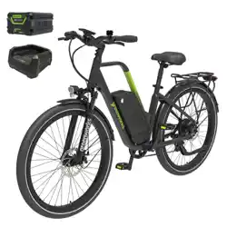
E-BIKE
E-BIKE
BICICLETA ELÉCTRICA

1 Introduction................................. 2
1.1 Product description.....................................2
1.2 Intended use...............................................2
1.3 Overview ................................................... 2
1.4 Symbols on the product..............................5
1.5 California Proposition 65............................ 5
2 Safety............................................5
2.1 Safety definitions........................................ 5
2.2 Important safety instructions...................... 5
2.3 Save these instructions.............................. 7
2.4 FCC Requirement...................................... 7
3 Assembly..................................... 7
3.1 Install the handlebar................................... 7
3.2 Install the front wheel................................. 8
3.3 Install the pedals........................................ 8
4 Operation..................................... 9
4.1 Before you ride........................................... 9
4.2 Start the product....................................... 11
4.3 Headlight on/off.........................................11
4.4 Activate walk-assist mode........................ 11
4.5 Shift gears................................................ 12
4.6 Stop the product....................................... 13
5 Display settings.........................13
5.1 Display interface switch............................13
5.2 Display brightness settings.......................14
5.3 Unit conversion settings........................... 14
5.4 Trip distance reset.................................... 15
5.5 Factory reset............................................ 15
6 SMARTg home application.......16
6.1 Setup........................................................ 16
7 Maintenance...............................16
7.1 Maintenance schedule............................. 16
7.2 Clean the product..................................... 16
7.3 Clean the battery and battery charger......17
8 Transportation, storage and
disposal......................................17
8.1 Transportation.......................................... 17
8.2 Storage.....................................................17
8.3 Disposal of the battery, battery
charger, and product................................ 17
9 Error codes................................ 17
10 Technical data............................18
11 Limited warranty........................18
11.1 Items not covered by warranty................. 19
11.2 Helpline.................................................... 19
11.3 Shipping................................................... 19
1
English (Original Instructions)
EN
1 INTRODUCTION
Thank you for choosing to purchase the greenworks
®
e-bike. Our top priority is to inform you about the potential risks
associated with riding an e-bike, to ensure that you have a safe and enjoyable riding experience for many years to
come.
WARNING
BEFORE RIDING YOUR E-BIKE OR ALLOWING ANYONE ELSE TO RIDE IT, PLEASE CAREFULLY READ
THIS ENTIRE MANUAL. IT IS ALSO ESSENTIAL FOR OTHERS TO READ THIS MANUAL BEFORE RIDING
YOUR E-BIKE WITH YOUR PERMISSION.
If you have any concerns, questions, or suggestions about your electric bike, please contact us at 1-855-345-3934.
1.1 PRODUCT DESCRIPTION
This product is a battery-operated bike with an electric motor. We have a policy of continuous product development
and therefore reserve the right to modify the design and the appearance of the products without prior notice.
1.2 INTENDED USE
This electric bike is a motorized bicycle with an integrated electric motor used to assist propulsion and is designed to
give maximum comfort over a wide variety of road surfaces.
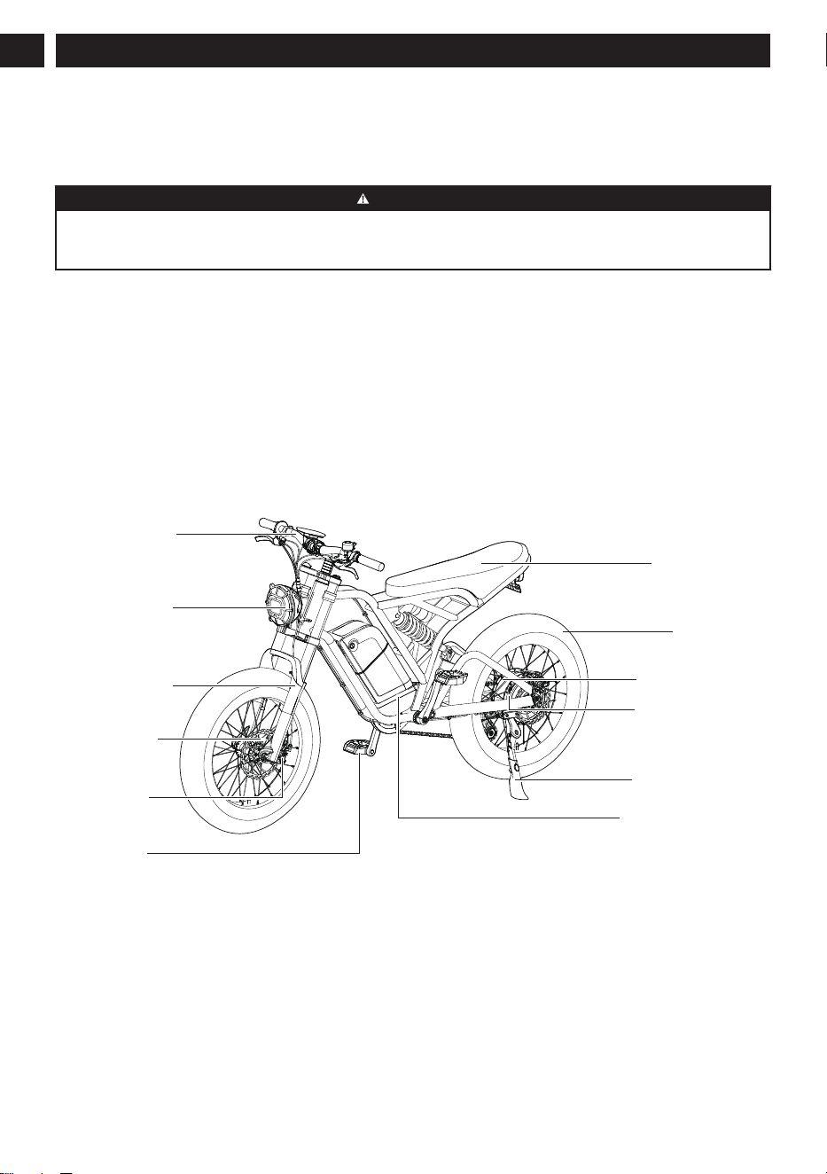
1.3 OVERVIEW
E-bike
1
2
3
4
5
6
7
12
11
10
9
8
1
Handlebar
2
Headlight
3
Front fork
4
Front disc brake
5
Brake caliper
6
Pedal
7
Battery box
8
Kickstand
9
7-speed derailleur
10
Rear-hub motor
11
Tire
12
Saddle
2
English (Original Instructions)
EN
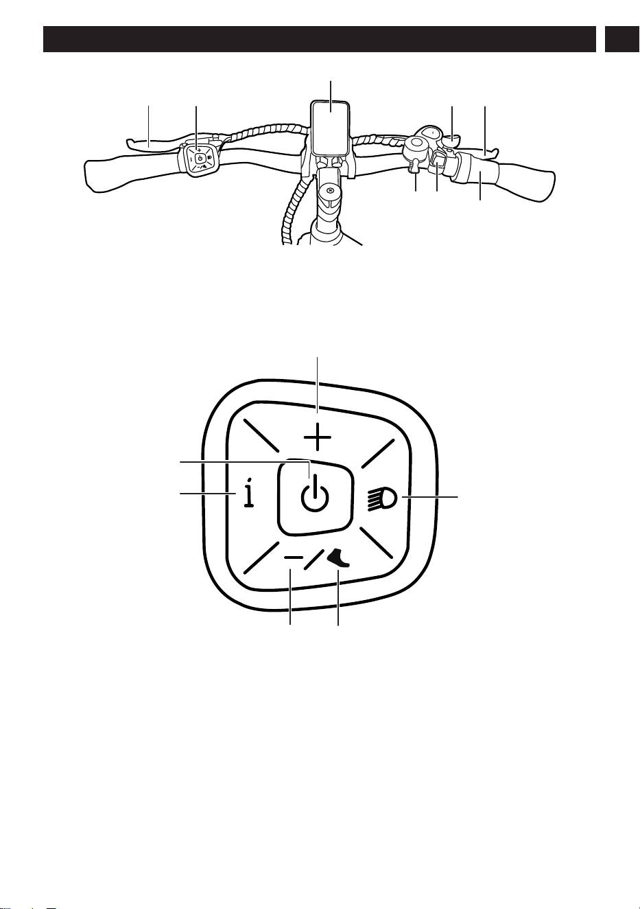
1
2
3
4
5
6
7
1514
19
17
2021
18
16
14
Front brake lever
15
Button panel
16
LCD display
17
Gear shift lever (-)
18
Rear brake lever
19
Throttle
20
Gear shift button (+)
21
Bell
Button panel
27
23
24 25
26
22
22
On/off button
23
Parameter setting button
24
PAS (Pedal-assist sensor) decrease button
25
Walk-assist button
26
Headlight button
27
PAS (Pedal-assist sensor) increase button
3
English (Original Instructions)
EN
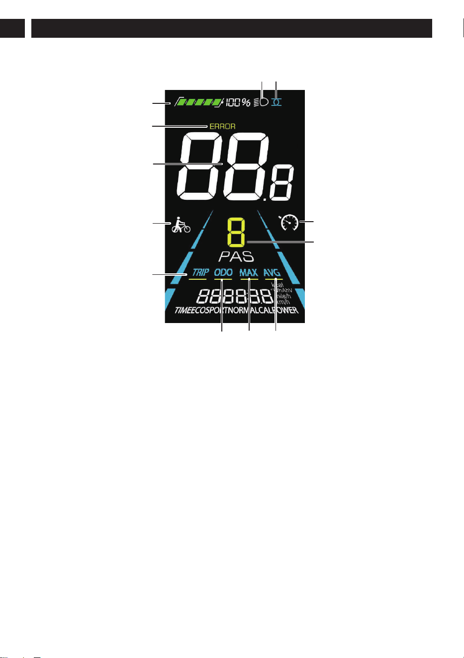
Display
28
36 37
33 34 35
38
39
29
30
31
32
28
Battery level
29
Error
30
Speed
31
Walk-assist symbol
32
Trip distance
33
Odometer
34
Maximum speed
35
Average speed
36
Headlight
37
Bluetooth
38
Cruise control
39
PAS level
Toolkit
5 Hex keys: M2.5, M3, M4, M5, M6
1 Phillips Screwdriver
3 Wrenches: 10mm, 15mm (2)
4
English (Original Instructions)
EN
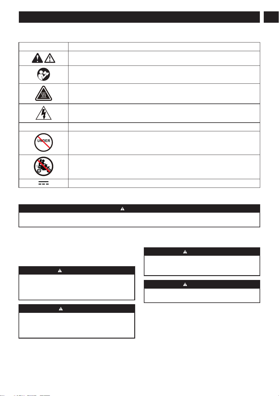
1.4 SYMBOLS ON THE PRODUCT
Symbol Explanation
Important safety precautions.
Read instructions thoroughly before operating the product and follow all warnings and
safety instructions.
Burn hazard. The hub motor will get hot during normal use. Do not touch.
Warning: Electric shock hazard.
IPX4 Waterproof level.
14
Never permit children under age 14 to operate this product. Operation by children under
the age of 14 increases the risk of severe injury or death. Adult supervision required for
children under the age of 16.
Do not ride with a passenger. Passengers can cause a loss of control, resulting in severe
injury or death.
Direct current
1.5 CALIFORNIA PROPOSITION 65
WARNING
THIS PRODUCT CONTAINS OR EMITS A CHEMICAL KNOWN TO THE STATE OF CALIFORNIA TO CAUSE
CANCER OR BIRTH DEFECTS OR OTHER REPRODUCTIVE HARM.
2 SAFETY
2.1 SAFETY DEFINITIONS
Warnings, cautions, and notes are used to point out
especially important parts of the manual.
WARNING
USED IF THERE IS A RISK OF INJURY OR
DEATH FOR THE OPERATOR OR BYSTANDERS IF
THE INSTRUCTIONS IN THE MANUAL ARE NOT
OBEYED.
CAUTION
USED IF THERE IS A RISK OF DAMAGE TO
THE PRODUCT, OTHER MATERIALS, OR THE
ADJACENT AREA, IF THE INSTRUCTIONS IN THE
MANUAL ARE NOT OBEYED.
Note: Used to give more information that is necessary
in a given situation.
2.2 IMPORTANT SAFETY
INSTRUCTIONS
WARNING
NEW AND EXPERIENCED RIDERS SHOULD
ALWAYS EXERCISE CAUTION WHEN USING THIS
PRODUCT.
WARNING
READ AND UNDERSTAND THE SAFETY CHAPTER
BEFORE YOU ASSEMBLE THE PRODUCT.
General safety warnings
When using this product, basic precautions should
always be followed, including the following:
• Read all the instructions before using the product.
• To reduce the risk of injury, close supervision is
necessary when the product is used near children.
• Keep hands and feet away from moving tire and
wheel to prevent pinching.
5
English (Original Instructions)
EN

• Do not use this product if the flexible power cord or
output cable is frayed, has broken insulation, or any
other signs of damage.
• This product is only safe to use when the
temperature is between 32°F (0°C) and 104°F
(40°C). The battery should only be charged when
the temperature is between 32°F (0°C) and 104°F
(40°C).
• Do not modify or repair the product unless the
instructions for use and care allow it.
Safety tips
• Before every ride, it is important to thoroughly
inspect your product for any potential issues and
ensure regular maintenance is performed. If you are
uncertain about how to conduct a comprehensive
safety check or assess the condition of your
product, it is recommended to seek assistance from
a certified and reputable product mechanic. They
can provide guidance and help you ensure the
safety and proper functioning of your product.
• Always wear a helmet that meets safety standards
to avoid serious injury or death. Approved helmets
in the USA must meet the US Consumer Product
Safety Commission standard. Helmets sold in
Canada are certified by CSA (Canadian Standards
Association), CPSC (Consumer Product Safety
Commission), Snell or ASTM (American Society for
Testing and Materials).
• Before each use, it is crucial to ensure that this
product is assembled correctly, and that the rider
conducts a safety check.
• Check the brake motor cutoff before each ride
to ensure it is working properly. When properly
functioning, the brake system should cut off power
to the motor whenever the brakes are squeezed.
• Take the time to familiarize yourself with the pedal
assistance and throttle functions of the products.
The pedal-assist sensor (PAS) provides a significant
boost to your pedaling, with the power level
determined by the PAS level selected on the control
panel.
• We strongly recommend reading the manual to
familiarize yourself with the location of control knobs
and to understand the purpose of each function.
• Start by using the lowest pedal-assist level or the
lightest throttle setting until you feel comfortable with
the product.
• Maintain a safe riding speed that is suitable for
the weather conditions, the type of terrain you are
traversing (such as loose gravel and dirt), and
your level of experience with using pedal-assisted
e-bikes.
• It is highly recommended to wear safety gear,
including an ANSI-approved riding helmet, gloves,
and safety boots when operating this product.
Additionally, for outdoor rides on remote and
unfamiliar trails, it is advisable to have a companion
with you for added safety and support.
• Only transport the product using racks that are
specifically rated for its size and weight.
• Avoid performing large jumps or stunts. Refrain from
reckless driving and ensure that the product remains
on both wheels at all times. Note that the product is
not intended for submerging in water.
• In the event of a collision or if the product is
suspected to be damaged, refrain from riding it
until a certified mechanic conducts a thorough
inspection.
• Follow the instructions for installation, compatibility,
operation, and maintenance to avoid serious injury
or death.
• Any aftermarket changes or modifications to your
product can void the warranty and potentially result
in an unsafe riding experience.
• Ride at night only if necessary. Be sure to wear
reflective clothing, and ensure your product has
reflectors and lights as required by local laws.
• Decrease speed and increase braking distance in
wet conditions.
• It is your responsibility to understand the local
regulations for operating this product in the area(s)
where you ride.
• Never operate your product when you are under the
influence of alcohol or drugs, including prescribed or
over the counter medications.
• Properly charge, store, and use the battery to avoid
hazards. Failure to do so may be hazardous and/or
void the warranty.
• Failure to perform and confirm proper installation,
compatibility, proper operation, or maintenance of
any component or accessory can result in serious
injury or death.
• Extreme care should be taken when using the
pedal-assist sensor and throttle on this product.
Ensure you understand and are prepared for the
power assistance to engage as soon as pedaling is
underway.
• Always use the lowest assist level until you are
comfortable with the product and feel confident in
controlling the power.
• If you have any impairments or disabilities, consult
your physician before riding.
• Keep all body parts and other loose objects away
from moving parts of the product.
• Do not remove any reflectors or the bell.
• Please note that this product carries inherent risks
and can be dangerous to use. By using this product,
the user assumes all responsibility for personal
injuries, damages, product, or system failures, as
well as any losses or damages to themselves,
others, or property that may arise from its use.
It is important to understand that all mechanical
components are subject to wear and high stresses.
6
English (Original Instructions)
EN
Different materials and components may respond
differently to wear and stress fatigue. If a component
has exceeded its designed lifespan, it may fail
unexpectedly and potentially cause harm to the
rider. Therefore, any signs of cracks, scratches, or
color changes in highly stressed areas indicate that
the component has reached the end of its lifespan
and should be replaced immediately.
Local laws
Rules for electric bikes vary depending on the rider's
location. In some places, they follow the same rules
as regular bikes. However, different areas may have
specific laws for electric bikes, including licenses, age
limits, where you can ride, and required equipment
such as helmets. The rider should know and follow the
regulations that apply to electric bikes in their area.
2.3 SAVE THESE INSTRUCTIONS
2.4 FCC REQUIREMENT
This device complies with part 15 of the FCC Rules.
Operation is subject to the following two conditions:
1. This device may not cause harmful interference, and
2. This device must accept any interference received,
including interference that may cause undesired
operation.
WARNING
ANY CHANGES OR MODIFICATIONS NOT
EXPRESSLY APPROVED BY THE PARTY
RESPONSIBLE FOR COMPLIANCE COULD VOID
THE USER’S AUTHORITY TO OPERATE THE
EQUIPMENT AND ITS WARRANTY.
Note: This equipment has been tested and found to
comply with the limits for a Class B digital device,
pursuant to Part 15 of the FCC Rules. These limits
are designed to provide reasonable protection against
harmful interference in a residential installation. This
equipment generates, uses, and can radiate radio
frequency energy, and if not installed and used in
accordance with the instructions, may cause harmful
interference to radio communications. However, there
is no guarantee that interference will not occur in a
particular installation. If this equipment does cause
harmful interference to radio or television reception,
which can be determined by turning the equipment off
and on, the user is encouraged to try to correct the
interference by one or more of the following measures:
• Reorient or relocate the receiving antenna.
• Increase the separation between the equipment and
receiver.
• Connect the equipment into an outlet on a
circuit different from that to which the receiver is
connected.
• Consult the dealer or an experienced radio/TV
technician for help.
3 ASSEMBLY
This section describes how to assemble and adjust the
product.
WARNING
CAREFULLY READ AND UNDERSTAND THE
SAFETY CHAPTER AND THE ASSEMBLY
INSTRUCTIONS BEFORE YOU ASSEMBLE THE
PRODUCT.
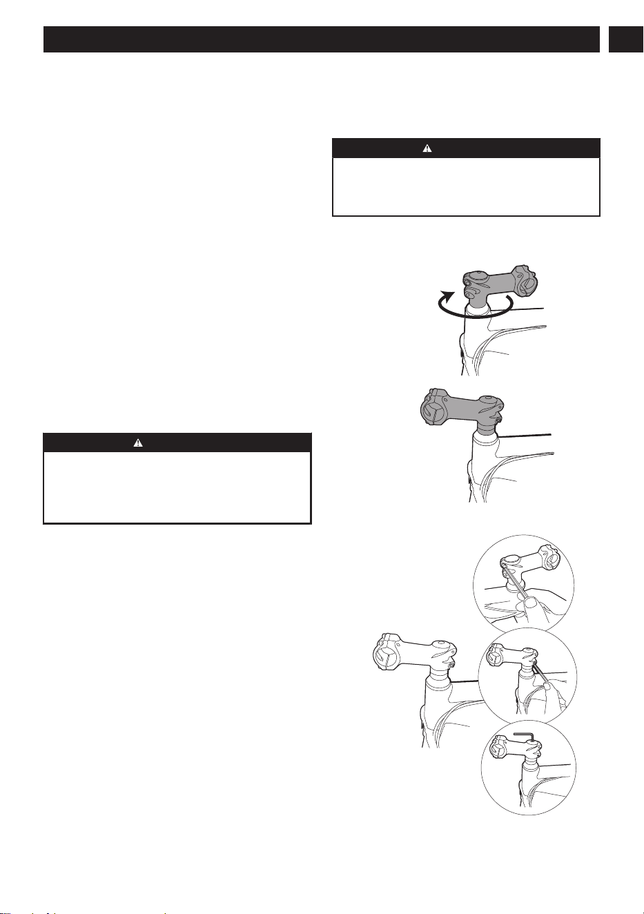
3.1 INSTALL THE HANDLEBAR
1. Rotate the handlebar stem 180° to face it forward.
180°
2. Use three bolts to tighten and secure the stem in
position.
3. Unscrew 4 bolts from the stem cover.
7
English (Original Instructions)
EN
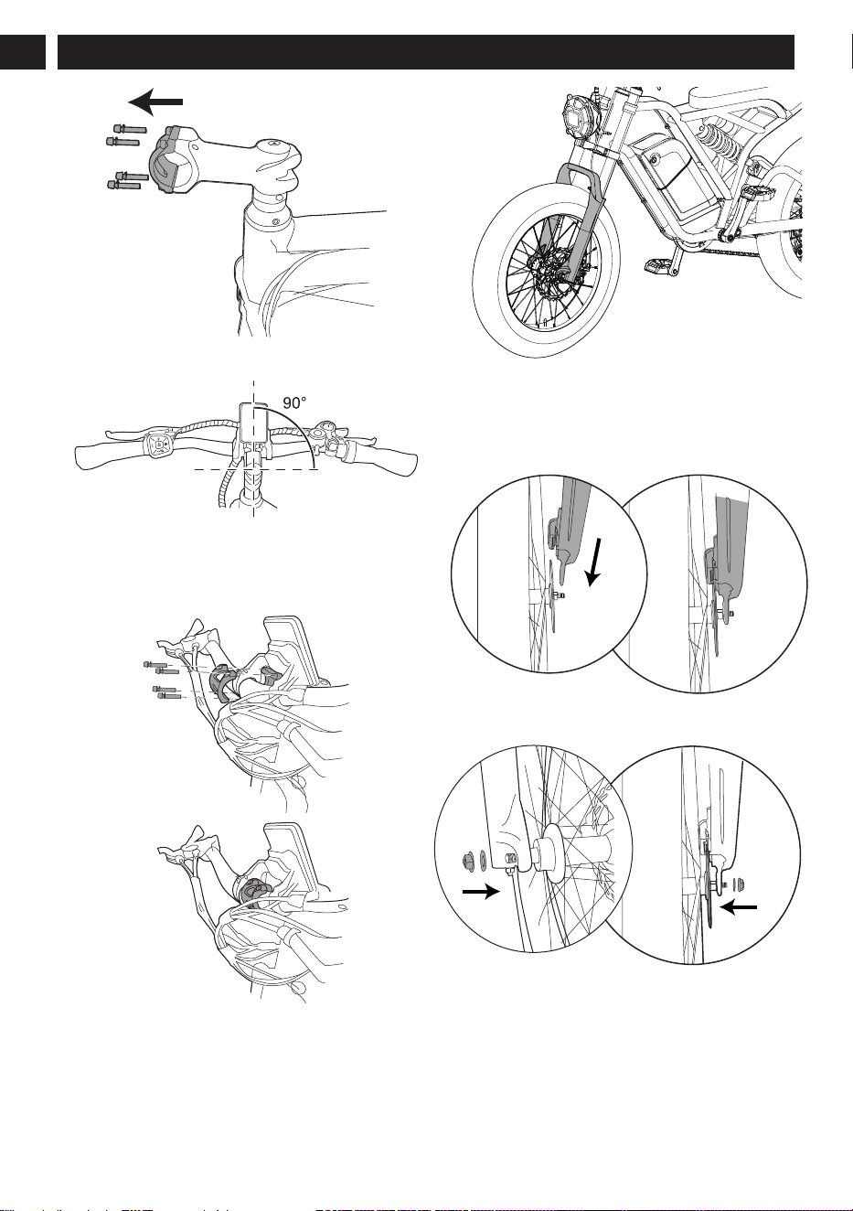
4. Place the handlebar onto the stem and make sure it
is perpendicular to the bike frame.
5. Utilize a crisscross tightening pattern for the
bolts, which involves tightening them in a diagonal
sequence rather than tightening them sequentially.
This method ensures a secure and well-balanced
grip on the handlebar.
3.2 INSTALL THE FRONT WHEEL
1. Insert the front wheel between the front fork.
Note: • The disc brake is on the left side of the
bike, in the direction of travel.
• Ensure that the front wheel axle is fully
inserted into the slot of the front fork.
2. Check that the disc brake fits into the brake caliper.
3. Put the washers onto the axle and use the locknuts
to tighten them securely.
3.3 INSTALL THE PEDALS
1. To identify the correct side of the pedals, look for the
letters 'R' and 'L' that are marked on the pedals.
8
English (Original Instructions)
EN
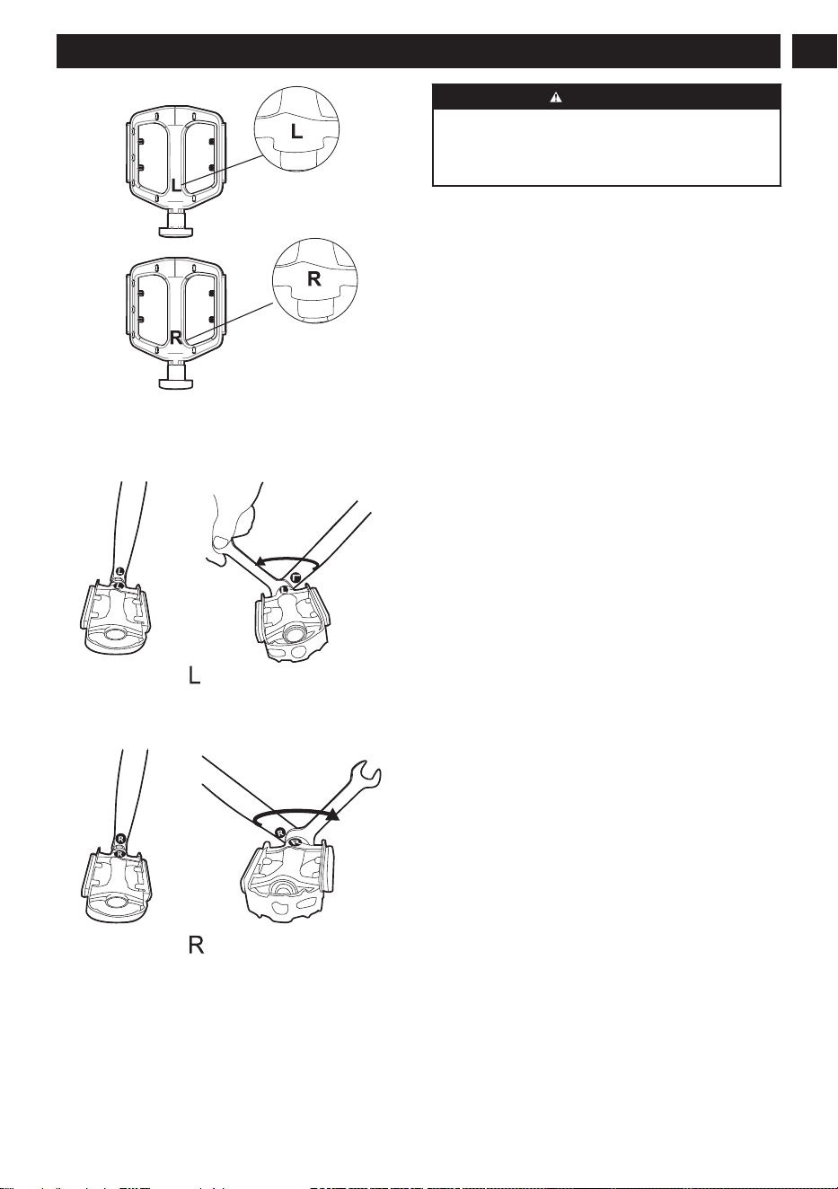
2. Screw the pedals onto the crank arms and use the
wrench to tighten them securely.
Note: Left pedal should be tightened counter-
clockwise.
4 OPERATION
This section describes how to operate the product.
WARNING
CAREFULLY READ AND UNDERSTAND
THE SAFETY CHAPTER AND OPERATION
INSTRUCTIONS BEFORE YOU OPERATE THE
PRODUCT.
4.1 BEFORE YOU RIDE
4.1.1 PRE-RIDE CHECKLIST
Make sure to check the condition of the product before
each ride.
Brakes
• Ensure front and rear brakes work properly.
• Ensure brake shoe pads are not overworn and are
correctly positioned in relation to the rims.
• Ensure brake control cables are lubricated properly,
adjusted correctly, and are not showing any obvious
signs of wear.
• Ensure brake control levers are tightened securely
onto the handlebar.
Steering
• Ensure that the handlebar and stem are
appropriately adjusted and tightened to enable
safe and proper steering. Refer to INSTALL THE
HANDLEBAR.
Wheels and Tires
• Ensure tires are inflated to within the maximum
recommended limit displayed on the tire sidewall.
• Ensure tires have tread and no bulges or excessive
wear.
• Ensure rims are not bent and show no obvious
wobbles or kinks.
• Ensure all wheel nut spokes are securely tightened
and visually inspect for broken or missing pieces.
• Check that axle nuts are tight. Refer to INSTALL
THE FRONTWHEEL.
Chain
• Ensure chain is oiled, clean and runs smoothly.
Derailleur
• Check that front and rear guide pulley and tension
pulley are adjusted and function properly.
• Ensure control levers are attached securely.
• Ensure derailleur, shift levers, and control cables are
lubricated properly.
4.1.2 CHOOSE THE RIGHT BIKE HELMET
Make sure to comply with the local laws and always
wear a helmet when riding this product. It is crucial
to wear a bicycle safety helmet that fits correctly and
is approved by the CPSC (Consumer Product Safety
Commission) to ensure the highest level of safety while
cycling.
9
English (Original Instructions)
EN
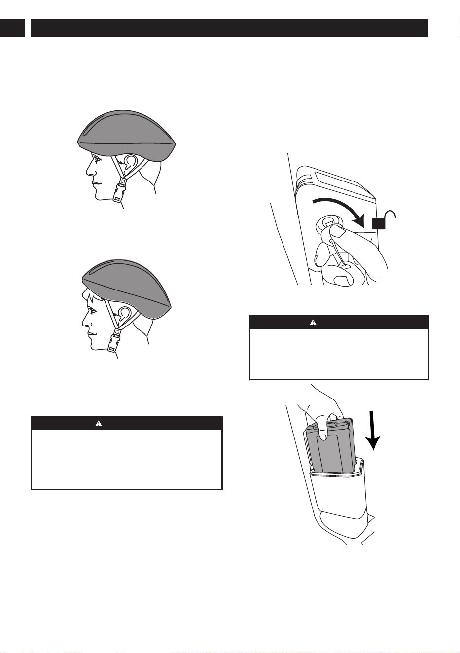
The correct helmet should:
• be comfortable
• be lightweight
• have good ventilation
• fit correctly
CORRECT FITTING
MAKE SURE YOUR HELMET COVERS YOUR
FOREHEAD.
INCORRECT FITTING
FOREHEAD IS EXPOSED AND VULNERABLE TO
SERIOUS INJURY.
WARNING
ALL STATES/COUNTRIES REQUIRE BICYCLISTS
ON THE ROADWAY TO FOLLOW THE
SAME RULES AND RESPONSIBILITIES AS
MOTORISTS. WEAR ANSI/NHTSA/NCBI/NIM/NIH/
CPSC APPROVED RIDING GEAR AND OBEY ALL
LAWS APPLICABLE IN YOUR AREA.
4.1.3 CONNECT THE BATTERY CHARGER
1. Connect the battery charger to the proper voltage
and frequency that is specified on the rating plate.
2. Refer to the Battery Charger Operator Manual for
information about how to use the battery charger.
4.1.4 CHARGE THE BATTERY
Refer to the Battery Charger Operator Manual for
information about how to use the battery charger.
4.1.5 BATTERY INFORMATION
Refer to the Battery Operator Manual for information
about how to use the battery.
4.1.6 CONNECT THE BATTERY TO THE
PRODUCT
Ensure the battery is fully charged before operating.
1. To remove the cover, insert the key and rotate it
clockwise to the UNLOCK position.
2. Push the battery into the battery compartment. The
battery locks into position when you hear a click.
CAUTION
IF THE BATTERY DOES NOT FIT EASILY INTO
THE BATTERY HOLDER, IT MAY NOT BE
INSTALLED CORRECTLY, WHICH CAN CAUSE
DAMAGE TO THE BATTERY AND/OR THE
PRODUCT.
3. Rotate the key to the UNLOCK position and hold it
in place. Align the cover with the battery box and
push it firmly along the ribs until it locks into place.
10
English (Original Instructions)
EN
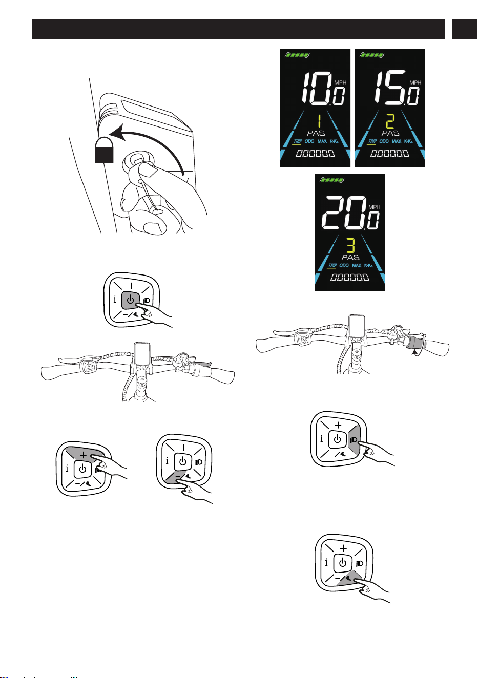
4. Withdraw the key to remove it from the lock. Always
make sure the battery cover is securely in position
before riding the bike.
4.2 START THE PRODUCT
1. Press and hold the on/off button to power on.
2. Activate the product by squeezing the brake lever.
3. Select the riding assist level by pressing the PAS
adjust button (+/-).
Note: The default gear is 0, and you can choose
a level from 1 to 3. A higher gear provides faster
acceleration.
mile
mile
mile
4. Place both hands on the handlebar. Gently turn the
throttle inward to start your trip.
4.3 HEADLIGHT ON/OFF
• Press the headlight button to turn on the headlight.
• Press the headlight button again to turn off the
headlight.
4.4 ACTIVATE WALK-ASSIST MODE
• To activate walk-assist mode, press and hold the
walk-assist button until the product starts moving.
11
English (Original Instructions)
EN
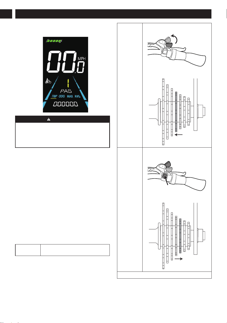
• When using walk-assist mode, the bike will move
at a constant speed of 2.5 mph (4 km/h). The walk-
assist symbol will be displayed on the screen.
mile
WARNING
ONLY ACTIVATE WALK-ASSIST MODE WHEN
WALKING ON A SLOPE. MOUNTING OR RIDING
THE PRODUCT WHILE IN WALK-ASSIST MODE
CAN INCREASE THE RISK OF INJURY DUE TO
POTENTIAL LOSS OF BALANCE.
• Release the walk-assist button to disengage the
walk-assist mode.
4.5 SHIFT GEARS
Note: The gear system comprises a network of levers,
guides, and tension pulleys that facilitate the movement
of the drive chain between the 7 sprockets located
at the rear wheel. Its primary function is to help you
maintain a consistent and smooth pedaling rhythm
across different terrains, reducing the effort required
when cycling uphill or downhill.
Note: Do not shift derailleur gears when you are
stopped. For a smooth gear change when approaching
a hill, shift to a lower gear before your pedaling speed
slows down too much. When coming to a stop, shift to a
lower gear first so it will be easier when you start riding
again. For optimal performance and extended chain
life, it is recommended that you avoid using extreme
combinations of gear positions for extended periods.
Pedaling
state
Operation
Pedaling be-
comes lighter
Push lever to shift through each of the
gears (i.e. 5 to 4).
1
2
3
4
5
6
7
Rear sprocket shifts from smaller to
larger (i.e. 5th to 4th).
5
4
Pedaling be-
comes heavi-
er
Push the button to shift through each of
the gears (i.e. 4 to 5).
1
2
3
4
5
6
7
Rear sprocket shifts from a larger to
smaller (i.e. 4th to 5th).
5
4
Note: To change gears, you must be pedaling forward.
12
English (Original Instructions)
EN
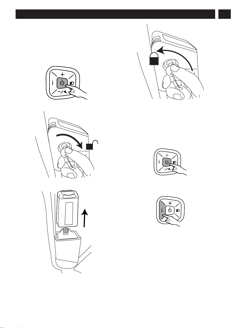
4.6 STOP THE PRODUCT
1. Release the throttle and squeeze the brake lever to
stop the product.
Note: When coming to a complete stop, place both
feet on the ground to balance the product.
2. If ride is complete, press and hold the on/off button
to power off.
3. Insert the key, turn it clockwise to the UNLOCK
position and remove the cover.
4. Remove the battery from battery box by pushing the
battery release button.
5. Rotate the key to the UNLOCK position and hold it
in place. Align the cover with the battery box and
push it firmly along the ribs until it locks into place.
6. Withdraw the key to remove it from the lock.
5 DISPLAY SETTINGS
Note: Set the parameters only when the product is
stopped.
5.1 DISPLAY INTERFACE SWITCH
1. Press the on/off button to turn on the display,
which shows the real-time speed (mph) and the trip
distance (mile) by default.
2. Press the parameter setting button to toggle the
display interface between the trip distance (mile),
ODO (mile), maximum speed (mph) and average
speed (mph).
13
English (Original Instructions)
EN
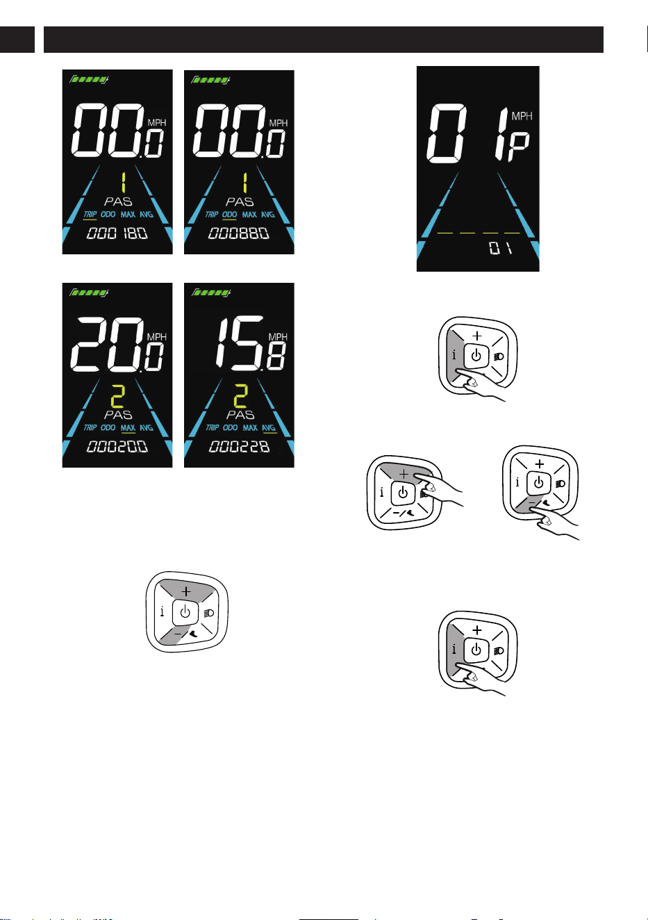
mile
mile
Trip distance ODO
mile/h
mile/h
Maximum speed Average speed
5.2 DISPLAY BRIGHTNESS SETTINGS
1. Press and hold both the plus and minus buttons for
more than two seconds to enter the custom setting
interface.
2. The display will show "01P."
3. Press the parameter setting button to enter
parameter modification area (located at the left of
the display).
4. Use the plus/minus buttons to select the desired
brightness level.
Note: "00" is the darkest, and "03" is the brightest.
5. Press the parameter setting button to save the new
brightness level.
6. Press and hold the parameter setting button for
more than two seconds to exit.
5.3 UNIT CONVERSION SETTINGS
1. Press and hold both the plus and minus buttons for
more than two seconds to enter the custom setting
interface.
14
English (Original Instructions)
EN
should
this
be on
PAS
3?
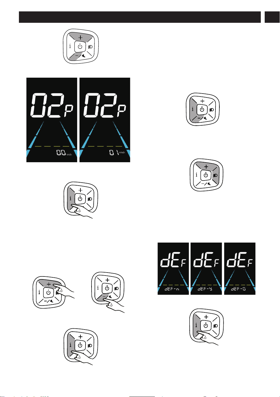
2. Press the plus button to enter the selection interface
of "02P".
3. Press the parameter setting button to enter
parameter modification area (located at the bottom
of the display).
4. Press the plus/minus button to select desired unit
preference.
Note:
"00": metric system (km/h)
"01": imperial system (mile/h)
5. Press the parameter setting button to save the new
unit preference.
6. Press and hold the parameter setting button for
more than two seconds to exit.
5.4 TRIP DISTANCE RESET
The display can record single trip mileage and total
mileage. It is able to clear the single trip mileage, but
not able to clear total mileage.
1. Press and hold both the parameter setting button
and minus button for more than two seconds to
reset the trip distance.
5.5 FACTORY RESET
1. Press and hold both the plus and headlight buttons
for more than two seconds to enter the factory reset
interface.
2. Press the plus/minus button to select "dEF-y".
Note:
"dEF-0": Device will be factory reset.
"dEF-n": Factory settings will not be restored.
"dEF-y": Factory setting will be restored.
3. Select "def-y" using the plus/minus button. Then
press the parameter setting button to confirm.
4. The display will show "dEF-0" and automatically
begin to restore the factory default settings.
15
English (Original Instructions)
EN
5. After the default settings have been restored,
the device will automatically exit the factory reset
interface.
6 SMARTG HOME APPLICATION
SMARTg Home is a free mobile application that
provides additional features for your product.
6.1 SETUP
Note: Always set up first before riding.
1. Download the SMARTg Home app on your mobile
device.
2. Register in the SMARTg Home app.
3. Follow the instructions in the SMARTg Home app to
connect and register the product.
Note: Ensure that your phone's Bluetooth function is
always on.
7 MAINTENANCE
IMPORTANT
CAREFULLY READ AND UNDERSTAND THE SAFETY REGULATIONS AND THE MAINTENANCE
INSTRUCTIONS BEFORE YOU CLEAN, REPAIR, OR DO ANY MAINTENANCE ON THE PRODUCT.
WARNING
• REMOVE BATTERY OR BATTERIES FROM THE PRODUCT BEFORE YOU DO ANY MAINTENANCE.
• FAILURE TO FOLLOW PROPER MAINTENANCE SERVICE, USING THIRD-PARTY REPLACEMENT
PARTS, OR MODIFYING/REMOVING COMPONENTS CAN RESULT IN INJURY TO THE USER.
7.1 MAINTENANCE SCHEDULE
Item Before each use
First 20 hours of use or 1
month
After 3000 miles (5000 km)
or 1 year
Brake I I
Wheels and tires I I
Saddle I
Cranks and pedals I I
Chain I I
Bearings I I
Handlebar and stem I I I
Frame and fork I I
Derailleur I I
Nuts and bolts I I T
Note: I = inspect and clean, adjust, replace or lubricate as necessary, T = tighten
It is recommended that this be done by an authorized service center.
7.2 CLEAN THE PRODUCT
CAUTION
• KEEP WATER AWAY FROM BATTERY COMPARTMENT WHILE WASHING TO AVOID DAMAGING THE
ELECTRICAL COMPONENTS.
• DO NOT CLEAN WITH ALCOHOL, GASOLINE, ACETONE, OR OTHER CORROSIVE/VOLATILE
SOLVENTS. THESE SUBSTANCES MAY DAMAGE THE EXTERNAL AND INTERNAL STRUCTURE OF
YOUR PRODUCT.
• DO NOT RUB WITH SANDPAPER OR METAL BRUSH.
CLEAN THE PRODUCT AFTER EACH USE WITH WATER, NEUTRAL DETERGENT, AND A SOFT CLOTH.
16
English (Original Instructions)
EN

7.3 CLEAN THE BATTERY AND BATTERY CHARGER
WARNING
DO NOT CLEAN THE BATTERY OR THE BATTERY CHARGER WITH WATER.
• Make sure that the battery and the battery charger and battery compartment are all clean and dry before you
insert the battery into the battery charger.
• Clean the battery terminals with a soft and dry cloth.
• Clean the surface of the battery and the battery charger with a soft and dry cloth.
8 TRANSPORTATION, STORAGE AND DISPOSAL
8.1 TRANSPORTATION
• Any removable (electronic) parts, such as the charger and battery, should always be disconnected before
transport.
• Avoid transporting the product in bad weather conditions when possible.
• Make sure to adequately cover any exposed electronic parts if transportation in adverse weather conditions is
unavoidable.
• Use tape on open contacts of the battery and ensure it is securely stowed to prevent movement.
• High speeds, along with wind, and rain may force moisture into the electronic components, which can lead to
temporary malfunctions or permanent defects.
• In case of malfunction occurring after transport in such conditions, remove the battery and allow all parts to
air-dry when you reach your destination.
8.2 STORAGE
• Turn off the product and remove the batteries.
• Thoroughly clean the product and then wax the painted parts with a non-abrasive automotive wax.
• Inflate the tires with correct air pressure. Refer to PRE-RIDE CHECKLIST.
• Store the product in a covered shed or garage to protect it from dust, dirt, and humidity. If the product must be
stored outdoors, cover it completely with a waterproof cover.
• Store the product in a safe place to prevent theft.
8.3 DISPOSAL OF THE BATTERY, BATTERY CHARGER, AND PRODUCT
Symbols on the product or the package of the product identify that the product is not domestic waste. Recycle it
at a recycling station for electrical and electronic equipment. This helps to prevent damage to the environment and
persons.
For guidance on proper disposal, recycling instructions, and information regarding recycling your product, you can
reach out to your local domestic waste service or dealer. Additionally, you may contact the Environmental Protection
Agency (EPA) for disposal instructions specific to North America.
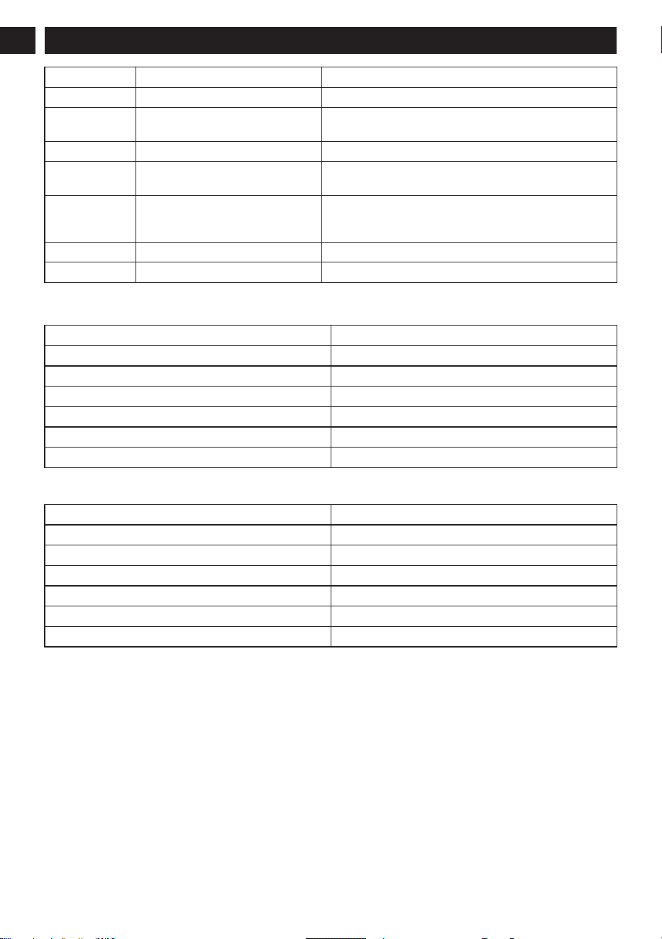
9 ERROR CODES
It is important to troubleshoot any faults in the electronic control system of your product as soon as possible to
ensure safe and proper operation. The error codes listed in the manual provide a helpful guide for identifying and
resolving any issues. Below are the detailed definitions and solutions for each error code.
17
English (Original Instructions)
EN
Error code Definition Solution
E001 Controller Abnormality Contact dealer for assistance.
E002
Communication Abnormality
Check the motor plug. If everything is in order, contact
dealer for assistance.
E003 Motor Hall Signal Abnormality Contact dealer for assistance.
E004 Throttle Abnormality Check whether the throttle is in place. If everything is in
order, contact dealer for assistance to replace the throttle.
E005 Brake Abnormality Check whether the brake is in place. If everything is in
order, contact dealer for assistance to replace the brake
lever.
E006 Motor Phase Abnormality Contact dealer for assistance.
E012 Battery Voltage Abnormality Use the battery with the correct voltage.
10 TECHNICAL DATA
Voltage 80V DC
Max. payload 300 lbs. (136 kg)
Minimum rider age 14 years old
Maximum speed 20 mph (32 km/h)
Maximum slope 10°-12°
Battery model BAB727 and other BAB series
Charger model CAB801 and other CAB series
The recommended ambient temperature range:
Item
Temperature
Product storage temperature range 32°F (0°C) - 113°F (45°C)
Product operation temperature range 32°F (0°C) - 104°F (40°C)
Battery charging temperature range 39°F (0°C) - 104°F (40°C)
Charger operation temperature range 39°F (0°C) - 104°F (40°C)
Battery storage temperature range 32°F (0°C) - 113°F (45°C)
Battery discharging temperature range 32°F (0°C) - 104°F (40°C)
11 LIMITED WARRANTY
greenworks
®
products are warrantied against all
defects in materials, parts, or workmanship under
normal use for a period of 18 months from the shipping
date or in-store purchase date.
At its own discretion, greenworks
®
can opt to repair,
replace, substitute with a comparable item, or issue a
refund for products that are determined to be defective
through normal use or that have been damaged during
shipment. Proof of purchase and product registration
is required. Replacement of products or parts subject
to normal wear and tear is the responsibility of the
customer.
This warranty is valid only for units which have been
maintained in accordance with the instructions found in
the operator manual supplied with the product; and for
units which have been registered in one of the following
ways:
Online:
greenworkstools.com/product-registration
1-855-345-3934
If greenworks
®
accepts a return under warranty,
you can return the damaged product only after
you call our Customer Care team and receive
a Return Authorization from greenworks
®
. You
will receive a refund for your original shipping
charges, and greenworks
®
will arrange and pay for
your return shipping charges. To request a Return
18
English (Original Instructions)
EN

Authorization, please contact us at 1-888-90-WORKS or
(1-855-345-3934).
11.1 ITEMS NOT COVERED BY
WARRANTY
• Any part that has become inoperative due to
misuse, commercial use, abuse, neglect, accident,
improper maintenance, or alteration
• The unit, if it has not been operated and/or
maintained in accordance with the operator manual
• Normal wear, except as noted below:
• Routine maintenance items such as lubricants.
• Normal deterioration of the exterior finish due to
use or exposure.
• Any part/product, that has become inoperable
due to use with any non-greenworks
®
-
branded parts or batteries/chargers.
11.2 HELPLINE
Warranty service is available by calling our toll-free
helpline at: 1-855-345-3934.
11.3 SHIPPING
Transportation charges for the movement of any power
equipment unit or attachment are the responsibility of
the purchaser. It is the purchaser’s responsibility to
pay transportation charges for any part submitted for
replacement under this warranty unless such return is
requested in writing by greenworks
®
.
11.3.1 ADDRESS
USA address:
greenworks
®
North America, LLC
P.O. Box 1238
Mooresville, NC 28115
Canada address:
greenworks
®
Tools Canada, Inc.
P.O. Box 93095
Newmarket, Ontario, L3Y 8K3
Mexico address:
Tecnologia Campo y Jardin S.A. de C.V.
C. Administradores 5336 A
Col. Arcos de Guadalupe
Zapopan, Jalisco, 45037
19
English (Original Instructions)
EN