
iSCAN NX
Features Overview
iSCAN NX Hardware Features
N
NX
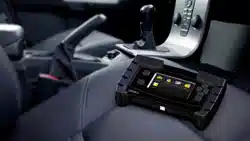
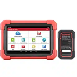
iSCAN NX Base Unit (Tablet)
USB-C
U5B-A
Use-c
9
PS-C3 USB-C Cable(1.8M/70*in)
E]
iSCAN VCI BOX
BU-EC-3DC-to-DC Power Cable(1.8M/70"in)
Initial Tool Setup
Software Update
DC-12V
&Initial StartUp
Switching
```markdown```
Tool Initial Setup Instructions
1.Connect to Wi-Fi:
○ From the main screen, select SETUP.
☆
o Choose Wi-Fi and connect to your shop's Wi-Fi.
o Return(exit) to the SETUP options.
2.Update Company Information:
o Scroll down and select Company.
o Choose Edit My Company and enter your shop's info.
fo.
o Return(exit) to the SETUP options.
3.
3.Set Date &Time:(
o Select Date &Time.
○ Adjust the Time Zone for your location.
(This step is important for certain vehicle
functions to work correctly.)
So
Software Download &Update
1
1.Exit Setup
o From the SETUP menu, exit to return to
the Main Screen.
2.Select Update
2
o On the Main Screen,tap Update.
3.Check for Available Updates
33
o Under the App江 tab,select Update
or Update All if any updates are
available.
o Repeat this process under the Vehicle
and System
tabs.
Tool Registration &Useful Links
1.Register Your iSCAN:
○ Go to https://www.iscantech.com/registerl
o Complete the form to activate your 2-year
hardware warranty.
2. Resources &Tutorials:
。 View additional tips and best
practices for the iSCAN NX:
https://www.iscantech.com/
iscan-nx-resources
o Watch our onboarding and
vehicle-specific repair videos on YouTube:
https://www.youtube.com/@AutolandScientec
hUSACedarPark
3.Submit a Support On Demand(SOD)Ticket:
。https://www.iscantech.com/sod-request-form/
COPYRICHT 2023AUTOLAND raarns tha fgttoand the tos.V1.00
Quick Operational Guide
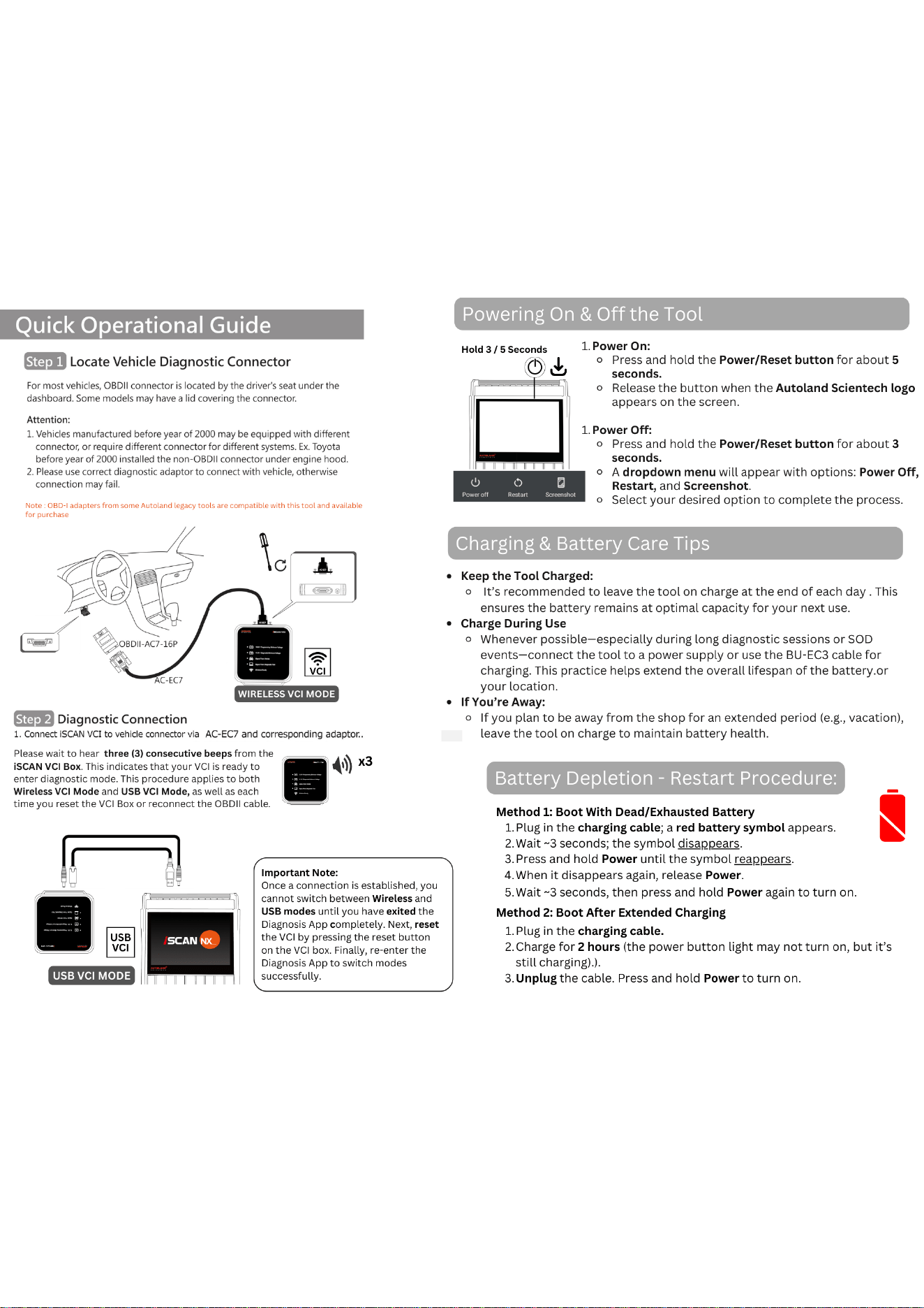
Step 1 Locate Vehicle Diagnostic Connector
for most vehicles, OBDll connector is located by the driver's seat under the
dashboard. Some models may have a lid covering the connector.
Attention:
1.Vehicles manufactured before year of 2000 may be equipped with different
connector or require dfferent connector for different systems.Ex Toyota
beforeyear of 2000 installed the non-OBDll connector under engine hood.
2.Please use correct diagnostic adaptor to connect with vehicle, otherwise
connection may fail.
Note 0DD-+acapters from someAutoland legacytoos are compatible with this tool and avaable
far purchase
2OBDII-AC7-16P
VCI
AC-EC7
WIRELESS VCI MODE
Step 2 Diagnostic Connection
1. Connect iSCAN VCI to vehide connector via AC-EC7 and corresponding adaptor..
Please wait to hear three(3) consecutive beeps from the
ISCAN VCI Box. This indicates that your VCI is ready to
enter diagnostic mode.This procedure applies to both
WirelessVCI Mode and USB VCI Mode,as well as each
time you reset the VCI Box or reconnect the OBDii able.
)
x3
Important Note:
Once aconnection is established,you
cannot switch between Wireless and
USB modes until you have exited the
Diagnosis App completely Next,reset
the VCI by pressing the reset button
on the VCI box.Finally, re-enter the
Diagnosis App to switch modes
successfully.
USB
VCi
SCAN NX
USB VCI MODE
Powering On&Off the Tool
Hold 3/5Seconds
1.Power On:
o Press and hold the Power/Reset button for about 5
seconds.
o Release the button when the Autoland Scientech logo
appears on the screen.
1.Power Off:
o Press and hold the Power/Reset button for about 3
seconds.
□
Paka a!
Betan
Sseshet
○ A dropdown menu will appear with options: Power Off,
Restart,and Screenshot.
o Select your desired option to complete the process.
Charging& Battery Care Tips
· Keep the Tool Charged:
o It's recommended to leave the tool on charge at the end of each day.This
ensures the battery remains at optimal capacity for your next use.
· Charge During Use
o Whenever possible-especially during long diagnostic sessions or SOD
events-connect the tool to a power supply or use the BU-EC3 cable for
charging.This practice helps extend the overallifespan of the battery.or
your location.
· IfYou're Away:
o Ifyou plan to be away from the shop for an extended period(e.g.,vacation),
leave the tool on charge to maintain battery health.
Battery Depletion-Restart Procedure:
Method 1:Boot With Dead/Exhausted Battery
1.Plug in the charging cable; a red battery symbol appears.
2.Wait  ̄3 seconds;the symbol disappears.
3.Press and hold Power until the symbol reappears.
4.When it disappears again, release Power.
5.Wait ̄3seconds, then press and hold Power again to turn on.
Method 2:Boot After Extended Charging
1.Plug in the charging cable.
2.Charge for 2 hours (the power button light may not turn on,but it's
still charging).).
3.Unplug the cable. Press and hold Powerto turn on.

FCC Warnning:
This equipment has been tested and found to comply with the limits for a Class B digital device,
pursuant to part 15 of the FCC Rules. These limits are designed to provide
reasonable
protection againstharmful interference in a residential installation. This equipment generates,
uses and can radiateradio
frequency
energy
and,
if
not
installed
and
used
in
accordance
with
the
instructions,
maycause
harmful
interference
to
radio
communications.
However,
there
is
no
guarantee
thatinterference
will
not
occur
in
a
particular
installation.
If
this
equipment
does
cause
harmfulinterference to radio or television reception, which can be
determined by turning the equipmentoff
and
on,
the
user
is
encouraged
to
try
to
correct
the
interference
by
one
or
more
of
thefollowing measures:
•
Reorient or relocate the receiving antenna.
•
Increase the separation between the equipment and receiver.
•
Connect the equipment into an outlet on a circuit different from that to which the receiver is
connected.
• Consult the dealer or an experienced radio/TV technician for help.
Caution:
Any
changes
or
modifications
to
this
device
not
explicitly
approved
by
manufacturer
could void your authority to operate this equipment.
This
device
complies
with
part
15
of
the
FCC
Rules.
Operation
is
subject
to
the
following
two
conditions:
(1)This
device
may
not
cause
harmful
interference,
and
(2)
this
device
must
accept
any
interference received, including interference that may cause undesired operation.
This
equipment
complies
with
FCC
radiation
exposure
limits
set
forth
for
an
uncontrolled
environment.
This
equipment
should
be
installed
and
operated
with
minimum
distance
20cm
between the radiator and your body.