User Manual
3 Product identification and positioning
3.1 production label
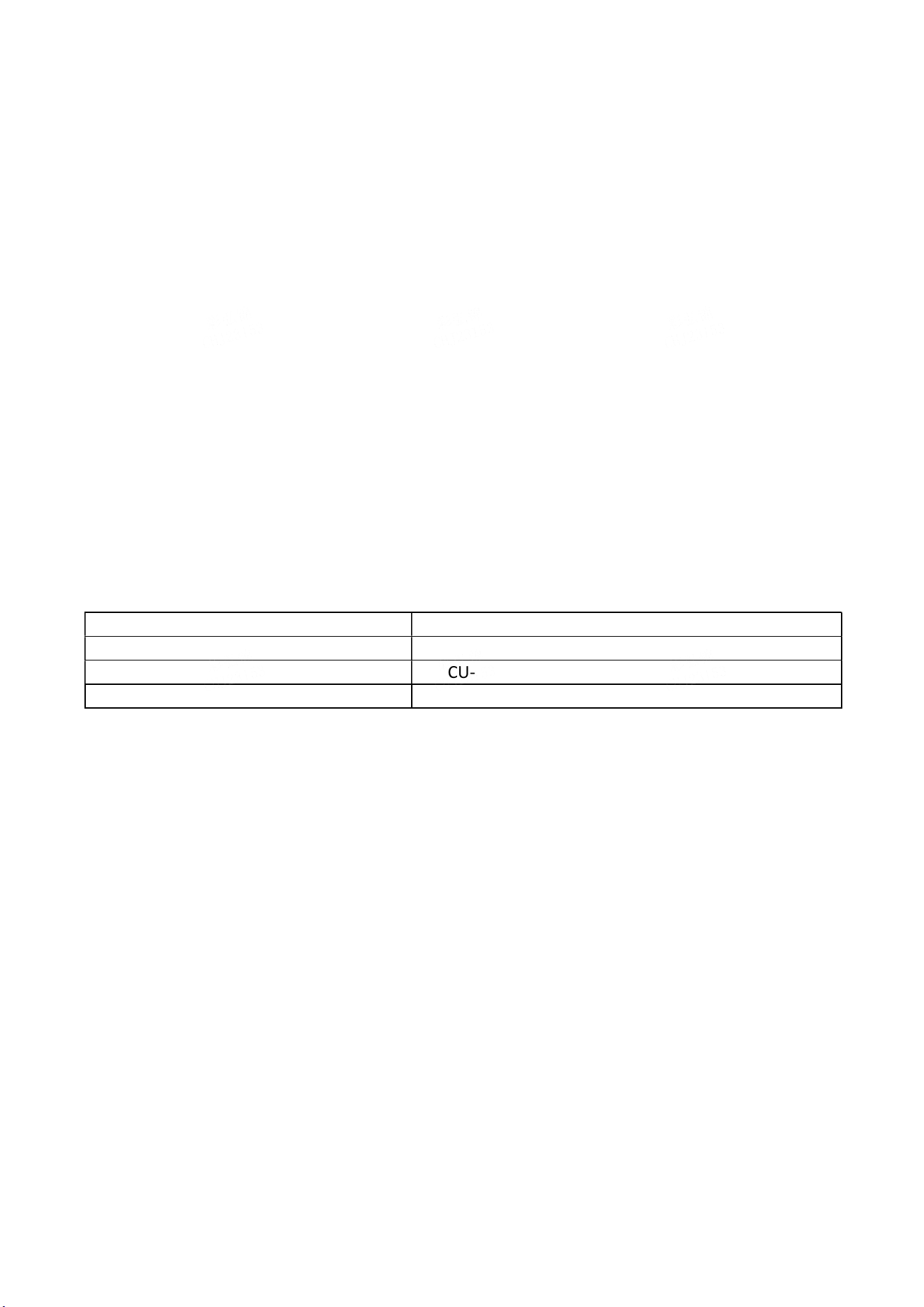
Identify the project Specific content
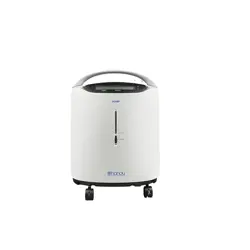
product name Type b concentrator
R&D code
JQ-DCU-EM32-B01
utility units Chongqing jiuqi science & technology company
3.2 Product positioning
Smart grid data acquisition core terminal equipment realizes centralized data acquisition, storage
and transmission of multiple power equipment of the same type, supports remote monitoring, fault
diagnosis and multi-protocol compatibility, and provides support for power remote monitoring,
billing and operation and maintenance management.
4 technical parameter
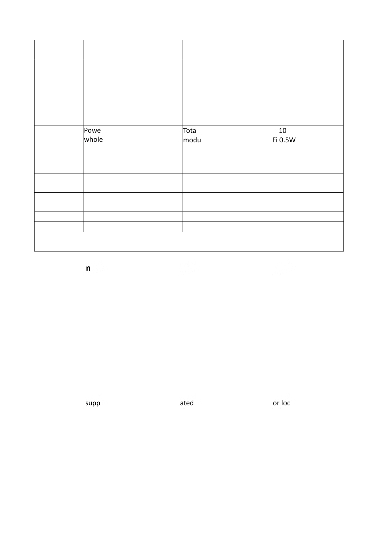
Parameter
category
specific items technical requirement
outline
dimension
Length, width and height
139*100*39±2mm
behaviour of
electricity
Power supply adaptability Only 24V input is supported in theory (it is not
recommended because of the risk of overheating,
and the manufacturer will not bear all the
responsibilities caused by it). Support 12V input
(recommended)
Power consumption of the
whole machine (double
network port scheme)
Total power consumption < <10W, MCU 0.5W, 4G
module 7.5W, Bluetooth +WiFi 0.5W, network
2.4W, other 2.2w.
Communication
performance
Support protocol
DL/T 645、Modbus RTU
Communication interface type
Ethernet (WAN/LAN dual-port), 4G, RS485,
Bluetooth
Operational
performance
Power-on start-up time of
equipment
≤30s
acclimatization
Working temperature
-20℃~+70℃
Storage temperature
-30℃~+80℃
Storage
performance
storage medium Internal Flash+external Flash dual media
5 Core function
5.1 Centralized acquisition of multi-equipment power data
● Acquisition object: multiple electric equipment of the same type (such as electric meters).
● Acquisition parameters: electric quantity, voltage and current;
● Access mode: RS485 interface and Ethernet (LAN port);
● Protocol adaptation:DL/T 645、Modbus RTU .
5.2 Data processing and storage
● Data preprocessing: check the validity of the collected data, filter the abnormal values and
make statistical analysis (hourly/daily/monthly statistical maximum, minimum and average);
● Data storage: internal Flash storage device configuration, short-term data within one week, and
cyclic coverage (permanent storage of key data) is supported;
● Data query: support the query request initiated by the superior platform or local debugging
terminal, and the response time is ≤1s.
5.3 Remote data transmission
● Transmission path: 4G wireless (supporting full netcom) and Ethernet (WAN port);
● Transmission protocol: MQTT;
● Transmission content: real-time collection of data, statistical data, equipment status data, fault
data and configuration response results;
● Transmission guarantee: automatic reconnection after disconnection, and supplementary
transmission of key data during interruption after reconnection.

5.4 Fault diagnosis and alarm
● Fault detection range:
. Hardware failure: abnormal power supply voltage, 4G module offline, Ethernet
disconnected, RS485 unresponsive, storage read-write error;
. Data failure: the collected data is missing, and the data is beyond the scope specified in the
agreemen;
. Protocol failure: 5 consecutive protocol frame parsing errors;
● Alarm mode:
. Local instructions: the power light (red) flashes (once per second, power failure), the 4G/
Ethernet light (green) goes out/flashes (twice per second, communication failure), and the
storage light (yellow) flashes (three times per second, storage failure);
. Remote reporting: fault type, fault code, occurrence time and duration;
5.5 Operation and maintenance and protocol configuration
● Remote upgrade: receive the upgrade package of the superior platform, back up the firmware
after MD5 verification, perform the upgrade, and automatically restore to the pre-upgrade
version after power failure;
● Protocol configuration: support superior platform or local debugging terminal to configure DL/T
645 (baud rate 2400/4800/9600bps) and Modbus RTU (slave station address, baud rate, parity
bit without/even);
● Local debugging: Connect the debugging terminal via Bluetooth, check the equipment status,
read the collected data and export the fault log;
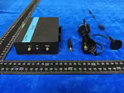
6 Hardware structure design
6.1 appearance design
Appearance structure: square iron box, standing, size (conventional design) length 139mm×
width 100mm× height 39mm;
Material technology: cold-rolled steel plate with 1mm shell, electrostatic spraying (black, RAL
9005); Front ABS plastic panel (white, RAL9003) with screen-printed interface logo;
Installation method: wall-mounted (2 installation holes on the back, with a diameter of Φ 5 mm
and a spacing of 150mm), supporting desktop/cabinet placement;
6.2 Interface layout
● Top: 2 antenna interfaces (4G/ Bluetooth +WiFi antenna);
● Front: 2 RJ45 Ethernet ports (marked "WAN" and "LAN"), RS485 interface (marked "5GND BA"),
5 status indicators (power supply, BLE/WIFI, 4G, NET, ERR) and 1 DC jack.;。
6.3 Hardware architecture (dual-port scheme)
kernel module functional description
MCU module Core control, data scheduling, protocol analysis, task management.
4G module 4G wireless communication, supporting full netcom
Bluetooth +WiFi module 5.0 Local debugging, supporting Bluetooth 5.0.
network module 100 Gigabit Ethernet, WAN port (platform communication), LAN
port (equipment acquisition)
power-supply module 220V AC to DC, output 3.3V(MCU/ Bluetooth +WiFi), 5V. (network
module), 12V(4G module)
Detection module Voltage/current detection, communication status detection, fault
location to module level.
7 Software architecture design
7.1 Software layered architecture
Software hierarchy Core function
Hardware driver layer GPIO/UART/SPI/IIC/EMAC driver and communication module (4G/
Ethernet /RS485/ Bluetooth) driver and external storage (SPI-Flash)
driver.
Operating system layer Real-time task scheduling (preemptive priority), memory
management (dynamic allocation /release), interrupt management,
IPC (semaphore/message queue)
Middleware layer MQTT protocol stack, TCP/IP protocol stack (LwIP), FAT32 file
system, Log management and firmware upgrade module
application layer Protocol analysis (DL/T 645/Modbus RTU), data acquisition, data
Processing, MQTT transmission, fault alarm, configuration
management
7.2 Software workflow
1. Initialization: hardware self-check (power supply/communicaon/storage) → soware loading
(operang system/middleware/applicaon task) → local alarm will be triggered if the self-check
is abnormal;
2. Data interaction:
○ Data reporting: collecting terminal data → preprocessing →MQTT encapsulaon →4G/
Ethernet uploading;
○ Task receiving: receiving the file/collecon tasks distributed by the plaorm → analyzing
and execung → feeding back the execuon results;
3. Fault handling: real-time monitoring of hardware/data/protocol status → fault triggering alarm
(local+remote) → automac recovery aempt (such as network reconnecon) → report "fault
removal" after recovery.
8 Reliability guarantee
8.1 Environmental adaptability
● High and low temperature tolerance: the core components (boards and components) can work
at-20℃ ~+70℃ and store at-30℃ ~+80℃;
● Anti-vibration and impact: structural reinforcement (frame/case reinforcement), anti-loosening
of components (pin welding reinforcement), and adaptation to vibration and impact during
transportation/use;
● Electromagnetic compatibility: EMI filter (lead ≤ 5 cm) is connected in series at the power inlet;
The power supply layer of PCB is close to the stratum, and the digital/analog circuits are
arranged separately (spacing ≥ 2mm); The laying distance of DC power line/signal line is
≥10mm;

8.2 Safety protection design
● Electrical safety: grounding nearby (grounding resistance ≤ 4Ω); The cross-sectional area of the
power cord is 1.5mm² (meet the maximum load), and the width of the printed wire is ≥1mm
(current ≥1A);
● Anti-insertion design: the models of power socket (word) and signal socket (RJ45/ terminal
block) are different; Screen-printed error-proof marks for similar parts (such as terminal blocks);
● Mechanical safety: the shell has no sharp corners (chamfering R2mm), and the corners of
internal reinforced structural members are treated with circular arcs (R3mm); Parts screw
fastening (torque 0.8-1.2 nm);
8.3 Operation and maintenance support
● Visual status: 5 indicator lights visually display the running status of the equipment;
● Fault location: the detection module locates the fault to the module level, and records the fault
details in the log;
● Remote operation and maintenance: support remote upgrade and configuration of 4G/
Ethernet, and reduce on-site operation;
9 supplementary provisions
1. The right to interpret this specification belongs to Chongqing Jiuqi Technology Company;

FCC Statement
This equipment has been tested and found to comply with the limits for a Class
B digital device, pursuant to part 15 of the FCC rules. These limits are
designed to provide reasonable protection against harmful interference in a
residential installation. This equipment generates, uses and can radiate radio
frequency energy and, if not installed and used in accordance with the
instructions, may cause harmful interference to radio communications.
However, there is no guarantee that interference will not occur in a particular
installation. If this equipment does cause harmful interference to radio or
television reception, which can be determined by turning the equipment off and
on, the user is encouraged to try to correct the interference by one or more of
the following measures:
-
Reorient or relocate the receiving antenna.
-Increase the separation between the equipment and receiver.
-Connect the equipment into an outlet on a circuit different from that to which
the receiver is connected.
-Consult the dealer or an experienced radio/TV technician for help.
To assure continued compliance, any changes or modifications not expressly
approved by the party.
Responsible for compliance could void the user’s authority to operate this
equipment. (Example- use only shielded interface cables when connecting to
computer or peripheral devices).
Any Changes or modifications not expressly approved by the party responsible
for compliance could void the user's authority to operate the equipment.
This equipment complies with Part 15 of the FCC Rules. Operation is subject
to the following two conditions:
(1) This device may not cause harmful interference, and
(2) This device must accept any interference received, including interference
that may cause undesired operation.
FCC Radiation Exposure Statement:
The equipment complies with FCC Radiation exposure limits set forth for
unc
ontrolled enviroment. This equipment should be installed and operated with
minimum distance 20cm between the radiator and your body.