IL1576
1
SELECTRONIC
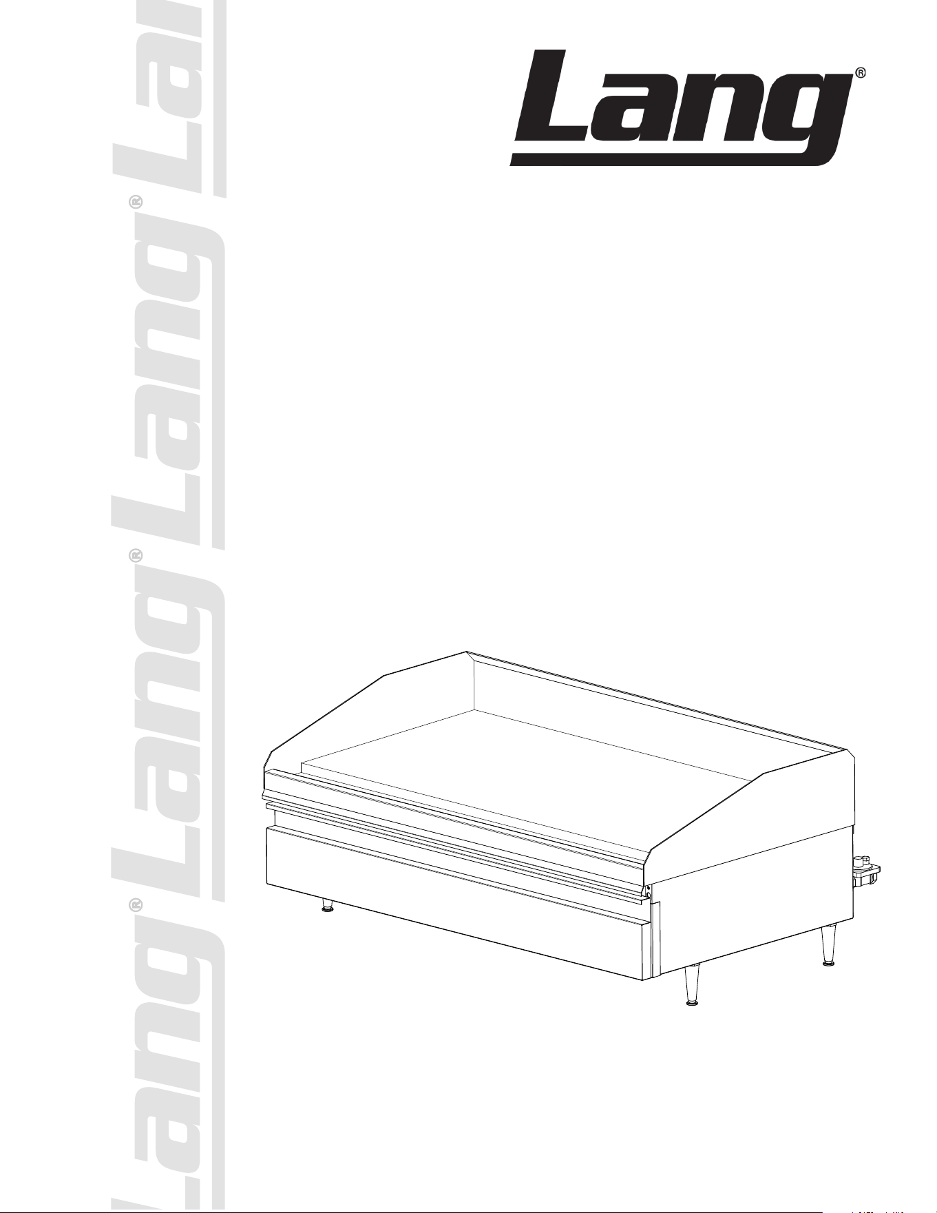
GAS GRIDDLE
Commercial
224S, 224SC, 224SHE, 224SCHG
236S, 236SC 236SCHG, 236SHE, 236SHG
248S, 248SHE, 248SHG, 260S, 272S
Installation and
Operation
Instructions
2M-W360 REV P (01-25)
248S
2
SAFETY SYMBOL
Model No.:
Serial No.:
Voltage:
1-Phase or 3 Phase:
Purchased From:
Location:
Purchase Date:
Installed Date:
These symbols are intended to alert the user to the presence of important operating
and maintenance instructions in the manual accompanying the appliance.
FOR YOUR SAFTEY
DO NOT STORE OR USE GASOLINE OR OTHER FLAMMABLE VAPORS AND LIQUIDS IN
THE VICINTIY OF THIS OR ANY OTHER APPLIANCE.
The installation of the Appliance must conform to the NATIONAL FUEL GAS CODE "ANSI Z223.1 - LATEST
EDITION" AND ALL LOCAL GAS COMPANY RULES AND REGULATIONS.
IN CANADA INSTALLATION SHALL BE IN ACCORDANCE WITH THE CURRENT CAN/CGA-B149.1 NATURAL
GAS INSTALLATION CODE OR CAN/CGA-B149.2 PROPANE INSTALLATION CODE AND LOCAL CODES WHERE
APPLICABLE.
POST IN PROMINENT LOCATION
INSTRUCTIONS TO BE FOLLOWED IN THE EVENT USER SMELLS GAS. THIS INFORMATION
SHALL BE OBTAINED BY CONSULTING YOUR LOCAL GAS SUPPLIER. AS A MINIMUM, TURN
OFF THE GAS AND CALL YOUR GAS COMPANY AND YOUR AUTHORIZED SERVICE AGENT.
EVACUATE ALL PERSONNEL FROM THE AREA.
WARNING
IMPROPER INSTALLATION, ADJUSTMENT, ALTERATION, SERVICE OR MAINTENANCE CAN
CAUSE PROPERTY DAMAGE, INJURY OR DEATH. READ THE INSTALLATION, OPERATION
& MAINTENANCE INSTRUCTIONS THOROUGHLY BEFORE INSTALLING OR SERVICING THIS
EQUIPMENT.
WARNING
RISK OF FIRE OR ELECTRIC SHOCK
DO NOT OPEN
WARNING, TO REDUCE THE RISK OF ELECTRICAL SHOCK, DO NOT REMOVE
CONTROL PANEL. NO USER-SERVICABLE PARTS INSIDE.
REPAIRS SHOULD BE DONE BY AUTHORIZED SERVICE PERSONNEL ONLY.
NOTICE
Using any part other than genuine Lang factory supplied parts relieves the manufacturer of all liability.
Lang reserves the right to change speci cations and product design without notice. Such
revisions do not entitle the buyer to corresponding changes, improvements, additions or
replacements for previously purchased equipment.
Due to periodic changes in designs, methods, procedures, policies and regulations, the
specifications contained in this sheet are subject to change without notice. While Lang
Manufacturing exercises good faith efforts to provide information that is accurate, we are
not responsible for errors or omissions in information provided or conclusions reached as a
result of using the speci cations. By using the information provided, the user assumes all risks in con-
nection with such use.
MAINTENANCE AND REPAIRS
Contact your local dealer for service or required maintenance. Please record the model number, serial
number, voltage and purchase & Installation Information in the area below and have it ready when you
call to ensure a faster service.

3
TABLE OF CONTENTS
Specications 4 - 5
Equipment Description 6
Unpacking 7
Installation
Ventilation & Clearance 7
Electrical & Gas Connection 8
Initial Start-Up
Initial Lighting Procedure 9
Seasoning Cooking Surface 9
Operation
Setting the Griddle Temperature 10
Suggested Times and Temperatures 10
Loading the Griddle 11
Sequence of Operation
Power On 12
Maintenance
Daily Cleaning 13
Weekly Cleaning 13
Burner Air Shutter Adjustment 13
Troubleshooting
Symptoms / Possible Causes 14
Possible Causes / Test 15
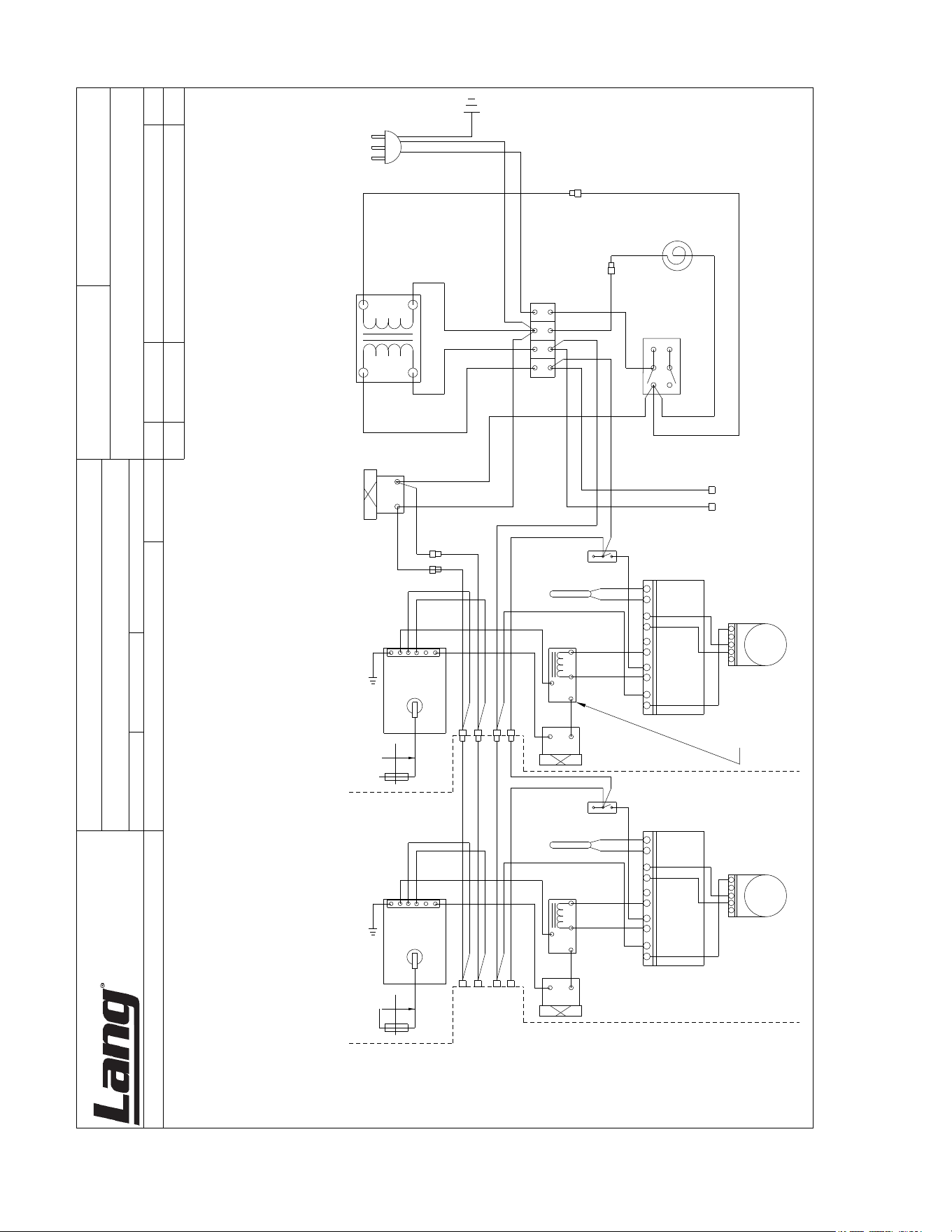
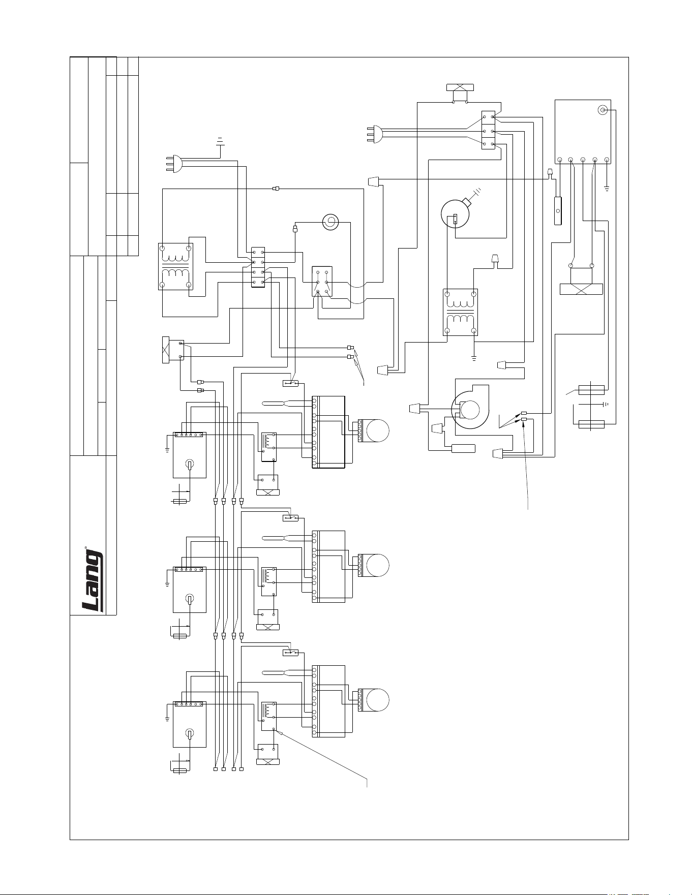
Wiring Diagram 16
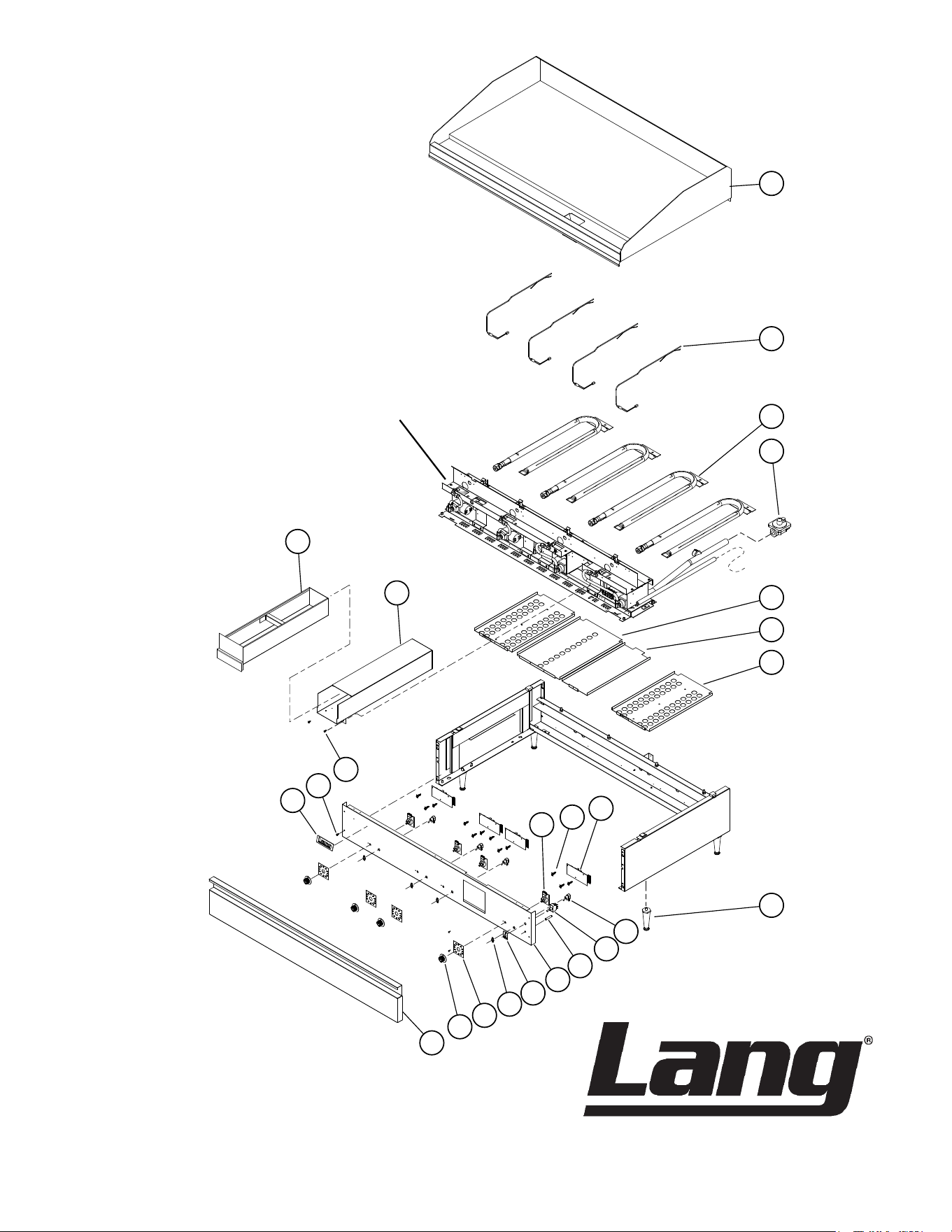
Exploded View & Parts List 20-26
Warranty 27
PROBLEMS, QUESTIONS or CONCERNS
Before you proceed consult you authorized Lang service agent directory
or
Call the Lang Technical Service & Parts Department at 800-264-7827
NOTICE ServiceonthisoranyotherLangappliancemustbeperformedbyqualied
personnel only. Consult your Lang Authorized Service Agent Directory.
You can call our tech service number 800-264-7827 or visit our website
WWW.LANGWORLD.COM for the service agent nearest you.
4
16.4”
4.0”
20.4”
30.4”
W”
Top
Front Side
IL1577
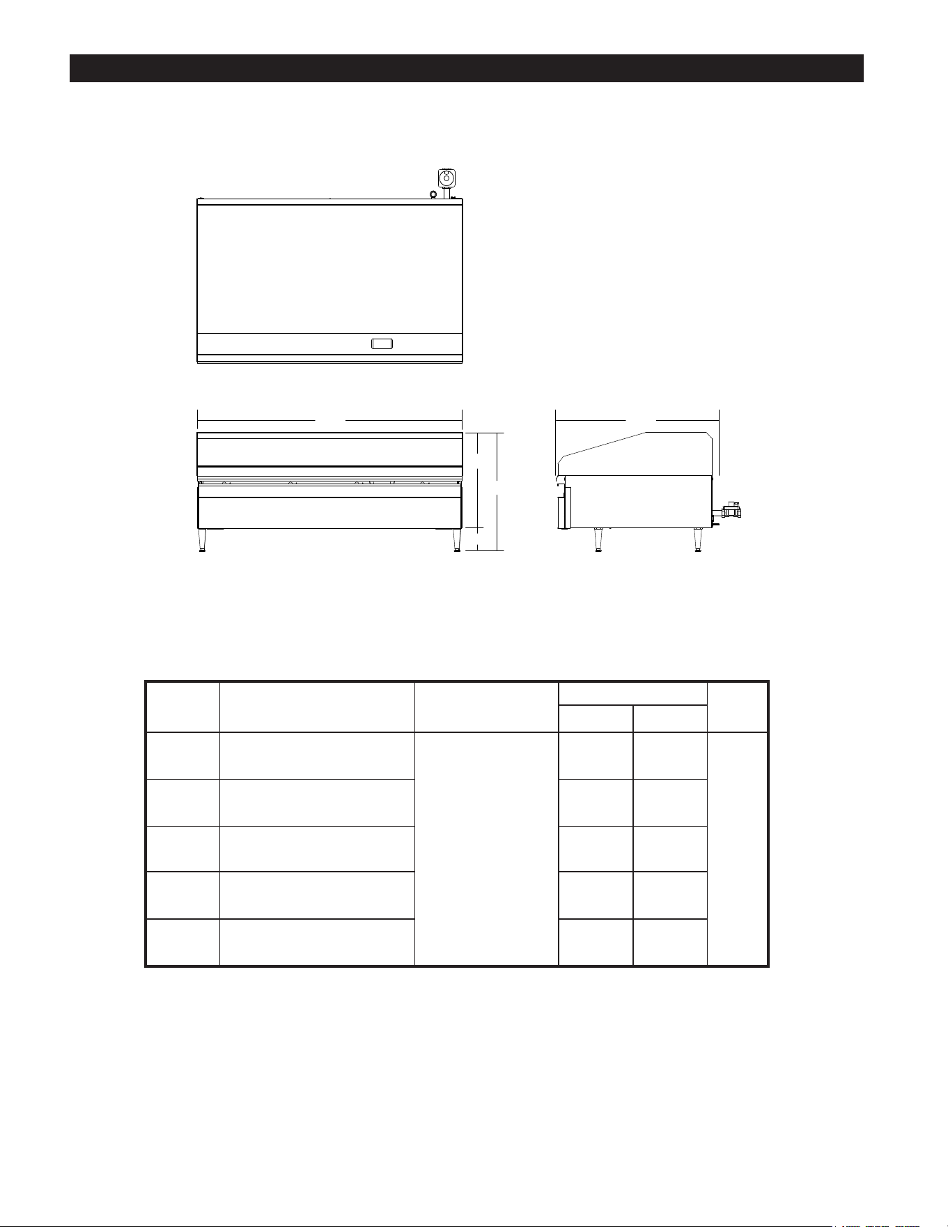
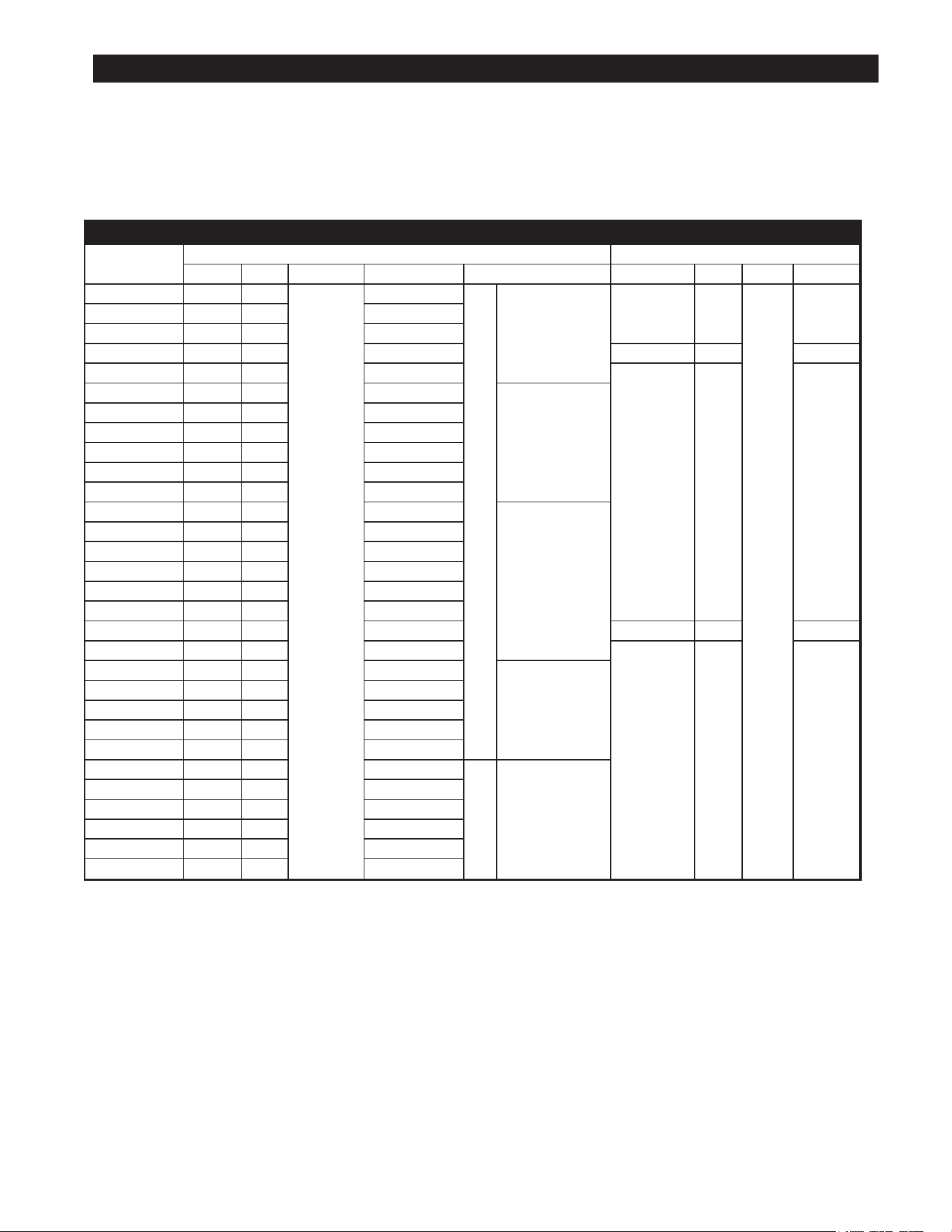
EQUIPMENT SPECIFICATIONS
Model
Height x Width x Depth Clearance from Weight
Freight
Class(Not including legs) combustible surface Actual Shipping
224S
16.4” x 24.1” x 30.4” 243 lbs. 280 lbs.
65
418mm x 613mm x 773mm 110 kg 127 kg
236S
16.4” x 36.1” x 30.4” 368 lbs. 420 lbs.
418mm x 917mm x 773mm 167 kg 191 kg
248S
16.4” x 48.1” x 30.4” Sides: 5” 448 lbs. 520 lbs.
418mm x 1222mm x 773mm Back: 5” 204 kg 236 kg
260S
16.4” x 60.1” x 30.4” 556 lbs. 635 lbs.
418mm x 1527mm x 773mm 253 kg 289 kg
272S
16.4” x 72.1” x 30.4” 689 lbs. 800 lbs.
418mm x 1832mm x 773mm 313 kg 364 kg
5
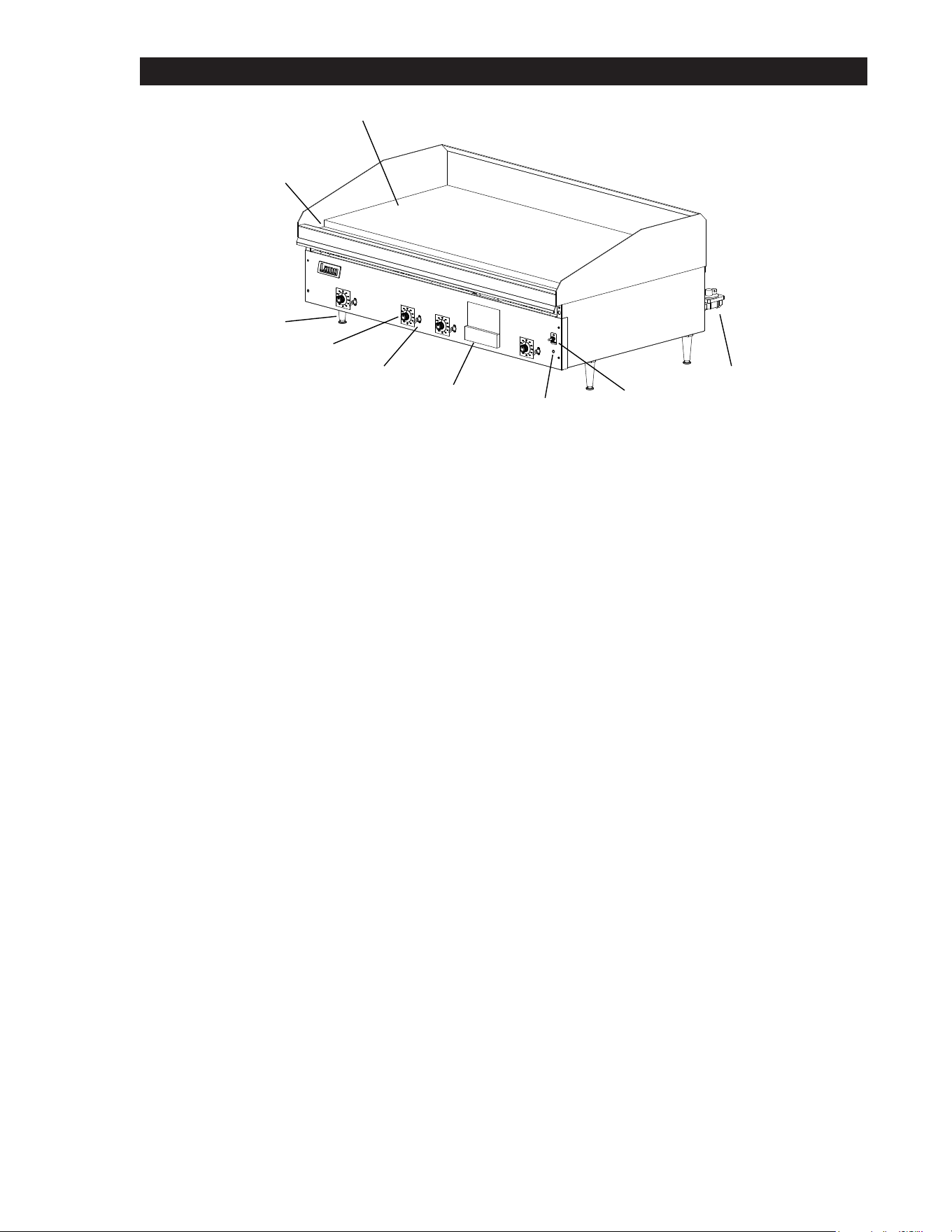
EQUIPMENT SPECIFICATIONS
SPECIFICATIONS
Current Model
Gas Requirements Electrical Requirements
NAT.Gas LP. Gas Burner Input Manifold Press. Gas Connection (3/4” NPT) Voltage Total kW Phase Amps /Line
224S-NAT X
27,000
5 WC
1
50,000 BTU/hr
115V/60Hz 0.5
1
2.0224SC-NAT X 5 WC
224SHE-NAT X 5 WC
224SR-LP X 10 WC 240V/60Hz 0.25 1.0
224SR-NAT X 5 WC
115V/60Hz 0.5 2.0
236SC-NAT X 5 WC
81,000 BTU/hr
236SCHG-NAT X 5 WC
236SHE-NAT X 5 WC
236SHG-NAT X 5 WC
236S-LP X 10 WC
236S-NAT X 5 WC
248SHG-NAT X 5 WC
108,000 BTU/hr
248SHG-LP X 10 WC
248SHE-NAT X 5 WC
248S-LP X 10 WC
248S-NAT X 5 WC
248S-NATSC X 5 WC
248SR-LP X 10 WC 240V/60Hz 0.25 1.0
248SR-NAT X 5 WC
115V/60Hz 0.5 2.0
260S-LP X 10 WC
135,000 BTU/hr
260S-NAT X 5 WC
260SC-NAT X 5 WC
260S-NATSC X 5 WC
260SCHE-NAT X 5 WC
272S-LP X 10 WC
2 162,000 BTU/hr
272S-NAT X 5 WC
272S-NATSC X 5 WC
272SB-NAT X 5 WC
272SHE-NAT X 5 WC
272SHG-NAT X 5 WC
6
EQUIPMENT DESCRIPTION
Exterior Construction
The griddle dimensions are 17” (43.18cm) High, 30” (76.20cm) Deep, and width is dependent on the
actual model number.
The Sides, Bottom, and Rear wall are constructed of double wall stainless steel, which allows closer
installation to combustible surfaces.
The stainless steel drop-down door keeps the controls cool and control area clean.
The griddle surface is made of 1” thick, highly polished steel to reduce hot and cold spots, recovery
problems, warping, and ensure even heat to the edges of the griddle.
Controls
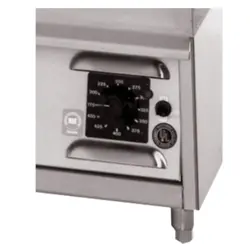
The Selectronic Griddle comes with the solid state controls which include:
• A Main Power Switch & Power Indicator for the entire unit.
• Each twelve-inch section has its own temperature selector switch that snaps into place to lock in
any temperature from 175°F to 450°F (79°C to 232°C) in 25° increments.
• Each twelve-inch section of the griddle is controlled by an area sensitive RTD probe, which can
sense and react to a temperature change of +/- 4°F.
Technical
• Griddle operates on either Natural gas or Propane. This must be specied when ordering. It is
shipped with a Power Cord and Plug attached.
• Floor space required is 30” (76.20cm) Deep, and width is 2 ft, 3ft, 4ft, 5ft, or 6ft depending on actual
model number.
• The griddle weighs 260, 390, 520, 650, 780 lbs. depending on actual model number.
GriddleGasandVoltageSpecications
The Lang Model can be connected to any 120 Volt source. The gas and electrical specications are
listed in the table on the previous page.
NOTICE The data plate is on the right side of the griddle. The oven voltage,
wattage,serialnumber,wiresize,andclearancespecicationsare
on the data plate. This information should be carefully read and
understood before proceeding with the installation.
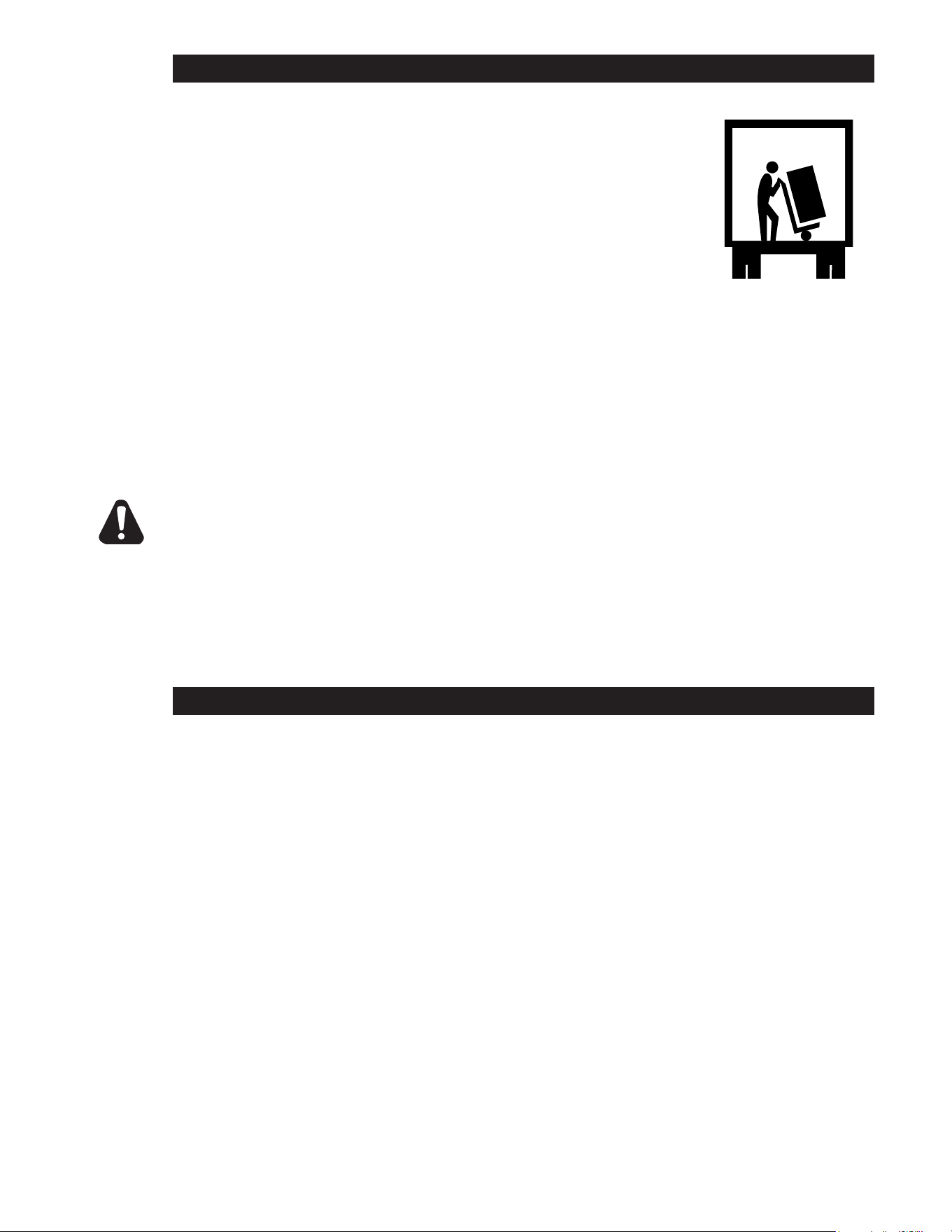
IL1575
1” Griddle Surface
Gutter
Legs
Grease
Pan
Power
Indicator
Main
Power
Switch
Gas
Regulator
Section
Temp. Dial
Section
Power Switch
Panel Cover Removed for Clarity
7
UNPACKING
Receiving the Griddle
Upon receipt, check for freight damage, both visible and concealed.
Visible damage should be noted on the freight bill at the time of delivery and
signed by the carrier’s agent. Concealed loss or damage means it does not
become apparent until the merchandise has been unpacked. If concealed
loss or damage is discovered upon unpacking, make a written request for
inspection by the carrier’s agent within 15 days of delivery. All packing
material should be kept for inspection. Do not return damaged
merchandise to Star Manufacturing Company. File your claim with the
carrier.
Location
Prior to un-crating, move the oven as near to its intended location as practical. The crating will help
protect the unit from the physical damage normally associated with moving it through hallways and
doorways.
Un-crating
The griddle will arrive completely assembled inside a wood frame and strapped to a skid.
Cut the straps and remove the wood frame.
The oven can now be removed from the skid.
THE UNIT IS EXTREMELY HEAVY. FOR SAFE HANDLING, INSTALLER
SHOULD OBTAIN HELP AS NEEDED, OR EMPLOY APPROPRIATE MATERIALS
HANDLING EQUIPMENT (SUCH AS A FORKLIFT, DOLLY, OR PALLET JACK)
TO REMOVE THE UNIT FROM THE SKID AND MOVE IT TO THE PLACE OF
INSTALLATION.
ANY STAND, COUNTER OR OTHER DEVICE ON WHICH OVEN WILL BE
LOCATED MUST BE DESIGNED TO SUPPORT THE WEIGHT OF THE GRIDDLE.
SHIPPING STRAPS ARE UNDER TENSION AND CAN SNAP BACK WHEN CUT.
VENTILATION & CLEARANCE
CLEARANCE
For use on non-combustible countertops only.
Combustible and non-combustible material must be at least 48” (120cm) from the top of the
appliance and 5” (150mm) from the sides and back. Adequate clearance should also be provided
for proper operation and servicing.
AIR SUPPLY
Make certain not to obstruct the ow of combustion and ventilation air. Provisions for adequate air
supply must be furnished. The legs supplied with the unit must be installed. Make certain that air
intake openings in the bottom of the appliance are not obstructed. They are essential for proper
combustion and operation of the appliance.
EXHAUST CANOPY
It is essential that facilities be provided over the griddle to carry o fumes and gases. However,
the unit should not be directly connected to a ue or stack.
CAUTION

8
INSTALLATION
Electrical Connection
The 120V griddles are supplied with a cord and plug, 240V units are not. The 120V receptacle is not
provided with the griddle.
Follow the receptacle manufacturer’s instructions when connecting the receptacle to the power supply.
Gas Connection
This griddle is manufactured for use with the type of gas indicted on the nameplate.
Contact the factory if your type of gas does not match the nameplate data.
All gas connectors must be in accordance with local codes and comply with the National Fuel Federal
Gas Codes ANSI Z223.1 latest edition.
This appliance should be installed with a separate gas valve in the gas line ahead of the unit. Use a
3/4 inch or larger gas supply line.
Remove the 5/16 inch nuts securing the rear of burners. These nuts are for securing the main burners
during transportation only. The rear burner shield must be removed to gain access to the nuts.
A pressure regulator for the type of gas specied is supplied with each appliance.
This regulator must be installed in the gas supply line. (Note the direction of the gas ow arrow.)
The pressure in the manifold of the appliance should be tested with a manometer and the regulator
adjusted for proper pressure with the appliance operating at full re. A 1/8 inch NPT tap is provided in
the manifold for connecting a manometer.
Correct manifold pressures are:
5 inches water column for natural gas
10 inches water column for propane
When replacing the plug in the manifold, a pipe joint compound or sealant should be used that is
resistant to the action of liquid petroleum gas.
Initial adjustments are the responsibility of the installer and are not chargeable to Star Manufacturing
International.
After the griddle is in its nal position, adjust the legs to create 1/8 inch slant from back to front.
This will allow the grease to run into the grease gutter and provide the proper combustion air for the
burners.
DANGER: THIS APPLIANCE MUST BE GROUNDED AT THE TERMINAL
PROVIDED. FAILURE TO GROUND THE APPLIANCE COULD
RESULT IN ELECTROCUTION AND DEATH.
INSTALLATION OF THE UNIT MUST BE DONE BY PERSONNEL
QUALIFIED TO WORK WITH ELECTRICITY AND PLUMBING.
IMPROPER INSTALLATION CAN CAUSE INJURY TO PERSONNEL
AND/OR DAMAGE TO EQUIPMENT. UNIT MUST BE INSTALLED IN
ACCORDANCE WITH ALL APPLICABLE CODES.
NOTICE: The data plate is located inside the control compartment of each
griddle.Thegriddlevoltage,serialnumber,gasspecications,and
clearancespecicationsareonthedataplate.Thisinformation
should be carefully read and understood before proceeding with
the installation.
NOTICE: The installation of any components such as a vent hood, grease
extractors,reextinguishersystems,mustconformtotheir
applicable National, State and locally recognized installation
standards.
WARNING

9
INITIAL START UP
Initial Lighting Procedure
Clean the preservative coating from the griddle plate and splash guard. Add a mild detergent to hot
water and wash the griddle plate and splash guard. Rinse with a damp sponge and dry with a clean
rag.
WARNING: BEFORE LIGHTING, USE A SOAP AND WATER SOLUTION TO
TEST ALL JOINTS FOR GAS LEAKS.
• Plug the unit into a power supply that matches what is listed on the nameplate.
• Turn the ON-STANDBY toggle switch to ON.
• Set the temperature dials to the desired temperature.
• Turn the toggle switch to each section to ON.
• To turn the griddle o, simply turn the main toggle switch to STANDBY.
Seasoning the Griddle Plate (non chrome only)
• Set the temperature dials to 300°F (148°C).
• Observe the burners through the opening at the top of the control panel.
• When the burners go OFF, apply a thin coat of high-grade, non-salted vegetable oil to the
griddle surface.
• Rub the oil into the griddle surface with the at side of a spatula or a towel.
• Recoat any dry spots that appear then wait two minutes and wipe o any excess oil.
• Repeat the seasoning process at 350°F (176°C) and at 400°F (204°C).
NOTICE: Duringtherstfewhoursofoperationyoumaynoticeasmall
amountofsmokecomingothegriddle,andafaintodorfrom
the smoke. This is normal for a new griddle and will disappear
aftertherstfewhoursofuse.
10
OPERATION
Setting the Griddle Temperature
The suggested time and temperature chart (below) is provided as a guide for the products listed only.
If dierent temperature settings are to be used, select one side of the griddle and operate at the lowest
temperature. Adjoining sections should be set at progressively higher temperatures.
Do not try to operate the end sections hot and the center sections cool.
ALWAYS KEEP THE AREA NEAR THE APPLIANCE FREE FROM
COMBUSTIBLE MATERIALS.
KEEP FLOOR IN FRONT OF EQUIPMENT CLEAN AND DRY. IF
SPILLS OCCUR, CLEAN IMMEDIATELY, TO AVOID THE DANGER
OF SLIPS OR FALLS.
CAUTION
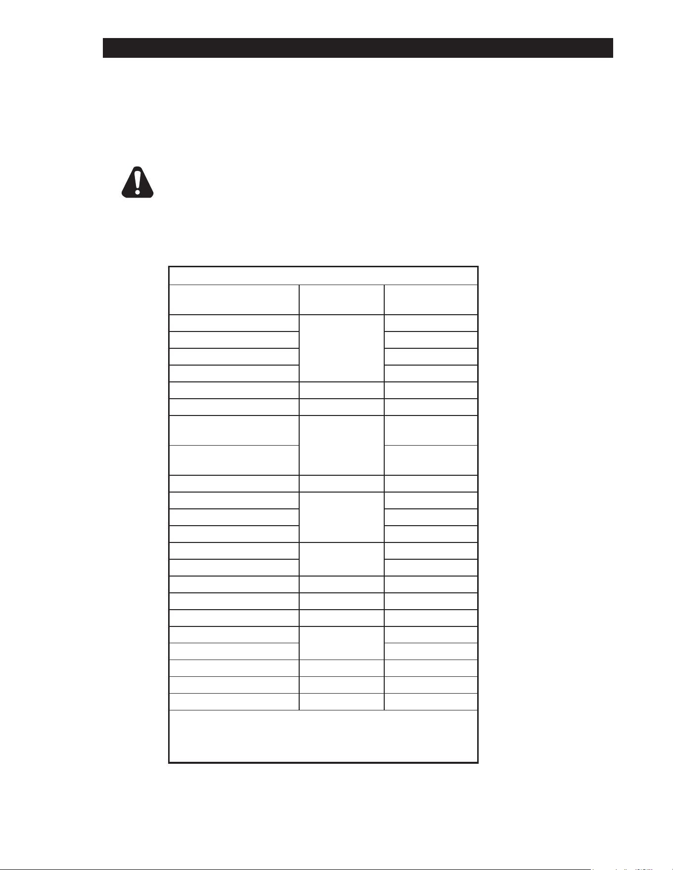
SUGGESTED TIMES AND TEMPERATURES
PRODUCTS
TEMPERATURE
(F / C) TIME (MIN)
HAMBURGER
350°F (176°C)
2 patties per LB 6 to 8
4 patties per LB 4 to 6
6 patties per LB 3 to 4
STEAKS
1/2 to 3/4 inch thick, cooked
medium
375°F (190°C)
5 to 7
3/4 to 1 inch thick, cooked
medium 8 to 10
Lamb Chops
350°F (176°C)
6 to 8
Pork Chops 6 to 8
Salmon 6 to 8
Halibut
325°F (162°C)
6 to 8
Snapper 6 to 8
Hashbrown Potatoes 375°F (190°C) 3 to 4
Bacon
350°F (176°C)
3 to 4
Sausage Links or Patties 3 to 4
Ham (Pre-cooked) 375°F (190°C) 2
Eggs 275°F (135°C) 2 to 4
Note: The times and temperatures in this chart are intended as a general
guide and starting point. Your actual times and temperatures may vary from
this chart.

11
OPERATION
Loading the Griddle
An understanding of how the griddle sections are controlled will be a valuable aid in loading your
griddle.
Each 12 inch section of your griddle is independently controlled. The temperature control sensor is
mounted under the griddle plate in the center of each cooking section.
If the product is loaded directly over the temperature sensor, that section will turn on and the
burner will heat the entire cooking section. If the product is loaded to the side, front or back of the
temperature sensor, the thermostat will react to the temperature change much slowly.
During slow periods with minimal loads, do not load directly over the thermostat sensors as this will
unnecessarily turn the burners on and overheat the remainder of the section not being utilized.
Turn the product and continue cooking until it has reached its desired degree of doneness.
Remove the product from the griddle.
When reloading the griddle, rst use the griddle surface on which a previous load was not placed.
This will insure you the proper griddle temperature.

12
SEQUENCE OF OPERATION
Power On
When the griddle is connected to 115 Volt power, the spark module for each section starts sparking.
While they are sparking the solenoid valve for the pilot burners are energized.
When the individual pilot burners ignite, and the pilot ame is veried, the spark module will stop
sparking. Note: The pilot burners will remain lit until the griddle is removed from power or the gas is
shut o.
When the main switch is turned on, 24 Volts is applied to the temperature control circuit.
When one of the individual section’s switch is turned on, it provides power to the circuit board for that
section.
The operator can now set the temperature of that section by selecting it on the temperature dial.
When the temperature on the dial is set higher than the temperature of the griddle section the circuit
board will generate a “Heat call”. This call (24 VAC Signal) goes to the solenoid valve opening the
valve. The pilot burner ignites the main burner.
As the griddle section temperature increases the temperature sense probe resistance increases.
When the griddle section reaches the temperature set on the selector switch, the circuit board which
monitors the probe resistance will turn o the heat call and there by close the gas valve.
When the griddle temperature drops below the set temperature the circuit board generates a new
heat call and the sequence repeats.
MAINTENANCE & CLEANING
Griddle Care (Chromium Surfaces)
It takes very little time and eort to keep this Industrial Chromium griddle surface sparkling clean and
performing at top eciency. DO NOT allow grease to accumulate as it will carbonize and become
dicult to remove. To prevent this condition the following cleaning suggestions should be followed:
1. Remove excess grease and food regularly with a 4” (100mm) wide Razor Sharp type scraper
and wipe surface with a damp cloth if desired.
2. Following the scraping, for end of the day cleaning, a damp cloth and a non-silicated,
nonabrasive, non-chlorinated cleaner such as Bon-Ami may be used to wipe surface clean,
followed by wiping with a clean wet cloth.
3. Follow steps 2 and 3 from Griddle Care (Non-Chromium Surfaces) above.
CAUTION
1 Never use pumice, griddle stones, or abrasives on a chromium surface.
2 Never strike a chromium griddle surface with a sharp instrument or spatula edge.
3 Never use steel wool.
4 Never use commercial liquid grill cleaner on the griddle surface.
5 Abusing surface voids the warranty.
CHROME GRIDDLE SURFACE LIMITED WARRANTY EXCLUSIONS
Your Chrome griddle has been designed to give you many years of cooking reliability and requires
minimum maintenance to keep the chrome surface in its original condition. All Chrome griddle
surfaces are warranted for a period of 5 years against manufacturing defects to the original owner
from the date of installation. This limited warranty is void if it is determined by Lang Manufacturing
or one of its authorized representatives that the chrome surface has been misused or abused or
subjected to the following situations:
1. Improperly installed.
2. Incorrect voltage applied to Chrome units allowing the surface to overheat and discolor.
3. The misuse of any instrument or tool which scratches or makes indentations in the surface which
could cause the surface to peel, ake, or chip o.
4. The use of any chemical or abrasive cleaning solution, griddle brick, stone, screen or other
cleaning products which could damage and aect the performance of the chrome surface.
5. The neglect of daily routine maintenance to the chromium surface.
13
MAINTENANCE & CLEANING continued
Daily Cleaning (Non chrome only)
• Empty the grease drawer daily or whenever it is 3/4 full. It is easily removed for washing.
• Keep the griddle surface clean. After each cooking load, scrape the griddle surface to remove any
carbonized grease.
• Once a day or when necessary the non chrome griddle surface should be thoroughly cleaned and
seasoned again. Use a griddle stone, griddle pad, or liquid cleaner. Rub with the grain of the
metal, being careful not to scrape the splash guard.
• Chrome griddle surfaces can be scraped with a 4” wide Razor Sharp scrapper and wipe surface
with a damp cloth.
• Following the scraping, a damp cloth and non-silicated, non-abrasive, non-chlorinated cleaner such
as Bon-Ami may be used to wipe surface clean, followed by wiping with a clean wet cloth.
Weekly Cleaning (Non chrome only)
• A mild detergent with water or one of the many commercial cleaners may be used.
• Be sure to rinse thoroughly and coat the griddle with a thin lm of oil to prevent rusting,
non-chrome surfaces only.
• Clean the exterior of the appliance with hot water and a mild detergent to maintain a gleaming
appearance.
• Re-season the griddle plate after each cleaning, non-chrome surfaces only.
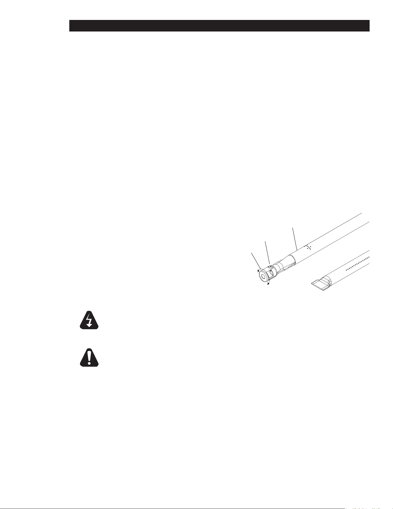
Burner Air Shutter Adjustment
• The air shutters are pre-set at the factory.
However, minor adjustments may be required in
the eld to accommodate dierences in gas and
elevation.
• To adjust the air shutters, loosen the set screw
holding the air damper to the burner near the gas
inlet.
• Adjust the air mixture until the burner ame just
ickers on the burner. “Lift-o” or yellow ame
indicates improper shutter adjustment.
• Periodically inspect and clean the air shutters to
insure complete combustion.
WARNING: KEEP WATER AND SOLUTIONS OUT OF CONTROLS. NEVER SPRAY
OR HOSE CONTROL CONSOLE, ELECTRICAL CONNECTIONS, ETC.
CAUTION: MOST CLEANERS ARE HARMFUL TO THE SKIN, EYES, MUCOUS
MEMBRANES AND CLOTHING. PRECAUTIONS SHOULD BE TAKEN
TO WEAR RUBBER GLOVES, GOGGLES OR FACE SHIELD AND
PROTECTIVE CLOTHING. CAREFULLY READ THE WARNING AND
FOLLOW THE DIRECTIONS ON THE LABEL OF THE CLEANER TO
BE USED.
NOTICE: Never leave a chlorine sanitizer in contact with stainless steel
surfaces longer than 10 minutes. Longer contact can cause
corrosion.
CAUTION
WARNING
Set Screw
Air Shutter
Burner
IL1578

14
TROUBLESHOOTING
Symptoms
The chart below is to assist in the troubleshooting of the griddle.
Refer to the Symptoms column to locate the type of failure then to the Possible Cause for the items to be
checked.
To test for a possible cause, refer to the TEST section (on the following page) and locate the Possible Cause
then refer to test to identify test procedures.
SYMPTOM POSSIBLE CAUSE
Entire griddle not lighting
• Failed regulator or plugged regulator vent
• Failed transformer
Power indicator is not lit
• No power to cord outlet
• Griddle unplugged from outlet
• Failed power cord or plug
• Failed power switch
• Failed pilot light
Section will not heat
• Failed gas valve
• Failed spark module
• Failed circuit board
• Failed temperature sensor
• Plugged pilot orice
Product burning
• Product is cooked too long
• Failed temperature sensor
• Failed circuit board
• Failed temperature selector
• Open wire between selector and circuit board
Product under done
• Failed temperature sensor
• Failed circuit board
• Failed temperature selector
• Incorrect Gas pressure
Doesn’t ignite
• Failed igniter
• Improper gas pressure
• No power
• Failed spark module
15
WARNING
CAUTION
TROUBLESHOOTING CONT.
TESTS
NOTICE: Service on this, or any other, LANG appliance must be performed by
qualiedpersonnelonly.ConsultyourLANGauthorizedserviceagent
directory or call the factory at (314) 678-6315,
or WWW.LANGWORLD.COM For the service agent nearest you.
BOTH HIGH AND LOW VOLTAGES ARE PRESENT INSIDE THIS
APPLIANCE WHEN THE UNIT IS PLUGGED/WIRED INTO A LIVE
RECEPTACLE. BEFORE REPLACING ANY PARTS, DISCONNECT THE
UNIT FROM THE ELECTRIC POWER SUPPLY.
USE OF ANY REPLACEMENT PARTS OTHER THAN THOSE SUPPLIED
BY LANG OR THEIR AUTHORIZED DISTRIBUTORS CAN CAUSE BODILY
INJURY TO THE OPERATOR AND DAMAGE TO THE EQUIPMENT AND
WILL VOID ALL WARRANTIES.
POSSIBLE CAUSE TEST
Failed Regulator • Replace regulator
Failed transformer • Check transformer for correct voltage, replace as necessary
Failed power cord or plug • Check cord and plug for proper voltage
Failed power switch • Check switch for continuity across poles
Failed pilot light • Check for continuity across pilot light leads
Failed gas valve
• Remove the wires from the valve terminals and check for
continuity across the coil
Failed igniter • Replace as necessary
Failed spark module • Check for correct incoming voltage at module
Failed circuit board • Check for proper voltage and operation
Failed temperature sensor • Ohm sensor for correct resistance
Failed temperature selector • Remove the wires and check the resistance on all settings
Open wire between selector and
circuit board
• Replace as necessary
Incorrect gas pressure • Adjust to correct pressure
Plugged regulator vent, or orice • Clean as necessary
16
NOTES:
THE BROWN WIRES ATTACHED TO THE RELAYS ARE
1.
ARE CONNECTED TO THE "NO" AND "COM" TERMINALS.
REV. DATE/ECO
DESCRIPTION OF CHANGE DR
24V
120V
BLK
WHT
WHT
YEL
BLU
RED
BLK
WHT
ORG
BLU
GRN
RED
BLK
2
5
4
3
1
6
5
4
3
2
1
GRN
ORG
YEL
BRN
ORG
BLU
RED
GRN
RED
BLK
1
2
5
4
3
1
9
8
7
5
6
2
6
5
4
3
2
1
BLK
WHT
GRN
ORG
BRN
YEL
RED
YEL
BRN BRN
BLK
YEL
YEL
YEL
RED
RED
RED
WHT
BLK
WHT
BLK
RED
YEL
PILOT
BURNER
BURNER
VALVE
PILOT
MODULE
RELAY
RTD
WHT
BLK
PILOT
VALVE
TEMPERATURE
CONTROL
BOARD
12 POSITION
SWITCH
BURNER
VALVE
RELAY
RTD
TEMPERATURE
CONTROL
BOARD
12 POSITION
SWITCH
SWITCHSWITCH
PILOT
BURNER
PILOT
MODULE
YEL
1
9
8
7
5
6
2
NO
COM
NO
COM
7/3/2013
ECO 12993
JRA
ADDED RELAY TERMINAL DESIGNATIONS
AND RELAY WIRING NOTE
STAR MANUFACTURING INTERNATIONAL INC.
# 10 SUNNEN DRIVE
ST. LOUIS, MO. 63143, USA
DR:
CK:
DATE :
THIS DRAWING CONTAINS INFORMATION CONFIDENTIAL TO STAR MFG. INT'L
INC. NO REPRODUCTION OR DISCLOSURE OF ITS CONTENTS IS PERMITTED
TOLERANCE: UNLESS NOTED FRACTIONS ±3/64
DECIMALS
, .x
± .030, .xx ± .015, .xxx ± .005
REVISIONS
PART NO.
MODEL NO.
TITLE
MATERIAL
FINISH
ADAMS
3/4/13
2M-61122-W11
Wire Diagram - Selectronic Gas Griddles
L1N
BLK
BLK
BLK
WHT
GRN
WHT
BLK
WHT
BLK
BLK
INDICATOR
LAMP
POWER SWITCH
TERMINAL STRIP
POWER CORD
TRANSFORMER
ADDITIONAL SECTIONS
LIKE SECOND SECTION
POWER CONNECTION
& FIRST SECTION
SECOND SECTION
CONNECT TO
HOOD
SEE NOTE 1
A
17
SENSOR
IGNITOR
POWER CORD
CAPACITOR
TILT SWITCH
TRANSFORMER
AIR SWITCH
BLOWER
1 2 3
BLK
WHT
GRN
120V
24V
NO C
HVT
TH
VALVE
SENSOR
GROUND
GROUND
SPARK MODULE
12 YEL
8 BLK
5 BLK
12 YEL
31 WHT
9 WHT
10 BLK
6 WHT
19 BLU
18 BLK
16 BLU
15 BRN
17 BRN
35 GRN
7 GRN
34 GRN
TAN 4
20 YEL
30 GRN
29 YEL
27 ORG
28 TAN
26 GRN
24 GRN
23 RED
22 TAN
21 TAN
25 GRN
32 RED
33 GRN
CLAMSHELL HOOD
CARRIAGE BOX
GRIDDLE
NOTES:
THE BROWN WIRES ATTACHED TO THE RELAYS ARE
1.
ARE CONNECTED TO THE "NO" AND "COM" TERMINALS.
DJS
12/19/2007
W/D SELECTRONIC 36" GAS GRIDDLE WITH CSG24 CLAMSHELL
2M-61122-W38
CK.
24V
120V
BLK
WHT
WHT
YEL
BLU
RED
BLK
WHT
ORG
BLU
GRN
RED
BLK
2
5
4
3
1
6
5
4
3
2
1
GRN
ORG
YEL
BRN
ORG
BLU
RED
GRN
RED
BLK
1
2
5
4
3
1
9
8
7
5
6
2
6
5
4
3
2
1
BLK
WHT
GRN
ORG
BRN
YEL
RED
YEL
BRN BRN
BLK
YEL
YEL
YEL
RED
RED
WHT
BLK
WHT
BLK
RED
YEL
PILOT
BURNER
BURNER
VALVE
PILOT
MODULE
RELAY
RTD
WHT
BLK
PILOT
VALVE
TEMPERATURE
CONTROL
BOARD
BURNER
VALVE
RELAY
RTD
TEMPERATURE
CONTROL
BOARD
12 POSITION
SWITCH
SWITCHSWITCH
PILOT
BURNER
PILOT
MODULE
YEL
1
9
8
7
5
6
2
RED
ORG
BLU
GRN
RED
BLK
2
5
4
3
1
6
5
4
3
2
1
GRN
ORG
YEL
BRN
BLK
WHT
BRN
YEL
YEL
RED
RED
WHT
BLK
BURNER
VALVE
RELAY
RTD
TEMPERATURE
CONTROL
BOARD
12 POSITION
SWITCH
SWITCH
PILOT
BURNER
PILOT
MODULE
1
9
8
7
5
6
2
RED
REV. DATE/ECO
DESCRIPTION OF CHANGE DR
NO
COM
7/3/2013
ECO 12993
JRA
ADDED RELAY TERMINAL DESIGNATIONS
AND RELAY WIRING NOTE
NO
COM
NO
COM
CAP THESE
CONNECTORS
7/22/2013
ECO 13035
JRA
CHANGED CONNECTION OF HOOD WIRES 3 & 4
FROM TRANSFORMER TO POWER SWITCH
12 POSITION
SWITCH
STAR MANUFACTURING INTERNATIONAL INC.
# 10 SUNNEN DRIVE
ST. LOUIS, MO. 63143, USA
DATE:
DR
:
FINISH
MATERIAL
TITLE
MODEL NO.
PART NO.
REVISIONS
TOLERANCE: UNLESS NOTED: .xxx ± .015
ANGLES
±
1
°
THIS DRAWING CONTAINS INFORMATION CONFIDENTIAL TO STAR MFG. INT'L
INC. NO REPRODUCTION OR DISCLOSURE OF ITS CONTENTS IS PERMITTED
AUTO CUTOFF
VALVE
BURNER
VALVE
INSULATED SPADE
CONNECTORS
FOR USE WITH
OPTIONAL TIMER
RELAY
STOW WHEN
NOT USED
TAN 4
L1N
BLK
BLK
BLK
WHT
GRN
WHT
BLK
WHT
BLK
BLK
INDICATOR
LAMP
POWER SWITCH
TERMINAL STRIP
POWER CORD
TRANSFORMER
TAN 3
B
SEE NOTE 3
C
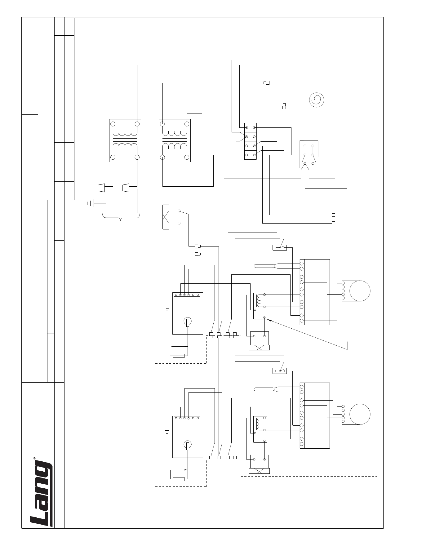
2M-W360: GAS SELECTRONIC GRIDDLE
NOTES:
THE BROWN WIRES ATTACHED TO THE RELAYS ARE
1.
ARE CONNECTED TO THE "NO" AND "COM" TERMINALS.
REV. DATE/ECO
DESCRIPTION OF CHANGE DR
24V
120V
BLK
WHT
WHT
YEL
BLU
RED
BLK
WHT
ORG
BLU
GRN
RED
BLK
2
5
4
3
1
6
5
4
3
2
1
GRN
ORG
YEL
BRN
ORG
BLU
RED
GRN
RED
BLK
1
2
5
4
3
1
9
8
7
5
6
2
6
5
4
3
2
1
BLK
WHT
GRN
ORG
BRN
YEL
RED
YEL
BRN BRN
BLK
YEL
YEL
YEL
RED
RED
RED
WHT
BLK
WHT
BLK
RED
YEL
PILOT
BURNER
BURNER
VALVE
PILOT
MODULE
RELAY
RTD
WHT
BLK
PILOT
VALVE
TEMPERATURE
CONTROL
BOARD
12 POSITION
SWITCH
BURNER
VALVE
RELAY
RTD
TEMPERATURE
CONTROL
BOARD
12 POSITION
SWITCH
SWITCHSWITCH
PILOT
BURNER
PILOT
MODULE
YEL
1
9
8
7
5
6
2
NO
COM
NO
COM
STAR MANUFACTURING INTERNATIONAL INC.
# 10 SUNNEN DRIVE
ST. LOUIS, MO. 63143, USA
DR:
CK:
DATE :
THIS DRAWING CONTAINS INFORMATION CONFIDENTIAL TO STAR MFG. INT'L
INC. NO REPRODUCTION OR DISCLOSURE OF ITS CONTENTS IS PERMITTED
TOLERANCE: UNLESS NOTED FRACTIONS ±3/64
DECIMALS
, .x
± .030, .xx ± .015, .xxx ± .005
REVISIONS
PART NO.
MODEL NO.
TITLE
MATERIAL
FINISH
ADAMS
9/23/14
2M-61122-W11-1
Wire Diagram - Selectronic Gas Griddles
L1N
BLK
BLK
BLK
WHT
WHT
BLK
BLK
INDICATOR
LAMP
POWER SWITCH
TERMINAL STRIP
TRANSFORMER
240V
SUPPLY
240V
120V
TRANSFORMER
ADDITIONAL SECTIONS
LIKE SECOND SECTION
POWER CONNECTION
& FIRST SECTION
SECOND SECTION
CONNECT TO
HOOD
SEE NOTE 1
2M-W360: GAS SELECTRONIC GRIDDLE
SK2404 Rev. A 7/18/13
Model: 224S thru 272S GAS SELECTRONIC GRIDDLE
1
2
3
5
6
7
9
10
11
14
15
16
17
18
19
20
21
22
23
24
25
Units mfg before July 2013 :SEE DETAIL A
Units mfg after July 2013 :SEE DETAIL B
13
12
8
4
Electrical Conduit

2M-W360: GAS SELECTRONIC GRIDDLE
Model No: 224S-NAT
Selectronic Electric Griddle
PARTS LIST March 3, 2015, Rev. J
IMPORTANT: WHEN ORDERING, SPECIFY VOLTAGE OR TYPE GAS DESIRED PAGE 1
INCLUDE MODEL AND SERIAL NUMBER OF 1
Some items are included for illustrative purposes only and in certain instances may not be available.
Description
Part
Number
Key
Number
1 K9-EZG-462-1 1 PLATE ASY 2’ SEL .5 GRV 224S
K9-EZG-462-02 1 PLATE ASY 2’SEL W/XLH-12 224SHE
K9-EZG-462-60 1 PLATE ASY-2’ SEL GRV CHROME 224SC
K9-EZG-462-W61 1 PLT ASSY 2’ SEL CHR 224SCHG
K9-EZGR-487-21 1 PLATE ASSY 2’ SEL EZGR RR 224SR
2 K9-41100-24 2 PROBE - ELECTRONIC #1517 224S, 224SR
3 K9-EZG-232-01 2 WELD BURNER #42 224S
4 2V-80501-04 1 GAS REG 3/4X3/4 CLS I 224S
6 K9-EZG-397 1 CENTER BURNER BAFFLE D 224S
7 K9-EZG-400 1 END BURNER BAFFLE 224S
8 2A-Z0314 4 FOOT, 4” DIE CAST 224S
9 2E-30304-22 2 SWTCB175-450oFW/41100-13 224S
10 2K-70801-07 6 SPACER SUPPORT 1/2LG 224S
11 2E-40101-19 2 CIRBD SI TEMP CNTRL NO 224S
12 2E-30303-18 2 SWTTOGON-OFFSPST1/4HP125V 224S
13 2E-30303-06 1 SWT TOG ON-ON DPDT BLK 224S
14 SY9-31601-09-1 1 PILOT LAMP 120V BLACK 224S
15 K9-EZG-W597 1 CONTROL PANEL ASSY 224S
K9-EZGR-W597 1 CONTROL PANEL 2’ SEL REAR 224SR
16 2M-60301-131 1 LABEL - ON / STAND BY 224S
17 2E-30303-05 2 SWT PLATE ON/OFF 224S
18 2M-60301-29 2 PNLLBL SELCT SWTDIAL 450o 224S
19 2R-70701-28 2 KNB BLK 1/4BUSH2SETSCW@90 224S
20 K9-60102-144 1 CONTROL PANEL COVER 2’ 224S
21 2M-60301-43 1 DIE CAST PLT LANG SATIN 224S
K9-60301-43-1 1 DIE CAST LOG + TINNERMAN 224S
23 2C-20103-02 AR SCRW SM PLT 10 X .5 PHLSL 224S
24 K9-EZG-349 1 GREASE DRAWER SLIDE 2’ 224S
K9-EZGR-352 1 SPOTWELD BUCKET SLIDE 224SR
25 K9-EZG-343 1 GREASE DRAWER ASSY 2’ 224S
K9-EZGR-338 1 SPOT GREASE DRAWER 224SR
NI 2C-9788 3 MAGNETIC CATCH W/STRIKE 224S
NI 2E-31107-02 1 CORD SET 14/3 X 8’ 15A 224S
NI 2E-EZG-712 2 HARNESS, SELECTRONIC 224S
NI 2K-70308-01 1 PIPE PLUG REG 1/8 NPT BLK 224S
NI 2M-60301-27 1 PNL LBL SLECTRONIC 4’ G4E 224S
NI 2P-50100-15 1 GRIDDLE SCRAPER 12” CROME UNITS
NI 2P-50100-15-1 - RE-FILL REPLACEMENTS CROME UNITS
NI 2P-50100-16 1 BOM AMI CLEANER CROME UNITS
NI 2P-50100-17 1 20” PALMYRA BRUSH CROME UNITS
Qty
Per

2M-W360: GAS SELECTRONIC GRIDDLE
Model No: 236S-LP, 236S-NAT, 236SC-NAT 236SCHG-NAT, 236SHE-NAT, 236SHG-NAT
Selectronic Gas Griddle
PARTS LIST March 3, 2015, Rev. J
IMPORTANT: WHEN ORDERING, SPECIFY VOLTAGE OR TYPE GAS DESIRED PAGE 1
INCLUDE MODEL AND SERIAL NUMBER OF 1
Some items are included for illustrative purposes only and in certain instances may not be available.
Description
Part
Number
Key
Number
1 K9-EZG-464-1 1 PLATE ASY 3’ SEL .5 GRV 236S
K9-EZG-464-01 1 PLATE ASY 3’ SEL .5 GRV 236SHG
K9-EZG-464-61 1 PLATE ASY 3’ SEL .5 GRV 236SCHG
K9-EZG-464-02 1 PLATE ASY 3’ SEL W/XLH-12 236SHE
K9-EZGR-487-301 1 PLATE ASY 3’ SEL REAR GUTTER CHROME 236SRC
K9-EZGR-487-32 1 PLATE ASY 3’ SEL REAR GUTTER 236SR
2 K9-41100-24 3 PROBE - ELECTRONIC #1517 ALL
3 K9-EZG-232-01 3 WELD BURNER #42 ALL
4 2V-80501-04 1 GAS REG 3/4X3/4 CLS I 236S-NAT
2V-80501-05 1 GAS REG 3/4X3/4 CLS II 236S-LP
6 K9-EZG-391 1 CENTER BURNER BAFFLE B ALL
7 K9-EZG-400 2 END BURNER BAFFLE ALL
8 2A-Z0314 4 FOOT, 4” DIE CAST ALL
9 2E-30304-22 3 SWTCB175-450oFW/41100-13 ALL
10 2K-70801-07 9 SPACER SUPPORT 1/2LG ALL
11 2E-40101-W19 3 CIRBD SI TEMP CNTRL NO ALL
12 2E-30303-18 3 SWTTOGON-OFFSPST1/4HP125V ALL
13 2E-30303-06 1 SWT TOG ON-ON DPDT BLK ALL
14 SY9-31601-09-1 1 PILOT LAMP 120V BLACK ALL
15 K9-EZG-600 1 SPOT CNTRL PNL 3’ SEL ALL
16 2M-60301-131 1 LABEL - ON / STAND BY ALL
17 2E-30303-05 3 SWT PLATE ON/OFF ALL
18 2M-60301-29 3 PNLLBL SELCT SWTDIAL 450o ALL
19 2R-70701-28 3 KNB BLK 1/4BUSH2SETSCW@90 ALL
20 K9-60102-42 1 CONTROL PANEL COVER 3’ ALL
21 2M-60301-43 1 DIE CAST PLT LANG SATIN ALL
21 K9-60301-43-1 1 DIE CAST LOG + TINNERMAN ALL
23 2C-20103-02 AR SCRW SM PLT 10 X .5 PHLSL ALL
24 K9-EZG-355 1 GREASE DRAWER SLIDE ALL
25 K9-50303-11 1 GREASE DRAWER ASSY ALL
NI 2C-9788 3 MAGNETIC CATCH W/STRIKE ALL
NI 2E-31107-02 1 CORD SET 14/3 X 8’ 15A ALL
NI 2E-EZG-712 3 HARNESS, SELECTRONIC ALL
NI 2K-70308-01 1 PIPE PLUG REG 1/8 NPT BLK ALL
NI 2M-60301-27 1 PNL LBL SLECTRONIC 4’ G4E ALL
NI 2P-50100-15 1 GRIDDLE SCRAPER 12” CROME UNITS
NI 2P-50100-15-1 - RE-FILL REPLACEMENTS CROME UNITS
NI 2P-50100-16 1 BOM AMI CLEANER CROME UNITS
NI 2P-50100-17 1 20” PALMYRA BRUSH CROME UNITS
Qty
Per

2M-W360: GAS SELECTRONIC GRIDDLE
Model No: 248S-LP, 248S-NAT, 248S-NATSC, 248SHG-NAT, 248SHE-NAT
Selectronic Gas Griddle
PARTS LIST March 3, 2015, Rev. J
IMPORTANT: WHEN ORDERING, SPECIFY VOLTAGE OR TYPE GAS DESIRED PAGE
INCLUDE MODEL AND SERIAL NUMBER OF
Some items are included for illustrative purposes only and in certain instances may not be available.
Description
Part
Number
Key
Number
1 K9-EZG-467-01 1 PLATE ASY 4’SEL .5 GRV 248SHG-NAT
K9-EZG-467-02 1 PLATE ASY 4’SEL .5 GRV W/XLH12 248SHE-NAT
K9-EZG-467-1 1 PLATE ASY 4’SEL .5 GRV 248S-NAT/NATSC/LP
K9-EZG-467-61 1 PLATE ASY 4’ SEL CHROME 248SCHG-NAT
K9-EZG-467-W1 1 PLATE ASY 4’ SEL CHROME 248SC
K9-EZGR-487-42 1 PLATE ASY 4’ SEL REAR 248SR
2 K9-41100-24 4 PROBE - ELECTRONIC #1517 248S
3 K9-EZG-232-01 4 WELD BURNER #42 248S
4 2V-80501-04 1 GAS REG 3/4X3/4 CLS I 248S-NAT
2V-80501-05 1 GAS REG 3/4X3/4 CLS II 248S-LP, 248SHG-LP
5 K9-EZG-388 1 CENTER BURNER BAFFLE A 248S
6 K9-EZG-391 1 CENTER BURNER BAFFLE B 248S
7 K9-EZG-400 2 END BURNER BAFFLE 248S
8 2A-Z0314 4 FOOT, 4” DIE CAST 248S
9 2E-30304-22 4 SWTCB175-450oFW/41100-13 248S
10 2K-70801-07 12 SPACER SUPPORT 1/2LG 248S
11 2E-40101-19 4 CIRBD SI TEMP CNTRL NO 248S
12 2E-30303-18 4 SWTTOGON-OFFSPST1/4HP125V 248S
13 2E-30303-06 1 SWT TOG ON-ON DPDT BLK 248S
14 SY9-31601-09-1 1 PILOT LAMP 120V BLACK 248S
15 K9-EZG-W603 1 SPOT CNTRL PNL 4’ SEL 248S
K9-EZGR-W605 1 SPOT CNTRL PNL 4’ SEL 248SR
16 2M-60301-131 1 LABEL - ON / STAND BY 248S
17 2E-30303-05 4 SWT PLATE ON/OFF 248S
18 2M-60301-29 4 PNLLBL SELCT SWTDIAL 450o 248S
19 2R-70701-28 4 KNB BLK 1/4BUSH2SETSCW@90 248S
20 K9-60102-122 1 PANEL COVER ASSY 4FT EZG 248S-NAT/LP
21 2M-60301-43 1 DIE CAST PLT LANG SATIN 248S
K9-60301-43-1 1 DIE CAST LOG + TINNERMAN 248S
23 2C-20103-02 50 SCRW SM PLT 10 X .5 PHLSL 248S
24 K9-EZG-355 1 GREASE DRAWER SLIDE 248S
25 K9-50303-11 1 GREASE DRAWER ASSY 248S-NAT/LP
K9-EZG-977 1 GREASE DRAWER ASSY 248S-NATSC
K9-EZGR-338 1 SPOT GREASE DRAWER 248SR
NI 2E-31107-02 1 CORD SET 14/3 X 8’ 15A 248S
NI 2K-70308-01 1 PIPE PLUG REG 1/8 NPT BLK 248S
NI 2M-60301-27 1 PNL LBL SLECTRONIC 4’ G4E 248S-NAT/LP
NI 2C-9788 3 MAGNETIC CATCH W/STRIKE 248S
NI 2E-EZG-712 4 HARNESS, SELECTRONIC 248S
NI 2P-50100-15 1 GRIDDLE SCRAPER 12” CROME UNITS
NI 2P-50100-15-1 - RE-FILL REPLACEMENTS CROME UNITS
NI 2P-50100-16 1 BOM AMI CLEANER CROME UNITS
NI 2P-50100-17 1 20” PALMYRA BRUSH CROME UNITS
1
1
Qty
Per

2M-W360: GAS SELECTRONIC GRIDDLE
Model No: 260S-LP, 260S-NAT, 260S-NATSC
Selectronic Gas Griddle
PARTS LIST March 3, 2015, Rev. J
IMPORTANT: WHEN ORDERING, SPECIFY VOLTAGE OR TYPE GAS DESIRED PAGE 1
INCLUDE MODEL AND SERIAL NUMBER OF 1
Some items are included for illustrative purposes only and in certain instances may not be available.
Description
Part
Number
Key
Number
1 K9-EZG-470-1 1 PLATE ASY 5’SEL .5 GRV 260S
K9-EZG-470-61 1 PLATE ASSY 5’ SEL. CHROME 260SCHE-NAT
K9-EZG-470-60 1 PLATE ASSY 5’ SEL. CHROME 260SC
2 K9-41100-24 5 PROBE - ELECTRONIC #1517 260S
3 K9-EZG-232-01 5 WELD BURNER #42 260S
4 2V-80501-04 1 GAS REG 3/4X3/4 CLS I 260S-NAT
4 2V-80501-05 1 GAS REG 3/4X3/4 CLS II 260S-LP
5 K9-EZG-388 1 CENTER BURNER BAFFLE A 260S
6 K9-EZG-391 2 CENTER BURNER BAFFLE B 260S
7 K9-EZG-400 2 END BURNER BAFFLE 260S
8 2A-Z0314 4 FOOT, 4” DIE CAST 260S-NAT, 260S-LP
2R-200716 4 LEG, 2.5 IN METAL 260S-NATSC
9 2E-30304-22 5 SWTCB175-450oFW/41100-13 260S
10 2K-70801-07 15 SPACER SUPPORT 1/2LG 260S
11 2E-40101-19 5 CIRBD SI TEMP CNTRL NO 260S
12 2E-30303-18 5 SWTTOGON-OFFSPST1/4HP125V 260S
13 2E-30303-06 1 SWT TOG ON-ON DPDT BLK 260S
14 SY9-31601-09-1 1 PILOT LAMP 120V BLACK 260S
15 K9-EZG-606 1 SPOT CNTRL PNL 5’ SEL 260S
16 2M-60301-131 1 LABEL - ON / STAND BY 260S
17 2E-30303-05 5 SWT PLATE ON/OFF 260S
18 2M-60301-29 5 PNLLBL SELCT SWTDIAL 450o 260S
19 2R-70701-28 5 KNB BLK 1/4BUSH2SETSCW@90 260S
20 K9-EZG-620 1 CONTROL PANEL 5’ COVER 260S-NAT, 260S-LP
21 2M-60301-43 1 DIE CAST PLT LANG SATIN 260S
K9-60301-43-1 1 DIE CAST LOG + TINNERMAN 260S
22 2C-20602-04 2 TINNERAMN SPD NUT 1/8” DIA ALL
23 2C-20103-02 AR SCRW SM PLT 10 X .5 PHLSL 260S
24 K9-EZG-355 2 GREASE DRAWER SLIDE 260S
25 K9-50303-11 2 GREASE DRAWER ASSY 260S
NI 2C-9788 3 MAGNETIC CATCH W/STRIKE 260S
NI 2E-31107-02 1 CORD SET 14/3 X 8’ 15A 260S
NI 2E-EZG-712 5 HARNESS, SELECTRONIC 260S
NI 2K-70308-01 1 PIPE PLUG REG 1/8 NPT BLK 260S
NI 2M-60301-27 1 PNL LBL SLECTRONIC 4’ G4E 260S
NI 2P-50100-15 1 GRIDDLE SCRAPER 12” CROME UNITS
NI 2P-50100-15-1 - RE-FILL REPLACEMENTS CROME UNITS
NI 2P-50100-16 1 BOM AMI CLEANER CROME UNITS
NI 2P-50100-17 1 20” PALMYRA BRUSH CROME UNITS
Qty
Per
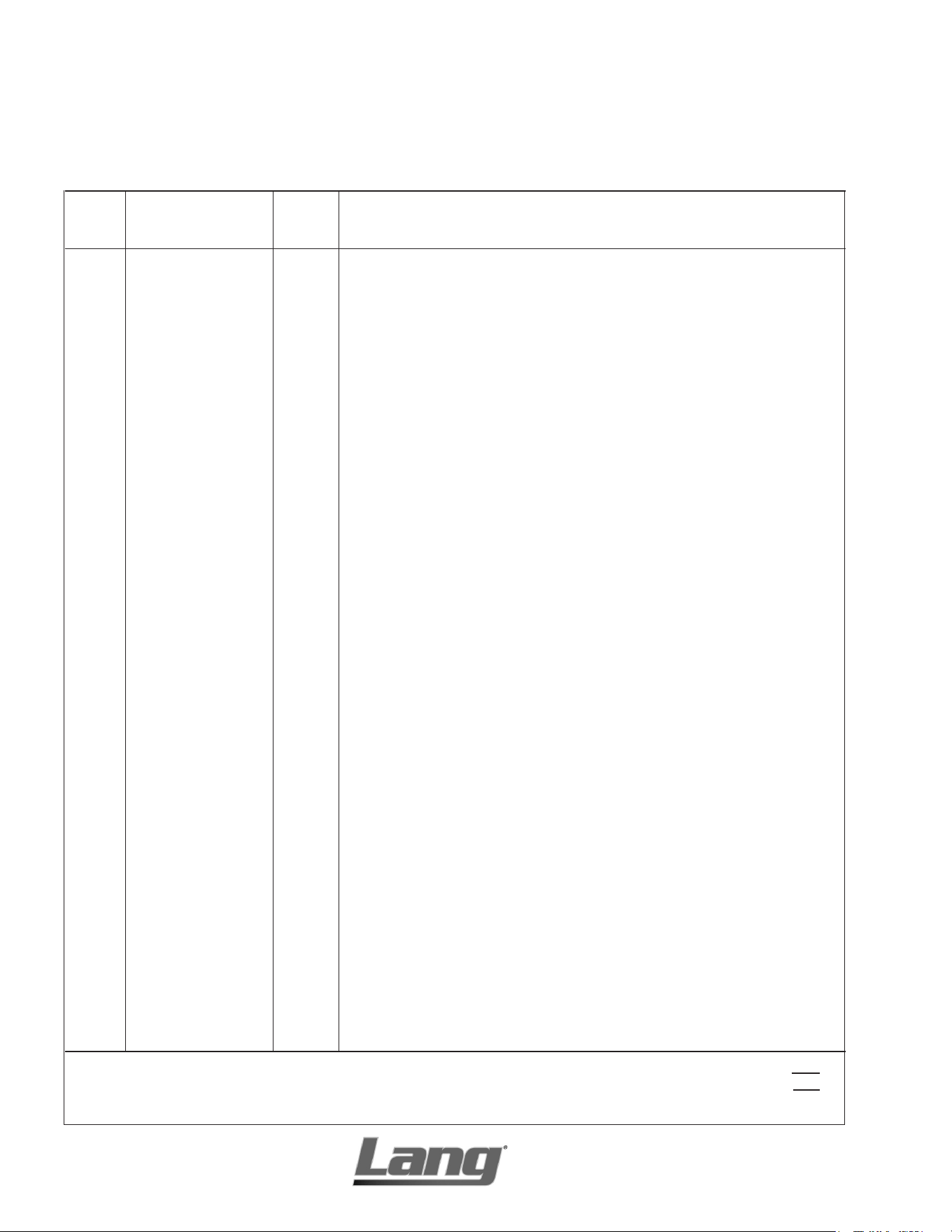
2M-W360: GAS SELECTRONIC GRIDDLE
Model No: 272S-NAT, 272S-LP, 272S-NATSC, 272SHG
Selectronic Gas Griddle
PARTS LIST March 3, 2015, Rev. J
IMPORTANT: WHEN ORDERING, SPECIFY VOLTAGE OR TYPE GAS DESIRED PAGE 1
INCLUDE MODEL AND SERIAL NUMBER OF 1
Some items are included for illustrative purposes only and in certain instances may not be available.
Description
Part
Number
Key
Number
1 K9-EZG-473-1 1 PLATE ASY 6’SEL .5 GRV 272S
K9-EZG-473-01 1 PLATE ASY 6”SEL .5 GRV W/AGC 272SHG
K9-EZG-473-02 1 PLATE ASY 6’SEL W/XLH-12 272SHE
K9-EZG-473-03 1 PLATE ASY 6’ SEL CHROME 272SCHE
K9-EZGR-487-6 1 PLATE ASY 6’ SEL EZGR .5 272SB
2 K9-41100-24 6 PROBE - ELECTRONIC #1517 ALL
3 K9-EZG-232-01 6 WELD BURNER #42 ALL
4 2V-80501-04 1 GAS REG 3/4X3/4 CLS I 272S-NAT
2V-80501-05 1 GAS REG 3/4X3/4 CLS II 272S-LP
5 K9-EZG-394 2 CENTER BURNER BAFFLE C ALL
6 K9-EZG-391 2 CENTER BURNER BAFFLE B ALL
7 K9-EZG-400 2 END BURNER BAFFLE ALL
8 2A-Z0314 6 FOOT, 4” DIE CAST ALL
9 2E-30304-22 6 SWTCB175-450oFW/41100-13 ALL
10 2K-70801-07 18 SPACER SUPPORT 1/2LG ALL
11 2E-40101-19 6 CIRBD SI TEMP CNTRL NO ALL
12 2E-30303-18 6 SWTTOGON-OFFSPST1/4HP125V ALL
13 2E-30303-06 1 SWT TOG ON-ON DPDT BLK ALL
14 SY9-31601-09-1 1 PILOT LAMP 120V BLACK ALL
15 K9-EZG-609 1 SPOT CNTRL PNL 6’ SEL 272S
K9-EZGR-609-1 1 SPOT CNTRL PNL 6’ SEL 272SB
16 2M-60301-131 1 LABEL - ON / STAND BY ALL
17 2E-30303-05 6 SWT PLATE ON/OFF ALL
18 2M-60301-29 6 PNLLBL SELCT SWTDIAL 450o ALL
19 2R-70701-28 6 KNB BLK 1/4BUSH2SETSCW@90 ALL
20 K9-EZG-615 2 CONTROL PANEL COVER 3’ ALL
21 2M-60301-43 1 DIE CAST PLT LANG SATIN ALL
K9-60301-43-1 1 DIE CAST LOG + TINNERMAN ALL
22 2C-20602-04 2 TINNERAMN SPD NUT 1/8” DIA ALL
23 2C-20103-02 AR SCRW SM PLT 10 X .5 PHLSL ALL
24 K9-EZG-355 2 GREASE DRAWER SLIDE 272S
K9-EZGR-352 2 SPOTWELD BUCKET SLIDE 272SB
25 K9-50303-11 2 GREASE DRAWER ASSY 272S
K9-EZGR-338 2 SPOT GREASE DRAWER 272SB
NI 2C-9788 6 MAGNETIC CATCH W/STRIKE 272S
NI 2E-30501-03 2 TERM STRP 4 POLE W/PUSH 272SB
NI 2E-31107-02 1 CORD SET 14/3 X 8’ 15A ALL
NI 2E-EZG-712 6 HARNESS, SELECTRONIC ALL
NI 2K-70308-01 2 PIPE PLUG REG 1/8 NPT BLK ALL
NI 2M-60301-27 1 PNL LBL SLECTRONIC 4’ G4E ALL
NI 2P-50100-15 1 GRIDDLE SCRAPER 12” CROME UNITS
NI 2P-50100-15-1 - RE-FILL REPLACEMENTS CROME UNITS
NI 2P-50100-16 1 BOM AMI CLEANER CROME UNITS
NI 2P-50100-17 1 20” PALMYRA BRUSH CROME UNITS
Qty
Per
2M-W360: GAS SELECTRONIC GRIDDLE
1
3
2
4
5
6
5
7
8
9
10
15
15
20
19
18
15
14
16
5
17
10
11
13
12
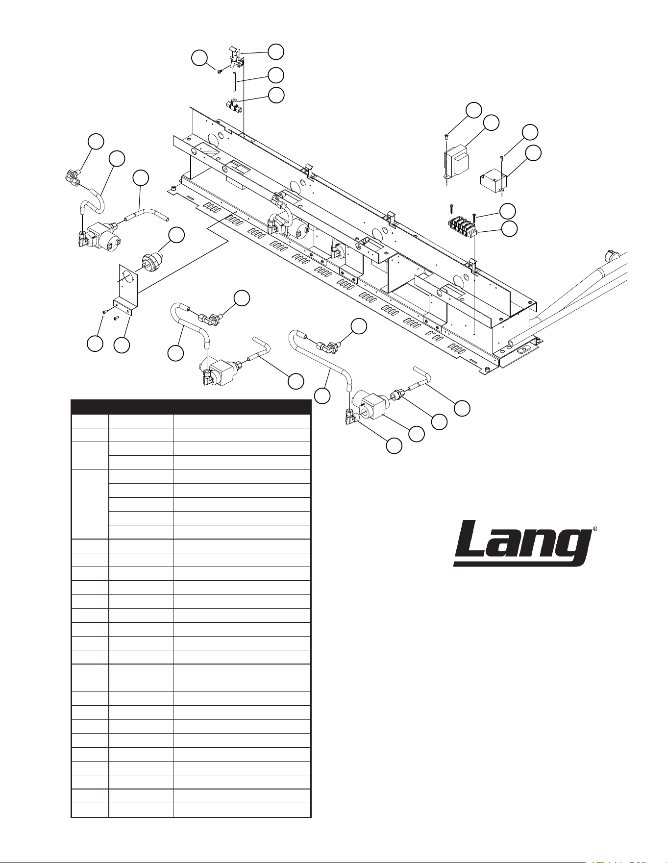
Model: Selectronic & ACCU-TEMP MANIFOLD ASSY
DETAIL A
(manufactured before July 2013)
SK2405 Rev.A 7/18/2013
Manifold Assy, units Mfg Before July 2013
Fig No. Part Number Description
1 2C-20103-02 SCRW SM PLT 10 X .5 PHLSL
2
K9-EZG-995 PILOT ASSEMBLY, LF MNT
K9-EZG-996 PILOT ASSEMBLY, RT MNT
3
K9-EZG-637 PILOT TUBE #1
K9-EZG-640 PILOT TUBE #2
K9-EZG-643 PILOT TUBE #3
K9-EZG-650 PILOT TUBE #5
K9-EZG-655 PILOT TUBE #9
4 2K-70101-07 BRAS TBE TEE 1/4CC
5 2C-20102-04 SCRW PHD ST 8-32X.5 PLTD
6 2E-31400-07 XFORMR120-208-240/24V40VA
7 2J-80300-03 SPRK IGNITR MODULE SM2
9 2E-30501-03 TERM STRP 4 POLE W/PUSH
10 K9-EZG-628 SOLENOID TUBE A
11 2K-70101-11 BRAS TBE UNON 3/8CC-1/2
12 2V-80502-03 SLENOID VLVE 24VAC 1/2
13 2K-70101-12 BRAS TBE ELBW 3/8CC-1/2
14 K9-EZG-671 BURNER FEED TUBE #3
15 2A-W1185 ORIFICE FITTING - 90 DEG
16 K9-EZG-668 BURNER FEED TUBE #2
17 K9-EZG-288 FLAME SWITCH MOUNT
18 2V-80506-01 FLAME SWT 24 GAS GRID &
19 K9-EZG-631 SOLENOID TUBE B
20 K9-EZG-665 BURNER FEED TUBE #1
NI 2A-45408 ORIFICE HOOD .0935 #42
NI 2A-80400-12 ORIFICE HOOS .0595 #53
NI 2A-80401-03 PILTBRNER ORIFICE .0115LP
NI 2E-40101-19 CIRBD SI TEMP CNTRL NO
March 3, 2015, Rev. J
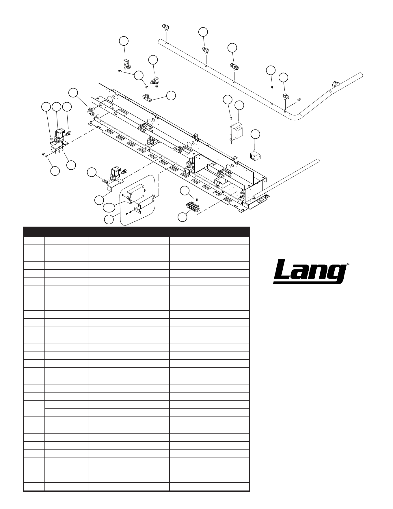
2M-W360: GAS SELECTRONIC GRIDDLE
1
2
3
1
4
7
8910
6
12
13
11
14
15
15a
16
5
18
19
17
6
DETAIL B
(manufactured after July 2013)
SK2671 Rev. E 11/23/2021
20
Manifold Assy, units Mfg After July 2013
Fig No. Part Number Description Application
1 2K-70101-03 BRASTBEELBOW 1/4NPT-3/8CC
2 2K-70101-06 BRASTEE BRNCH 1/4NPTM-3/8
3 2K-70308-01 PIPE PLUG REG 1/8 NPT BLK
4 K9-EZG-996 PILOT ASSEMBLY, RT MNT
5 K9-EZG-995 PILOT ASSEMBLY, LF MNT
6 2C-20103-02 SCRW SM PLT 10 X .5 PHLSL
7 2A-W1185 ORIFICE FITTING - 90 DEG
8 2K-45300 FITTING 3/8CC X 1/8NPT
9 2V-80502-W07 VALVE SOLENOID-1/8 NPT
10 2K-70101-124 FITTING 1/8NPT X 3/8COMP.
11 2V-6671 VALVE-LINCOLN BRASS#3817
12 2C-20102-08 SCRW PHD ST 8-32X.375
13 K9-EZG-W297 BRKT,SOLENOID VALVE
14 2C-20102-04 SCRW PHD ST 8-32X.5 PLTD
15 PS-60101-W15 KIT, PILOT IGNITION CONTROL mfg between 7/13 & 3/15
15a 2J-80300-W20-1 PILOT IGNITION MODULE mfg after 3/1/2015
16 2E-30501-03 TERM STRP 4 POLE W/PUSH
17 2K-70101-07 BRAS TBE TEE 1/4CC
18 2C-20102-04 SCRW PHD ST 8-32X.5 PLTD
19
2E-31400-07 XFORMR120-208-240/24V40VA
2E-31400-37 XFORMER 240V TO 120V 240V, 224SR-LP24, 248SR-LP24
20 2E-30600-W14 RELAY 277 VAC SPST 30A
NI 2K-70104-03 FLEXIBLE TUBE 3/8OD X 8
NI 2K-80101-05 TUBE FLEX 1/4 DIA X 6 LNG
NI 2K-Z4921 BURNER TUBE FLEX 3/8 OD
NI 2K-Z6081 PILOT TUBE FLEX 10”
NI 2K-Z6943 GAS LINE 1/4”D x 8”L
NI 2K-Z6945 GAS LINE 1/4”D x 16”L BBQ
NI 2A-45408 ORIFICE HOOD #42 GRID NAT NAT
NI 2A-80400-12 ORIFICE HOOD .0595 #53, LP LP
March 3, 2015, Rev. J

2M-W360: GAS SELECTRONIC GRIDDLE
LANG_WARRANTY 2023 FINAL v2
LIMITED EQUIPMENT WARRANTY
Lang Manufacturing warrants to the original purchaser of new Lang
products to be free from defects in material or workmanship, under normal
and proper use and maintenance service as specified by Lang and upon
proper installation and start-up in accordance with the instructions
supplied with each Lang unit. Lang’s obligation under this warranty is
limited to a period of one [1] year beginning from the date of original
installation. The warranty period begins upon the earlier of the date of
original installation or up to six [6] months after the original shipment, from
the factory, of the covered product. Defects that occur as a result of normal
use, within the time period and limitations defined in this warranty, will at
Lang’ discretion have the parts replaced or repaired by Lang or a Lang-
authorized service agency.
THIS WARRANTY IS SUBJECT TO ALL LISTED CONDITIONS
Repairs performed under this warranty are to be performed by a Lang
authorized service agency. Lang will not be responsible for charges incurred
or service performed by non-authorized repair agencies. In all cases, the
nearest Lang-authorized service agency must be used. Lang will be
responsible for normal labor charges incurred in the repair or replacement
of a warrantied product within 50 miles (80.5 km) of an authorized service
agency. Time and expense charges for anything beyond that distance will
be the responsibility of the owner. All labor will need to be performed
during regular service hours. Any overtime premium will be charged to the
owner. For all shipments outside the U.S.A. and Canada, please see the
International Warranty for specific details. It is the responsibility of the
owner to inspect and report any shipping damage claims, hidden or
otherwise, promptly following delivery. No mileage or travel charges will be
honored on any equipment that is deemed portable. In general, equipment
with a cord and plug weighing less than 50 lb. (22.7 kg) is considered
portable and should be taken or shipped to the closest authorized service
agency, transportation prepaid.
CONTACT
Should you require any assistance regarding the operation or maintenance
of any Lang Manufacturing; phone or email our service department. In all
correspondence provide the model number and serial number of the unit
needing service; include the voltage or gas type.
Normal Business Hours: 8:00 a.m. to 4:30 p.m. Central
Telephone: 800-264-7827 Tech Service Option 2
Email: [email protected]
www.LangWorld.com
PRODUCTS
PARTS
LABOR
Lang Strato Series™
convection ovens
2 years 2 years
Lang convection oven doors
(excluding hardware)
lifetime 2 years
Lang griddles 2 years 2 years
Chrome griddle surfaces
[against peeling]
5 years
Cast iron grates, burners
and burner shields
1 year
Original Lang parts sold to repair
Lang equipment
90 days
Lang Ranges 2 years 2 years
Lang Marine 2 years 2 years
WARRANTY EXCLUSIONS
THE FOLLOWING WILL NOT BE COVERED UNDER WARRANTY.
Lang’s sole obligation under this warranty is limited to either repair or
replacement parts, subject to the additional limitations detailed
below. This warranty neither assumes nor authorizes any person to
assume obligations other than those expressly covered by this
warranty.
• Any product which has not been used, maintained, or installed in
accordance with the directions published in the appropriate
installation sheet and/or owner’s manual, including incorrect gas or
electrical connection. Lang is not liable for any unit which has been
mishandled, abused, misapplied, subjected to harsh chemicals,
modified by unauthorized personnel, damaged by flood, fire, or other
acts of nature [or God], or which have an altered or missing serial
number.
• Installation, labor, and job checkouts, calibration of heat controls,
air and gas burner/bypass/pilot adjustments, gas or electrical system
checks, voltage and phase conversions, cleaning of equipment, or
seasoning of griddle surface.
• Replacement of fuses or resetting of circuit breakers, safety
controls, or reset buttons.
• Replacement of broken or damaged glass components, quartz
heating elements, and light bulbs.
• Labor charges for all removable and consumable parts in gas
charbroilers and hotplates, including but not limited to burners,
grates, and radiants.
• Any labor charges incurred by delays, waiting time, or operating
restrictions that hinder a service technician’s ability to perform
service.
• Replacement of parts that fail or are damaged due to normal wear
or labor for replacement of parts that can be replaced during a daily
cleaning routine, such as but not limited to silicone belts, PTFE non-
stick sheets, control labels, knobs, bulbs, fuses, quartz heating
elements, baskets, racks, and grease drawers.
• Any economic loss of business or profits.
• Non-OEM parts. Use of non-OEM parts without Lang’s approval will
void the warranty.
• Components that should be replaced when damaged or worn, but
have been field-repaired instead [e.g. field-welded fry pots]
• Units exceeding one [1] year from original installation date.
ADDITIONAL WARRANTIES
• Specific/chain-specific equipment may have additional and/or
extended warranties.
The foregoing warranty is in lieu of any, and all other warran�es
expressed or implied and cons�tutes the en�re warranty.

S
S
T
T
A
A
R
R
H
H
O
O
L
L
D
D
I
I
N
N
G
G
S
S
G
G
R
R
O
O
U
U
P
P
265 HOBSON ST. SMITHVILLE, TN 37166
(800) 264-7827
www.starholdingsgrp.com