
HELA 1650R Platinum
HELA Series
Cybenetics Platinum 1650W ATX 3.1 & PCIe 5
Fully Modular ATX Power Supply
Supports 12V-2x6 PCIe connector with ATX 3.1 and PCIe Gen 5 standard
High efficiency with Cybenetics Platinum certification
24/7 continuous power output with 50℃ operating temperature
Strict ±2% voltage regulation and low ripple & noise
Dual EPS 8pin with multiple PCI-E 8 / 6pin connectors support
Ultra silent 135mm FDB fan with intelligent semi-fanless operation
Compact design with a depth of 180mm for easy integration

01
SPECIFICATION
SilverStone HELA Series
HELA 1650R Platinum
1650W
ATX12V / EPS 12V Switching Power Supply With
Active PFC
Cybenetics Platinum
PS/2
1.1 Scope
1.General
This specification defines the performance characteristics of a single phase
1650 watts, 5output power supply . This specification also defines worldwide
safety and electromagnetic compatibility requirements for the power supply
which is intended for use in computer products.
* The power supply must operate at above frequency with 90-264 VACrms input
voltage range.
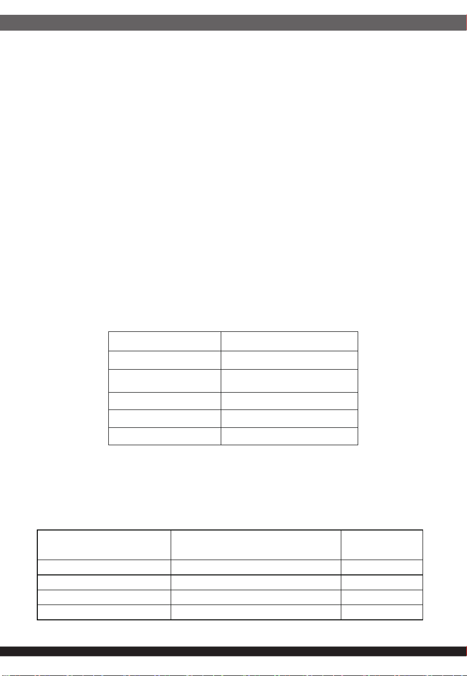
2.1 Input Voltage
2.2 Input Frequency
2.Input Characteristics
Nominal Voltage Voltage Variation Range
----------------------- ------------------------------------
100 - 240 Vrms 90 - 264 Vrms
Nominal Frequency
Frequency Variation Range
------------------------ --------------------------------
50-60 Hz
47 Hz to 63 Hz
02
2.3 Max. Input AC Current
2.4 Inrush Current
2.5 Efficiency
3.1 Normal Operation Output
The power supply must meet inrush requirements for any rated AC voltage,
during turn on at any phase of AC voltage, during a single cycle AC dropout
condition, during repetitive ON/OFF cycling of AC, and over the specified
temperature range. The peak inrush current shall be less than the ratings of
its critical components (including input fuse, bulk rectifiers, and surge limiting
device).
Efficiency versus Load for ENERGY STAR*, at 115V/60Hz and 230V/50Hz
Max. Input Current Measuring Range
------------------------ -----------------------
20~16A 100 - 240 Vrms
3. Output characteristics
•Maximum continuous total DC output power should not exceed 1650W
•Maximum continuous combined load on +3.3VDC and +5VDC outputs shall
not exceed 130W.
•Maximum combined load on +12V output rails shall not exceed 1650W
NOTE:
Noise test should be measured with 20 MHz bandwidth frequency oscilloscope.
The output terminal shall add a tantalum capacitor of 10uF in parallel with a
ceramic capacitor of 0.1uF.
Loading
Full Load
(100%)
Typical Load
(50%)
Light
Load
(20%)
Low Load
(2%)
PFC@
50%Load
Minimum
Efficiency
87% 90%
87% 60%
≥0.9
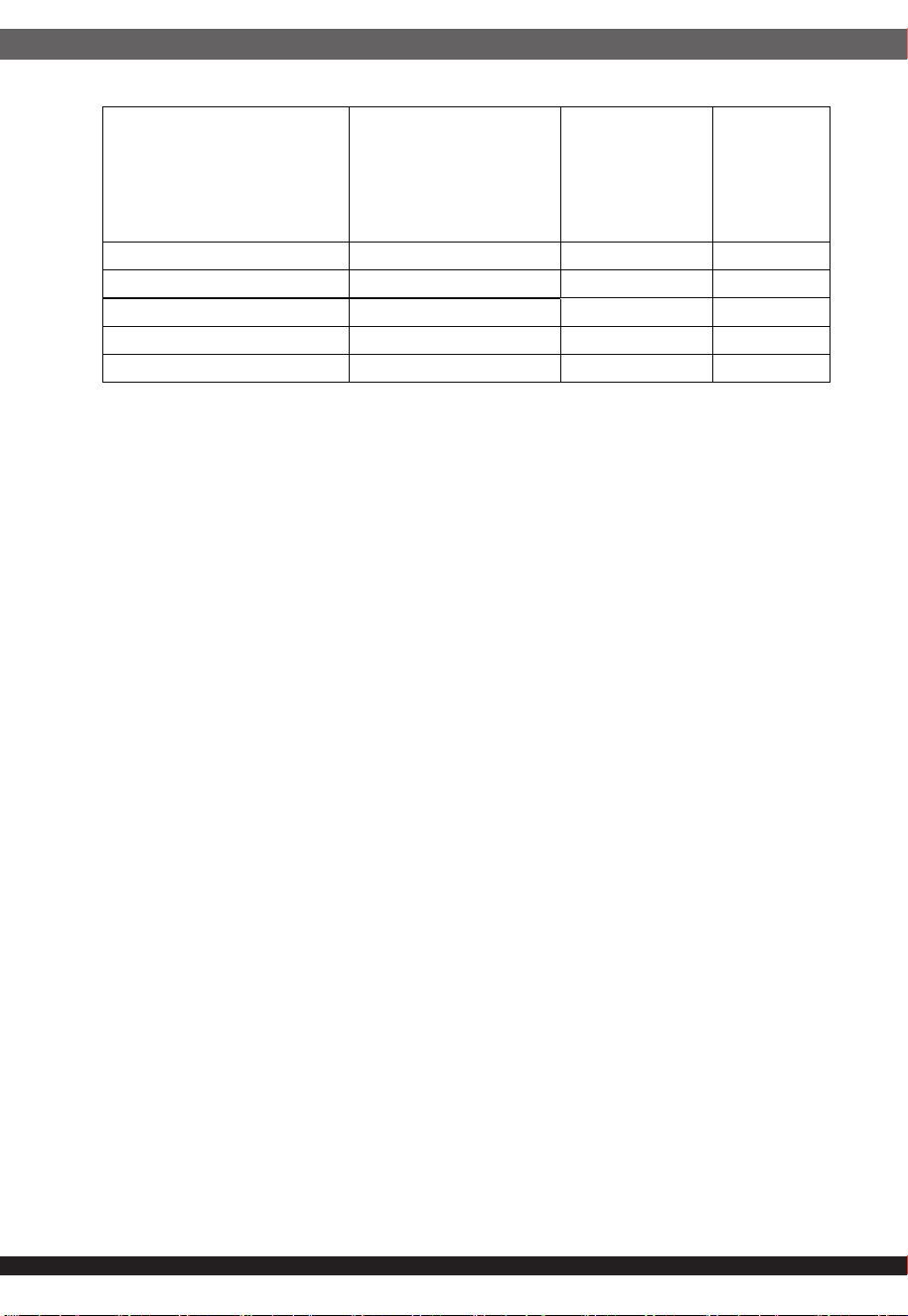
Output
Voltage
Load
MIN
Range
MAX
Load
Regulation
Total
Regulation
Ripple & Noise
P-P Max.
+5V 0.0A 25A
±3% ±5%
40mV
+12V 0.0A 137.5A
±3%
+5% /-7% 80mV
–12V 0.0A 0.3A
±5% ±10%
80mV
+5Vs 0.0A 3.0A
±5% ±5%
40mV
+3.3V 0.0A 25A
±3% ±5%
40mV
03
3.2 Remote On/Off Controlled mode
3.3 Regulation
The PSON# signal is required to remotely turn on/off the power supply, PSON#
is an active low signal that turns on the output power rails. When this is not
pulled low by the system, or left open, the outputs (except the +5VSB) turn off.
This signal is pulled to a standby voltage by a pull-up resistor internal to
the power supply.
TTL level "H" 2.0 V - 5.25 V
"L" 0.0 V – 1.0 V
The cross regulation defined as follows, the output regulation should be within
the specified range.
3.4 Rise Time
DC output rise time is less than 20 mS at nominal line and full load.
3.5 +5V DC / +3.3V DC Power Sequencing
The +12V and +5V output levels must be equal to or greater than the +3.3V
output at all times during power-up and normal operation. The time between
any output of + 12V and +5V reaching its minimum in-regulation level and
+3.3V reaching its minimum in-regulation level must be ≤ 20mS.
3.6 Hold-up Time
PG output maintains at least 16mS is 60% 1oad after power off which hold within
para 3.1 under 115V/60Hz and 230V/50Hz condition.
3.7 5VSB
5VSB is requierd for the implementation of PS-ON described above. 5VSB is a
tandby voltage that may be used to power circuits that require power input
during the powered-down state of all power rails. The 5 VSB pin should deliver
5V ± 5% at a minimum of 3.0 A for PC board circuits to operate. Conversely,
PC board should draw no more than 3.0A maximum form this pin. This power
may be used to operate circuits such as soft power control
Load +5V +3.3V +12V -12V +5Vsb
Low Load 0.287A 0.287A 2.523A 0.0056A 0.055A
Light Load 2.87A 2.87A 25.23A 0.06A 0.55A
Typical Load 7.18A 7.18A 60.07A 0.14A 1.38A
Full Load 14.37A 14.37A 126.14A 0.28A 2.75A
04
3.10 Capacitive Load
The power supply should be able to power up and operate normally with the
following capacitances simultaneously present on the DC outputs.
3.11 Support PCIE 12V-2x6 Power
3.11.1 PCI Express* 12V-2x6 Connector Power Limits
3.9 3.3V Sense
A default 3.3V sense line should be implemented pin 13 of the connector.
Output Capacitive load (uF)
+5V 3300
+12V 3300
+3.3V 3300
-12V 330
+5VS 3300
3.8 PG-OK
PG-OK is a power good signal and should be asserted high by power supply
to indicate that the +5 VDC and +3.3 VDC outputs are above the under-voltage
thresholds of the power supply. When this signal is asserted high, there should
be sufficient mains energy stored by the converter to guarantee continuous
power operation within specification. Conversely, when either the +5VDC or the
+3.3VDC output voltage falls below the under-voltage threshold, or when
mains power has been removed for a time sufficiently long so that power supply
operation is no longer guaranteed, PG-OK should be deasserted to a low state.
See Figure 1 for a representation of the timing characteristics of the PG-OK,
PS-ON, and germane power rail signals.
Initial Permitted Power at
System Power Up
Maximum Sustain Power after
Software Configuration
Support type
375 W 600 W
225 W 450 W
150 W 300 W
100 W 150 W
05
3.11.2 PCIe* AIC and PSU Power Budget used for Peak Power Excursion
% of PSU Rated Size
PSU ≤ 450 Watts & PSUs
without 12VHPWR
Connector
Power Excursion % of
PSU Rated Size
PSU > 450 Watts &
12VHPWR Connector
present
Time for Power
Excursion (TE)
Testing
Duty Cycle
100% 100% Infinite
--
110% 120% 100ms 50%
135% 160% 10ms 25%
145% 180% 1ms 20%
150% 200% 100 us 10%
4.1 Input Protection
In primary circuit of the power supply , a protected fuse is inserted. Only internal
fault of the power supply will cause the fuse blown. Any overload or short circuit
at DC output will keep from fuse brown or fire hazard.
4.2 Output Protection
4.2.1 Under voltage protection
The +12V/+5V/+3.3V DC output are protected against the under voltage
condition range value can't be exceed 10.3~11.0V at 12V terminal and
3.3~3.7V at 5V, 2.0~2.4V at 3.3V.
4.2.2 Over Voltage Protection
The +12V/+5V/+3.3V DC output are protected against the over voltage
condition. Maximum value can't be over 15.6V at 12V terminal and 7.0V
at 5V, 4.3V at 3.3V.
4.2.3 Over Power Protection
The power supply can be used electronic circuit to limit the output current
against exceeding 30-70% of surge output power or protected against
excessive power delivery since short circuit of any output or over total
power at high line.
4.2.4 Short Circuit Protection
Short circuit placed on +5V,+12V,+3.3V,-12V will latch off. +5VSB will
auto-recovery.
4. Protection

06
4.2.5 Over-Current Protection
Current protection should be designed to limit the current to operate within
safe operating conditions.Over current protection schemes where only the
voltage output that experiences the over current event is shut off may be
adequate to maintain safe operation of the power supply and the system;
however, damage to the motherboard or other system components may
occur. The recommended over current protection scheme is for the
power supply to latch into the shutdown state. The setting of over current
protection for each output rail is as following.
+5V is less than or equal to 25.5~37.5A..
+3.3V is less than or equal to 25.5~37.5A.
+12V is less than or equal to 178.75~233.75A
4.2.6 Over-Temperature Protection
This power supply includes an over-temperature protection sensor, which can
trip and shut down the power supply at 65℃ ±10℃
5.1 No Load Start
When power is applied to DA1650-G with no load connected or under minimum
load connected, neither damage to power supply nor hazards to users will occur.
5.2 Cold Start
The power supply shall operate properly when first applied at normal input
voltage and or so maximum load after 4 hours storage in 0℃ environment.
The power supply can operate normally at any altitude between
0 to 10000 feet.
5. Start Stability
6.1 Temperature and Humidity
6.2 Altitude
6. Environments
6.1.1 Operating
Temperature 0 to 50 ℃
Relative Humidity 20 to 90 %
6.1.2 Storage
Temperature -40 to 70 ℃
Relative Humidity 20 to 95 % noncondensing
07
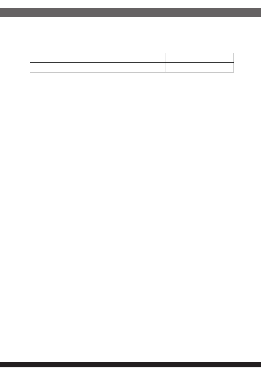
6.3.1 Sweep and resonance search for each of X,Y,Z, axis at the sweep.
RATE of 1/OCTAVE/Min.
6.3 Vibration and Shock
Frequency Duration Amplitude
5-55-10 Hz 30 minutes 0.35 mm
CE,FCC
8.1 Safety Requirement
cTUVus, CB,TUV
8.2 Leakage Current
The AC leakage current is less than 3.5mA when the power supply connect
to 264Vac/50Hz .
8.3 Insulation Resistance
The insulation resistance should be not less than 30M ohm after applying of
500VDC for 1 minute.
8.4 Dielectric Voltage Withstand
The power supply shall withstand for 1 minute without breakdown the
application of a 60Hz 1500V AC voltage applied between both input line and
chassis (20mA DC cut-off current). Main transformer shall similarly withstand
3000Vac applied between both primary and secondary windings for a
minimum of one minute.
7. Conducted EMI
8. Product Safety
A TTL compatible signal for the purpose of initiating an orderly start-up procedure
under normal input operating conditions. During power up, this signal is asserted
( low ) until +5V is under regulation and AC reaches min. line specification range.
After all voltage are going appropriate level, the system may have a turn on delay
of 100mS, but no greater than 250mS. During power off the signal should go to
low level before +5V is out of regulation. The low level is 0 to 0.8V and high level
is 4.75 to 5.25V. The " Power Good "signal can drive up to 6 standard TTL loads.
9. Power Good Signal
08
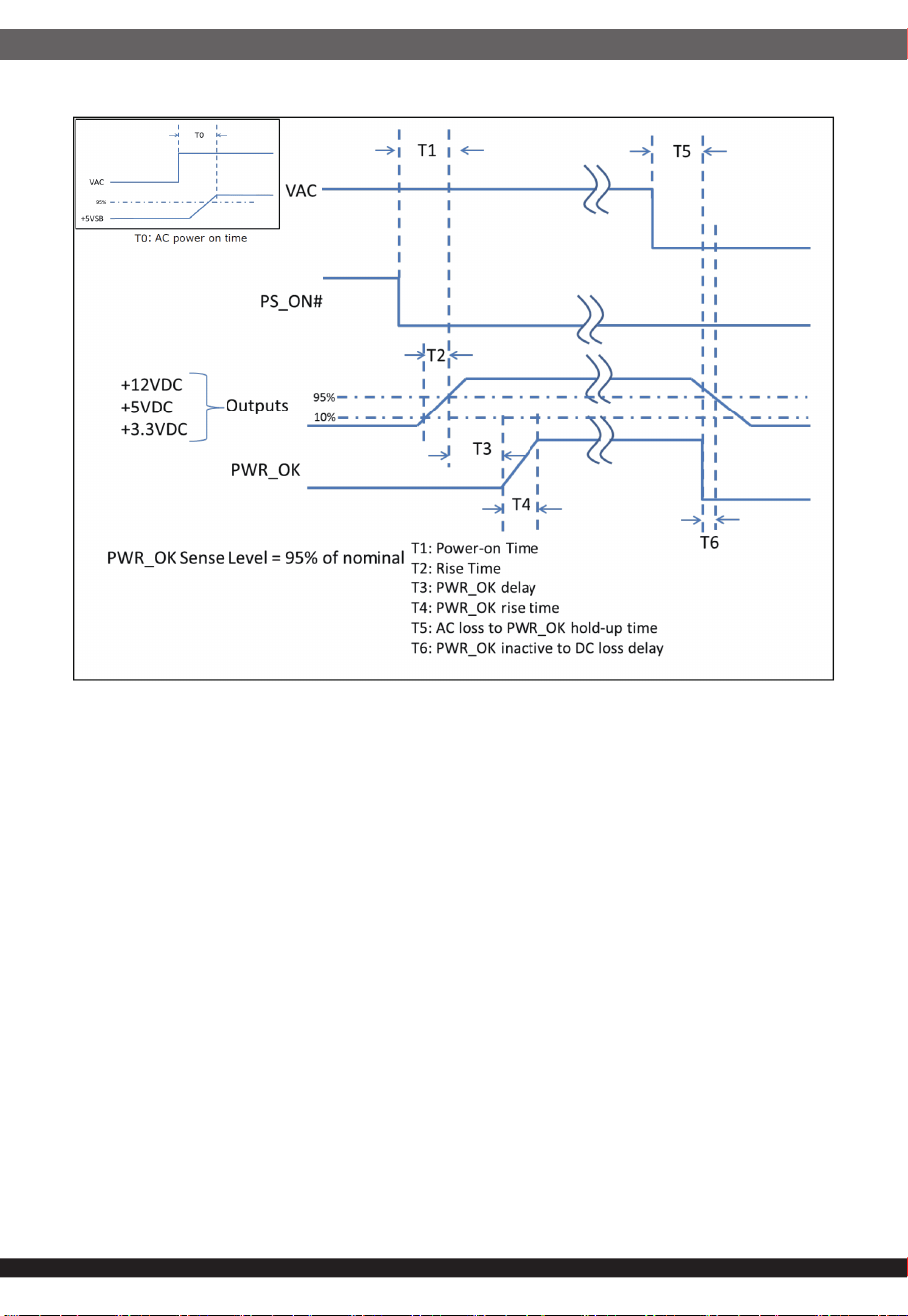
Figure 1 Time Diagram
* T0 : AC Turn on time ( 2S. Max.)
*T0: AC power on time (2S. Max)
T1 : Turn on time ( 200mS. Max.)
* T2 : Rise time ( 0.2~20 mS.)
* T3 : PWR_OK delay ( 100~ 250 mS )
* T4 : PWR_OK rise time (10mS. Max.)
* T5 : AC loss to PWR_OK hold-uptime (11mS Min )
* T6 : PWR_OK inactive to DC lossdelay (1 mS Min )
* Power on-off cycle :
When the power supply is turned off for a minimum of 2.0 sec. and turn on
again, the power good signal will be asserted.
The MTBF of the power should be 100,000 hours min.
10. MTBF
11.1 Input Voltage
Applying 230Vac .
11.2 Test Condition
Applying 80% loads for the power supply in 50 (+/-5) ℃ chamber for
4 hours.
11. Burn-In
09
The product shall meet requirement for EN61000-3-2 & EN61000-3-3 :2005
standard of class D, test at 230Vac 50Hz.
12. Harmonics
The power supply with active power factor correction, and meet the EN61000-3-2
standards, The power factor is greater than 0.95 at 230V/50Hz, Max. load.
13. Power Factor
1. The fan does not turn when the load is less than 330W, but the fan will start
to cool down when the temperature inside the machine exceeds the safe range.
2. when the load exceeds 330-495W, the fan starts.
3.Fan Delay Mode PS_ON# is turned off, the fan stops working 2 minute later.
14. Fanless Function
15.1 Outline Dimension
180 x 150 x 86.5 mm.
15.2 Weight
Maximum weight is 3.75Kg
15. Mechanical Specification
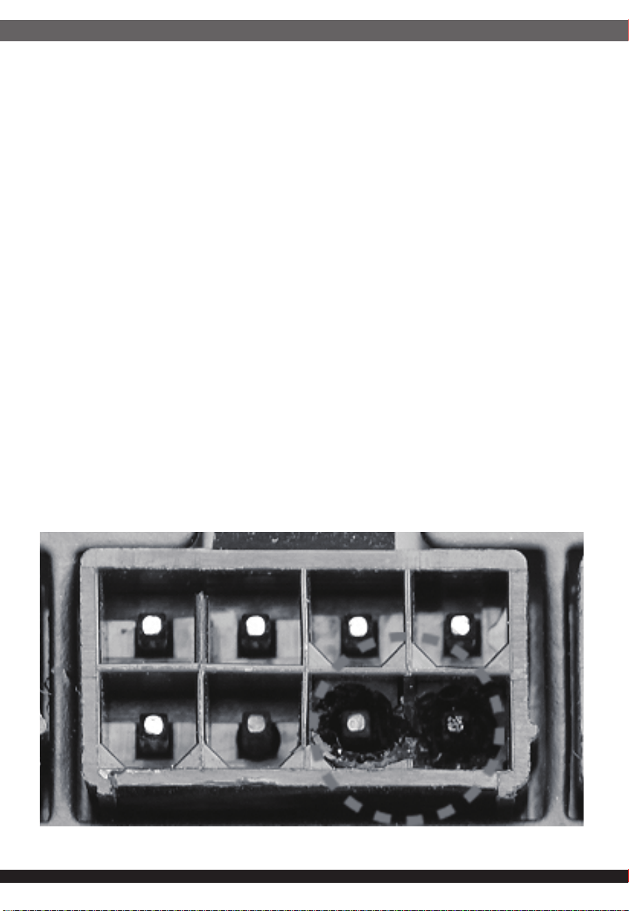
16. POWER SUPPLY CONNECTOR OVERUSE DEFINITION
10
Power supply connector overuse definition
EN
A single PCIe 8pin cable and connector’s maximum current rating is
12.5A, which is 150W (+12V x 12.5A). So SilverStone’s warranty will not
cover damages or malfunction resulting from the use of a graphics card
or expansion card with a single PCIe 8pin connector that exceeds
standard 225W total power draw (150W from PCIe 8pin connector +
75W from PCIe motherboard slot). Similarly, a graphics card or
expansion card with dual PCIe 8pin connectors that exceed 375W total
power draw (300W from two PCIe 8pin connectors + 75W from PCIe
motherboard slot) will also not be covered under warranty.
Peripheral (molex) or SATA connector’s maximum current rating is 5A,
which is 60W (+12V x 5A) or 25W (+5V x 5A). Please ensure connected
devices are operating under these limits. SilverStone’s warranty will not
cover damages or malfunction resulting from usages exceeding these
connectors and their associated cables.
24pin motherboard connector’s maximum current rating for its dual
+12V metal pins are 5A each, which totals 120W (+12V x 5A x 2).
Please ensure +12V drawing devices connected to the motherboard are
operating under these limits. SilverStone’s warranty will not cover
damages or malfunction resulting from usages exceeding these
connectors and their associated cables.
Definition einer Überlastung des
Netzanschlusses
DE
Die maximale Stromstärke eines einzelnen 8-poligen PCIe-Kabels und
Anschlusses beträgt 12,5 A, was 150 W (+12 V x 12,5 A) entspricht.
Daher deckt die SilverStone-Garantie keine Schäden oder
Fehlfunktionen durch den Einsatz einer Grafikkarte oder Erweiterung-
skarte mit einem einzigen 8-poligen PCIe-Anschluss ab, die die
Standardleistungsaufnahme von insgesamt 225 W übersteigt (150 W
vom 8-poligen PCIe-Anschluss + 75 W vom PCIe-Motherboard-Steck-
platz). Ebenso wird die Verwendung einer Grafikkarte oder
Erweiterungskarte mit zwei 8-poligen PCIe-Anschlüssen, die eine
Leistungsaufnahme von insgesamt 375 übersteigen (300 W von den
beiden 8-poligen PCIe-Anschlüssen + 75 W vom PCIe-Mother-
board-Steckplatz) nicht durch die Garantie abgedeckt.
Der maximale Nennstrom von Peripherie- (Molex) oder SATA-An-
schluss beträgt 5 A, was 60 W (+12 V x 5 A) oder 25 W (+5 V x 5 A)
entspricht. Bitte achten Sie darauf, dass verbundene Geräte unter
diesen Grenzwerten arbeiten. Die Garantie von SilverStone deckt keine
Schäden oder Fehlfunktionen aufgrund einer Nutzung ab, die diese
Anschlüsse und ihre zugehörigen Kabel übersteigt.
Der maximale Nennstrom des 24-poligen Motherboard-Anschlusses für
seine dualen +12-V-Metallkontakte beträgt jeweils 5 A, was insgesamt
120 W (+12 V x 5 A x 2) ergibt. Bitte stellen Sie sicher, dass mit dem
Motherboard verbundene +12-V-Geräte unter diesen Grenzwerten
arbeiten. SilverStones Garantie deckt keine Schäden oder
Fehlfunktionen aufgrund einer Nutzung jenseits der Angaben dieser
Anschlüsse und ihrer zugehörigen Kabel ab.
Définition de l'utilisation excessive du
connecteur d'alimentation électrique
FR
Le courant nominal maximum d'un périphérique (Molex) ou d'un
connecteur SATA est de 5 A, ce qui correspond à 60 W (+12 V x 5 A)
ou 25 W (+5 V x 5 A). Veuillez vous assurer que les appareils
connectés fonctionnent dans ces limites. La garantie de SilverStone
ne couvre pas les dommages ou les dysfonctionnements résultant
d'utilisations dépassant ces connecteurs et leurs câbles associés.
Le courant nominal maximal des connecteurs 24 broches de la carte
mère pour ses doubles broches métalliques +12 V est de 5 A chacun,
ce qui représente au total 120 W (+12 V x 5 A x 2). Veuillez vous
assurer que les dispositifs de tension +12 V connectés à la carte mère
fonctionnent dans ces limites. La garantie de SilverStone ne couvre
pas les dommages ou les dysfonctionnements résultant d'utilisations
dépassant la capacité de ces connecteurs et de leurs câbles
associés.
Le courant nominal maximum d'un câble et d'un connecteur PCIe 8
broches unique est de 12,5 A, ce qui correspond à 150 W (+12 V x
12,5 A). La garantie de SilverStone ne couvre donc pas les dommages
ou les dysfonctionnements résultant de l'utilisation d'une carte
graphique ou d'une carte d'extension avec un connecteur PCIe 8
broches unique qui dépasse une consommation énergétique totale de
225 W standard (150 W provenant du connecteur PCIe 8 broches + 75
W provenant de l'emplacement de la carte mère PCIe). De même, une
carte graphique ou une carte d'extension avec deux connecteurs PCIe
8 broches qui dépasse une consommation énergétique totale de 375 W
(300 W provenant des deux connecteurs PCIe 8 broches + 75 W
provenant de l'emplacement de la carte mère PCIe) ne sera également
pas couverte dans le cadre de la garantie.
La corrente massima di un singolo cavo PCIe a 8 pin e del connettore
è 12,5 A, corrispondente a 150 W (+12 V x 12,5 A). Pertanto, la
garanzia di SilverStone non copre danni o malfunzionamenti derivanti
dall'utilizzo di una scheda grafica o una scheda di espansione con un
singolo connettore PCIe a 8 pin che supera l'assorbimento totale di
225 W (150 W da connettore PCIe a 8 pin + 75 W da slot PCIe).
Analogamente, la garanzia non copre anche una scheda grafica o
una scheda di espansione con doppi connettori PCIe a 8 pin che
superano l'assorbimento totale di 375 W (300 W da doppi connettori
PCIe a 8 pin + 75 W dalla scheda madre PCIe).
La corrente massima del connettore periferico (molex) o SATA è 5 A,
corrispondente a 60 W (+12 V x 5 A) o 25 W (+5 V x 5 A). Assicurarsi
che i dispositivi collegati funzionino entro questi limiti. La garanzia di
SilverStone non copre danni o malfunzionamenti derivanti da uso
eccessivo di questi connettori e dei relativi cavi.
La corrente massima del connettore a 24 pin per scheda madre per i
suoi due pin di metallo a +12 V è di 5 A ciascuno, per un totale di 120
W (+12 V x 5 A x 2). Assicurarsi che i dispositivi a +12 V collegati alla
scheda madre funzionino con questi limiti. La garanzia di SilverStone
non copre danni o malfunzionamenti derivanti da uso eccessivo di
questi connettori e dei relativi cavi.
Definizione di uso eccessivo del connettore
di alimentazione
IT
Определение чрезмерной нагрузки на
коннектор блока питания
RU
Один кабель и коннектор PCIe 8pin поддерживает ток 12.5A, что
равно 150Вт (+12В x 12.5A). Таким образом, гарантийные
обязательства SilverStone не будут действовать если вы
используете видеокарту или другую карту расширения с одним
коннектором PCIe 8pin, которые превышает стандартную общую
потребляемую мощность 225Вт (150Вт через коннектор PCIe 8pin
+ 75Вт через слот PCIe материнской платы). Аналогично,
видеокарта или другая карта расширения с
двумя коннекторами
PCIe 8pin, которые превышают общую потребляемую мощность
375Вт (300Вт через коннектор PCIe 8pin + 75Вт через слот PCIe
материнской платы), также не будут покрываться гарантией.
Максимальный номинальный ток периферийного (molex) или
SATA разъёма составляет 5A, что равно 60Вт (+12В x 5A) или 25
Вт (+5В x 5A). Пожалуйста, убедитесь, что подключенные
устройства работают в этих пределах. Гарантия SilverStone не
будет распространяться на
неисправности, возникающие в
результате использования этих коннекторов или подключаемых к
ним кабелей.
Максимальный номинальный ток 24pin коннектора материнской
платы для его двойных металлических контактов +12В
составляет 5A на каждый, что равно 120Вт (+12В x 5A x 2).
Пожалуйста, убедитесь, что устройства, подключенные к линии
+12В, работают в этих пределах. Гарантия SilverStone не будет
распространяться на неисправности, возникающие
в результате
использования этих коннекторов или подключаемых к ним
кабелей.
11
전원 공급 커넥터 과용 정의
KR
埮沂穢ʹͺΖ穆理決挚愕珪嘫瘶汞牢堆洊幞洛冯汆Ͳ嵢昢
洊崫求嵢筞斶穞彺Έ·ΩͲ沋城埪΄ΚΝΧΖΣ΄ΥΠΟΖ汞
懺溣櫖昢垚祢渆Έ汞爣暒捊洊崫ʹͺΖ穆珪嘫瘶汞Έ歆
ʹͺΖ彚汾懺姢枲嵵汞Έ汞穯汊爎刂穞垚埮沂ʹͺΖ穆珪嘫瘶
痗沲勾岞穃獺姢喞筛沫獺姢庂斲殯穞櫲愢旣穞垚暖旇嬖垚
欪沗壟汊懺旇穞滆橐枻城埪決歆廎焲儆滆嵢Έ汞爣暒捊
洊崫ʹͺΖ穆珪嘫瘶儢汞Έ歆ʹͺΖ彚汾懺姢枲嵵汞Έ汞
穯汊爎刂穞垚姆櫂ʹͺΖ穆珪嘫瘶痗沲勾岞穃獺姢喞筛沫獺姢庂
斲殯空壊懺溣櫖昢懺旇空渂滆橐枻城埪
渂懆沫獞ΞΠΝΖΩ嬖垚΄Ͳ΅Ͳ珪嘫瘶汞牢堆洊幞洛冯汆Ͳ嵢昢
洊崫求嵢筞斶穞彺Έ·ΩͲ嬖垚Έ·ΩͲ沋城埪
櫶冶夢沫獞姪汆決峲穢洢穢穞櫖昢廒沗壟柢琢檂穯城埪΄ΚΝΧΖΣ΄ΥΠΟΖ
汞懺溣櫖昢垚決峲穢珪嘫瘶愕決歆櫶冶夞垚理決挚汞洛冯汊
爎刂穞櫲斲殯穮求嵢桮愢旣穞垚暖旇決喞欪沗壟汊懺旇穞滆
橐枻城埪
姆櫂·匎暓穆櫖斲殯夞垚穆彚汾懺姢珪嘫瘶汞洛冯洊幞垚
Ͳ決彶儇儇穯凊儆Έ·ΩͲΩ沋城埪彚汾懺姢櫖
櫶冶夢·沫獞儆空埿穢凊惾廒求嵢沗壟夞壊嵣穞柳柢欪
΄ΚΝΧΖΣ΄ΥΠΟΖ汆決珪嘫瘶喞分崮理決挚汞穢凊庂爎刂空昢
斲殯穮求嵢桮愢旣穞垚暖旇決喞処沫櫖堆空昢懺沫穞滆橐枻城埪
電力供給コネクタの使用限度超過に関する説明
JP
単一のPCIe8ピンケーブルおよびコネクタの最大定格電流は12.5Aで
150W(+12Vx12.5A)となります。それで定格225W合計電力消費(PCIe8
ピンコネクタからの150W+PCIeマザーボードスロットからの75W)を超
える、単一PCIe8ピンコネクタ装備のグラフィックスカードまたは拡張カ
ード使用によって生じた損傷や故障の場合、SilverStoneの製品保証は適
用外となります。同様に、375W合計電力消費(2基のPCIe8ピンコネクタ
からの300W+PCIeマザーボードスロットからの75W)を超える、デュア
ルPCIe8ピンコネクタ装備のグラフィックスカードまたは拡張カード使用
によって生じた損傷や故障の場合も、製品保証適用外となります。
周辺用(molex)またはSATAコネクタの最大定格電流は5Aで、60W
(+12Vx5A)または25W(+5Vx5A)となります。接続された装置がこれら
限度以内で動作することを確認してください。これらコネクタおよび関連
ケーブルの定格を超える使用法で生じた損傷や故障については、
SilverStone製品保証対象外となりますのでご注意ください。
24ピンマザーボードコネクタのデュアル+12V金属製ピンに対する最大
定格電流はそれぞれ5Aなので合計は120W(+12Vx5Ax2)となります。
接続される+12V入力のデバイスが、これら上限以内で動作することをご
確認ください。これらコネクタおよび関連ケーブルでの限界を超えた使
用で生じた損傷または故障は、SilverStoneによる製品保証対象外となり
ます。
ᴵ3&,HSLQ⬉⑤㒓Ϣ༈ⱘ᳔乱ᅮ⬉⌕Ў$ˈ⪺⡍᭄:
˄9[$˅DŽℸˈ䫊ⱘ⬉⑤ֱϡࣙᣀ⫼Ѣᴵ3&,H
SLQ༈Пᰒᠽܙˈ䍙䖛ޚ:ᘏࡳ㗫㣗ೈ᠔䗴៤ⱘᤳണ
ᬙ䱰˄:ⱘ3&,HSLQ༈:ⱘЏᵓ3&,Hᦦῑ˅DŽҹℸ㉏
ˈ㢹ঠ3&,HSLQ༈ⱘᰒᠽܙˈ䋳䕑ϔԚ䍙䖛:ᘏ
ࡳ㗫ˈ㾚ৠϡሲֱ㣗ೈݙ˄:ᴹ㞾ϸϾ3&,HSLQ༈:ⱘ
Џᵓ3&,Hᦦῑ˅DŽ
SLQ˄PROH[˅6$7$༈ⱘ᳔乱ᅮ⬉⌕Ў$ˈ:˄9[
$˅:˄9[$˅DŽ䇋⹂ֱ䖲ⱘ䆒ⱚԢѢℸ䰤ࠊϟ䖤㸠DŽ
䫊ϡֱ䍙ߎ⬉⑤կᑨ఼༈ঞ݊Ⳍ݇㒓ᴤПՓ⫼䋳䕑Ϟ䰤᠔䗴៤
ⱘᤳണᬙ䱰DŽ
SLQЏᵓ༈ⱘঠ9䞥ሲ䩜㛮᳔乱ᅮ⬉⌕Ў$ˈ:˄9
[$[˅DŽ䇋⹂ֱ䖲ⱘ9䆒ⱚԢѢℸ䰤ࠊϟ䖤㸠DŽ
䫊ϡֱ䍙ߎ⬉⑤կᑨ఼༈ঞ݊Ⳍ݇㒓ᴤПՓ⫼䋳䕑Ϟ䰤᠔䗴៤
ⱘᤳണᬙ䱰DŽ
⬉⑤կᑨ఼༈䖛ᑺՓ⫼ᅮН
CN
䳏⑤կឝ఼丁䘢ᑺՓ⫼ᅮ㕽
TW
ஂṱ3&,HSLQ䳏⑤㎮㟛丁ⱘ᳔両ᅮ䳏⌕⚎$ˈ⪺⡍ᭌ:˄
9[$˅DŽℸˈ䡔ⱘ䳏⑤ֱϡࣙᣀ⫼ᮐஂṱ3&,HSLQ
丁П乃ܙˈ䍙䘢῭⑪:㐑ࡳ㗫㆘ೡ᠔䗴៤ⱘ᧡າᬙ䱰˄
:ⱘ3&,HSLQ丁:ⱘЏ″ᵓ3&,Hᦦῑ˅DŽҹℸ串ˈ㢹
٭䲭3&,HSLQ丁ⱘ乃ܙˈ䉴䓝ϔԚ䍙䘢:㐑ࡳ㗫ˈ㽪ৠ
ϡቀֱ㆘ೡܻ˄:՚㞾ܽן3&,HSLQ丁:ⱘЏ″ᵓ3&,Hᦦ
ῑ˅DŽ
SLQ˄PROH[˅6$7$丁ⱘ᳔両ᅮ䳏⌕⚎$ˈ:˄9[
$˅:˄9[$˅DŽ䂟⺎ֱ䗷ⱘ䀁٭ⱚԢᮐℸ䰤ࠊϟ䘟㸠DŽ
䡔ϡֱ䍙ߎ䳏⑤կឝ఼丁ঞ݊Ⳍ䮰㎮ᴤПՓ⫼䉴䓝Ϟ䰤᠔䗴៤
ⱘ᧡າᬙ䱰DŽ
SLQЏ″ᵓ丁ⱘ䲭9䞥ቀ䞱㝇᳔両ᅮ䳏⌕⚎$ˈ:˄
9[$[˅DŽ䂟⺎ֱ䗷ⱘ9䀁٭ⱚԢᮐℸ䰤ࠊϟ䘟㸠DŽ
䡔ϡֱ䍙ߎ䳏⑤կឝ఼丁ঞ݊Ⳍ䮰㎮ᴤПՓ⫼䉴䓝Ϟ䰤᠔䗴៤
ⱘ᧡າᬙ䱰DŽ
ขีดจำกัดการรองรับการใช้งานของขั้วต่อจากพาวเวอร์ซัพพลาย
TH
สำหรับขั้วเชื่อมต่อและสายไฟเลี้ยง PCIe 8 พินสามารถรองรับกระแสได้สูงสุด 12.5
แอมป์หรือหมายถึง 150 วัตต์
(+12V x 12.5A) ดังนั้นการรับประกันจากทาง SilverStone จะไม่ครอบคลุมถึงความ
เสียหายหรือความผิดปรกติซึ่งเกิดขึ้นกับกราฟิกการ์ดรวมถึงการ์ดขยายความยาวที่ใช้งาน
ขั้วเชื่อมต่อ PCIe 8 พิน ซึ่งมันมีการใช้พลังงานรวมทั้งสิ้นเกินกว่ามาตรฐานที่กำหนดคือ
225 วัตต์ (150 วัตต์ จาก PCIe 8 พิน + 75 วัตต์ จากสล๊อต PCIe บน
เมนบอร์ด) อันรวมถึงกราฟิการ์ดหรือการ์ดขยายความยาวที่ใช้ขั้วต่อไฟเลี้ยง PCIe 8
พินจำนวน 2 ชุดซึ่งมีการใช้พลังงานทั้งสิ้น 375 วัตต์ (300 วัตต์ จากขั้ว PCIe 8
พิน 2 ชุด + 75 วัตต์ จากสล๊อต PCIe บนเมนบอร์ด) ซึ่งไม่ครอบคลุมเช่นกัน
ภายใต้การรับประกัน ขั้วเชื่อมต่อ Peripheral หรือ Molex 4 พินและ SATA มันสามารถ
รองรับกระแสได้สูงสุด 5 แอมป์หรือหมายถึง 60 วัตต์ (+12V x 5A) หรือ (+5V
+ 5A) กรุณาให้แน่ใจว่าอุปกรณ์ที่ใช้งานมีการใช้พลังงานไม่เกินกว่าขีดจำกัดที
่รองรับ ดัง
นั้นการรับประกันจากทาง SilverStone จะไม่ครอบคลุมถึงความเสียหายหรือความผิด
ปรกติจากอุปกรณ์ที่เชื่อมต่อใช้งานจากตัวสายเชื่อมต่อซึ่งมีการใช้พลังงานเกินกว่าขีด
จำกัด
กระแสไฟฟ้าสูงสุดของขั้วต่อเมนบอร์ด 24 พิน สำหรับพินโลหะ +12V คู่แต่ละอันมีค่า
5A ซึ่งรวมทั้งหมดเป็น 120W
(+12V x 5A x 2) โปรดตรวจสอบให้มั่นใจว่าอุปกรณ์ตัวดึงพลังงาน +12V ที่เชื่อม
ต่อกับเมนบอร์ดสามารถทำงานภายใต้ขีดจำกัดเหล่านี้ได้ การรับประกันของ SilverStone
ไม่คุ้มครองความเสียหาย หรืออาการเสียที่เป็นผลจากการใช้เกินขีดจำกัดของขั้วต่อและสาย
เคเบิลที่ใช้เชื่อมต่อเหล่านี้
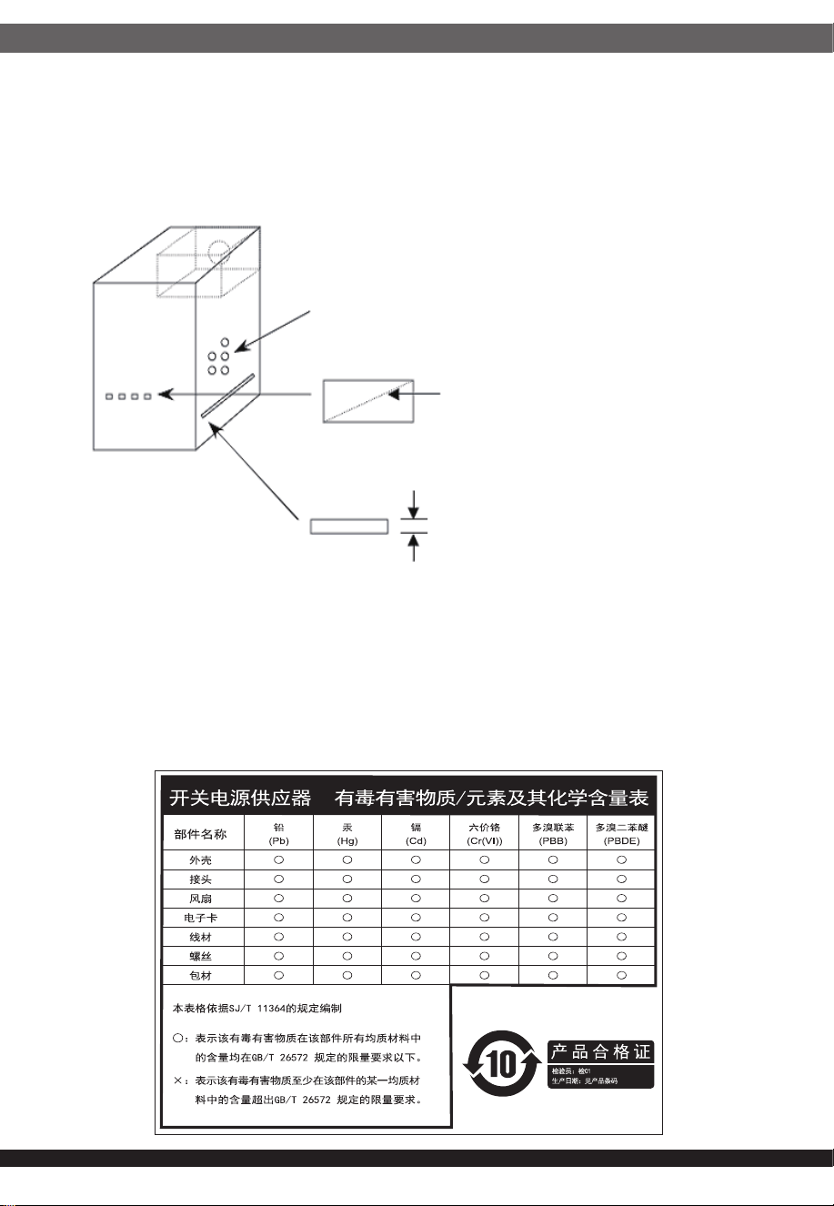
⚎њֱ䅋Փ⫼㗙ঞ䰆☿ⱘⳂⱘˈᅝ㺱ℸѸᓣ䳏⑤կឝ఼ᰖˈᖙ䷜ᅝ㺱ᮐヺড়ϟ߫䷙㽕∖ⱘ←Ёˈ
ϺϨᅝ㺱ཹᕠˈᠡৃϞ䳏⑤DŽ
←ᴤ䊾䷜⚎䰆☿←DŽᴤ䋼乏Ў䰆☿DŽ
←ⱘϞᮍঞو䙞П೧ᔶ䭟ᄨˈ᳔ܻᕥϡৃᮐPPDŽ
←ⱘϞᮍঞو䙞П䭋ṱൟ䭟ᄨˈᇡ㾦㎮䎱䲶ϡৃᮐPP˗㢹ᇀᑺᇣᮐPPˈࠛ䭋ᑺϡফ䰤ࠊDŽ
←ᑩ䚼ϡৃ᳝䭟ᄨDŽᑩ䚼ϡৃ᳝ᓔᄨDŽ
ⳈᕥϡᮐPP
ᇡ㾦㎮ϡᮐPP
ᇀᑺᇣᮐPPࠛ䭋ᑺϡ䰤
Openings that do not exceed 1mm in width regardless of length
Openings that do not exceed 5mm in any dimension
ᴀ⫶ક䔌ߎ᳝䱾㛑䞣ˈ⚎䙓ܡ᪡ᰖⱐ⫳䱾ˈ䷜ᮐ㺱ܹ㋏㍅″←Ϻᇛ᠔᳝䀁٭ᅝ㺱ཹ⭊ᕠᠡৃ䭟ଳ䳏⑤DŽ
ᴀ⫶કП䳏⑤䔌ߎ䴲ቀ䳏䰤ࠊൟ䳏⑤ˈ䂟䗷Փ⫼䰆☿←П䙞ˈҹ䙓ܡ☿♑䱾ⱐ⫳DŽ
%60,52+6䊛㿞
KWWSZZZVLOYHUVWRQHWHNFRPGRZQORDGV36856'SGI

13
This device complies with Part 15 of the FCC Rules.
Operation is subject to the following two conditions:
(1) this device may not cause harmful interference, and
(2) this device must accept any interference received,
including interference that may cause undesired operation.
Please refer to SilverStone website for latest specifications updates.
※付属の電源コードは当該製品専用です。他の機器に使用しないでください。
・本製品は1650Wの出力が可能な高出力電源となります。
・100V環境の場合、1650Wの出力を行う場合には19A前後の電流が必要となるため、
20Aを許容する環境にてご利用ください。
・一般家庭のコンセント(1500W)の場合は、1300W未満の消費電力でご利用ください。
・日本国内向けに販売されている本製品の付属電源ケーブルは100V(最大15A)専用となります。
・本製品に200V用電源ケーブル、および100V/20A用電源ケーブルの同梱はございません。
・100V/15A以外の環境でご利用の際は、安全の為、必要な電源ケーブルを別途ご用意ください。
Model (on safety)
: SST-AX1650MCPT-A
NO. G11251540