Quick Start Guide
Visit www.tapo.com/support
for technical support, user guides, warranty,
and more information
?
7100001457 REV1.0.2 © 2025 TP-Link
Smart Wi-Fi Door Lock
Welcome to Tapo!
Installation Guide & Video
Scan QR code or visit
https://www.tp-link.com/support/faq/4335/
Our expert Technical Support team is ready to assist you.
Please don't hesitate to reach out with any questions.
Contact Us
CALL
+1 866 225 8139 (Toll-Free)
EMAIL
CHAT
https://livechat.tp-link.com/us
For United States
https://www.tp-link.com/support/
contact-technical-support/
CALLEMAIL
CHAT
For Other Countries/Regions

1
5
8
20
22
Parts in the Box
Installation Preparation
Installation
Setup
What if the battery is dead
while you are outside?
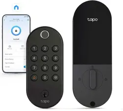
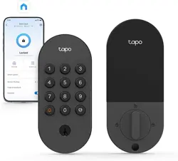
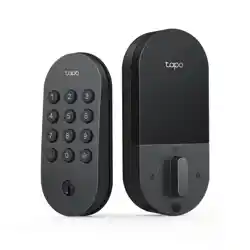
Appearance
23
24
How to set the PIN code
Contents
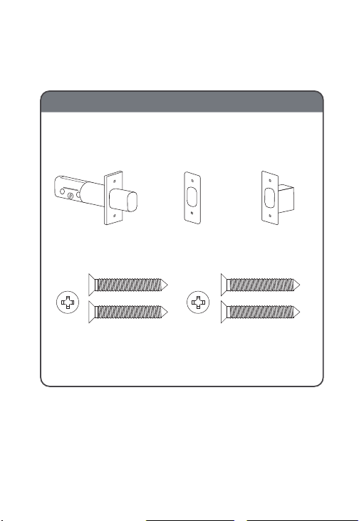
Parts in the Box
1
Bolt Strike Plate Dust Box
Bolt Screws
(ST4*25)×2
Strike Plate Screws
(ST4*25)×2
Packaged Together
Install the Bolt & Strike Plate
TOP
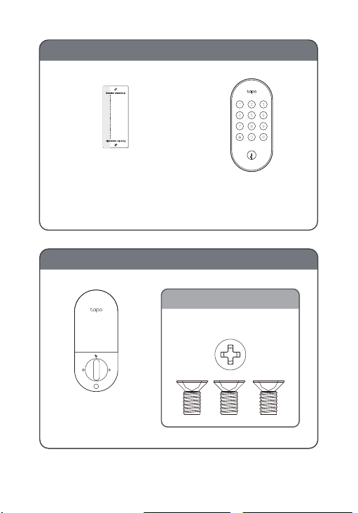
Actual Size
(M4*7.5)×3
2
Install Exterior Assembly
Installation
Reference Line
Sticker for
Exterior Assembly
Install Interior Assembly
Interior
Assembly
Exterior
Assembly
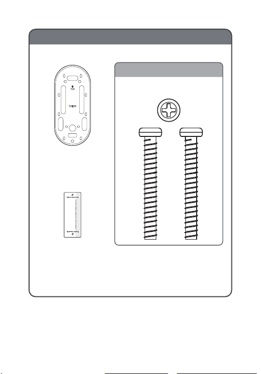
Installation
Reference Line
Sticker for Interior
Assembly
Mounting
Plate
Actual Size
(M4*32)×2
3
Install the Interior Mounting Plate
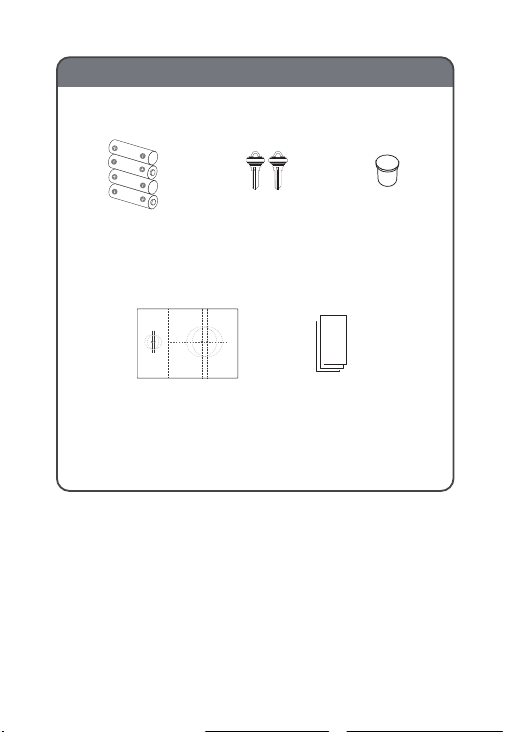
Keys ×2 Silicone
Cover
AA/LR6
Batteries ×4
Quick Start
Guide
Measuring
Template
guide
4
Others

Installation
Preparation
5
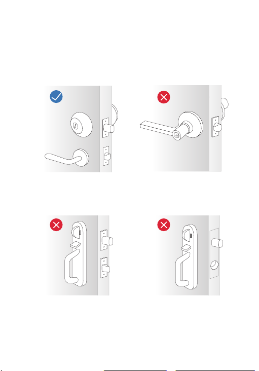
Compatible with Single
Cylinder Deadbolt
Lever Handle Lock Not
Compatible
Integrated Locks
Not Compatible
Mortise Locks
Not Compatible
Check Compatibility
1. Check your existing door lock type.
6
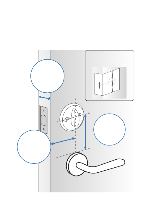
2. Measure your door.
Place the measuring template on the door,
aligning its door edge line with the door
edge.
7
Door
Thickness
1-3/8’’ to
2-11/64’’
(35-55 mm)
Minimum
Distance
1-37/64’’ (40
mm)
Backset
2-3/8’’ (60 mm)
or 2-3/4’’ (70
mm)
Align the template
with the door edge.

Installation
8
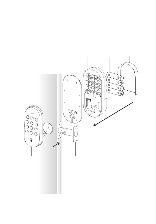
Installation Overview
9
1
[Door]
TOP
Mounting
Plate
Exterior
Assembly
Bolt
Batteries
Interior
Assembly
Battery
Cover
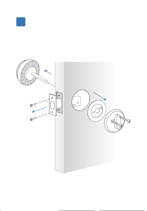
10
Remove your existing lock.
1
Remove your existing door lock and bolt.
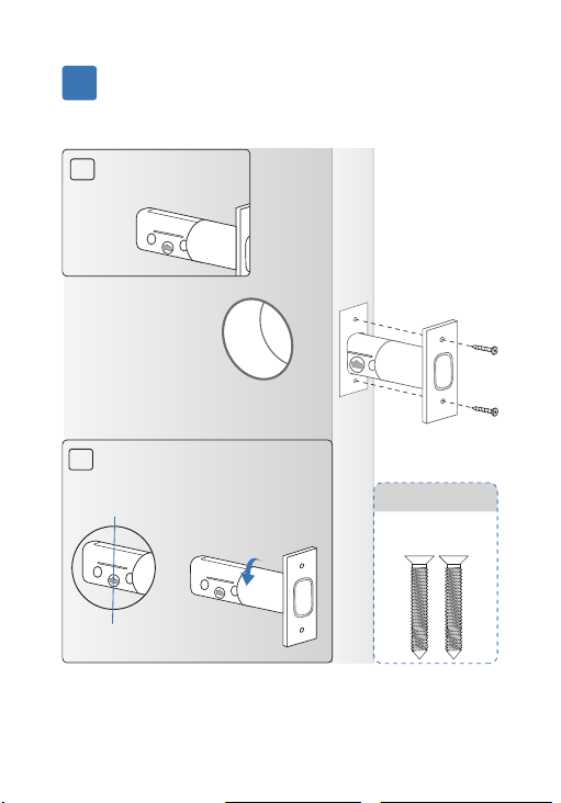
11
Install the new bolt.
2
TOP
TOP
TOP
A
Ensure the word
TOP is facing up.
B
If the latch hub is not
centered in the door hole,
twist the bolt to extend it.
TOP
Center
Line
Packaged together
with the bolt
Bolt Screws
Twist to
extend
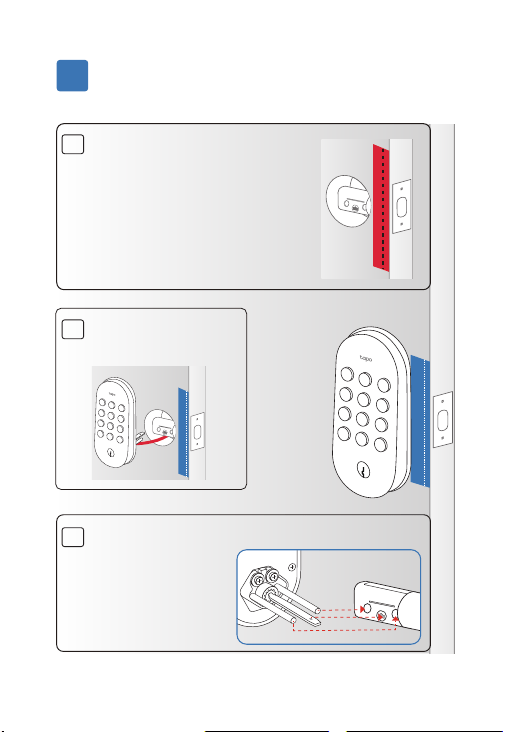
1
Install the exterior assembly.
3
12
TOP
A
Place the exterior assembly
sticker on the outside door
by aligning its door edge
line with the door’s edge.
Note: Choose the door
edge line based on your
backset distance.
TOP
[OUTSIDE]
B
Cable goes under
the bolt.
TOP
C
Insert the tailpiece and two prongs into the
TOP
corresponding
holes on the bolt
and align the
exterior assembly
with the sticker.
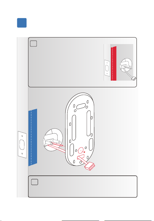
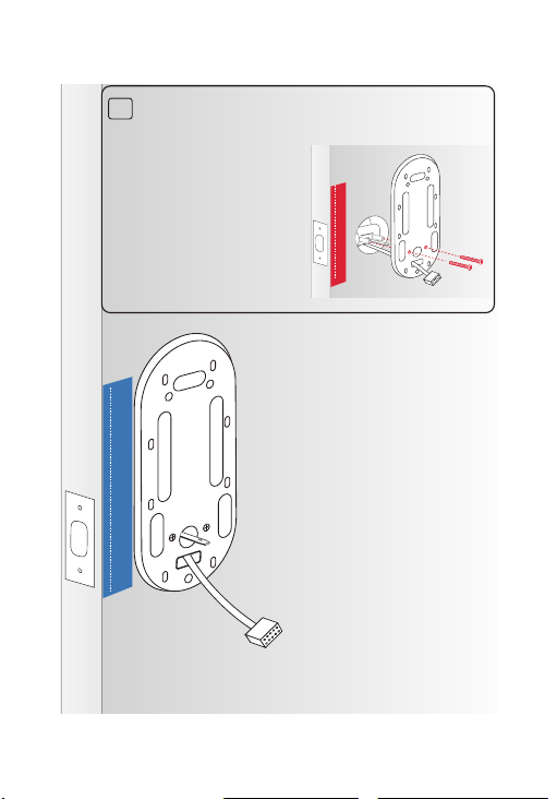
Install the mounting plate.
4
13
TOP
A
Place the interior assembly
sticker on the inside door
by aligning its door edge
line with the door’s edge.
Note: Choose the door
edge line based on your
backset distance.
TOP
Route the cable through the mounting
plate’s rectangular hole and insert the
tailpiece into the center round hole.
B
14
C
Align the mounting plate with the sticker,
ensuring the two prongs of the exterior
TOP
assembly match
the two holes next
to the center round
hole.
Secure it with the
screws.
15
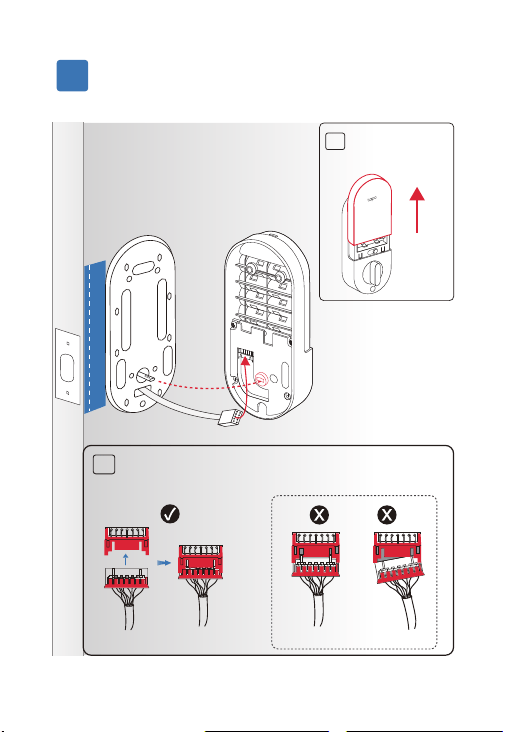
Install the interior assembly.
5
B
Connect the cable tightly. Ensure the color
side faces up.
Not tightly connected
Red marking facing up
[INSIDE]
A
Remove the
battery cover.
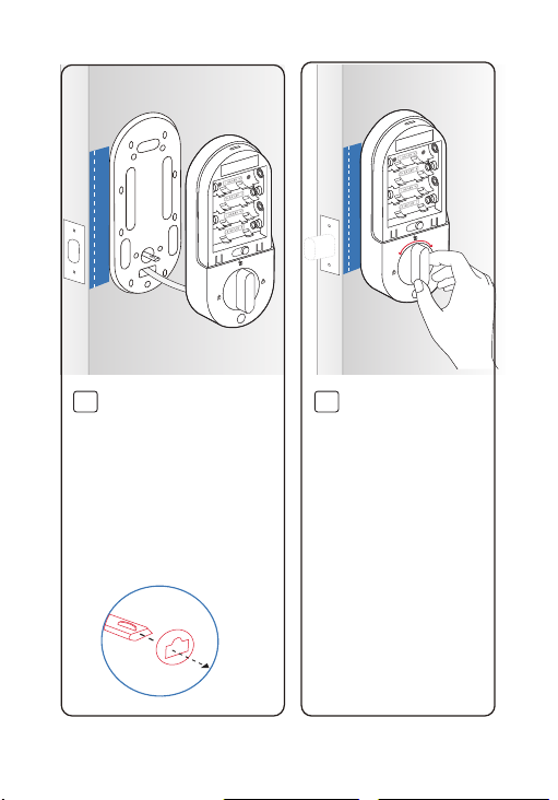
Reset
16
C
Align the tailpiece with
the thumb-latch slot. You
can rotate the thumb
latch to adjust the slot.
Attach the interior
assembly to the
mounting plate.
D
Rotate the thumb
latch to ensure the
latch retracts
normally.
Reset
Reset
17
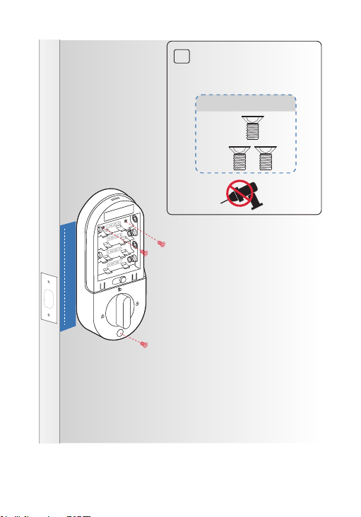
E
Use the three provided
M4*7.5 screws to ax
the interior assembly.
M4*7.5 Screws
Reset
18
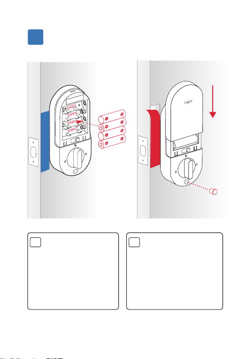
Install the batteries.
6
A
Insert the batteries
into the interior
assembly, ensuring
the positive and
negative terminals
are oriented
correctly.
B
Replace the cover by
sliding it down. Insert
the silicone cover
into the bottom hole.
Remove the stickers.
Reset
Reset
19
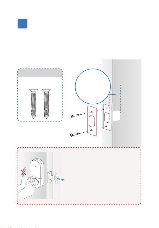
Install the dust box & strike plate.
7
Insert the dust box and strike plate into the
strike hole on the door frame and secure with
screws. Ensure the depth of the strike hole is at
least 1’’ (25.4 mm).
Strike Hole
Depth
1’’ (25.4 mm)
[Frame]
If the bolt operates smoothly
without pushing or pulling the
door, you can use your original
strike plate.
If you need to push or pull the
door for smooth operation,
adjust the strike plate's position
on the door frame.
Packaged together
with the bolt
Strike Plate Screws

Setup
20
21
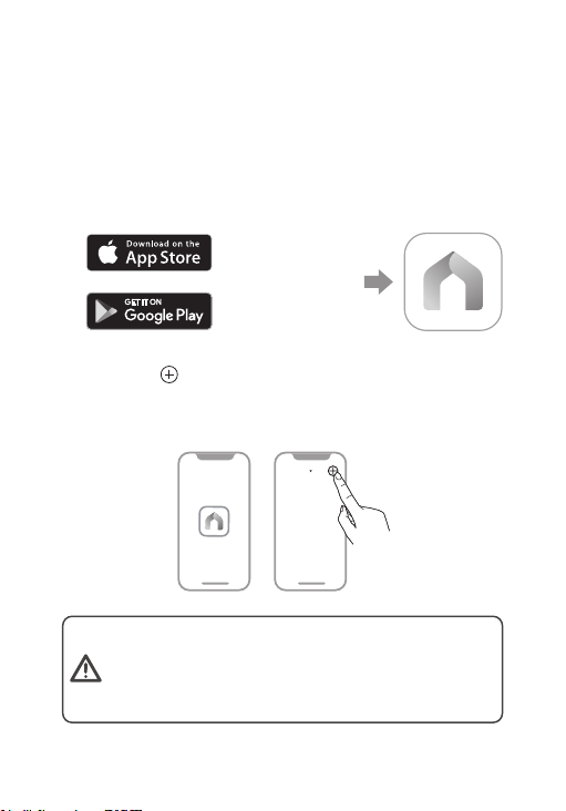
2. Tap the button in the app. Select Door
Locks and then your model. Follow the app
instructions to complete setup.
1. Get the Tapo app from the App Store or
Google Play and log in with your TP-Link ID. If
you do not have an account, create one rst.
OR
Set Up Your Lock
My Home
The Tapo app is needed to use this lock. If this
lock was professionally installed (or installed by
someone other than the homeowner), make sure
this step was performed by the homeowner.
22
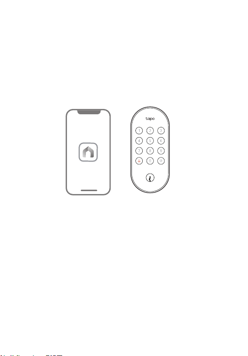
How to set the PIN code
The PIN code should be set in the Tapo app.
Tapo will guide you to set your access code.
Tapo
23
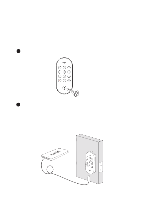
What if the battery is dead
while you are outside?
Connect to a power outlet or power bank using a
USB cable to provide a temporary power supply.
Note that this port is for power only and cannot
transfer data.
Unlock via the provided key
Temporarily power up the lock
5V

Appearance
24
25
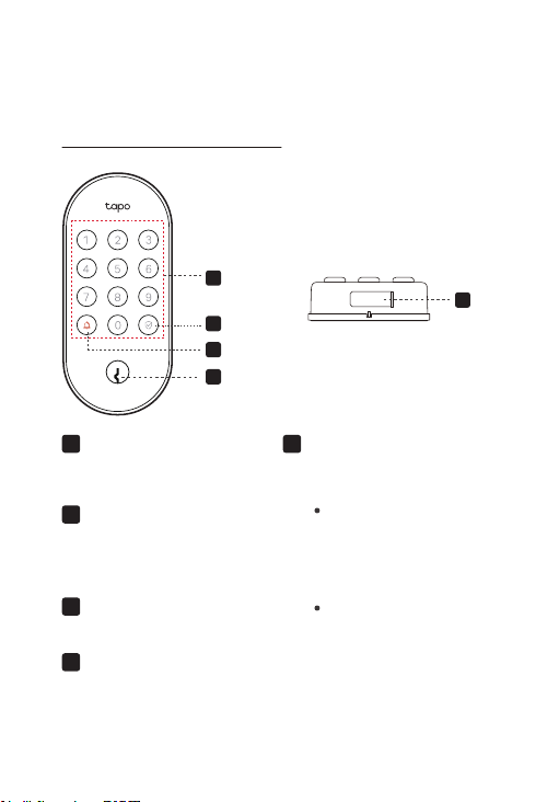
Appearance
1
2
3
4
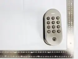
Exterior Assembly
1
Keypad
Lock/unlock the door by
entering your PIN code.
3 Ring Button
When this button is pressed,
you will receive notications
in the app.
5 5V Type-C Port
Connect to a power outlet for
a temporary power supply.
4
Lock Cylinder
Unlock via the provided keys.
2
When entering the PIN
code starting with
scrambled digits, press
this button to conrm
unlocking.
When the door is
unlocked, press this
button to lock it.
Indicates the lock/unlock
status and device status.
Button:
Indicator:
Lock/Unlock Button &
Indicator
5
26
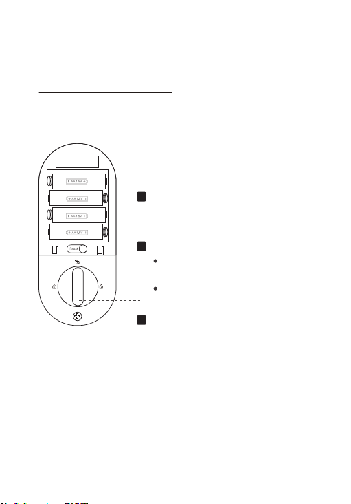
Interior Assembly
Thumb Latch
Rotate to lock/unlock the door.
Battery Compartment
Insert the provided batteries to
power your lock.
Reset
Press and hold for 5s to reset
Wi-Fi settings.
Press and hold for 10s to factory
reset your device.
1
2
3
27
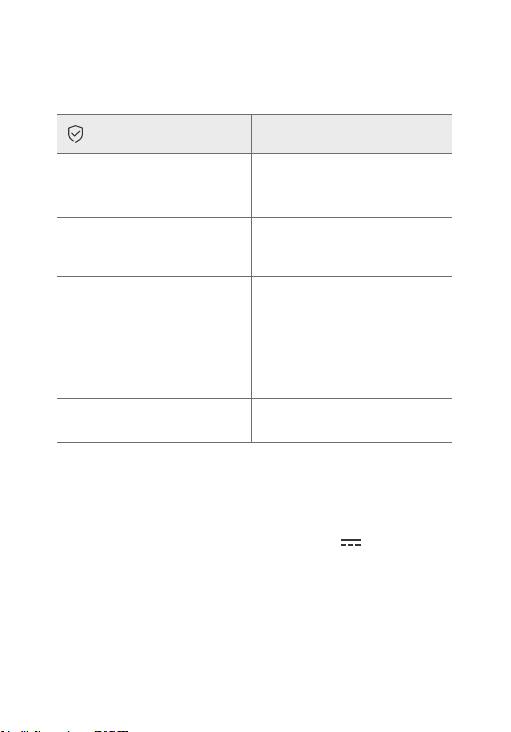
Lock/Unlock Indicator
Specications
Solid red
Solid yellow
Indicator Display
Solid blue
Blinking red and green
Type-C Emergency Power Supply: 5V
Batteries: 4× 1.5V SIZE AA/LR6
Rainproof Rating: IP54 (only for the exterior assembly)
Situation
Locking/unlocking failed
Being locked;
Locking successful
Being unlocked;
Unlocking successful
Ready for setup
Too many PIN code
attempts
Door lock jammed;
28
• Do not attempt to disassemble, repair, or modify the device. If you need
service, please contact us.
• Do not use the device where wireless devices are not allowed.
• Keep the device away from water, re, humidity or hot environments.
• Do not place near automatically controlled devices such as re alarms. Radio
waves emitted from this product may cause such devices to malfunction
resulting in an accident.
• Observe restrictions on using wireless products in fuel depots, chemical
plants or when blasting operations are in progress.
• Never put metal objects inside the product. If a metal object enters the
product turn o the circuit breaker and contact an authorised electrician.
• This product is not intended to be used when providing medical care. Consult
the manufacturer of any personal medical devices, such as pacemakers or
hearing aids to determine if they are adequality shielded from external RF
(radio frequency) energy.
• Do not use this product in health care facilities. Hospitals or health care
facilities may be using equipment that could be sensitive to external RF
energy.
• Ensure to use a power bank or 5V power adapters when temporarily powering
up the device.
• When the interior room temperature is below 0°C, the device may not be
unlocked using PIN codes due to the limited battery discharge capacity of
AA/LR6 Alkaline batteries.
• Exterior Assembly Operating Temperature: -30 °C ~ 70°C (-22°F ~ 158°F)
Please read and follow the above safety information when operating the device.
We cannot guarantee that no accidents or damage will occur due to improper
use of the device. Please use this product with care and operate at your own
risk.
Safety Information
CAUTION!
Avoid replacement of a battery with an incorrect type that can defeat a
safeguard. Avoid disposal of a battery into re or a hot oven, or mechanically
crushing or cutting of a battery, that can result in an explosion. Do not leave
a battery in an extremely high temperature surrounding environment that
can result in an explosion or the leakage of ammable liquid or gas. Do not
leave a battery subjected to extremely low air pressure that may result in an
explosion or the leakage of ammable liquid or gas.
CAUTION!
Risk of re or explosion if the battery is replaced by an incorrect type
19

FCC Statement
This equipment has been tested and found to comply with the limits for a
Class B digital device, pursuant to part 15 of the FCC Rules. These limits
are designed to provide reasonable protection against harmful interference
in a residential installation. This equipment generates, uses and can radiate
radio frequency energy and, if not installed and used in accordance with the
instructions, may cause harmful interference to radio communications.
However, there is no guarantee that interference will not occur in a
particular installation. If this equipment does cause harmful interference to
radio or television reception, which can be determined by turning the
equipment off and on, the user is encouraged to try to correct the
interference by one or more of the following measures:
—Reorient or relocate the receiving antenna.
—Increase the separation between the equipment and receiver.
—Connect the equipment into an outlet on a circuit different from that to
which the receiver is connected.
—Consult the dealer or an experienced radio/TV technician for help.
FCC Radiation Exposure Statement
This device complies with FCC radiation exposure limits set forth for an
uncontrolled environment and it also complies with Part 15 of the FCC RF
Rules. This equipment must be installed and operated in accordance with
provided instructions and the antenna(s) used for this transmitter must be
installed to provide a separation distance of at least 20 cm from all persons
and must not be co-located or operating in conjunction with any other
antenna or transmitter. End-users and installers must be provided with
antenna installation instructions and consider removing the no-collocation
statement.
This device complies with Part 15 of the FCC Rules. Operation is subject to
the following two conditions:
(1) this device may not cause harmful interference, and
(2) this device must accept any interference received, including interference
that may cause undesired operation.
Caution!
Any changes or modifications not expressly approved by the party
responsible for compliance could void the user's authority to operate the
equipment.
29

Canadian Compliance Statement
This device contains licence-exempt transmitter(s)/receiver(s) that comply
with Innovation, Science and Economic Development Canada’s licence-
exempt RSS(s). Operation is subject to the following two conditions:
(1) This device may not cause interference.
(2) This device must accept any interference, including interference that
may cause undesired operation of the device.
L’émetteur/récepteur exempt de licence contenu dans le présent appareil
est conforme aux CNR d’Innovation, Sciences et Développement
économique Canada applicables aux appareils radio exempts de licence.
L’exploitation est autorisée aux deux conditions suivantes :
1) L’appareil ne doit pas produire de brouillage;
2) L’appareil doit accepter tout brouillage radioélectrique subi, même si le
brouillage est susceptible d’en compromettre le fonctionnement.
Radiation Exposure Statement:
This equipment complies with IC radiation exposure limits set forth for an
uncontrolled environment. This equipment should be installed and operated
with minimum distance 20cm between the radiator & your body.
Déclaration d'exposition aux radiations:
Cet équipement est conforme aux limites d'exposition aux rayonnements IC
établies pour un environnement non contrôlé. Cet équipement doit être
installé et utilisé avec un minimum de 20 cm de distance entre la source de
rayonnement et votre corps.
Industry Canada Statement
CAN ICES-003 (B)/NMB-003(B)
30