
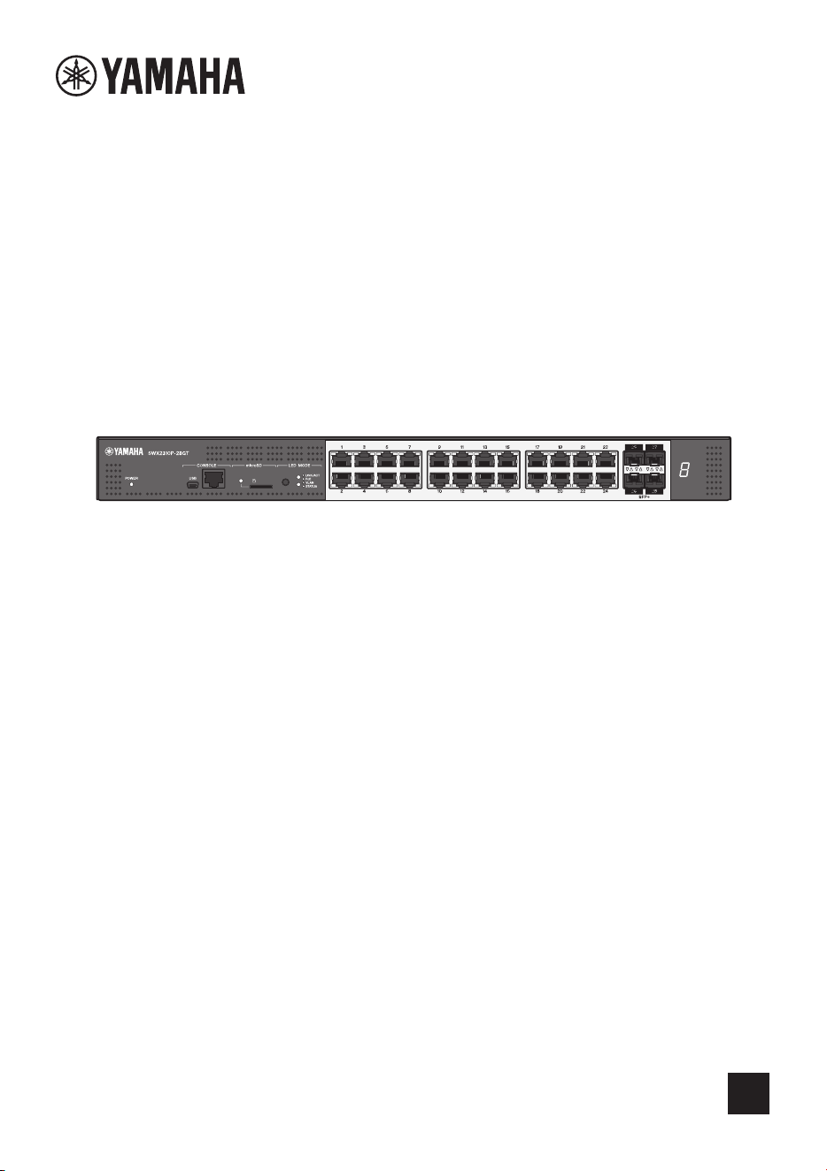
L2 Switch
SWX2310P-28GT
EN
Getting Started Guide

2 SWX2310P-28GT Getting Started Guide
Contents
Introduction .................................................................................................3
Product features ................................................................................................. 3
Notation conventions in this document ..............................................................3
Abbreviations ........................................................................................... 3
Trademarks ..............................................................................................3
Symbols used in this guide ...................................................................... 3
Included items....................................................................................................4
Separately sold items.........................................................................................5
Controls and connectors............................................................................6
Front panel ......................................................................................................... 6
Bottom, rear, top, and side panels...................................................................... 8
Bottom panel............................................................................................8
Rear panel ...............................................................................................9
Top panel ............................................................................................... 10
Side panel.............................................................................................. 10
Switching between display modes ................................................................... 11
Port indicators .................................................................................................. 12
Installation .................................................................................................15
Installing the product horizontally........................................................... 15
Installing the product in a 19-inch rack................................................... 15
Settings ......................................................................................................17
Using the CONSOLE port to specify settings from the command line............. 18
Using Telnet to specify settings from the command line ..................................21
Using SSH to specify settings from the command line .................................... 23
Using the Web GUI to specify settings............................................................. 25
Restoring product settings to default factory values ......................................... 26
Connections ..............................................................................................29
Connecting to a network device or computer......................................... 29
Connecting to a PoE-powered device....................................................29
Installing an SFP module.......................................................................30
Removing an SFP module..................................................................... 30
Installing a direct attachment cable........................................................31
Removing a direct attachment cable......................................................31
Configuring stack connections ............................................................... 32
Connecting the power cord .................................................................... 33
Appendix....................................................................................................34
Hardware specifications ................................................................................... 34
Introduction
SWX2310P-28GT Getting Started Guide
3
Introduction
The SWX2310P-28GT intelligent L2 switch is an L2 PoE switch that is ideal for installing PoE-
powered devices in a medium-scale network. It supports supplying up to 30 W of
IEEE802.3at (PoE+) power per port and enables easy configuration of Dante or other ProAV
profiles. That means it can be used as a switch for installing ProAV devices, such as PoE-
driven speakers, microphones, or cameras.
° Abbreviations
Company names and product names in this document are abbreviated as follows.
• Yamaha SWX2310P-28GT L2 switch: “this product” or “the product”
• 10BASE-T, 100BASE-TX, and 1000BASE Ethernet cable: “LAN cable”
° Trademarks
• Microsoft and Windows are registered trademarks of Microsoft Corporation (USA) in the
USA and other countries.
• Other company names and product names indicated in this document are registered
trademarks or trademarks of their respective corporate owners.
° Symbols used in this guide
Refers to a situation that poses the risk of death or serious injury to the user.
Refers to a situation that poses the risk of injury to the user.
Indicates information that requires user compliance in order to avoid product failure, dam-
age, malfunction, or loss of data.
Indicates information that the user must know to properly operate and use this product.
NOTE
Refers to information regarding the operation and use of this product. Read this for your
reference.
Product features
Notation conventions in this document
WARNING
CAUTION
NOTICE
IMPORTANT

Introduction
4 SWX2310P-28GT Getting Started Guide
Verify that the following items are included.
• Read This First: 1 pc.
• Power cords: 2 pcs. (use an appropriate power cord for your regional power supply.)
• Power cord clamp: 1 pc. (used only for the included dedicated power cord)
• Dust covers (pre-installed on the SFP+ slots when the product is shipped): 4 pcs.
• Legs (rubber feet): 4 pcs.
• 19-inch rack mount hardware: 2 pcs.
• Screws (M3 x 10L): 8 pcs.
• The purpose of this guide is to provide information necessary for using basic prod-
uct functionality.
In addition to this guide, the following manuals are also available for respective
product use scenarios. Refer to the manual appropriate for the given purpose for
using the manual.
• Read This First (included in packaging)
Indicates various precautions about using the product. Read this document before
using the product.
• Command Reference (Website)
Lists the format of commands used to configure settings for this product and gives
examples of using the commands. Refer to the information page for this product on
the Yamaha website.
• Technical Data (Website)
Provides detailed information about product functionality. Refer to the information
page for this product on the Yamaha website.
• Help Pages for Configuring Web GUI Settings
This lists detailed explanations of each parameter in the settings.
• Copying or otherwise reproducing this guide, in whole or in part, is expressly forbid-
den without the written consent of Yamaha.
• The explanations in this guide are based on product specifications current as of the
publication date. The latest version can be downloaded from the Yamaha website.
• Yamaha accepts no responsibility for lost data or other damages that result from
using the product. The warranty scope is limited to damage to the product. Thank
you in advance for your understanding.
Included items

Introduction
SWX2310P-28GT Getting Started Guide
5
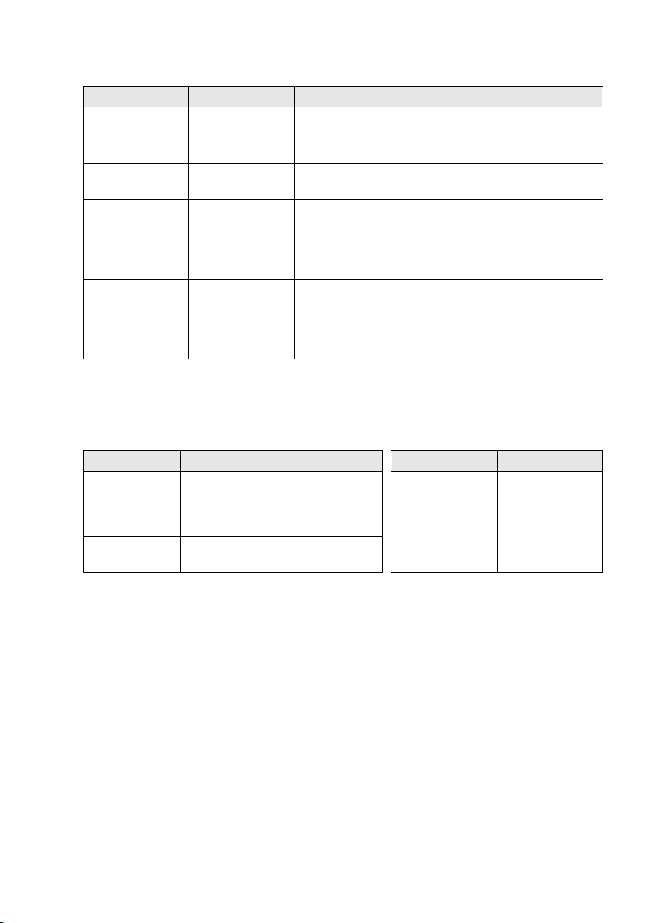
• SFP-SWRG-SX and SFP-SWRG-LX SPF modules
Standards supported: 1000BASE-SX/1000BASE-LX
This is necessary for connecting fiber optic cables.
Attach it to an SFP+ slot. For attachment instructions, refer to “Installing an SFP module”
(page 30) in “Connections”.
• SFP-SWRT-SR and SFP-SWRT-LR SFP modules
Standards supported: 10GBASE-SR/10GBASE-LR
This is necessary for connecting fiber optic cables.
Attach it to an SFP+ slot. For attachment instructions, refer to “Installing an SFP module”
(page 30) in “Connections”.
• DAC-SWRT-3M and DAC-SWRT-1M direct attachment cables
These are required for stack connections.
Attach it to an SFP+ slot. For attachment instructions, refer to “Installing a direct attachment
cable” (page 31) in “Connections”.
For information about Yamaha items sold separately, refer to the information page for this
product on the Yamaha website.
Separately sold items
Controls and connectors
6 SWX2310P-28GT Getting Started Guide
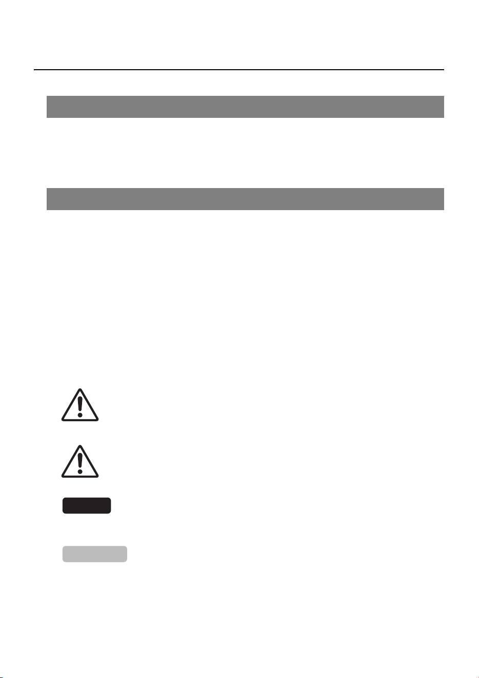
Controls and connectors
1 Power indicator
Lit when power is being supplied.
CAUTION
When one of the following errors is detected, the POWER indicator is lit orange. Check
and resolve the detected error as appropriate.
• Fan is stopped
The fan that blows hot air out of the product has stopped.
Stop using the product immediately and contact the dealer where it was purchased
to have it inspected and/or repaired.
• Internal temperature is abnormal
An internal temperature error has occurred inside the product.
Reassess the installation environment and install the product properly to achieve an
appropriate internal temperature.
Temperature and fan errors can be checked using the “show environment” command.
For details about the commands, refer to the “Command reference” on the information
page for this product on the Yamaha website.
2 mini-USB CONSOLE port
This mini-USB port is used to specify settings. Connect it to a computer USB port using a
USB cable equipped with a Type A connector and a USB mini Type B (5-pin). connector.
NOTE
Use a cable that supports data communication. Dedicated charging cables cannot be used.
Front panel
Power indicator Status
Unlit Power is OFF
Flashing (green) Power is ON and unit is starting up
Lit (green) Power is ON and supply is normal
Lit (orange) Power is ON, but an error occurred
1234560 7 9
8
0
0

Controls and connectors
SWX2310P-28GT Getting Started Guide
7
3
RJ-45 CONSOLE port
This RJ-45 port is used to specify settings. Use an RJ-45/DB-9 console cable to connect it
to a computer RS-232C connector (COM port).
4 microSD indicator
Indicates the microSD card connection and usage status.
NOTICE
Do not remove the microSD card if this indicator is flashing green.
5 microSD slot
Slot used to insert a microSD card.
6 LED MODE button and LED MODE indicator
Pressing the MODE button changes the port indicator display status in the following
sequence, which can be used to check the current upper and lower MODE indicator sta-
tus.
• If the initial indicator status is LINK/ACT, then pressing the button changes the status in
the following sequence:
[LINK/ACT] P [PoE] P [VLAN] P [STATUS] P [OFF] P [LINK/ACT]
• For more details about the MODE button and MODE indicators, refer to “Switching
between display modes” (page 11).
• For more details about the port indicator status for each MODE, refer to “Port indicators”
(page 12).
7 LAN ports
These 10BASE-T, 100BASE-TX, and 1000BASE-T Ethernet ports support supplying PoE
power in accordance with IEEE 802.3at.
The ports support IEEE802.3az energy efficient Ethernet (EEE) for achieving low-power
Ethernet communications (low power consumption mode).
For details on the low power consumption mode settings, refer to the “Command refer-
ence” (Yamaha website).
8 SFP+ slots
These 10GBASE-SR and 10GBASE-LR slots are used for connecting to separately sold
Yamaha SFP modules or direct attachment cables.
For instructions on installing SFP modules, refer to “Installing an SFP module” (page 30)
in “Connections”. For instructions on installing a direct attachment cable, refer to “Installing
a direct attachment cable” (page 31).
These ports can also be used for stack connections. For information about stack connec-
tions, refer to “Configuring stack connections” (page 32).
microSD indicator Status
Unlit A microSD card is not inserted in the slot.
Flashing green The microSD card is being accessed.
Lit green A microSD card is inserted.
Controls and connectors
8 SWX2310P-28GT Getting Started Guide
9 Stack ID indicator
This indicates the stack ID when a stack connection is used.
“1” is indicated when no stack connections are connected.
0 Cooling vents
These holes in the product are cooling vents for intaking external air.
WARNING
Do not block the cooling vents or place objects near them.
Doing so could cause a fire or product failure.
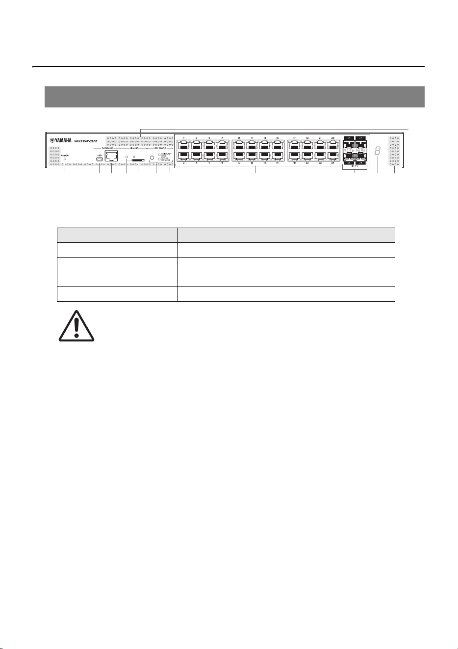
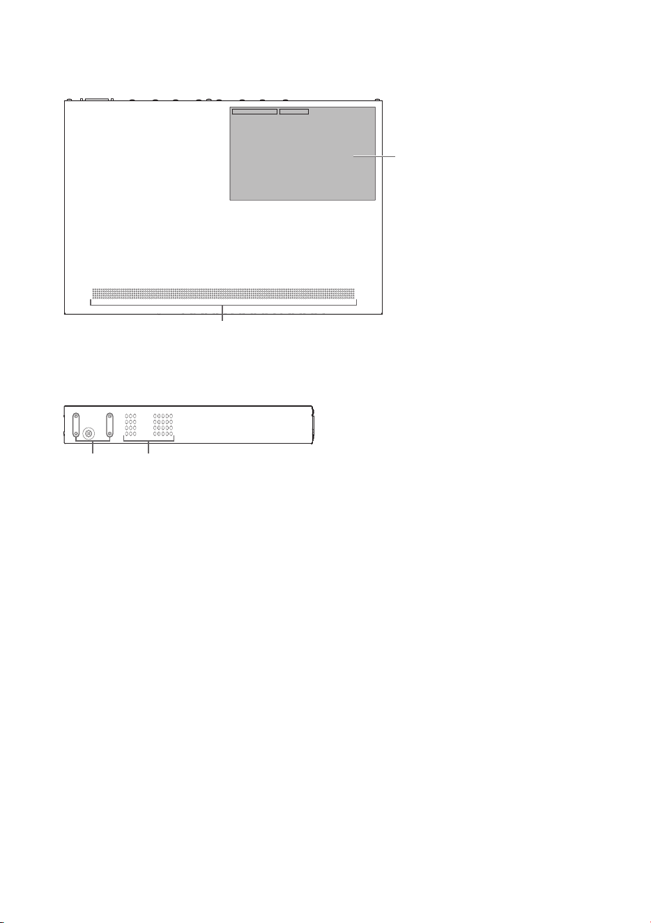
° Bottom panel
A Rubber foot attachment guides
These indicate where to attach the included rubber feet when installing the product hori-
zontally. For details on installation, refer to “Installing the product horizontally” (page 15) in
“Installation”.
Make sure the provided rubber feet are attached as shown if the product is to be installed
horizontally.
Bottom, rear, top, and side panels
A
A
Rubber feet
Controls and connectors
SWX2310P-28GT Getting Started Guide
9
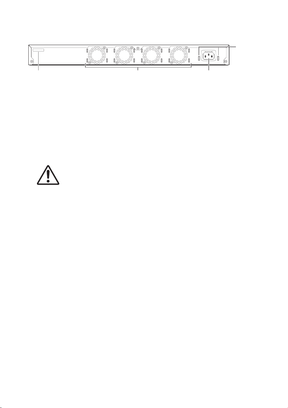
° Rear panel
B Power cord clamp attachment holes
Attach the included clamp (C-shaped) used to prevent power cord disconnection. For
installation instructions, refer to “Connecting the power cord” (page 33) in “Connections”.
C Serial number
The product label has the same indication.
D Fan
The fans are used to force out hot air generated inside the product.
If an error occurs, the POWER indicator is lit orange.
CAUTION
Do not block or place objects near the fan outlets.
Doing so could cause a fire or product failure.
E Power supply inlet (three-pin connector, C14 type)
Insert the included power supply cord here. Use a power cord that is appropriate for the
local power supply.
DEC
B
Controls and connectors
10 SWX2310P-28GT Getting Started Guide
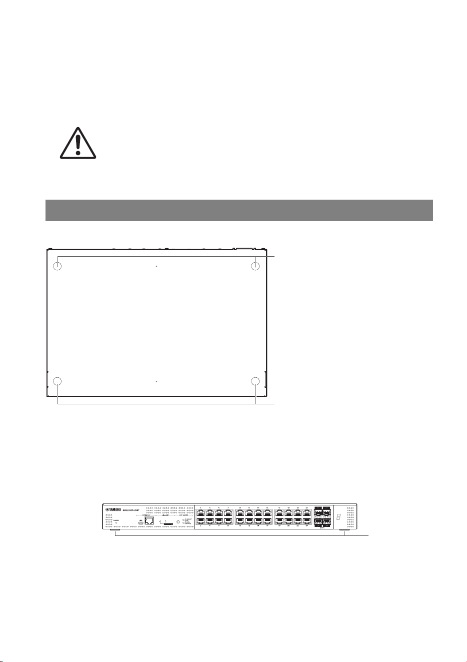
° Top panel
° Side panel
F Product label
This lists the model name, serial number, MAC address, and other product information.
G Rack mount accessory attachment holes
These are used when installing this product in a 19-inch rack (1U). For installation instruc-
tions, refer to “Installing the product in a 19-inch rack” (page 15) in “Installation”.
F
0
G0
Controls and connectors
SWX2310P-28GT Getting Started Guide
11
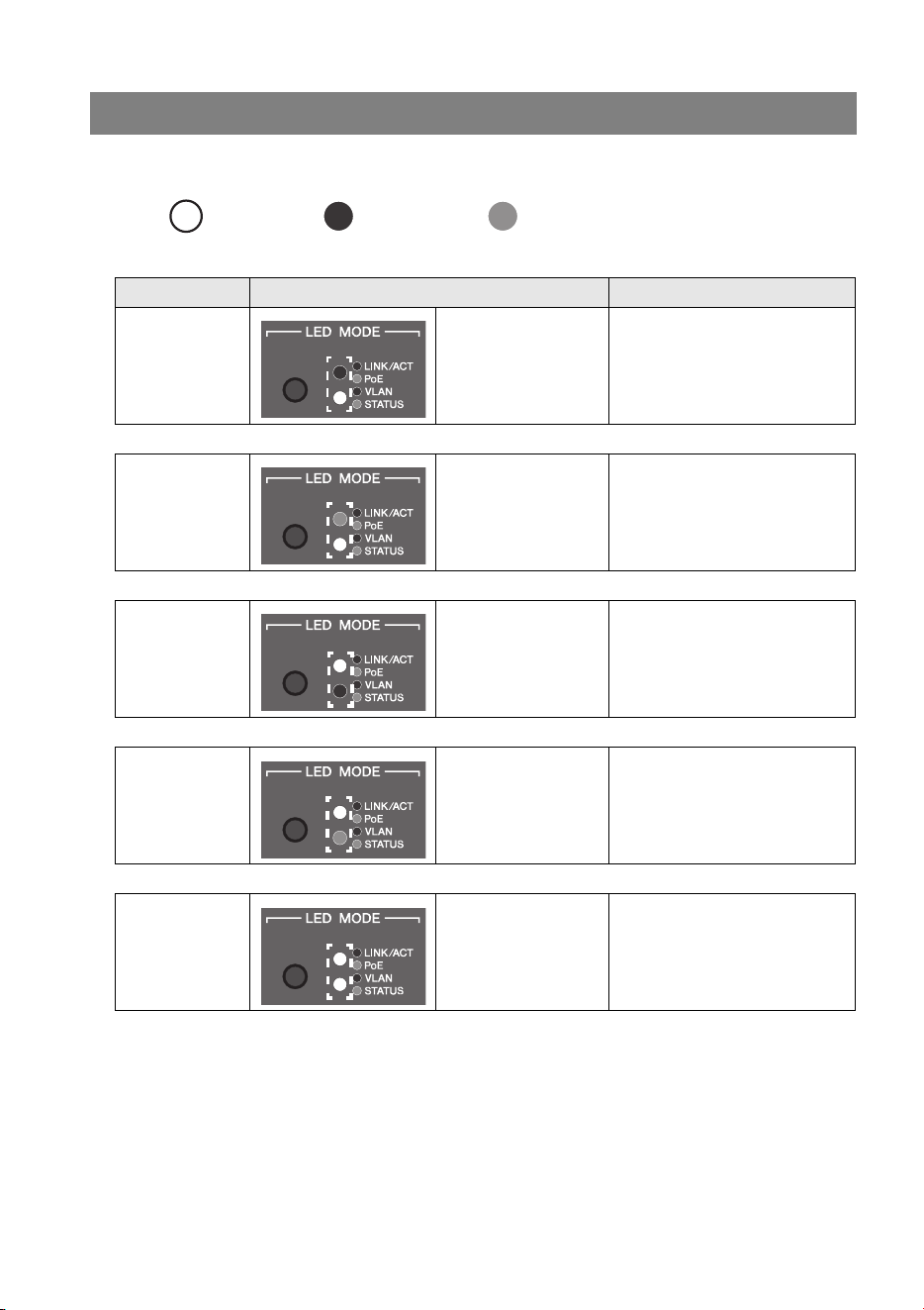
The port indicator display mode changes each time the MODE button is pressed. The
selected display mode is indicated by the lit upper and lower MODE indicators and their color.
Unlit: Lit (green): Lit (orange):
(assuming the initial display mode is LINK/ACT)
Switching between display modes
Mode name Status of lit MODE indicators Description
1 LINK/ACT
Upper: Lit (green)
Lower: Unlit
The left indicators for the LAN
ports and SFP+ slots indicate
the link status and the right
indicators indicate the
connection speed.
´
2 PoE
Upper: Lit (orange)
Lower: Unlit
Indicates the power supply
status at LAN ports.
´
3 VLAN
Upper: Unlit
Lower: Lit (green)
Indicates the VLAN ID
specified for LAN ports and
SFP+ slots.
´
4 STAT U S
Upper: Unlit
Lower: Lit (orange)
Indicates the error status of
LAN ports and SFP+ slots.
´
5 OFF
Upper: Unlit
Lower: Unlit
Switches OFF the indicators
for LAN ports, SFP+ slots, and
stack IDs.
´
1 Returns to LINK/ACT
Controls and connectors
12 SWX2310P-28GT Getting Started Guide
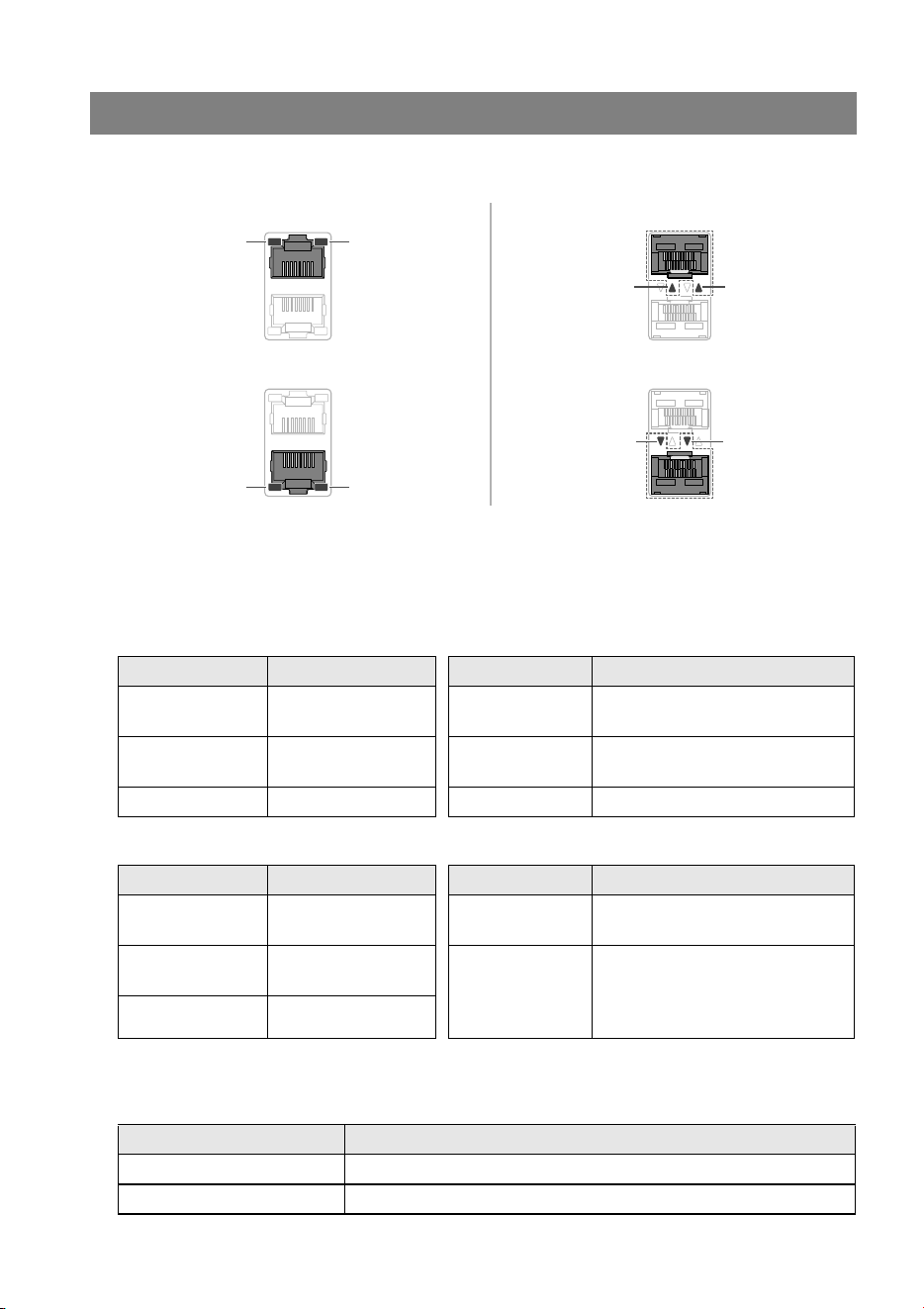
These LAN port and SFP+ slot indicators indicate the port status for each mode.
° LINK/ACT mode
This indicates the link status and connection speed of the LAN ports and SFP+ slots.
LAN ports
SFP+ slots
° PoE mode
Indicates the power supply status.
Port indicators
Left indicator Link status Right indicator Connection speed
Unlit
The link is broken
(unavailable).
Unlit
Not connected or connected via
10BASE-T cable.
Lit (green)
A link is established
(available).
Lit (orange) Connected via 100BASE-TX.
Flashing (green) Data is flowing. Lit (green) Connected via 1000BASE-T.
Left indicator Link status Right indicator Connection speed
Unlit
The link is broken
(unavailable).
Unlit Not connected
Lit (green)
A link is established
(available).
Lit (green)
Connected via an SFP module.
If using a direct attachment
cable, the connection speed is
10 Gbps.
Flashing (green) Data is flowing.
Left indicator Power supply status
Unlit Power is not being supplied.
Lit (green) Power is being supplied.
Left
indicator
LAN ports (upper)
LAN ports (lower) SFP+ slots (lower)
SFP+ slots (upper)
Left
indicator
Left
indicator
Left
indicator
Right
indicator
Right
indicator
Right
indicator
Right
indicator
Controls and connectors
SWX2310P-28GT Getting Started Guide
13
° VLAN mode
Indicates VLAN association status of LAN ports and SFP+ slots.
*1: The indicator lighting status for the seventh largest and larger VLAN ID values is the same.
NOTE
The default VLAN ID value (VID = 1) is not indicated as associated VLAN.
° STATUS mode
Indicates the error status of LAN ports and SFP+ slots.
When one of the following errors is detected, the mode is forcibly switched to the STATUS
mode and the left and right port indicators flash orange.
• Loop detected
• SFP light input level error detected
• PoE power supply interruption or powered-device error detected
Left indicator Right indicator VLAN ID
Indicator
assignment order
Unlit Unlit No ID –
Lit (green) Unlit Lowest VLAN ID value 1
Lit (orange) Unlit
Indicator lighting patterns
assigned in ascending order
of VLAN ID values.
2
Unlit Lit (green) 3
Unlit Lit (green) 4
Lit (green) Lit (orange) 5
Lit (orange) Lit (green) 6
Lit (green)
*1
7th largest and larger VLAN
ID values
7
Lit (orange) Lit (orange)
Associated to multiple
VLANs
–
Controls and connectors
14 SWX2310P-28GT Getting Started Guide
LAN ports
*1: For information about the total power supply of this product, refer to the maximum power supply
output values indicated in “Hardware specifications” (page 34). For information about guard band
operation, refer to the “Technical Data” indicated on the information page for this product on the
Yamaha website.
SFP+ slots
Refer to the “Technical Data” on the information page for this product on the Yamaha web-
site.
NOTE
• The cause of the error can be checked using the “show error port-led” command.
• The error status can be forcibly reset by holding down the MODE button (for 3 seconds).
• If all errors have been resolved or the error status was forcibly reset by holding down the MODE
button, the mode automatically switches to the initial display mode.
° OFF mode
Switches OFF the indicators for LAN ports, SFP+ slots, and stack IDs.
Left indicator Right indicator Error information
Unlit Unlit Normal
Flashing
(orange)
Unlit
A loop was detected.
The port was blocked or shut down.
Lit (orange) Unlit
Power is not being supplied due to a powered-device
error.
Unlit
Flashing
(orange)
The port power supply was stopped because the
product’s total power supply limit was exceeded.
The number of powered devices cannot be increased
because the total power supply exceeded the guard
band.
*1
Unlit Lit (orange)
The power supply stopped because the power output at
the port exceeded the maximum power supply limit per
port. The maximum power supply per port differs
depending on the power consumption class of connected
powered devices.
Left indicator Status Right indicator Status
Unlit
Normal
No loops were detected. The SFP
light input level is within the normal
range.
Unlit
(unlit regardless
of status)
Lit (green)
A loop or SFP light input level error
was detected.
Installation
SWX2310P-28GT Getting Started Guide
15
Installation
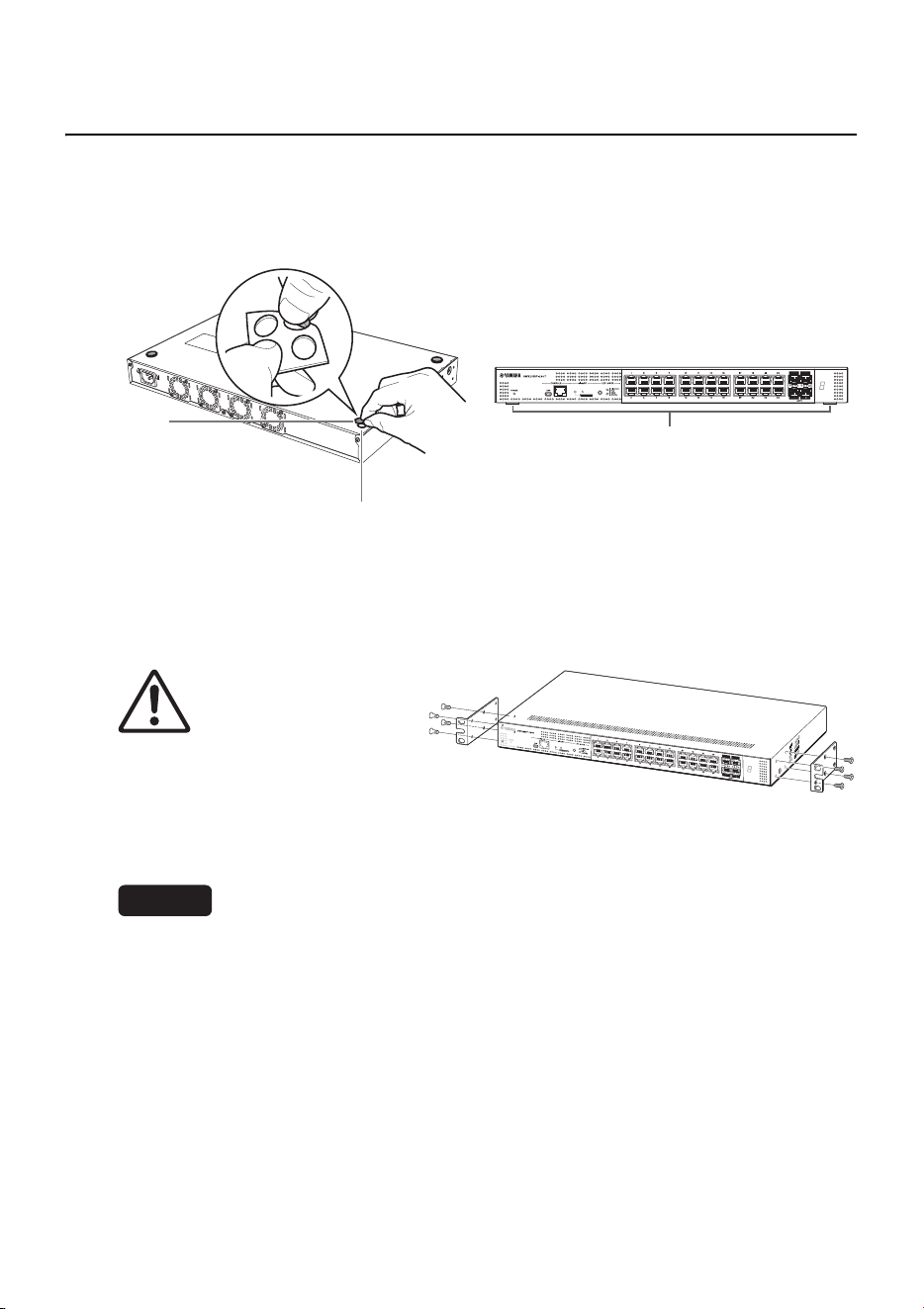
° Installing the product horizontally
Attach the included rubber feet in the positions indicated by the rubber foot attachment
guide. Then place the product in a horizontal location, such as on a desk.
° Installing the product in a 19-inch rack
This product conforms to the 1U size for mounting in a 19-inch rack. If installing the prod-
uct in a 19-inch rack, use the included screws (eight) to fasten the mounting brackets
(two).
WARNING
Make sure to use the included 19-
inch rack mount hardware and
screws.
Not doing so could cause an injury or
equipment damage from the unit falling.
It could also cause electric shock or a
malfunction.
NOTICE
• If the rack includes a door, make sure the door will not hit any communication cables or the
power cord after installation.
• Install it in the 19-inch rack with clearance provided to prevent blocking the vent holes on the top
panel or the fan air outlet holes on the back panel of the product.
NOTE
Screws for fastening this product to the 19-inch rack are not included.
Rubber
foot
Rubber feet
Rubber foot attachment guide
Use a Phillips screwdriver to securely
fasten the screws.
Installation
16 SWX2310P-28GT Getting Started Guide
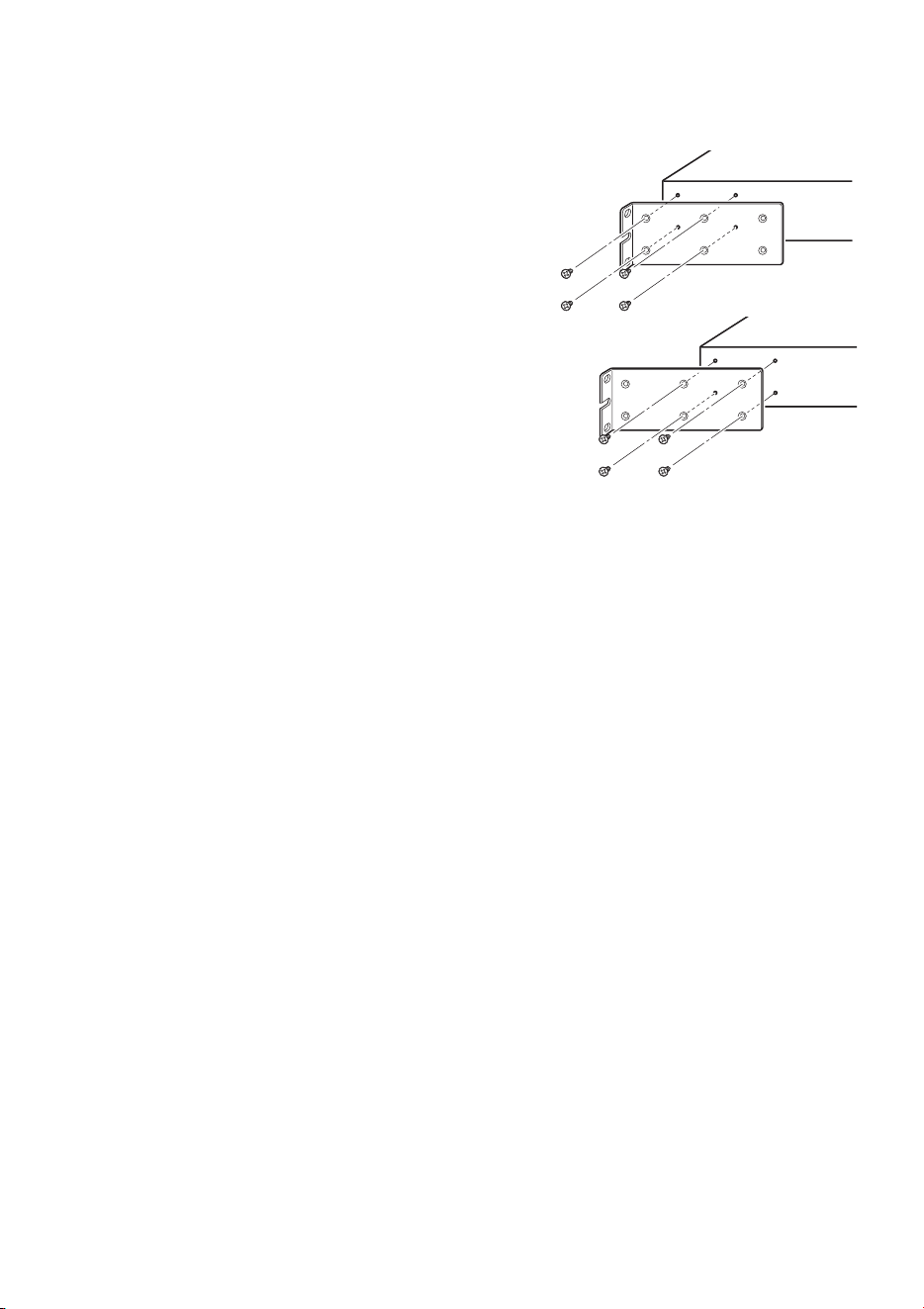
The 19-inch rack mounting brackets can be attached to the product using either of the fol-
lowing two methods.
Method A: Attach the 19-inch rack mounting
brackets so that the mounting flange is flush
with the front panel of the product.
This is the usual mounting method.
Method B: Install the product 4 cm deeper
into the rack than method A.
Use this mounting method if the 19-inch rack cabi-
net has a door. Doing so positions the product fur-
ther back so that the SFP module and LAN cables
connected to the front panel do not contact the rack
door.

Settings
SWX2310P-28GT Getting Started Guide
17
Settings
The settings for this product can be configured in the following ways.
• Using the CONSOLE port to specify settings from the command line (P.18)
• Using Telnet to specify settings from the command line (P.21)
• Using SSH to specify settings from the command line (P.23)
• Using the Web GUI to specify settings (P.25)
• Restoring product settings to default factory values (P.26)
Product settings can be accessed either by logging in as a general user or as an
administrator. This chapter explains how to log in as an administrator.
Refer to the “Technical Data” and “Command reference” on the information page for this
product on the Yamaha website.
Settings
18 SWX2310P-28GT Getting Started Guide
The following describes the cable, driver, software, and settings necessary for using the
CONSOLE port.
° Preparing the console cable
• Connect the computer to the product CONSOLE port using a USB cable or the RJ-45/
DB-9 console cable.
• Use a USB cable with a USB Type A connector and a mini-USB Type B (5-pin) connec-
tor, and that supports data communication, to connect to the mini-USB CONSOLE port.
Dedicated charging cables cannot be used.
° Installing the USB serial driver
• To use the mini-USB CONSOLE port, a USB serial driver must first be installed in the
computer.
• For USB serial driver installation instructions, refer to the “Yamaha Network Device USB
Serial Driver Installation Guide”.
The Yamaha Network Device USB Serial Driver Installation Guide and the installer can
be downloaded from the information page for this product on the Yamaha website.
° Preparing the computer
Terminal software for controlling the computer serial (COM) port is necessary. Configure
the terminal software parameter settings as follows.
If the computer is connected to both the RJ-45 CONSOLE port and the mini-USB CON-
SOLE port, then the settings can only be configured using the terminal software that uses
the mini-USB CONSOLE port.
Messages output from this product are output to both CONSOLE ports.
° Logging in from a computer connected to the CONSOLE port
1. Connect the product to the computer using a console cable.
Connect the computer to the p1roduct CONSOLE port using a USB cable or an RJ-45/
DB-9 console cable.
Using the CONSOLE port to specify settings from the
command line
Parameter Value
Data transmission speed 9600 bit/s
Character bit length 8
Parity check None
Number of stop bits 1
Flow control Xon/Xoff
Settings
SWX2310P-28GT Getting Started Guide
19
NOTICE
• The LAN and RJ-45 CONSOLE ports have the same 8-pin connector shape. An incor-
rect connection at those ports could cause hardware damage or product failure.
Take care when connecting the cable.
• If using the mini-USB CONSOLE port, do not use a USB hub.
If multiple Yamaha routers or switches are connected to one computer, COM port numbers
assigned for certain connections might be inadvertently interchanged in some cases.
Beware that it might result in unintended changes to device settings.
2. Check the product power supply.
If the product power supply is not turned on, turn on the power as described in “Con-
necting the power cord” (page 33). When this product power is turned on and the com-
mand line is available, a startup message appears on the console screen of the
computer.
If the power is already on, a startup message does not appear.
3. Press the [Enter] key.
The system will wait for a username to be entered.
4. Enter the username and press the [Enter] key.
If settings are still set to factory default values, enter the default administrator user-
name “admin”.
The system will wait for a password to be entered.
5. Enter the user password specified in step 4 and press the [Enter] key.
If factory settings are specified, enter the default administrator password “admin”.
NOTE
• Character strings entered in the password field are not displayed on the console screen.
(That also applies for the steps below.)
• If an incorrect password is entered three consecutive times, logging in to the product is
disabled for one minute. If that occurs, wait at least one minute before trying again,
starting from step 4.
Before changing the default password for the default administrator:
When the default password is successfully authenticated, the system will wait for a new
password to be entered.
Skip to step 6 and change the password.
SWX2310P-28GT Rev. 2.02.30 (Mon Feb 3 09:36:55 2025)
Copyright (c) 2022 Yamaha Corporation. All Rights
Reserved.
Username: admin
Password:
Settings
20 SWX2310P-28GT Getting Started Guide
After changing the default password for the default administrator:
After the password is successfully authenticated, the command prompt will appear to
enable entering commands. That completes the login process. (The remaining steps
are not necessary.)
6. Enter the new password and press the [Enter] key.
The system will wait for the new password to be re-entered.
7. Re-enter the same password as in step 6 and press the [Enter] key.
If the password was successfully changed, the command prompt will appear to enable
entering commands.
For details about the commands, refer to the “Command reference” on the information
page for this product on the Yamaha website.
SWX2310P-28GT Rev. 2.02.30 (Mon Feb 3 09:36:55 2025)
Copyright (c) 2022 Yamaha Corporation. All Rights
Reserved.
Please change the default password for “admin”.
New password:
SWX2310P>
New password:
New password (confirm):
Saving ...
Succeeded to write configuration
SWX2310P>

Settings
SWX2310P-28GT Getting Started Guide
21
The following describes how to log in to the product from a host on a LAN using a Telnet
client.
° Using a Telnet client to log in to the product
A computer or other Telnet client can be used to connect to the product Telnet server.
The following example describes how to connect to the product Telnet server using a Win-
dows Telnet client.
NOTE
If using a Windows operating system, Telnet functionality is disabled in default settings. To use Tel-
net functionality, the Telnet client must be enabled.
1. Connect the product to the computer using a LAN cable.
2. Check the product power supply.
If the product power supply is not turned on, turn on the power as described in “Con-
necting the power cord” (page 33). Once the power is on, go to step 3.
3. Launch the Windows command prompt.
4. Use the “telnet” command to enter the product IP address and then press
[Enter].
If product settings are still set to factory default values, enter “192.168.100.240” after
the “telnet” command.
The system will wait for a username to be entered.
5. Enter the username and press the [Enter] key.
If settings are still set to factory default values, enter the default administrator user-
name “admin”.
The system will wait for a password to be entered.
6. Enter the user password entered in step 5 and press the [Enter] key.
If settings are still set to factory default values, enter the default administrator password
“admin”.
Using Telnet to specify settings from the command
line
telnet 192.168.100.240
Username: admin
Password:
Settings
22 SWX2310P-28GT Getting Started Guide
NOTE
• Character strings entered in the password field are not displayed on the console screen.
(That also applies for the steps below.)
• If an incorrect password is entered three consecutive times, logging in to the product is
disabled for one minute. If that occurs, wait at least one minute before trying again,
starting from step 5.
Before changing the default password for the default administrator:
When the default password is successfully authenticated, the system will wait for a new
password to be entered.
Skip to step 7 and change the password.
After changing the default password for the default administrator:
After the password is successfully authenticated, the command prompt will appear to
enable entering commands. That completes the login process. (The remaining steps
are not necessary.)
7. Enter the new password and press the [Enter] key.
The system will wait for the new password to be re-entered.
8. Re-enter the same password as in step 7 and press the [Enter] key.
If the password was successfully changed, the command prompt will appear to enable
entering commands.
For details about the commands, refer to the “Command reference” on the information
page for this product on the Yamaha website.
SWX2310P-28GT Rev. 2.02.30 (Mon Feb 3 09:36:55 2025)
Copyright (c) 2022 Yamaha Corporation. All Rights
Reserved.
Please change the default password for “admin”.
New password:
SWX2310P>
New password:
New password (confirm):
Saving ...
Succeeded to write configuration
SWX2310P>

Settings
SWX2310P-28GT Getting Started Guide
23
The following describes the preparations for using an SSH client to log in to the product from
a host on a LAN.
For login instructions, refer to the SSH client owner’s manual.
NOTICE
Beware that the following functionality is not supported by the product’s SSH server functionality.
• SSH protocol ver. 1
• User authentication methods other than password authentication
(host base authentication, public key authentication, challenge-response authentication, or
GSSAPI authentication)
• Port forwarding (X11/TCP forwarding)
• Gateway ports (port relaying)
• Allowing empty passwords
° Settings for enabling SSH server functionality
Product SSH server functionality is disabled in default factory settings.
To log in to the product using an SSH client, a separate method must be used to first log in
to the product and change the following settings.
• Enable the product’s SSH server functionality.
• Register the user(s) that may access the SSH server.
NOTE
The following assumes the user has successfully logged in as described in “Using the CONSOLE
port to specify settings from the command line” (page 18).
1. Enter “enable” and press the [Enter] key.
Change to the privileged EXEC mode.
2. Use the “ssh-server host key generate” command to generate a host key for the
SSH server.
NOTE
The “ssh-server host key generate” command generates a DSA or RSA public key and a
private key as a pair of keys. Note that it may take several tens of seconds to process the
command, depending on the model.
Using SSH to specify settings from the command line
SWX2310P>enable
SWX2310P#
SWX2310P#ssh-server host key generate
SWX2310P#
Settings
24 SWX2310P-28GT Getting Started Guide
3. Enter “configure terminal” and press the [Enter] key.
Change the command input mode to the global configuration mode.
4. Use the “ssh-server enable” command to enable SSH server functionality.
5. Register a user with a password using the “username” command.
IMPORTANT
The SSH server requires a username and password to log in. Be sure to register a user with
password ahead of time.
Example: Username: yamaha; Password: 1a2b3c4d
6. Enter “exit” and press the [Enter] key.
The mode is changed back to privileged EXEC mode.
7. Save the settings as necessary.
For details about the commands, refer to the “Command reference” on the information
page for this product on the Yamaha website.
Refer to the owner’s manual of the SSH client you are using for the SSH client settings
and operations.
SWX2310P#configure terminal
Enter configuration commands, one per line. End with
CNTL/Z.
SWX2310P(config)#
SWX2310P(config)#ssh-server enable
SWX2310P(config)#
SWX2310P(config)#username yamaha password 1a2b3c4d
SWX2310P(config)#
SWX2310P(config)#exit
SWX2310P#
SWX2310P#write
Building configuration...
[OK]
SWX2310P#

Settings
SWX2310P-28GT Getting Started Guide
25
The following describes how to log in to the product using the Web GUI.
° Logging in to the product using a web browser
1. Open the Web browser and access “http://<product IP address>/”.
When access is successful, a login screen appears for entering a username and pass-
word.
NOTE
• The factory default IP address of this product is “192.168.100.240/24”.
• If the product is not connected to a network, change the IP address of the computer used to
configure settings to the “192.168.100.0/24” segment.
For instructions on how to change the computer IP address setting, refer to the computer
owner’s manual.
2. Enter the username and password. Then click the “Login” button.
If settings are set to factory settings, enter “admin” as the default administrator and
“admin” as the password.
If settings are set to factory settings, a language selection screen is displayed after suc-
cessfully logging in.
NOTE
If an incorrect username or password is entered three consecutive times, product logging
is disabled for one minute. If that occurs, wait at least one minute before trying again,
starting over from step 2.
3. Select the language to use.
If settings are set to factory settings, a screen for changing the password is displayed
after login.
NOTE
The user language can also be changed via the Web GUI after login.
4. Enter the new password in both fields and then click “Save”.
If the password was successfully changed, the top screen of the Web GUI is displayed.
Using the Web GUI to specify settings

Settings
26 SWX2310P-28GT Getting Started Guide
The following describes how to restore product settings to default factory values.
• Using the “cold start” command to restore factory settings (P.26)
• Restoring factory settings by rebooting the product while holding down the uppercase [I] key
(P.27)
• Restoring factory settings from the product Web GUI (P.28)
NOTICE
When restoring the factory settings, note the following points.
• All communication is halted immediately after execution.
• The IP address of the product will be reset to the factory default setting (192.168.100.240).
• Once settings are reset to default factory values, they cannot be restored to previous values. If
necessary, save the settings in external memory before they are reset. For more details about
how to export settings to external memory, refer to the “Technical Data” indicated on the infor-
mation page for this product on the Yamaha website.
NOTE
For instructions on logging in after restoring factory settings, see “Settings” (page 17).
° Using the “cold start” command to restore factory settings
The CONSOLE port, Telnet, or an SSH client can be used to restore factory settings from
a command line.
NOTICE
If logged in via Telnet or an SSH client, then corresponding communications will be halted.
IMPORTANT
This step cannot be executed if the administrator password is set to the default value. Use the
“enable password” command to change the administrator password in advance.
NOTE
The following assumes the user is successfully logged in as described in “Logging in from a com-
puter connected to the CONSOLE port” (page 18) or “Using Telnet to specify settings from the
command line” (page 21).
1. Enter “enable” and press the [Enter] key.
The mode is changed to the privileged EXEC mode.
Restoring product settings to default factory values
SWX2310P>enable
SWX2310P#

Settings
SWX2310P-28GT Getting Started Guide
27
2. Enter the “cold start” command and press the [Enter] key.
You will be prompted to enter the administrator password.
3. Enter the administrator password and press [Enter] key.
The settings saved in the product are reset to their factory default values, SYSLOG is
deleted, and then the product is rebooted.
° Restoring factory settings by rebooting the product while holding down the
uppercase [I] key
Settings can be restored to factory values by holding down the uppercase [I] key while
rebooting the product. The following describes how to restore factory settings using the
“reload” command to reboot the product. The procedure is also the same for rebooting the
product by disconnecting and reconnecting the power cord.
NOTE
The following assumes the user has successfully logged in as described in “Logging in from a
computer connected to the CONSOLE port” (page 18).
1. Enter “enable” and press the [Enter] key.
The mode is changed to the privileged EXEC mode.
2. Enter the “reload” command and press the [y] key.
The product will reboot.
3. After rebooting, enter an uppercase “I” within one second after the “BootROM
Ver” (see below) appears on the console screen.
NOTE
Pressing the [Caps Lock] key or holding down the [Shift] key in advance, before the “Boot-
ROM Ver” appears on the console screen, allows the uppercase [I] key to be pressed right
away.
SWX2310P#cold start
Password:
SWX2310P>enable
SWX2310P#
SWX2310P#reload
reboot system? (y/n): y
SWX2310P BootROM Ver.1.00

Settings
28 SWX2310P-28GT Getting Started Guide
4. When an initialization confirmation screen appears to confirm whether or not to
execute initialization, press the [y] key to execute initialization.
Initialization is executed.
° Restoring factory settings from the product Web GUI
This unit can be restored to its factory-set state by making settings from the Web GUI.
IMPORTANT
This step cannot be executed if the administrator password is set to the default value. Change the
administrator password in advance.
The following assumes the user has successfully logged in as described in “Logging in to
the product using a web browser” (page 25).
1. Click the “Management” tab, “Maintenance”, and “Restart and initialization”, in
that order.
The “Restart and initialization” screen appears.
2. In the “Initialization” section, click the “Next” button.
The “Initialization” screen appears.
3. Enter the administrator password and click “Confirm”.
The “Check executed content” screen appears.
4. Verify the content, and click the “OK” button.
The product is restored to factory settings. In addition, the “Initialization” dialog box
appears and the product is rebooted.
5. When the product is finished rebooting, open the Web GUI again.
NOTE
During the reboot, computer communication with the product is disabled while the Web
GUI is open. (The computer status indicated in the network adapter is “Network cable is
not connected”.) Communication will be restored when the reboot is completed. After
rebooting, the IP address of the product will be 192.168.100.240. To display the web GUI
again, access “192.168.100.240”.
Initialize or not ?(y/n)
Ready to Initialize
...............
Connections
SWX2310P-28GT Getting Started Guide
29
Connections
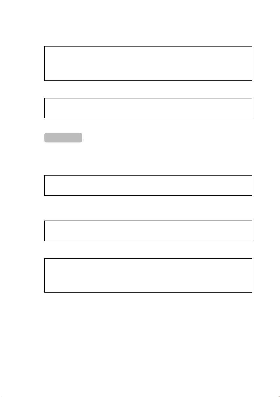
° Connecting to a network device or computer
Use LAN cables to connect a
LAN port on the network
device or computer to a prod-
uct LAN port.
If connecting the network
device or computer via a fiber
optic cable, install an appropri-
ate SFP module in the SFP+
slot. For installation instructions, refer to “Installing an SFP module” (page 30).
NOTICE
The LAN and RJ-45 CONSOLE ports have the same 8-pin connector shape. An incorrect connec-
tion at those ports could cause hardware damage or product failure. Take care when connecting
the cable.
NOTE
When the initial display mode is set to “LINK/ACT” mode, you will be able to check the connection
status between the network equipment and your computer. For more details about switching
between modes or the connection status, refer to “Switching between display modes” (page 11)
and “Port indicators” (page 12).
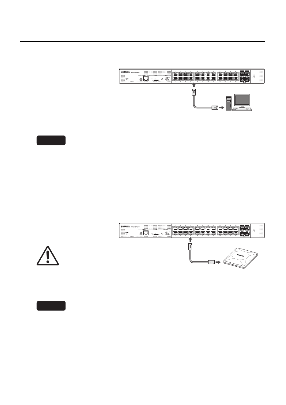
° Connecting to a PoE-powered device
Use a LAN cable to connect
the product to a PoE-powered
device.
WARNING
Use a CAT 5e or better cable to
connect IEEE802.3at-compliant
powered devices.
Connecting a cable that is not
IEEE802.3at-compliant could cause a fire or product failure.
NOTICE
The LAN and RJ-45 CONSOLE ports have the same 8-pin connector shape.
An incorrect connection at those ports could cause hardware damage or product failure. Take care
when connecting the cable.
NOTE
The power supply status of PoE-powered devices can be checked by using the MODE button to
switch to the “PoE” mode. For more details about switching modes or the power supply status,
refer to “Switching between display modes” (page 11) and “Port indicators” (page 12).
Computer
WLX402
(PoE-powered device)
Connections
30 SWX2310P-28GT Getting Started Guide
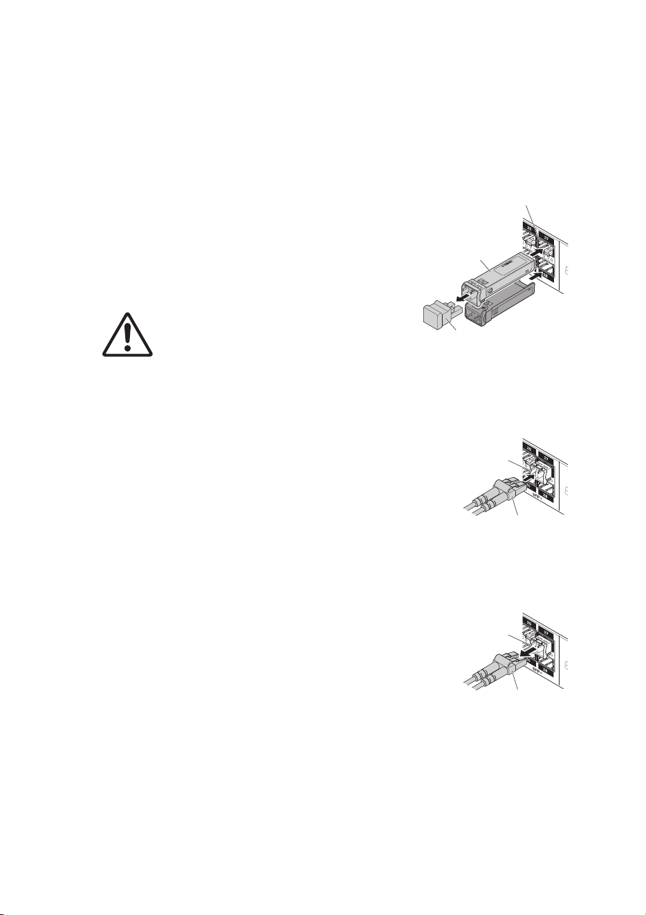
° Installing an SFP module
SFP modules can be installed in an SFP+ slot of the product.
NOTE
For more details about how to install or remove SFP modules and corresponding precautions,
refer to the “Owner’s Manual” included with the module.
1. Remove the dust cover from the product
SFP+ slot and insert the SFP module.
NOTE
Since this product supports hot-swapping, SFP mod-
ules can be installed without turning off the power.
2. Remove the protective cap from the SFP
module.
CAUTION
Do not look into the optical emitter after installing
an SFP module.
SFP modules sold separately by Yamaha are class 1 laser devices. They can emit laser light
invisible to the eye. If laser light enters an eye, it could damage eyesight.
3. To the connector, connect a fiber optic cable that is
suitable for each module.
° Removing an SFP module
While securing the product to prevent it from moving, grasp
the lever on the SFP module and slowly pull it toward the
front to remove the module from the SFP+ slot.
NOTE
For more details about how to install or remove SFP modules and corresponding precautions,
refer to the “Owner’s Manual” included with the module.
1. Detach the fiber optic cable.
L
a
se
r Cl
a
ss
1
S/N
:
Protective cap
SFP+ slot
SFP module
Connector
Fiber optic cable
Connector
Fiber optic cable
Connections
SWX2310P-28GT Getting Started Guide
31
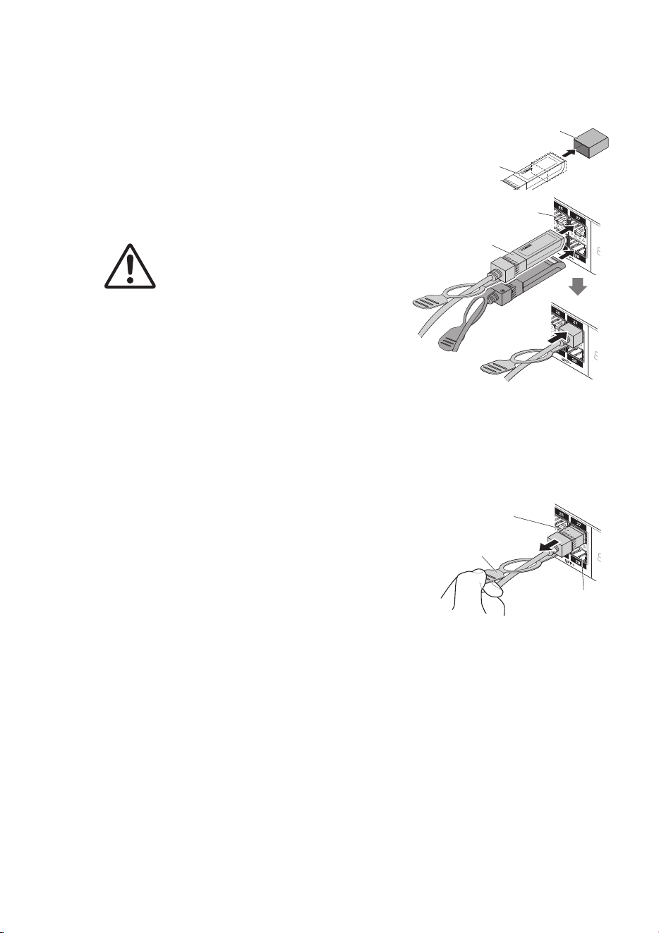
° Installing a direct attachment cable
The product SFP+ slots enable the attachment of direct attachment cables.
1. Remove the dust cover from the SFP+ slot
and remove the protective cap from the
direct attachment cable.
2. Grasp the body of the direct attachment
cable and insert it securely into the prod-
uct SFP+ slot.
CAUTION
If configuring a stack connection using a direct
attachment cable, make sure the connected
devices are mutually grounded to an equipoten-
tial ground.
Connecting two devices that have different ground-
ing potentials with a direct attachment cable could
cause a malfunction or device failure.
NOTE
Since this product supports hot-swapping, direct attachment cables can be installed with-
out turning off the power.
° Removing a direct attachment cable
While securing the SWX2310P-28GT unit to pre-
vent it from moving, grasp the removal pull tab on
the direct attachment cable and slowly pull it toward
the front to remove the direct attachment cable from
the SFP+ slot.
NOTE
Since this product supports hot-swapping, a direct attach-
ment cable can be removed without turning the power off.
Protective cap
Direct attachment
cable body
SFP+ slot
Direct attachment
cable body
SFP+ slot
Removal pull tab
Direct attachment
cable body

Connections
32 SWX2310P-28GT Getting Started Guide
° Configuring stack connections
IMPORTANT
To use stack functions, firmware that supports stack functions is required. For more information,
refer to the “Technical Data” on the information page for this product on the Yamaha website.
Install a direct attachment cable or SFP module in an SWX2310P-28GT SFP+ slot. If
using an SFP module, also separately provide a fiber optic cable suitable for SFP+ mod-
ules.
For direct attachment cable attachment/detachment instructions, refer to “Installing a direct
attachment cable” (page 31) and “Removing a direct attachment cable” (page 31).
For SFP module installation instructions, refer to “Installing an SFP module” (page 30).
NOTE
For more details, such as how to install or remove SFP modules and corresponding precautions,
refer to the “Owner’s Manual” included with the direct attachment cable.
For more details about stack connections, refer to the “Technical Data” on the information
page for this product on the Yamaha website.
Connections
SWX2310P-28GT Getting Started Guide
33
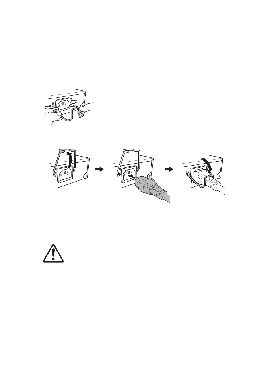
° Connecting the power cord
1. Attach the included power cord clamp.
• To prevent accidental power cord disconnection, secure the cord with the included power cord
clamp (indicated as “included clamp” in the figure below) inserted into the power cord clamp
holes of the product (indicated as “holes in the product” in the figure below).
• The included power cord clamp is designed specifically for the included power supply cord.
• Using the clamp for other power cords that are not included could cause cord damage or pre-
vent securing the cord adequately.
2. Connect the included power cord to the power supply inlet and secure it with the
clamp.
3. Connect the power cord to a power supply outlet.
The POWER indicator will flash green and remain lit after startup.
CAUTION
If the POWER indicator is lit orange, it indicates that the fans have stopped or an abnormal
temperature occurred inside the product. Check and resolve the error situation appropriately.
• Fan is stopped
Stop using the product immediately and contact the dealer where it was purchased to have
it inspected and/or repaired.
• Internal temperature is abnormal
Reassess the installation environment and install the product properly to achieve an appro-
priate internal temperature.
4. Check the port indicator.
Use the MODE button to switch display modes and check the port indicator status.
For more details about switching display modes or the power supply status, refer to
“Switching between display modes” (page 11) and “Port indicators” (page 12).
Insert the included clamp into
the holes in the product.
1 Raise the clamp. 2 Connect the power
cord.
3 Press down on the
clamp to secure the
power cord.
Appendix
34 SWX2310P-28GT Getting Started Guide
Appendix
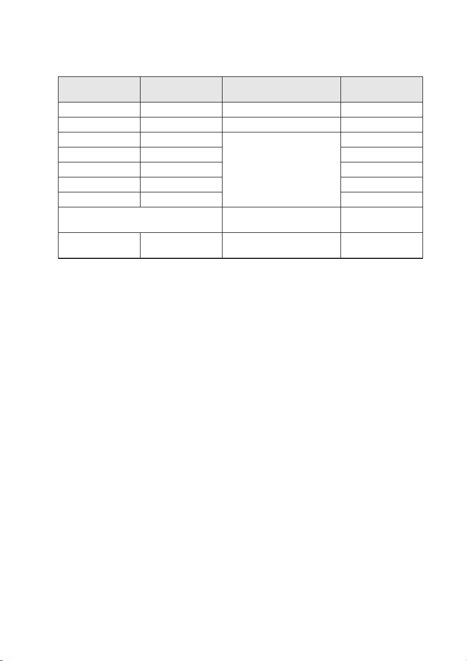
Hardware specifications
Item SWX2310P-28GT
External dimensions (mm)
W x D x H, not including
protrusions and feet
440 x 294 x 44
Weight (excluding included
items)
3.9 kg
Power supply voltage and
frequency
100 – 240 V AC, 50/60 Hz
Maximum power consumption 459 W
CONSOLE
port
Standard RS-232C, USB 2.0
Connector RJ-45, USB mini-B (5-pin)
Data
transmission
speed
9600 bit/s
LAN ports
Standard
IEEE802.3 (10BASE-T/100BASE-TX/1000BASE-T)
Combo ports only support 1000BASE-T
Number of
ports
24
Communication
mode
Auto-negotiation
Connector RJ-45
Polarity Automatic straight/cross detection or fixed straight
Ports with PoE power supply
24 ports
(ports 1 to 24)
PoE standard IEEE 802.3at
Power supply method Alternative A
Max. power
supply
capacity
Per port
30 W (differs depending on the power consumption class of
connected powered devices)
Total for all
ports
370 W
Supported PoE-powered
devices
PoE-powered devices that conform to the IEEE 802.3af or IEEE
802.3at standard
SFP+ slot
Standard
IEEE802.3z (1000BASE-SX/1000BASE-LX) or IEEE802.3ae
(10GBASE-SR/10GBASE-LR)
Number of slots 4
Appendix
SWX2310P-28GT Getting Started Guide
35
microSD slot
Standard microSD/microSDHC (microSDXC is not supported)
File System FAT/FAT32
Indicators
POWER, microSD,
MODE, STACK ID display, and LAN ports
SFP+ slots
Button MODE (for switching between display modes)
Fans Number of fans 4
MAC address Indicated on bottom panel product label
Radio frequency interference
standard
VCCI Class A
Operating
environment
conditions
Ambient
temperature
0 – 50 °C
Ambient
humidity
15 – 80% (non-condensing)
Storage
environment
conditions
Ambient
temperature
−20 – +50 °C
Ambient
humidity
10 – 90% (non-condensing)
Item SWX2310P-28GT

© 2017 Yamaha Corporation
Published 02/2025
IP-C0