PANAVISION.COM

Table of Contents 2
Compliance Statements 4
Safety Instructions 6
Product Introduction 7
R3D File Format and REDCODE 7
Post Production 7
Camera System Components 8
Camera Body 8
Media 13
DXL Hot Swap Module 14
FIZ Module 21
Lens Mount 21
Additional Components 21
Basic Operations 22
Power Operations 22
Set Up the DXL Hot Swap Module 25
Record 27
Basic Menus and User Interface 28
GUI Menu Introduction 28
Home Page 29
User Page 31
Monitor Page 33
Audio Page 34
Menus Only Accessible Via Home and User
Pages 35
Detailed Menus 42
Project Settings 42
Monitoring 57
Media Menu 65
Look Menu 67
User Presets Menu 73
Network Menu 80
Maintenance 86
Playback 104
Audio System 106
Audio Overview 106
Control 107
Monitor Mix 110
Audio Output 112
Audio Meter (VU Meter) 112
COP YRIGHT © 2020 PAN AVISION INTERN A TION AL, L.P . FW : V-1.0.0| 2
PANAVISION MILLENNIUM DXL2
TABLE OF CONTENTS
Audio During Playback 113
Timecode, Genlock, Multi-Camera Setup 114
Timecode 114
Genlock 116
Master/Slave Operation 118
Set Up Stereo/3D Configuration 122
Camera Array 123
Compatible Timecode Devices 123
Compatible Genlock Devices 124
Upgrade Camera Firmware 125
Verify Current Camera Firmware 125
Upgrade Camera Firmware 125
Camera System Maintenance 126
Camera Body and Accessory Exterior Surfaces 126
Water Damage 126
Troubleshoot Your Camera 127
General Troubleshooting 127
Error Messages 131
APPENDIX A: Technical Specifications 132
Panavision Millennium DXL2 132
APPENDIX B: Mechanical Drawings 133
Front View 133
Back View 134
Side View (Right) 135
Side View (Left) 136
Top View 137
APPENDIX C: Input/Output Connectors 138
USB Power 141
DC-IN 141
6G/3G HD-SDI 142
3G HD-SDI 143
RETURN 143
14V Aux Power Out 144
AUX Power Out 145
TIMECODE 146
GENLOCK 146
GIG-E 147
LCD/EVF Ports 147
14V Aux Power Out 147
24V Aux Power Out 148

COMPLIANCE STATEMENTS
INDUSTRIAL CANADA EMISSION COMPLIANCE STATEMENTS
This device complies with Industry Canada license-exempt RSS standards
RSS 139 and RSS 210. Operation is subject to the following two conditions:
(1) this device may not cause interference, and (2) this device must accept
any interference, including interference that may cause undesired
operation of the device.
This Class B digital apparatus complies with Canadian ICES-003.
Le présent appareil est conforme aux CNR d’Industrie Canada applicables
aux appareils radio exempts de licence. L’exploitation est autorisée aux deux
conditions suivantes : (1) l’appareil ne doit pas produire de brouillage, et (2)
l’utilisateur de l’appareil doit accepter tout brouillage radioélectrique subi,
même si le brouillage est susceptible d’en compromettre le
fonctionnement.Cet appareil numérique de la classe B est conforme à la
norme NMB-003 du Canada.
FEDERAL COMMUNICATIONS COMMISSION (FCC) STATEMENTS
This equipment has been tested and found to
comply with the limits for a Class B digital device,
pursuant to part 15 of the FCC Rules. These limits
are designed to provide reasonable protection
against harmful interference in a residential
installation. This equipment generates, uses and
can radiate radio frequency energy and, if not
installed and used in accordance with the instructions, may cause harmful
interference to radio communications. However, there is no guarantee that
interference will not occur in a particular installation. If this equipment does
cause harmful interference to radio or television reception, which can be
determined by turning the equipment off and on, the user is encouraged
to try to correct the interference by one or more of the following
measures:
Reorient or relocate the receiving antenna.
Increase the separation between the equipment and receiver.
Connect the equipment into an outlet on a circuit different from that
to which the receiver is connected.
Consult the dealer or an experienced radio/TV technician for help.
In order to maintain compliance with FCC regulations, shielded cables must
be used with this equipment. Operation with non-approved equipment or
unshielded cables is likely to result in interference to radio and TV
reception. The user is cautioned that changes and modifications made to
the equipment without the approval of manufacturer could void the users
authority to operate this equipment.
NOTE: This device complies with Part 15 of the FCC Rules.
Operations subjected to the following two conditions (1) this device may
not cause harmful interference, and (2) this device must accept any
interference received, including that may cause undesirable interference.
CAUTION: Exposure to Radio Frequency Radiation.
The device shall be used in such a manner that the potential for human
contact is minimized.
COP YRIGHT © 2020 PA N A VISION IN TERN ATION AL, L.P . FW : V-1.0.0| 4
PANAVISION MILLENNIUM DXL2
This equipment complies with FCC radiation exposure limits set forth for an
uncontrolled environment. This equipment should be installed and
operated with a minimum distance of 20 cm between the radiator and
your body.
CAUTION: Regulations of the FCC and FAA prohibit
airborne operation of radio- frequency wireless
devices because there signals could interfere with
critical aircraft instruments.
CAUTION: If the device is changed or modified
without permission, the user may void his or her
authority to operate the equipment.
AUSTRALIA AND NEW ZEALAND STATEMENTS
Panavision declares that the radio equipment described in this document
comply with the following international standards.
IEC 60065 – Product Safety
ETSI EN 300 328 – Technical requirement for radio equipment
Panavision declares digital devices described in this document comply with
the following Australian and New Zealand standards.
AS/NZS CISPR 22 – Electromagnetic Interference
AS/NZS 61000.3.2 – Power Line Harmonics
AS/NZS 61000.3.3 – Power Line Flicker
JAPAN STATEMENTS
This is a Class B product based on the
standard of the Voluntary Control Council for
Interference (VCCI) for information technology
equipment. If this equipment is used near a
radio or television receiver in a domestic
environment, it may cause radio interference.
Install and use the equipment according to the
instruction manual.
EUROPEAN UNION COMPLIANCE STATEMENTS
Panavision declares that the
radio equipment described in
this document comply with the
R&TTE Directive (1999/5/EC)
issued by the Commission of the
European Community.
Compliance with this directive implies conformity to the following
European Norms (in brackets are the equivalent international standards).
EN 60065 (IEC 60065) – Product Safety
ETSI EN 300 328 Technical requirement for radio equipment
ETSI EN 301 489 General EMC requirements for radio equipment.
INFORMATION
Products with the CE marking comply with the EMC Directive
(2004/108/EC) and the Low Voltage Directive (2006/95/EC) issued by the
Commission of the European Community. Compliance with these
directives implies conformity to the following European Product Family
Standards.
EN 55022 (CISPR 22) – Electromagnetic Interference
EN 55024-1 (CISPR 24) – Electromagnetic Immunity
EN 61000-3-2 (IEC610000-3-2) – Power Line Harmonics
EN 61000-3-3 (IEC610000) – Power Line Flicker
EN 60065 (IEC60065) – Product Safety
WASTE ELECTRICAL AND ELECTRONIC EQUIPMENT (WEEE)
The Waste Electrical and Electronic Equipment
(WEEE) mark applies only to countries within the
European Union (EU) and Norway. This symbol
on the product and accompanying documents
means that used electrical and electronic
products should not be mixed with general
household waste. For proper treatment,
recovery and recycling, please take this product
to designated collection points where it will be
accepted free of charge. Alternatively, in some
countries you may be able to return your
products to your local retailer upon purchase
of an equivalent new product.
Disposing of this product correctly will help save valuable resources and
prevent any potential negative effects on human health and the
environment, which could otherwise arise from inappropriate waste
handling. Please contact your local authority for further details of your
nearest designated collection point. Penalties may be applicable for
incorrect disposal of this waste, in accordance with you national legislation.
For business users in the European Union, if you wish to discard electrical
and electronic equipment, please contact your dealer or supplier for
further information.
COP YRIGHT © 2020 PA N A VISION IN TERN ATION AL, L.P . FW: V-1.0.0| 5
PANAVISION MILLENNIUM DXL2
USAGE RESTRICTIONS FOR PRODUCTS THAT INCORPORATE RED
COMMAND PROTOCOL
Products that fall into this category are denoted by
inclusion of the Class 2 identifier symbol
(exclamation mark in a circle) accompanying the
CE Mark on the products regulatory label, example
to the left.
FRANCE
Usage Restrictions - Geographic Area Where Restriction Applies : France
For mainland France
2.400 - 2.4835 GHz (Channels 1-16) authorized for indoor use
2.400 - 2.454 GHz (Channels 1-10) authorized for outdoor use
Restrictions d’utilisation - Zone géographique où les restrictions
s’appliquent : France
Pour la France métropolitaine
2.400 - 2.4835 GHz (Canaux 1 à 16) autorisé en usage intérieur
2.400 - 2.454 GHz (canaux 1 à 10) autorisé en usage extérieur
NORWAY
This subsection does not apply for the geographical area within a radius of
20 km from the centre of Ny-Ålesund
Dette gjelder ikke for det geografiske området innenfor en radius av 20 km
fra sentrum av Ny-Ålesund
SAFETY INSTRUCTIONS
DO NOT use the camera or accessories near water. Avoid exposing
your camera to moisture. The unit is not waterproof, so contact with
water could cause permanent damage to the unit as well as electric
shock and serious injury to the user. DO NOT use the camera in the
rain or under other conditions with high moisture without appropriate
protection, and immediately remove power source if camera or
accessories are exposed to moisture.
WARNING: To reduce the risk of fire or electric
shock, do not expose the camera to rain or moisture.
DO NOT expose the camera to laser beams, as laser beams may
damage the sensor.
DO NOT expose your camera to excessive vibration or impact (shock).
Be careful not to drop your camera. Internal mechanisms may be
damaged by severe shock. Mechanical alignment of optical elements
may be affected by excessive vibration.
ELECTROMAGNETIC INTERFERENCE: The use of devices using radio or
other communication waves may result in the malfunction or
interference with the unit and/or with audio and video signals.
Clean only using a dry cloth. When cleaning your camera, remember
that it is not waterproof and moisture can damage electronic circuitry.
DO NOT rinse or immerse any element of the camera, lens or other
accessory, keep them dry at all times. DO NOT use soaps, detergents,
ammonia, alkaline cleaners, and abrasive cleaning compounds or
solvents. These substances may damage lens coatings and electronic
circuitry.
Maintain sufficient ventilation—DO NOT block any ventilation
openings or obstruct cooling fan airflow.
CAUTION: Proper camera ventilation requires a
minimum 0.5" (1.25 cm) clearance between the
camera ventilation openings and external surfaces.
Verify that objects that can block the fan intake and
exhaust ports do not impede airflow. Failure to permit
adequate airflow may result in overheating of the
camera, degraded operation and in extreme
situations, damage to the camera.
DO NOT operate or store near any heat sources such as radiators,
heat registers, stoves, or any other apparatus that produce heat. Store
in a protected, level and ventilated place. Avoid exposure to
temperature extremes, damp, severe vibration, strong magnetic fields,
direct sunlight or local heat sources during storage. Remove any
batteries from the camera before storage. Recommended storage and
usage temperatures for your camera, lenses and other accessories are:
Operating range: 0°C to 40°C (32°F to 104°F)
Storage range: –20°C to 50°C (–4°F to 122°F)
Protect all power cords from being pinched, walked on or driven over
by a vehicle. Replace any power cords suspected of sustaining damage
due to crushing or other forms physical damage.
COP YRIGHT © 2020 PA N A VISION IN TERN ATION AL, L.P . FW: V-1.0.0| 6
PANAVISION MILLENNIUM DXL2
Products marked with this symbol are class 2 devices.
These devices are not provided with a grounding
type plug.
Lithium-ion batteries may be subject to special handling requirements
pursuant to federal and local laws. Please refer to specific shipping
instructions included with your battery regarding proper transport of
your battery. Do not handle your battery if it is damaged or leaking.
Disposal of batteries must be in accordance with local environmental
regulations. For example, California law requires that all rechargeable
batteries must be recycled by an authorized recycle center. Storing
batteries fully charged or in high temperature conditions may
permanently reduce the life of the battery. Available battery capacity
may also be temporarily lessened after storage in low temperature
conditions.
WARNING: DO NOT expose the battery to excessive
heat.
INDOOR USE ONLY: Products marked with this
symbol are designed for use indoors only.
COP YRIGHT © 2020 PA N A VISION IN TERN ATION AL, L.P . FW : V-1.0.0| 7
PANAVISION MILLENNIUM DXL2
PRODUCT INTRODUCTION
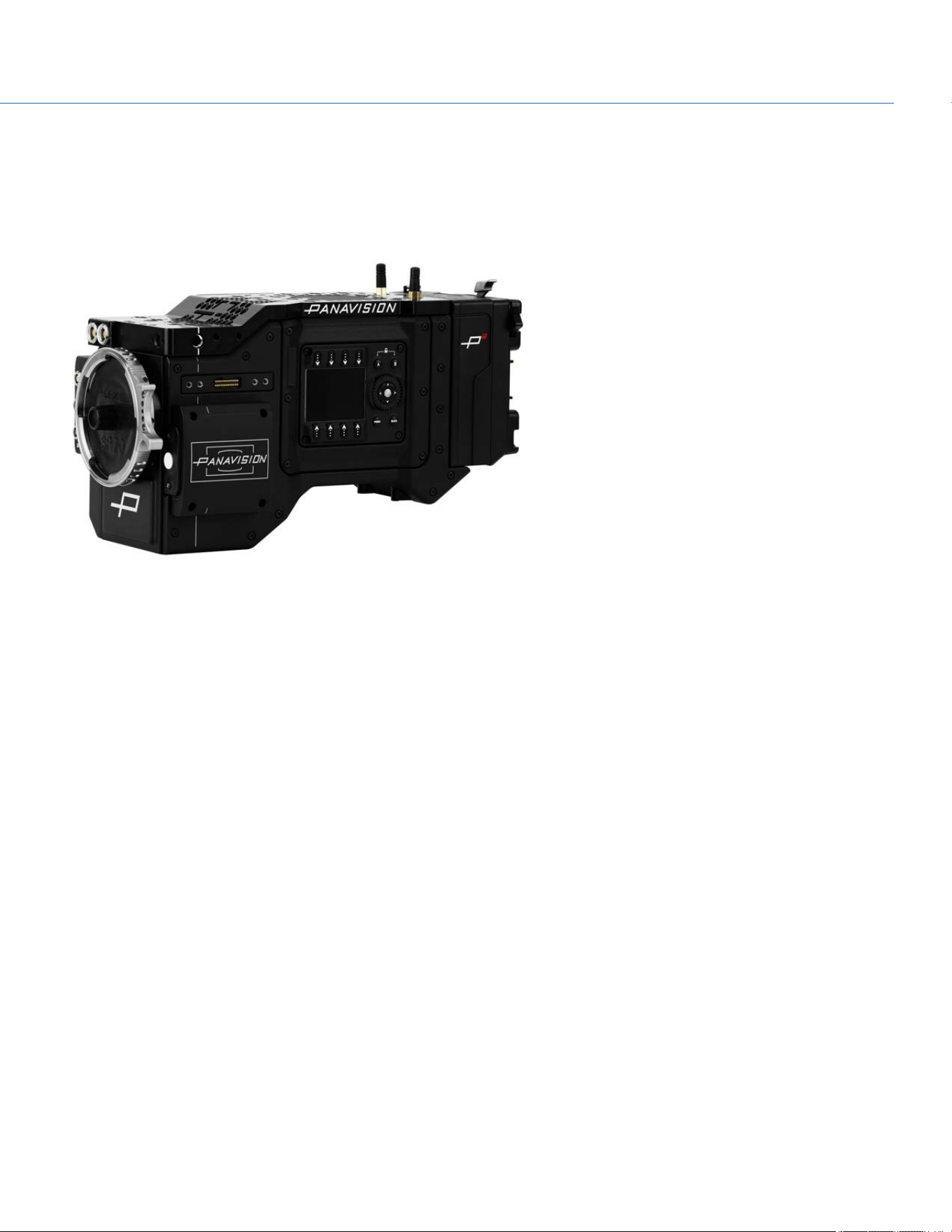
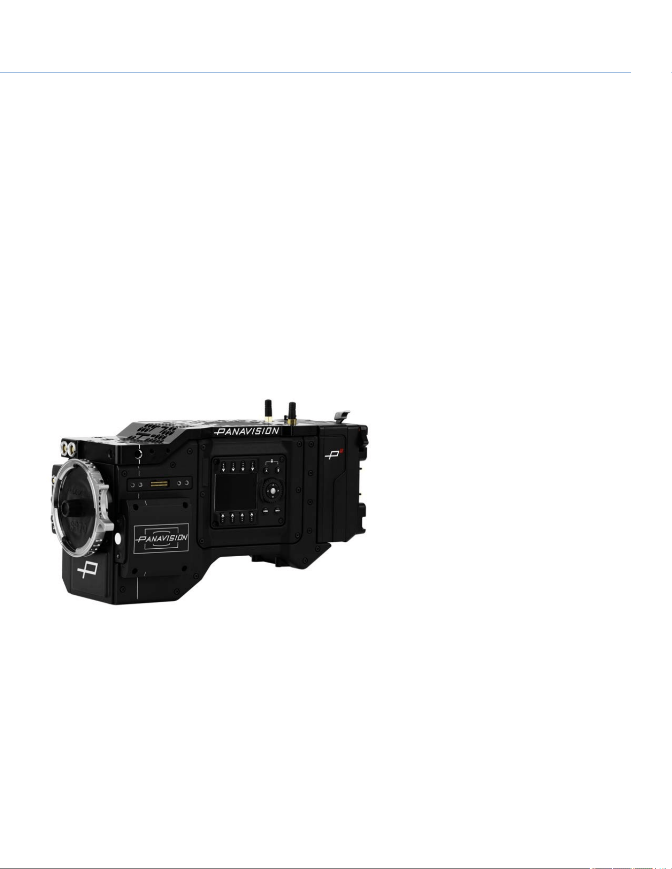
The Panavision Millennium DXL2 is a revolutionary digital camera from Panavision. The large-format sensor captures images
at up to 8K. The camera incorporates the unique Light Iron Color 2 color science, which is compatible with all popular gamuts
and transfer curves.
Figure: Panavision Millennium DXL2
R3D FILE FORMAT AND REDCODE
All videos and frames are recorded to the R3D
®
file format. The R3D file format was developed by RED to provide an
efficient and manageable RAW video data format that promotes advanced post production editing capabilities. In the R3D file
format, the digital image received from the sensor is formatted as a pixel-defect corrected (but in all other aspects
unprocessed) 16-bit per pixel RAW data frame. Each RAW frame, or sequence of RAW frames in a clip, is compressed using a
proprietary wavelet based REDCODE
®
RAW compression, then stored to a Panavision MINI-MAG.
RAW data is recorded independently of any RGB domain color processing such as ISO, White Balance, or other RGB color
space settings. Instead, color parameters are saved as reference metadata; that is, color is not burned into the recorded RAW
data. This recording technique promotes flexibility in RGB color processing, which can be deferred to post production or
adjusted in the field, without affecting the recorded RAW data image quality or dynamic range.
REDCODE is a visually lossless, wavelet-based compression codec that reduces R3D RAW files into a manageable size,
allowing longer recording times on media. The ability to compress RAW data is one of the significant technologies that RED
has brought to the industry.
POST PRODUCTION
DXL2 R3D files are able to be processed in any application that utilizes the RED SDK. 3D LUT transforms to various popular
color spaces and gammas are available for download. For further information and on post production workflow please visit the
Panavision website.
COP YRIGHT © 2020 PA N A VISION IN TERN ATION AL, L.P . FW : V-1.0.0| 8
PANAVISION MILLENNIUM DXL2
CAMERA SYSTEM COMPONENTS
NOTE: Availability of components listed in this chapter is subject to change at any time.
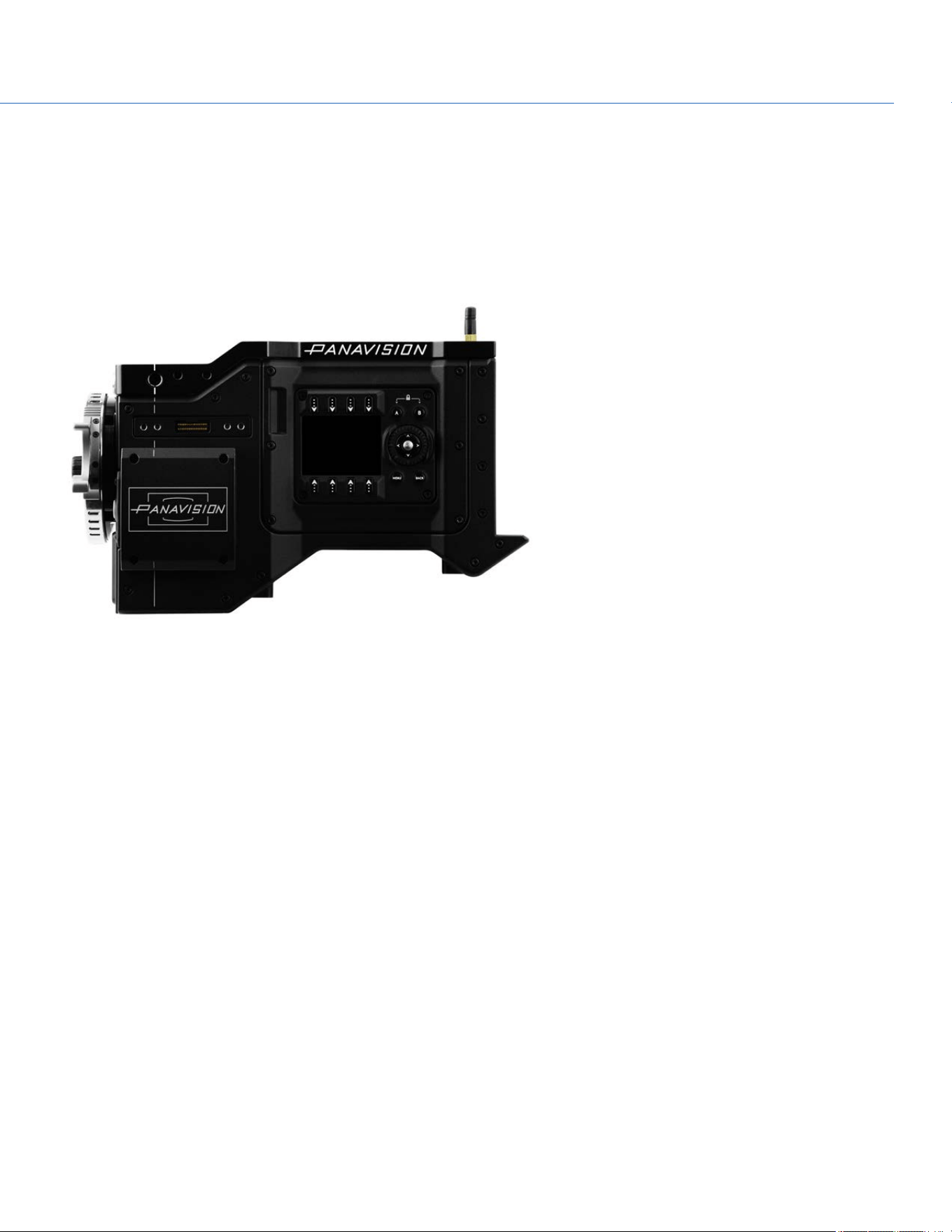
CAMERA BODY
For more information on connectors, go to "Input/Output Connectors" on page138.
Figure: Panavision Millennium DXL2 Body
CAMERA BODY CONTROLS
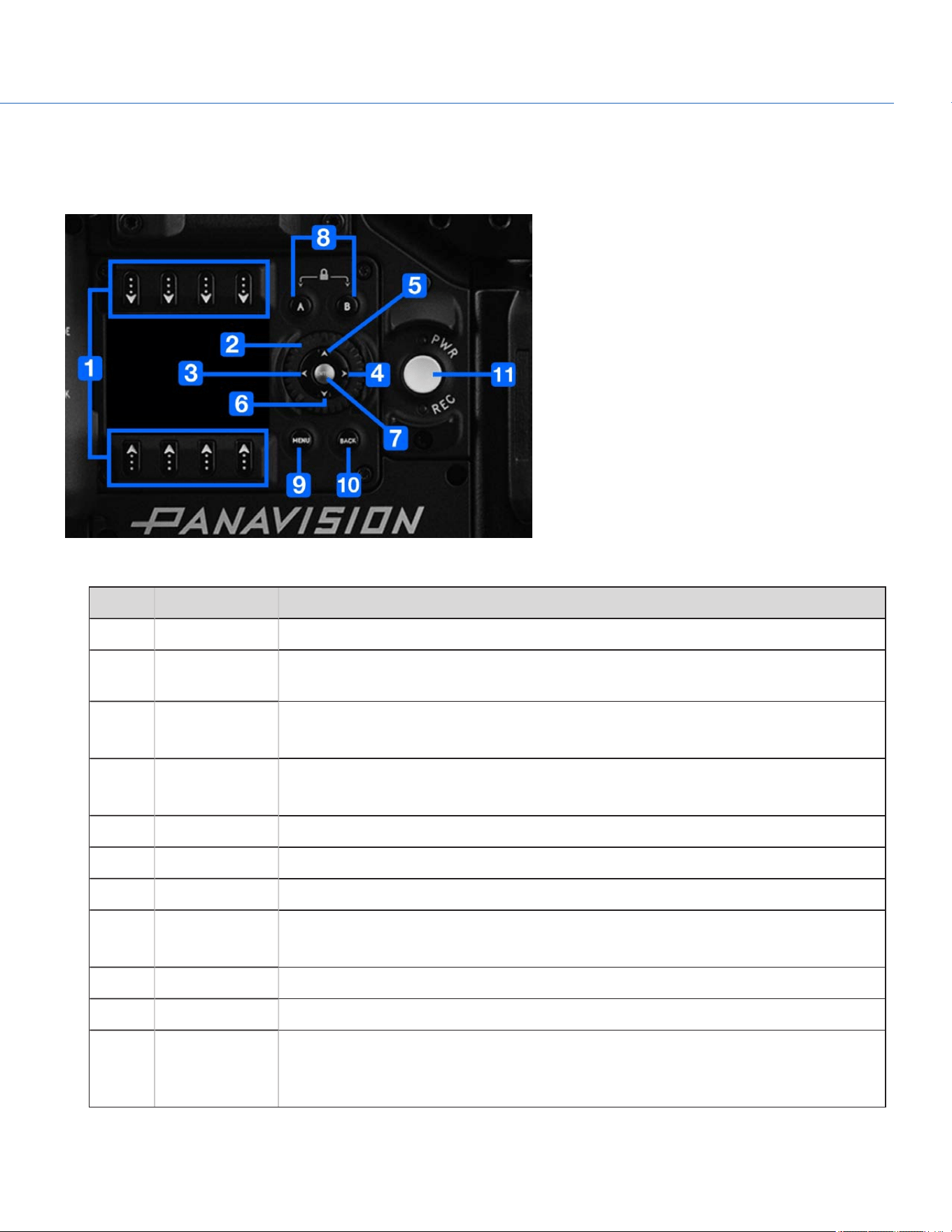
RIGHT SIDE (ASSISTANT SIDE) CONTROLS
Figure: Panavision Millennium DXL2 Controls, Right Side (Assistant Side)
# CONTROL DESCRIPTION
1 Selection keys Select an option or open a shortcut (when available)
2 Navigation
Wheel
Move cursor up/down
3 Nav West Move cursor left
Return to the last menu
4 Nav East Move cursor right
Select menu
5 Nav North Move cursor up
6 Nav South Move cursor down
7 Nav Enter Navigation: Select
8 Assistant A
Assistant B
Programmable keys
Assistant A + Assistant B: Toggle lock/unlock all keys on Assistant Side
9 Menu Access/Exit menus
10 Back Return to the last menu
11 PWR/REC Key Fully press and hold the PWR/REC key for two (2) seconds to turn on/off.
When the camera is on, fully press and then release the PWR/REC key to toggle record
start/stop.
For more information, go to "Default Key Functions" on page150.
COP YRIGHT © 2020 PA N A VISION IN TERN ATION AL, L.P . FW: V-1.0.0| 9
PANAVISION MILLENNIUM DXL2
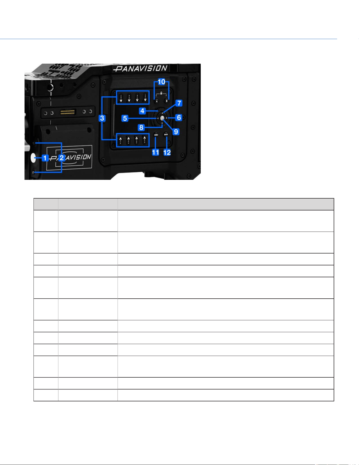
LEFT SIDE (OPERATOR SIDE) CONTROLS
Figure: Panavision Millennium DXL2 Controls, Left Side (Operator Side)
# CONTROL DESCRIPTION
1 REC button Programmable key
Full Press: Record Toggle
2 User Key 1
User Key 2
Programmable keys
User Key 1 + 2 Press: Eject Media
3 Selection keys Select an option or open a shortcut (when available)
4 Navigation Wheel Move cursor up/down
5 Nav West Move cursor left
Return to the last menu
6 Nav East Move cursor right
Select menu
7 Nav North Move cursor up
8 Nav South Move cursor down
9 Nav Enter Navigation: Select
10 Operator A
Operator B
Programmable keys
Operator A + Operator B: Toggle lock/unlock all keys on Operator Side
11 Menu Access/Exit menus
12 Back Return to the last menu
COP YRIGHT © 2020 PA N A VISION IN TERN ATION AL, L.P . FW : V-1.0.0| 10
PANAVISION MILLENNIUM DXL2
CAMERA BODY LEDS
RIGHT SIDE (ASSISTANT SIDE) LEDS
Figure: Panavision Millennium DXL2 LEDs, Right Side (Assistant Side)
NOTE: When the camera is powered only by battery and not AC power, the Power Status LED (PWR) does not turn on. You
can press the button on the battery to check the battery charge level.
COP YRIGHT © 2020 PA N A VISION IN TERN ATION AL, L.P . FW : V-1.0.0| 11
PANAVISION MILLENNIUM DXL2
# LED COLOR/FLASHING DESCRIPTION
1 DC-IN Off No DC power present
Green DC power present
2 Power Status LED (PWR) Off Camera off
1
Green Camera on
Amber flashing Camera on; 5 to 10 min of battery time available
Amber Camera booting
Red flashing Camera on; < 5 min of battery time available
Red Camera shutting down
3 Record Status LED (REC) Off No media present
Green Ready to record
Amber Finalizing
Red flashing (slow) Media mounted with > 5% and ≤ 10% of media
space available
Red flashing (fast) Media mounted with ≤ 5% of media space
available
Red Recording
N/A Power Status LED (PWR) and Record
Status LED (REC)
Both green
flashing
Firmware update in progress
Both red flashing Firmware update error
1. To prevent battery drain, the PWR LED does not illuminate when the camera is off and a power source is present.
COP YRIGHT © 2020 PA N A VISION IN TERN ATION AL, L.P . FW : V-1.0.0| 12
PANAVISION MILLENNIUM DXL2
LEFT SIDE (OPERATOR SIDE) LEDS
Figure: Panavision Millennium DXL2 LEDs, Left Side (Operator Side)
# LED COLOR/FLASHING DESCRIPTION
1 Media Status LED (Back of media
bay)
Off No media mounted
Green Preview; media mounted with > 10% of media space
available
Amber Record finalizing or playback mode
Amber flashing
(slow)
Formatting media
Red flashing (slow) Media mounted with > 5% and ≤ 10% of media space
available
Red flashing (fast) Media mounted with ≤ 5% of media space available
Red Recording; media mounted with > 10% of media space
available
2 Record Status LED
1
Off Not recording, or media not mounted
Red Recording
1. For more information on how to enable/disable this LED, go to "Indicator" on page99. If media is not mounted, this LED is off.
MEDIA
The following SSDs are compatible with the Panavision Millennium DXL2:
ITEM PV
PRODUCTTYPE
Panavision MINI-MAG 512GB
DXLM512
Panavision MINI-MAG 1TB DXLM1
COP YRIGHT © 2020 PA N A VISION IN TERN ATION AL, L.P . FW : V-1.0.0| 13
PANAVISION MILLENNIUM DXL2
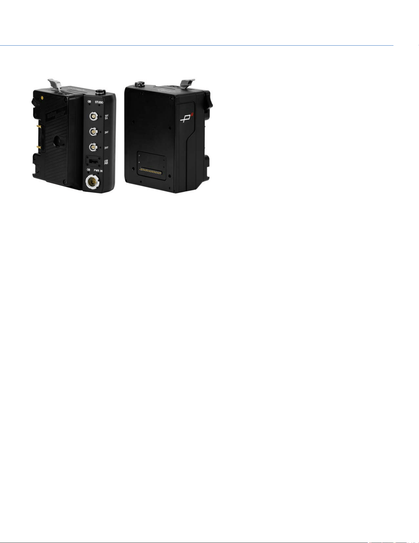
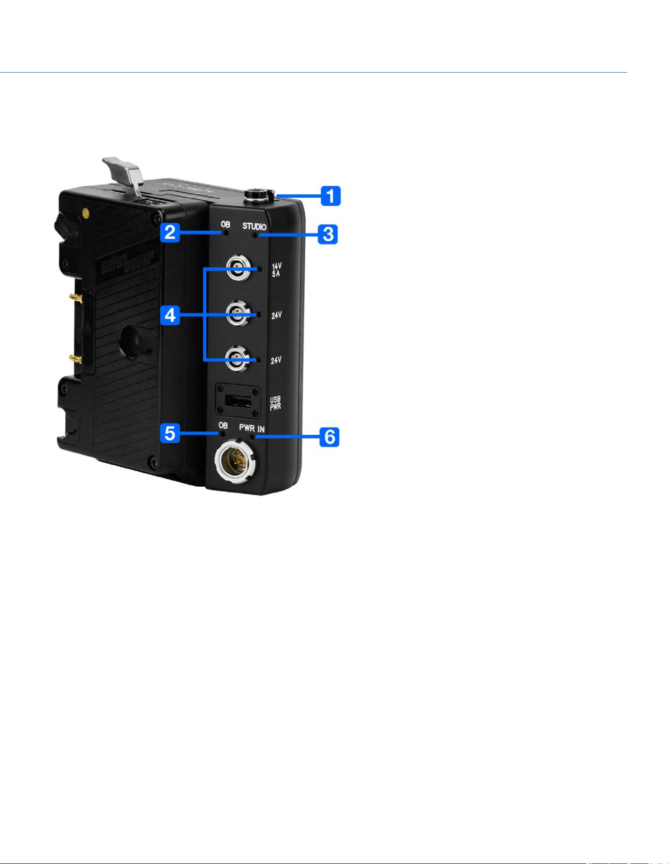
DXL HOT SWAP MODULE
Figure: DXL Hot Swap Module
The DXL Hot Swap Module (Product Code: DXLHS) mounts to the rear of the Panavision Millennium DXL2 (using a Panavision
Adaptor Plate) and supports Anton Bauer Gold Mount batteries. The DXL Hot Swap Module offers multiple power out ports for
accessories and an additional PWR IN (Studio In) port. The power out ports on the DXL Hot Swap Module provide a combined
14V power out (combined 10 A max current) when the module is receiving power.
The battery plate slides up and down the module, and can be locked into any position on the slide. The highest position is
ideal for studio shoots, and the lowest position is ideal for hand-held shoots.
COP YRIGHT © 2020 PA N A VISION IN TERN ATION AL, L.P . FW : V-1.0.0| 14
PANAVISION MILLENNIUM DXL2
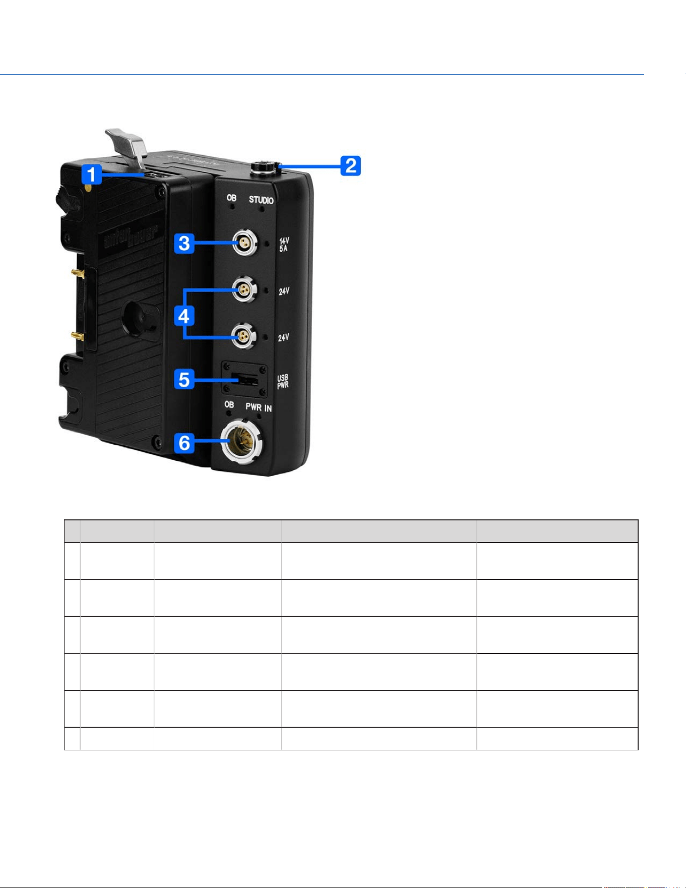
DXL HOT SWAP MODULE CONNECTIONS
Figure: DXL Hot Swap Module
# CONNECTOR CONNECTORTYPE CONNECTORFUNCTION DETAILS
1 P-Tap P-Tap Power out "P-Tap Connector" on the next
page
2 14V 2-pin 0B LEMO Power out; protected by a spring-
loaded cover
"14V Aux Power Out" on the
next page
3 14V, 5A 2-pin 0B LEMO Power out "14V, 5A Aux Power Out" on
page17
4 24V Fischer 3-pin 102 Power out "24V Aux Power Out" on
page17
5 USBPWR USB 2.0, Type A (power
only)
USBpower out "USB PWR" on page17
6 PWR IN 4-pin 2B LEMO Power in (studio in) "PWR IN (Studio In)" on page18
COP YRIGHT © 2020 PA N A VISION IN TERN ATION AL, L.P . FW : V-1.0.0| 15
PANAVISION MILLENNIUM DXL2
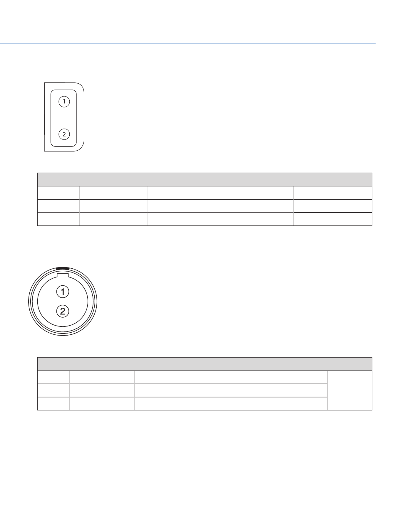
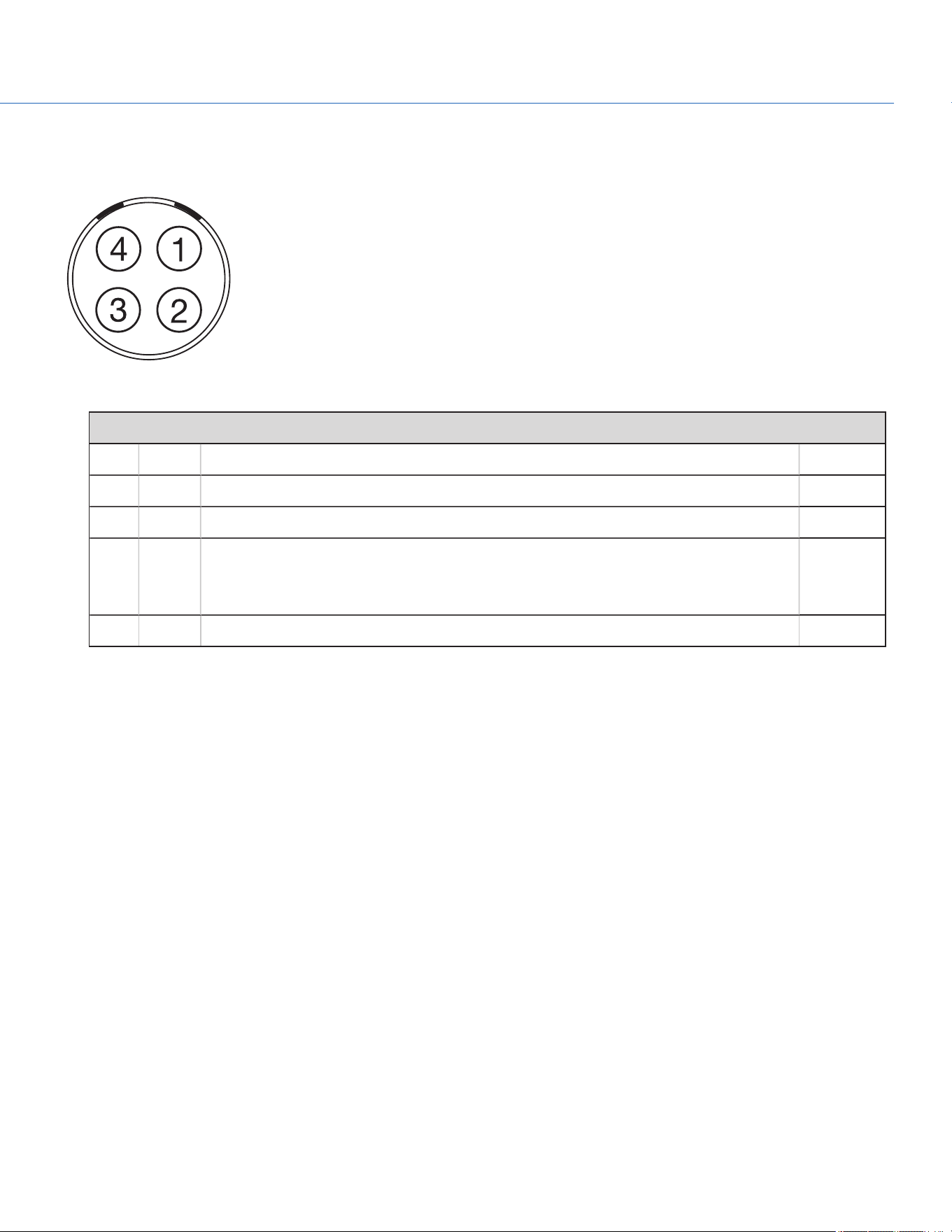
P-TAP CONNECTOR
The DXL Hot Swap Module offers one (1) P-Tap connector that provides power (14V, 10A max) for camera accessories.
Figure: P-Tap Connector (Looking at Camera)
2-PIN P-TAP CONNECTOR
PIN SIGNAL DESCRIPTION DIRECTION
1 GROUND Common ground N/A
2 14V 14V Out
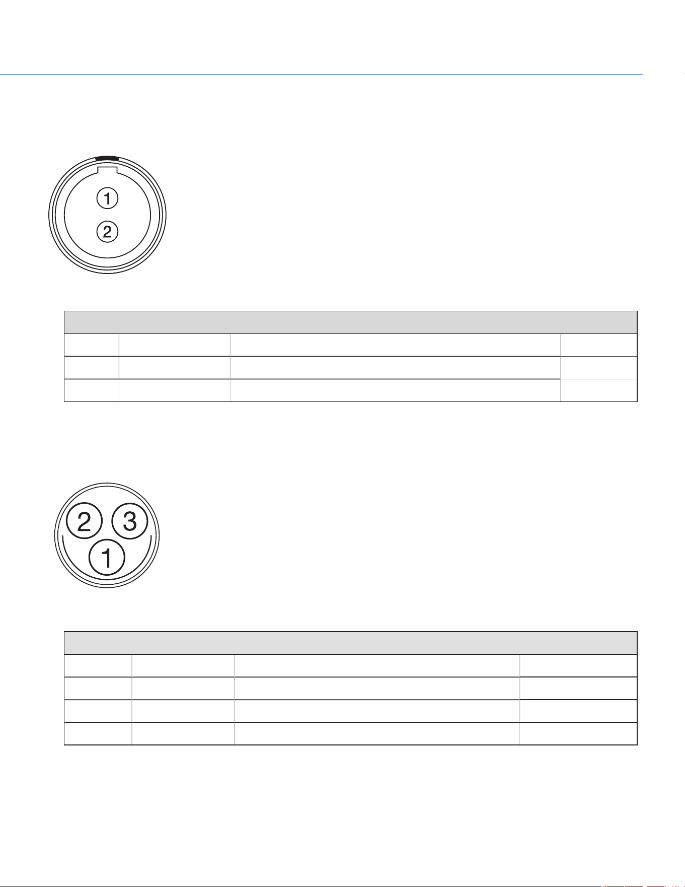
14V AUX POWER OUT
The 2-pin 0B LEMO connector (LEMO EEG.0B.302.CLL) supplies unregulated (+) 11.5 to 17V DC battery pass-through power.
The maximum sustained current draw is 3.0A.
Figure: Front Face of Connector (Looking at the Camera)
LEMO EEG.0B.302.CLL CONNECTOR
PIN SIGNAL DESCRIPTION DIRECTION
1 GROUND Common ground N/A
2 +11.5 to +17V DC +11.5 to 17V DC unregulated battery pass-through power Out
NOTE: Mating connector is FGG.0B.302.CLAD.
COP YRIGHT © 2020 PA N A VISION IN TERN ATION AL, L.P . FW : V-1.0.0| 16
PANAVISION MILLENNIUM DXL2
14V, 5A AUX POWER OUT
The 2-pin 0B LEMO connector (LEMO EEG.0B.302.CLL) supplies unregulated (+) 11.5 to 17V DC battery pass-through power.
The maximum sustained current draw is 5.0A.
Figure: Front Face of Connector (Looking at the Camera)
LEMO EEG.0B.302.CLL CONNECTOR
PIN SIGNAL DESCRIPTION DIRECTION
1 GROUND Common ground N/A
2 +11.5 to +17V DC +11.5 to 17V DC unregulated battery pass-through power Out
NOTE: Mating connector is FGG.0B.302.CLAD.
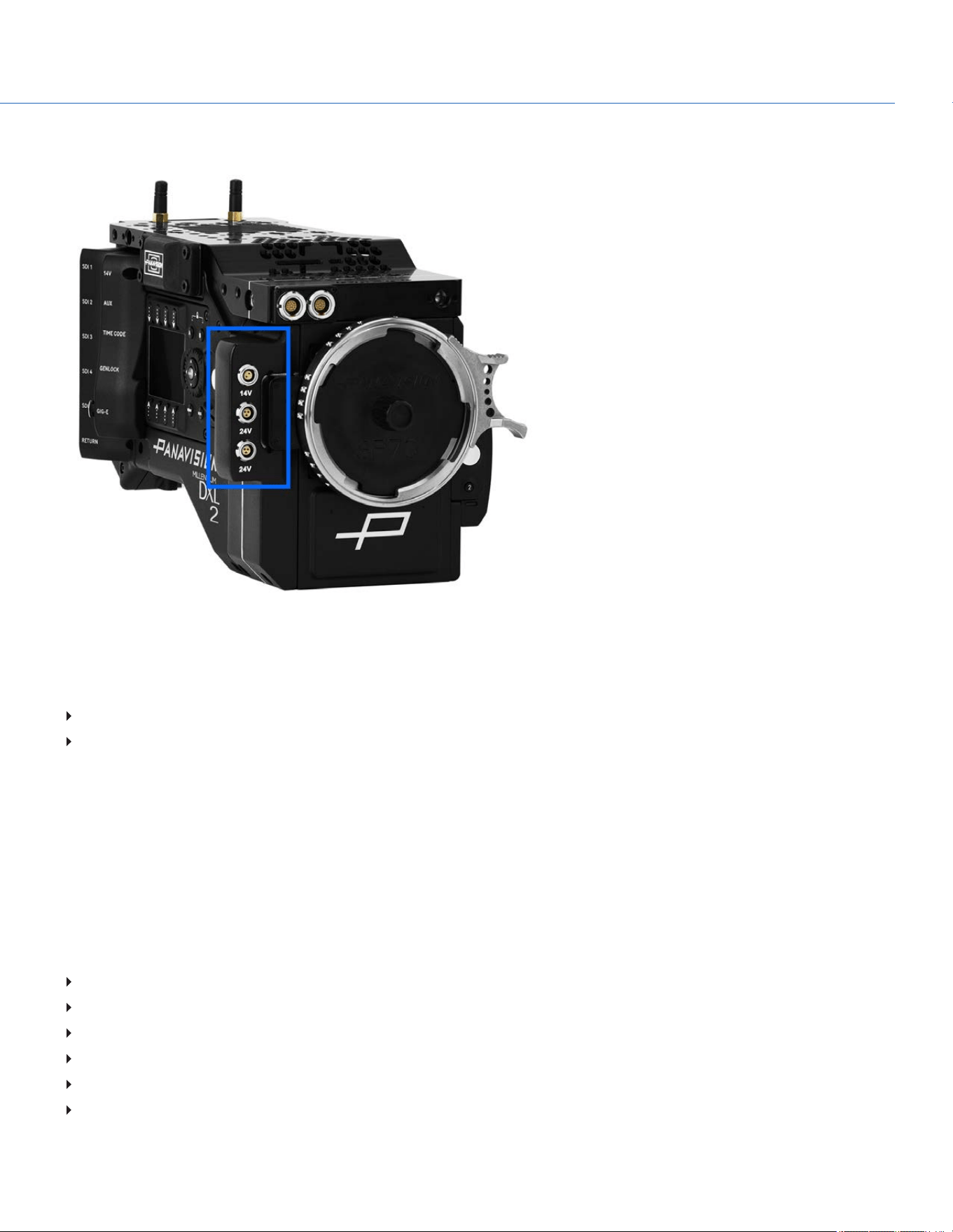
24V AUX POWER OUT
The two (2) Fischer connectors (DG 102 A052-130) up convert from 12V to 24V.
Figure: 24V Connector (Looking at the Camera)
FISCHER 3-PIN CONNECTOR
PIN SIGNAL DESCRIPTION DIRECTION
1 GROUND Common ground N/A
2 24V 24V Out
3 Trigger Active Low to start/stop record In
USB PWR
The USB power-out connector supplies 5V of power. The maximum sustained current draw is 1.5A.
NOTE: The USB connector only offers power out, and does NOT support USB communication.
COP YRIGHT © 2020 PA N A VISION IN TERN ATION AL, L.P . FW : V-1.0.0| 17
PANAVISION MILLENNIUM DXL2
PWR IN (STUDIO IN)
The 4-pin 2B LEMO connector (LEMO EGJ.2B.304.CLA) accepts DC input power from 11.5V DC to 17V DC.
Figure: Front Face of the Connector (Looking at the Camera)
LEMO EGJ.2B.304.CLA CONNECTOR
PIN SIGNAL DESCRIPTION DIRECTION
1 14V VBATT (11.5 TO 18V DC) @ 9A In
2 Ground Common ground N/A
3 28V VBATT (18 to 30V DC) @ 3A
Exclusively powers attached accessories and lens control devices. Power from this pin
does NOT power the camera.
In
4 Ground Common ground N/A
NOTE: Mating connectors are FGJ.2B.304.CLLD62Z and FGJ.2B.304.CLLD52.
COP YRIGHT © 2020 PA N A VISION IN TERN ATION AL, L.P . FW : V-1.0.0| 18
PANAVISION MILLENNIUM DXL2
DXL HOT SWAP MODULE LEDS
To prevent battery drain, the LEDs on the DXL Hot Swap Module do not illuminate when the camera is off and a power
source is present.
Figure: DXL Hot Swap Module
COP YRIGHT © 2020 PA N A VISION IN TERN ATION AL, L.P . FW : V-1.0.0| 19
PANAVISION MILLENNIUM DXL2
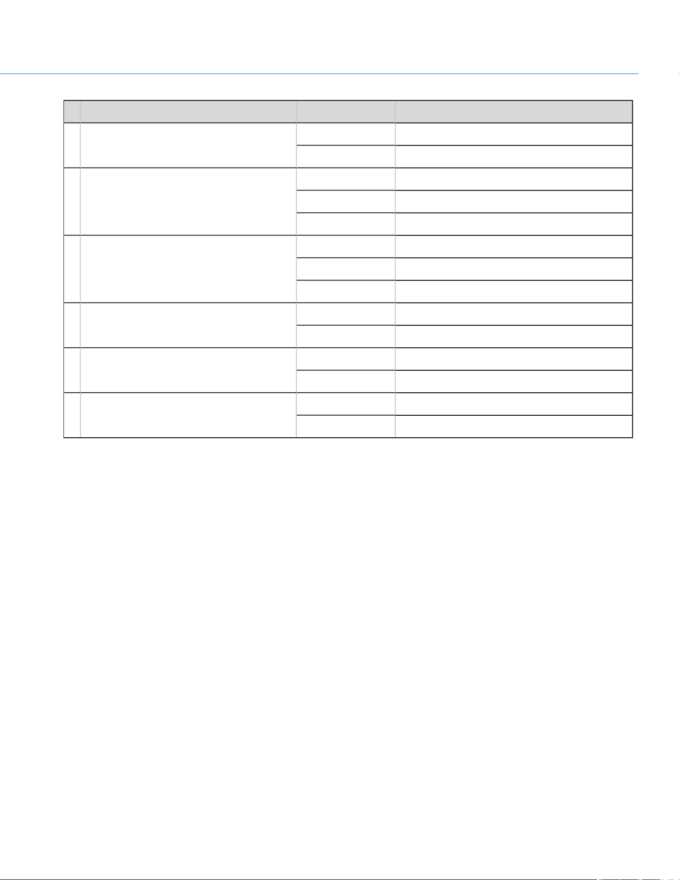
# LED COLOR/FLASHING DESCRIPTION
1 14V Off Module off
Green Port available
2 OB (on-board battery; at top of module) Off Camera is not powered via the on-board battery
Amber Camera is powered via the on-board battery
Flashing Battery power running low
3 Studio
Off Camera is not powered via the PWR INport
Blue Camera is powered via the PWR IN port
Flashing Voltage via the PWRIN port is low
4 14V 5A,
24V
Off Module off
Green Port available
5 OB (on-board battery; at bottom of module) Off Battery is not present
Green Battery is present
6 PWR IN Off Camera is not powered via the PWR INport
Green Camera is powered via the PWR IN port
1. To prevent battery drain, the PWR LED does not illuminate when the camera is off and a power source is present.
COP YRIGHT © 2020 PA N A VISION IN TERN ATION AL, L.P . FW : V-1.0.0| 20
PANAVISION MILLENNIUM DXL2
FIZ MODULE
Figure: FIZ Module
The Panavision Millennium DXL2 features a modular FIZ (focus, iris, zoom) control system. The Panavision Millennium DXL2
initially ships with a native, non-radio FIZ module, the DXLM Module. Panavision also offers additional FIZ modules that are
compatible with third-party systems, including:
Panavision DXLMP Preston FIZ Module
Panavision DXLMC cmotion Module (also compatible with Arri WCU-4 handset)
For more information on connectors for the DXLM Module, go to "Input/Output Connectors" on page138.
LENS MOUNT
The Panavision Millennium DXL2 features a built-in SP70 lens mount, which is compatible with Primo 70 Series lenses. The
lens mount is also compatible with select adaptors that support other lens mounts.
ADDITIONAL COMPONENTS
The Panavision Millennium DXL2 is compatible with additional components including:
Base plate
Jumper block
Third-party FIZ devices
EFV and brackets
Additional modules
Cheese plate and handles
COP YRIGHT © 2020 PA N A VISION IN TERN ATION AL, L.P . FW : V-1.0.0| 21
PANAVISION MILLENNIUM DXL2

COP YRIGHT © 2020 PA N A VISION IN TERN ATION AL, L.P . FW : V-1.0.0| 22
PANAVISION MILLENNIUM DXL2
BASIC OPERATIONS
POWER OPERATIONS
This section describes the basic power operations of the camera system.
POWER PRIORITY
When multiple power sources are connected to the camera, power consumption is prioritized in this sequence:
1. Any power supply connected to the DC IN port on the camera
2. Any power supply connected to Power IN (Studio In) port on the DXL Hot Swap Module
3. Battery mounted to the DXL Hot Swap Module
POWER CONSUMPTION
The camera draws approximately 90W (15V at 6A) when configured with a Primo VF and an SSD.
The camera (via the DC-IN port) also provides approximately 72W (24V @ 3A) exclusively to power attached accessories and
lens control devices. For more information, go to "DC-IN" on page141.
POWER STATUS
The power status of the current primary power source is displayed in the graphical user interface (GUI). Navigate to the Power
In menu at Menu > Maintenance >Power > Power In for the status of all connected power sources.
APPROVED EXTERNAL DC POWER
The camera accepts input voltages of 11.5V to 17V DC, and can draw a maximum current of 9A. The camera can be powered
continuously by connecting one (1) of the following to the DC INport on the camera or attached DXL Hot Swap Module:
GPS (Genesis Power Supply)
S7PS (Super 70 Power Supply)

TURN ON THE CAMERA
NOTE: If you have just turned off the camera, wait at least three (3) seconds before turning the camera back on.
1. Attach a power source to the camera.
The Power Status LED illuminates red, indicating that an appropriate power source is connected.
2. Press and release the PWR/REC key on the right side of the camera.
The Power Status LED illuminates amber as the camera turns on.
The Power Status LED illuminates green to confirm that the camera is turned on and ready to use.
TURN OFF THE CAMERA
Use one of the following methods to turn off the camera:
Press and hold PWR/REC until the Shutting Down... notification shows on the display.
NOTE: The camera turns off automatically if the supply voltage drops to 11.5V.
COP YRIGHT © 2020 PA N A VISION IN TERN ATION AL, L.P . FW : V-1.0.0| 23
PANAVISION MILLENNIUM DXL2
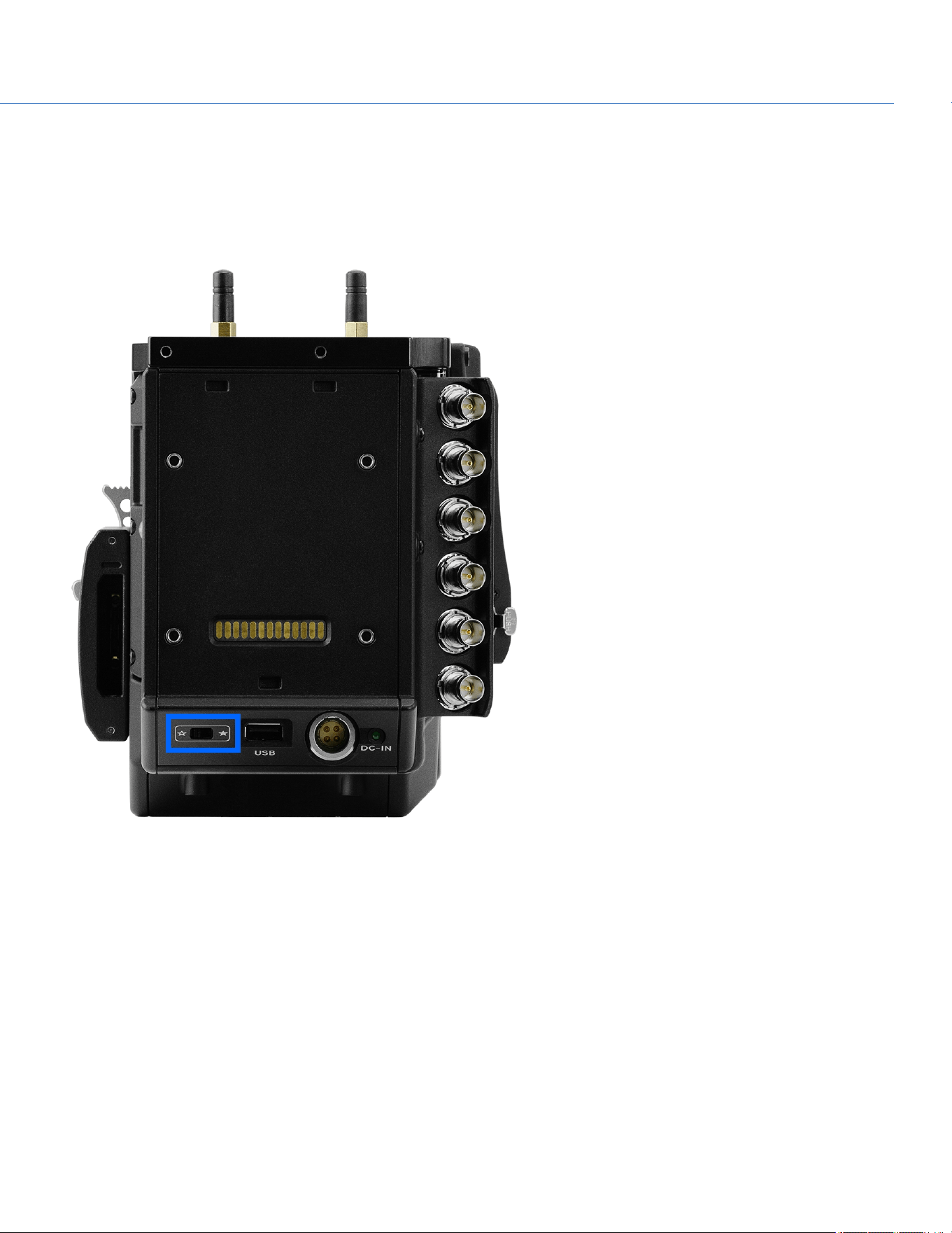
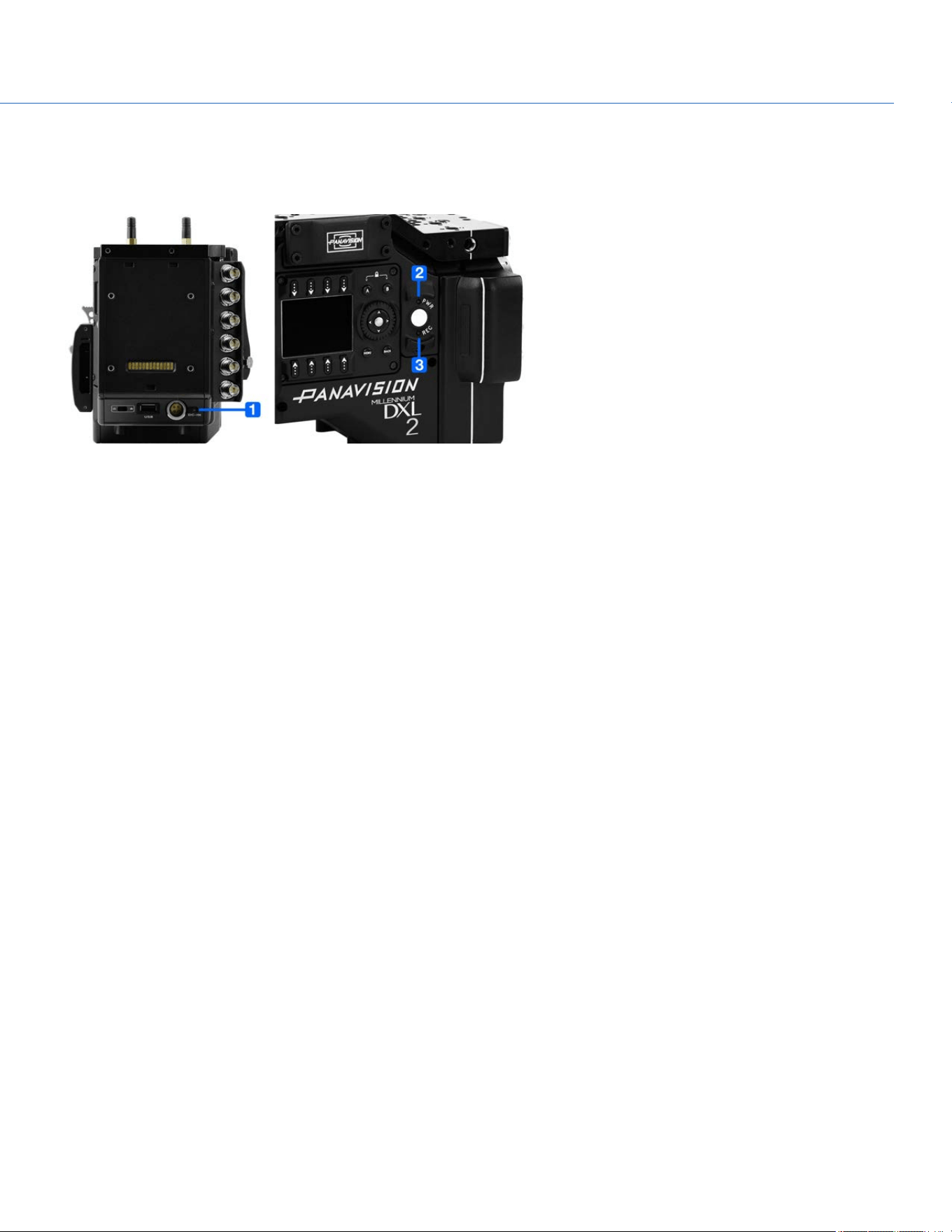
AUTO BOOT ON POWER
The camera features a selector switch that enables the camera to automatically boot when power is provided via the DC IN
connector. The Auto Boot on Power switch (identified by a white star) is located on the back of the camera.
When Auto Boot on Power is enabled, the camera disables all power sources that are not the DC IN connector, including
batteries and the DC IN connectors on any modules.
Figure: Auto Boot on Power Switch
ENABLE AUTO BOOT ON POWER
1. Toggle the Auto Boot on Power switch to On (identified by a white star).
2. Connect a power source to the DC IN connector.
The camera turns on automatically.
3. Turn off the camera by pressing and holding PWR/REC until the Shutting Down... notification shows on the display
NOTE: Simply disconnecting the power source may result in data loss.
COP YRIGHT © 2020 PA N A VISION IN TERN ATION AL, L.P . FW : V-1.0.0| 24
PANAVISION MILLENNIUM DXL2
DISABLE AUTO BOOT ON POWER
1. Toggle the Auto Boot on Power switch to Off (identified by a black star).
The camera will not turn on automatically.
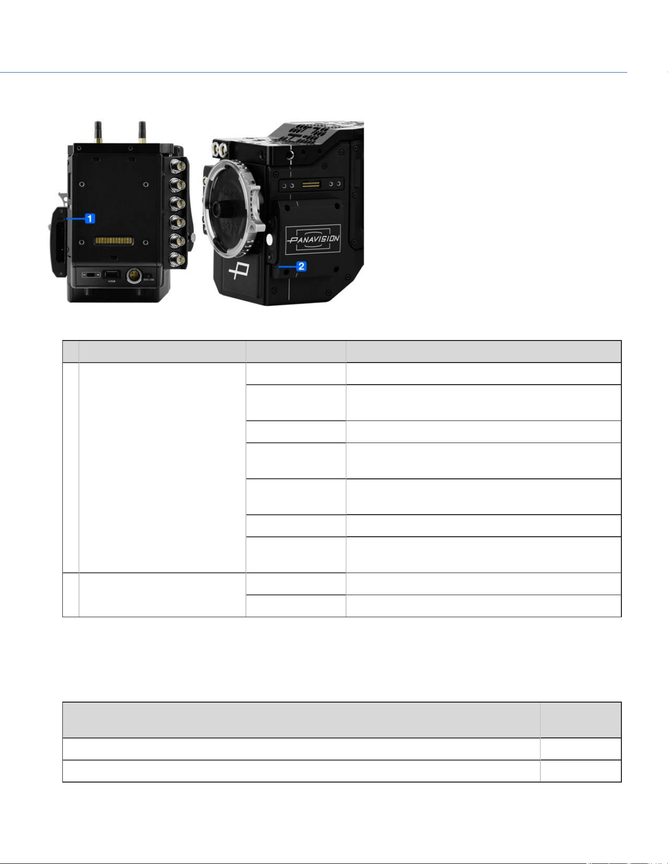
SET UP THE DXL HOT SWAP MODULE
INSTALL A DXL HOT SWAP MODULE
REQUIRED TOOL(S): T20 TORX driver
1. Place the adaptor plate (thin plate) on the back on the Panavision Millennium DXL2.
2. Position the DXL Hot Swap Module against the adaptor plate, aligning the connector on the front of the DXL Hot Swap
Module with the connector on the rear of the camera.
3. Apply pressure and tighten the four (4) captive screws in a cross pattern (“X” pattern) approximately two (2) turns each
using a T20 TORX driver. DO NOT FULLY TIGHTEN.
NOTE: Slide the battery plate down in order to access the top screws, and slide the battery plate up in order to access the
bottom screws. For more information, go to "Slide Battery Plate Up and Down" on the next page.
4. Fully tighten the four (4) screws in a cross pattern (“X” pattern) using a T20 TORX driver.
WARNING: DO NOT OVERTIGHTEN.
Figure: Installed DXL Hot Swap Module
REMOVE A DXL HOT SWAP MODULE
REQUIRED TOOL(S): T20 TORX driver
1. Loosen the four (4) captive screws in a cross pattern (“X” pattern) using a T20 TORX driver.
NOTE: Slide the battery plate down in order to access the top screws, and slide the battery plate up in order to access the
bottom screws. For more information, go to "Slide Battery Plate Up and Down" on the next page.
2. Remove the DXL Hot Swap Module.
3. Remove the adaptor plate.
COP YRIGHT © 2020 PA N A VISION IN TERN ATION AL, L.P . FW : V-1.0.0| 25
PANAVISION MILLENNIUM DXL2

INSTALL GOLD MOUNT BATTERY
1. Install the DXL Hot Swap Module. For more information, go to "Install a DXL Hot Swap Module" on the previous page.
2. Slide the battery onto the DXL Hot Swap Module, ensuring that the Gold Mount T-studs are aligned in the corresponding
slots.
The latch clicks when the battery is installed.
REMOVE GOLD MOUNT BATTERY
1. While holding the battery, push down the black latch on the left side of the DXL Hot Swap Module.
2. Slide the battery to the left to remove the battery.
SLIDE BATTERY PLATE UP AND DOWN
The battery plate slides up and down the module, and can be locked into any position on the slide. The highest position is
ideal for studio shoots, and the lowest position is ideal for hand-held shoots. To slide the battery plate, follow the instructions
below:
1. Move the silver lever at the top of the DXL Hot Swap Module toward the right side (Assistant side) of the camera.
2. Slide the battery plate into the position you want it.
3. To lock the battery plate into place, move the silver lever at the top of the DXL Hot Swap Module toward the left side
(Operator side) of the camera.
COP YRIGHT © 2020 PA N A VISION IN TERN ATION AL, L.P . FW : V-1.0.0| 26
PANAVISION MILLENNIUM DXL2
RECORD
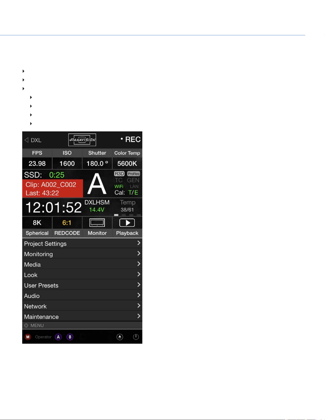
Perform one of the following actions to begin recording:
Press PWR/REC on the camera.
Press REC on the media bay.
Enable record via:
RCP.
GPI through 7-pin AUX port.
3-pin Fischer R/S through front 24V ports.
DXLControl smartphone app (for iOS or Android).
Figure: DXL Control App Interface
COP YRIGHT © 2020 PA N A VISION IN TERN ATION AL, L.P . FW : V-1.0.0| 27
PANAVISION MILLENNIUM DXL2

COP YRIGHT © 2020 PA N A VISION IN TERN ATION AL, L.P . FW : V-1.0.0| 28
PANAVISION MILLENNIUM DXL2
BASIC MENUS AND USER INTERFACE
GUI MENU INTRODUCTION
This section describes the structure and layout of the graphical user interface (GUI) on the operator and assistant side UI's.
Additional advanced menu controls through a touchscreen enable access to edit overlays, presets, and other maintenance
level settings.
The Operator and Assistant Side UIs each have up to four (4) pages that you can scroll through by using the Left and Right
arrows. These pages are:
Home Page: This is the page that displays when the camera turns on, and displays recording information and project
settings. This page cannot be toggled on/off. For more information, go to "Home Page" on the next page.
User Page: This page displays recording information, but does not display project settings. Various statuses and shortcuts
can be assigned to this page. For more information, go to "User Page" on page31.
Monitor Page:This page displays the color space, gamma curve, overlays, and LUTs applied to each monitor. For more
information, go to "Monitor Page" on page33.
Audio Page: This page displays audio information. For more information, go to "Audio Page" on page34.
This section describes each page.
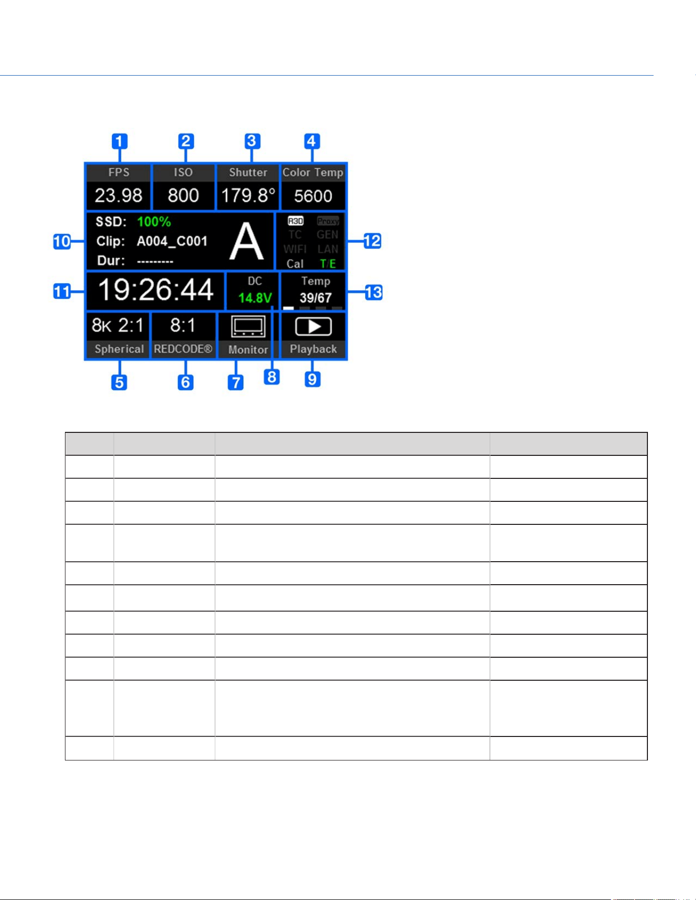
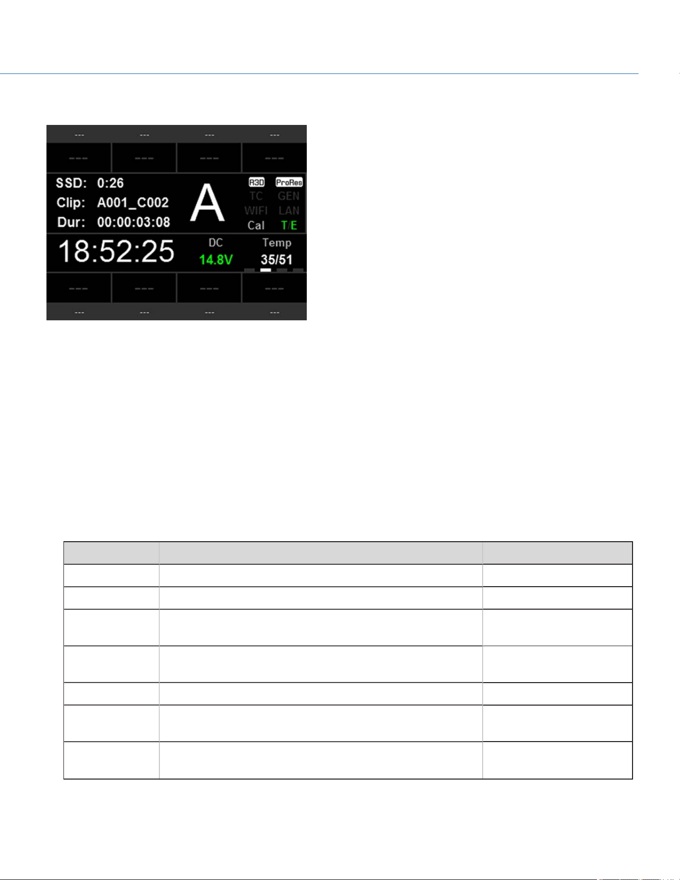
HOME PAGE
Figure: Home Page
# ITEM DESCRIPTION DETAILS
1 Frame Rate (fps) Recording frame rate "Frame Rate" on page51
2 ISO Camera sensitivity "ISO" on page38
3 Shutter Integration time or shutter angle "Exposure/Shutter" on page54
4 Color Temperature White balance and Tint "Color Temperature" on
page37
5 Sensor Resolution Record format (resolution) Resolution
6 REDCODE
®
REDCODE compression setting "REDCODE" on page45
7 Monitor Shortcut to the Monitor page "Home Page" above
8 Power Status DC voltage in or % of remaining battery capacity "Power Status" on page36
9 Playback Shortcut to Playback mode "Playback " on page104
10 Clip Information Standby/Preview mode: Name of next clip; duration of
previous clip.
Record mode: Name and duration of current clip.
N/A
11 Timecode Current timecode value "Timecode" on page55
COP YRIGHT © 2020 PA N A VISION IN TERN ATION AL, L.P . FW : V-1.0.0| 29
PANAVISION MILLENNIUM DXL2
# ITEM DESCRIPTION DETAILS
12
System Status
Indicators
R3D/Proxy "Select Record File Format" on
page50
TC:Timecode
"TC Indicator" on page35
GEN: Genlock
"GEN Indicator" on page35
WIFI: Indicates WiFi connection
"WiFi Indicator" on page35
LAN
"LAN Indicator" on page35
Cal: T/E
"CAL: T/E Indicator" on
page36
13 Temperature Temperature: Camera sensor and electronics
temperature, respectively
"Sensor Calibration" on
page94
COP YRIGHT © 2020 PA N A VISION IN TERN ATION AL, L.P . FW : V-1.0.0| 30
PANAVISION MILLENNIUM DXL2
USER PAGE
Figure: User Page
The information in the middle of the screen is identical to the information displayed on the Home Page. For more
information, go to "Home Page" on page29. You can assign statuses and shortcuts to the eight (8) slots along the top and
bottom of the screen.
CHANGE OR CLEAR ITEMS IN SLOTS ON USER PAGE
To change or clear an item in a slot, follow the instructions below:
1. Press and hold the arrow button on the camera.
2. Select the new item to assign to the slot. To clear the slot, select NONE.
ASSIGN ITEMS TO SLOTS ON USER PAGE
Use the arrow buttons on the camera to assign the following statuses and shortcuts to the slots:
ITEM DESCRIPTION DETAILS
None Slot remains blank N/A
Aperture Aperture of lens N/A
Camera Pitch Angle of camera tilt up or down (measured in degrees; recorded
per frame)
N/A
Camera Roll Angle of camera around central axis from front to back of camera
(measured in degrees; recorded per frame)
N/A
Color Space Default color space. Shortcut to Color Space menu. "Look Menu" on page67
Color
Temperature
Color Temperature. Shortcut to Color Temperature menu. "Color Temperature" on
page37
Fan Speed: 1 Speed of Fan 1 "Temperature and Fan Status"
on page88
COP YRIGHT © 2020 PA N A VISION IN TERN ATION AL, L.P . FW : V-1.0.0| 31
PANAVISION MILLENNIUM DXL2

ITEM DESCRIPTION DETAILS
Fan Speed: 2 Speed of Fan 2 "Temperature and Fan Status"
on page88
Fan: Maximum
Preview Speed
The maximum speed of the fans in preview mode "Fan and Temperature
Management" on page86
Fan: Maximum
Record Speed
The maximum speed of the fans in record mode "Fan and Temperature
Management" on page86
Focal Length Focal length N/A
Focus Distance Focus distance N/A
Focus Distance:
Far
Maximum focal length N/A
Focus Distance:
Near
Minimum focal length N/A
Format Record format (resolution). Shortcut to Resolution menu. Resolution
ISO ISO. Shortcut to ISO menu. "ISO" on page38
LCD Brightness Brightness of the attached LCD. Shortcut to LCD Brightness menu. "LCD Brightness" on page38
Magnify Magnify setting. Shortcut to Magnify menu. "Magnify" on page39
REDCODE REDCODE compression setting. Shortcut to REDCODE menu. "REDCODE" on page45
Frame Rate (fps) Recording frame rate "Frame Rate" on page51
Temperature:
Core
Camera core temperature "Sensor Calibration" on
page94
Temperature:
Sensor
Camera sensor temperature "Sensor Calibration" on
page94
Tools False color mode. Shortcut to Tools menu. "Tools" on page40
COP YRIGHT © 2020 PA N A VISION IN TERN ATION AL, L.P . FW : V-1.0.0| 32
PANAVISION MILLENNIUM DXL2
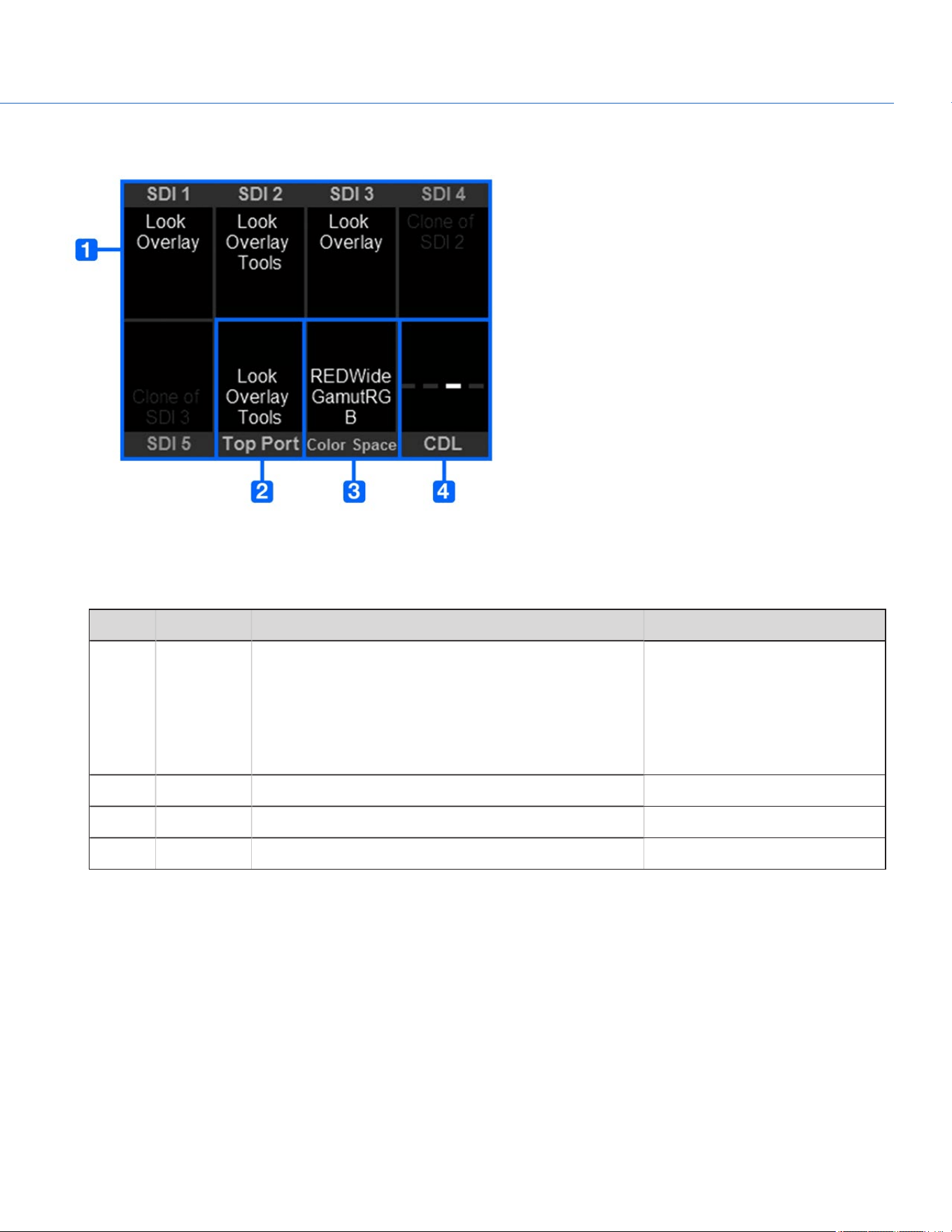
MONITOR PAGE
Figure: Monitor Page
The first six (6) slots along the top and bottom of the screen show the monitor settings for the SDI ports and the Top VF
(viewfinder).
# ITEM DESCRIPTION DETAILS
1 SDI 1
SDI 2
SDI 3
SDI 4
SDI 5
Monitor preferences applied to each SDI out port "Monitor Preferences" on page57
2 Top Port Monitor preferences applied to the top 16 pin serial port "Monitor Preferences" on page57
3 Color Space Output color space "Look Menu" on page67
4 CDL Shortcut to CDL menu "Look Menu" on page67
COP YRIGHT © 2020 PA N A VISION IN TERN ATION AL, L.P . FW : V-1.0.0| 33
PANAVISION MILLENNIUM DXL2
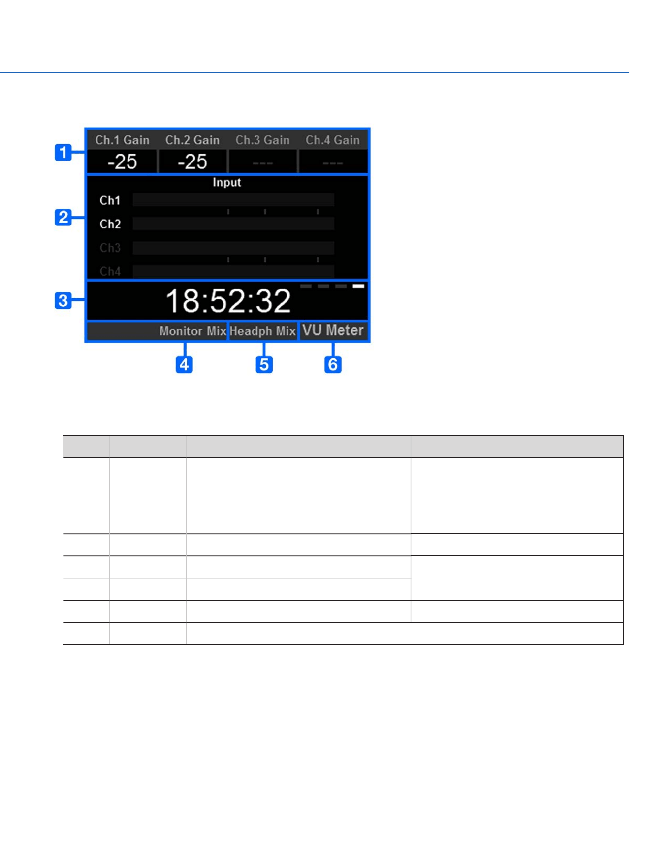
AUDIO PAGE
Figure: Audio Page
The Audio Page displays audio information from the internal microphone and any attached audio modules.
# ITEM DESCRIPTION DETAILS
1 Ch. 1 Gain
Ch. 2 Gain
Ch. 3 Gain
Ch. 4 Gain
Gain level for each audio channel "Pre-Amp Gain" on page109
2 Input Volume for each audio channel "Audio Meter (VU Meter)" on page112
3 Timecode Current timecode value "Timecode" on page55
4 Monitor Mix Shortcut to the Monitor Mix "Monitor Mix" on page110
5 Headph Mix Shortcut to the Headphone Mix N/A
6 VU Meter Toggle between Input and Output levels "Audio Meter (VU Meter)" on page112
COP YRIGHT © 2020 PA N A VISION IN TERN ATION AL, L.P . FW : V-1.0.0| 34
PANAVISION MILLENNIUM DXL2

MENUS ONLY ACCESSIBLE VIA HOME AND USER PAGES
This section describes the status indicators and menus that are only accessible via the Home and User Pages.
SYSTEM STATUS INDICATORS
This section describes the colors and behavior of the System Status indicators in the Home Page.
TC INDICATOR
The TC indicator shows the current timecode status.
Gray: No analog timecode is detected.
Red: Analog timecode is detected but not enabled.
Green: Analog timecode is used to jam the time of day timecode.
For more information, go to "Timecode, Genlock, Multi-Camera Setup" on page114.
WIFI INDICATOR
The WiFi indicator shows the WiFi status.
Gray: WiFi is disabled.
Yellow: WiFi is not connected.
Green: WiFi is enabled.
For more information, go to "WiFi" on page80.
GEN INDICATOR
The GEN indicator shows the current genlock status.
Gray: No genlock signal is detected, or the signal cannot cross-lock to project (24.00 fps vs. 23.98 fps).
Red: During process of sync, or genlock is lost while recording.
Green: A genlock signal matching the current HD-SDI monitor rate is locked.
Yellow: Timing is cross-locked to compatible but not matching monitor rate. For example, genlock is 24.00 fps, and HD-
SDI monitor rate is 25.00 fps.
NOTE: When the GEN indicator is yellow, DO NOT perform 3D operation. This warns that genlock source settings and camera
settings are not aligned, so phasing of the sync between cameras is not guaranteed.
For more information, go to "Timecode, Genlock, Multi-Camera Setup" on page114.
LAN INDICATOR
The LAN indicator shows the current status of an external LAN connection through the Gig-E port.
Gray: External control of the camera is not enabled.
Green: Ethernet is enabled.
COP YRIGHT © 2020 PA N A VISION IN TERN ATION AL, L.P . FW : V-1.0.0| 35
PANAVISION MILLENNIUM DXL2

CAL: T/E INDICATOR
The CAL: T/E indicator shows changes to temperature (T) or exposure (E) in relation to the active calibration map. If the
temperature or exposure changes significantly, calibrate the sensor at the desired temperature and exposure. Failure to
properly calibrate the sensor may reduce image quality.
Green: Sensor temperature or exposure are properly calibrated for current settings.
Yellow: Slight change in sensor temperature or exposure.
Red: Significant change in sensor temperature or exposure.
The – and + indicate whether the sensor temperature or exposure has decreased or increased, respectively.
NOTE: T and E indicators change colors independently of each other.
POWER STATUS
The Power Status element displays the current supply voltage or remaining battery capacity.
DC IN SUPPLY VOLTAGE
When powering the camera via DC power, the current voltage displays. When powering the camera using batteries, the
remaining battery capacity displays. The remaining capacity is indicated by the following colors:
Green: 12.0V and up
Yellow: 11.8V to 11.9V
Red: 11.6V to 11.7V
NOTE: The camera turns off automatically if the supply voltage drops to 11.5V.
COP YRIGHT © 2020 PA N A VISION IN TERN ATION AL, L.P . FW : V-1.0.0| 36
PANAVISION MILLENNIUM DXL2
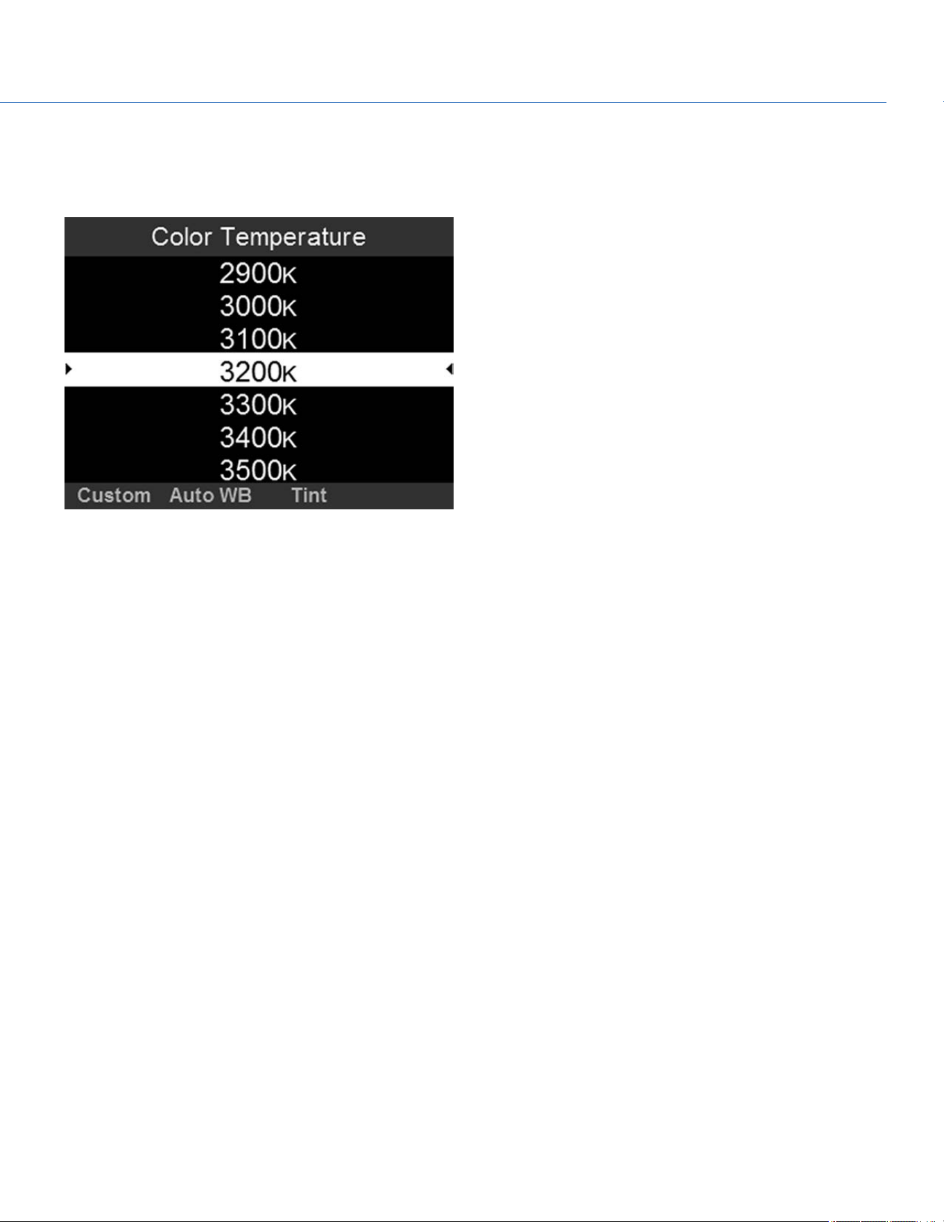
COLOR TEMPERATURE
To access the Color Temperature menu, select Color Temp from the Home Page.
Figure: Color Temperature
Select a color temperature. The range is 1700 to 10,000 KELVIN, and the default is 5600 KELVIN.
TINT
Color temperature calculations assume a pure light source that may not be true in the specific scene the camera is imaging.
To compensate for any residual colorcast, the Tint parameter adjusts the RGB color balance with a compensating magenta-
green color component. Tint range is –100 to 100, with a default of 0.000.
NOTE: Selecting Auto White Balance calculates a new Tint value. The value does not change if you adjust the color
temperature manually. Selecting a preset resets the Tint to 0.000.
AUTO WHITE BALANCE
Auto white balance analyzes the central 25% of the image visible in the monitor to calculate a color temperature that will
render a white object as white.
To use auto white balance, follow the instructions below:
1. Place a white or grey object under the ambient light.
2. Select Color Temp from the Home Page.
3. Select Auto WB.
COP YRIGHT © 2020 PA N A VISION IN TERN ATION AL, L.P . FW : V-1.0.0| 37
PANAVISION MILLENNIUM DXL2
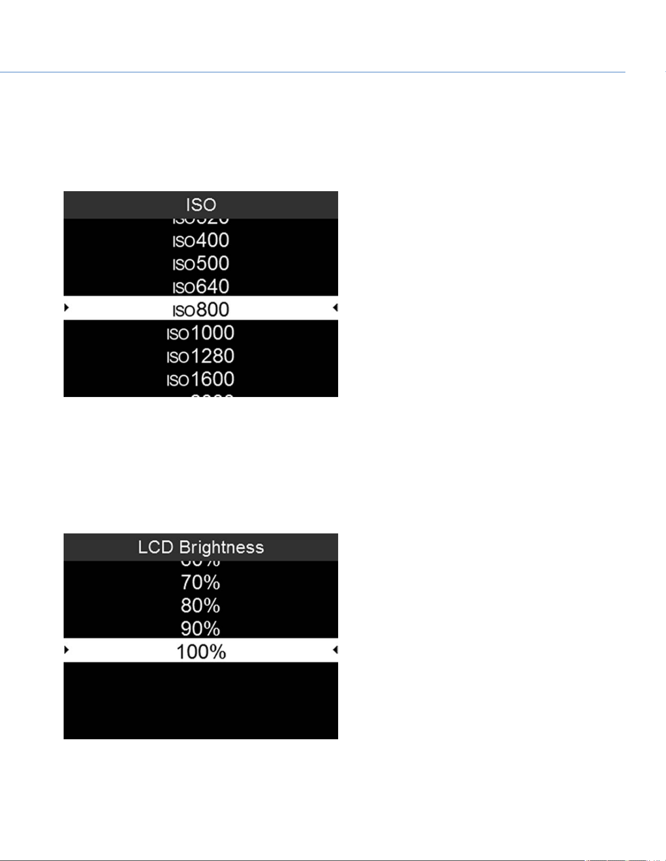
ISO
To set ISO, follow the instructions below:
1. Add ISO to the User Page. For more information, go to "User Page" on page31.
2. Select ISO from the User Page.
3. Select an ISOvalue.
Figure: ISO
LCD BRIGHTNESS
To set the brightness of the Operator and Assistant Side UIs, follow the instructions below:
1. Add LCD Brightness to the User Page. For more information, go to "User Page" on page31.
2. Select LCD Brightness from the User Page.
3. Select a brightness value.
Figure: LCD Brightness
COP YRIGHT © 2020 PA N A VISION IN TERN ATION AL, L.P . FW : V-1.0.0| 38
PANAVISION MILLENNIUM DXL2
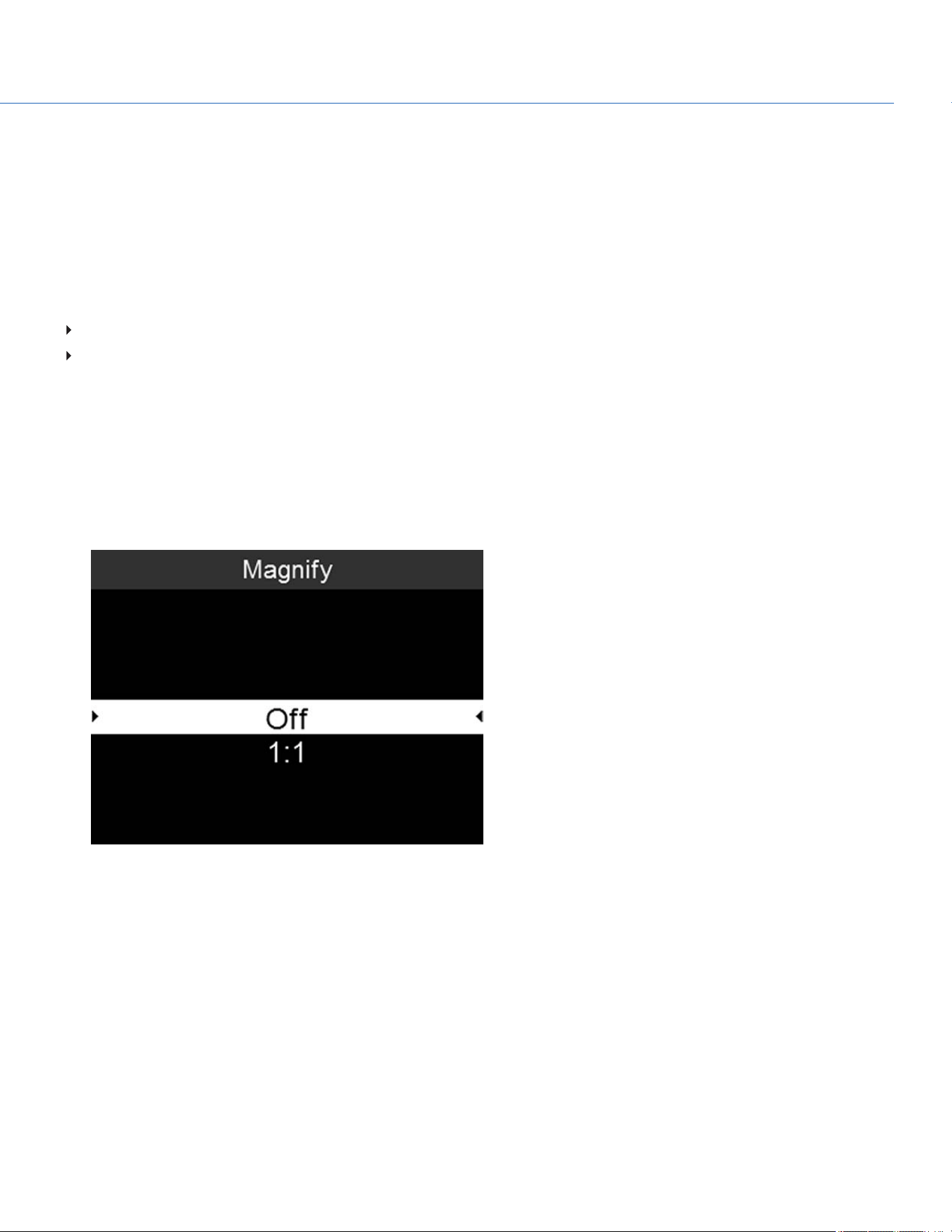
MAGNIFY
The Magnify tool displays the central region of the sensor in 1:1 pixel resolution on an attached monitor. When enabled, the
AF Window and the magnified region display. The AF Window determines the center point of the magnified region. If the lens
or lens mount is not capable of autofocus with the camera, use Confirm mode to turn on the AF Window. Sharpening is
disabled when Magnify mode is enabled. The camera automatically exits Magnify mode when recording begins.
The Magnify tool magnifies a 1920 x 1020 region, centered on a 1920 x 1080 display. If the resolution is lower than 1920 x
1020, the image border cannot be magnified. Use the following equations to determine the area of the image border that will
not be magnified:
Border width: (1920 – W) / 2
Border height: (1020 – H) / 2
NOTE: Frame rate and resolution cannot be modified in Magnify mode.
ENABLE MAGNIFY
To enable Magnify, follow the instructions below:
1. Add Magnify to the User Page. For more information, go to "User Page" on page31.
2. Select Magnify from the User Page.
3. Select 1:1.
Figure: Magnify
COP YRIGHT © 2020 PA N A VISION IN TERN ATION AL, L.P . FW : V-1.0.0| 39
PANAVISION MILLENNIUM DXL2
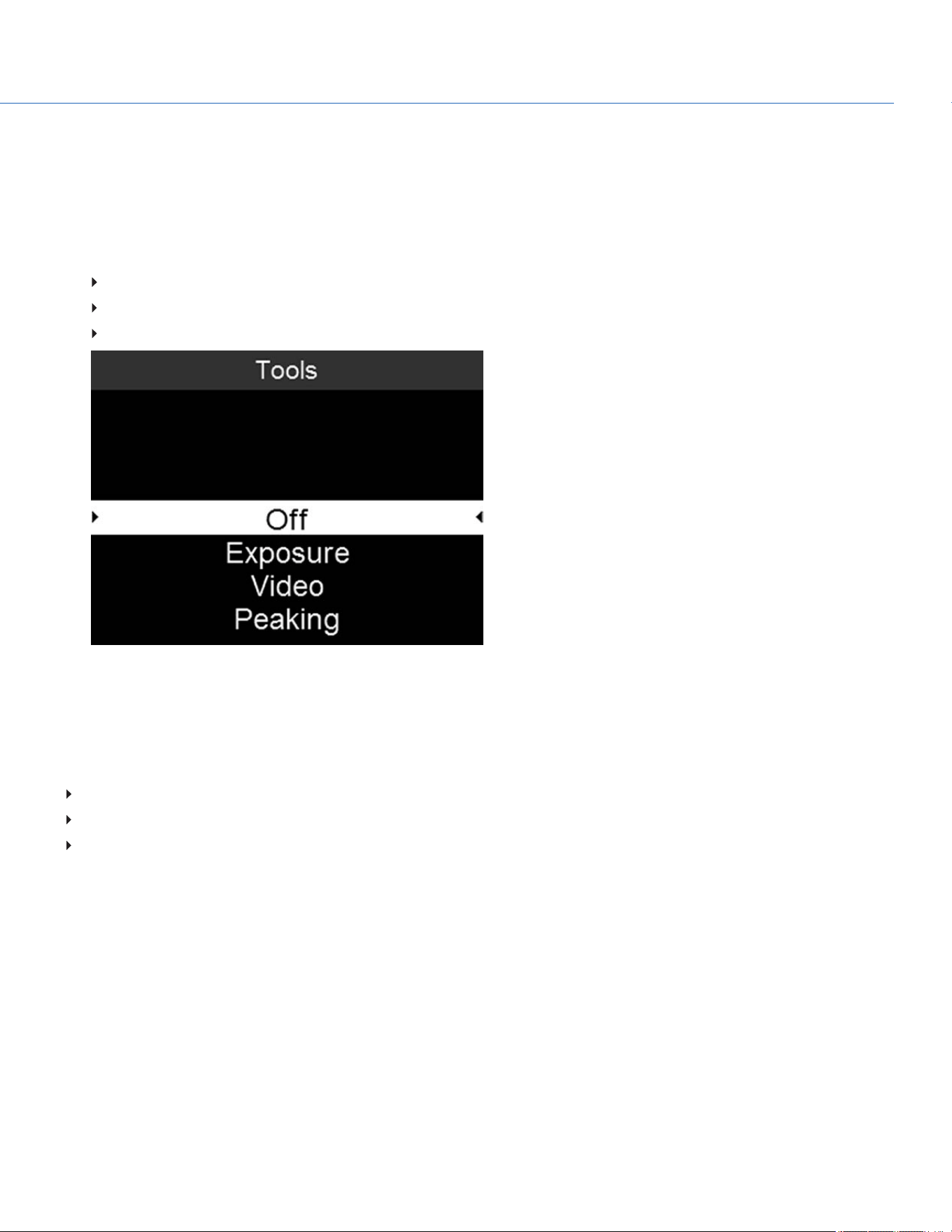
TOOLS
To enable a Tool, follow the instructions below:
1. Add Tools to the User Page. For more information, go to "User Page" on page31.
2. Select Tools from the User Page.
3. Select one of the following:
Exposure:For more information, go to "Exposure" below.
Video: For more information, go to "Video" on the next page.
Peaking: For more information, go to "Peaking" on the next page.
Figure: Tools
EXPOSURE
The Exposure tool displays a color overlay on top of a desaturated image that allows you to check for proper exposure.
The Exposure meter colors indicate the following information:
Purple: Underexposed; indicates sensor exposure levels that may be noisy if gained up in post production.
Green: IRE 41–48; based on the RGB levels of the video out signal and not the RAW data.
Red: Overexposed; indicates sensor exposure levels that are clipping.
Purple (underexposure) and red (overexposure) are based on RAW data and show areas that are clipping or close to clipping.
The RGB settings DO NOT affect the Exposure indicators.
COP YRIGHT © 2020 PA N A VISION IN TERN ATION AL, L.P . FW : V-1.0.0| 40
PANAVISION MILLENNIUM DXL2

VIDEO
The Video tool displays a color overlay that indicates the video level of the RGB monitor path (calibrated to the SMPTE test
signal).
Colors are based on the RGB levels of the video out signal (that is, the “cooked” look, and not RAW data). The RGB settings
affect the Video indicators.
The Video indicators represent the following IRE values (at all other values, the desaturated image represents the luminance
value of the ISO adjusted image):
Purple: IRE 0–4
Blue: IRE 5
Teal: IRE 10–12
Green: IRE 41–48
Pink: IRE 61–70
Straw: IRE 92–93
Yellow: IRE 94–95
Orange: IRE 96–98
Red: IRE 99–100
PEAKING
The Peaking tool emphasizes contrast and edges in the image without changing brightness or image content making it easier
to judge focus. Adjust zoom and focus to easily see which objects are coming into focus.
COP YRIGHT © 2020 PA N A VISION IN TERN ATION AL, L.P . FW : V-1.0.0| 41
PANAVISION MILLENNIUM DXL2
COP YRIGHT © 2020 PA N A VISION IN TERN ATION AL, L.P . FW : V-1.0.0| 4 2
PANAVISION MILLENNIUM DXL2
DETAILED MENUS
PROJECT SETTINGS
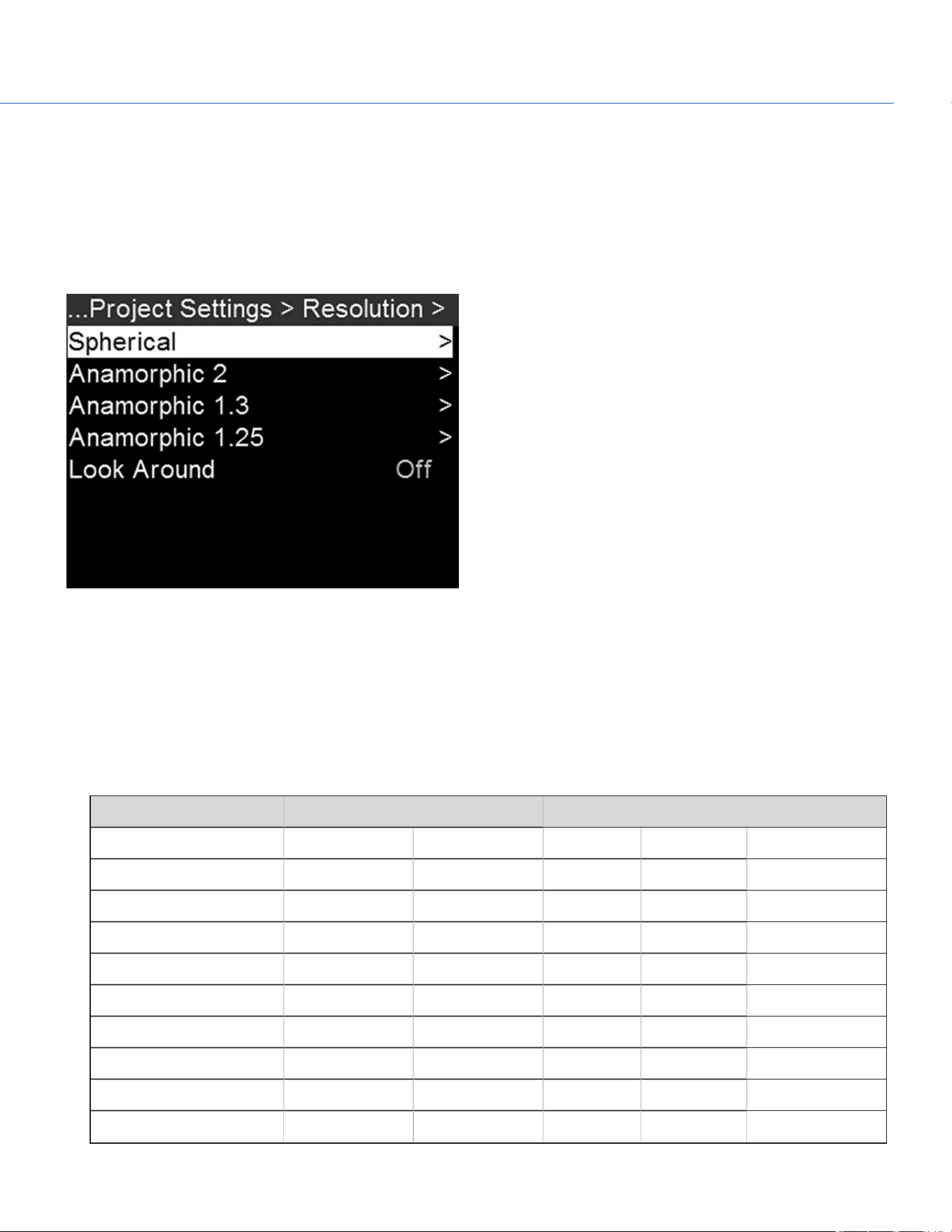
RESOLUTION
Figure: Resolution Menu
To select a resolution, go to Menu > Project Settings > Resolution.
Select a Spherical (non-anamorphic) or Anamorphic option, and then select the resolution and aspect ratio. The default
format for Panavision Millennium DXL2 is 8K 2:1.
The table below describes the formats that are available for Panavision Millennium DXL2.
The table below omits rows for the anamorphic formats, since the pixel dimensions for each anamorphic format and the
corresponding non-anamorphic format are the same. For more information, go to "Anamorphic" on page44.
RESOLUTION DIMENSIONS (PIXELS) DIMENSIONS (MM)
WIDTH HEIGHT WIDTH HEIGHT DIAGONAL
8K Full Format 8192 4320 40.96 21.60 46.31
8K 2:1 8192 4096 40.96 20.48 45.79
8K 2.4:1 (WS) 8192 3456 40.96 17.28 44.46
8K 16:9 (HD) 7680 4320 38.40 21.60 44.06
7.5K Full Format 7680 4080 38.40 20.40 43.48
7.5K 2:1 7680 3840 38.40 19.20 42.93
7.5K 2.4:1 (WS) 7680 3240 38.40 16.20 41.68
7.5K 16:9 (HD) 7296 4104 36.48 20.52 41.86
7K Full Format 7168 3780 35.84 18.90 40.52

RESOLUTION DIMENSIONS (PIXELS) DIMENSIONS (MM)
WIDTH HEIGHT WIDTH HEIGHT DIAGONAL
7K 2:1 7168 3584 35.84 17.92 40.07
7K 2.4:1 (WS) 7168 3024 35.84 15.12 38.90
7K 16:9 (HD) 6720 3780 33.60 18.90 38.55
6.5K Full Format 6656 3536 33.28 17.68 37.68
6.5K 2:1 6656 3328 33.28 16.64 37.21
6.5K 2.4:1 (WS) 6656 2808 33.28 14.04 36.12
6.5K 16:9 (HD) 6144 3456 30.72 17.28 35.25
6K Full Format 6144 3240 30.72 16.20 34.73
6K 2:1 6144 3072 30.72 15.36 34.35
6K 2.4:1 (WS) 6144 2592 30.72 12.96 33.34
6K 16:9 (HD) 5760 3240 28.80 16.20 33.04
5K Full Format 5120 2700 25.60 13.50 28.94
5K 2:1 5120 2560 25.60 12.80 28.62
5K 2.4:1 (WS) 5120 2160 25.60 10.80 27.78
5K 16:9 (HD) 4800 2700 24.00 13.50 27.54
4K Full Format 4096 2160 20.48 10.80 23.15
4K 2:1 4096 2048 20.48 10.24 22.90
4K 2.4:1 (WS) 4096 1728 20.48 8.64 22.23
4K 16:9 (HD) 3840 2160 19.20 10.80 22.03
3K Full Format 3072 1620 15.36 8.10 17.36
3K 2.4:1 (WS) 3072 1296 15.36 6.48 16.67
3K 16:9 (HD) 2880 1620 14.40 8.10 16.52
2K Full Format 2048 1080 10.24 5.40 11.58
2K 2.4:1 (WS) 2048 864 10.24 4.32 11.11
COP YRIGHT © 2020 PA N A VISION IN TERN ATION AL, L.P . FW : V-1.0.0| 43
PANAVISION MILLENNIUM DXL2

ANAMORPHIC
Figure: Anamorphic
The Panavision Millennium DXL2 supports the anamorphic options listed in the following sections.
ANAMORPHIC 2
8K 6.5
7.5K 6:5
7K 6.5
6.5K 6:5
6K 6.5
5K 6.5
4K 6.5
NOTE: Using a 6:5 aspect ratio at 2x anamorphic gives you a 2.4:1 aspect ratio.
COP YRIGHT © 2020 PA N A VISION IN TERN ATION AL, L.P . FW : V-1.0.0| 44
PANAVISION MILLENNIUM DXL2

ANAMORPHIC 1.3
8K Full Format
8K 16:9 (HD)
7.5K Full Format
7.5K 16:9 (HD)
7K Full Format
7K 16:9 (HD)
6.5K Full Format
6.5K 16:9 (HD)
6K Full Format
6K 16:9 (HD)
5K Full Format
5K 16:9 (HD)
4K Full Format
4K 16:9 (HD)
3K Full Format
2K Full Format
ANAMORPHIC 1.25
8K Full Format
6K Full Format
LOOK AROUND
When Look Around is enabled, the Frame Guide and recording area are scaled down on the display so that you can see what
images will enter the recording area.
To assign a Shading overlay to the Look Around area (the area outside of the recording area), go to "Frame Lines" on
page60.
Look Around limits the available frame rates. At high resolutions, the recording area on the display shows the full sensor area
or full sensor height, so there is no extra room for Look Around.
REDCODE
Select the target REDCODE compression ratio for your project.
If the camera is able to achieve the target compression ratio, the compression ratio displays in white. If the camera is unable
to achieve the target compression ratio, the compression ratio displays in yellow, and the camera uses the next possible
compression ratio.
The current compression ratio is automatically recalculated when changes are made to the project resolution, aspect ratio,
anamorphic setting, frame rate, media, or the target REDCODE compression ratio.
The RECODE compression affects the overall quality of the footage. A lower compression (for example: 2:1) increases the
quality of the footage, while a higher compression (for example: 22:1) lowers the quality.
For more information, go to "R3D File Format and REDCODE" on page7.
COP YRIGHT © 2020 PA N A VISION IN TERN ATION AL, L.P . FW : V-1.0.0| 45
PANAVISION MILLENNIUM DXL2

APPLE PRORES INFORMATION
By default, the camera records all videos and stills in the REDCODE RAW file format (records R3D files). You also have the
option to record Apple ProRes files. This section provides general information about recording Apple ProRes files with the
camera:
NOTE: If Look Around is enabled, the Look Around area is recorded in the Apple ProRes file.
Selecting a Recording Frame Rate that is not supported by Apple ProRes has the following effects:
4K Apple ProRes over 60 FPS: Apple ProRes is disabled.
4K Apple ProRes + R3D over 29.97 FPS: Apple ProRes is disabled.
The camera cannot record Apple ProRes when Pre-Record is enabled.
Recording to R3D + Apple ProRes is not supported when the format is 4K FF.
QuickTime files have the same metadata that is in the REDCODE RAW files. The metadata is per clip, and not per frame.
At this time, there is no tool for extracting that metadata from the QuickTime files.
You can select any resolution. When recording Apple ProRes, the camera scales that format to the Resolution (2K or 4K)
selected in the Codec menu. The field of view is maintained in the QuickTime file; the image is not cropped.
If recording 4K Apple ProRes and the Resolution is less than 4K, the image is scaled to 2K.
For more information about Apple ProRes, including the data rates for each codec, see the Apple Support site at
https://support.apple.com/en-us/HT202410.
To record Apple ProRes files, go to "Select Record File Format" on page50
COP YRIGHT © 2020 PA N A VISION IN TERN ATION AL, L.P . FW : V-1.0.0| 46
PANAVISION MILLENNIUM DXL2
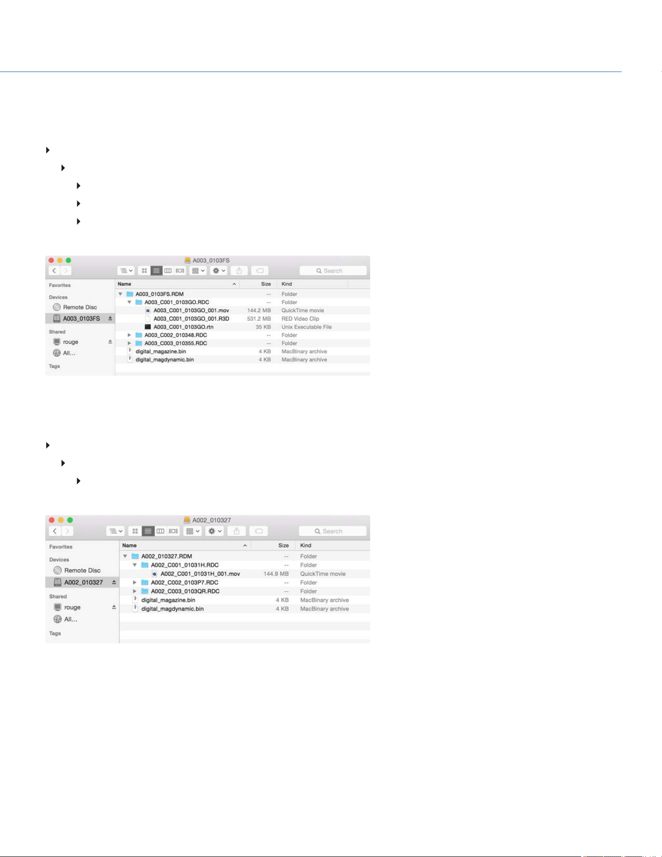
FILE STRUCTURE OF RECORDED APPLE PRORES FILES
When recording R3D + Apple ProRes, this is the file structure of the recorded files on the SSD (when the SSD is formatted as
FAT32):
.RDM Folder
.RDC Folder
.mov
.R3D
.rtn (RED Thumbnail file)
NOTE: The camera creates mulitple .mov files, similar to how the camera creates multiple R3D files.
Figure: File Structure: R3D + Apple ProRes
When recording Apple ProRes only, this is the file structure of the recorded files on the SSD (when the SSD is formatted as
FAT32):
.RDM Folder
.RDC Folder
.mov
NOTE: The camera creates mulitple .mov files, similar to how the camera creates multiple R3D files.
Figure: File Structure: Apple ProRes
COP YRIGHT © 2020 PA N A VISION IN TERN ATION AL, L.P . FW : V-1.0.0| 47
PANAVISION MILLENNIUM DXL2
AVID DNXHD AND AVID DNXHR INFORMATION
By default, the camera records all videos and stills in the REDCODE RAW file format (records R3D files). You also have the
option to record to Avid DNxHD and Avid DNxHR (records .mxf files). This section provides general information about
recording Avid DNxHD/HR with the camera:
NOTE: If Look Around is enabled, the Look Around area is recorded in the Avid DNxHD/HR file.
NOTE: Enabling Look Around affects the aspect ratio of the scaled file, regardless of the recorded area.
Selecting a Recording Frame Rate that is not supported by Avid DNxHD/HR causes the codec file to be sub-sampled to
half of the selected Recording Frame Rate.
The camera cannot record Avid DNxHD/HR when Pre-Record is enabled.
The .mxf files have the same metadata that is in the REDCODE RAW files. The metadata is per clip, and not per frame. At
this time, there is no tool for extracting that metadata from the .mxf files.
You can select any resolution. When recording Avid DNxHD/HR, the camera scales that format to the Resolution (2K or
4K) selected in the Codec menu. The field of view is maintained in Avid DNxHD/HR; the image is not cropped.
For more information about Avid DNxHD/HR, see the Avid website at www.avid.com/en/products/avid-dnxhr-and-dnxhd.
To record Avid DNxHD/HR, go to "Select Record File Format" on page50
AVID DNXHD AND AVID DNXHR DESCRIPTION
The table below describes each Avid DNxHD/HR codec.
NAME CODEC ID BITS COLOR
DNxHR HQX 1271 12 bit YCbCr 4:2:2
DNxHR HQ 1272 8 bit YCbCr 4:2:2
DNxHR SQ 1273 8 bit YCbCr 4:2:2
DNxHR LB 1274 8 bit YCbCr 4:2:2
DNxHR 444 1270 12 bit RGB 4:4:4
DNxHD 444 1256 10 bit RGB 4:4:4
DNxHD HQX 1235 10 bit YCbCr 4:2:2
DNxHD HQ 1238 8 bit YCbCr 4:2:2
DNxHD SQ 1237 8 bit YCbCr 4:2:2
DNxHD LB 1253 8 bit YCbCr 4:2:2
COP YRIGHT © 2020 PA N A VISION IN TERN ATION AL, L.P . FW : V-1.0.0| 48
PANAVISION MILLENNIUM DXL2
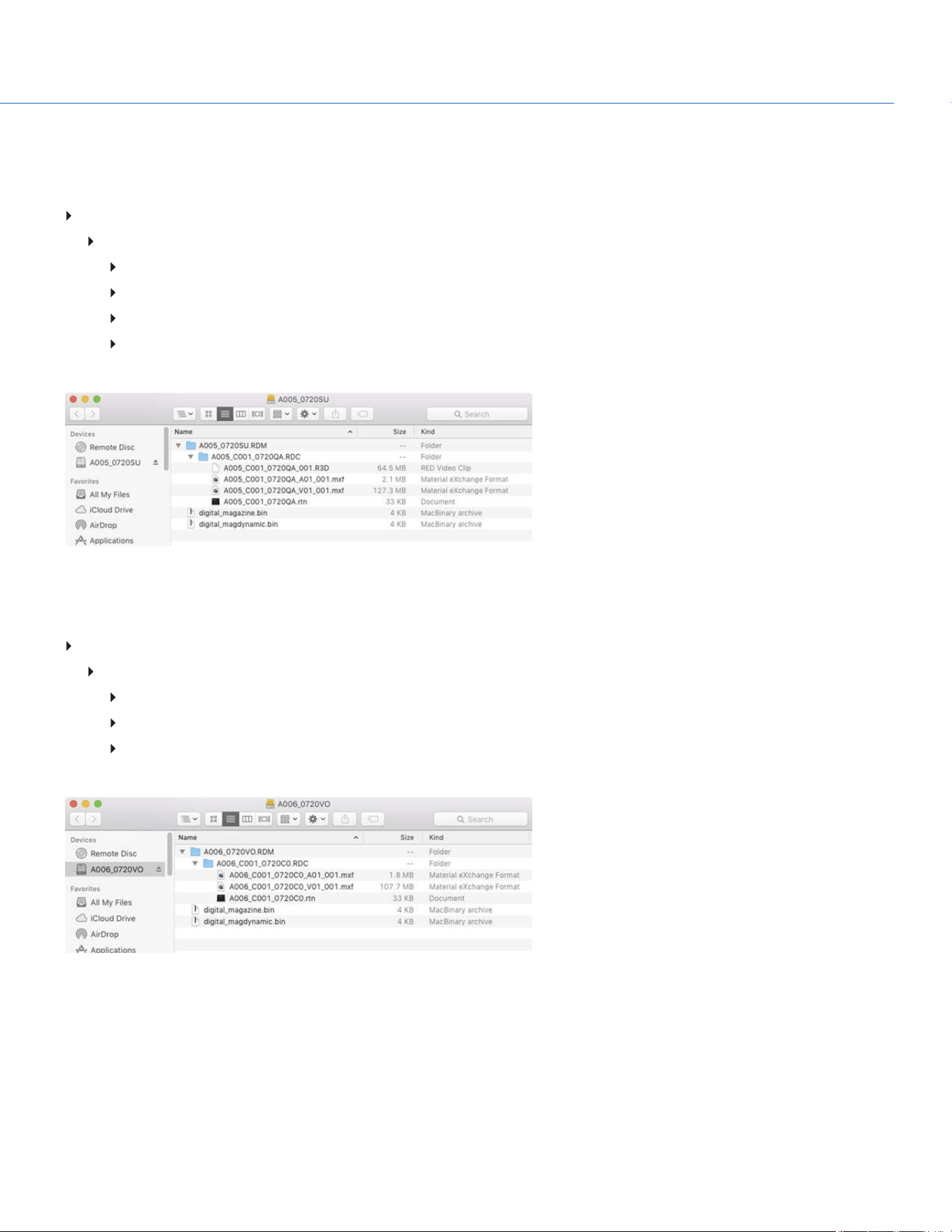
FILE STRUCTURE OF RECORDED AVID CODEC FILES
When recording R3D + Avid DNxHD/HR, this is the file structure of the recorded files on the SSD (when the SSD is formatted
as FAT32):
.RDM Folder
.RDC Folder
.R3D
.mxf (audio file, marked with an “A”)
.mxf (video file, marked with a “V”)
.rtn (RED Thumbnail file)
NOTE: The camera creates mulitple .mxf files, similar to how the camera creates multiple R3D files.
Figure: File Structure: R3D + DNxHD/HR
When recording Avid DNxHD/HR only, this is the file structure of the recorded files on the SSD (when the SSD is formatted as
FAT32):
.RDM Folder
.RDC Folder
.mxf (audio file, marked with an “A”)
.mxf (video file, marked with a “V”)
.rtn (RED Thumbnail file)
NOTE: The camera creates mulitple .mxf files, similar to how the camera creates multiple R3D files.
Figure: File Structure: R3D + DNxHD/HR
COP YRIGHT © 2020 PA N A VISION IN TERN ATION AL, L.P . FW : V-1.0.0| 49
PANAVISION MILLENNIUM DXL2

SELECT RECORD FILE FORMAT
NOTE: For more information on which codecs your camera offers, go to "Technical Specifications" on page132.
To select what file formats to record to, follow the instructions below.
1. Go to Menu > Project Settings > Codec.
Figure: Codec Menu
2. Select the file format(s) you want to record to:
R3D
R3D + Apple ProRes
R3D + Avid DNxHD/HR
Apple ProRes
Avid DNxHD/HR
The selected file format displays in the Lower Status Row.
3. R3D: Select a target REDCODE compression ratio. For more information, go to "REDCODE" on page45.
4. To set up Apple ProRes:
A. In the Codec menu, select the Apple ProRes menu.
B. Select the Resolution.
C. Select the Video Codec.
The recording dimensions display at the bottom of the Apple ProRes menu.
5. To set up Avid DNxHD/HR:
A. In the Codec menu, select the Avid DNxHD/HR menu.
B. Select the Resolution.
C. Select the Video Codec.
The recording dimensions display at the bottom of the Apple ProRes menu.
6. Apple ProRes or Avid DNxHD/HR: Select a codec from the Record Video Codec drop-down menu.
COP YRIGHT © 2020 PA N A VISION IN TERN ATION AL, L.P . FW : V-1.0.0| 50
PANAVISION MILLENNIUM DXL2

FRAME RATE
RECORDING FRAME RATE
The recording frame rate is the number of frames per second (fps) that are recorded. The recording frame rate is different
from the project time base, which is the rate at which the footage will be played back.
The default recording frame rate is 23.98 fps. If you change the project time base, the recording frame rate automatically
changes its value to match the project time base.
The maximum frame rate for each format is determined by several factors, including project time base, REDCODE, and Look
Around.
To set the recording frame rate, follow the instructions below:
1. Select FPS from the Home Page.
The Recording Frame Rate menu opens.
2. Select an option from the list, or select Custom to select a custom recording frame rate.
Figure: Recording Frame Rate
COP YRIGHT © 2020 PA N A VISION IN TERN ATION AL, L.P . FW : V-1.0.0| 51
PANAVISION MILLENNIUM DXL2
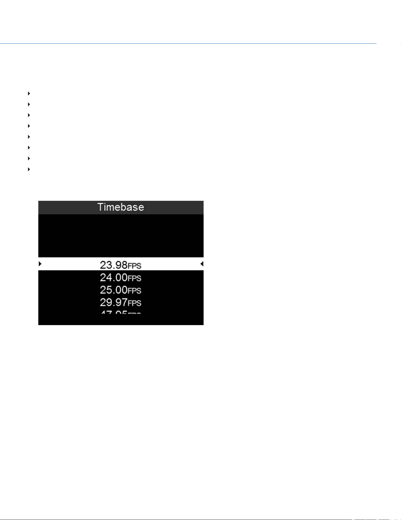
PROJECT TIME BASE
The project time base is the rate at which the footage will be played back.
The following project time bases are available:
23.98 fps (Default)
24.00 fps
25.00 fps
29.97 fps
47.95 fps
48.00 fps
50.00 fps
59.94 fps
To select a project time base, follow the instructions below:
1. Go to Menu > Project Settings > Timebase.
Figure: Timebase
VARISPEED
When a recording frame rate other than the current project time base is selected, the fps text turns yellow.
COP YRIGHT © 2020 PA N A VISION IN TERN ATION AL, L.P . FW : V-1.0.0| 52
PANAVISION MILLENNIUM DXL2

SLATE
Use the Slate menu to add metadata to clips. After configuring the following fields, the information populates in the Media
menu when formatting media:
Camera ID
Camera Position
To set the Slate information, follow the instructions below:
1. Go to Menu > Project Settings > Slate.
2. Set up the following:
Camera ID
Camera Position
Camera Color:Changes the color of the Clip Information slot on the user interface Home Page. For more information,
go to "Home Page" on page29.
Production
Director
DoP
Unit
COP YRIGHT © 2020 PA N A VISION IN TERN ATION AL, L.P . FW : V-1.0.0| 53
PANAVISION MILLENNIUM DXL2
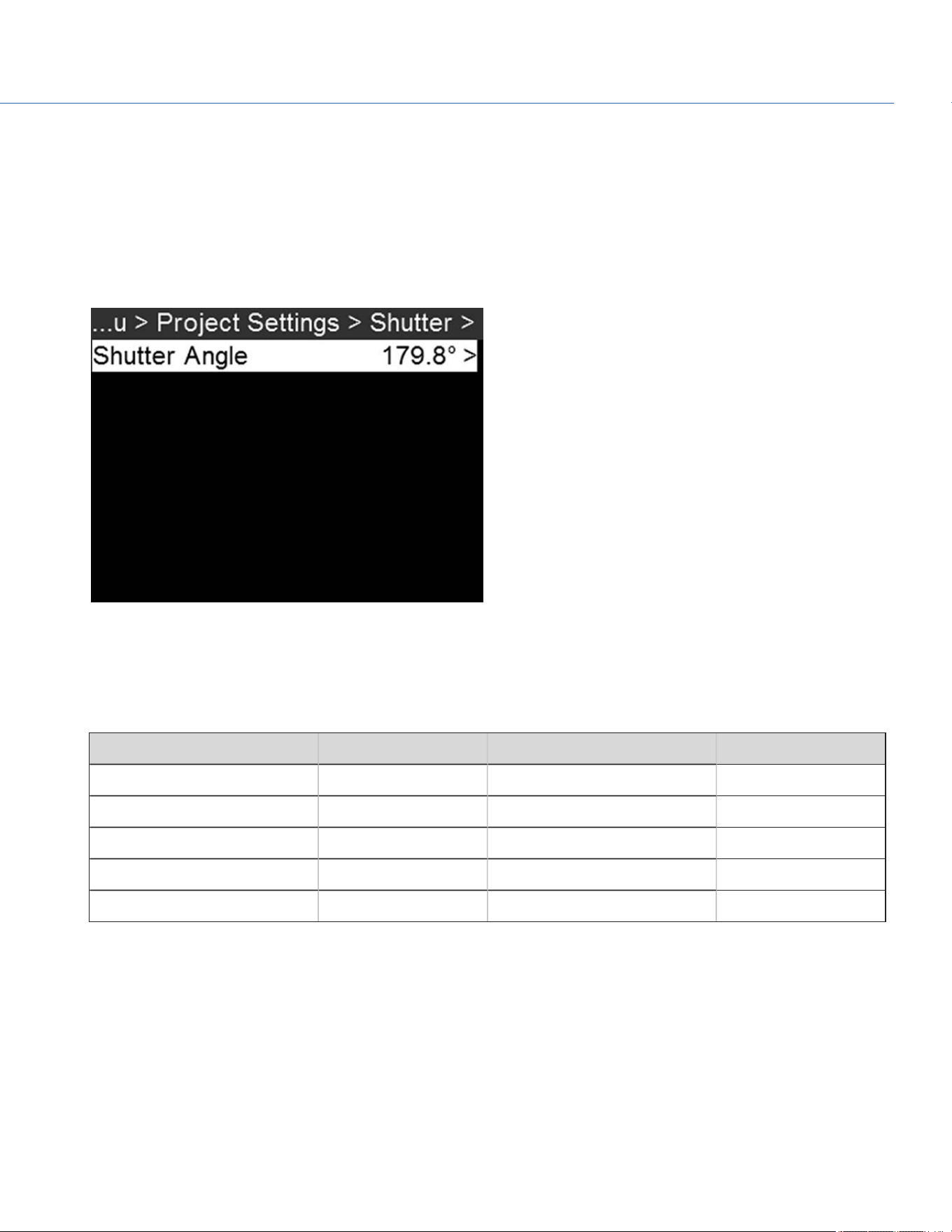
EXPOSURE/SHUTTER
Select the exposure (shutter speed / shutter angle) of each frame. You can change exposure while recording.
SHUTTER ANGLE
To set the shutter angle, follow the instructions below:
1. Go to Menu > Project Settings > Shutter > Shutter Angle.
2. Select an option from the list, or select Custom to select a custom shutter angle.
Figure: Shutter
EXPOSURE CONVERSIONS
The table below lists common shutter speed and shutter angle equivalents. The calculations in the table use a recording
frame rate of 24 fps.
SHUTTER SPEED (1/XX SEC) SHUTTER ANGLE (°) SHUTTER SPEED (1/XX SEC) SHUTTER ANGLE (°)
1/32 270 1/120 72
1/48 180 1/192 45
1/50 172.8 1/384 22.5
1/60 144 1/696 12.4
1/96 90 1/1000 8.6
CONVERT SHUTTER SPEED TO SHUTTER ANGLE
Shutter Angle = (Shutter Speed x Frame Rate x 360)
Example: (1/48 x 24 x 360) = 180
CONVERT SHUTTER ANGLE TO SHUTTER SPEED
Shutter Speed = 1/(Frame Rate x 360/Angle)
Example: 1/(24 x 360/180) = 1/48
COP YRIGHT © 2020 PA N A VISION IN TERN ATION AL, L.P . FW : V-1.0.0| 54
PANAVISION MILLENNIUM DXL2

TIMECODE
To set up timecode, go to Menu > Project Settings > Timecode.
For more information about timecode, go to "Timecode, Genlock, Multi-Camera Setup" on page114.
TIMECODE
SOURCE
MODE DESCRIPTION
RTC Use Real Time Clock
(RTC)
Uses the internal Real Time Clock as the timecode counter source. You can set
the hours, minutes, and seconds in the numerical boxes on the screen.
External Varies by device Uses the timecode from an external device connected to the TIMECODE port on
the camera.
ACN Use ACN Enables the camera to directly interact with the wireless Ambient
communication and synchronization network (ACN™). This delivers line-accurate
syncing of all production cameras while syncing picture with sound. The signal
also includes metadata. This can be accessed via the TIMECODE port (5-pin
LEMO) on the Communication Module. For more information, go to "TIMECODE"
on page146.
LTC OUT
Enable LTC Out to output the linear timecode signal generated by the camera through the TIMECODE port on the camera.
NOTE: If jamming camera timecode to a timecode device, ensure that LTC Out is disabled.
To enable LTC Out, follow the instructions below:
1. Go to Menu > Project Settings > Timecode.
2. Select LTC Out to toggle this feature on/off.
WIRELESS CHANNEL
If the Timecode Source is set to ACN, you can sync wireless timecode devices with the camera.
To select a wireless channel, follow the instructions below:
1. Menu > Project Settings > Timecode.
2. Set Wireless Channel to the same wireless channel as the device. The camera supports channels 11 to 18.
COP YRIGHT © 2020 PA N A VISION IN TERN ATION AL, L.P . FW : V-1.0.0| 55
PANAVISION MILLENNIUM DXL2

PRE-RECORD
To set up Pre-Record, go to Menu > Project Settings > Pre-Record.
When enabled, the Pre-Record setting continuously captures a cache of footage before recording starts. Select to have 4 to
30 seconds (incremented at two second intervals) of pre-record time added to the actual footage. When Pre-Record is
enabled, you will not miss the start of a shot by being a little slow on the trigger.
Duration: Select the pre-record time.
Always trigger: When selected, Pre-Record always starts when recording starts:
Press PWR/REC to activate Pre-Record.
Press PWR/REC a second time to start recording.
Press PWR/REC a third time to stop recording.
Trigger Pre-Record: When selected, the Pre-Record menu closes and Pre-Record mode starts.
NOTE: Always perform a Full Format before using Pre-Record. A Full Format restores the SSD back to factory out-of-box
settings, and optimizes the SSD for Pre-Record.
NOTE: Pre-Record puts your SSD in a state of constant record. As with any SSD technology, continuously writing data over an
extended period of time will impact the lifespan of the media.
COP YRIGHT © 2020 PA N A VISION IN TERN ATION AL, L.P . FW : V-1.0.0| 56
PANAVISION MILLENNIUM DXL2

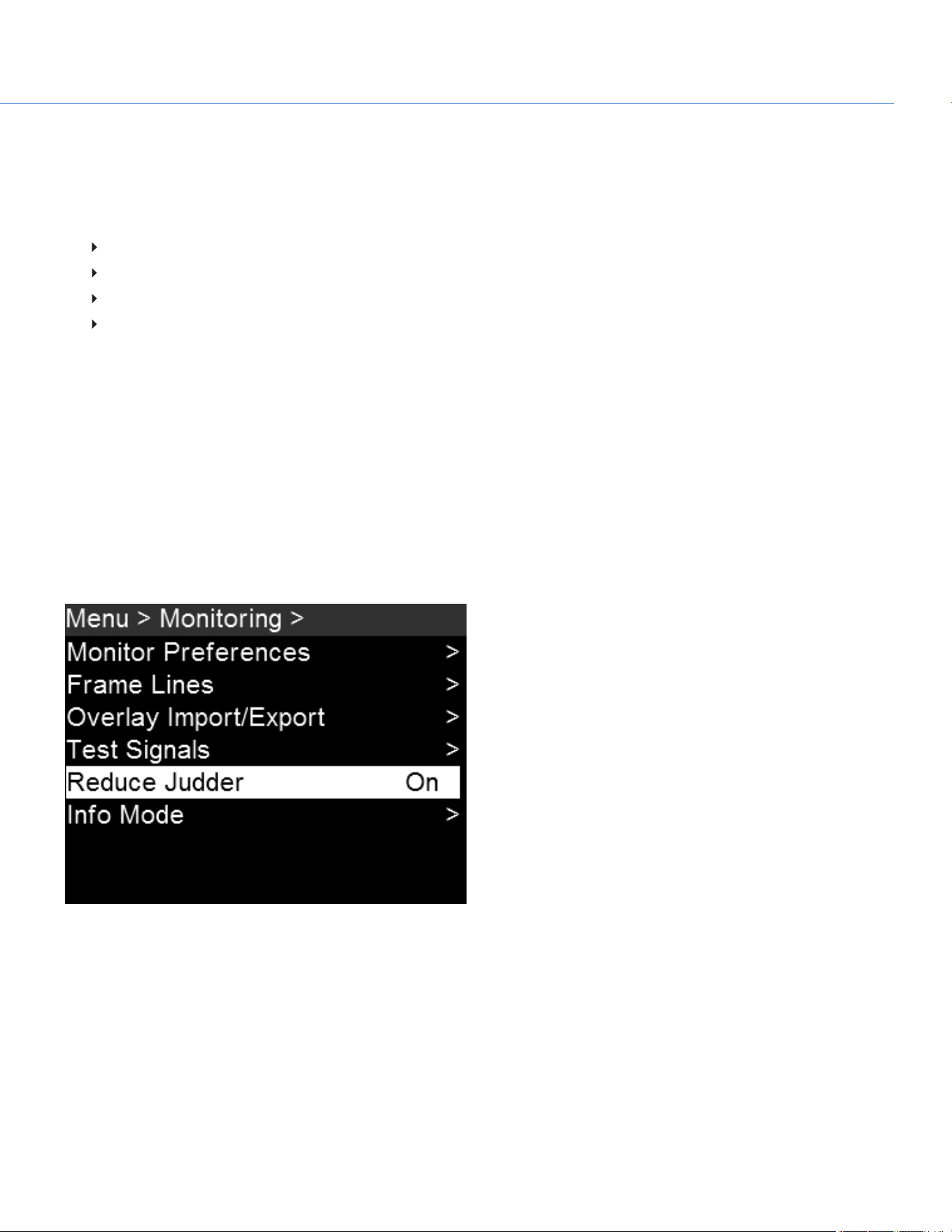
MONITORING
Figure: Monitoring Menu
MONITOR PREFERENCES
To set up monitor preferences, go to Menu > Monitoring > Monitor Preferences and select the monitor whose preferences
you want to change. You can set up preferences for each of the following monitors:
SDI 1
SDI 2
SDI 3
SDI 4
SDI 5
UHD
Assistant Port
Top Port
Operator Port
To see what monitor preferences are available, go to "Monitor " on the next page.
COP YRIGHT © 2020 PA N A VISION IN TERN ATION AL, L.P . FW : V-1.0.0| 57
PANAVISION MILLENNIUM DXL2
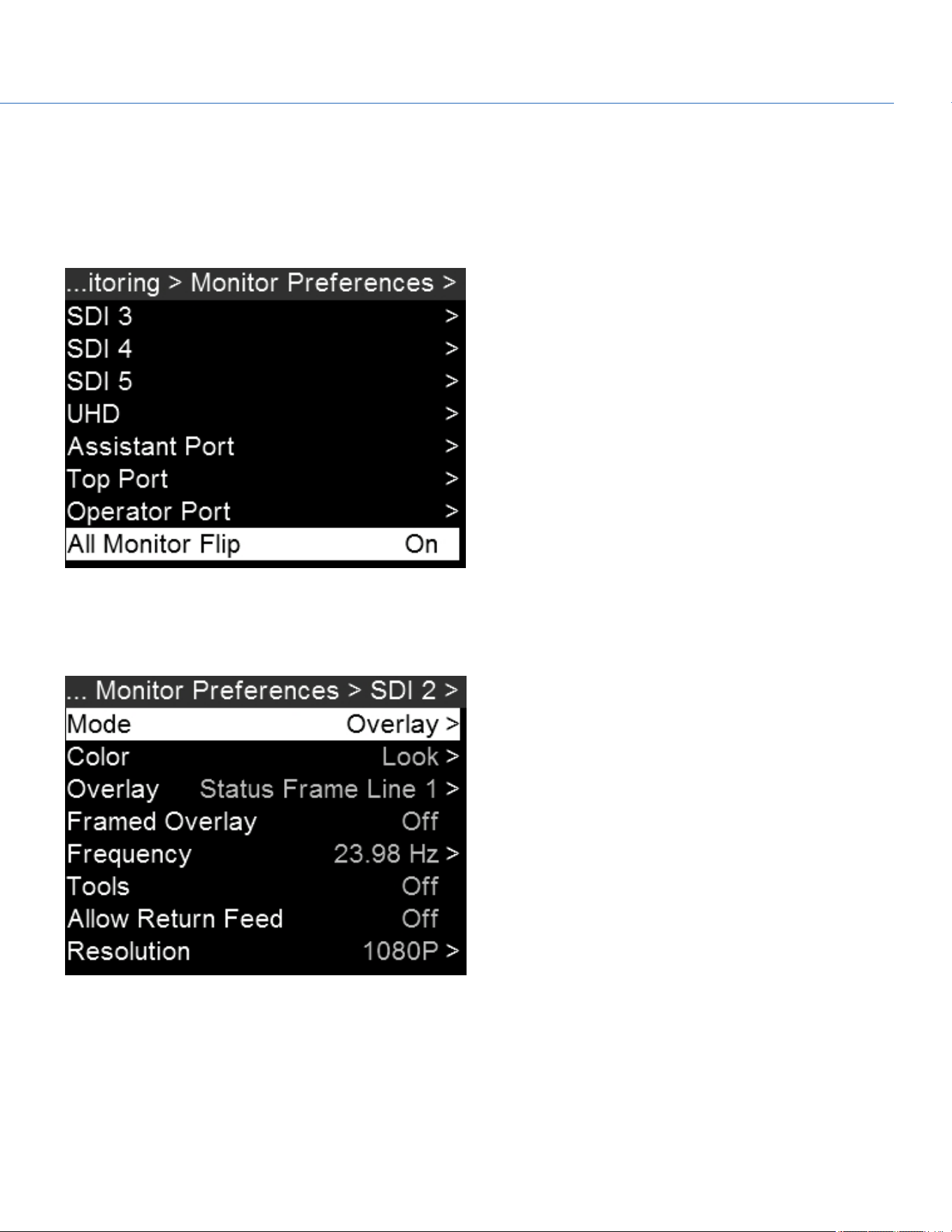
ALL MONITOR FLIP
To flip the image upside-down in all connected monitors (for example, when shooting with a Steadicam in low mode), follow
the instructions below:
1. Go to Menu > Monitoring > Monitor Preferences.
2. Scroll down to All Monitor Flip and toggle On/Off.
Figure: All Monitor Flip
MONITOR
NOTE: While some changes take effect immediately, others take effect when you close the menu.
Figure: Monitor Preferences
COP YRIGHT © 2020 PA N A VISION IN TERN ATION AL, L.P . FW : V-1.0.0| 58
PANAVISION MILLENNIUM DXL2

MONITOR MODE
Select an option for the Mode setting, which determines the elements displayed on the monitor:
Clean: Only the video displays.
Overlay: The overlay displays.
Mirror: The monitor mirrors another screen at the same resolution. You cannot mirror a screen that is set to Clean. The
Mirror option is available based on the settings of the other attached monitors, and includes the name of the monitor that
can be mirrored.
COLOR
Select an option for the Color setting, which determines the color profile that will display on the monitor:
Look: The chosen LUT and CDLsettings will display.
LOG: The LOGfeed, without any LUTor CDLsettings, will display.
OVERLAY
Select which overlay shows on top of the video. The camera comes with preset overlays. To see what overlays are available,
go to "Overlay Import/Export" on page62.
RESOLUTION
Select the output resolution for monitors. You cannot select a resolution for view finders (VFs), since the resolution is
determined automatically. For more information about available HD-SDI and HDMI resolutions, go to 3G-SDI (HD-SDI) Out
and HDMI Out.
FREQUENCY
Determines the monitor frequency. Available frequencies depend on the selected monitor.
For HD-SDI monitors, the frequency depends on the project time base. For more information, go to 3G-SDI (HD-SDI) Out and
HDMI Out.
HD-SDI Auto: Sets the frequency equal to the Project Time Base, except when the Project Time Base is 47.95/48 fps. When
the Project Time Base is 47.95/48 fps, the frequency is half that rate (23.98/24 Hz).
TOOLS
Enables the false color modes on the monitor. For more information, go to Tools.
FRAMED OVERLAY
The video display is scaled down on the monitor so that the overlay items fit outside of the video area rather than over it. This
setting only affects the monitor, and does not affect captured footage.
COP YRIGHT © 2020 PA N A VISION IN TERN ATION AL, L.P . FW : V-1.0.0| 59
PANAVISION MILLENNIUM DXL2
ALLOW RETURN FEED
The camera allows you to input a 1080p 3G video feed into the camera, and then display that video on another monitor. To
feed video into the camera and display it on a monitor, follow the instructions below:
1. Input an external feed:
A. Connect the device with the feed to the RETURNconnector on the camera. For more information, go to "RETURN" on
page143.
2. Enable the monitor to support the external feed:
A. Go to Menu > Monitoring > Monitor Preferences.
B. Select the monitor you want to see the live feed on.
C. Enable Allow Return Feed.
3. Map a key that will toggle between the actual feed and the external feed:
A. Go to Menu > User Presets > Key Mapping.
B. Select the key you want to map.
C. Select Return Feed.
4. When you are ready to display the external feed on the monitors, press the key mapped to Return Feed.
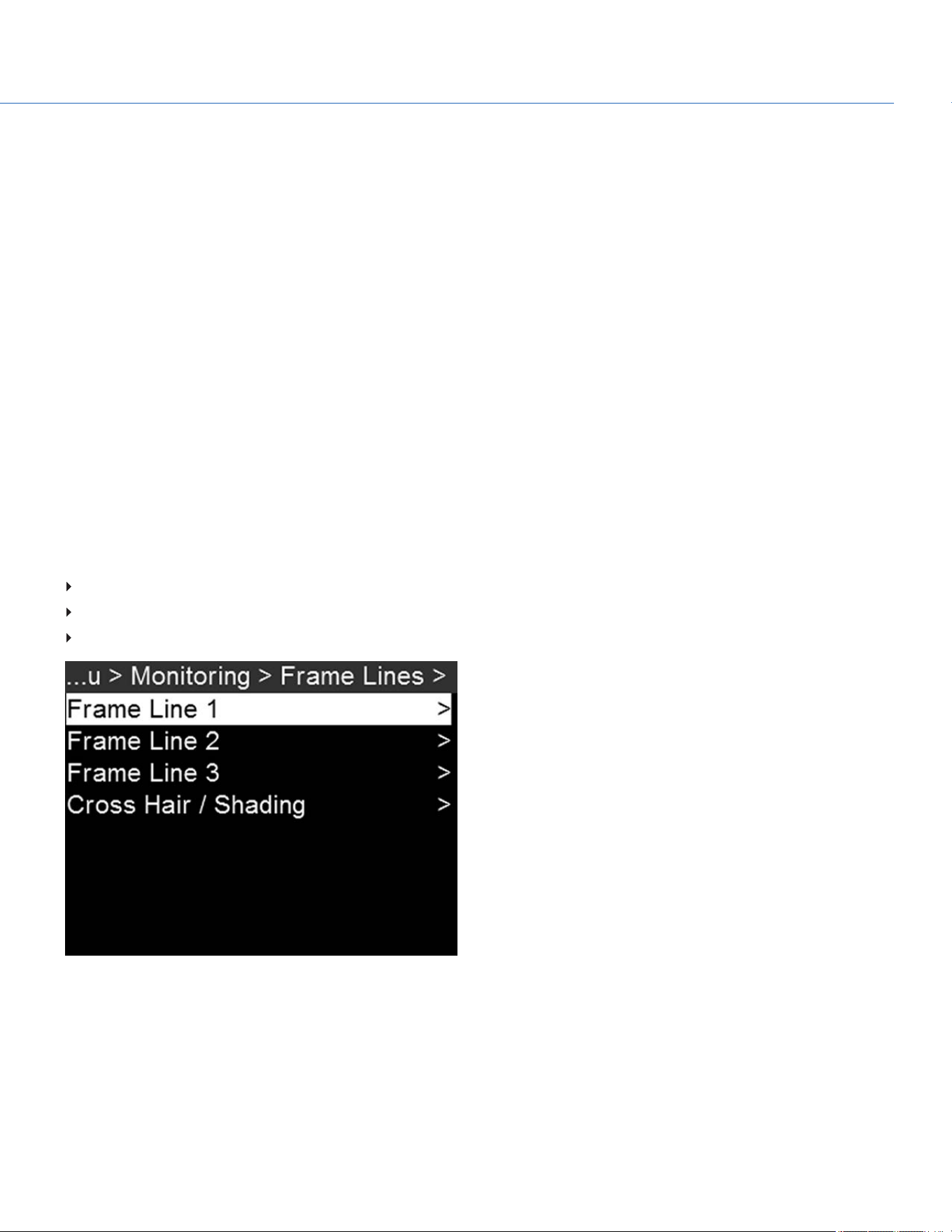
FRAME LINES
To set up the frame lines, go to Menu > Monitoring > Frame Lines. The camera offers up to three (3) frame lines:
Frame Line 1
Frame Line 2
Frame Line 3
Figure: Frame Lines
COP YRIGHT © 2020 PA N A VISION IN TERN ATION AL, L.P . FW : V-1.0.0| 60
PANAVISION MILLENNIUM DXL2

MODE
Off: Disable all guides.
Full: Guide has the same aspect ratio as the record format.
4:3, 16:9, 1.85:1, 1.9:1, 2.4:1: Guide has the selected aspect ratio.
User: When you select User, the Mode menu closes and the Frame Line menu opens. Select User Aspect Ratio and select
the aspect ratio you want.
Absolute: Guide is defined by absolute pixel dimensions rather than aspect ratio and scale. When you select Absolute, the
Mode menu closes and the Frame Line menu opens. Select and set up the following:
Absolute Offset X
Absolute Offset Y
Absolute Width
Absolute Height
SCALE
Percentage to scale guide from its maximum possible size. Available range is 0 to 100%.
OFFSET X/Y
Percentage to offset guide from its default centered position. Available range is –100 to 100%.
100%: Right-aligned (for X offset) and bottom-aligned (for Y offset).
-100%: Left-aligned (for X offset) and top-aligned (for Y offset).
APPEARANCE
Line Style: Select one of the following line styles: Solid, Dashed, or Bracket.
Color: Select the color that has the highest contrast to the scene. The default is White.
Opacity: Set the guide opacity. Available options are 25%, 50%, 75% and 100%.
CROSS HAIR / SHADING
Enable/Disable and select the location (Relative To), color, and opacity of the following elements:
Center: The center crosshair.
Shading: The shaded region outside of the area of interest.
COP YRIGHT © 2020 PA N A VISION IN TERN ATION AL, L.P . FW : V-1.0.0| 61
PANAVISION MILLENNIUM DXL2
OVERLAY IMPORT/EXPORT
Overlays can be stored on the camera or transferred to SSD to be shared with other cameras. To apply an overlay to a
monitor, go to "Monitor Preferences" on page57.
In Camera: Overlays saved internally on the camera.
On Media: Overlays saved to an SSD.
IMPORT FROM SSD TO CAMERA
To import overlays from an SSD to the camera, follow the instructions below:
1. Go to Menu > Monitoring > Overlay Import/Export.
2. Select On Media: \overlays.
3. Select one of the following:
Import
Import All
EXPORT FROM SSD TO CAMERA
To export overlays from the camera to an SSD, follow the instructions below:
1. Go to Menu > Monitoring > Overlay Import/Export.
2. Select In Camera.
3. Select one of the following:
Delete
Export
Export All
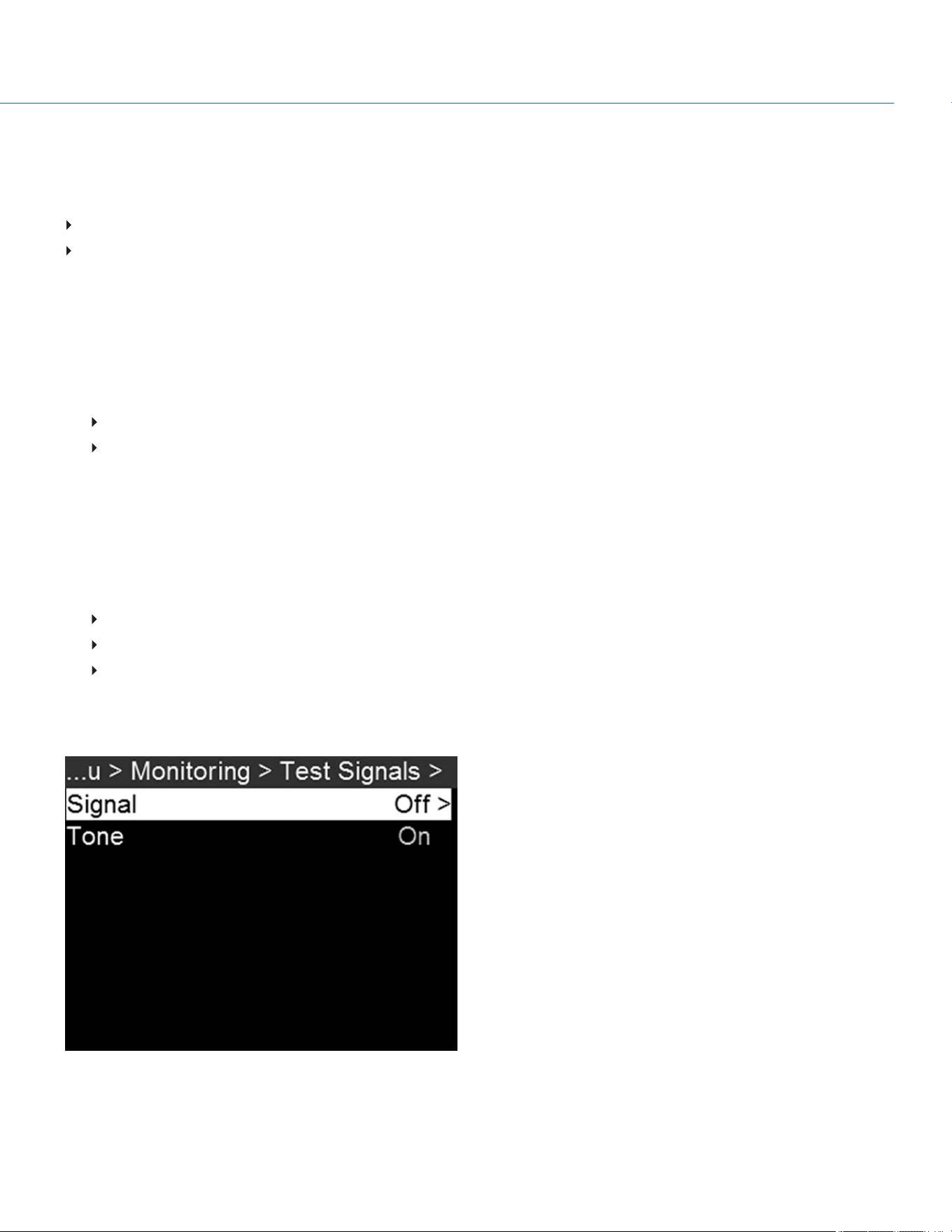
TEST SIGNAL
NOTE: Test signals are not recordable; they are provided to help align external HD-SDI monitors.
Figure: Test Signals
COP YRIGHT © 2020 PA N A VISION IN TERN ATION AL, L.P . FW : V-1.0.0| 62
PANAVISION MILLENNIUM DXL2
SIGNAL
To apply a video test pattern, follow the instructions below:
1. Go to Menu > Monitoring > Test Signals > Signal.
2. Select one of the following options:
Off
Chip Chart
SMPTE Bars
Luma
AUDIO TONE
To apply an audio tone, follow the instructions below:
1. Go to Menu > Monitoring > Test Signals.
2. Toggle Tone On/Off.
REDUCE JUDDER
To reduce apparent judder when viewing the camera feed on an external monitor, follow the instructions below:
1. Go to Menu > Monitoring.
2. Scroll down to Reduce Judder and toggle On/Off.
NOTE:Reduce Judder can only be turned on when capturing in RAWformat; it will not work if proxy mode is enabled.
Figure: Reduce Judder
COP YRIGHT © 2020 PA N A VISION IN TERN ATION AL, L.P . FW : V-1.0.0| 63
PANAVISION MILLENNIUM DXL2
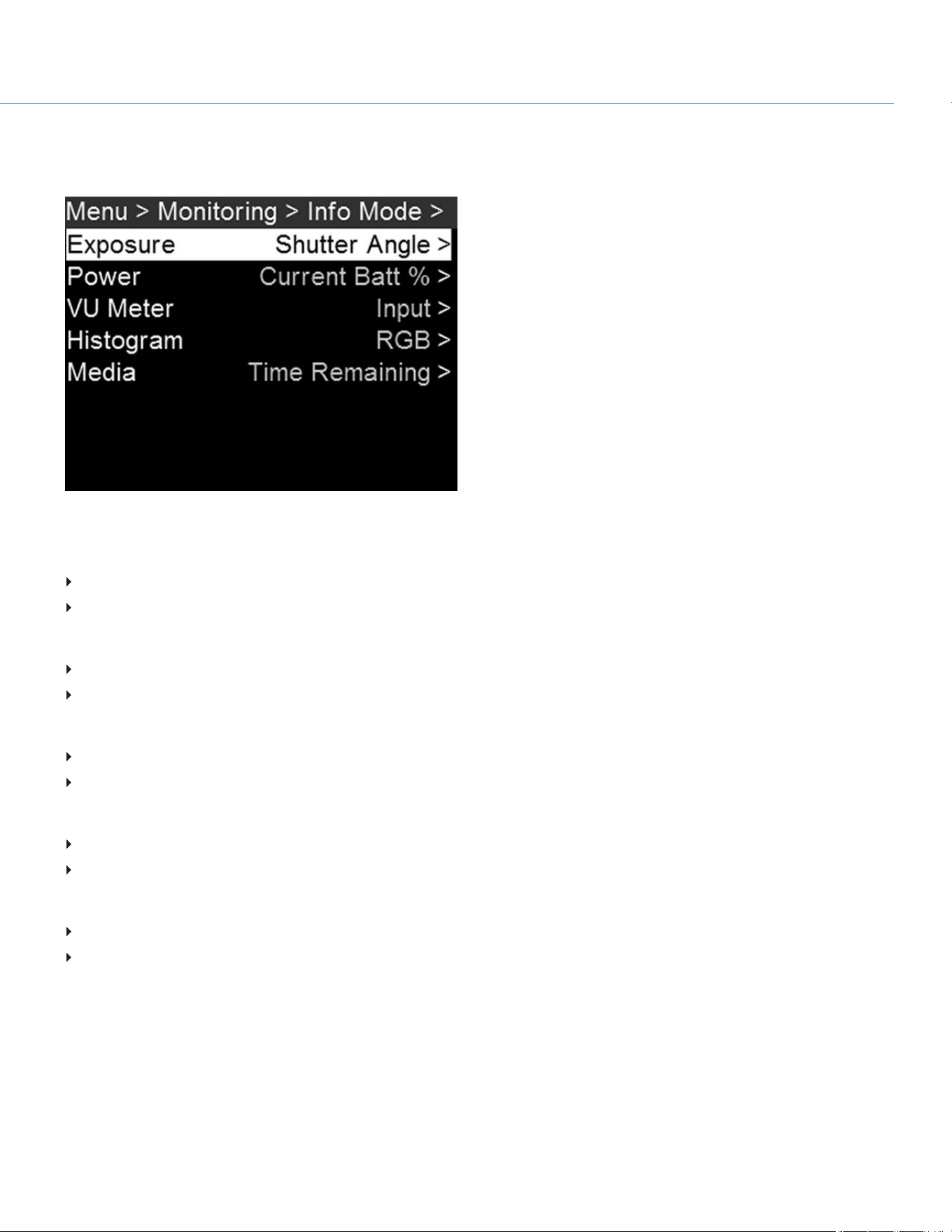
INFO MODE
To set up how certain information displays on the user interface, go to Menu > Monitoring > Info Mode.
Figure: Info Mode
EXPOSURE
Shutter Angle:When you change the frame rate in this mode, the shutter angle stays to the current setting
Shutter Speed:When you change the frame rate in this mode, the shutter angle changes to compensate exposure change
POWER
Current Batt %: Displays the remaining percentage of active battery. (Default)
Total Time: Displays the total run-time left of battery power, taking into account all available batteries.
VU METER
Input: Displays levels of audio inputs (pre-mixer). (Default)
Output: Displays levels of audio outputs (post-mixer).
HISTOGRAM
RGB: Displays red, green, and blue channels on histogram. (Default)
Luma: Displays luma channel on histogram.
MEDIA
Percentage: Displays media space remaining as a percentage. (Default)
Time Remaining: Displays media space remaining as time in hours and minutes (HHH:MM).
COP YRIGHT © 2020 PA N A VISION IN TERN ATION AL, L.P . FW : V-1.0.0| 64
PANAVISION MILLENNIUM DXL2

MEDIA MENU
EJECT MEDIA FROM CAMERA (UNMOUNT)
IMPORTANT: To ensure data integrity, media must always be unmounted prior to removal from the camera. This ensures that
power is removed from the digital media and any open data files are closed. Failure to properly unmount media may result in
lost data or corrupted files.
While removing an SSD without unmounting first does not damage the media, it does increase the risk of file corruption. It is
good practice to unmount the media if possible before removing or disconnecting. Unmounting the digital media provides the
following benefits:
Protects the integrity of your recorded data
Mounts clips instantly to your workstation in post production
EJECT MEDIA
1. To eject media, go to Menu > Media > Eject Media.
2. Select Eject.
3. Remove the SSD from the media bay.
FORMAT MEDIA OVERVIEW
The Panavision MINI-MAGs can be formatted as either FAT32 or UDF.
FAT32: When an SSD is formatted as FAT32, all video clips (including R3D, .mov, and .mxf) are separated into 4GB
segments (but display as a single clip when referenced together).
UDF: When an SSD is formatted as UDF, .mov files are not split into multiple smaller files. However, R3D and .mxf files are
still separated into 4GB segments.
Both Mac and Windows-based computers support SSDs formatted as either FAT32 or UDF. Refer to the documentation for
your operating system to determine if there are any limitations to its support of file formats.
NOTE:FAT32 results in all proxy files greater than 4GB being spanned into separate .mov or .mxf files. Some software will not
recognize these separate files as constituting a single clip, leading to delays as the files move into dailies, editorial, and
beyond. Therefore, when employing the Panavision Millennium DXL2's optimized proxy workflow, it is recommended that all
media be formatted as UDF during preproduction to ensure that all proxy takes will be preserved as self-contained files.
IMPORTANT: The Panavision Millennium DXL2 defaults to FAT32. When formatting media as UDF, follow the instructions
below:
1. Go to Menu > Media > File System.
2. Select UDF.
3. Follow the instructions for "Quick Format Media" on the next page or "Full Format Media" on the next page.
COP YRIGHT © 2020 PA N A VISION IN TERN ATION AL, L.P . FW : V-1.0.0| 65
PANAVISION MILLENNIUM DXL2

QUICK FORMAT MEDIA
IMPORTANT: Ensure that data is backed up before formatting media, since formatting erases all data on the SSD.
To perform a Quick Format, follow the instructions below:
1. Insert a Panavision MINI-MAG into the media bay.
2. Go to Menu > Media > Quick Format.
3. Configure the following settings (optional):
Reel Number
Camera ID
Camera Position
Edge TC Start
4. Select Quick Format Media.
5. Select Format, and then select Format again.
FULL FORMAT MEDIA
Full Format is a low-level format that rebuilds the SSD file system and restores the SSD back to factory out-of-box settings. It
should be used if the performance of the SSD is in question.
NOTE: To ensure optimal performance, particularly when switching between record and playback, it is recommended that
each SSD be given a Full Format once every 10 to 12 shooting days.
IMPORTANT: Ensure that data is backed up before formatting media, since formatting erases all data on the SSD.
To perform a Full Format, follow the instructions below:
1. Go to Menu > Media > Full Format.
2. Configure the following settings (optional):
Reel Number
Camera ID
Camera Position
Edge TC Start
3. Select Full Format Media.
4. Select Full Format, and then select Format.
UPGRADE MEDIA FIRMWARE
In some instances, Panavision may offer firmware upgrades for the Panavision MINI-MAGs. If you have a media firmware
upgrade file, follow the instructions below to upgrade media firmware:
1. Connect the Panavision MINI-MAG to a computer, and copy the media firmware upgrade file to the SSD.
2. Unmount the SSD from the computer, and insert it into the camera media bay.
3. Go to Menu > Media > Utilities > Media Download Firmware.
4. Select Download Media Firmware.
COP YRIGHT © 2020 PA N A VISION IN TERN ATION AL, L.P . FW : V-1.0.0| 66
PANAVISION MILLENNIUM DXL2
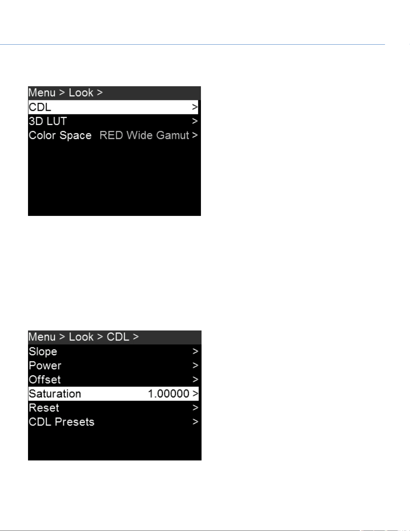
LOOK MENU
To access the Look menu, go to Menu > Look.
Figure: Look Menu
CDL
Use the CDLmenu to create and apply color-decision-list edits in-camera, with control over slope, power, offset, and
saturation. To create a CDL, follow the instructions below:
1. Go to Menu > Look > CDL.
2. Individually set the values for slope, power, offset, and saturation.
3. Select CDLPresets > In Camera.
4. Press Create.
5. Select the created CDL and press Apply.
Figure: CDL Menu
COP YRIGHT © 2020 PA N A VISION IN TERN ATION AL, L.P . FW : V-1.0.0| 67
PANAVISION MILLENNIUM DXL2

SET SLOPE
Red, green, and blue are each adjustable from 0 to 2 in increments of 0.1; the default is 1. To select a slope setting, follow the
instructions below:
1. Go to Menu > Look > CDL > Slope.
2. Select individual slope settings for red, green, and blue.
SET POWER
Red, green, and blue are each adjustable from 0 to 4 in increments of 0.1; the default is 1. To select a power setting, follow
the instructions below:
1. Go to Menu > Look > CDL > Power.
2. Select individual power settings for red, green, and blue.
SET OFFSET
Red, Green, and Blue are each adjustable from -1 to 1 in increments of 0.1; the default is 0. To select an offset setting, follow
the instructions below:
1. Go to Menu > Look > CDL > Offset.
2. Select individual settings for red, green, and blue.
SET SATURATION
Saturation is adjustable from 0 to 4 in increments of 0.1; the default is 1. To select a saturation setting, follow the instructions
below:
1. Go to Menu > Look > CDL > Saturation.
2. Select a saturation setting.
RESET CDLSETTINGS
To reset the camera's CDLsettings and return each to its default, go to Menu > Look > CDL > Reset.
CDLIMPORT/EXPORT
To export and import CDLs, go to Menu > Look > CDL > CDLPresets.
CDLs can be stored on the camera or transferred to SSD to be shared with other cameras. When exporting CDLs from the
camera to an SSD, the CDLs are saved to a folder on the SSD called "cdls". When importing CDLs from an SSD to the
camera, the CDLs must be stored on the SSD in a folder called "cdls".
NOTE:The Panavision Millennium DXL2 can also receive CDLs wirelessly from Pomfort Livegrade. In order to do this, the
camera must either be in Ad-Hoc mode (in which case the computer running Livegrade would select the camera as its WiFi
network) or be in Infrastructure mode (in which case the camera and the computer would both connect to a common access
point). For more information, go to "Network Menu" on page80.
COP YRIGHT © 2020 PA N A VISION IN TERN ATION AL, L.P . FW : V-1.0.0| 68
PANAVISION MILLENNIUM DXL2

IMPORT FROM SSDTO CAMERA
To import CDLs from an SSDto the camera, follow the instructions below:
1. Go to Menu > Look > CDL >CDLPresets.
2. Select On Media: \cdls.
3. Select one of the following:
Import
Import All
APPLY IMPORTED CDL
To apply a CDLthat has already been imported, follow the instructions below:
1. Go to Menu > Look > CDL >CDLPresets.
2. Select In Camera.
3. Scroll to the desired CDL, and then select Apply.
EXPORT FROM CAMERA TO SSD
To export CDLs from the camera to an SSD, follow the instructions below:
1. Go to Menu > Look > CDL >CDLPresets.
2. Select In Camera.
3. Select 1/2 to go to the next page.
4. Select one of the following:
Export
Export All
DELETE CDL
To delete a previously created or imported CDL, follow the instructions below:
1. Go to Menu > Look > CDL >CDLPresets.
2. Select In Camera.
3. Scroll to the desired CDL, and then select Delete.
COP YRIGHT © 2020 PA N A VISION IN TERN ATION AL, L.P . FW : V-1.0.0| 69
PANAVISION MILLENNIUM DXL2
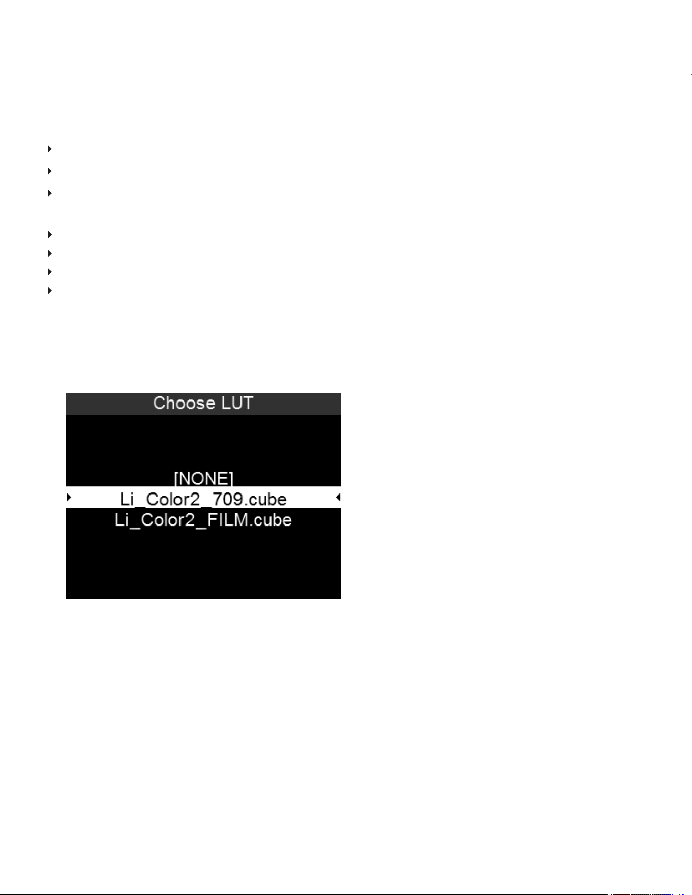
COMPATIBLE 3D LUT FORMATS
The Panavision Millennium DXL2 is compatible with the following 3D LUTs:
DaVinci Resolve
®
3D Cube LUT (.cube)
IRIDAS/Adobe
®
3D Cube LUT (.cube)
Nucoda CMS 3D LUT (.cms)
The Panavision Millennium DXL2 is compatible with the following 3D LUT formats:
17x17x17
26x26x26
32x32x32
33x33x33
APPLY A 3D LUT
To apply a 3D LUT, follow the instructions below:
1. Go to Menu > Look > 3D LUT > Choose LUT.
2. Select a LUT.
Figure: Apply 3D LUT
LUT IMPORT/EXPORT
To export and import LUTs, go to Menu > Look > 3D LUT > LUT Import/Export.
3D LUTs can be stored on the camera or transferred to SSD to be shared with other cameras. When exporting 3D LUTs from
the camera to an SSD, the 3D LUTs are saved to a folder on the SSD called “luts”. When importing 3D LUTs from an SSD to
the camera, the 3D LUTs must be stored on the SSD in a folder called “luts”.
COP YRIGHT © 2020 PA N A VISION IN TERN ATION AL, L.P . FW : V-1.0.0| 70
PANAVISION MILLENNIUM DXL2

IMPORT FROM SSD TO CAMERA
To import LUTs from an SSD to the camera, follow the instructions below:
1. Go to Menu > Look > 3DLUT > LUT Import/Export.
2. Select On Media: \luts.
3. Select one of the following:
Import
Import All
EXPORT FROM SSD TO CAMERA
To export LUTs from the camera to an SSD, follow the instructions below:
1. Go to Menu > Look > 3DLUT > LUT Import/Export.
2. Select In Camera.
3. Select one of the following:
Delete
Export
Export All
DELETING LUTS
To delete an existing LUT, follow the instructions below:
1. Go to Menu > Look > 3DLUT > LUTImport/Export.
2. Select In Camera.
3. Scroll to the desired LUT, and then select Delete.
NOTE:Light Iron Color 2 LUTs cannot be deleted.
COP YRIGHT © 2020 PA N A VISION IN TERN ATION AL, L.P . FW : V-1.0.0| 71
PANAVISION MILLENNIUM DXL2
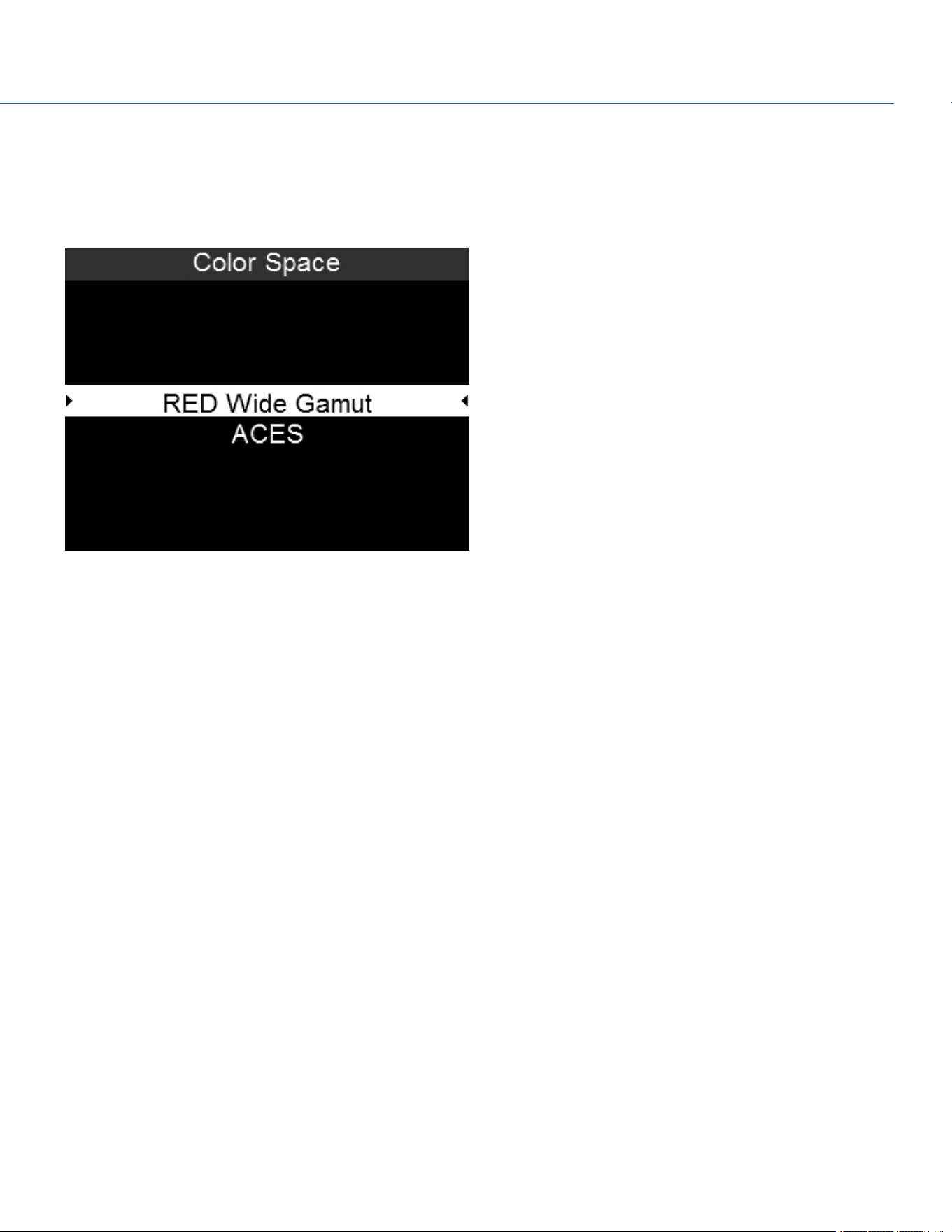
COLOR SPACE (DEFAULTS)
To set up the main output color space and gamma curve, follow the instructions below:
1. Go to Menu > Look > Color Space.
2. Select the default color space.
Figure: Color Space
NOTE:When the ACEScolor space is selected, certain features are disabled, and some menus offer different options.
COP YRIGHT © 2020 PA N A VISION IN TERN ATION AL, L.P . FW : V-1.0.0| 72
PANAVISION MILLENNIUM DXL2

USER PRESETS MENU
Figure: User Presets Menu
To access the User Presets menu, go to Menu > User Presets.
The camera has the following presets:
Camera Presets: These store and recall camera setup information, such as in-camera Looks, key mappings, I/O
configurations, and more. The camera has a number of factory-installed presets.
Looks: These allow you to save the specific color, image, white balance, and detail settings to be used for other projects.
You can create custom presets and Looks. Presets and Looks can be stored on the camera or transferred to SSD, so that you
can build a library of presets and Looks, or quickly copy presets and Looks from one camera to another via SSD.
Camera: Presets or Looks that are saved internally on the camera.
Media: Presets or Looks that are on the SSD in the path shown (for example, On Media: \presets:).
OTHER DEFAULTS
In addition to setting up presets, you can set up the following defaults in the User Presets menu:
Home Page
Key Mapping
CAMERA PRESETS
To manage camera presets, go to Menu > User Presets > Camera Presets.
CAMERA PRESET IMPORT/EXPORT
Presets can be stored on the camera or transferred to SSD to be shared with other cameras. When exporting presets from
camera to an SSD, the presets are saved to a folder on the SSD called “Presets”. When importing presets from an SSD to
camera, the presets must be stored on the SSD in a folder called “Presets”.
In Camera: Presets saved internally on the camera.
On Media: Presets saved to an SSD.
COP YRIGHT © 2020 PA N A VISION IN TERN ATION AL, L.P . FW : V-1.0.0| 73
PANAVISION MILLENNIUM DXL2

IMPORT FROM SSD TO CAMERA
To import camera presets from an SSD to the camera, follow the instructions below:
1. Go to Menu > User Presets > Camera Presets.
2. Select On Media: \presets.
3. Select one of the following:
Import
Import All
EXPORT FROM SSD TO CAMERA
To export camera presets from the camera to an SSD, follow the instructions below:
1. Go to Menu > User Presets > Camera Presets.
2. Select In Camera.
3. Select one of the following:
Delete
Export
Export All
COP YRIGHT © 2020 PA N A VISION IN TERN ATION AL, L.P . FW : V-1.0.0| 74
PANAVISION MILLENNIUM DXL2

LOOK PRESETS
To manage Look presets, go to Menu > User Presets > Look Presets.
LOOK PRESET IMPORT/EXPORT
Looks can be stored on the camera or transferred to SSD to be shared with other cameras. When exporting Looks from
camera to an SSD, the presets are saved to a folder on the SSD called “Looks”. When importing Looks from an SSD to
camera, the Looks must be stored on the SSD in a folder called “Looks”.
In Camera: Looks saved internally on the camera.
On Media: Looks saved to an SSD.
IMPORT FROM SSD TO CAMERA
To import Look presets from an SSD to the camera, follow the instructions below:
1. Go to Menu > User Presets > Look Presets.
2. Select On Media: \looks.
3. Select one of the following:
Import
Import All
EXPORT FROM SSD TO CAMERA
To export Look presets from the camera to an SSD, follow the instructions below:
1. Go to Menu > User Presets > Look Presets.
2. Select In Camera.
3. Select one of the following:
Apply
Export
Export All
Delete
COP YRIGHT © 2020 PA N A VISION IN TERN ATION AL, L.P . FW : V-1.0.0| 75
PANAVISION MILLENNIUM DXL2

HOME PAGE PRESETS
The Operator and Assistant Side UIs each have up to four (4) pages that you can scroll through by using the Left and Right
arrows. These pages are:
Home Page: This is the page that displays when the camera turns on, and displays recording information and project
settings. This page cannot be toggled on/off. For more information, go to "Home Page" on page29.
User Page: This page displays recording information, but does not display project settings. Various statuses and shortcuts
can be assigned to this page. For more information, go to "User Page" on page31.
Monitor Page:This page displays the color space, gamma curve, overlays, and LUTs applied to each monitor. For more
information, go to "Monitor Page" on page33.
Audio Page: This page displays audio information. For more information, go to "Audio Page" on page34.
SET UP PAGE PRESETS
1. Go to Menu > User Presets > Home Page.
2. Select which Side UI to set up: Operator or Assistant.
Figure: Select Which Side UI to Set Up
COP YRIGHT © 2020 PA N A VISION IN TERN ATION AL, L.P . FW : V-1.0.0| 76
PANAVISION MILLENNIUM DXL2
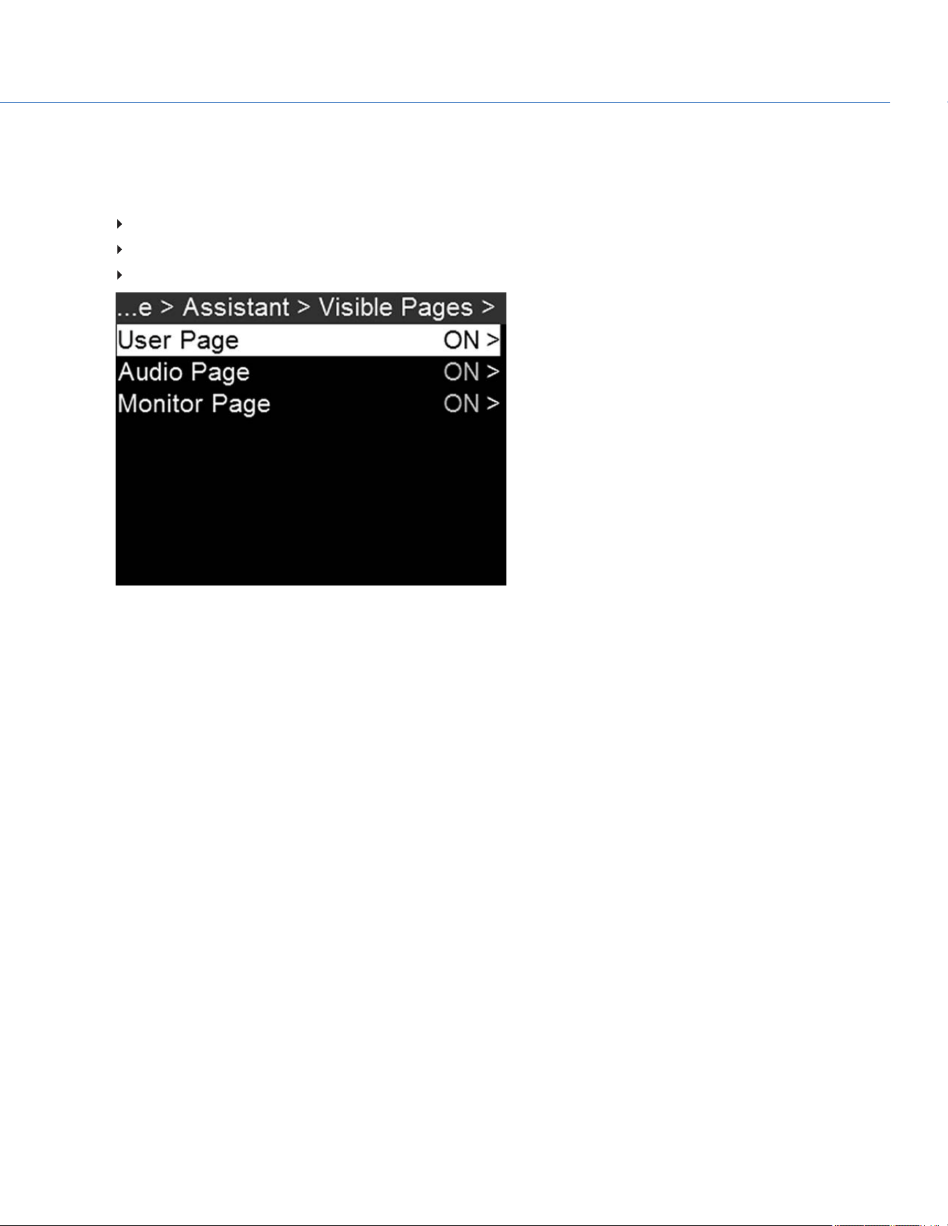
3. To set up which pages the Side UI can toggle through, follow the instructions below:
A. Select Visible Pages.
B. Toggle the following on/off:
User Page
Monitor Page
Audio Page
Figure: Toggle Pages On/Off
4. Press Back to return to the Operator or Assistant menu.
COP YRIGHT © 2020 PA N A VISION IN TERN ATION AL, L.P . FW : V-1.0.0| 77
PANAVISION MILLENNIUM DXL2
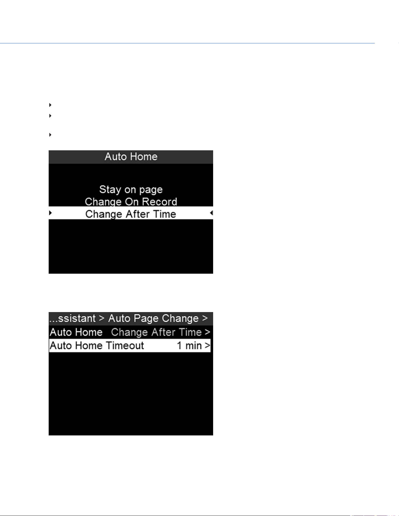
5. To set up page change information, follow the instructions below:
A. Select Auto Page Change.
B. Select Auto Home.
C. Select one of the following:
Stay on page: The home page always displays.
Change on Record: If the Side UI is not on the home page, the Side UI returns to the home page when recording
starts.
Change After Time: If the Side UI is not on the home page, the Side UI returns to the home page after the
amount of time you specify in the next step.
Figure: Select When Screen Should Return to the Home Page
D. If you selected Change after Time, return to the Auto Page Change menu, select Auto Home Timeout, and select the
timeout time.
Figure: Select When Screen Should Return to the Home Page
COP YRIGHT © 2020 PA N A VISION IN TERN ATION AL, L.P . FW : V-1.0.0| 78
PANAVISION MILLENNIUM DXL2
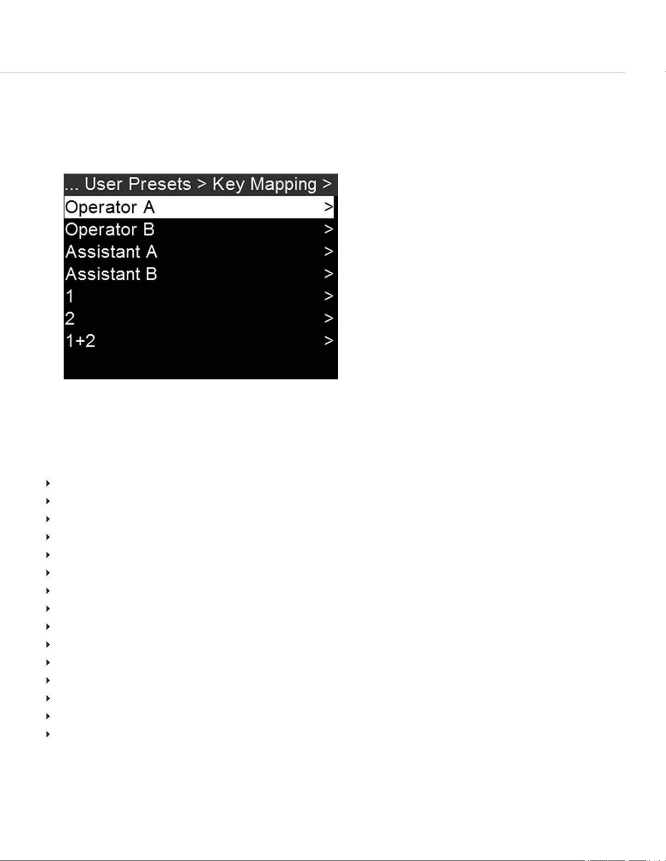
KEY MAPPING
To map or remap a user key, follow the instructions below:
1. Go to Menu > User Presets > Key Mapping.
2. Select the key you want to map.
Figure: Select When Screen Should Return to the Home Page
3. Select the action that you want to map to the key and press Enter.
ASSIGNABLE ACTIONS
You can assign the following actions to a key:
Auto WB
Black Balance
Camera Presets
Eject Media
Exposure
Format Media
Horizon
Magnify
Not Assigned
Peaking
Playback
Record Start/Stop
Return Feed
Save UI Screen Shot
Video
COP YRIGHT © 2020 PA N A VISION IN TERN ATION AL, L.P . FW : V-1.0.0| 79
PANAVISION MILLENNIUM DXL2
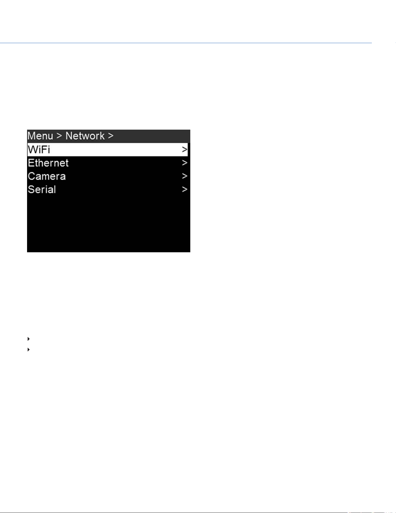
NETWORK MENU
Use the Network menu to allow one (1) or more cameras to communicate with each other or external devices.
You can use an Ethernet cable to connect two (2) cameras, or one (1) camera and one (1) external device. If the camera is
connected via Ethernet to a hub or router, multiple cameras and devices can communicate with each other.
For example, on a multi-rig 3D shoot, you can send commands to an individual camera (Example: Set CAM_A_L to 1/48
exposure), to a group of cameras (Example: Set 3DRIG_A to 48 fps), or to all cameras (Example: Start Recording on all
cameras).
Figure: Network Menu
WIFI
The camera offers a WiFi connection that provides communication support for third-party applications. The camera uses the
RED Command Protocol (R.C.P.) to communicate information between the camera and an application. As with all wireless
devices, the communication range may be affected by the environment and any radio frequency (RF) interference that may
be present. The WiFi frequency is 2.4 GHz.
There are two (2) ways to connect the camera to a device:
Ad-Hoc mode: The camera and your device connect to each other.
Infrastructure mode: The camera and your device both connect to an access point, and communicate through that
wireless network.
NOTE: To connect the camera to an app, the app must have been programmed using the R.C.P. SDK, which is available
through the R.C.P. Development Kit.
COP YRIGHT © 2020 PA N A VISION IN TERN ATION AL, L.P . FW : V-1.0.0| 80
PANAVISION MILLENNIUM DXL2
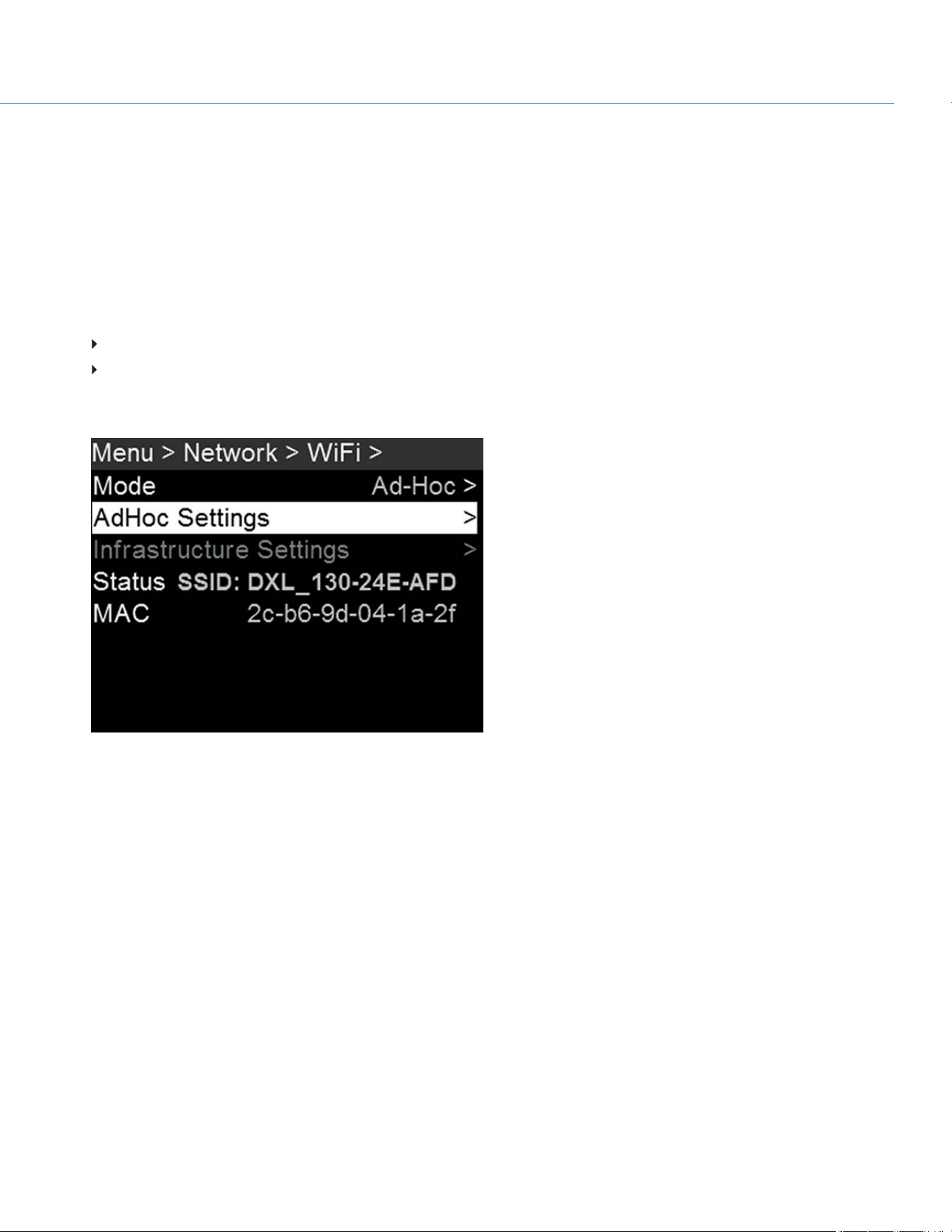
CONNECT WIRELESSLY TO A DEVICE VIA AD-HOC MODE
In Ad-Hoc mode, the camera and your device connect to each other. To connect the camera to your device via an ad-hoc
network, follow the instructions below:
1. Go to Menu > Network > WiFi.
2. Select Ad-Hoc from the Mode menu.
3. Select AdHoc Settings on the WiFi menu.
4. Select a wireless channel from the Channel menu. The default is Ch1, and you can select one out of 11 channels.
5. Select a security option from the Encryption menu:
NONE: The connection will be unsecured.
WPA2: The connection will be encrypted via WPA2.
6. If you selected WPA2 as the encryption option, type the passphrase that will be required to access the network.
7. Close the menu.
Figure: Ad-Hoc Mode
8. Connect your device to the ad-hoc network created by the camera. The steps in this procedure depend on what type of
device and operating system you are using. For example, if you are connecting an iOS device, go to Settings > Wi-Fi >
Devices, and select the camera name.
The camera name displays on the WiFi screen in-camera. The camera and your device are now connected.
NOTE: If you created a passphrase for the network, you will need to enter that passphrase. To enter the passphrase for
the network, follow the instructions below:
A. Select a security option from the Encryption menu.
B. Select Passphrase.
C. For each character in the password, use the Scroll Wheel to select a character. Turn clockwise to cycle through the
characters in this order:uppercase alphabet, lowercase alphabet, numbers 0-9, characters (#, &, etc.).
D. Press the Left and Right keys to move to the previous or next character, respectively.
E. Select Delete to delete a character.
F. Select Clear to clear the name.
G. Once you have selected the passphrase you want, press Enter.
COP YRIGHT © 2020 PA N A VISION IN TERN ATION AL, L.P . FW : V-1.0.0| 81
PANAVISION MILLENNIUM DXL2

CONNECT WIRELESSLY TO A DEVICE VIA INFRASTRUCTURE MODE
In Infrastructure mode, the camera and your device both connect to an access point, and communicate through that wireless
network. The camera can connect to access points that are not encrypted, use WPA encryption, or use WPA2 encryption. To
connect the camera to your device via an existing wireless network, follow the instructions below:
1. Connect your device to a wireless network. The access point for the network must have DHCP enabled.
2. Make sure that you know the name and password for the network, since you will need that information to connect the
camera to the same network.
3. Go to Menu > Network > WiFi.
4. Select Infrastructure from the Mode menu.
6. Select Infrastructure Settings on the WiFi menu.
Figure: Infrastructure Mode
7. Select Access Points.
8. Select Scan to search for available wireless networks.
The available wireless networks (access points) display.
9. Highlight the wireless network that your device is connected to and select Select.
8. If you select an encrypted network, follow the instructions below to enter the passphrase for the network:
A. Select a security option from the Encryption menu.
B. Select Passphrase.
C. For each character in the password, use the Scroll Wheel to select a character. Turn clockwise to cycle through the
characters in this order: uppercase alphabet, lowercase alphabet, numbers 0–9, characters (#, &, etc.).
D. Press the Left and Right keys to move to the previous or next character, respectively.
E. Select Delete to delete a character.
F. Select Clear to clear the name.
G. Once you have selected the passphrase you want, press Enter.
9. To enable/disable DHCP, select IP Config and set up the IP settings.
COP YRIGHT © 2020 PA N A VISION IN TERN ATION AL, L.P . FW : V-1.0.0| 82
PANAVISION MILLENNIUM DXL2
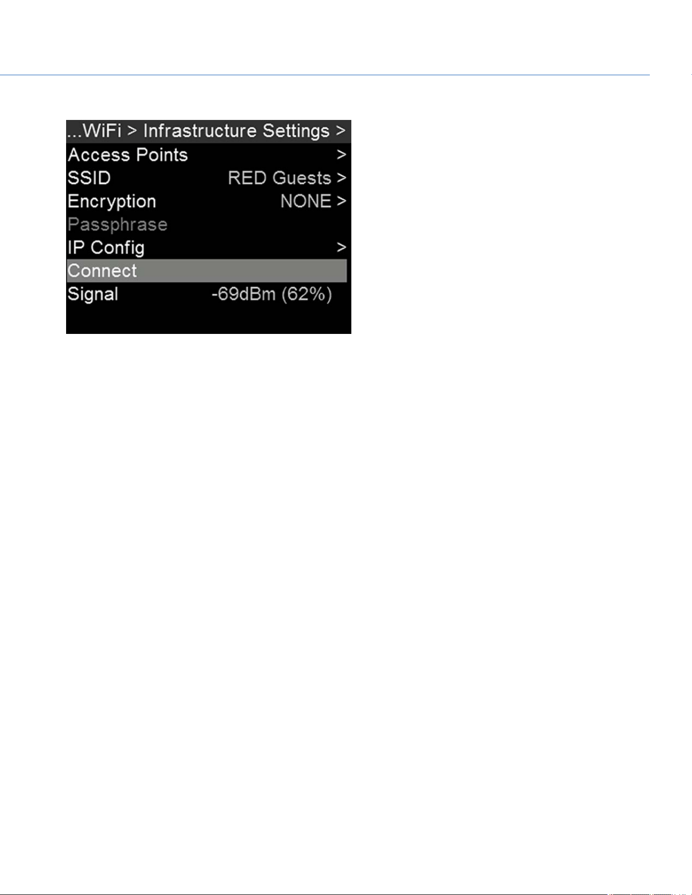
10. In the Infrastructure menu, select Connect, and then select Connect again.
Figure: Connect to Network
11. Connect your device to the same wireless network that the camera is connected to. The steps in this procedure depend
on what type of device and operating system you are using. For example, if you are connecting an iOS device, go to
Settings > Wi-Fi, and select the wireless network.
The camera and your device are now connected.
12. To ensure that your app can communicate with the camera, ensure that there is a way to connect your app to a specific
camera. Since there may be multiple cameras in the area, select your specific camera in the app itself.
COP YRIGHT © 2020 PA N A VISION IN TERN ATION AL, L.P . FW : V-1.0.0| 83
PANAVISION MILLENNIUM DXL2
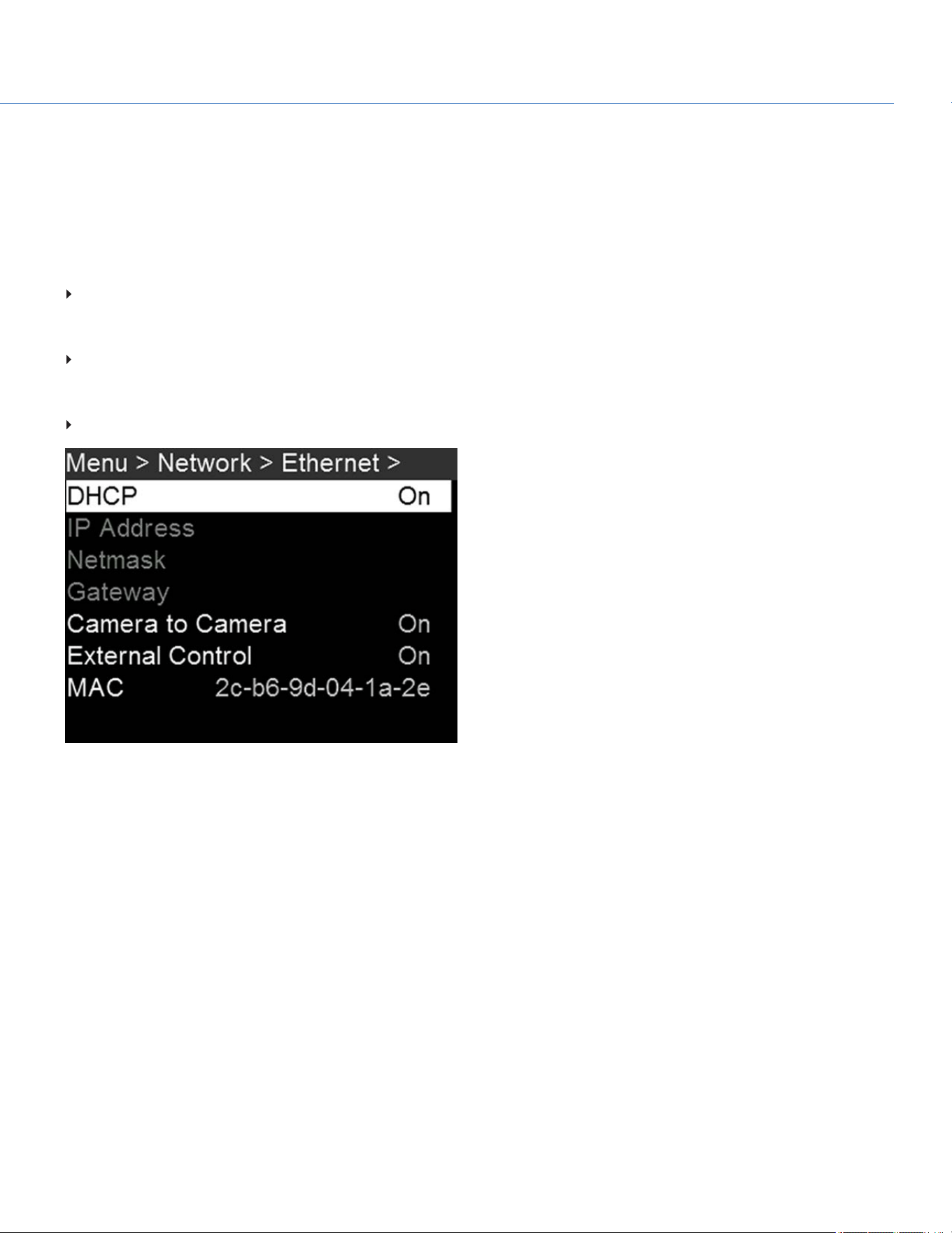
ETHERNET
To access Ethernet settings, go to Menu > Network > Ethernet.
Use the settings in the Ethernet menu to configure the GIG-E port. Each camera or device requires a unique IP address. For
camera-to-camera communication via Ethernet, both cameras need to be in the same sub-net (have the same netmask
address) and have the same gateway address.
In the Ethernet menu, you can enable/disable the following:
DHCP: Enables DHCP. If a DHCP-server is available in the communications network, the camera obtains an IP address,
netmask address, and gateway address automatically from the DHCP server. You cannot manually enter anything in the IP
Address, Netmask, and Gateway fields when DHCP is enabled.
Camera to Camera: A change to settings on this camera is sent to other cameras via the network as a SET command (as
UDP packets). The SET command then sets the property on other cameras. If this camera receives a SET command, the
camera does not send the command to other cameras/devices.
External Control: This camera can be controlled via TCP/IP from an external device.
Figure: Ethernet Menu
COP YRIGHT © 2020 PA N A VISION IN TERN ATION AL, L.P . FW : V-1.0.0| 84
PANAVISION MILLENNIUM DXL2
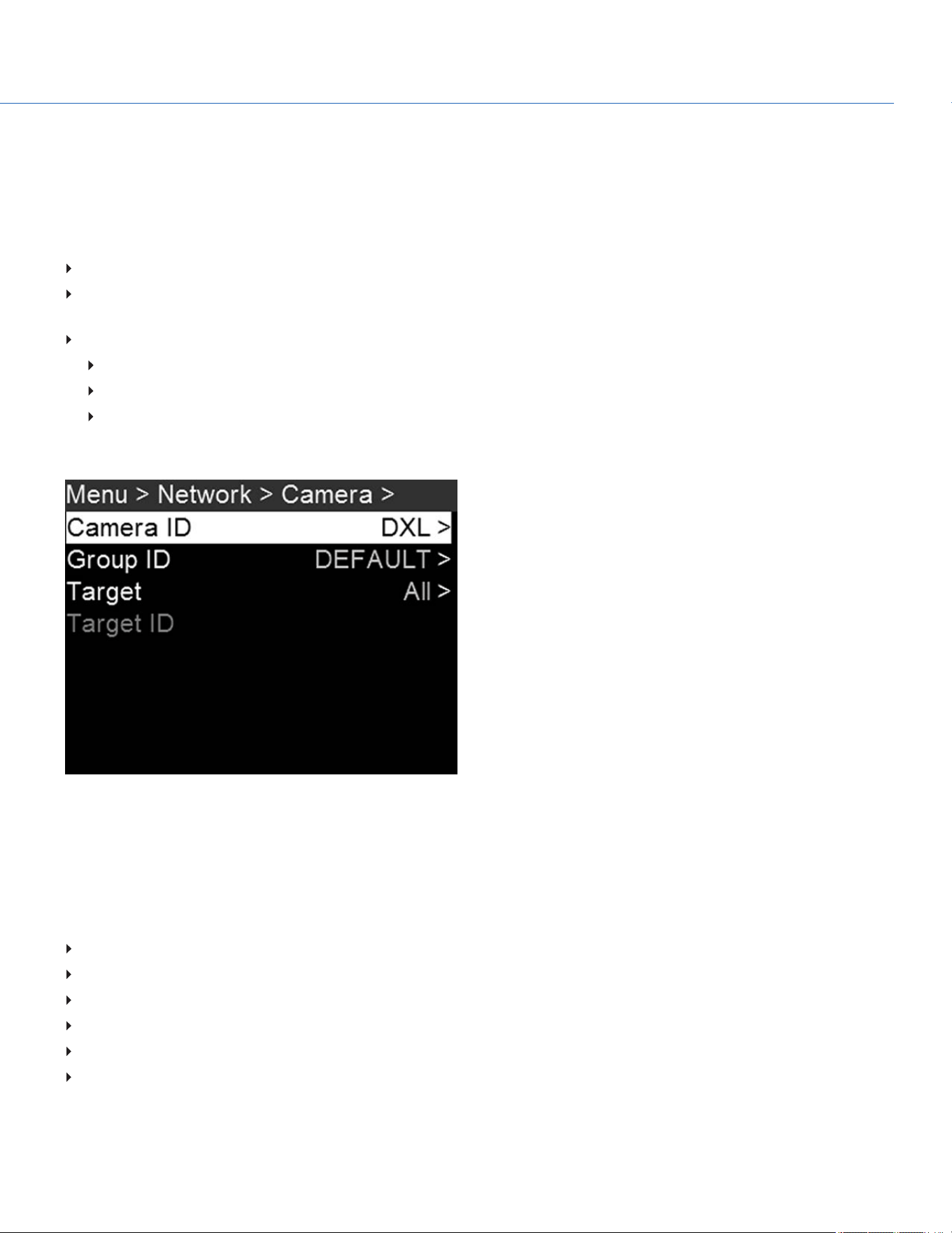
CAMERA
To access the Camera menu, go to Menu > Network > Camera.
Use the Camera menu to set up a unique identifier for your camera (or a group of cameras). All command filtering happens
on the receiver side of the communication link. Use camera names and group names to address commands to a specific
camera or group of networked cameras.
Camera ID: Enter a unique camera name to use in network communications. The field is limited to eight (8) characters.
Group ID: Enter a group name to identify the camera as a member of a group of devices. The field is limited to eight (8)
characters, and the default name is DEFAULT.
Target: Specify which devices the camera can send commands to:
All: The camera can send commands to all devices on the network.
None: The camera can only receive commands. The camera cannot send commands.
Custom: The camera can send commands to a specific camera/device (enter the name of the camera/device in the
Target ID menu) or a specific group (enter the name of the group in the Target ID menu). The camera/group name
must match the name entered in the Camera/Group field of the target device(s).
Figure: Camera Menu
SERIAL
To access the Serial menu, go to Menu > Network > Serial.
The camera can communicate to external devices via the GIG-E connector.
Select one of the following protocols from the Ctrl Protocol menu:
None (Default)
Element Technica
3ality SPC 7XXX
RED Command Protocol
Camera to Camera
Preston
COP YRIGHT © 2020 PA N A VISION IN TERN ATION AL, L.P . FW : V-1.0.0| 85
PANAVISION MILLENNIUM DXL2
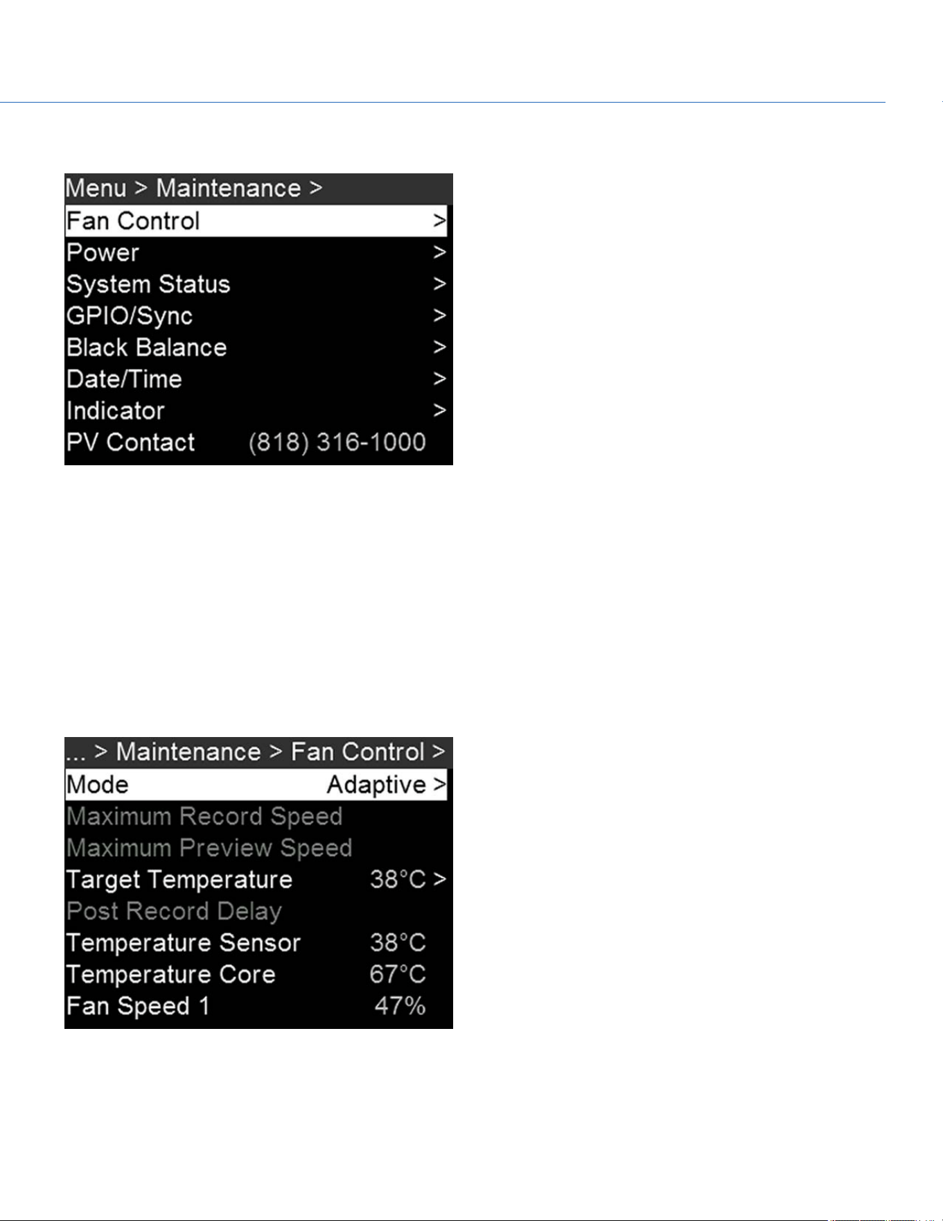
MAINTENANCE
Figure: Maintenance Menu
FAN AND TEMPERATURE MANAGEMENT
To select a fan control mode, see the current camera temperatures (sensor and core), and see the current fan speeds, go to
Menu > Maintenance > Fan Control.
The camera is controlled by complex thermal algorithms to ensure that the sensor and camera operate at safe temperatures.
Each fan control mode affects the sensor temperature, sensor warm-up time, fan speed, and resulting fan noise.
When selecting a fan mode, first take into consideration how each fan mode behaves, and then select a fan mode that fits
the needs of your project.
Regardless of sensor type and fan mode, you will get the best image quality by calibrating the sensor at the temperature you
want to use for your shoot.
Figure: Fan Control Menu
COP YRIGHT © 2020 PA N A VISION IN TERN ATION AL, L.P . FW : V-1.0.0| 86
PANAVISION MILLENNIUM DXL2

FAN CONTROL MODES
Select a fan control mode.
NOTE: After selecting a new fan setting, run the camera until the core temperature stabilizes, and then calibrate the sensor.
NOTE: Manual mode requires that you actively manage the sensor temperature, because this mode focuses on controlling fan
speed and does not target a narrow sensor temperature range. Use the T/E status indicators as guides for proper temperature
calibration.
NOTE: Maximum speeds are intended as target speeds only; actual fan speeds may be higher at times due to long recording
times or high ambient temperatures.
ADAPTIVE (TARGET TEMPERATURE)
Adaptive is the default mode for the camera.
Select a Target Temperature and the fans self-adjust to maintain the selected temperature. The default Target Temperature
is 39°C. After the camera reaches the Target Temperature, and if the ambient temperature remains constant, Adaptive mode
results in a consistent fan speed and fan noise over time.
Targeting a higher temperature raises the sensor temperature, lengthens the sensor warm-up time, and lowers the fan speed.
Targeting a lower temperature lowers the sensor temperature, shortens the sensor warm-up time, and increases the fan
speed.
NOTE: The intent of Target Temperature is to set the sensor temperature so that you can then create a calibration map for
that temperature.
NOTE: When the camera turns on, the Target Temperature is the temperature of the current calibration map, regardless of
what the Target Temperature was before you turned off the camera. Setting a calibration map also overrides the Target
Temperature. For more information, go to "Sensor Calibration" on page94.
ADAPTIVE PREVIEW QUIET RECORD
Record mode: The camera uses Quiet fan mode. For more information, go to "Quiet" below.
Standby mode: The camera uses Adaptive fan mode. For more information, go to "Adaptive (Target Temperature)" above.
QUIET
The fans self-adjust to maintain the lowest possible noise level in record and standby mode while still cooling the camera.
MANUAL
Select a speed for the fans in both record and standby modes. The fans self-adjust to maintain the selected speeds. The
default Maximum Record Speed is 75% and the default Maximum Preview Speed is 75%. The range for both Maximum
Record Speed and Maximum Preview Speed is 25–100%.
POST RECORD DELAY
Select the amount of time that it takes for the fan to switch from record to preview mode.
COP YRIGHT © 2020 PA N A VISION IN TERN ATION AL, L.P . FW : V-1.0.0| 87
PANAVISION MILLENNIUM DXL2
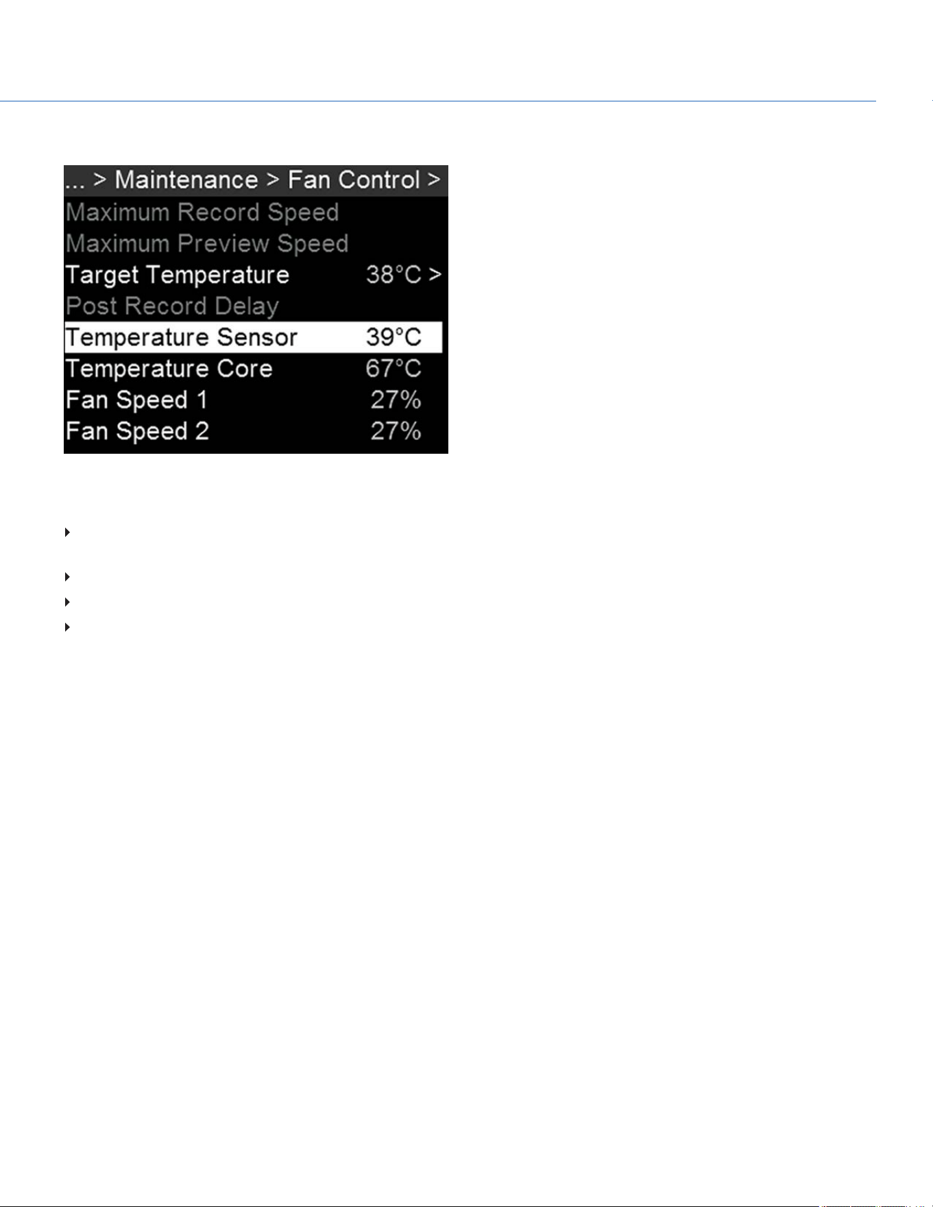
TEMPERATURE AND FAN STATUS
Figure: Temperature and Fan Statuses
The Fan Control menu displays the following statuses:
Temperature Sensor: The current temperature of the sensor. This is the temperature directly affected by the Target
Temperature setting.
Temperature Core: The current temperature of the camera core.
Fan Speed 1: The fan speed, measured as the percentage of the maximum speed of the fan.
Fan Speed 2: The fan speed, measured as the percentage of the maximum speed of the fan.
COP YRIGHT © 2020 PA N A VISION IN TERN ATION AL, L.P . FW : V-1.0.0| 88
PANAVISION MILLENNIUM DXL2
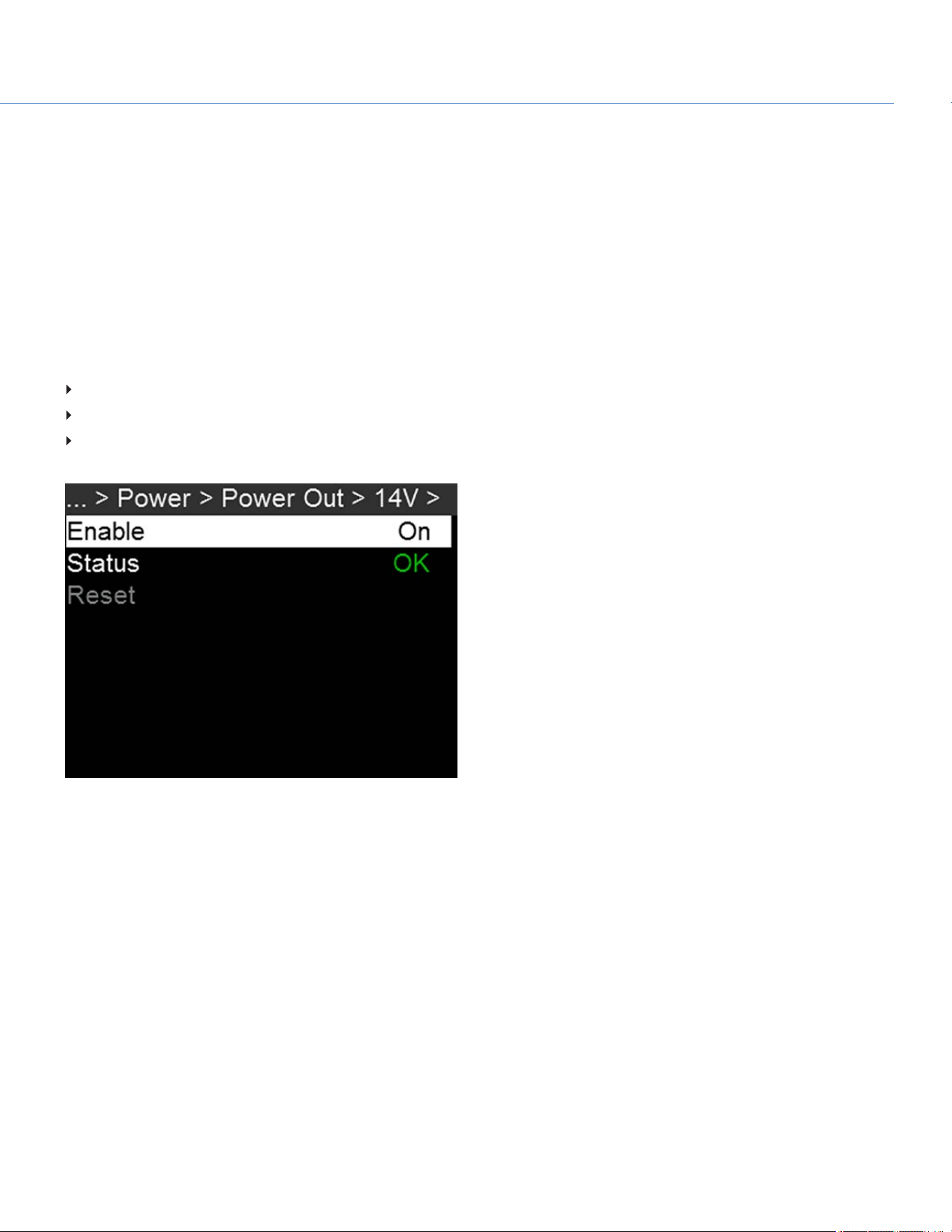
POWER MENU
The Power menu displays the power status of all attached power sources.
POWER IN
The power status displays for all attached power devices. The menu displays the voltage of the source or the relative
percentage of the power left, as well as the time left, if applicable.
POWER OUT
The Power Out menu shows the status of the power-out ports on the camera. In this menu, you can also enable/disable each
power-out port. The statuses are:
N/A: The device is not present.
OK: The power-out port is functional.
FAULT: A short or overcurrent tripped the electronic fuse. Remove the device that is connected to the port, as it may be
drawing too much power. Select RESET to clear the fault.
Figure: Power Out
COP YRIGHT © 2020 PA N A VISION IN TERN ATION AL, L.P . FW : V-1.0.0| 89
PANAVISION MILLENNIUM DXL2
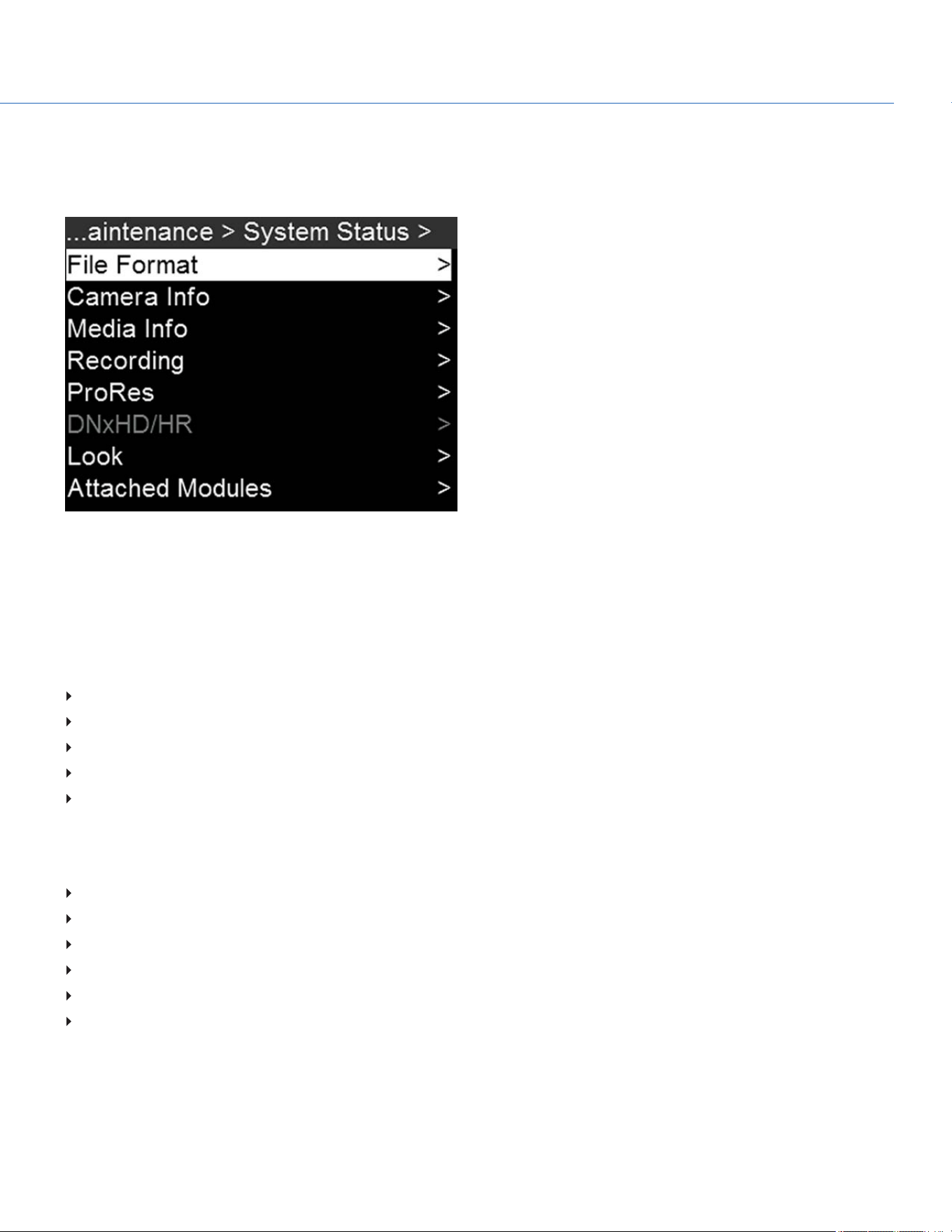
SYSTEM STATUS
The System Status menu displays key project and system information. To access the System Status menu, go to Menu >
Maintenance > System Status.
Figure: System Status
FILE FORMAT
Displays the file formats that are currently enabled. To change the file format, go to "Select Record File Format" on page50.
CAMERA INFO
Displays the following camera information:
Type: Camera type.
Firmware Version: Current firmware version.
PIN: The personal identification number that is specific to your camera.
SVN Revision: The current firmware number.
Runtime: The number of hours that the camera has been turned on.
MEDIA INFO
Displays the following media information:
Active Media
Model Number
Serial Number
Firmware Version
Size
Size Available
COP YRIGHT © 2020 PA N A VISION IN TERN ATION AL, L.P . FW : V-1.0.0| 90
PANAVISION MILLENNIUM DXL2

RECORDING
Displays the following recording information:
Format
Recording Frame Rate
Project Time Base
REDCODE
To change the recording information, go to "Project Settings" on page42.
PRORES
This status menu is available only if recording to an Apple ProRes codec is enabled.
Displays the following codec information:
Video Codec
Resolution
Frame Rate
To change the recording information, go to "Project Settings" on page42.
DNXHD/HR
This status menu is available only if recording to an Avid codec is enabled.
Displays the following codec information:
Video Codec
Resolution
Frame Rate
To change the recording information, go to "Project Settings" on page42.
LOOK
Displays the following information:
Color Temperature
Tint
ISO
ATTACHED MODULES
Lists all attached modules.
COP YRIGHT © 2020 PA N A VISION IN TERN ATION AL, L.P . FW : V-1.0.0| 91
PANAVISION MILLENNIUM DXL2

OTHER
Displays the following information:
Timecode Display Mode:To change this, go to "Timecode" on page55.
Timecode Status
Slate Camera Position: To change this, go to "Slate" on page53.
Slate Camera ID: To change this, go to "Slate" on page53.
Sync Status
Genlock Status
OLPF Type
Calibration Temperature
Calibration Integration Time
CONNECTED RCP CLIENTS
Lists any RCP clients the camera is connected to.
COP YRIGHT © 2020 PA N A VISION IN TERN ATION AL, L.P . FW : V-1.0.0| 92
PANAVISION MILLENNIUM DXL2
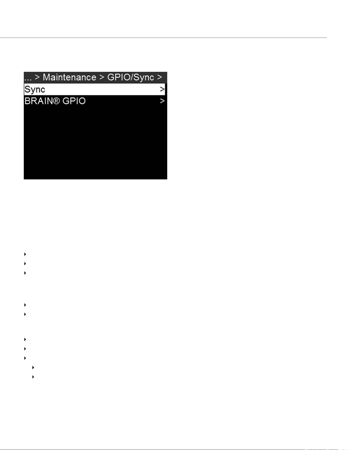
GPIO SYNC
To access the GPIO/Sync menu, go to Menu > Maintenance > GPIO/Sync.
Figure: GPIO/Sync Menu
SYNC
Use the Sync menu to set up genlock and Motion Control (MoCo). For more information, go to "Timecode, Genlock, Multi-
Camera Setup" on page114.
SENSOR SYNC MODE
Sensor Sync Mode allows the shutter timing (scan start) to sync to an external signal.
Off: Sensor runs at the current recording frame rate. This is the default option.
Genlock: Sensor synchronizes with the incoming compatible genlock signal.
MoCo: Each rising edge on the sync input triggers a frame to be captured.
GENLOCK SOURCE
Select a genlock input:
BRAIN (Default)
Rear Module
BRAIN GPIO
BRAINGPI in High: Map an action to the release of a trigger or off position of a switch.
BRAINGPI in Low: Map an action to the press of a trigger or on position of a switch.
GPO Function (Camera Output): Select an option to configure the output for devices connected to the camera:
Sync Out: Provides an output sync signal to act as a shutter start tally.
Recording Indicator Out: Provides a signal when recording is in process.
For more information, go to Input/Output Connectors.
COP YRIGHT © 2020 PA N A VISION IN TERN ATION AL, L.P . FW : V-1.0.0| 93
PANAVISION MILLENNIUM DXL2

SENSOR CALIBRATION
Sensor calibration, also known as black balance, is a process during which the camera optimizes image quality by ensuring
that pixel sensitivity remains consistent throughout the sensor. Calibrating the sensor generates a calibration map based on
system and environment settings. After calibration, the sensor shows a uniform noise profile over the whole area without any
falloffs on any side.
NOTE: Calibration maps are still available after performing a system restore.
WHEN TO CALIBRATE SENSOR
Calibration is required:
After an extreme change in temperature (+/– 30°F or +/–15°C) from the current calibration map.
After an extreme change in exposure time (+/– 1/2 sec) from the current calibration map.
If either the T or E in the CAL: T/E indicator is not green.
After each firmware upgrade.
To check the temperature/exposure of the current calibration file, go to Menu > Maintenance > System Status > Other.
BLACK BALANCE: CALIBRATE SENSOR AT CURRENT SETTINGS
The camera calibrates the sensor at the current exposure and temperature setting. You will need to re-calibrate the sensor
after extreme changes in exposure and temperature. The process takes several minutes.
To calibrate the sensor, follow the instructions below:
1. Ensure that the camera reaches the temperature you want to use for your shoot.
2. Set the exposure to the exposure you want to use for your shoot.
3. Ensure that the sensor is as dark as possible.
Preferably, take off the lens, and install the front body cap.
If you cannot take off the lens, put a lens cap on the lens. (Not all lens caps completely block IR. Lens caps are made
to protect the lens, not necessarily to block light.)
If possible, use a dark room.
Just closing the aperture is NOT sufficient.
4. Go to Menu > Maintenance > Black Balance.
COP YRIGHT © 2020 PA N A VISION IN TERN ATION AL, L.P . FW : V-1.0.0| 94
PANAVISION MILLENNIUM DXL2

5. Select Current Settings.
Figure: Select Current Settings
6. Select Start.
7. Select OK to continue. The system initializes and then makes multiple passes through the following phases of the
calibration:
Capturing
Analyzing
Erasing
Programming
8. When the Calibration Successful dialog displays, select OK to complete the process.
The new calibration map is automatically selected.
COP YRIGHT © 2020 PA N A VISION IN TERN ATION AL, L.P . FW : V-1.0.0| 95
PANAVISION MILLENNIUM DXL2
CALIBRATION MAP NAMING CONVENTIONS
Each calibration map has a unique name that uses the format described in the table below:
NAME DESCRIPTION EXAMPLE
Exposure Current exposure; to set exposure, go to "Exposure/Shutter" on page54 48
Sensor
Temperature
Sensor temperature (Celsius); in the Lower Status Row, this is the number to the left of the
forward slash (Temp: 34/35)
32C
Year Year that the calibration map is created (yyyy) 2014
Month Month that the calibration map is created (mm) 01
Day Day that the calibration map is created (dd) 28
Time Time according to the 24-hour clock in the camera (hhmmss) 122150
For example, a sequence of calibration maps may look like this:
1. 48_32C_20140128122150
2. 72_34C_20140128122858
3. 120_41C_20140128124306
NOTE: If you mount an SSD with calibration files to your computer, each calibration map displays as a sub-folder in a folder
called Calibration. To save a calibration map to your hard drive, copy the entire sub-folder (for example, 48_ 32C_
20140128122150) to your drive.
COP YRIGHT © 2020 PA N A VISION IN TERN ATION AL, L.P . FW : V-1.0.0| 96
PANAVISION MILLENNIUM DXL2
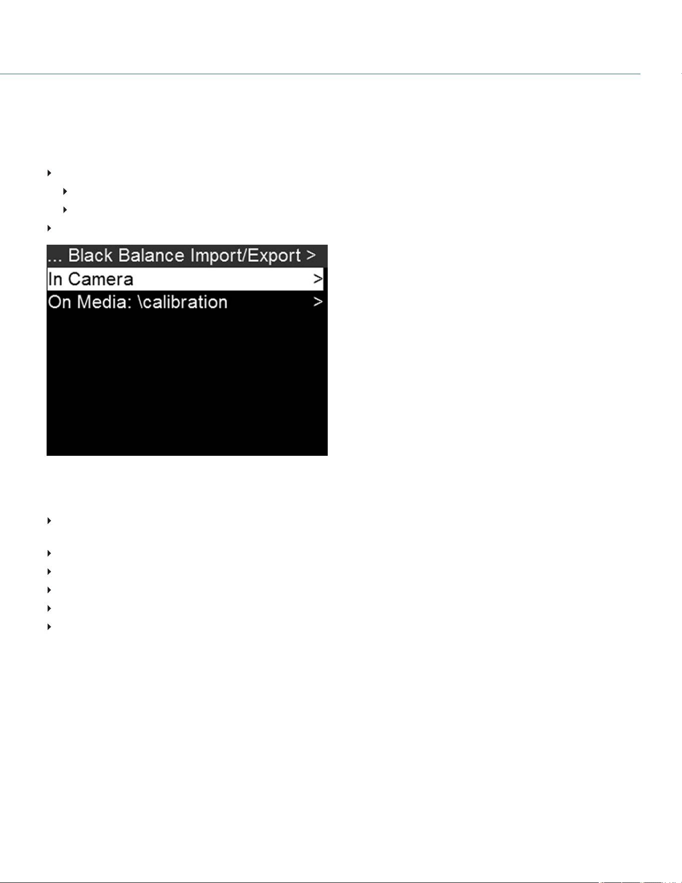
CALIBRATION MANAGEMENT
NOTE: The camera can store a limited amount of calibration maps. (You may need to delete older maps in order to create
new maps.) Calibration maps can also be transferred to SSD to be shared with other cameras.
To apply, export, and import calibration maps, go to Menu > Maintenance > Black Balance > Black Balance Import/Export.
In Camera: The calibration maps that are saved internally on the camera:
Factory: This is the calibration map generated during the manufacturing process. (Default)
All other: The user-created calibration maps.
On Media: The calibration maps that are on the SSD in the path shown (for example, S-SSD\calibration).
Figure: Import/Export Calibration Files
CALIBRATION MAP ACTIONS
Apply: Apply the selected calibration map (if the calibration map is on the SSD, the camera applies the map temporarily,
and does not import it into the camera).
Export: Export selected calibration map from camera to SSD.
Export All: Export all files from camera to SSD.
Import: Import selected calibration map from SSD to camera.
Import All: Import all files from SSD to camera.
Delete: Delete the selected camera calibration map. You cannot delete the factory map.
COP YRIGHT © 2020 PA N A VISION IN TERN ATION AL, L.P . FW : V-1.0.0| 97
PANAVISION MILLENNIUM DXL2

DATE/TIME
Use the Date/Time menu to reset the internal clock of the camera. The time and date are timestamps on R3D files when
recording to an SSD. The camera uses the 24-hour clock convention (military time). For example, enter 2:35 p.m. as 14:35:00.
The date and time are saved when you close the Date/Time menu.
Figure: Date/Time
COP YRIGHT © 2020 PA N A VISION IN TERN ATION AL, L.P . FW : V-1.0.0| 98
PANAVISION MILLENNIUM DXL2

INDICATOR
To access the Indicator menu, go to Menu >Maintenance > Indicator.
Enable Sounds: Select to enable sounds. Then select sounds for the following actions:
Record Start
Record Stop
Tag Still Frame
EVF Tally Light: Enable the EVF Record Tally LED on the EVF to illuminate red when recording.
SSD Tally Light: Enable the Record Tally LED on the media bay to illuminate red when recording. For more information, go
to "Left Side (Operator Side) LEDs" on page13.
Figure: Indicator Menu
PV CONTACT
This is the phone number for the Panavision office in Woodland Hills, CA: (818) 316-1000.
COP YRIGHT © 2020 PA N A VISION IN TERN ATION AL, L.P . FW : V-1.0.0| 99
PANAVISION MILLENNIUM DXL2
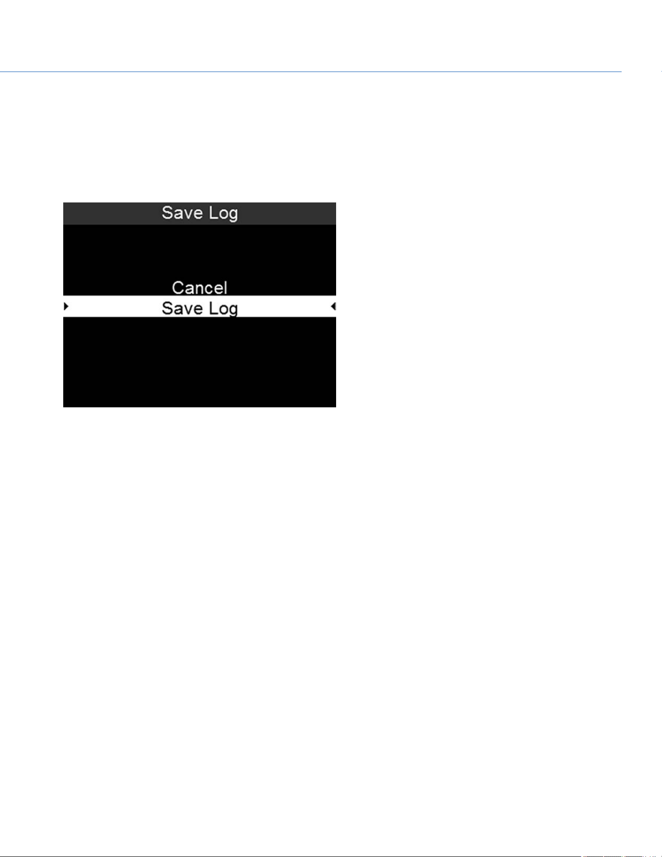
SAVE A LOG FILE
A log file is a detailed text file of the processes and operations performed by the camera. If you contact support, you may be
asked to send a log file.
To save a log file, follow the instructions below:
1. Ensure that an SSD is properly mounted to the camera.
2. Go to Menu > Maintenance > Save Log.
Figure: Save Log
3. Select Save Log.
The log file is saved as a *.txt file in the SSD root directory.
NOTE: The camera automatically saves a log file when it is turned off properly and an SSD is mounted.
COP YRIGHT © 2020 PA N A VISION IN TERN ATION AL, L.P . FW : V-1.0.0| 100
PANAVISION MILLENNIUM DXL2
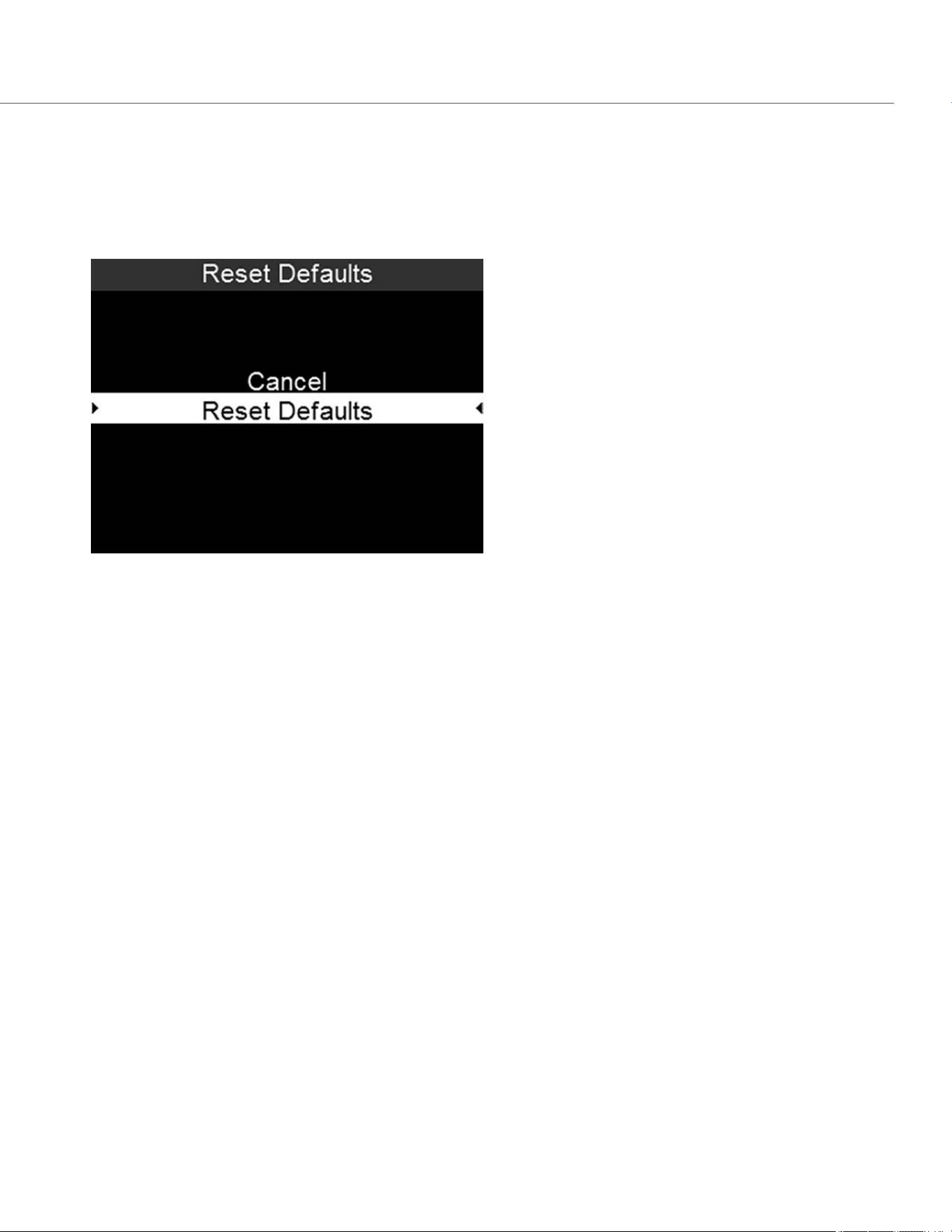
CAMERA DEFAULT
RESET DEFAULTS
Reset Defaults changes all settings to the factory default values. To perform a Reset Defaults, follow the instructions below:
1. Go to Menu > Maintenance > Camera Defaults > Reset Defaults.
Figure: Reset Defaults
2. Select Reset Defaults.
3. Select YES on the screen that asks you to confirm the action.
The camera turns off.
4. Turn on the camera.
COP YRIGHT © 2020 PA N A VISION IN TERN ATION AL, L.P . FW : V-1.0.0| 101
PANAVISION MILLENNIUM DXL2

WIPE CAMERA
Wipe Camera deletes all user settings, including: calibration files, overlays, presets, and LUTs. Wipe Camera restores all
factory defaults.
1. Go to Menu > Maintenance > Camera Defaults > Wipe Camera.
Figure: Wipe Camera
2. Select Wipe Camera.
3. Select YES on the screen that asks you to confirm the action.
The camera turns off.
4. Turn on the camera.
COP YRIGHT © 2020 PA N A VISION IN TERN ATION AL, L.P . FW : V-1.0.0| 102
PANAVISION MILLENNIUM DXL2
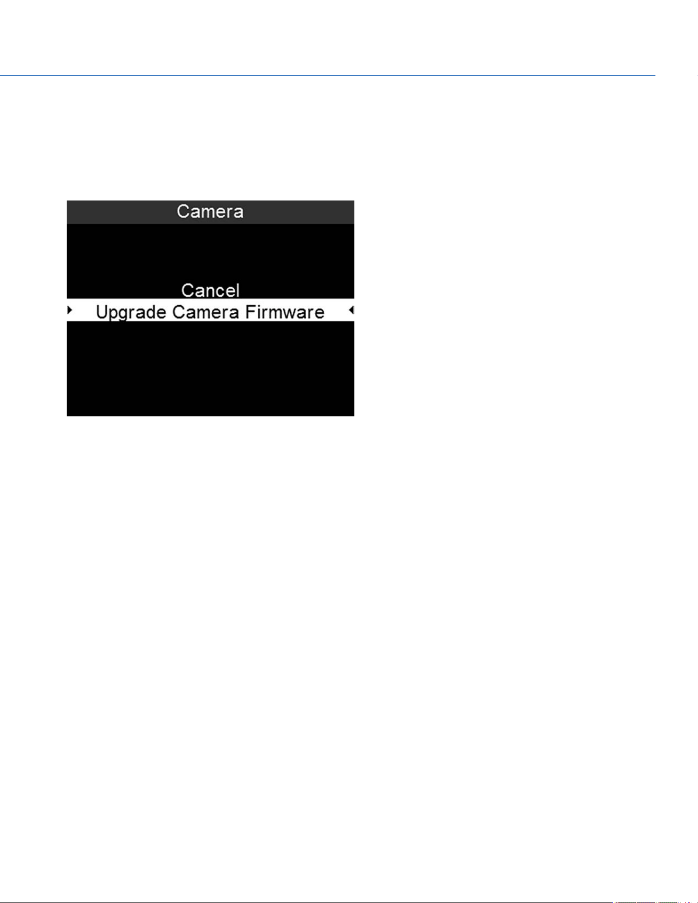
UPGRADE
If there is an upgrade package on a mounted SSD, you can initiate a firmware upgrade from within the menu:
1. Go to Menu > Maintenance > Upgrade.
2. Select Camera.
3. Select Upgrade Camera Firmware.
Figure: Upgrade Camera Firmware
COP YRIGHT © 2020 PA N A VISION IN TERN ATION AL, L.P . FW : V-1.0.0| 103
PANAVISION MILLENNIUM DXL2

PLAYBACK
NOTE: Clips captured in RAW with a 3DLUTapplied during recording will play back with the same LUTapplied; the
LUTcannot be changed for playback. 3DLUTs cannot be applied in Playback mode for non-RAW clips.
To view clips from the SSD, follow the instructions below:
From the Home Page, select Playback.
Use the Navigation Wheel or the selection keys to select the clip you want to view.
First Clip:Goes to the first clip on the SSD.
Last Clip:Goes to the last clip on the SSD.
Select Play (the lower-right selection key) or Enter.
COP YRIGHT © 2020 PA N A VISION IN TERN ATION AL, L.P . FW : V-1.0.0| 104
PANAVISION MILLENNIUM DXL2
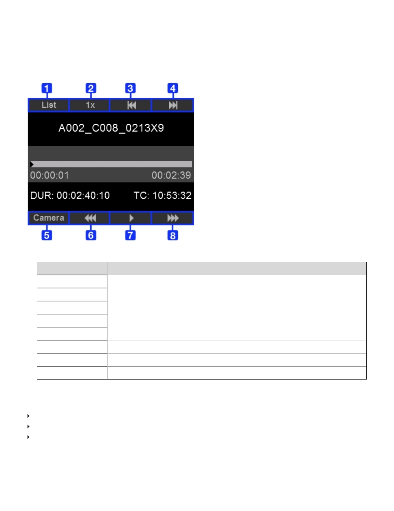
PLAYBACK STATUS BAR
Displays the progress of the clip during playback. Use the selection keys to control playback, as described in the table below.
Figure: Playback Status Bar
# CONTROL DESCRIPTION
1 List Returns to the list of clips.
2 Speed Indicates the playback speed. Not an operable key.
3 Previous clip Goes to the previous clip.
4 Next clip Goes to the next clip.
5 Camera Exits Playback mode.
6 Reverse Adjusts the playback speed (from -1x to -16x) when playing backward through the clip.
7 Play/Pause Pauses and resumes playback.
8 Forward Adjusts the playback speed (from 1x to 16x) when playing forward through the clip.
EXIT PLAYBACK MODE
Perform one of the following actions to exit Playback mode:
Press Camera.
Press Menu.
Press Record. (You can also press any button mapped to Record to exit Playback mode.)
COP YRIGHT © 2020 PA N A VISION IN TERN ATION AL, L.P . FW : V-1.0.0| 105
PANAVISION MILLENNIUM DXL2
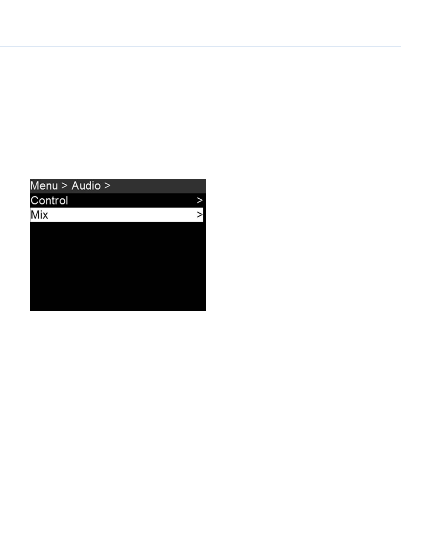
COP YRIGHT © 2020 PA N A VISION IN TERN ATION AL, L.P . FW : V-1.0.0| 106
PANAVISION MILLENNIUM DXL2
AUDIO SYSTEM
AUDIO OVERVIEW
The camera has two (2) integrated dual channel digital stereo microphones that record uncompressed audio at 24-bit 48 kHz.
These microphones offer you the ability to capture scratch-track audio.
Most controls in the Audio menu (Menu > Audio) are only applicable when an audio module is attached.
Input signals are routed via a high-quality pre-amplifier to achieve the desired recording levels and maximize dynamic range.
Audio data is synchronized with video and timecode and embedded in the R3D
®
file.
Audio is also embedded in any HD-SDI output connected to the camera.
Figure: Audio Menu
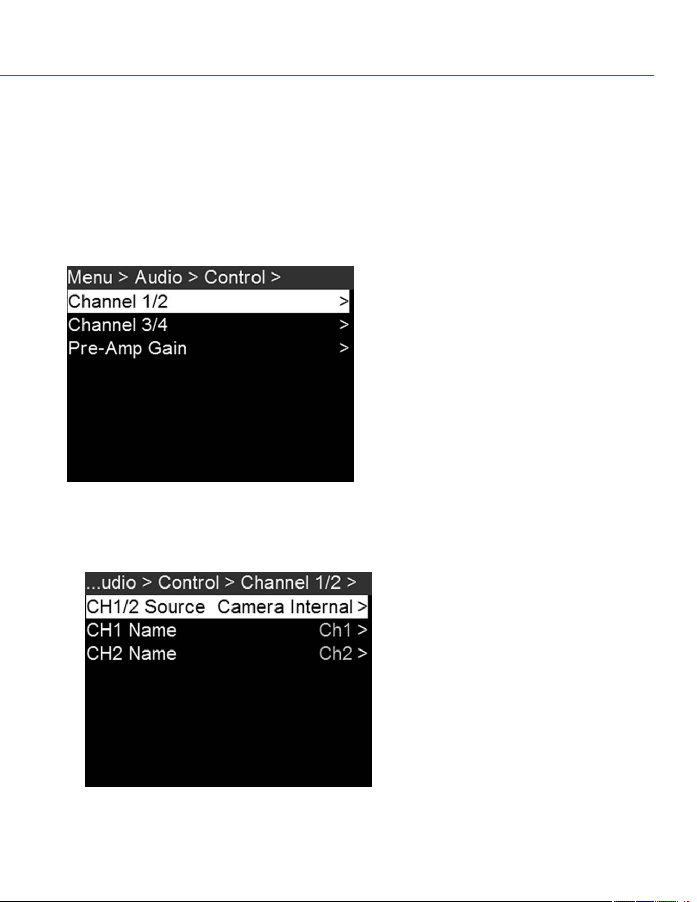
CONTROL
To adjust the input and pre-amplifier, go to Menu > Audio > Control.
CHANNEL SOURCES AND NAMES
You can rename each audio channel, and each name can be any alphanumeric combination, up to six (6) characters. The
default channel names are Ch1, Ch2, Ch3, and Ch4. The channel names display in the Audio Meter, but are not included in
the clip metadata.
1. To set up the audio channels, go to Menu > Audio > Control.
2. Select the channels you want to set up: Channel 1/2 or Channel 3/4.
Figure: Control Menu
3. Set the channel source:
A. Select Ch X/X Source.
B. Select a source: None or Camera Internal.
Figure: Select Audio Source for Channel
C. Press Enter.
COP YRIGHT © 2020 PA N A VISION IN TERN ATION AL, L.P . FW : V-1.0.0| 107
PANAVISION MILLENNIUM DXL2
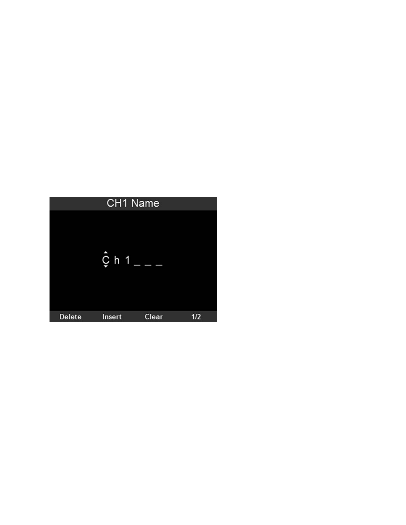
4. Set the channel name:
A. Select CHX Name.
NOTE: Select 1/2 or 2/2 in the bottom right of the screen to toggle between the first and second page of menu
options.
B. For each character available, use the Scroll Wheel to select a character. Turn counterclockwise to cycle through the
characters in this order: uppercase alphabet, lowercase alphabet, numbers 0–9.
C. Press the Left and Right keys to move to the previous or next character, respectively.
D. Select Delete to delete a character.
E. Select Insert to insert a character (up to 6 characters available); selecting insert re-starts at A.
F. Select Clear to clear the name.
G. Select Begin to move the cursor to the first character.
H. Select End to move the cursor to the last (sixth) character.
I. Once you have selected the name you want, press Enter.
Figure: Select Channel Name
COP YRIGHT © 2020 PA N A VISION IN TERN ATION AL, L.P . FW : V-1.0.0| 108
PANAVISION MILLENNIUM DXL2

PRE-AMP GAIN
To adjust amplification levels, follow the instructions below:
1. Go to Menu > Audio > Control > Pre-Amp Gain.
Figure: Pre-Amp Gain Menu
2. Select which channel you want to adjust: CH1, CH2, CH3, CH4.
3. Use the Scroll Wheel to select a value.
4. Press Enter to set the value as the Pre-Amp Gain.
5. To link a pair of channels together:
A. Use the Scroll Wheel to highlight Ch1/2 Link Gain or Ch3/4 Link Gain.
B. Press Enter to toggle the link on/off.
COP YRIGHT © 2020 PA N A VISION IN TERN ATION AL, L.P . FW : V-1.0.0| 109
PANAVISION MILLENNIUM DXL2
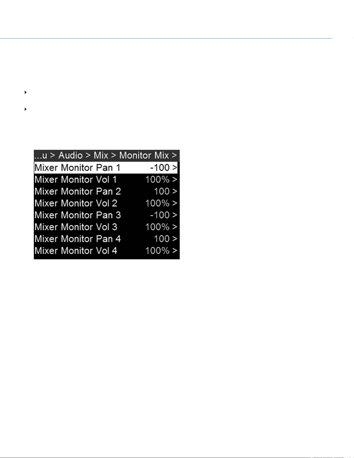
MONITOR MIX
The camera features a digital audio mixer that controls audio settings for external HD-SDI monitors that support audio. The
mixer controls volume and stereo settings. The mixer DOES NOT affect audio embedded in the R3D file. Monitor Mix offers
these settings:
Pan: Adjust the stereo mix for the channel. Range is –100 (Full Left) to 100 (Full Right). The default for Channel 1 and
Channel 3 is –100. The default for Channel 2 and Channel 4 is 100.
Volume: Adjust volume for the channel. Range is 0% to 100%. The default for each active channel is 100%. Channel 3 and
Channel 4 are active only when there is audio input.
SET UP PAN AND VOLUME
1. Go to Menu > Audio > Mix > Monitor Mix.
Figure: Monitor Mix Menu
COP YRIGHT © 2020 PA N A VISION IN TERN ATION AL, L.P . FW : V-1.0.0| 11 0
PANAVISION MILLENNIUM DXL2
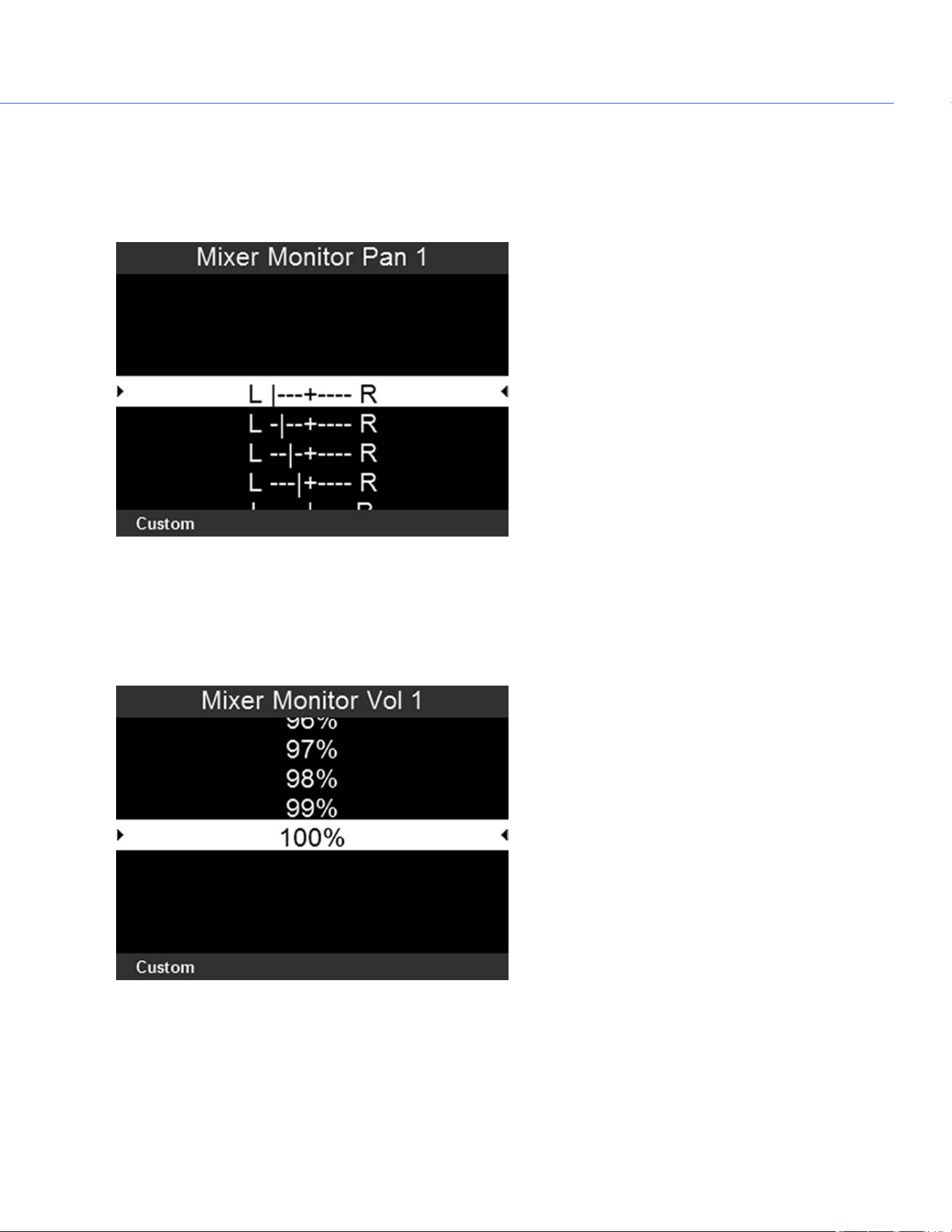
2. To set up a channel's stereo setting:
A. Select Mixer Monitor Pan for the channel you want to set up.
B. Use the Scroll Wheel to highlight the setting you want.
C. Press Enter.
Figure: Set Up Channel Stereo Setting
3. To set up a channel's volume:
A. Select Mixer Monitor Vol for the channel you want to set up.
B. Use the Scroll Wheel to highlight the setting you want.
C. Press Enter.
Figure: Set Up Channel Volume
COP YRIGHT © 2020 PA N A VISION IN TERN ATION AL, L.P . FW : V-1.0.0| 11 1
PANAVISION MILLENNIUM DXL2

AUDIO OUTPUT
The SDI ports output two (2) channels of 24-bit 48 KHz uncompressed, embedded digital audio. For information on how to set
up and mix the stereo channels, go to "Monitor Mix" on page110. To monitor audio via HD-SDI, the third-party monitor must
support audio.
AUDIO METER (VU METER)
The Audio Meter displays on the Audio Page. For more information, go to "Home Page Presets" on page76.
INCOMING AUDIO CHANNELS
When you select Input as the VU Meter Source, the Audio Meter displays the incoming audio channels (default). For more
information, go to "VU Meter" on page64. Channel 1 and Channel 2 are the default channels, correlating with the MIC-1 and
MIC-2 inputs on the camera. Channel 3 and Channel 4 are greyed out unless the camera detects audio input.
The channel names selected in the Audio menu determine the channel names displayed in the Audio Meter. For more
information, go to "Channel Sources and Names" on page107.
The Audio Meter shows the incoming audio signal when a source is selected, even if the channel is not recorded.
OUTGOING AUDIO
When you select Output as the VU Meter Source, the Audio Meter displays the Monitor Mix levels. For more information, go
to "VU Meter" on page64.
When recording to an external device, use the Output levels to help accurately monitor recorded audio.
COP YRIGHT © 2020 PA N A VISION IN TERN ATION AL, L.P . FW : V-1.0.0| 11 2
PANAVISION MILLENNIUM DXL2
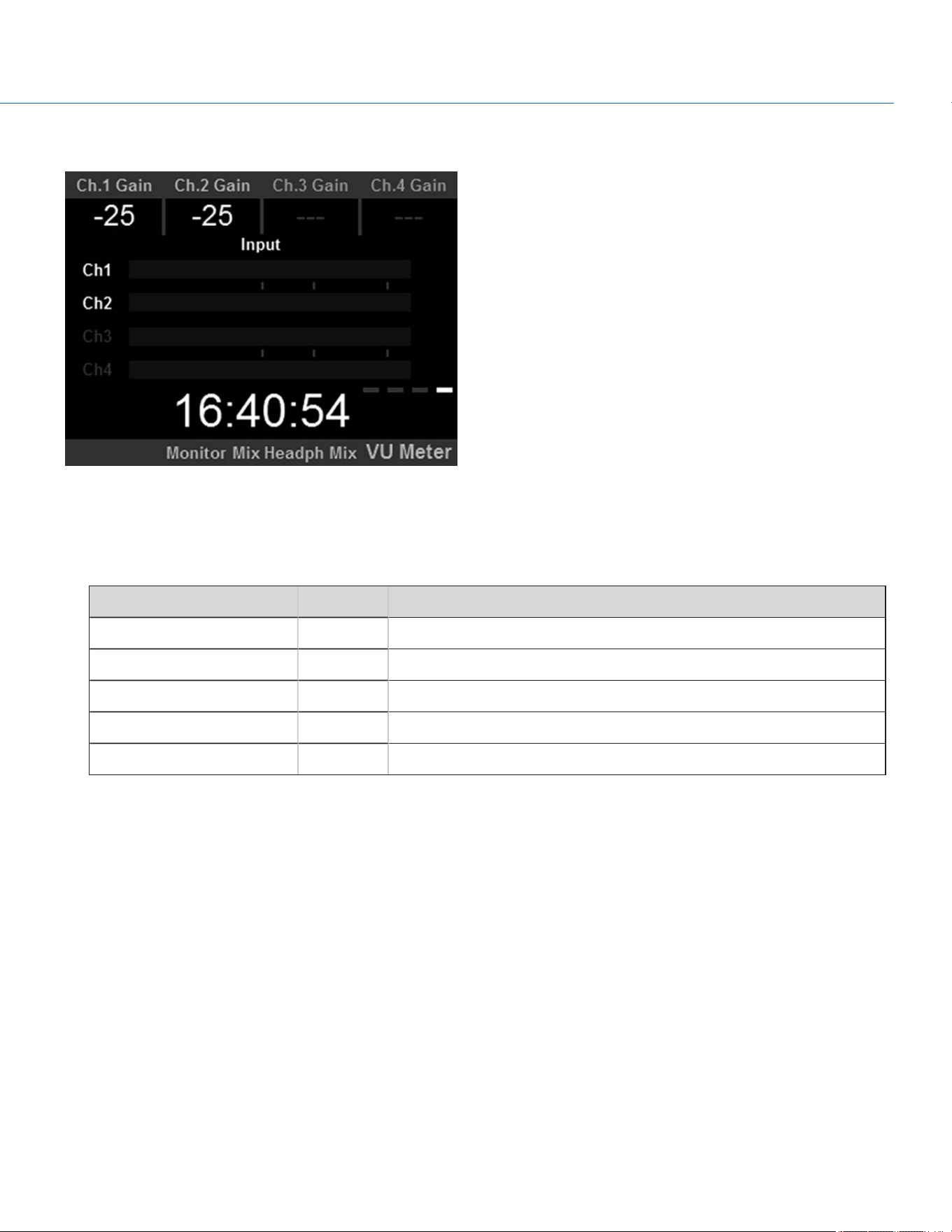
AUDIO METER LEVELS
Figure: Audio Meter
The camera updates the Audio Meter 12 times per second with the maximum signal from the last 1/12 of a second period.
The range of the Audio Meter is –52 dBFS to 0 dBFS.
The lines and colors indicate danger of clipping, as described in the table below:
LINE DBFS DESCRIPTION
First line (far left border) –52 dBFS Audio is not clipping
Second line –20 dBFS Audio is not clipping
Third line –12 dBFS Audio close to clipping
Fourth line –2 dBFS Audio is clipping
Fifth line (far right border) 0 dBFS Audio is clipping (if signal exceeds –1 dBFS, the whole bar is red)
NOTE: In the American broadcast and post production systems, –20 dBFS roughly corresponds to 0 VU and 4 dBu. In a digital
system, dBu is an approximation; the correct unit for digital audio levels is dBFS.
AUDIO DURING PLAYBACK
The camera plays all recorded channels during playback, and automatically unmutes any muted audio outputs.
COP YRIGHT © 2020 PA N A VISION IN TERN ATION AL, L.P . FW : V-1.0.0| 11 3
PANAVISION MILLENNIUM DXL2
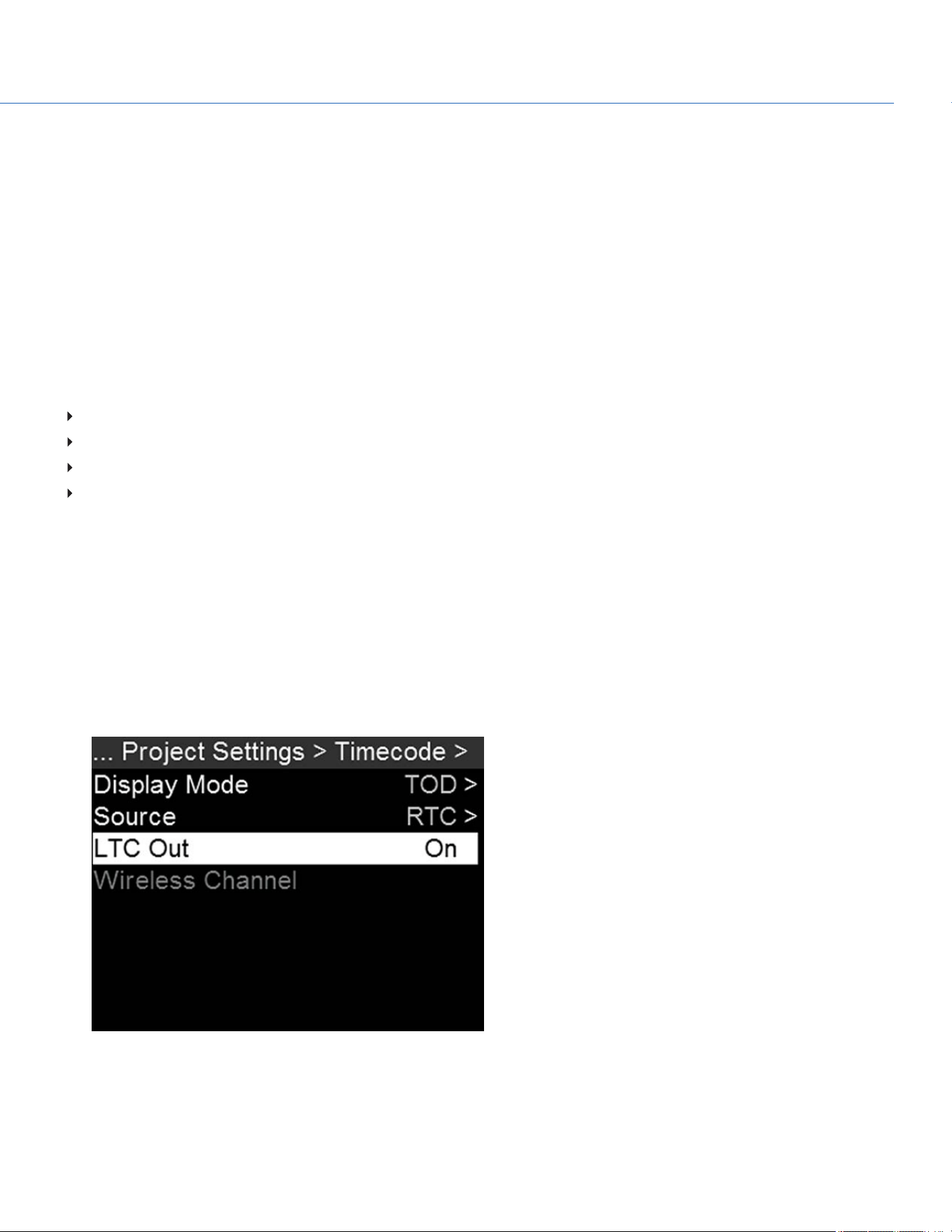
COP YRIGHT © 2020 PA N A VISION IN TERN ATION AL, L.P . FW : V-1.0.0| 114
PANAVISION MILLENNIUM DXL2
TIMECODE, GENLOCK, MULTI-CAMERA SETUP
This chapter describes timecode, genlock, and multi-camera operations such as 3D and array setup.
TIMECODE
Timecode is a numeric sequence based on SMPTE 12M that aids in the management and synchronization of footage and
audio. Timecode is embedded in recorded RAW files, QuickTime
®
files (if recording an Apple
®
ProRes codec), and MXF files
(if recording an Avid
®
codec) as metadata and in HANC metadata provided by the HD-SDI monitor output. The camera can
generate timecode on its own or can receive and sync to timecode generated by an external source.
Timecode displays on the side UI panels, SDI overlays and is embedded as metadata. Timecode is represented as an eight (8)
digit sequence (HH:MM:SS:FF), where:
HH: Hours
MM: Minutes
SS: Seconds
FF: Frames
NOTE: Timecode is most accurate and effective when coupled with genlock. For more information, go to "Genlock" on
page116.
SET UP INTERNAL TIMECODE
To set up and adjust timecode generated by the camera, follow the instructions below:
1. Go to Menu > Project Settings > Timecode.
2. Select the desired Display Mode.
3. Set Source to RTC.
4. If applicable, enable LTC Out (Linear Timecode Out).
Figure: Set Up Internal Timecode
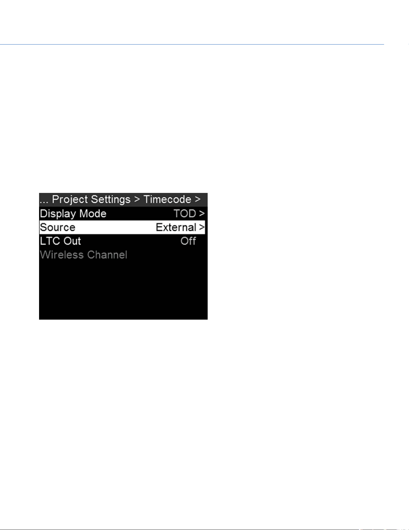
OUTPUT TIMECODE
The camera can output a timecode signal to an external device or to a slaved camera.
1. Follow the instructions in "Set Up Internal Timecode" on the previous page to set up internal timecode.
2. Use a cable to connect the TIMECODE port on the camera to another device.
INPUT EXTERNAL TIMECODE
To input timecode generated by an external device, follow the instructions below:
1. Use a cable to connect the TIMECODE port on the camera to another device.
2. Go to Menu > Project Settings > Timecode.
3. Select the desired Display Mode.
4. Set Source to External.
The TC indicator turns green when an external timecode source is locked.
Figure: Use External Timecode
SYNC TIMECODE WITH ACN
The camera can connect to the wireless Ambient communication and synchronization network (ACN™). To connect to ACN,
follow the instructions below:
1. Go to Menu > Project Settings > Timecode.
2. Set Source to ACN. For more information, go to "Timecode" on page55.
3. In the Timecode menu, set the Wireless Channel to the same wireless channel as the device. For more information, go to
"Wireless Channel" on page55.
COP YRIGHT © 2020 PA N A VISION IN TERN ATION AL, L.P . FW : V-1.0.0| 11 5
PANAVISION MILLENNIUM DXL2
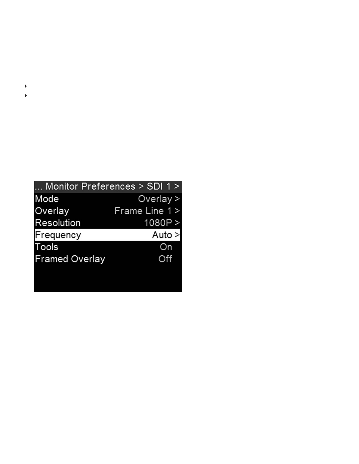
GENLOCK
Generator locking (genlock) is a tri-level signal used to synchronize video and audio systems. Genlock is based on SMPTE
296M and 274M. There are two (2) important genlock sync modes:
Monitor Sync
Sensor Sync
MONITOR SYNC
Monitor Sync occurs when an incoming genlock signal is compatible with the monitor output frequency. Monitor Sync is
achievable even if the camera is using another form of synchronization to sync the camera sensor.
1. Use a BNC cable to connect the GENLOCK port on the camera to genlock device.
2. Set up the frequency for the HD-SDI output (select Auto to automatically match the HD-SDI output to the current Project
Time Base). For more information, go to "Frequency" on page59.
Monitor Sync is achieved automatically when an incoming genlock signal is compatible with the monitor output
frequency. When Monitor Sync is achieved, the GEN indicator illuminates green.
Figure: Set Frequency for Monitor
COP YRIGHT © 2020 PA N A VISION IN TERN ATION AL, L.P . FW : V-1.0.0| 11 6
PANAVISION MILLENNIUM DXL2
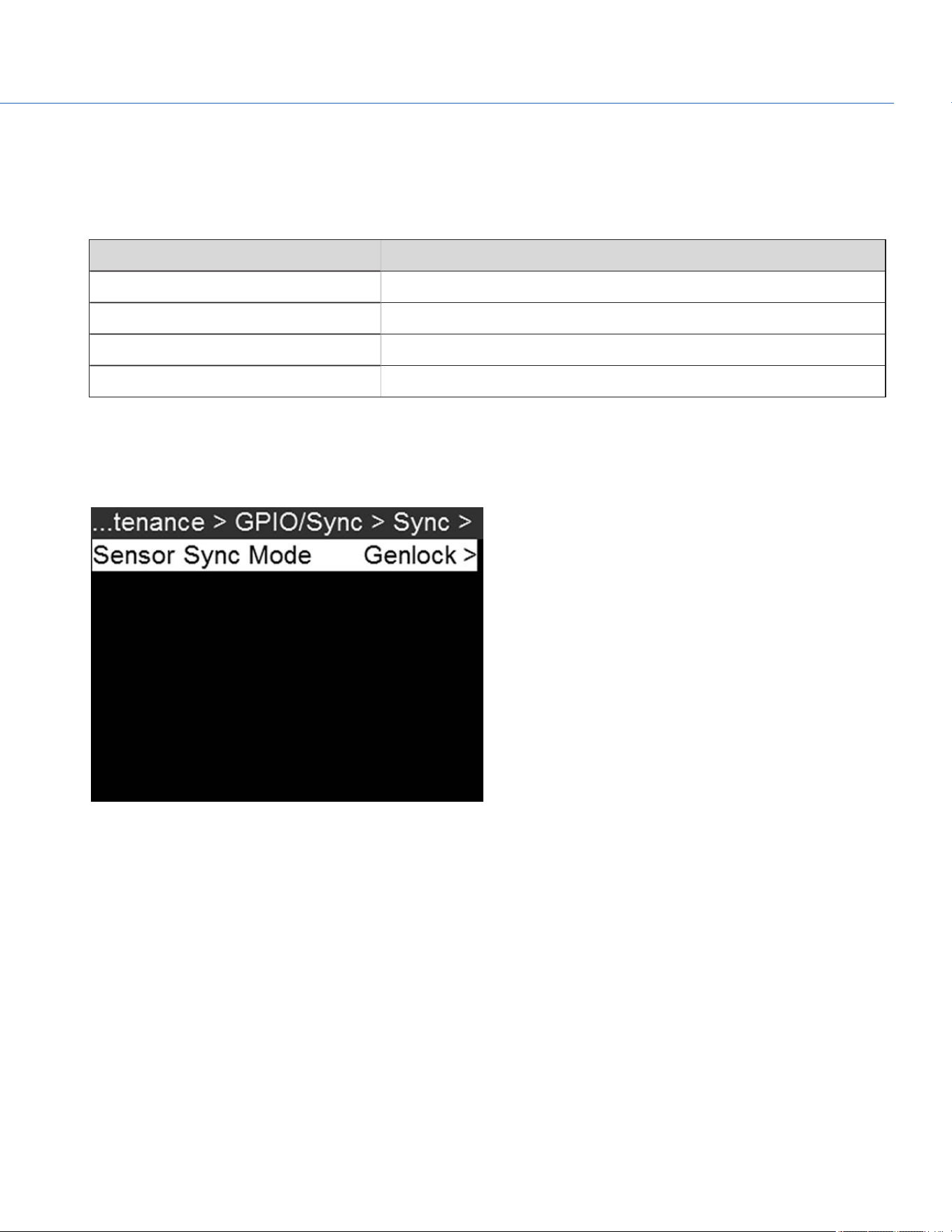
SENSOR SYNC
Sensor Sync is achieved when an incoming genlock signal is compatible with the monitor output frequency, project time base,
and recording frame rate. In Sensor Sync mode, sensor timing is locked to the genlock signal. Sensor Sync requires the
following synchronized settings:
SETTING MENU LOCATION PATH
Genlock signal frequency N/A; external genlock device
HD-SDI monitor output frequency Menu > Monitoring > Monitor Preferences > select monitor
Project Time Base Menu > Project Settings > Timebase
Recording Frame Rate FPS (from home page)
To set up and enable Sensor Sync Mode, follow the instructions below:
1. Use a BNC cable to connect the GENLOCK port on the camera to genlock device.
2. Go to Menu > Maintenance > GPIO/Sync > Sync.
3. Set Sensor Sync Mode to Genlock.
Figure: Set Sensor Sync Mode to Genlock
4. Set up the frequency for the HD-SDI output (select Auto to automatically match the HD-SDI output to the current Project
Time Base). For more information, go to "Frequency" on page59.
The GEN indicator turns green when a compatible genlock signal is present and genlock is enabled. The SYNC indicator
turns green when Sensor Sync is achieved.
COP YRIGHT © 2020 PA N A VISION IN TERN ATION AL, L.P . FW : V-1.0.0| 11 7
PANAVISION MILLENNIUM DXL2

MASTER/SLAVE OPERATION
NOTE: The Master camera controls metadata and basic camera parameters of the Slave cameras. Any other setting changes
required by the Slave cameras must be made before recording.
This section describes operation in Master/Slave configuration and clip naming conventions for clips recorded on those
cameras. Master/Slave is the most common configuration for Stereo/3D productions.
When cameras are operated in Master/Slave configuration, you can perform the following operations:
Power: Turn off the Master camera to turn off both cameras.
Record: Press the PWR/REC key on the Master camera to start/stop recording on both cameras.
Change settings: Change settings on the Master camera to change settings on the Slave camera.
For a Master/Slave configuration to function, the cameras must have the same:
Firmware version
Project time base
Recording frame rate
Sensor
COP YRIGHT © 2020 PA N A VISION IN TERN ATION AL, L.P . FW : V-1.0.0| 11 8
PANAVISION MILLENNIUM DXL2
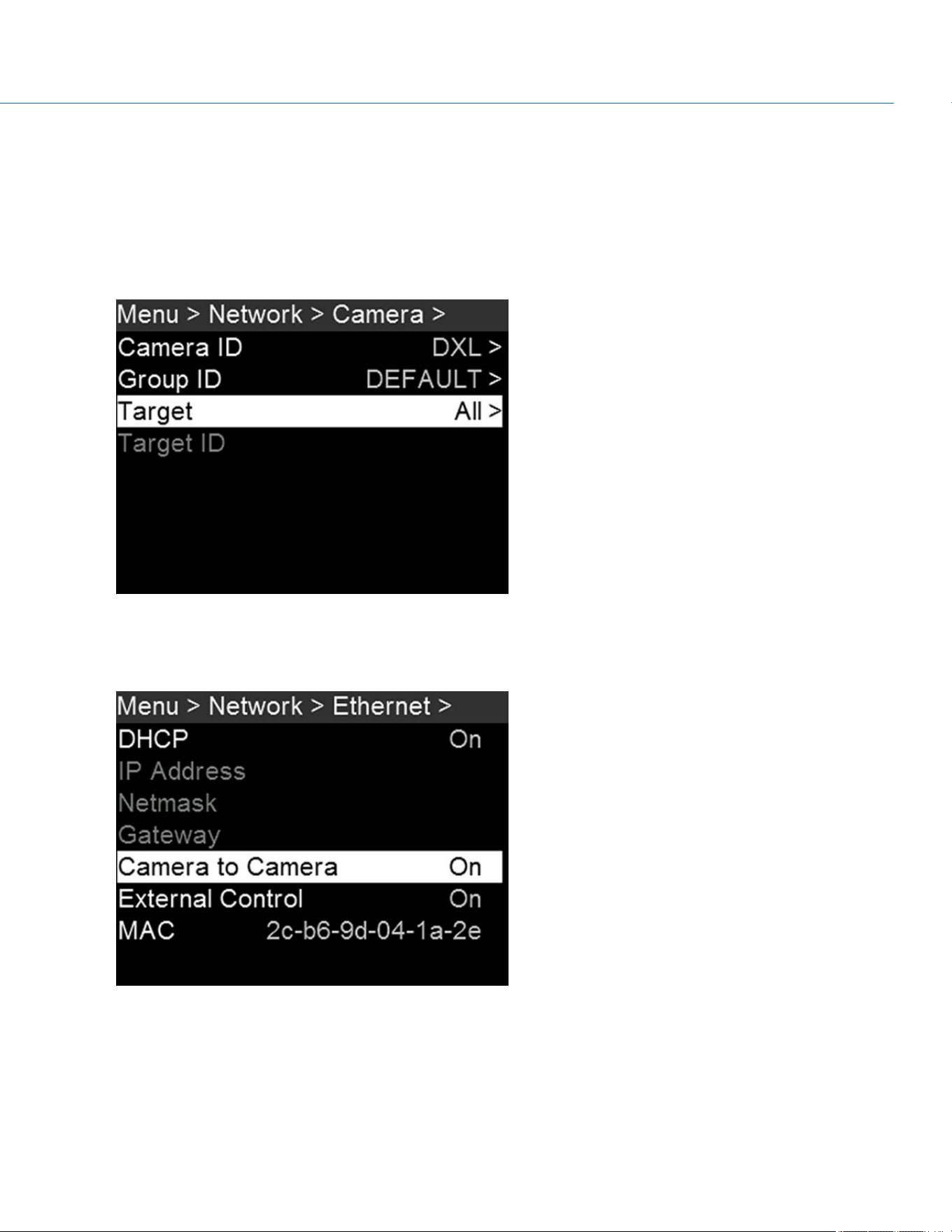
SET UP MASTER/SLAVE OPERATION
1. Use a Gig-E cable to connect the GIG-E port on one camera to the GIG-E port on the other camera.
2. On the Master camera, follow the instructions below:
A. Go to Menu > Network > Camera.
B. Type a name for the camera (Example: CAM A, LEFT, MASTER, etc) in the Camera ID field.
C. Set Target to All.
Figure: Set Target to All
D. Go to Menu > Network > Ethernet.
E. Enable Camera to Camera.
Figure: Set Target to All
COP YRIGHT © 2020 PA N A VISION IN TERN ATION AL, L.P . FW : V-1.0.0| 11 9
PANAVISION MILLENNIUM DXL2
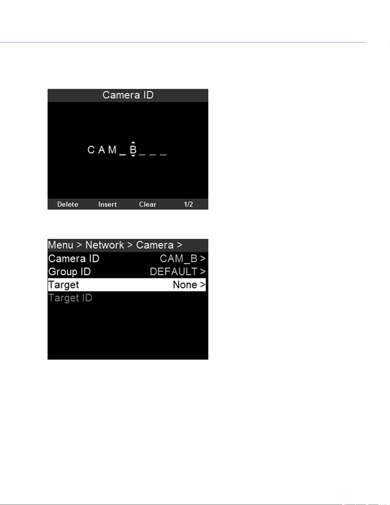
3. On the Slave camera(s), follow the instructions below:
A. Go to Menu > Network > Camera.
B. Type a name for the camera (Example: CAM B, RIGHT, SLAVE, etc) in the Camera ID field.
Figure: Set Target to All
C. Set Target to None.
Figure: Set Target to All
D. Go to Menu > Network > Ethernet.
COP YRIGHT © 2020 PA N A VISION IN TERN ATION AL, L.P . FW : V-1.0.0| 120
PANAVISION MILLENNIUM DXL2
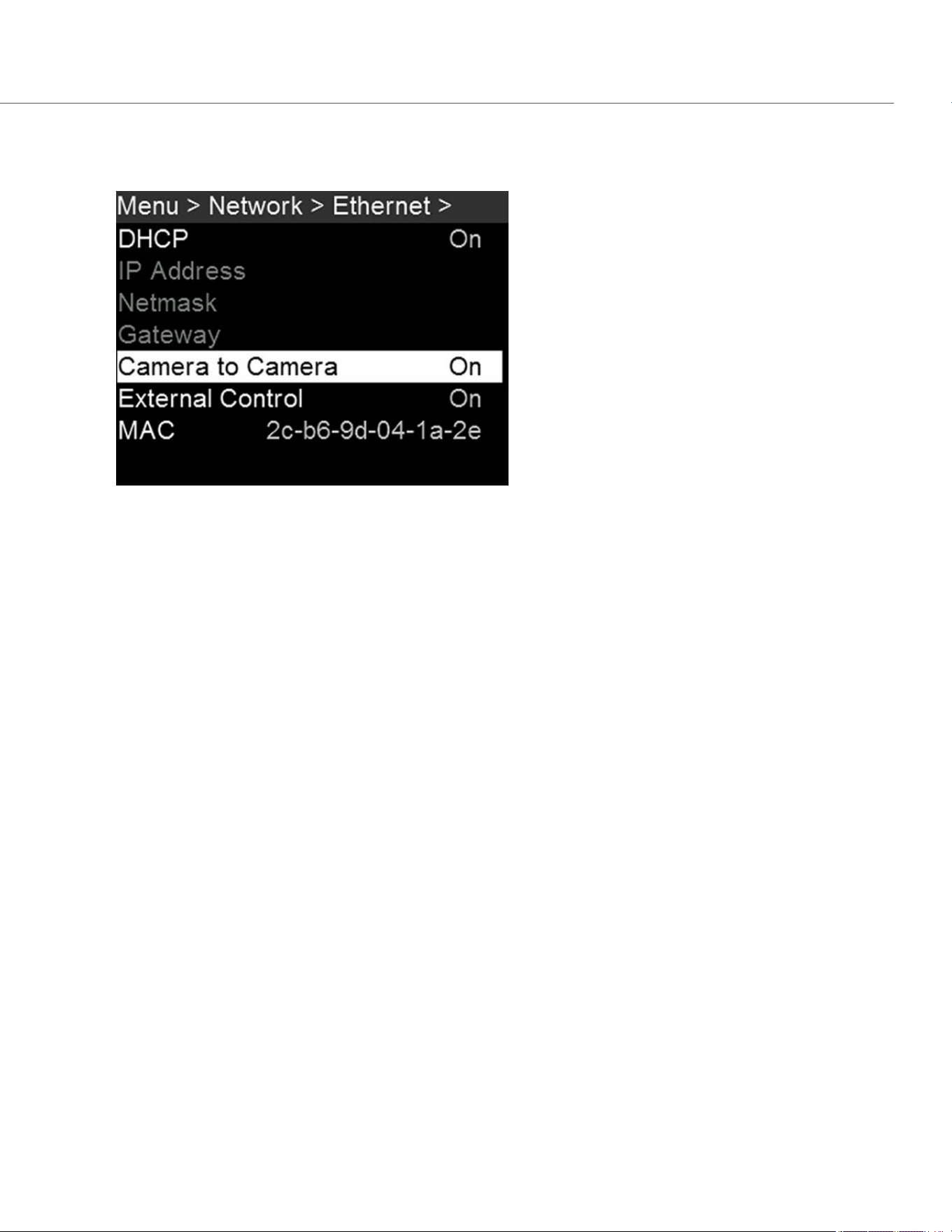
E. Enable Camera to Camera.
The LANindicator illuminates green.
Figure: Set Target to All
NOTE: Cameras can also be set up in a Master/Master configuration. To set up Master/Master, set Target to All on both
cameras, allowing either camera to make changes and control record start/stop.
SET REEL NUMBER, CAMERA ID, AND CAMERA POSITION
NOTE: Camera ID and Camera Position settings can also be found at Menu > Project Settings > Slate.
To prepare media and slate settings for a Master/Slave or Stereo/3D production, follow the instructions below:
1. On both Master and Slave cameras, go to Menu > Media > Quick Format or Full Format.
2. On both Master and Slave cameras, select the desired Reel Number and Camera ID settings. The Reel Number and
Camera ID settings on both cameras should match.
3. On the Master camera, change the Camera Position to Left, representing “left eye”.
4. On the Slave camera, change the Camera Position to Right, representing “right eye”.
5. On both cameras, select Format Media to format media and set the Reel Number, Camera ID, and Camera Position
settings.
COP YRIGHT © 2020 PA N A VISION IN TERN ATION AL, L.P . FW : V-1.0.0| 121
PANAVISION MILLENNIUM DXL2
MULTI-CAMERA CLIP NAMING CONVENTIONS
This section describes automatic camera-generated clip naming conventions based on slate settings. Cameras use the Reel
No, Cam ID, and Cam Pos settings to generate a custom clip name.
For example, if you have two (2) cameras in Master/Slave configuration and format media on both cameras with the
following settings:
CAMERA REEL NUMBER CAMERA ID CAMERA POSITION
Master 1 S Left
Slave 1 S Right
The first clip recorded by this Master/Slave camera configuration is:
Master: S001_L001_0503B6.R3D
Slave: S001_R001_0503R7.R3D
NOTE: B6 and R7 are examples of camera-generated wildcard characters.
NOTE: If both cameras are assigned the same Camera Position—Left, Center, or Right—the recorded clips will have the same
filename structure, with the exception of the camera-generated wildcard characters. For example:
Master: A001_C001_0503B6.R3D
Slave: A001_C001_0503R7.R3D
NOTE: Reel Number, Camera ID, and Camera Position can be set when formatting media.
SET UP STEREO/3D CONFIGURATION
This section describes basic procedures for connecting two (2) cameras in a Master/Slave configuration for 3D operation.
NOTE: When providing the signals to a Stereo Image Processor (SiP) for verifying 3D alignment, set the HD-SDI monitor
output on both cameras to have the same overlay configuration.
NOTE: For genlock to function correctly, the cameras must be on the same firmware version, and must be using the same
project time base and recording frame rate.
To set up a Stereo/3D setup, follow the instructions below.
1. On both cameras, set the project time base and recording frame rate.
2. On both cameras, follow the instructions in "Sensor Sync" on page117 to achieve Sensor Sync genlock status.
The GEN and SYNC indicators in the Lower Status Row illuminate green.
3. Follow the instructions in "Set Up Master/Slave Operation" on page119 to set Master and Slave camera settings.
4. On both cameras, follow the instructions in "Set Reel Number, Camera ID, and Camera Position" on the previous page to
set up media and camera settings.
COP YRIGHT © 2020 PA N A VISION IN TERN ATION AL, L.P . FW : V-1.0.0| 122
PANAVISION MILLENNIUM DXL2

CAMERA ARRAY
SET UP A CAMERA ARRAY
NOTE: For genlock to function correctly, the cameras must be on the same firmware version, and must be using the same
project time base and recording frame rate.
You can sync more than two (2) cameras for applications and productions that require a camera array. To set up a camera
array, you need a 1000Base-T gigabit Ethernet router.
To set up a camera array, follow the instructions below:
1. On each camera, go to Menu > Network > Camera and set the following:
A. Set Target to All.
B. Enter a matching name in the Group ID field. All cameras must have the same Group ID name.
2. On each camera, go to Menu > Network > Ethernet, and set the DHCP, Camera to Camera, and External Control options
to On.
3. Follow the instructions in "Sensor Sync" on page117 to connect each camera to the genlock device.
The GEN and SYNC indicators in the Lower Status Row illuminate green.
4. Follow the instructions in "Set Up Master/Slave Operation" on page119 to set Master and Slave camera settings. Instead
of using the Master/Slave Gig-E Cable, connect each camera to the router.
5. On each camera, follow the instructions in "Set Reel Number, Camera ID, and Camera Position" on page121 to prepare
media and camera settings.
COMPATIBLE TIMECODE DEVICES
The Panavision Millennium DXL2 is compatible with all Ambient timecode devices, as well as the following devices from other
manufacturers. Additional timecode devices may be compatible, but have not yet been tested.
Denecke SB-3 Syncbox Time-Code Generator
Sound Devices 788T
Sound Devices 744
Sound Devices PIX-240
Zaxcom Nomad 12
Zaxcom ZFR100
Zaxcom ZFR200
COP YRIGHT © 2020 PA N A VISION IN TERN ATION AL, L.P . FW : V-1.0.0| 123
PANAVISION MILLENNIUM DXL2

COMPATIBLE GENLOCK DEVICES
The following genlock devices are compatible with the camera. Additional genlock devices may be compatible, but have not
yet been tested.
AJA
®
GEN10 HD/SD/AES Sync Generator with Universal Power Supply
Ambient ACL 202CT
Ambient ACL 203
Ambient ACL 204
Denecke SB-T
Evertz Master Clock 5600MSC
NOTE: Ensure that your genlock device provides a full-strength genlock signal to each camera. Splitting a genlock signal
weakens it, which may compromise the sync between cameras.
COP YRIGHT © 2020 PA N A VISION IN TERN ATION AL, L.P . FW : V-1.0.0| 124
PANAVISION MILLENNIUM DXL2

COP YRIGHT © 2020 PA N A VISION IN TERN ATION AL, L.P . FW : V-1.0.0| 125
PANAVISION MILLENNIUM DXL2
UPGRADE CAMERA FIRMWARE
VERIFY CURRENT CAMERA FIRMWARE
To see the firmware version that is currently installed on your camera, go to Menu > Maintenance > System Status >
Camera Info. A higher number reflects a later release.
UPGRADE CAMERA FIRMWARE
Install the most recent firmware. Unless otherwise specified in the release notes, you do not need to upgrade to any firmware
in between your current version and the most recent version available online.
1. Connect a Panavision MINI-MAG SSD to your computer.
2. Unzip the firmware zip file.
3. Copy the force_upgrade folder and its contents to the top level of the SSD directory.
4. Eject or unmount the SSD, and then remove the SSD.
5. Ensure that the camera is turned off.
6. Insert the SSD with the force_upgrade folder into your camera.
7. Turn on the camera.
The upgrade runs automatically.
During upgrade, the fans run at high speed and the PWR and REC LEDs flash green. After approximately 15 seconds, the
LEDs stop flashing and the camera turns off. Nothing displays on the external monitors during the upgrade.
8. After the camera turns off, remove the SSD and wait 10 seconds.
9. Turn on the camera.
The camera may take 30 seconds or longer to upgrade all of the attached modules. During this time the PWR and REC
LEDs flash green and nothing displays on the external monitors.
10. Verify that the firmware version listed matches the firmware version that you downloaded. For more information, go to
"Verify Current Camera Firmware" above.
11. Reformat the SSD before recording.

COP YRIGHT © 2020 PA N A VISION IN TERN ATION AL, L.P . FW : V-1.0.0| 126
PANAVISION MILLENNIUM DXL2
CAMERA SYSTEM MAINTENANCE
All Panavision products are designed for rugged durability, but precision instruments demand proper care. Follow the
instructions in this chapter to clean, maintain, and store your devices.
WARNING: DO NOT rinse or immerse the camera or other accessories in water. Keep dry at all times.
WARNING: DO NOT use soaps, detergents, ammonia, acetone, alkaline cleaners, abrasive cleaning compounds, or solvents.
These substances may damage lens coatings and electronic circuitry.
WARNING: DO NOT use an excess of cleaning solution.
WARNING: DO NOT reuse swabs or wipes.
WARNING: DO NOT attempt to clean the sensor or optical cavity for any reason.
WARNING: DO NOT attempt to modify, dismantle, or open the camera, lens, or other accessory as doing so may expose you
to electric shock and serious injury. There are no user-serviceable parts inside. Alteration or repairs made to the camera, lens,
or other accessory, except by a Panavision authorized service facility, voids all warranties.
WARNING: DO NOT use compressed air and gas dusters on the sensor or on any optics.
CAMERA BODY AND ACCESSORY EXTERIOR SURFACES
Use a filtered, non-residue gas duster to clean non-critical areas, such as around the fans and other recesses on the
exterior of the camera.
Clean with a dry lint-free cloth. When cleaning your camera and accessories, remember that the devices are not
waterproof and moisture can damage electronic circuitry.
BRAIN AND ACCESSORY STORAGE
WARNING: DO NOT store the camera or accessories in any place with extreme temperatures, direct sunlight, high humidity,
severe vibration, or strong magnetic fields.
WATER DAMAGE
WARNING: DO NOT attempt to power any device that may have water damage.
WARNING: DO NOT place the device in a container of rice, silica gel, or desiccant packets in an attempt to dry the device.

COP YRIGHT © 2020 PA N A VISION IN TERN ATION AL, L.P . FW : V-1.0.0| 127
PANAVISION MILLENNIUM DXL2
TROUBLESHOOT YOUR CAMERA
GENERAL TROUBLESHOOTING
FIRMWARE DOES NOT UPGRADE
SYMPTOM
During an attempt to upgrade firmware, the PWR and REC LEDs flash red.
After an attempt to upgrade firmware, the firmware version does not change.
POTENTIAL RESOLUTIONS
After downloading the firmware upgrade file, ensure that you unzip the file before saving it to the SSD.
Ensure that the “force_upgrade” folder is saved to the top level of the SSD, and not to a subfolder.
GENERAL: MODULE OR LENS MOUNT NOT FUNCTIONING
SYMPTOM
A module or lens mount is not functioning correctly, or is not communicating with the camera.
POTENTIAL RESOLUTIONS
Upgrade your camera firmware. For more information, go to "Upgrade Camera Firmware" on page125.
Reset your camera’s default settings. For more information, go to "Reset Defaults" on page101.
SCREEN FREEZES OR DOES NOT DISPLAY
SYMPTOM
The screen freezes or does not display.
POTENTIAL RESOLUTION
Perform a Hard Restore. For more information, go to "Perform a Hard Restore" on the next page.
LCD FLICKER
SYMPTOM
The LCD or monitor is flickering.
POTENTIAL RESOLUTIONS
Set the LCD frequency to 60 Hz. For more information, go to "Frequency" on page59.
Use a different cable.
Ensure cables are properly attached.

LCD BLANK AT STARTUP
SYMPTOM
When you turn on the camera, the LCD does not show any image.
POTENTIAL RESOLUTIONS
Turn off the camera. Wait at least three (3) seconds, and then turn the camera back on.
CAMERA DOES NOT TURN ON
SYMPTOM
The camera does not turn on (does not boot up), even when powered.
POTENTIAL RESOLUTIONS
Remove all accessories and power the camera using the power adaptor.
Perform a Hard Restore. For more information, go to "Perform a Hard Restore" below.
If the camera does not turn on when a battery is attached, but does turn on when DC power is attached, toggle the Auto
Boot on Power switch to Off (identified by a black star).
PERFORM A HARD RESTORE
A common way to resolve camera firmware issues is to perform a Hard Restore. A Hard Restore functions like a System
Restore in that it changes all settings to the factory default values.
To perform a Hard Restore, follow the instructions below:
1. With the camera turned off, hold the PWR/REC key on the camera for 20 seconds or until the fans turn at a high speed.
2. Release the PWR/REC key.
The screen displays correctly.
NOTE: User key settings reset as well as any other changes from the default settings.
IMAGE APPEARS GRAINY
SYMPTOM
Image or footage appears grainy.
POTENTIAL RESOLUTIONS
Calibrate the sensor before recording additional clips. For more information, go to "Sensor Calibration" on page94.
Check the histogram to ensure proper exposure. Noise occurs if an image is overexposed or underexposed.
Use the lowest REDCODE
®
compression possible for the settings you have selected.
Use a higher resolution.
Use Adaptive fan mode to regulate the camera temperature. Noise occurs when the temperature from the applied
calibration map is not in sync.
COP YRIGHT © 2020 PA N A VISION IN TERN ATION AL, L.P . FW : V-1.0.0| 128
PANAVISION MILLENNIUM DXL2

BLACK AND WHITE IMAGE
SYMPTOM
The display shows that an image is in black and white, and the menus are still in color.
POTENTIAL RESOLUTIONS
Check the Color Saturation setting. If the Saturation setting is set to a low value, change the Saturation to a higher value.
Reset your camera’s default settings. For more information, go to "Reset Defaults" on page101.
INCORRECT COLOR TEMPERATURE
SYMPTOM
The camera color temperature is off and the image looks warmer or cooler than normal.
POTENTIAL RESOLUTIONS
Perform an auto white-balance. For more information, go to "" on page37.
Calibrate the sensor. For more information, go to "Sensor Calibration" on page94.
TIMECODE OR GENLOCK DOES NOT FUNCTION
SYMPTOM
The SYNC, GEN, and/or TC light is red, yellow, or greyed out.
POTENTIAL RESOLUTIONS
Ensure that your timecode or genlock device is compatible. For more information, go to "Compatible Timecode Devices"
on page123 and "Compatible Genlock Devices" on page124.
Use a different cable.
Ensure that your timecode or genlock device settings match your project settings.
Ensure that your timecode or genlock device is set to the correct source. For more information, go to "Timecode" on
page114 and "Genlock" on page116.
Ensure that your Sensor Sync Mode is set to Genlock. For more information, go to "Sensor Sync" on page117.
Set the ACN (Ambient Clockit Network) to Off.
COP YRIGHT © 2020 PA N A VISION IN TERN ATION AL, L.P . FW : V-1.0.0| 129
PANAVISION MILLENNIUM DXL2

POSSIBLE HOT PIXEL
SYMPTOM
Your camera displays a possible hot pixel.
EXPLANATION
There may not be an issue with the pixel itself. The sensor can display a hot pixel when the sensor calibration is outdated.
Current camera settings and temperature can affect pixel calibration.
POTENTIAL RESOLUTIONS
Calibrate the sensor. For more information, go to "Sensor Calibration" on page94.
Upgrade your camera firmware. For more information, go to "Upgrade Camera Firmware" on page125.
Reset your camera’s default settings. For more information, go to "Reset Defaults" on page101.
Check your footage on a computer to confirm that the hot pixel is from the camera sensor, not your display monitor.
If you determine that the camera sensor has a hot pixel, use REDCINE-X PRO to remove the hot pixel until the issue gets
resolved. For more information, see the REDCINE-X PRO Operation Guide, available at www.red.com/downloads.
COP YRIGHT © 2020 PA N A VISION IN TERN ATION AL, L.P . FW : V-1.0.0| 130
PANAVISION MILLENNIUM DXL2

ERROR MESSAGES
"UPGRADE ATTACHED PERIPHERALS" MESSAGE
SYMPTOM
During an attempt to upgrade firmware, the display shows the message “Upgrade Attached Peripherals”. After turning the
camera off and then on, the same message displays, and then prompts you to turn off the camera.
POTENTIAL RESOLUTION
Ensure that you are upgrading your camera to the newest firmware version.
One (1) of your modules or lens mounts (collectively known as “peripherals”) may be experiencing issues. Remove all
peripherals (except for the media bay), and upgrade firmware. Then attach another peripheral, and upgrade firmware
again. Repeat this process, upgrading one (1) peripheral at a time. This will identify which peripheral is experiencing issues.
PRESET COULD NOT BE APPLIED
SYMPTOM
The display shows the following message: “Preset Could Not Be Applied”.
POTENTIAL RESOLUTION
Turn off the camera, power it back up, and attempt to apply the preset that failed.
COP YRIGHT © 2020 PA N A VISION IN TERN ATION AL, L.P . FW : V-1.0.0| 131
PANAVISION MILLENNIUM DXL2

COP YRIGHT © 2020 PA N A VISION IN TERN ATION AL, L.P . FW : V-1.0.0| 132
PANAVISION MILLENNIUM DXL2
APPENDIX A:
TECHNICAL SPECIFICATIONS
PANAVISION MILLENNIUM DXL2
PANAVISION MILLENNIUM DXL2
SPECIFICATION DESCRIPTION
Sensor Type 16-bit, 35.5 Megapixel CMOS
Resolution 8192 x 4320
Sensor Size Large Format: 40.96mm x 21.60mm (Diagonal: 46.31mm)
Dynamic Range 16 stops
Max Frame
Rates
60 fps at 8K Full Frame (8192 x 4320)
75 fps at 8K 2.4:1 (8192 x 3456)
Recording Codec 8K RAW with simultaneous 4K proxy (ProRes or DNx)
Recording Media SSD (up to 1 hour on a single magazine)
File Type .r3d (supported in RED SDK)
Color Profile Light Iron Color 2 (compatible with all popular gamuts and transfer curves, including RAW, ACES,
selectable)
Weight 10 lbs.
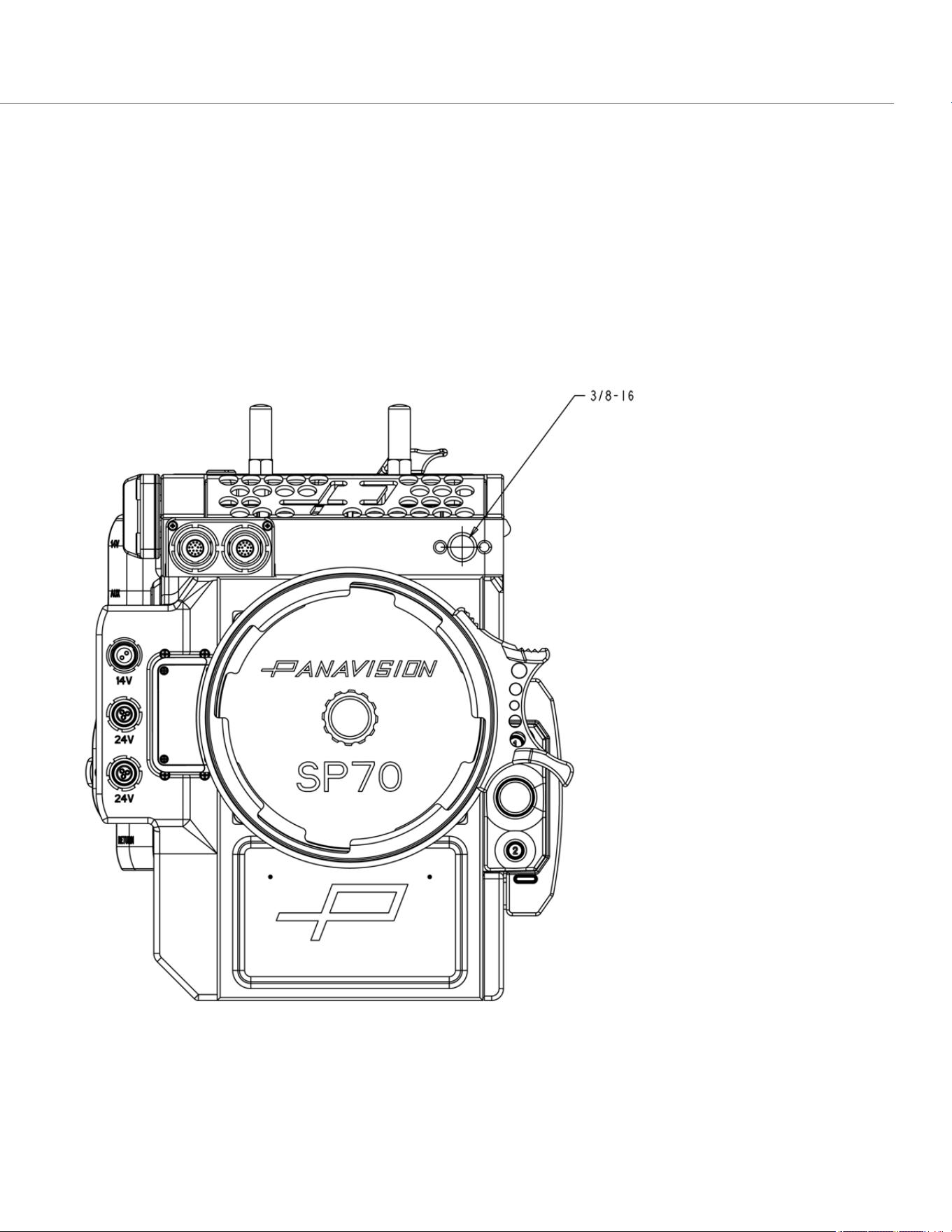
COP YRIGHT © 2020 PA N A VISION IN TERN ATION AL, L.P . FW : V-1.0.0| 133
PANAVISION MILLENNIUM DXL2
APPENDIX B: MECHANICAL
DRAWINGS
NOTE: Dimensions are shown in mm.
FRONT VIEW
Figure: Panavision Millennium DXL2 Front View
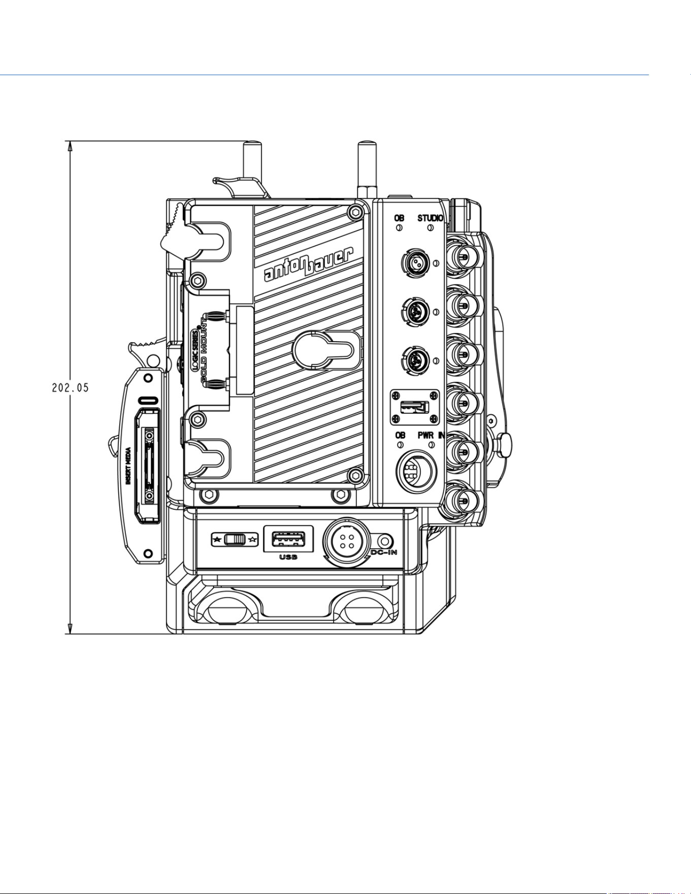
BACK VIEW
Figure: Panavision Millennium DXL2 Back View
COP YRIGHT © 2020 PA N A VISION IN TERN ATION AL, L.P . FW : V-1.0.0| 134
PANAVISION MILLENNIUM DXL2
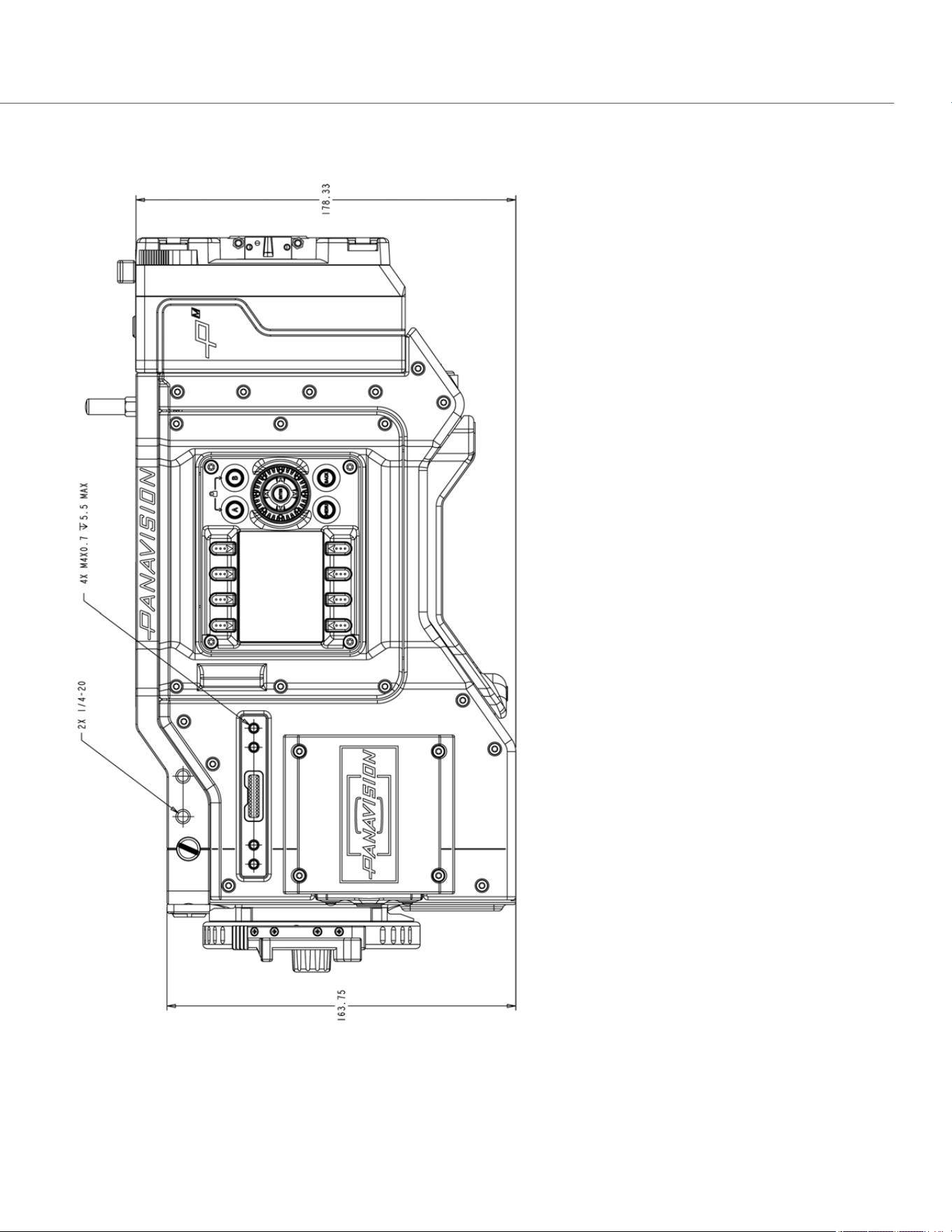
SIDE VIEW (RIGHT)
Figure: Panavision Millennium DXL2 Side View (Right)
COP YRIGHT © 2020 PA N A VISION IN TERN ATION AL, L.P . FW : V-1.0.0| 135
PANAVISION MILLENNIUM DXL2
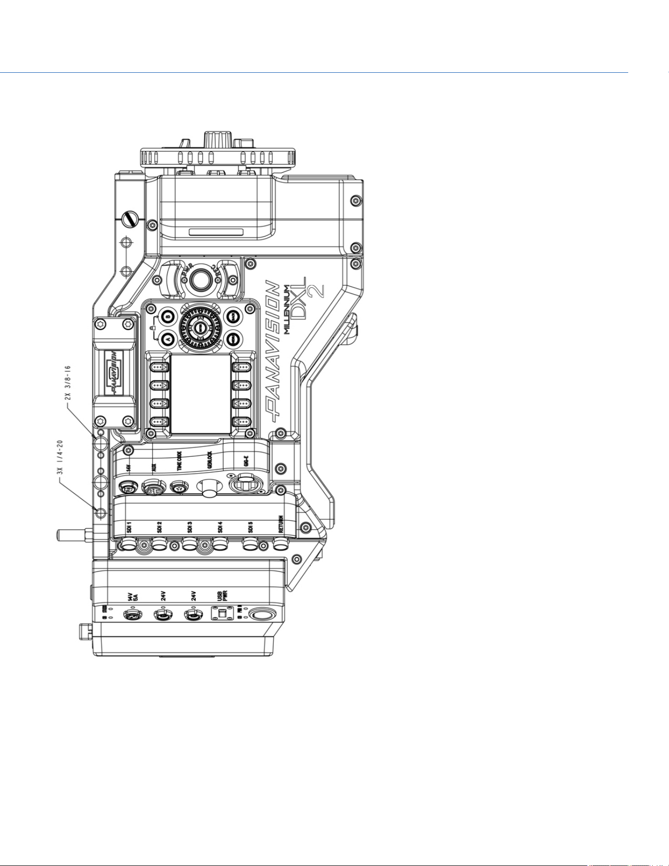
SIDE VIEW (LEFT)
Figure: Panavision Millennium DXL2 Side View (Left)
COP YRIGHT © 2020 PA N A VISION IN TERN ATION AL, L.P . FW : V-1.0.0| 136
PANAVISION MILLENNIUM DXL2
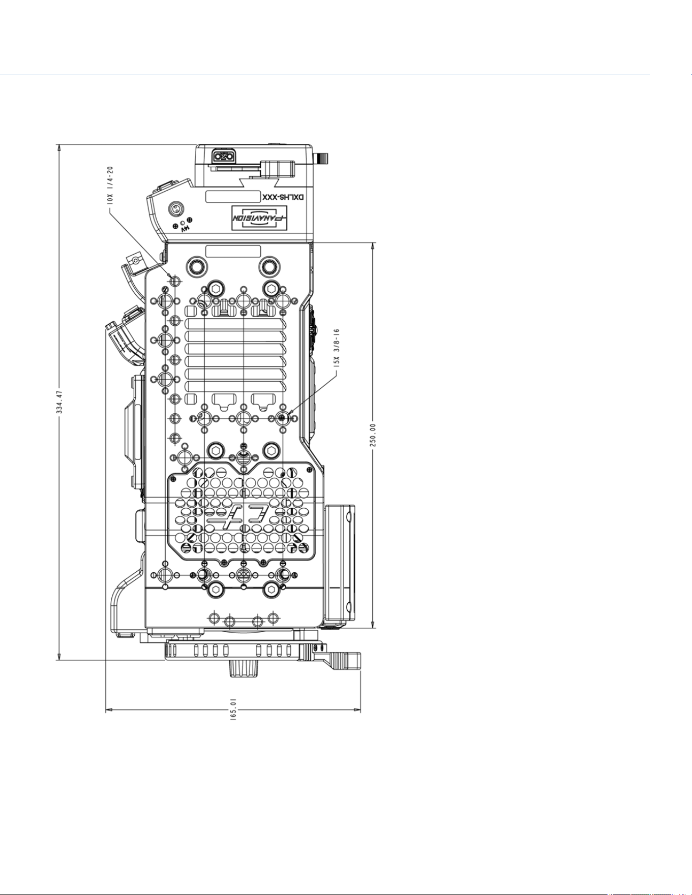
TOP VIEW
Figure: Panavision Millennium DXL2 Top View
COP YRIGHT © 2020 PA N A VISION IN TERN ATION AL, L.P . FW : V-1.0.0| 137
PANAVISION MILLENNIUM DXL2
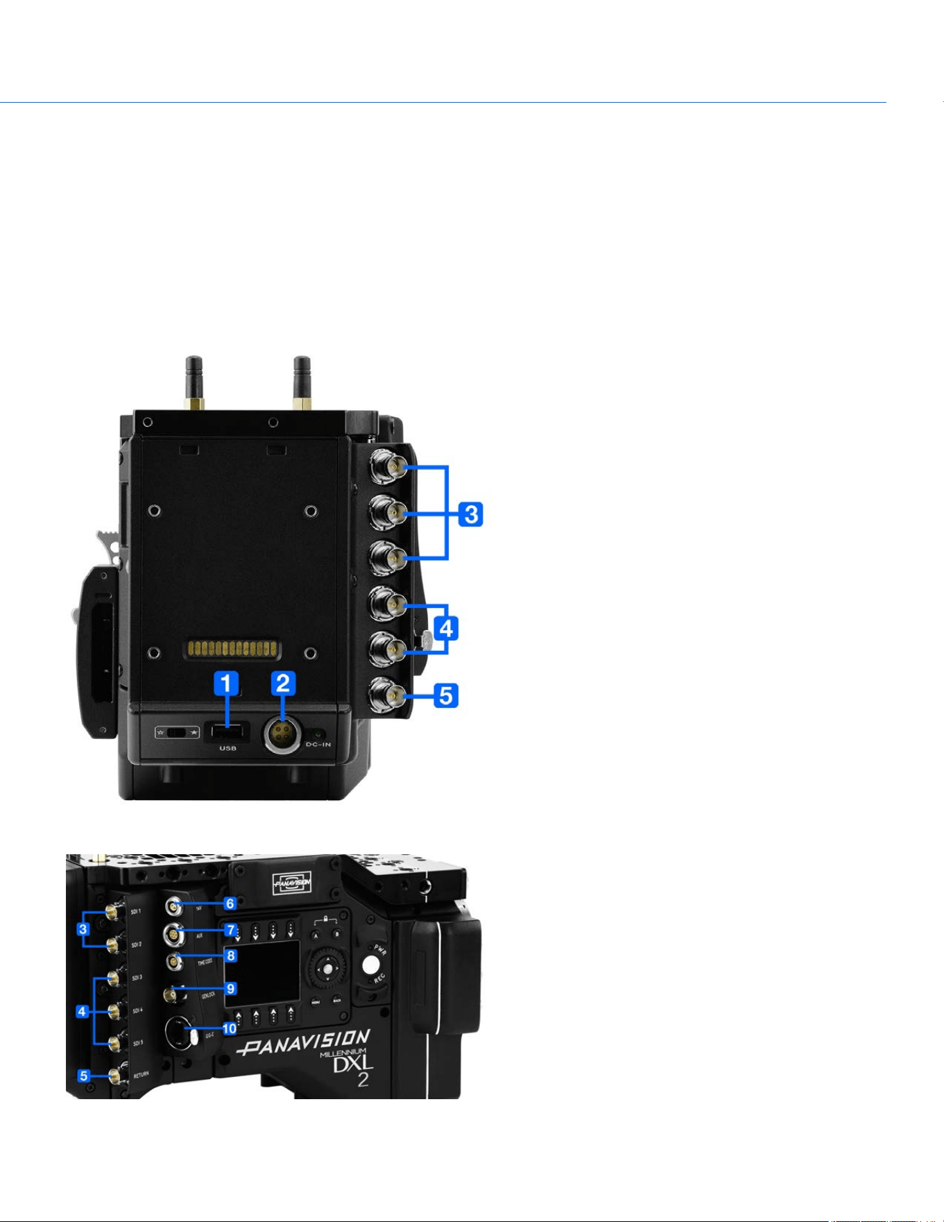
COP YRIGHT © 2020 PA N A VISION IN TERN ATION AL, L.P . FW : V-1.0.0| 138
PANAVISION MILLENNIUM DXL2
APPENDIX C: INPUT/OUTPUT
CONNECTORS
This appendix provides pinout information for the input/output connectors on the camera.
NOTE: When connecting a cable to a connector, align the key and red marker on the cable connector with the corresponding
key and marker on the device connection.
NOTE: Connector diagram images are for reference only. Diagrams are not to scale.
Figure: Panavision Millennium DXL2 Connectors
Figure: Panavision Millennium DXL2 Connectors
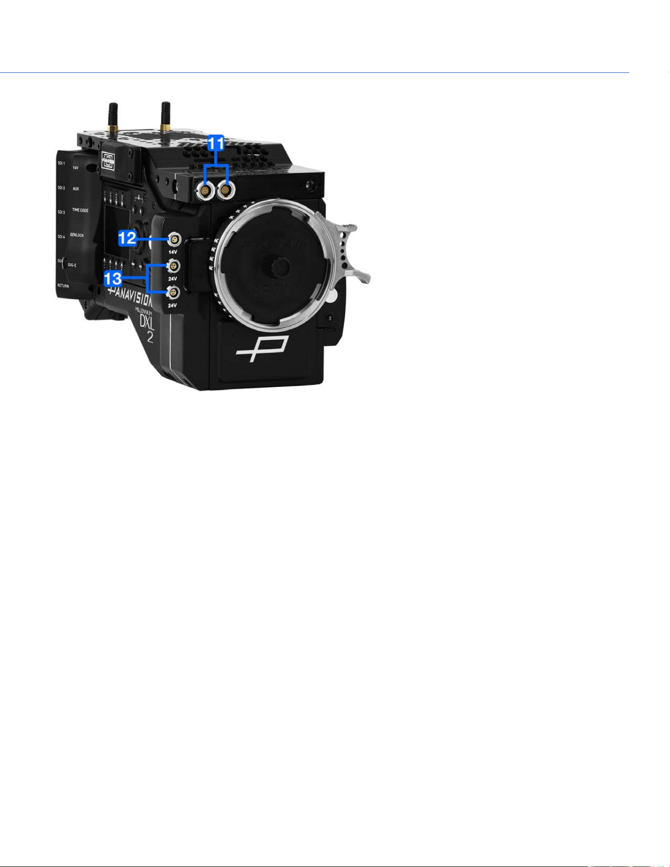
Figure: Panavision Millennium DXL2 Connectors
COP YRIGHT © 2020 PA N A VISION IN TERN ATION AL, L.P . FW : V-1.0.0| 139
PANAVISION MILLENNIUM DXL2

# CONNECTOR
NAME
MODULE DESCRIPTION CONNECTOR TYPE DETAILS
1 USB Camera USBpower out USB 2.0, Type A (power
only)
"USB Power" on the next
page
2 DC-IN Camera Power in 4-pin 2B LEMO "DC-IN" on the next page
3 SDI 1
SDI 2
SDI 3
SDI Module 3G HD-SDI BNC
"3G HD-SDI" on page143
4 SDI 4
SDI 5
SDI Module 6G/3G HD-SDI BNC "6G/3G HD- SDI" on
page142
5
RETURN SDI Module 3G HD-SDI BNC "RETURN" on page143
6
14V Communication
Module
Aux power out 2-pin LEMO "14V Aux Power Out" on
page147
7
AUX Communication
Module
Aux power out 7-pin LEMO "AUX Power Out" on
page145
8
TIMECODE Communication
Module
Timecode in and
out
5-pin LEMO "TIMECODE" on page146
9
GENLOCK Communication
Module
Genlock BNC "GENLOCK" on page146
10
GIG-E Communication
Module
Ethernet 8-pin RJ45 Ethernet "GIG-E" on page147
11
LCD/EVF (2x) Top Plate LCD/EVF LEMO "LCD/EVF Ports" on
page147
12
14V DXLM Module 2-pin LEMO "14V Aux Power Out" on
page147
13
24V (2x) DXLM Module 3-pin Fischer "24V Aux Power Out" on
page148
COP YRIGHT © 2020 PA N A VISION IN TERN ATION AL, L.P . FW : V-1.0.0| 14 0
PANAVISION MILLENNIUM DXL2
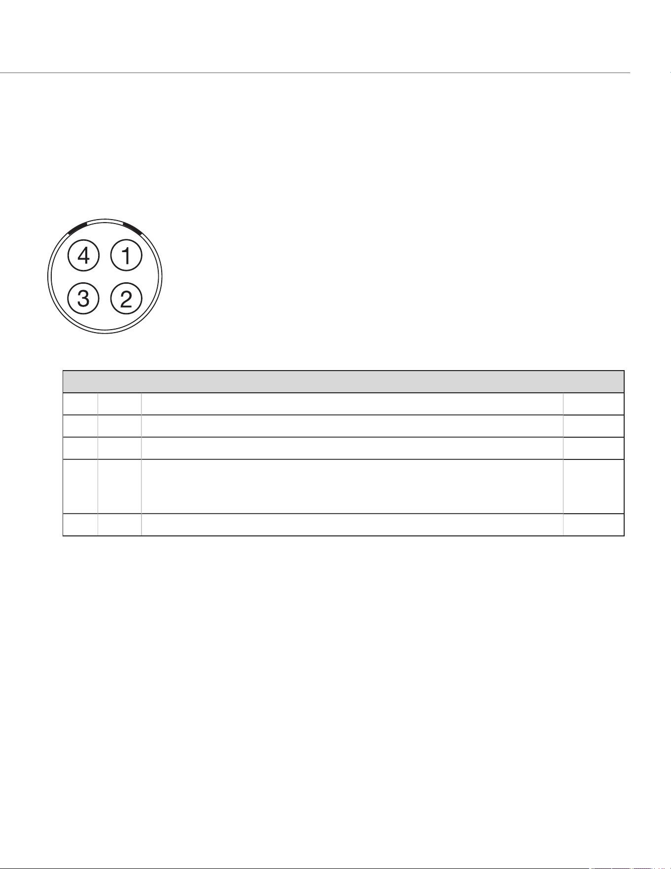
USB POWER
The USB power-out connector supplies 5V of power. The maximum sustained current draw is 1.5A.
NOTE: The USB connector only offers power out, and does NOT support USB communication.
DC-IN
The 4-pin 2B LEMO connector (LEMO EGJ.2B.304.CLA) accepts DC input power from 11.5V DC to 17V DC.
Figure: Front Face of the Connector (Looking at the Camera)
LEMO EGJ.2B.304.CLA CONNECTOR
PIN SIGNAL DESCRIPTION DIRECTION
1 14V VBATT (11.5 TO 18V DC) @ 9A In
2 Ground Common ground N/A
3 28V VBATT (18 to 30V DC) @ 3A
Exclusively powers attached accessories and lens control devices. Power from this pin
does NOT power the camera.
In
4 Ground Common ground N/A
NOTE: Mating connectors are FGJ.2B.304.CLLD62Z and FGJ.2B.304.CLLD52.
COP YRIGHT © 2020 PA N A VISION IN TERN ATION AL, L.P . FW : V-1.0.0| 14 1
PANAVISION MILLENNIUM DXL2
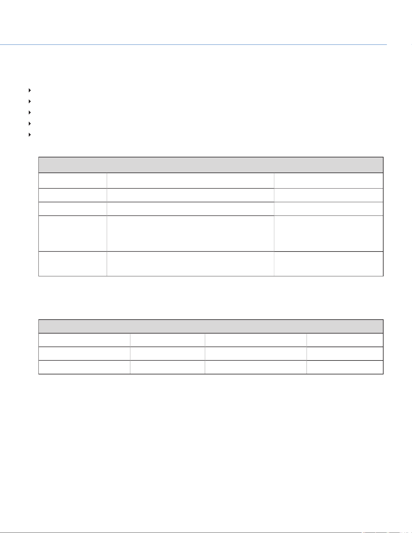
6G/3G HD-SDI
A standard 75 ohm BNC connector provides the following output:
Broadcast specification 3G-SDI (HD-SDI) video output (default mode is Clean)
Two (2) channels of embedded audio
Time of Day and Edge timecode
Record Tally flag
Clip name information (as SMPTE RP-188 VITC2 HANC metadata)
The 6G/3G-SDI (HD-SDI) output provides the formats described in the table below:
6G/3G-SDI (HD-SDI) OUTPUT FORMATS
1
VIDEO FEED
2
FREQUENCY (HZ)
3
SMPTE STANDARD
720p 23.98, 24.00, 25.00, 29.97, 30.00, 50.00, 59.94 SMPTE ST 292-1 (1.485 Gbps)
1080p 10-bit 4:2:2 23.98, 24.00, 25.00, 29.97, 30.00 SMPTE ST 292 (1.485 Gbps)
1080p 10-bit 4:2:2 50.00, 59.94, 60.00 3G-SDI
SMPTE ST 424 (2.970 Gbps)
SMPTE ST 425 (2.970 Gbps)
UHD 10-bit 4:2:2 23.98, 24.00, 29.97, 30.00 6G-SDI
SMPTE 2081(5.940 Gbps)
1. Ensure you select a frequency supported by your monitor.
2. The output is progressive scan (p); it does not support progressive segmented frame (PsF) or interlaced (i) scan formats.
3. The frequency options depend on project time base. If you have a non-drop frame project time base (such as 24.00), you can select only non-drop frame
frequencies. If you have a drop frame project time base (such as 23.98), you can select only drop frame frequencies.
75 OHM BNC CONNECTOR
PIN SIGNAL DESCRIPTION DIRECTION
Center 6G/3G-SDI SMPTE ST 424 Out
Shield/Screen GROUND Camera ground N/A
COP YRIGHT © 2020 PA N A VISION IN TERN ATION AL, L.P . FW : V-1.0.0| 14 2
PANAVISION MILLENNIUM DXL2
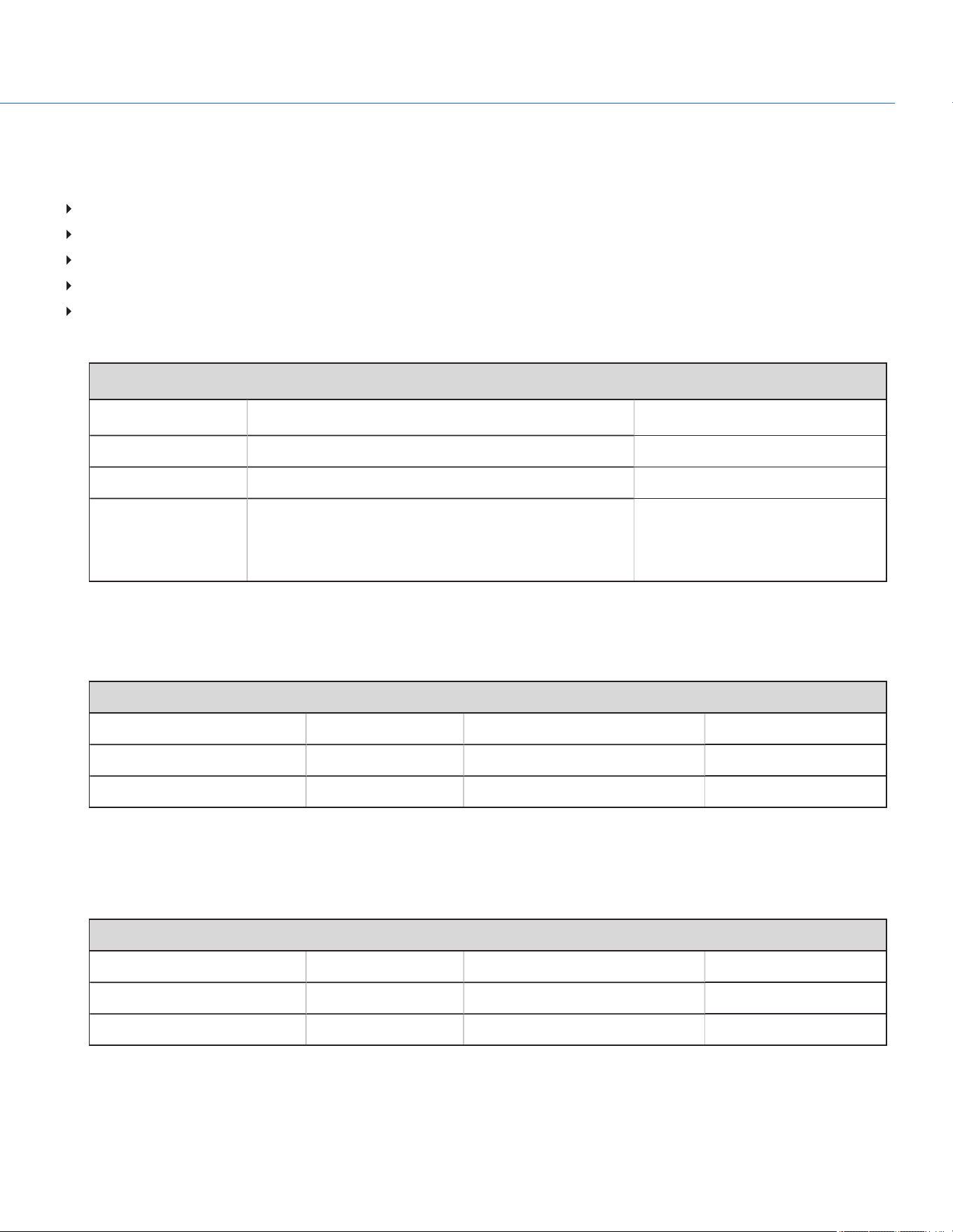
3G HD-SDI
A standard 75 ohm BNC connector provides the following output:
Broadcast specification 3G-SDI (HD-SDI) video output (default mode is Clean)
Two (2) channels of embedded audio
Time of Day and Edge timecode
Record Tally flag
Clip name information (as SMPTE RP-188 VITC2 HANC metadata)
The 3G-SDI (HD-SDI) output provides the formats described in the table below:
3G-SDI (HD-SDI) OUTPUT FORMATS
1
VIDEO FEED
2
FREQUENCY (HZ)
3
SMPTE STANDARD
720p 23.98, 24.00, 25.00, 29.97, 30.00, 50.00, 59.94 SMPTE ST 292-1 (1.485 Gbps)
1080p 10-bit 4:2:2 23.98, 24.00, 25.00, 29.97, 30.00 SMPTE ST 292 (1.485 Gbps)
1080p 10-bit 4:2:2 50.00, 59.94, 60.00 3G-SDI
SMPTE ST 424 (2.970 Gbps)
SMPTE ST 425 (2.970 Gbps)
1. Ensure that you select a frequency supported by your monitor.
2. The output is progressive scan (p); it does not support progressive segmented frame (PsF) or interlaced (i) scan formats.
3. The frequency options depend on project time base. If you have a non-drop frame project time base (such as 24.00), you can select only non-drop frame
frequencies. If you have a drop frame project time base (such as 23.98), you can select only drop frame frequencies.
75 OHM BNC CONNECTOR
PIN SIGNAL DESCRIPTION DIRECTION
Center 3G-SDI SMPTE ST 424 Out
Shield/Screen GROUND Camera ground N/A
RETURN
A standard 75 ohm BNC connector provides the ability to feed an HD-SDI signal into the camera. For more information, go to
"Allow Return Feed" on page60.
75 OHM BNC CONNECTOR
PIN SIGNAL DESCRIPTION DIRECTION
Center 3G-SDI SMPTE ST 424 In
Shield/Screen GROUND Camera ground N/A
COP YRIGHT © 2020 PA N A VISION IN TERN ATION AL, L.P . FW : V-1.0.0| 14 3
PANAVISION MILLENNIUM DXL2
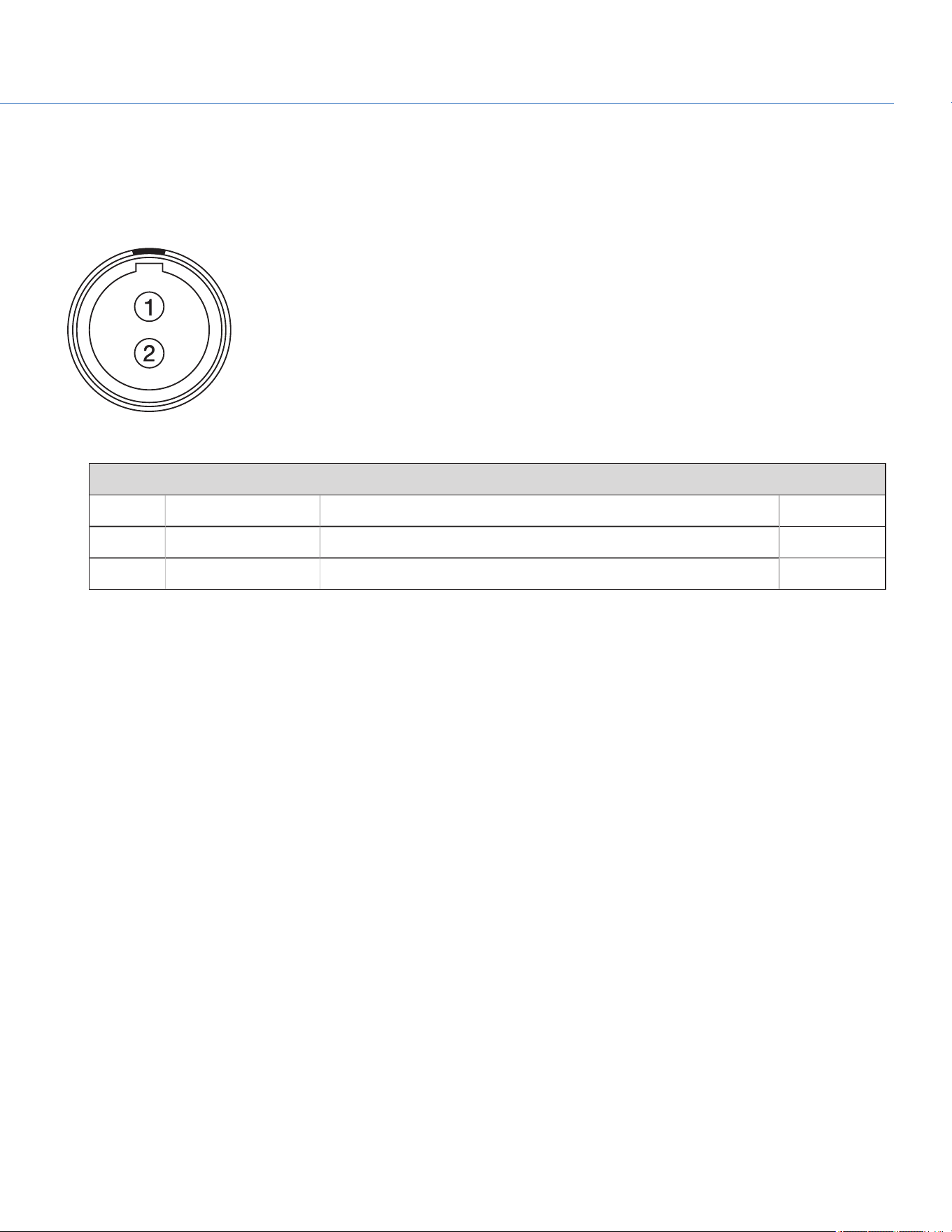
14V AUX POWER OUT
The DXLM Module offers one (1) 14V AUX power port.
The 2-pin 0B LEMO connector (LEMO EEG.0B.302.CLL) supplies unregulated (+) 11.5 to 17V DC battery pass-through power.
The maximum sustained current draw is 3.0A.
Figure: Front Face of Connector (Looking at the Camera)
LEMO EEG.0B.302.CLL CONNECTOR
PIN SIGNAL DESCRIPTION DIRECTION
1 GROUND Common ground N/A
2 +11.5 to +17V DC +11.5 to 17V DC unregulated battery pass-through power Out
NOTE: Mating connector is FGG.0B.302.CLAD.
COP YRIGHT © 2020 PA N A VISION IN TERN ATION AL, L.P . FW : V-1.0.0| 14 4
PANAVISION MILLENNIUM DXL2
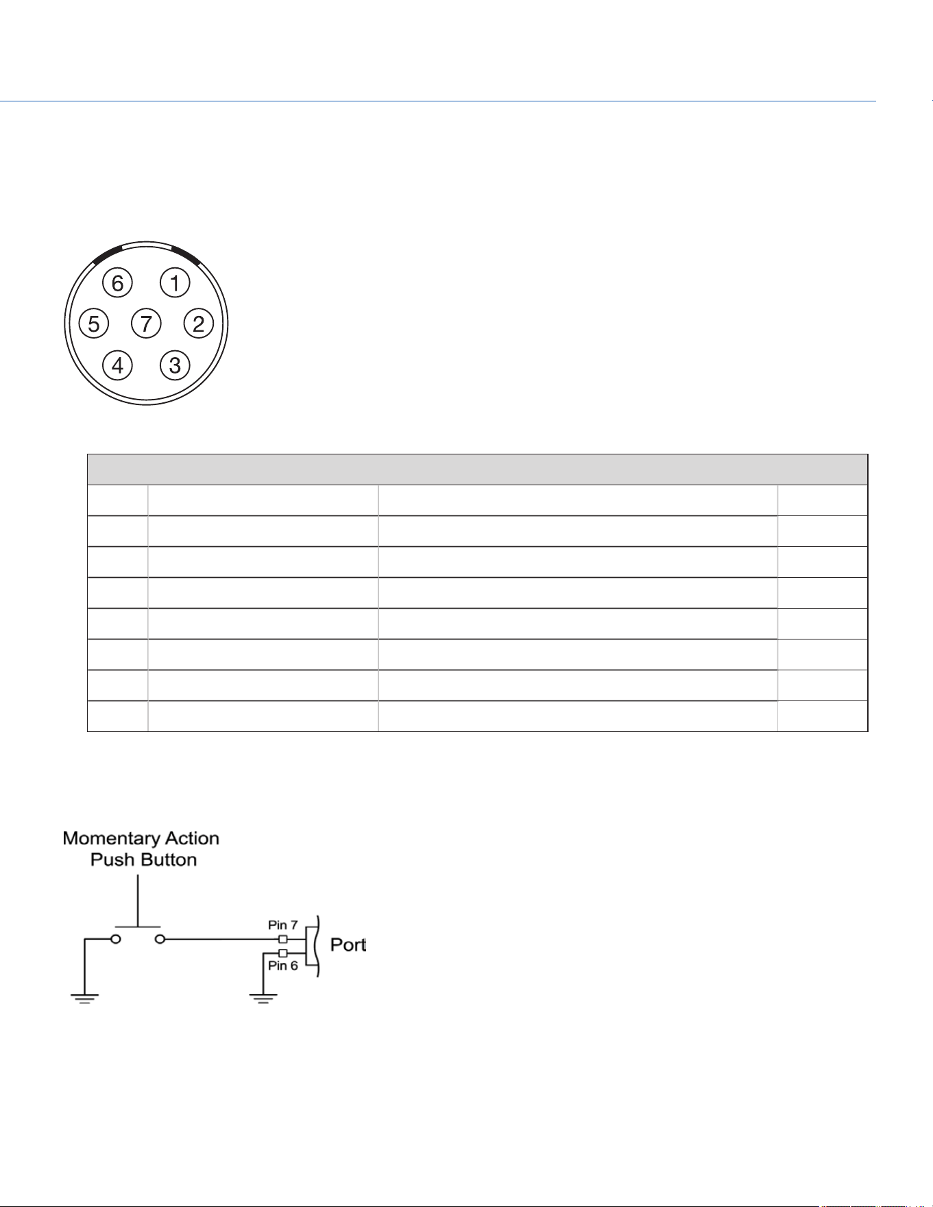
AUX POWER OUT
The 7-pin 1B LEMO connector supports RS232 and a General Purpose Input (GPI) trigger. The connector also offers auxiliary
power out, with a maximum sustained current draw of 2.0A.
To operate the GPI contact closure style trigger, short Pin 7 (GPI) to Pin 6 (ground).
Figure: Front Face of the Connector (Looking at the Camera)
7-PIN 1B LEMO AUX CONNECTOR
PIN SIGNAL DESCRIPTION DIRECTION
1 GND Camera ground N/A
2 RS232 RX RS232 RX (Receive) In
3 RS232 TX RS232 TX (Transmit) Out
4 +VBATT (11.5 to 17V DC) @ 2.0A +11.5 to +17 VDC unregulated battery pass-through power Out
5 NC No connection (NC) N/A
6 GND Camera ground N/A
7 GPI General Purpose In (GPI) trigger (active-low switch closure) In
NOTE: Mating connector is FGB.1B.307.CLAD52 (straight).
CONTACT CLOSURE STYLE TRIGGER BUTTON CIRCUIT
The diagram below shows the contact closure style trigger button circuit on the connector.
Figure: Contact Closure Style Trigger Button Circuit Diagram
COP YRIGHT © 2020 PA N A VISION IN TERN ATION AL, L.P . FW : V-1.0.0| 14 5
PANAVISION MILLENNIUM DXL2
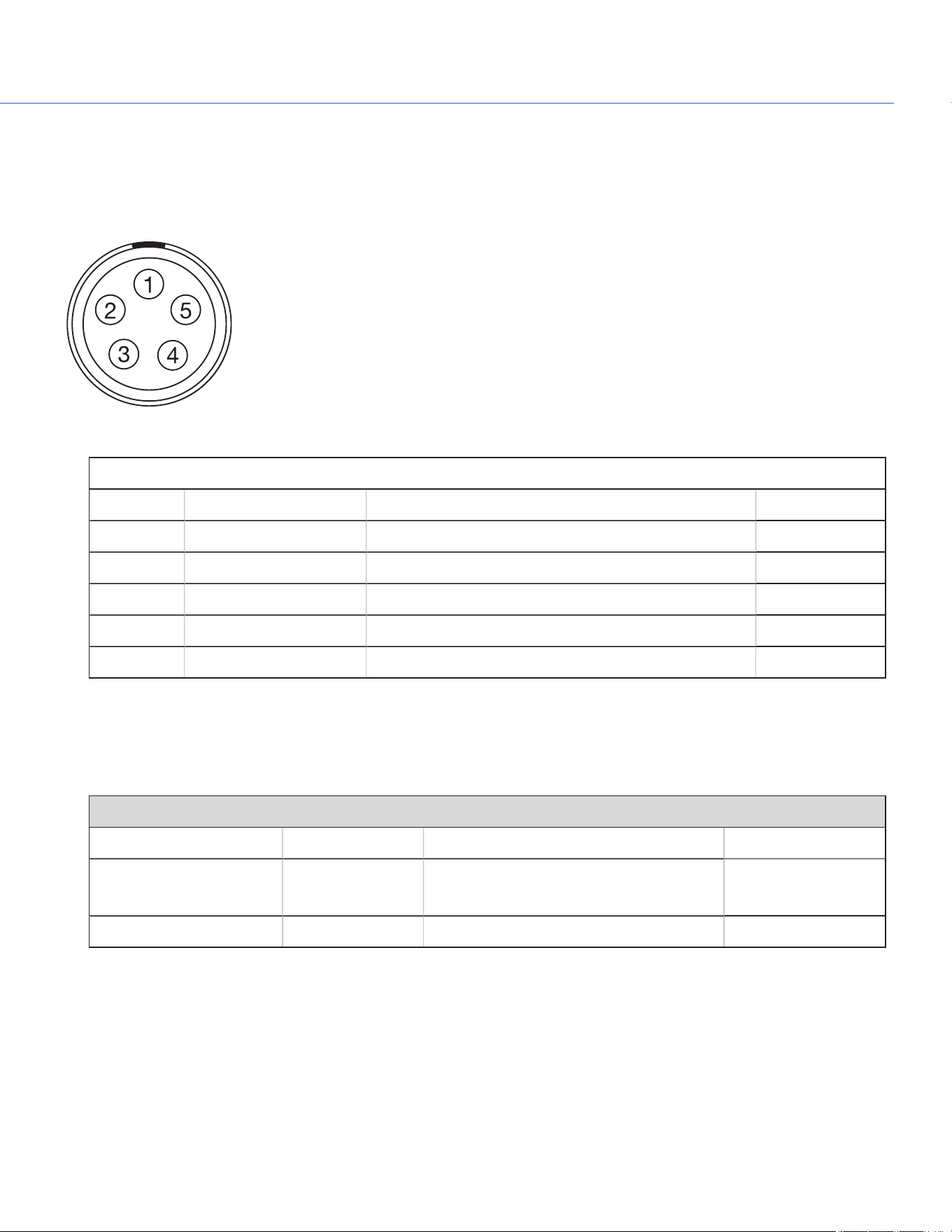
TIMECODE
The LEMO EAG.0B.305.CLN connector supports SMPTE timecode input and output. Pins 2 and 3 can be used together to
receive a balance SMPTE 12M serial timecode input. Pin 2 can be used by itself (leave pin 3 open) to receive a single-ended
SMPTE 12M serial timecode input. Pin 5 is a timecode output.
Figure: Front Face of Timecode (LEMO EAG.0B.305.CLN) Connector (Looking at the Camera)
LEMO EAG.0B.305.CLN CONNECTOR
PIN SIGNAL DESCRIPTION DIRECTION
1 GROUND Camera Ground N/A
2 TIMECODE IN(S) Timecode input - SMPTE single ended In
3 N/A No connection (NC) N/A
4 +5V OUT +5V out, 200 mA max Out
5 TIMECODE OUT SMPTE 12M Timecode output Out
NOTE: Mating connector is FHG.0B.305.CLAD.
GENLOCK
The 75 ohm BNC connector accepts incoming sync and genlock signals.
75 OHM BNC CONNECTOR
PIN SIGNAL DESCRIPTION DIRECTION
Center SYNC SMPTE ST 274
RS 170A Tri-Level Sync
In
Shield/Screen GROUND Camera ground N/A
COP YRIGHT © 2020 PA N A VISION IN TERN ATION AL, L.P . FW : V-1.0.0| 14 6
PANAVISION MILLENNIUM DXL2
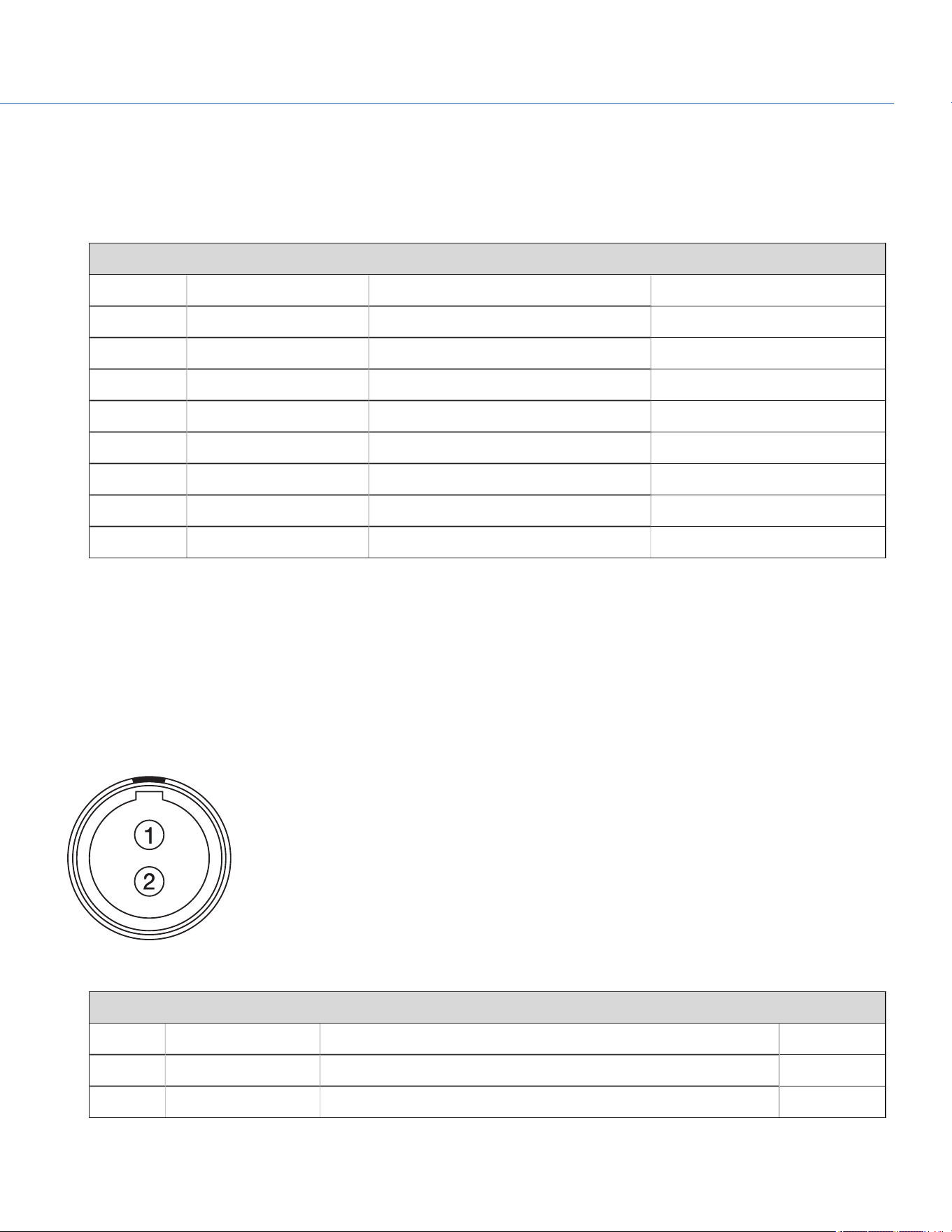
GIG-E
The GIG-E 8-pin RJ45 Ethernet connector provides a 1000BASE-T (IEEE 802.3ab) gigabit Ethernet connection for remote
camera setup, master/slave camera communication, and external metadata ingest. Since the GIG-E connector does not
support slower speeds (10BASE-T and 100BASE-T), ensure that any device you connect to supports 1000BASE-T.
GIG-E CONNECTOR
PIN SIGNAL DESCRIPTION DIRECTION
1
BI_DA+ Data pair A+
N/A
2
BI_DA- Data pair A-
N/A
3
BI_DB+ Data pair B+
N/A
4
BI_DC + Data pair C+
N/A
5
BI_DC - Data pair C-
N/A
6
BI_DB- Data pair B-
N/A
7
BI_DD+ Data pair D+
N/A
8
BI_DD - Data pair D-
N/A
LCD/EVF PORTS
Custom digital video and power interconnection between the camera and RED LCDs and EVFs. The pinout is not published.
14V AUX POWER OUT
The DXLM Module offers one (1) 14V AUX power port.
The 2-pin 0B LEMO connector (LEMO EEG.0B.302.CLL) supplies unregulated (+) 11.5 to 17V DC battery pass-through power.
The maximum sustained current draw is 3.0A.
Figure: Front Face of Connector (Looking at the Camera)
LEMO EEG.0B.302.CLL CONNECTOR
PIN SIGNAL DESCRIPTION DIRECTION
1 GROUND Common ground N/A
2 +11.5 to +17V DC +11.5 to 17V DC unregulated battery pass-through power Out
NOTE: Mating connector is FGG.0B.302.CLAD.
COP YRIGHT © 2020 PA N A VISION IN TERN ATION AL, L.P . FW : V-1.0.0| 14 7
PANAVISION MILLENNIUM DXL2
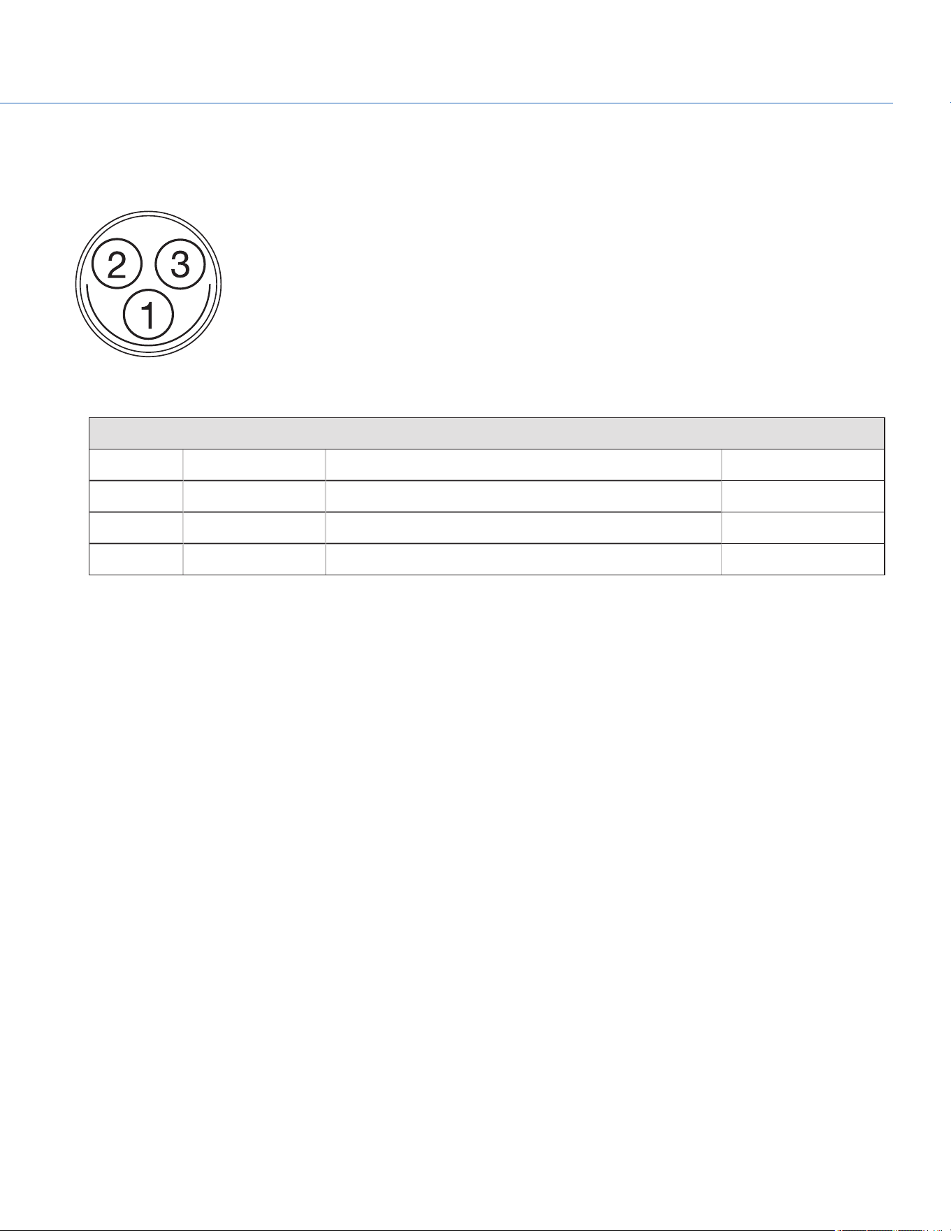
24V AUX POWER OUT
The DXLM Module offers two (2) Fischer 3-pin 102 connectors that up convert from 12V to 24V.
Figure: 24V Connector (Looking at the Camera)
FISCHER 3-PIN CONNECTOR
PIN SIGNAL DESCRIPTION DIRECTION
1 GROUND Common ground N/A
2 24V 24V Out
3 Trigger Active Low to start/stop record In
COP YRIGHT © 2020 PA N A VISION IN TERN ATION AL, L.P . FW : V-1.0.0| 14 8
PANAVISION MILLENNIUM DXL2

COP YRIGHT © 2020 PA N A VISION IN TERN ATION AL, L.P . FW : V-1.0.0| 149
PANAVISION MILLENNIUM DXL2
LENS INFORMATION
LENS MOUNT
The Panavision Millennium DXL2 features a built-in SP70 lens mount, which is compatible with Primo 70 Series lenses. The
lens mount is also compatible with select adaptors that support other lens mounts.
LENS WEIGHT AND LENS SUPPORT
Use a lens support system when mounting heavy or long lenses to your camera.
When mounting a heavy or long lens, ensure that the full weight of the lens is never directly on the camera or lens mount.
Mount the lens to the support system first, and then carefully mount the lens to the camera.
COP YRIGHT © 2020 PA N A VISION IN TERN ATION AL, L.P . FW : V-1.0.0| 150
PANAVISION MILLENNIUM DXL2
DEFAULT KEY FUNCTIONS
DEFAULT KEYS
ITEM KEY DEFAULT FUNCTION
Camera Right Side (Assistant
Side)
PWR/REC Full Press Record: Toggle
PWR/REC Press Two (2)
Seconds
Turn off camera
PWR/REC Press Five (5)
Seconds
Force turn off camera
Assistant A Press
1
Assistant A + Assistant B: Toggle lock/unlock all keys on
Assistant Side
Assistant B Press
1
Assistant A + Assistant B: Toggle lock/unlock all keys on
Assistant Side
Nav North Press Move cursor up
Nav South Press Move cursor down
Nav East Press Move cursor right
Select menu
Nav West Press Move cursor left
Return to the last menu
Nav Enter Press Navigation: Select
Navigation Wheel CW Move cursor down
Navigation Wheel CCW Move cursor up
Menu Press Access/Exit menus
Back Press Return to the last menu
1. Programmable key action.
ITEM KEY DEFAULT FUNCTION
Camera Left Side (Operator
Side)
Record Full Press Record: Toggle
Record Half Press AF: Start
User 1 Press
1
Not Assigned
User 2 Press
1
Not Assigned
User 1+2 Press Eject Media
Operator A Press
1
Operator A + Operator B: Toggle lock/unlock all keys on
Operator Side
Operator B Press
1
Operator A + Operator B: Toggle lock/unlock all keys on
Operator Side
Nav North Press Move cursor up
Nav South Press Move cursor down
Nav East Press Move cursor left
Select menu
Nav West Press Move cursor right
Return to the last menu
Nav Enter Press Navigation: Select
Navigation Wheel
CW
Move cursor down
Navigation Wheel
CCW
Move cursor up
Menu Press Access/Exit menus
Back Press Return to the last menu
1. Programmable key action.
COP YRIGHT © 2020 PA N A VISION IN TERN ATION AL, L.P . FW : V-1.0.0| 151
PANAVISION MILLENNIUM DXL2

COP YRIGHT © 2020 PA N A VISION IN TERN ATION AL, L.P . FW : V-1.0.0| 152
PANAVISION MILLENNIUM DXL2
MENU MAP
See the Menu Map on the following page.
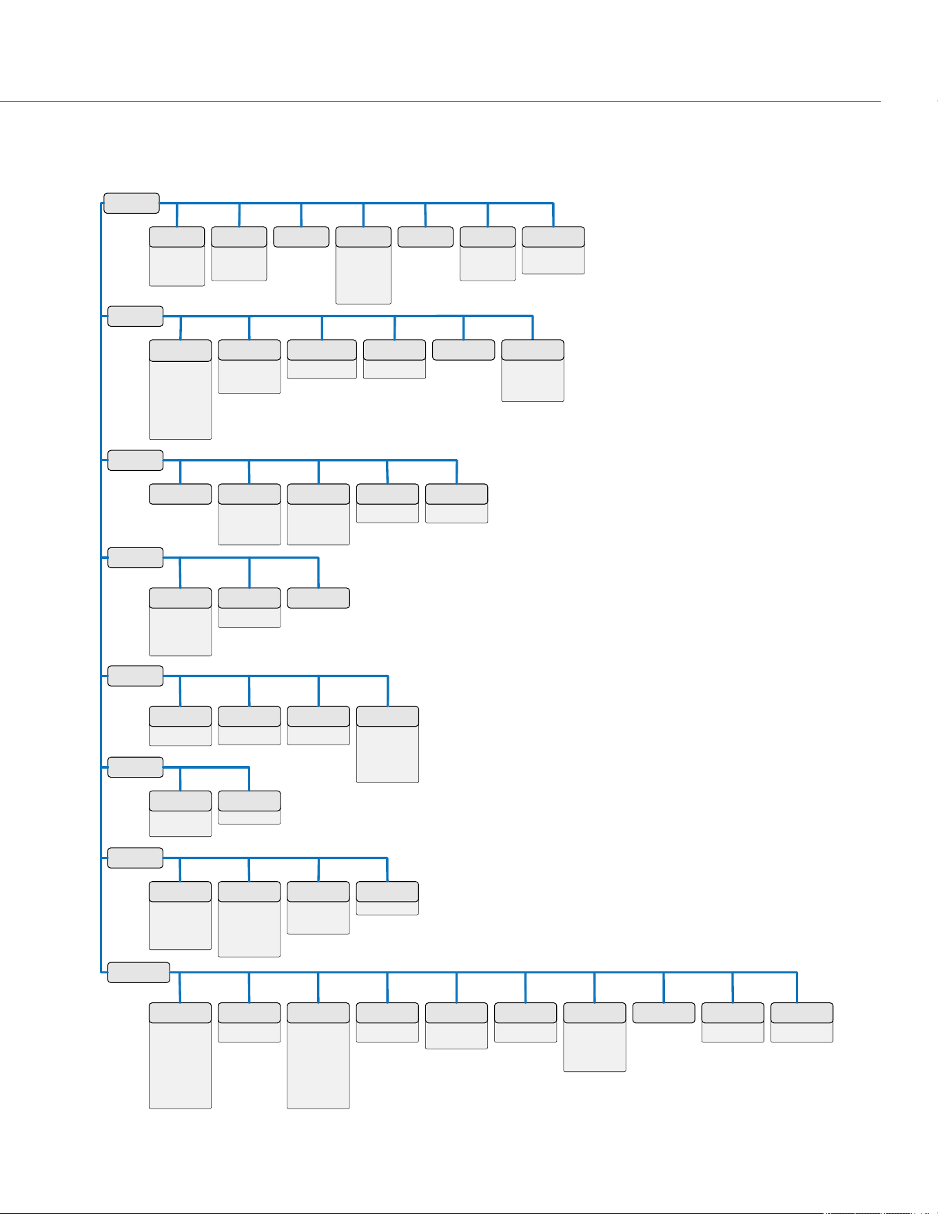
▶︎ Choose LUT
▶︎ LUT Import/Export
▶︎ Slope
▶︎ Power
▶︎ Offset
▶︎ Saturation
▶︎ Reset
▶︎ CDL Presets
▶︎ Power Out
▶︎ Power In
POWER
PROJECT
SETTINGS
MONITORING
MEDIA
LOOK
USER
PRESETS
AUDIO
NETWORK
MAINTENANCE
▶︎ SDI 1
▶︎ SDI 2
▶︎ SDI 3
▶︎ SDI 4
▶︎ SDI 5
▶︎ UHD
▶︎ Assistant Port
▶︎ Top Port
▶︎ Operator Port
▶︎ All Monitor Flip
MONITOR
PREFERENCES
▶︎ Spherical
▶︎ Anamorphic 2
▶︎ Anamorphic 1.3
▶︎ Anamorphic 1.25
▶︎ Look Around
RESOLUTION
▶︎ File Format
▶︎ REDCODE
▶︎ Apple ProRes
▶︎ Avid DNxHD/HR
CODEC TIMEBASE
▶︎ Camera ID
▶︎ Camera Position
▶︎ Camera Color
▶︎ Production
▶︎ Director
▶︎ DoP
▶︎ Unit
SLATE SHUTTER
▶︎ Display Mode
▶︎ Source
▶︎ LTC Out
▶︎ Wireless Channel
TIMECODE
▶︎ Duration
▶︎ Always Trigger
▶︎ Trigger Pre-Record
PRE-RECORD
▶︎ Frame Line 1
▶︎ Frame Line 2
▶︎ Frame Line 3
▶︎ Cross Hair / Shading
FRAME LINES
▶︎ In Camera
▶︎ On Media : \overlays
OVERLAY
IMPORT/EXPORT
▶︎ Signal
▶︎ Tone
TEST SIGNALS Reduce Judder
EJECT MEDIA
▶︎ Reel Number
▶︎ Camera ID
▶︎ Camera Position
▶︎ Edge TC Start
▶︎ Quick Format Media
QUICK FORMAT
▶︎ Reel Number
▶︎ Camera ID
▶︎ Camera Position
▶︎ Edge TC Start
▶︎ Full Format Media
FULL FORMAT
▶︎ FAT32
▶︎ UDF
FILE SYSTEM
▶︎ Media Download
Firmware
UTILITIES
CDL 3D LUT COLOR SPACE
▶︎ Channel 1/2
▶︎ Channel 3/4
▶︎ Pre-Amp Gain
CONTROL
▶︎ Monitor Mix
MIX
▶︎ Mode
▶︎ AdHoc Settings
▶︎ Infrastructure
settings
▶︎ Status
▶︎ MAC
WIFI
▶︎ DHCP
▶︎ IP Address
▶︎ NetMask
▶︎ Gateway
▶︎ Camera to Camera
▶︎ External Control
▶︎ MAC
ETHERNET
▶︎ Camera ID
▶︎ Group ID
▶︎ Target
▶︎ Target ID
CAMERA
▶︎ Ctrl Protocol
SERIAL
▶︎ In Camera
▶︎ On Media :\presets
CAMERA
PRESETS
▶︎ In Camera
▶︎ On Media :\looks
LOOK PRESETS
▶︎ Operator
▶︎ Assistant
HOME PAGE
▶︎ Operator A
▶︎ Operator B
▶︎ Assistant A
▶︎ Assistant B
▶︎ 1
▶︎ 2
▶︎ 1+2
KEY MAPPING
▶︎ Mode
▶︎ Maximum Record
Speed
▶︎ Maximum Preview
Speed
▶︎ Target Temperature
▶︎ Post Record Delay
▶︎ Temperature Sensor
▶︎ Temperature Core
▶︎ Fan Speed 1
▶︎ Fan Speed 2
FAN CONTROL
▶︎ File Format
▶︎ Camera Info
▶︎ Media Info
▶︎ Recording
▶︎ ProRes
▶︎ DNxND/HR
▶︎ Look
▶︎ Attached Modules
▶︎ Other
▶︎ Connected RCP
Clients
SYSTEM
STATUS
▶︎ Sync
▶︎ BRAIN GPIO
GPIO/SYNC
▶︎ Current Settings
▶︎ Black Balance
Import/Export
BLACK
BALANCE
▶︎ Date/Time
▶︎ Time Zone
DATE/TIME
▶︎ Enable Sounds
▶︎ Record Start
▶︎ Record Stop
▶︎ Tag Still Frame
▶︎ EVF Tally Light
▶︎ SSD Tally Light
INDICATOR SAVE LOG
▶︎ Reset Defaults
▶︎ Wipe Camera
CAMERA
DEFUALT
▶︎ Camera
▶︎ Media
UPGRADE
▶︎ Exposure
▶︎ Power
▶︎ VU Meter
▶︎ Histogram
▶︎ Media
INFO MODE
COP YRIGHT © 2020 PA N A VISION IN TERN ATION AL, L.P . FW : V-1.0.0| 153
PANAVISION MILLENNIUM DXL2
