The next-generation, enhanced
variable white LED soft light.
ISSUE 2.5 | MARCH 2024
User manual of SONARA™
© 2024 Panalux Ltd. All Rights Reserved.
The next-generation, enhanced
variable white LED soft light.
ISSUE 2.5 | MARCH 2024
User manual of SONARA™
© 2024 Panalux Ltd. All Rights Reserved.
T A B L E O F
CONTENTS
Powering Options
Comms Panel
Accessories
05 Operation
User Interface
Factory Reset
Lock Mode
Rotary Encoder
Selector Buttons
Memory Buttons
Backlight
Modes
06 Control Features & Options
Source Select
Control/Dimming Curves
Tungsten Emulate Mode
Important Note on Dimming Curves
Control Output
Control Gamut
Control Camera LUTs
Control Priority
DMX Personalities
DMX Personalities - Channel
Assignments
RDM
SONARA™ RDM Sensors
SONARA™ Menu Tree
07 General
Power Characteristics
Physical Characteristics
Fault Finding Tips
Optical Characteristics
Warnings & Cautions
Spare Parts & Accessories
08 Appendix
Gel Library
Source Emulation List
Overall Dimensions &
Rigging Centres
01 Important Information & Warnings
Safety Information
Changes
Measuring Correlated Colour
Temperature (CCT), Colour x y
Flicker-Free Filming
Gel/Filter Emulations &
Source Matching
02 Introduction
About This User Manual
Additional Documentation
Technical Support
Disclaimer
03 User Instructions
General Notes
Fixture Setup
Attachment of Safety Bonds
Ventilation
Additional Safety Considerations
Power Supply
Safety Cables
04 Fixture Overview
SONARA™ Components & Controls
Controller
SONARA™ Mounting Components
04
05
05
05
06
06
07
08
08
08
08
09
10
10
11
11
11
12
12
13
14
15
16

IMPORTANT
INFORMATION &
WARNINGS
01
Safety Information
The symbols below are used throughout this manual to
identify important safety information.
Heed all warnings and safety information.
This product is not user servicable.
Changes
Panalux provides this manual ‘as is’ without warranty of any
kind, either expressed or implied, including but not limited
to the implied warranties or merchantability and tness for a
particular purpose. Panalux may make improvements and/or
changes to the product(s) and/or the programmes described
in this publication at any time without notice. This publication
could contain technical inaccuracies or typographical errors.
Changes are periodically made to the information in this
publication; these changes are incorporated in new editions
of this publication.
Measuring Correlated Colour Temperature
(CCT), Colour x y
The SONARA™ utilises an LED source that is optimized
for the lm, TV, and image capture industries. Older
colour meters cannot be used to accurately read the
Correlated Colour Temperature (CCT) of SONARA™ and
other discontinuous spectrum light sources. Older colour
meters are designed for a full spectrum source such as
incandescent lights. These meters possess only 3 sensors
to measure the light output: red, green, and blue. As such,
a narrow band or discontinuous spectrum light source may
not read correctly. Colour meters such as the Sekonic C800
Spectromaster or UPR Tech MK 350 will provide excellent
measurements and include TLCI and SSI metrics
as standard.
Panalux have taken great care in ensuring that the
CCT and colour spectrum of gel emulations of the light
emanating from SONARA™ closely matches traditional
tungsten and discharge light sources. This allows you to
easily place SONARA™ alongside your traditional lighting
xtures. If in any doubt, it is the user’s responsibility, as is
customary, to shoot image capture tests when combining
sources employing different core technology—such as
HMI, orescent, tungsten, or simple RGB and bi-colour
LED xtures—to ensure compatibility. Shoot tests using
the camera setup to be used for the project (capture
gamut, LUTs, etc.). The spectral power density curve, chip
proles, and coordinates will be different from other xtures.
Matching x y coordinates will only guarantee proximity to the
x y coordinates. It will not guarantee a colour match to eye
or to camera with another light source.
IMPORTANT
INFORMATION
Warning, Danger, or Caution
Risk or injury to yourself, third party, or
the product
Risk of electric shock
Risk of severe electric shock
PANALUX SONARA USER MANUAL
5 ISSUE 2.5 | MARCH 2024

Flicker-Free Filming
The only way to guarantee icker-free
lming at any frame rate and shutter
angle is by using pure DC power,
carbon arc sources, or daylight. There
is a chance of icker in every other
scenario with articial light, even with
tungsten mains-powered xtures.
Visible icker is also affected by
postproduction. Where the contrast
is increased, the icker becomes
more visible.
SONARA™ has been validated icker-
free at any dim position up to 10,000
fps. SONARA™ has been tested
across a range of dim settings, CCTs,
and colours with the high-speed Vision
Research Phantom camera as well
as Arri Alexa Mini, with the cameras
at multiple shutter angles. Not all
manufacturers are as thorough. Test
whenever in doubt, particularly when
shooting high speed.
Flicker factor, the relationship
between the maximum and minimum
illuminance exhibited in the icker,
can be measured with a icker meter.
100% means the light goes totally dark
at minimum. HMI electronic ballasts
tend to have a icker factor around
1–3%, tungsten lights 0–10%.
With multi-colour LED xtures, in
particular older Stage and Architectural
LED xtures where compatibility with
lm and digital cameras wasn’t a
consideration in their design, individual
colour channels can be out of sync,
causing different colour mixes on
different frames, which can cause
issues with high-speed lming, stop-
frame animation, and still photography.
If in doubt, test and review. Check
the footage after running a test, and
be aware that some digital cameras
do not replay raw footage, so it is
advisable to download les rst and
then check.
Gel/Filter Emulations and
Source Matching
SONARA™ comes pre-loaded with
a range of LEE Filter gel emulations.
Since the base spectrum of the
SONARA™ at 3200K and 5600K is
not identical to a tungsten or daylight
source, the gel presets are merely
emulations. Due to the inherent
technology, no LED bi-colour or multi-
chip source can perfectly match the
spectrum of a subtractive lter laid
over a tungsten or daylight source.
Even if the x y coordinates appear to
be a good match, the spectrum will
be different, and the camera will read
subtle differences.
If in doubt, test before shooting.
6
PANALUX SONARA USER MANUAL
ISSUE 2.5 | MARCH 2024

INTRODUCTION
02
About This User Manual
This manual provides installation, operation, and maintenance instructions for all SONARA™ professional lighting xtures.
This manual applies to the following software versions:
v1.17
Additional Documentation
For more information regarding DMX512 systems, refer to the DMX512/1990 & AMX 192 Standards publication available from
United States Institute for Theatre Technology, Inc. (USITT). Contact by post at USITT, 6443 Ridings Road, Syracuse, NY,
13206-1111, USA; by phone on 1-800-93USITT; or online at www.usitt.org.
Art-Net is used for transmitting DMX lighting control protocol and RDM over the User Datagram Protocol (UDP) of the Internet
Protocol suite. It is based on the TCP/IP protocol suite and used to communicate between nodes/lighting xtures and a
lighting desk, typically on a private local network such as Ethernet. Art-Net can address over 30,000 universes.
Art-Net™ designed by and copyright Artistic Licence Holdings Ltd.
Technical Support
For technical support, contact Panalux on +44 20 8233 7000 or at info@panalux.biz.
Disclaimer
Panalux and SONAR A™ are trademarks of PANAVISION registered in the U.S. and other countries. All other brand or product
names which may be mentioned in this manual are trademarks or registered trademarks of their respective companies. This
manual is for informational use only and is subject to change without notice. Please check www.panalux.biz for the latest
version. Panalux assumes no responsibility or liability for any claims resulting from errors or inaccuracies that may appear in
this manual.
INTRODUCTION
PANALUX SONARA USER MANUAL
8 ISSUE 2.5 | MARCH 2024

USER
INSTRUCTIONS
03

USER INSTRUCTIONS
General Notes
1. Please read through this manual carefully before operating SONARA™. Keep this manual for future reference.
2. There are numerous safety instructions and warnings that must be adhered to for your own safety.
3. SONARA™ is not intended for residential use. It is only intended for use in a professional studio.
4. SONARA™ must only be serviced by a qualied individual.
5. SONARA™ is rated as IP20, for indoor use and in a dry environment.
6. SONARA™ is not certied for use in hazardous locations.
7. SONARA™ operating temperature is within the range of 0 to 40°C (32 to 104°F).
8. Do not connect to a variable power supply such as a dimmer rack or variac.
9. Use only approved spare parts and accessories. (Refer to Spare Parts/Accessories list on page 37.)
1. Read these safety instructions carefully to ensure SONARA™ and its accessories are used safely.
2. Ensure the 28mm spigot is securely mounted onto the yoke before rigging.
3. For an alternative method of hanging SONARA™, threads are present on the xture for attaching an M12 eye bolt in
each corner. Ensure the M12 eye bolts are securely attached to SONARA™ before rigging.
4. 6 threads are available on the rear for mounting quick triggers, 1 in each corner and 2 on the outer edge, roughly aligned
with the centre line and yoke mounting position.
5. The combined weight of SONARA™ units should be considered when choosing suitable safety bond(s). The safety bond
assembly should be rated at the combined weight of the xture and accessories present. Fixture weights can be found in
the Physical Characteristics section of the manual.
6. When hanging SONARA™, always use secondary safety cables of suitable length (as short as possible) attached to the
safety eye or tted M12 eyebolts. (Detailed on page 11). Do not use the yoke to secure safety cables.
7. For safety purposes, ensure that the yoke locking handle is correctly tightened when manipulating SONARA™ in the
required orientation. NOTE: If the locking handle is not tightened correctly, the xture may tip forward.
8. Lifting handles are provided on the yoke. Ensure the yoke locking handle is tightened before lifting.
9. If SONARA™ is to be used with the yoke detached, accessory handles are available upon request.
10. Ensure the connection cables and any other cables are routed carefully to avoid snagging and pulling.
11. Ensure SONARA™ is stored within the range of -20 to +60°C (-4 to +140°F).
Fixture Setup
PANALUX SONARA USER MANUAL
10 ISSUE 2.5 | MARCH 2024
Ventilation
1. Do not cover air ventilation slots on SONARA™, or the xture may overheat.
2. Do not use SONARA™ outdoors or in a wet environment without approved accessories. (See the table on p. 37 for
outdoor accessories.)
3. Keep SONARA™ a minimal distance of 0.1m (4 inches) away from ammable materials/objects.
Additional Safety Considerations
1. Do not open SONARA™ when the xture is powered.
2. Allow SONARA™ to cool before servicing, as internal
parts may be hot.
3. Do not alter the design of SONARA™ or tamper with
any of the safety features.
4. Do not look directly into SONARA™ bare light source as
it may be harmful to the eyes.
5. SONARA™ reaches a maximum surface temperature of
85ºC. Please ensure contact on the surface by persons
or materials is avoided when the xture is operating.
6. Do not operate SONARA™ if there are any signs of
physical damage. If damage is visible or suspected,
contact Panalux Engineering Dept.
7. Before using SONARA™, check for any of the defects
listed in the adjacent table.
Part Possible Defect
Power cable Physical damage, cut, burnt
Locking handle Physical damage, loose
Spigot Physical damage, loose
Lifting eye Physical damage, loose
Venting ports Physical damage, bent, covered
Yoke Physical damage, loose
Casing Physical damage
Corner protectors Physical damage, loose
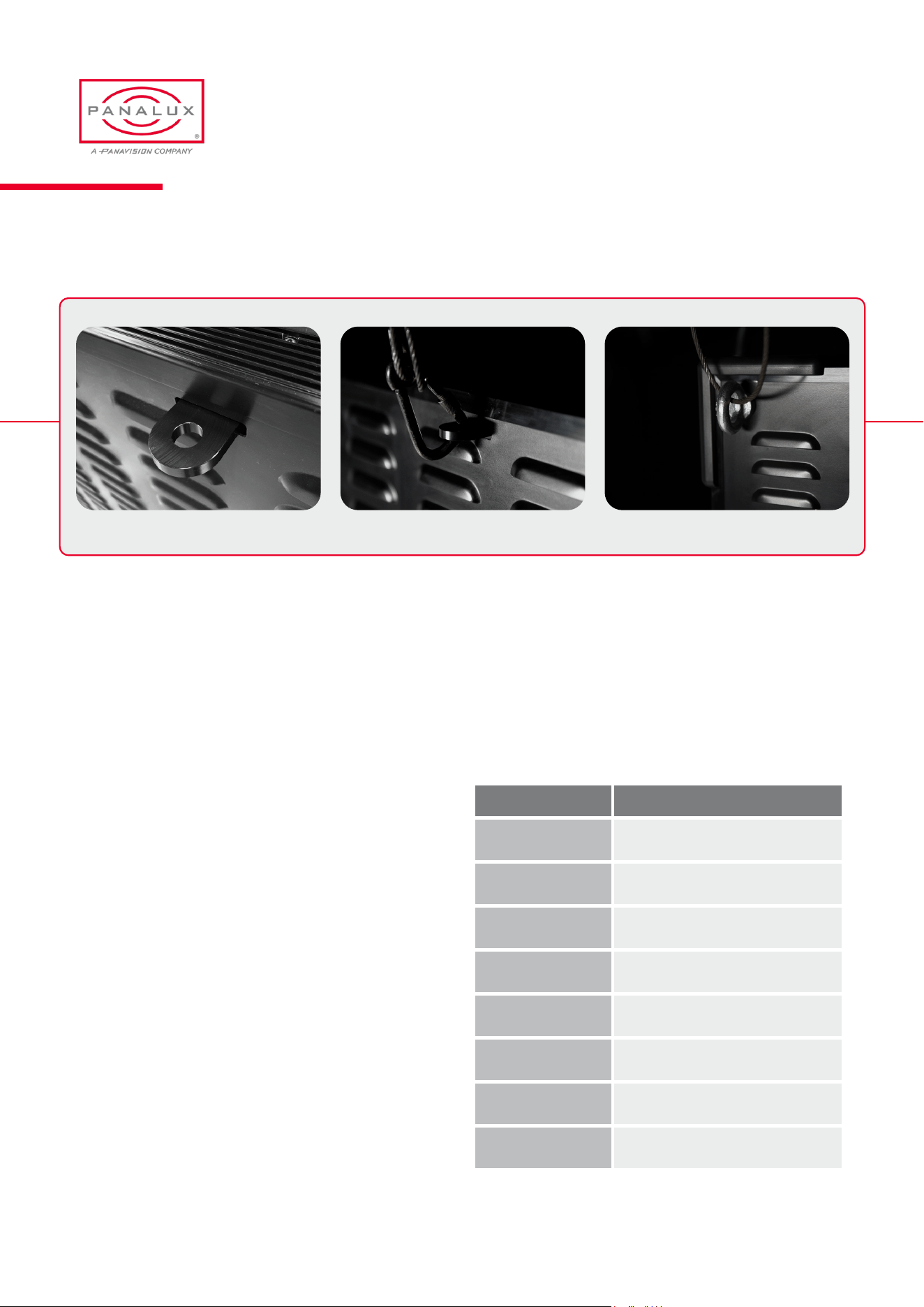
Fitted Safety BondSafety Bond Mounting Point Fitted Safety Bond (Eyebolt)
Attachment of Safety Bonds
PANALUX SONARA USER MANUAL
11 ISSUE 2.5 | MARCH 2024
Power Supply
1. Ensure the power cable is disconnected
before servicing.
2. SONARA™ only uses a mains connection. Do not
connect to a variable supply such as a dimmer rack,
variac, or inverter.
3. The power cable should be plugged into SONARA™
before switching the mains power supply ON. The
mains power supply should be switched OFF before
removing the power cable.
4. SONARA™ is shipped with a 7A (4:4) or 3A (3:2) fuse in
the fuse holder. For use in 110V locations, this should
be changed to a 15A (4:4) or 6A (3:2) version (additional
fuses not included).
Safety Cables
1. A minimum of one safety cable MUST be used when
hanging SONARA™ from its yoke or eye bolts or
using quick triggers. The length should be as short as
possible to reduce travel distance if the primary
hanging fails.
2. The safety bond slot (as shown on page 11) MUST be
used to attach a safety bond.
3. Ensure safety bonds are capable of supporting the
combined load of the SONARA™ and accessories.
Note
SONARA™ has been built to conform to international
regulatory standards relating to professional lighting
equipment. Any modication made to SONARA™ will void
the manufacturers’ warranty.
Approvals
EU
EN 55015:2013
EN 61547:2009
EN 61000-3-2:2014
EN 61000-3-3:2013
EN 61000-4-2:2009
EN61000-4-3:2006+A1:2008+A2:2010
EN 61000-4-4:2012
EN 61000-4-5:2006
EN 61000-4-6:2009
EN 61000-4-8:2010
EN 61000-4-11:2004
FCC
47 CFR of part 15
CSA
and UL
CSA C22.2 No. 250.4-14
CAN/CSA C22.2 No. 250.13-14
UL Standard No. 153
UL Standard No. 8750
Certications
ROHS
EPA3050B:1996
EN1122B:2011
EPA3052:1996
EPA7196A:1992
APE3540C:1996
EPA8270D:2007
Europe
EN / IEC 62471
PANALUX SONARA USER MANUAL
12 ISSUE 2.5 | MARCH 2024

FIXTURE
OVERVIEW
04
SONARA™ Components & Controls
SONARA™ units are powerful light xtures that incorporate
Panalux’s high-quality proprietary LED arrays. This LED
source provides the user with a large volume of high-quality
white light at a stable and repeatable CCT, emulating
traditional sources and a vast array of tints.
SONARA™ can be controlled in the following ways:
• Via the local controller attached to the back of the xture.
• Via an external DMX512 signal (5-pin DMX).
• Via wireless DMX.
• Via RJ45 port with ethernet connection.
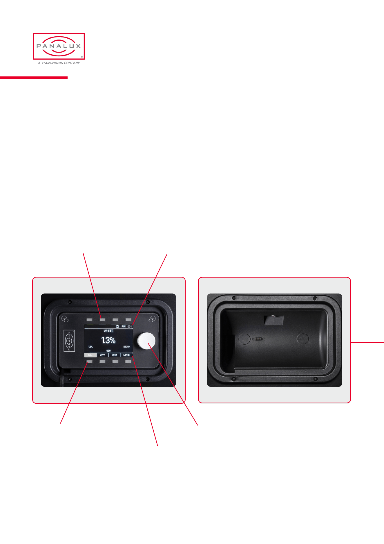
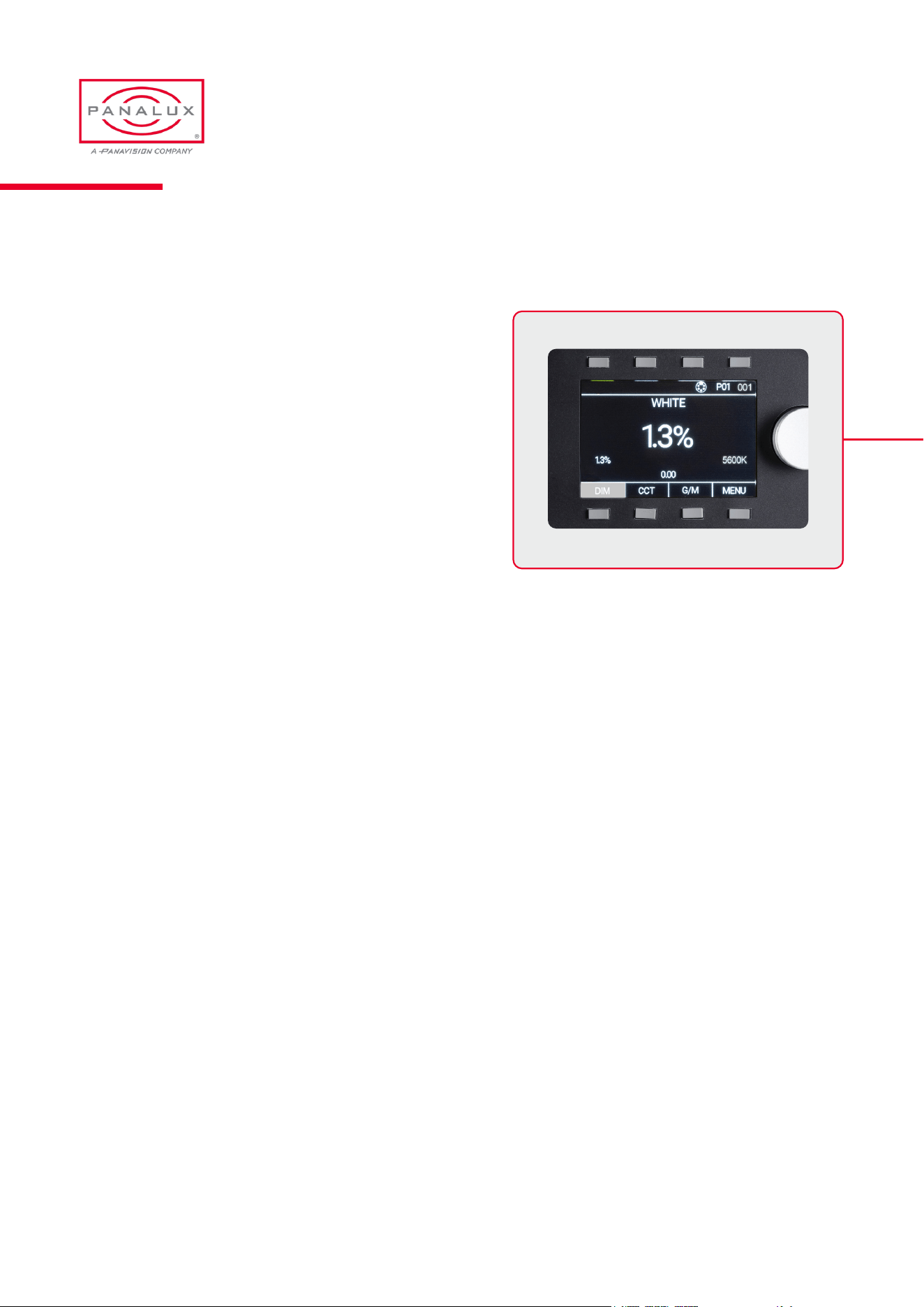
The SONARA™ user interface/wired remote have
been designed to provide a clear and simple display of
essential information.
The controller features 1 rotary push encoder, 4 selector
buttons (bottom), and 4 memory buttons (top).
The 4 selector buttons are identied with ‘soft’ labels on the
display depending on selected mode.
In white mode (shown), the display will always show:
Dim position (percentage)
CCT Green / Magenta bias
DMX base address
DMX personality
DMX control source (wired, wireless, Art-Net)
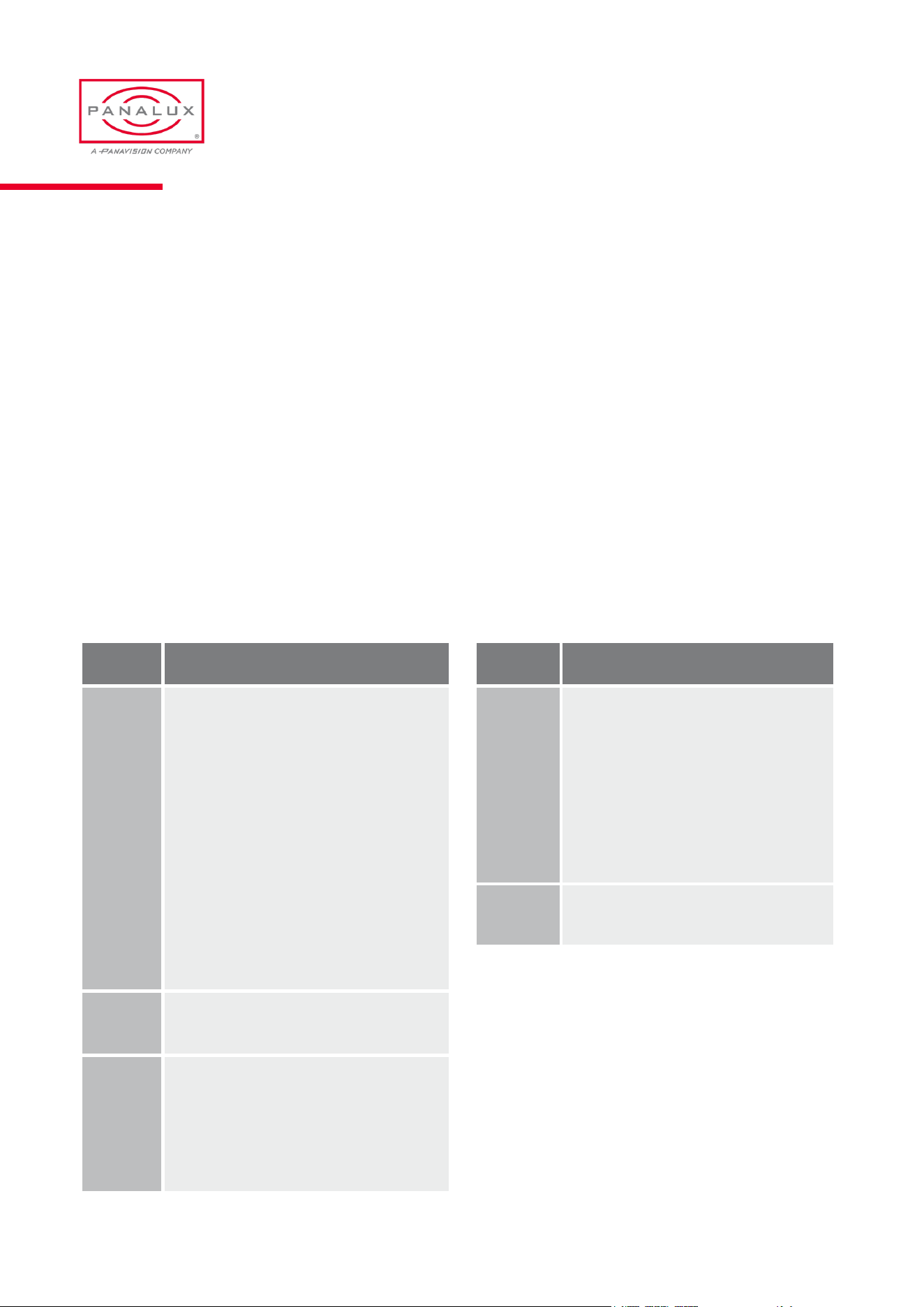
Comms Panel
Controller
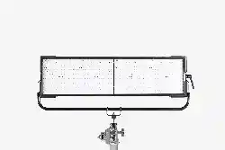
SONARA™ 4:4 Rear View
FIXTURE OVERVIEW
PANALUX SONARA USER MANUAL
14 ISSUE 2.5 | MARCH 2024
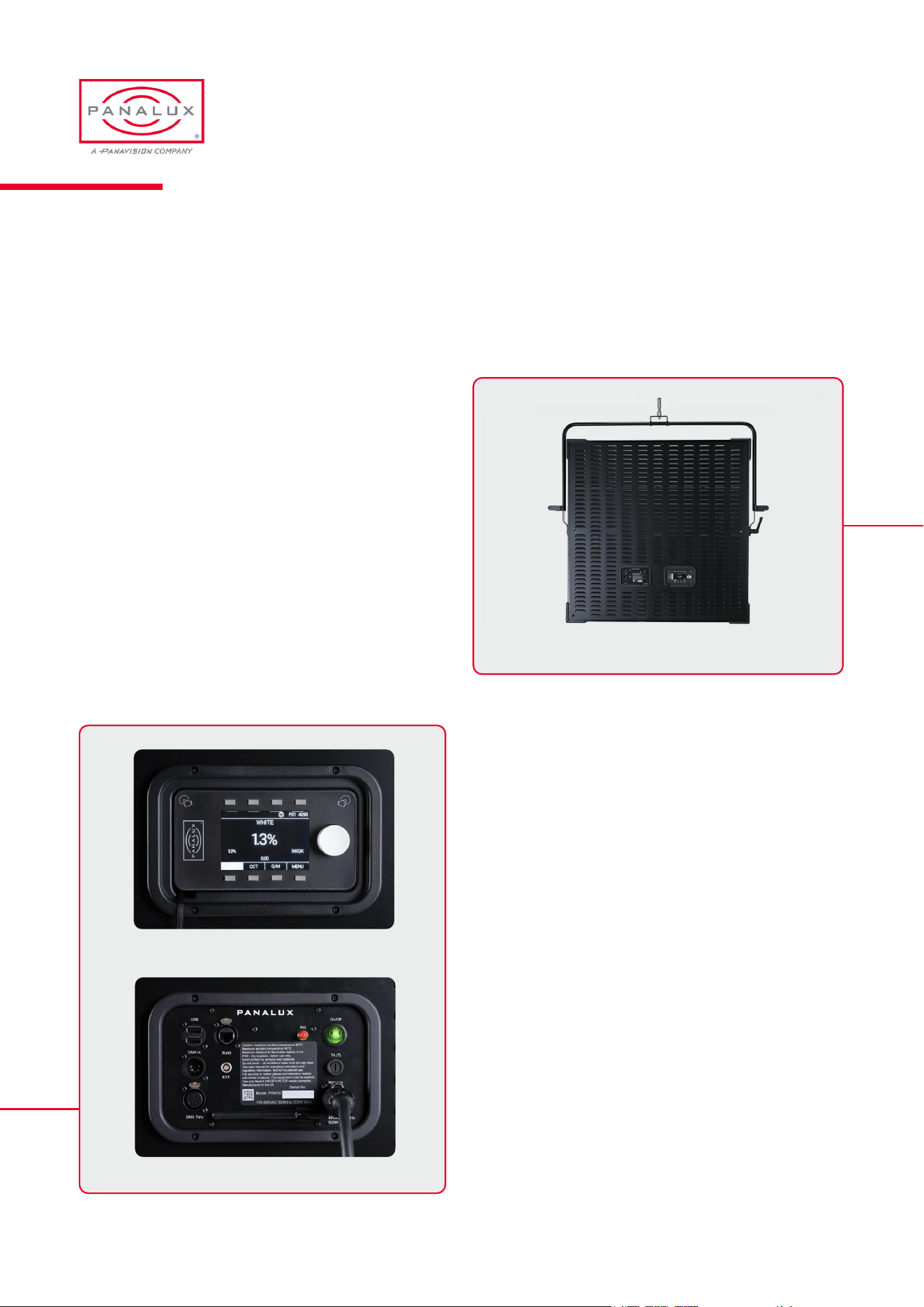
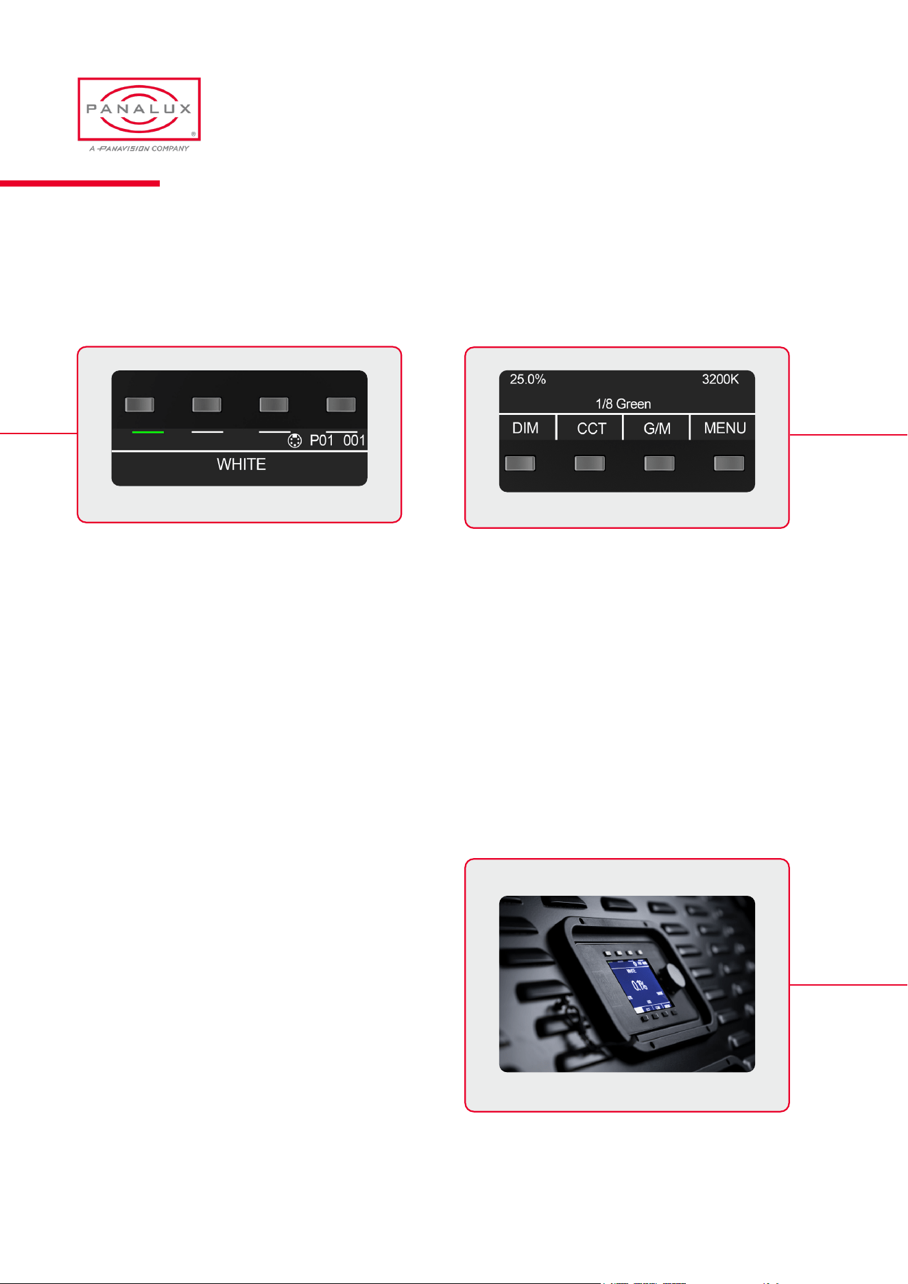
Controller
The controller until can be detached from the xture and linked with the supplied 4m accessory cable, enabling wired remote
control when the xture is out of reach.
The 4m cable connects to the xture by plugging one end into the Lemo connector on the rear of the controller and the other
end of the cable connects to the Lemo connector inside the controller holder.
The controller is attached into to the xture holder using powerful magnets. There is a D ring on the back plate of the xture
to secure the controller safety lanyard with a quick release for situations when SONARA™ is rigged at height.
Empty Controller HolderController Main Screen
Selector buttons with soft labels
User memory buttons
Rotary push encoder
Menu Bar
Status Bar
PANALUX SONARA USER MANUAL
15 ISSUE 2.5 | MARCH 2024
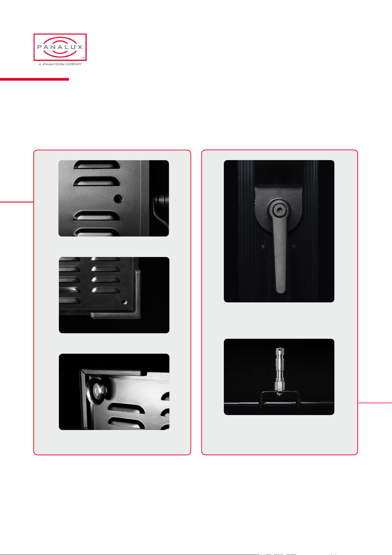
SONARA™ Fixings
Spigot
Locking Handle
Corner M12 Mounting Points
Mounting Point Fitted With M12 Eyebolt
Centre M12 Mounting Points
PANALUX SONARA USER MANUAL
16 ISSUE 2.5 | MARCH 2024
Powering Options
SONARA™ is tted with a Neutrik powerCON TRUE1
NAC3MPX-TOP type connector. Use only Neutrik
connectors for power cords. It is the user’s responsibility to
ensure the power cord is maintained in good condition and
any physical damage is addressed.
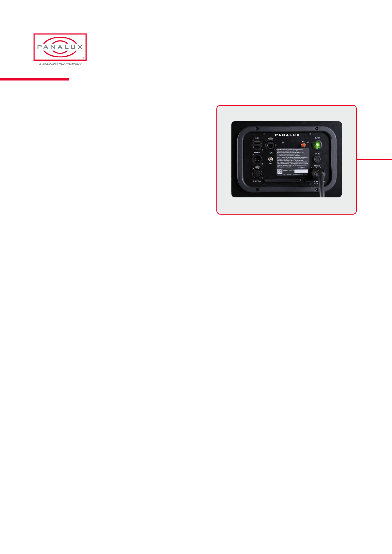
Comms Panel
The comms panel features a power on/off switch as well as
the following connectors: Power in, DMX in, DMX Thru, Art-
Net in RJ45, wireless antenna, 2 x USB, and EXT port.
SONARA™ uses industry standard 5-pin XLR male and
female connectors to receive and output DMX signals. The
DMX wiring is as follows:
Pin 1: Ground
Pin 2: Data +
Pin 3: Data –
Pin 4: Spare
Pin 5: Spare
Please note: SONARA™ is self-terminating and does not
require external DMX termination when used in a chain.
Accessories
SONARA™ has a range of compatible accessories.
Controller extension cord
Power cord
Aerial
M12 eye bolts
Soft Box
Snapgrid
®
Eggcrate
Quarter Grid Cloth
Half Grid Cloth
Full Grid Cloth
Magic Cloth
Weather kit for SONARA
TM
4:4 includes:
Clear vinyl front cover (to be used with soft box)
Rear breathable cover
Comms Panel
PANALUX SONARA USER MANUAL
17 ISSUE 2.5 | MARCH 2024

OPERATION
05
User Interface
SONARA™ provides control over the intensity, colour
temperature, green/magenta bias, hue and saturation,
x y coordinates, amber/lime/blue, and a range of other
parameters for precision control.
Control is via the local user interface on the controller (mounted
to the xture), DMX, Wireless, or Art-Net connection.
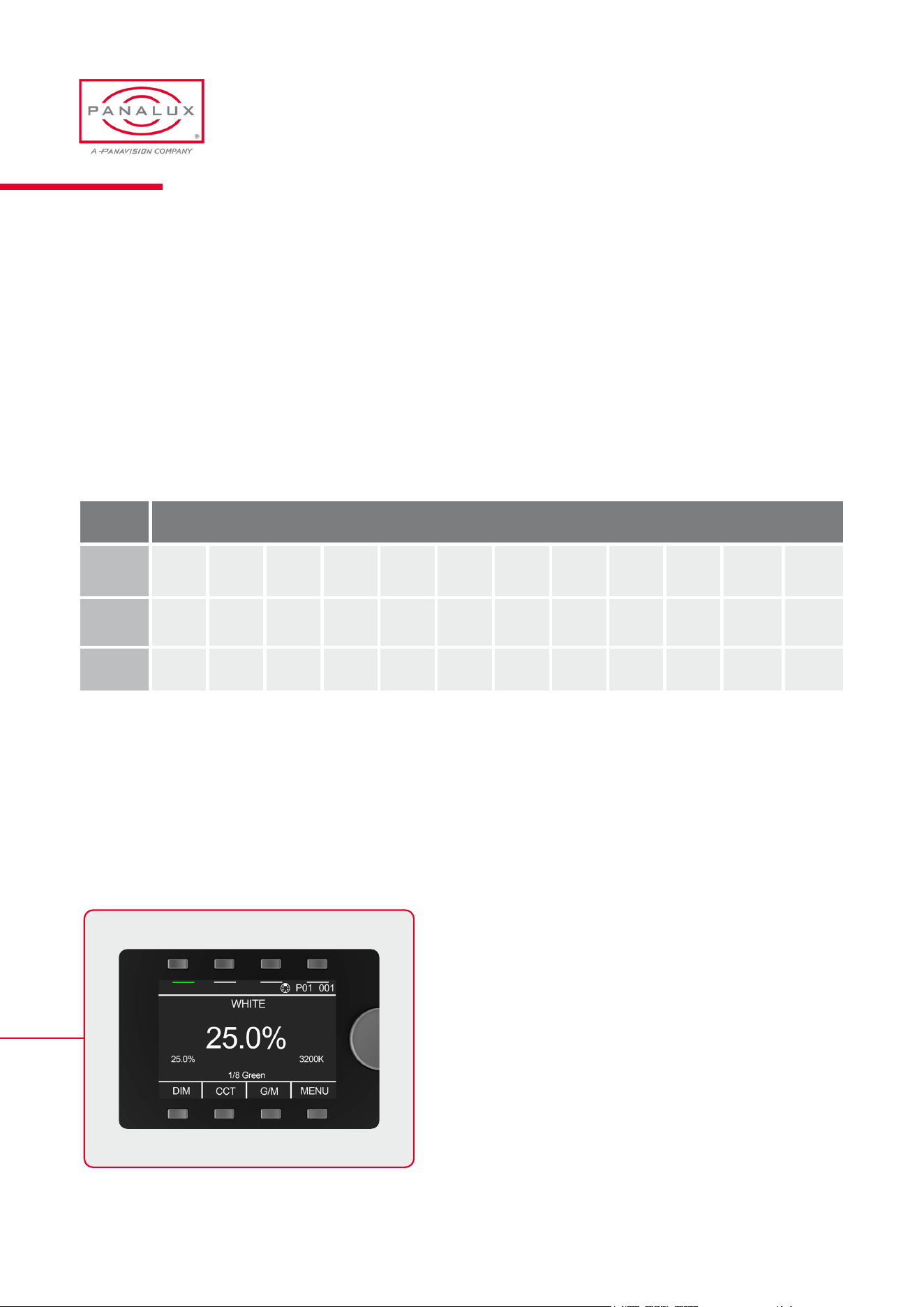
In all modes, the status bar will show the current state of:
DMX Base Address
DMX Personality
DMX Control Source (wired, wireless, Art-Net)
DMX Control Priority (EXT, LTP, LOCAL)
‘LOCKED’(when local control is locked)
‘DEMO’ (when xture is cycling through a demo)
In white mode (shown above), the display will always show:
Dim Position (percentage)
CCT
Green/Magenta Bias
Factory Reset
Factory reset and clearing all memory presets is achieved by holding down the bottom left and bottom right buttons together
while cycling the power.
WARNING.ALLSTOREDPRESETSWILLBEERASED.
User Interface
OPERATION
LockMode
The local controls can be locked and unlocked by holding down the bottom left button for 2 seconds. ‘LOCKED’ will be shown
top centre of the display when local control is disabled.
ToreleaseLOCKEDstatusandDEMOstatus,holddownbottomleftbutton.
PANALUX SONARA USER MANUAL
19 ISSUE 2.5 | MARCH 2024
Rotary Encoder
The encoder enables scrolling forwards or backwards through the ‘live’ highlighted item. Also, by pushing the encoder, you
are able to jump through presets. It is also used to navigate menus.
‘Push’ to conrm selection
See rotary encoder presets below:
After 6 seconds, the encoder always defaults to dimmer in any mode.
The encoder features a ballistic algorithm. The slower it is rotated the higher the resolution. The faster it is rotated the faster it
scrolls through the CCT range or gel.
When controlling the dimming this allows ultra-ne control down to 0.1% steps.
Menu Buttons
There are 4 quick menu buttons below the screen. In WHITE
MODE the rst 3 allow the user to assign the encoder to
alter key attributes: DIM, CCT, and green/magenta bias
(G/M ). The fourth selector button (bottom right) is dedicated
to MENU selection or BACK functions.
Value Presets
Dim 25% 50% 75% 100%
CCT 1600K 2700K 2900K 3200K 3600K 4300K 5000K 5600K 6500K 7500K
10000K 20000K
G/M 1/8 -G 1/4 -G 1/2 -G 3/4 -G 1 -G N/C 1/8 +G 1/4 +G 1/2 +G 3/4 +G 1 +G
User Interface
PANALUX SONARA USER MANUAL
20 ISSUE 2.5 | MARCH 2024
Memory Buttons
The 4 memory buttons above the screen are reserved for memorising and storing 4 unique user dened scenes.
Backlight
The controller screen’s backlight activates on user
interaction, local or from DMX. After 30 seconds of inactivity
it deactivates with a slow fade to 10% brightness.
Controller
Memory Buttons
Menu Buttons
To store a scene, push and hold any button until the screen ashes saved. All scene settings will be saved. For example, in
WHITE MODE, dim percentage, CCT, and green/magenta bias will be saved.
A green bar below a memory button indicates a stored scene. A single button press displays the stored settings without
changing the output, and the bar will turn red. A second press will change the output.
WARNING: The scene memory can be overwritten. Restoring to factory default will permanently erase all user-memory
settings.
PANALUX SONARA USER MANUAL
21 ISSUE 2.5 | MARCH 2024
SONARA™ features ve standard colour selection options:
WHITE
GEL
HSI
ALB
x y
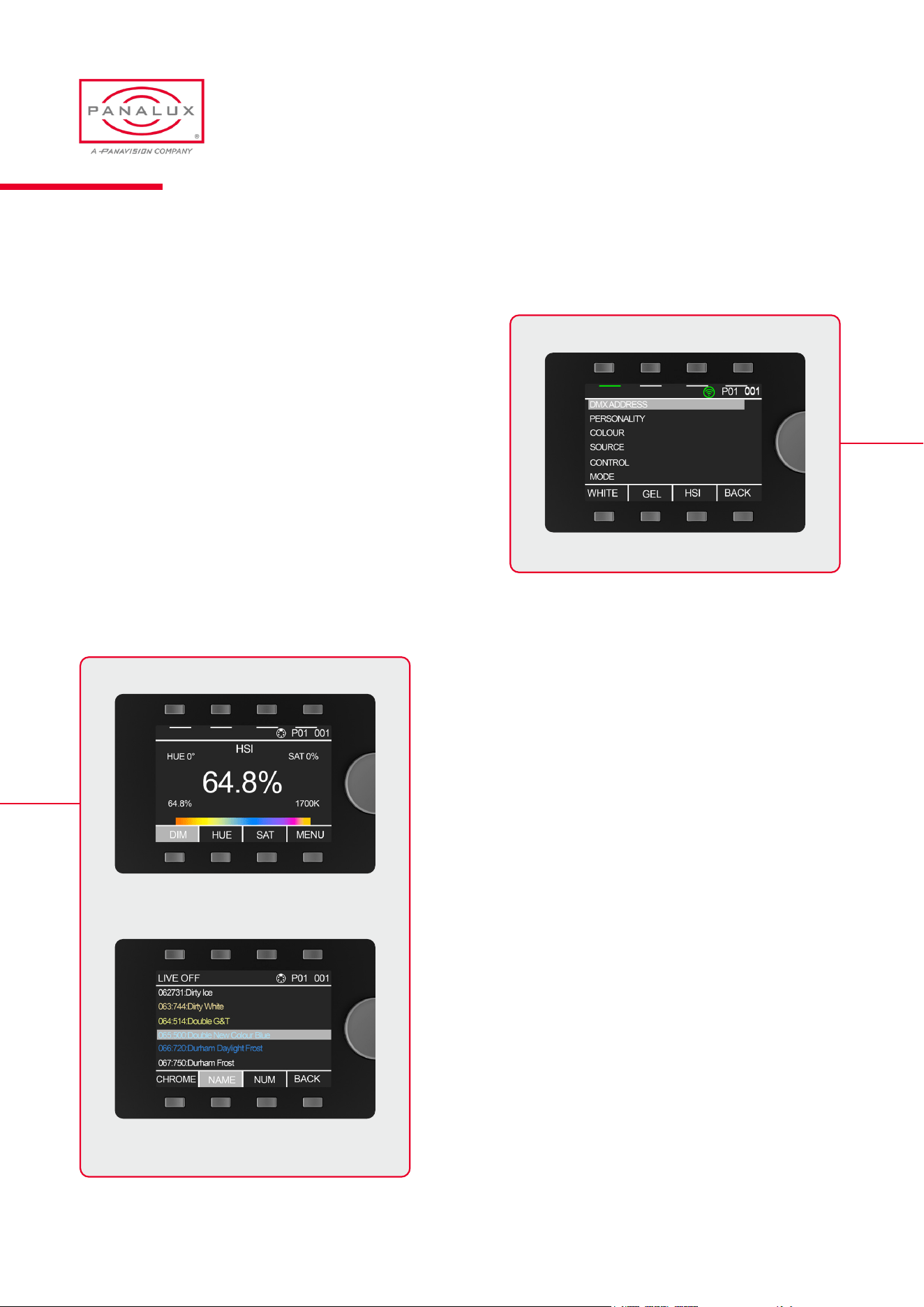
One push of the menu button (bottom right) enables the
menu and shortcuts to:
WHITE,GEL,HSI and BACK
WHITE allows white point control along the Black Body
Locus (BBL) from 1600K – 20,000K and green/magenta
bias above and below the Planckian Locus.
HSI mode allows the user to control the hue angle and
saturation against the set white point.
GEL mode accesses a selection of LEE lter emulations
sortable by chroma, name, and number.
Full gel list in the Appendix (pp. 39-41). Gel numbers
highlighted with a RED background are outside of selected
gamut and are desaturated. See gamut section below.
In this screen, the live highlighted bottom button (NAME
in the top-left example image) allows toggling of LIVE ON
and LIVE OFF. In LIVE OFF mode, you can scroll through a
range of colours without changing the output until selected.
In LIVE ON mode, the output will change actively whilst
scrolling through the gel list.
Menu Screen
HSI Mode
Gel Mode - with Live On/Off
Colours
PANALUX SONARA USER MANUAL
22 ISSUE 2.5 | MARCH 2024
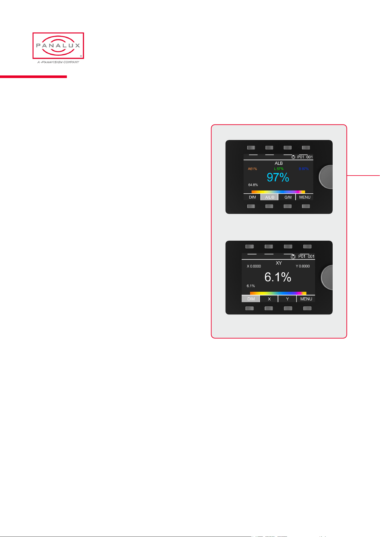
Colours (cont.)
ALB The primary purpose of SONARA™ is to produce high-
quality broad-spectrum whites in an extremely extended range.
ALB (Amber, Lime, Blue) mode is an incomplete colour
wheel.
Repeatedly pressing the ALB button toggles control between
Amber, Lime and Green.
x y mode allows the user to select an x y coordinate on the
CIE 1931 chromaticity chart.
If the chosen colour point is out of gamut, SONARA™ will
shut off its output and the font will turn red.
The light will switch off during adjustment as soon as the
requested coordinate is unachievable. If the coordinates
selected go out of achievable gamut, the coordinate font will
turn red.
ALB Mode
x y Mode
PANALUX SONARA USER MANUAL
23 ISSUE 2.5 | MARCH 2024

CONTROL
FEATURES
& OPTIONS
06
Source
SONARA™ can receive external control from the following sources :
• Wired DMX,
• Wireless DMX with a built-in LumenRadio receiver,
• Art-Net via the RJ45 connector.
• Received DMX is output to the wired DMX socket.
In PRIMARY/CLONE mode, the rst SONARA™ in the DMX chain behaves as primary, with all subsequent SONARA™
in the chain mimicking its settings.
(All SONARA™ in the chain must be set to the same DMX personality.)
Art-Net is used for transmitting DMX lighting control protocol and RDM using the User Datagram Protocol (UDP) of the
Internet Protocol suite. It is used to communicate between nodes/lighting xtures and a lighting desk, typically on a private
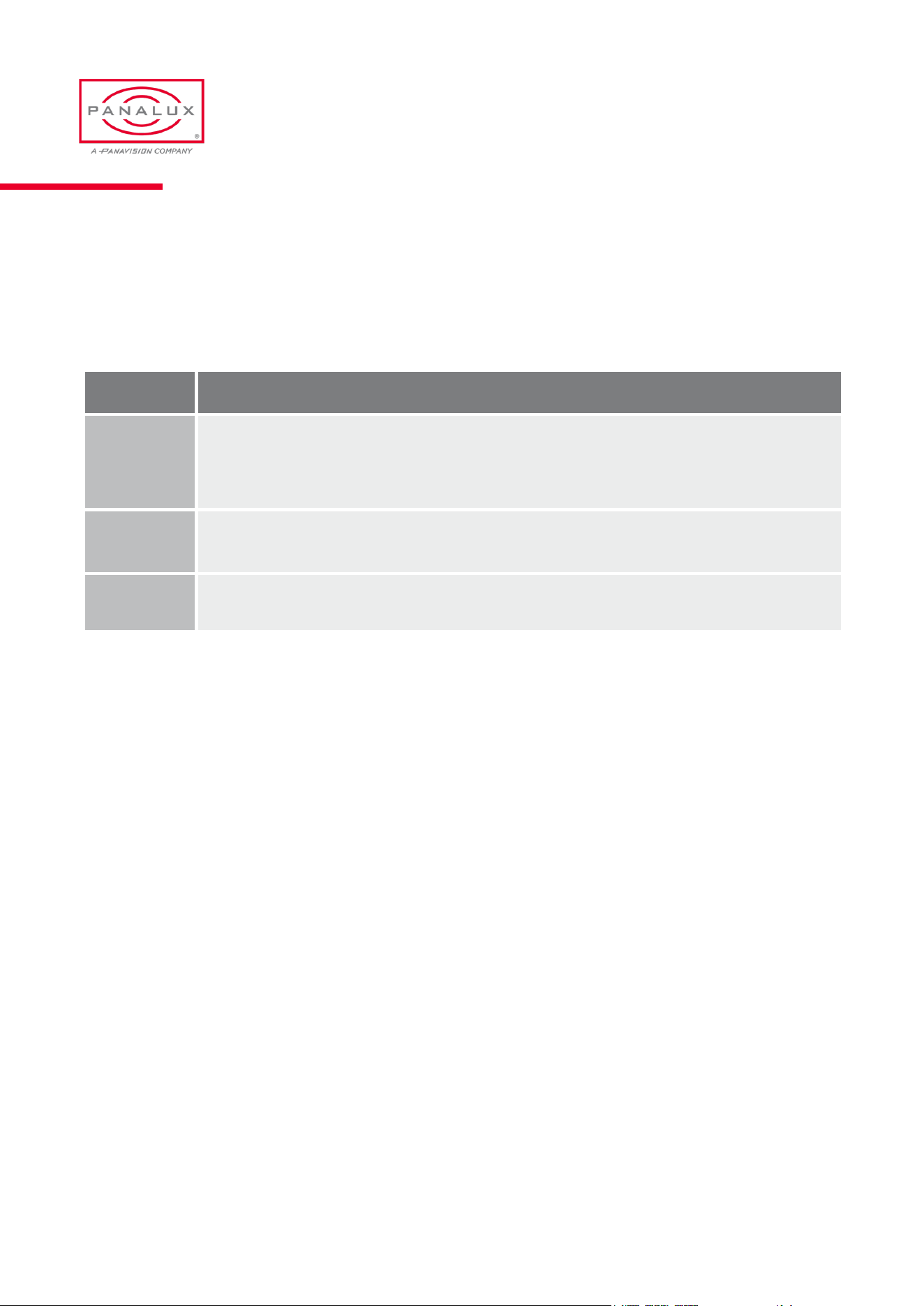
Control / Dimming Curves
SONARA™ has 4 built-in dimming curves:
CONTROL FEATURES & OPTIONS
Curve Characteristics
Linear (Default) In linear mode, 50% equates to half the output, or 1 stop down. 25% is quarter output, or 2 stops down.
SquareLaw
A square law curve increases the dimming resolution at lower control levels.
S Curve
S Curve provides a ner control at lower and higher levels while offering coarse control (lower resolution) at
medium levels. This dimming curve best emulates a typical incandescent lamp’s dimming abilities.
Tungsten Emulate
Tungsten emulate mode combines square law with greater resolution at lower levels and a warming of the
CCT as the xture dims. This operates on any CCT start point between 2700K and 3600K (correlating to an
underrun and overrun tungsten bulb). At CCTs outside this range, standard square law is in play.
PANALUX SONARA USER MANUAL
25 ISSUE 2.5 | MARCH 2024
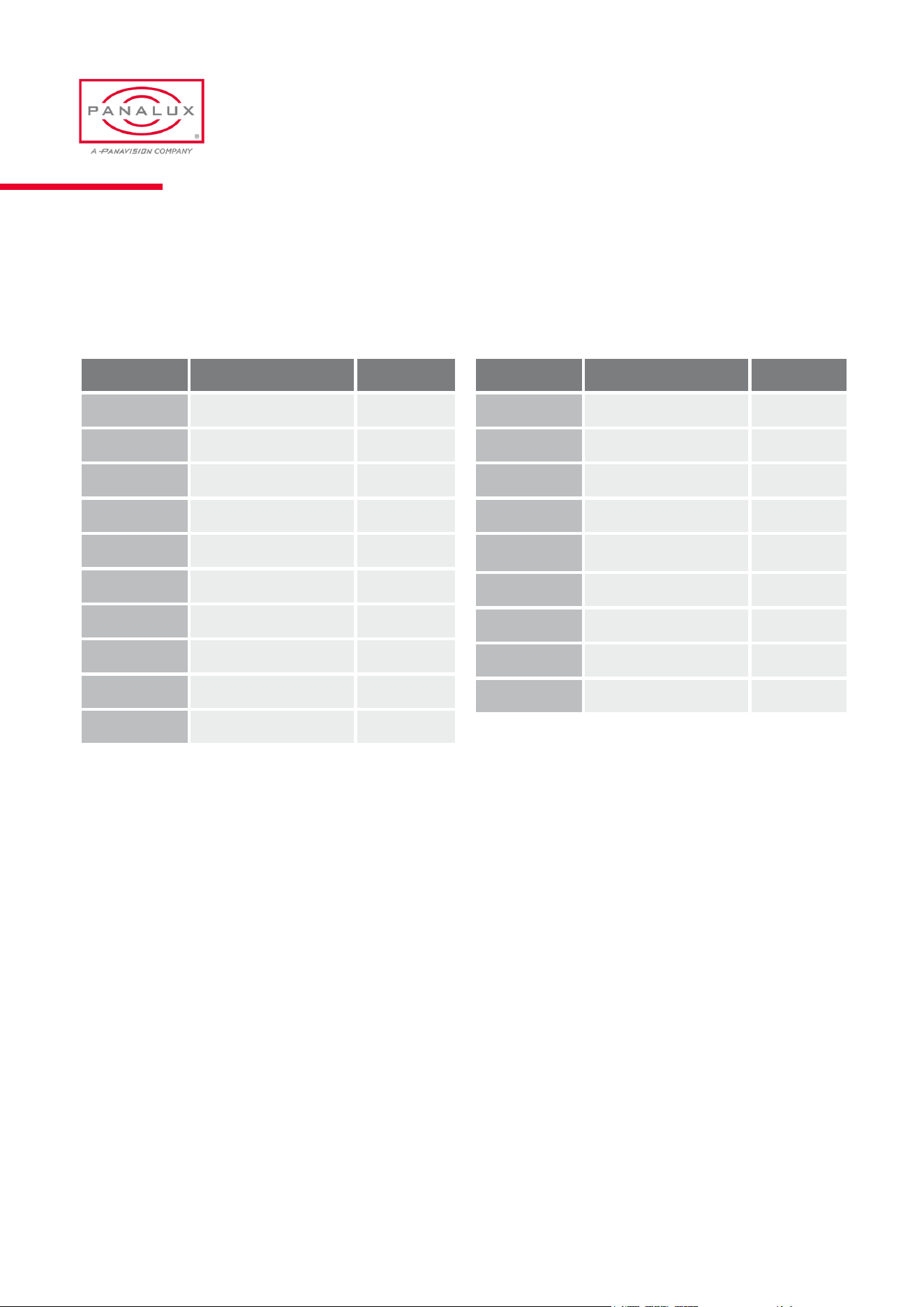
Tungsten Emulate Mode
Tungsten Emulate reference values are as below:
Important Note on Dimming Curves
It is important for consistency that all SONARA™ in a DMX rig are set to the same dimming curve. If set to different dimming
curves, xtures on the same address output won’t track with a global dim command.
Control Output
SONARA™ has two power output modes, BOOST (default) and FLAT. Due to the inherent efcacy difference between
warm white and cold white chips, the photometric output changes at different CCTs. In a studio environment where multiple
changes are made to CCT, it is often advantageous that the photometric output remains constant. This is achieved in FLAT
mode and is active only in WHITE MODE and only between 2700K and 7000K.
In BOOST mode, maximum output is available, which may be advantageous when working in environments with ambient
daylight.
Dim CCT
100% 3200K
85% 3000K
71% 2800K
58%
2600K
48%
2400K
38% 2200K
31% 2000K
Dim CCT
100% 3600K
86% 3400K
74% 3200K
63%
3000K
52%
2800K
35% 2600K
28% 2400K
Dim CCT
100% 2700K
80% 2480K
60% 2220K
40%
1920K
30%
1760K
25% 1695K
10% 1600K
PANALUX SONARA USER MANUAL
26 ISSUE 2.5 | MARCH 2024
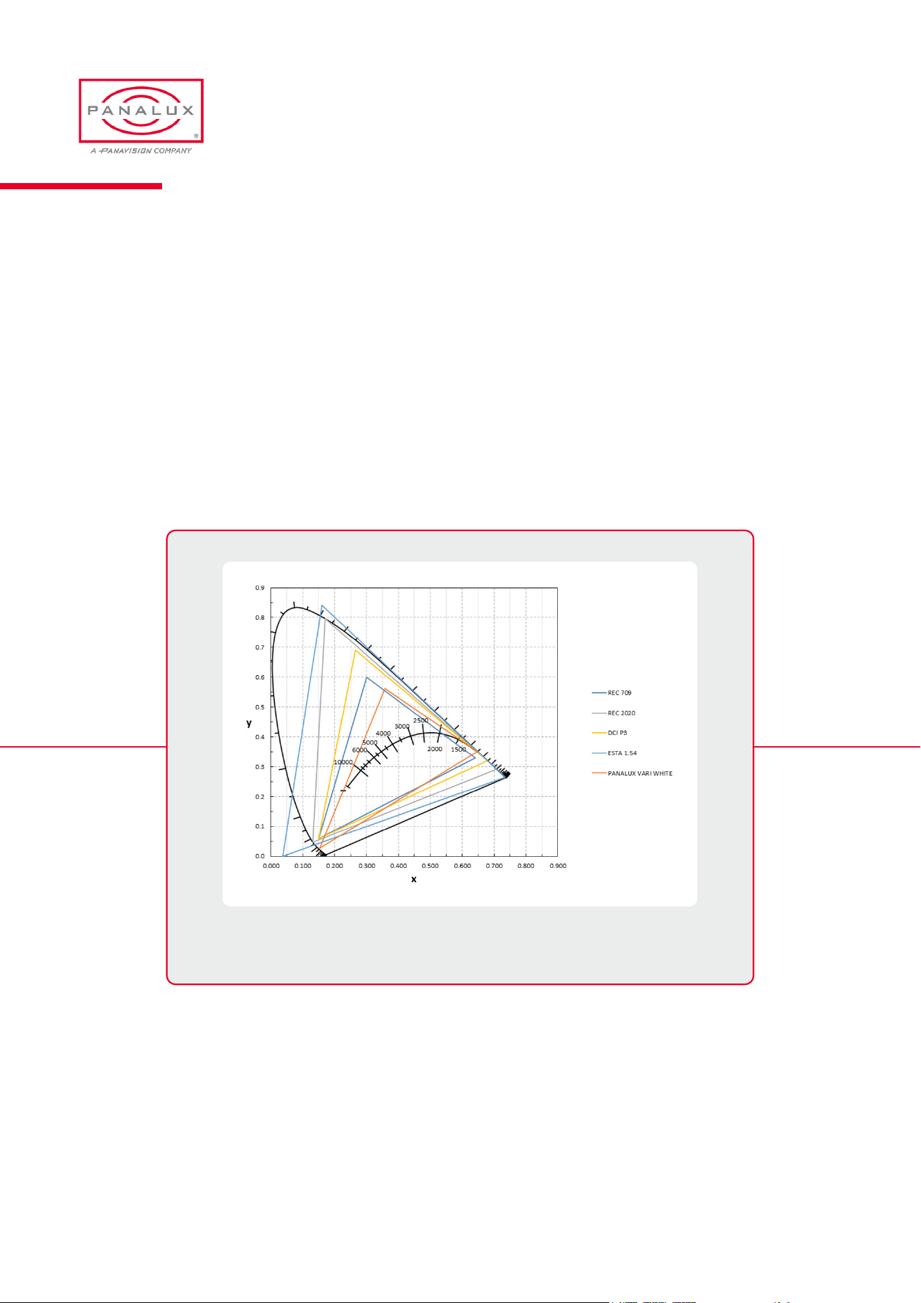
Control Gamut
SONARA™ output gamut can be either full gamut or restricted to match REC 709 or REC 2020. Due to the different overlaps
of the gamuts, selecting REC 709 or REC 2020 will restrict some of SONARA™ output in certain zones. For example, as can
be seen in the illustration below, SONARA™ is capable of producing a range of colours in the yellow and deep amber zone
that wouldn’t be captured in REC 709. In x y mode with REC 709 as the selected gamut, SONARA™ would not output
a colour at those x y coordinates, which would be shown in a red font on the display.
In CCT, HSI, ALB, or GEL mode, if the colour is unachievable due to the chosen gamut, the colour produced will be
desaturated into the selected white point.
ControlCameraLUTs(FutureFeature)
Camera LUTs change both the x y coordinate and spectral mix of whites to match the colour science of various cameras. An
image photographed under the same light source will look different on different cameras. The camera LUTs are intended to
bring alignment to the same subject shot with different cameras.
CIE 1931 Chromaticity Diagram showing gamut comparison between
SO NAR A™ Vari-White and other common colour spaces.
PANALUX SONARA USER MANUAL
27 ISSUE 2.5 | MARCH 2024
Control Priority
SONARA™ can be controlled by local user interface or by external control (wired or wireless).
3 control priority modes are available, detailed below:
Mode Characteristics
LTP (Default)
Last Takes Precedence. In LTP mode, SONARA™ will listen to DMX (wired or wireless), Art-Net, and the local
User Interface, and will take instructions from any. This allows a DOP or gaffer to ‘ride’ the dimmer when the
talent is moving to a cue, or during setup to make changes whilst talking to the board operator, who may be
backstage.
External
Ignores local control and locks the User Interface. To exit this mode, hold down the bottom left button for 5 sec-
onds and the display will go to Control Priority Menu.
Local
Ignores any external input even if wired to DMX.
Modes
SONARA™ features three operating modes:
Standard – Default mode.
Pixilation – Each individual LED panel in the head is addressed separately.
Attract – SONARA™ runs a continuous preset sequence of colours and effects.
To exit this mode, press and hold the bottom left button.
PANALUX SONARA USER MANUAL
28 ISSUE 2.5 | MARCH 2024
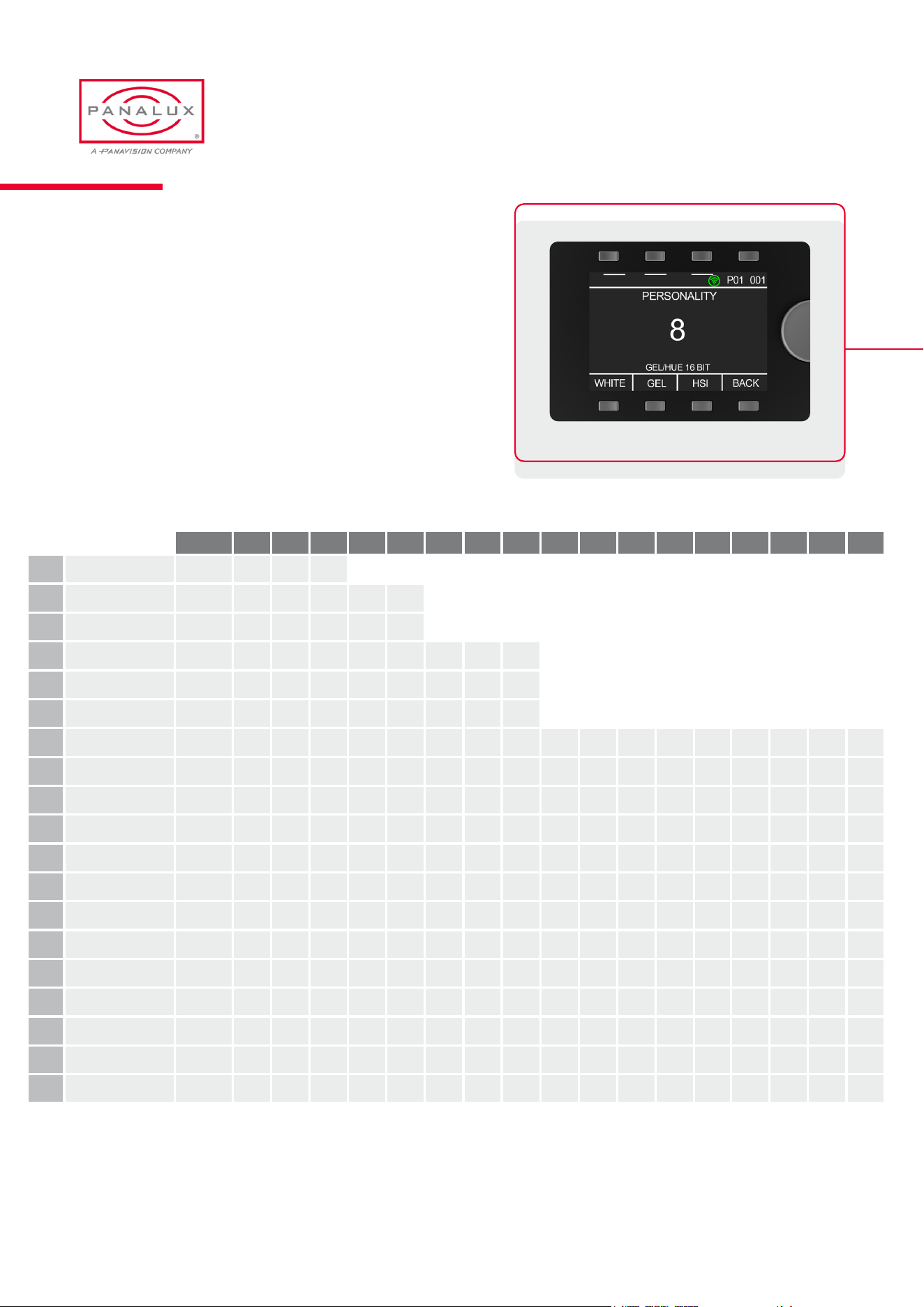
DMX Personalities
DMX personalities determine how SONARA™ behaves in relation to DMX control and the number of channels one xture will
occupy. The selected personality is always shown on the top status bar. SONARA™ has 19 available DMX personalities:
Personality Type Channels
P1 White 8 bit 3
P2 White 16 bit 5
P3 HSI 8 bit 4
P4 HSI 16 bit 8
P5 Gel 24 bit BCD 6
P6 Gel 16 bit 8
P7 Gel Hue 24 bit BCD 9
P8 Gel Hue 16 bit 12
P9 ALB 8 bit 4
P10 ALB 16 bit 8
Personality Type Channels
P11 x y 16 bit 7
P12 x y 24 bit BCD 9
P13 Ultra 7
P14 Extreme 10
P15 Crossfade to colour 9
P16 Crossfade to ALB 8
P17 Crossfade to Gel 11
P18 Crossfade Gel to Gel 17
P19 Crossfade xy to xy 11
DMX Personalities - Channel Assignments
White, HSI and ALB personalities are provided with 8 and 16 bit resolutions.
Gel, Gel hue and xy personalities are provided with 16 bit and 24 bit resolutions.
24 bit assigns one 8 bit channel to each digit of the gel or xy value, allowing easy selection of values with simple desks.
Ultra and Extreme personalities provide direct control over each individual colour in Sonara.
Personalities 15 to 19 provide the ability to cross-fade between a selection of other personalities.
PANALUX SONARA USER MANUAL
29 ISSUE 2.5 | MARCH 2024
DMX Personalities - Channel Assignments
(cont.)
The parameters controlled in each of the DMX
personalities are listed below:
DMX Personality Select
CHANNEL
1 2 3 4 5 6 7 8 9 10 11 12 13 14 15 16 17
P1
WHITE 3
DIM CCT +/-G
P2
16 BIT WHITE 5
DIM DIM CCT CCT +/-G
P3
HSI 8 BIT 4
DIM CCT HUE SAT
P4
HSI 16 BIT 8
DIM DIM CCT CCT HUE HUE SAT SAT
P5
GEL24BITBCD 6
DIM CCT +/-G GEL 000 GEL 00 GEL 0
P6
GEL16BIT 8
DIM DIM CCT CCT +/-G GEL GEL LO-HI
P7
GELHUE24BITBCD 9
DIM CCT +/-G GEL 000 GEL 00 GEL 0 +/- HUE SAT LO-HI
P8
GELHUE16BIT 12
DIM DIM CCT CCT +/-G GEL GEL HUE HUE SAT SAT LO-HI
P9
ALB8BIT 4
DIM AMBER LIME BLUE
P10
ALB16BIT 8
DIM DIM AMBER AMBER LIME LIME BLUE BLUE
P11
x y 16 BIT 7
DIM DIM x x y y
SPEC-
TRAL
BREADTH
P12
x y BCD 9
DIM DIM x .0 x .00 x .000 y .0 y .00 y .000
SPEC-
TRAL
BREADTH
P13
ULTRA 7
DIM DIM AMBER LIME BLUE
WARM
WHITE
COLD
WHITE
P14
EXTREME 10
DIM DIM AMBER 1 AMBER 2 LIME BLUE
WARM
WHITE 1
WARM
WHITE 2
COLD
WHITE 1
COLD
WHITE 2
P15
CROSSFADETOCOLOUR 9
DIM DIM CCT CCT HUE HUE SAT SAT
CROSS-
FADE TO
COLOUR
P16
CROSSFADETOALB 8
DIM DIM CCT CCT AMBER LIME BLUE
CROSS-
FADE TO
ALB
P17
CROSSFADETOGEL 11
DIM DIM CCT CCT GEL GEL HUE HUE SAT SAT
CROSS-
FADE TO
GEL
P18
CROSSFADEGELTOGEL 17
DIM DIM CCT CCT GEL A GEL A HUE A HUE A SAT A SAT A GEL B GEL B HUE B HUE B SAT B SAT B
CROSS-
FADE GEL
TO GEL
P19
CROSSFADE X Y TO X Y 11
DIM DIM x A x A y A y A x B x B y B y B
CROSS-
FADE xy
TO xy
PANALUX SONARA USER MANUAL
30 ISSUE 2.5 | MARCH 2024
SONARA™ is RDM Enabled
RDM functionality gives the ability to remotely identify the xture, set its DMX address and DMX personality, and other
options. This feature also enables information about SONARA to be read remotely, such as the temperature of the LED
arrays. See the full list of RDM functions and monitoring options below:
RDM
Function Type
1 UID (Unique Identier) to allow recognition of individual xtures Monitoring
2 RDM Protocol Version Monitoring
3 Device Model Description Fixed
4 Manufacturer Label Fixed
5 Software Version Fixed
6 Serial Number Fixed
7 DMX Footprint Monitoring
8 DMX Personality Description Monitoring
9 DMX Start Address User Editable
10 DMX Personality User Editable
11 Dimming Curve User Editable
12 Output Mode User Editable
13 Colour Gamut User Editable
14 Camera LUT User Editable
15 Device Hours Monitoring
16 Lamp Hours Monitoring
17 Power Output Monitoring
18 Reset device to factory defaults and wipe saved scenes User Editable
PANALUX SONARA USER MANUAL
31 ISSUE 2.5 | MARCH 2024
SONARA RDM Sensors
See the full list of remote sensor monitoring options below:
Sensor Type Reading
1 Temperature Array temperature in degrees Celsius
2 Temperature Array temperature in degrees Celsius
3 Temperature Array temperature in degrees Celsius
4 Temperature Array temperature in degrees Celsius
5 Temperature Array temperature in degrees Celsius
6 Temperature Array temperature in degrees Celsius
7 Temperature Array temperature in degrees Celsius
8 Temperature Array temperature in degrees Celsius
9 Temperature Array temperature in degrees Celsius
10 Temperature Array temperature in degrees Celsius
11 Temperature Array temperature in degrees Celsius
12 Temperature Array temperature in degrees Celsius
13 Temperature Array temperature in degrees Celsius
14 Temperature Array temperature in degrees Celsius
15 Temperature Array temperature in degrees Celsius
16 Temperature Array temperature in degrees Celsius
17 Temperature Master driver processor temperature in degrees Celsius
PANALUX SONARA USER MANUAL
32 ISSUE 2.5 | MARCH 2024
SONARA Menu Tree
DMX ADDRESS 1 - 512
PERSONALITY 1 - 19
COLOUR
WHITE
GEL
HSI
ALB
X Y
SOURCE
WIRED
WIRELESS
ARTNET
PRIMARY/CLONE
MODE
STANDARD
PIXILATION
ATTRACT
CONTROL
CURVES
LINEAR
SQUARE LAW
S CURVE
TUNGSTEN EMULATE
OUTPUT
BOOST
FLAT
GAMUT
PX VARI WHITE
REC 2020
REC 709
DCI P3
ESTA 1.54
CONTROL PRIORITY
LTP
EXTERNAL
LOCAL
PANALUX SONARA USER MANUAL
33 ISSUE 2.5 | MARCH 2024

GENERAL
07
General Information
Power Characteristics
Physical Characteristics
Characteristic SONARA
TM
4:4 SONARA
TM
3:2 SONARA
TM
4:1
AC power / nominal input
voltage
110-240V (AC) 50-60Hz 110-240V (AC) 50-60Hz 110-240V (AC) 50-60Hz
Max input current 14A (110V) / 7A (230V) 6A (110V) / 3A (230V) 6A (110V) / 3A (230V)
Max power input 1500W 500W 350W
Characteristic SONARA
TM
4:4 SONARA
TM
3:2 SONARA
TM
4:1
Dimensions (excluding
yoke)
1248 x 1248 x 134 (mm)
49 x 49 x 5.25 (inches)
648 x 948 x 134 (mm)
25.5 x 37 x 5.25 (inches)
1248 x 348 x 134 (mm)
49 x 13.7 x 5.25 (inches)
Dimensions (including
yoke)
1486 x 1546 x 163 (mm)
58.5 x 61 x 6.5 (inches)
1097 x 1001 x 152 (mm)
43.2 x 39.4 x 6 (inches)
1370 x 646 x 134 (mm)
54 x 25.5 x 5.25 (inches)
Weight (excluding
accessories)
44kg 25kg 18.5kg
Weight (excluding yoke) 38kg 19kg 13.5kg
PANALUX SONARA USER MANUAL
35 ISSUE 2.5 | MARCH 2024
Fault Finding Tips
Issue Possible Solution
No power seen and rocker switch not lit Fuse in fuse holder blown. Try replacement
No response from controller on power up or splash screen
Conrmthatthecontrollerislocatedrmlyandsquarely
in the holder and held by the magnets. Check to see if
thelanyardishinderingthecontroller’spositioning.
No response from controller in remote mode
Conrmthatbothendsofthecablearettedcorrectly
into the housings on the head and the controller and that
the keyway aligns.
Two or more xtures on the same address are behaving
differently on dimming or CCT
Ensurethatallxturesaresetinthesameoptionfor
personality,dimmingcurve,andFLAT/BOOST.
One or more xtures on a DMX Universe are ashing or
behaving oddly
ConrmthatnoneofthexturesareinPRIMARY/
CLONEmode.
PANALUX SONARA USER MANUAL
36 ISSUE 2.5 | MARCH 2024
SONARA
TM
4:4 Optical Characteristics
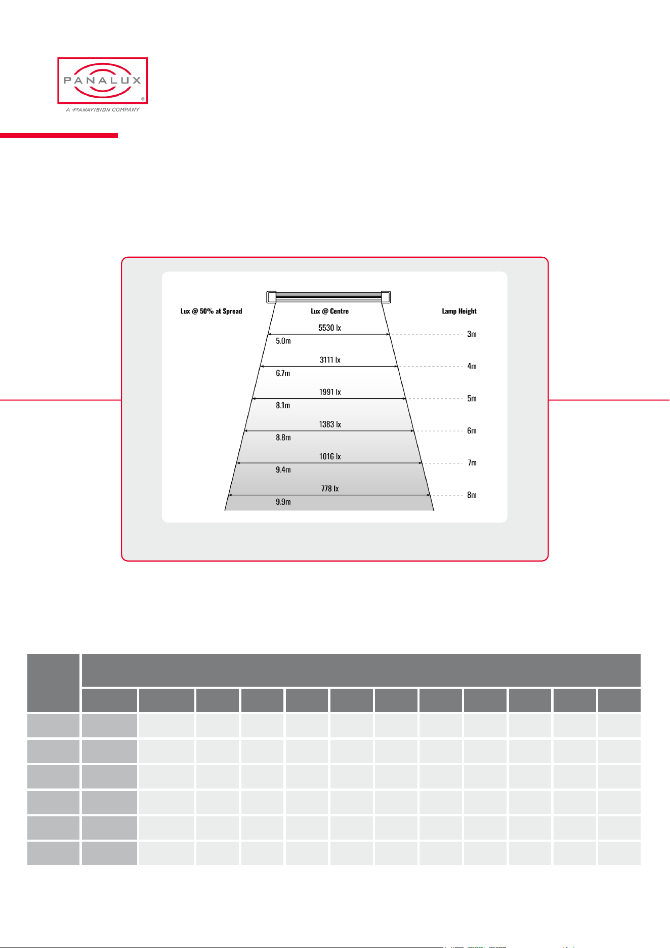
The waterfall diagram shows a typical spread of light when SONARA™ 4:4 is suspended at various heights.
Measurements were taken with a temperature stabilised SONARA™ 4:4 set at 4300K at maximum intensity.
SONARA
TM
4:4LuxVariationwithHeightandSpread
Further detailed measurements listed below were taken with a SONARA™ 4:4 at 4300K as above.
SO NAR A™ 4:4 Luminous Intensity
Height
(m)
Lux(lx)variationwithheight(m)anddiameter(m)
Spread Centre 1.2 2.4 3.7 4.9 6.1 7. 3 8.5 9.8 11.0 12.2
3 5.0 5533 4682 4128 3575 2724 2128 1575 1192 894 724 553
4 6.7 3111 2636 2332 2028 1553 1220 906 689 518 421 322
5 8.1 1991 1701 1539 1384 1102 899 694 545 423 352 276
6 8.8 1383 1186 1088 997 813 681 539 435 345 293 234
7 9.4 1026 874 808 750 620 529 427 351 283 245 199
8 9.9 778 670 623 583 487 421 344 287 235 206 169
PANALUX SONARA USER MANUAL
37 ISSUE 2.5 | MARCH 2024

This page intentionally left blank.
PANALUX SONARA USER MANUAL
38 ISSUE 2.5 | MARCH 2024
This page intentionally left blank.
PANALUX SONARA USER MANUAL
39 ISSUE 2.5 | MARCH 2024
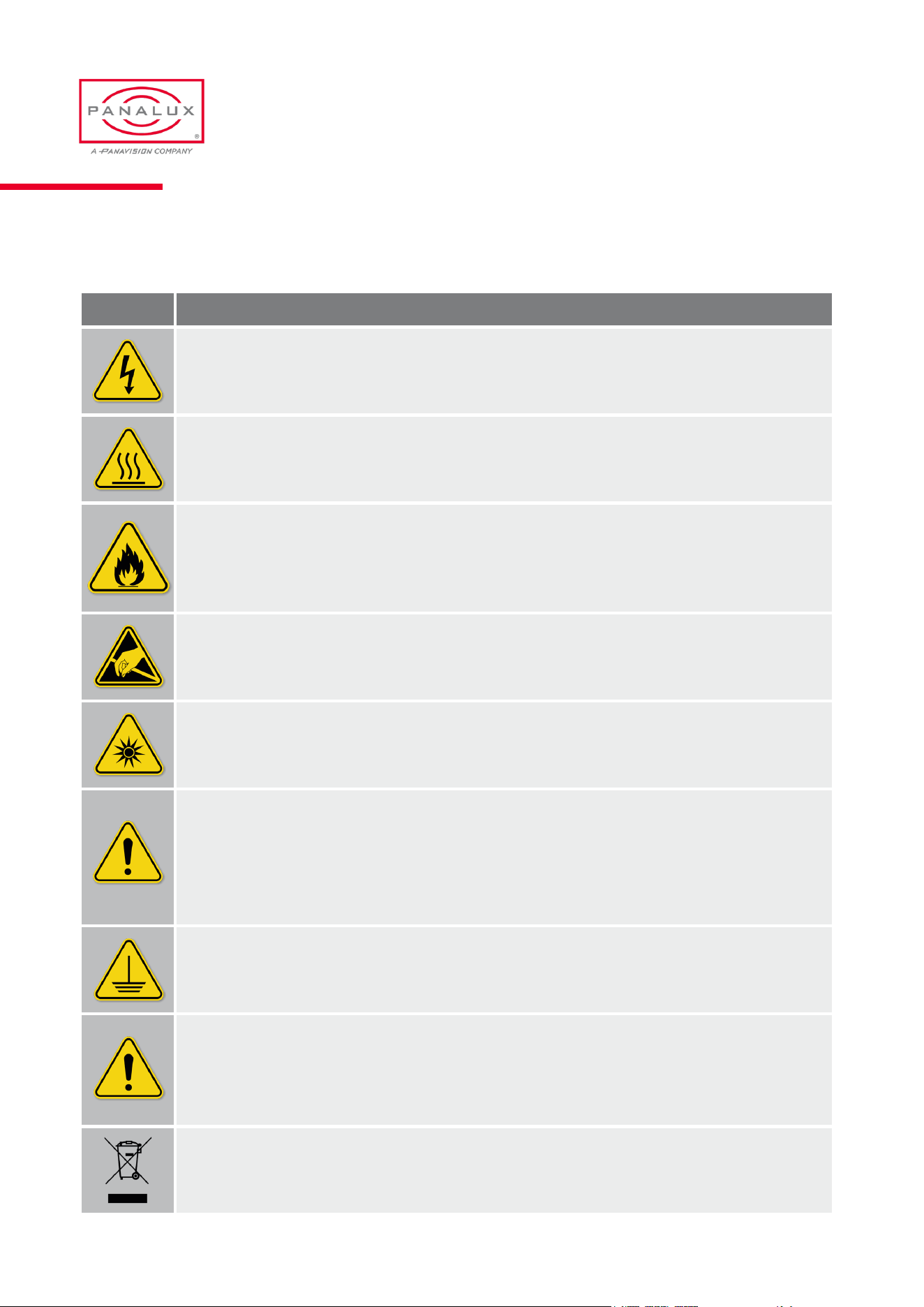
Warnings & Cautions
SYMBOL MEANING
Riskofelectricshock/riskofre
Do not open. To reduce the risk of electric shock, do not remove cover (or back). No user serviceable parts
inside. Refer servicing to qualied service personnel.
Burning Injuries
Be aware of high case temperatures of 60-85°C during and after use of SONARA™. Don’t touch the metal
cases, frames or LED’s to avoid burning issues.
Flammable Materials
Keep ammable materials away from the installation. The installation should be such that the amount of air ow
required for safe operation of the equipment is not compromised. Proper ventilation must be provided.
ESDandLEDs
LED components used in SONARA™ are sensitive to electro-static discharge (ESD). To prevent the possibility
of destroying LED components do not touch during operation or when SONARA™ is switched off.
Lightoutput
Due to high light-output intensity do not look directly into the bare LED array. Use diffusers when exposing the
light to human eyes.
Disconnect Device
When the appliance inlets of any individual SONARA™ are not accessible, the socket outlets supplying the
rack shall be installed near the equipment and be easily accessible, or a readily accessible general disconnect
device shall be incorporated in the xed wiring. Disconnect device should state 3mm separation in both poles
and should include reference to national wiring rules.
This equipment MUST be earthed
In order to protect against risk of electric shock, the installation should be properly grounded. Defeating the
purpose of the grounding type plug will expose you to the risk of electric shock.
Mains cords
Use only a Neutrik PowerCon TrueOne NAC3FX-W-TOP Connector. The user is responsible for ensuring power
cables are of adequate condition for each application. If the power cords are damaged, replace them only with
new ones. Never try to repair a power cord.
Environmental: Disposal of old electrical & electronic equipment
This symbol on the product or on its packaging indicates that this product shall not be treated as
household waste.
PANALUX SONARA USER MANUAL
40 ISSUE 2.5 | MARCH 2024
Spare Parts & Accessories
Description SONARA
TM
4:4 SONARA
TM
3:2 SONARA
TM
4:1
Lamphead HIN98AR HINWIAR HIO8QAR
Yoke JINKBAR JIO1FAR JIO8RAR
Lockinghandle GN.15633 GN.15633 GN.15633
Eye bolt JINKOAR JINKOAR JINKOAR
Controller JIN9LAR JIN9LAR JIN9LAR
Controller extension cable CIN9MAR CIN9MAR CIN9MAR
Controller extension cable pouch YINBOAR YINBOAR YINBOAR
Aerial HINXFAR HINXFAR HINXFAR
Power cord VIKLIA7 VIKLIA7 VIKLIA7
Soft box JIN9OAR JIO0RAR
Soft box bag YIN9PAR YIO0SAR
Full Grid Cloth JIN9RAR JIO0UAR
Half Grid Cloth JIN9SAR JIO0VAR
Quarter Grid Cloth JIN9TAR JIO0WAR
Magic Cloth JIN9QAR JIO0TAR
Egg crate GJNBPAJ GJO1HAJ
Egg crate bag YJNBQAJ YJO1IAJ
Rain cover – front JINR8AR
Raincover–rear(at) JINR9AR
Rain cover – rear (domed) JINRAAR
PANALUX SONARA USER MANUAL
41 ISSUE 2.5 | MARCH 2024

APPENDIX
08
GelLibrary
Gel Name
2 Rose Pink
3 Lavender Tint
4 Medium Bastard Amber
7 Pale Yellow
8 Dark Salmon
9 Pale Amber Gold
10 Medium Yellow
13 Straw Tint
15 Deep Straw
17 Surprise Peach
19 Fire
20 Medium Amber
21 Gold Amber
22 Dark Amber
24 Scarlet
25 Sunset Red
26 Bright Red
27 Medium Red
29 Plasa Red
35 Light Pink
36 Medium Pink
46 Dark Magenta
48 Rose Purple
49 Medium Purple
52 Light Lavender
53 Paler Lavender
58 Lavender
61 Mist Blue
63 Pale Blue
68 Sky Blue
71 Tokyo Blue
75 Evening Blue
79 Just Blue
85 Deeper Blue
88 Lime Green
89 Moss Green
90 Dark Yellow Green
100 Spring Yellow
101 Yellow
102 Light Amber
103 Straw
104 Deep Amber
105 Orange
106 Primary Red
107 Light Rose
108 English Rose
109 Light Salmon
110 Middle Rose
111 Dark Pink
113 Magenta
115 Peacock Blue
116 Medium Blue-Green
117 Steel Blue
118 Light Blue
119 Dark Blue
120 Deep Blue
121 LEE Green
122 Fern Green
124 Dark Green
126 Mauve
127 Smokey Pink
128 Bright Pink
130 Clear
131 Marine Blue
132 Medium Blue
134 Golden Amber
135 Deep Golden Amber
136 Pale Lavender
137 Special Lavender
138 Pale Green
139 Primary Green
140 Summer Blue
141 Bright Blue
142 Pale Violet
143 Pale Navy Blue
144 No Colour Blue
147 Apricot
PANALUX SONARA USER MANUAL
43 ISSUE 2.5 | MARCH 2024

188 Cosmetic Highlight
189 Cosmetic Silver Moss
191 Cosmetic Aqua Blue
192 Flesh Pink
194 Surprise Pink
195 Zenith Blue
196 True Blue
197 Alice Blue
198 Palace Blue
199 Regal Blue
200 Double C.T. Blue
201 Full C.T. Blue
202 Half C.T. Blue
203 Quarter C.T. Blue
204 Full C.T. Orange
205 Half C.T. Orange
206 Quarter C.T. Orange
207 Full C.T. Orange + .3 ND
208 Full C.T. Orange + .6 ND
212 L.C.T.Yell o w ( Y1)
213 White Flame Green
217 Blue Diffusion
218 Eighth C.T. Blue
219 LEE Fluorescent Green
221 Blue Frost
GelLibrary(cont.)
148 Bright Rose
151 Gold Tint
152 Pale Gold
153 Pale Salmon
154 Pale Rose
156 Chocolate
157 Pink
158 Deep Orange
159 No Colour Straw
161 Slate Blue
162 Bastard Amber
164 Flame Red
165 Daylight Blue
169 Lilac Tint
170 Deep Lavender
172 Lagoon Blue
174 Dark Steel Blue
176 Loving Amber
179 Chrome Orange
180 Dark Lavender
181 Congo Blue
182 Light Red
183 Moonlight Blue
184 Cosmetic Peach
186 Cosmetic Silver Rose
187 Cosmetic Rouge
223 Eighth C.T. Orange
224 Daylight Blue Frost
225 Neutral Density Frost
230 Super Correction L.C.T.
232 Super Correction W.F.
236 H.M.I. (to Tungsten)
237 C.I.D. (to Tungsten)
238 C.S.I. (to Tungsten)
241
LEE Fluorescent 5700
Kelvin
242
LEE Fluorescent 4300
Kelvin
243
LEE Fluorescent 3600
Kelvin
244 LEE Plus Green
245 Half Plus Green
246 Quarter Plus Green
247 LEE Minus Green
248 Half Minus Green
249 Quarter Minus Green
278 Eighth Plus Green
279 Eighth Minus Green
281 Three Quarter C.T. Blue
283 One and a Half C.T. Blue
285
Three Quarter C.T.
Orange
286
One and a Half C.T.
Orange
PANALUX SONARA USER MANUAL
44 ISSUE 2.5 | MARCH 2024
287 Double C.T. Orange
322 Soft Green
323 Jade
327 Forest Green
328 Follies Pink
332 Special Rose Pink
343
Special Medium Lav-
ender
345 Fuchsia Pink
352 Glacier Blue
353 Lighter Blue
354 Special Steel Blue
363 Special Medium Blue
366 Cornower
441 Full C.T. Straw
442 Half C.T. Straw
443 Quarter C.T. Straw
444 Eighth C.T. Straw
500 Double New Colour Blue
501
New Colour Blue (Rob-
ertson Blue)
502 Half New Colour Blue
503 Quarter New Colour Blue
504 Waterfront Green
505 Sally Green
506 Marlene
507 Madge
GelLibrary(cont.)
508 Midnight Maya
511 Bacon Brown
512 Amber Delight
513 Ice and a Slice
514 Double G&T
525 Argent Blue
550 ALD Gold
600 Arctic White
601 Silver
602 Platinum
603 Moonlight White
604 Full C.T. Eight Five
642 Half Mustard Yellow
643 Quarter Mustard Yellow
650 Industry Sodium
651 HI Sodium
652 Urban Sodium
653 LO Sodium
700 Perfect Lavender
701 Provence
702 Special Pale Lavender
703 Cold Lavender
704 Lily
705 Lily Frost
706 King Fals Lavender
707 Ultimate Violet
708 Cool Lavender
709 Electric Lilac
710 Spir Special Blue
711 Cold Blue
712 Bedford Blue
713 J.Winter Blue
714 Elysian Blue
715 Cabana Blue
716 Mikkel Blue
717 Shanklin Frost
718 Half Shanklin Frost
719 Colour Wash Blue
720 Durham Daylight Frost
721 Berry Blue
722 Bray Blue
723 Virgin Blue
724 Ocean Blue
725 Old Steel Blue
727 QFD Blue
728 Steel Green
729 Scuba Blue
730 Liberty Green
731 Dirty Ice
733 Damp Squib
735 Velvet Green
736 Twickenham Green
PANALUX SONARA USER MANUAL
45 ISSUE 2.5 | MARCH 2024
738 JAS Green
740 Aurora Borealis Green
741 Mustard Yellow
742 Bram Brown
744 Dirty White
746 Brown
747 Easy White
748 Seedy Pink
749 Hampshire Rose
763 Wheat
764 Sun Colour Straw
765 LEE Yellow
767 Oklahoma Yellow
768 Egg Yolk Yellow
770 Burnt Yellow
773 Cardbox Amber
774 Soft Amber Key 1
775 Soft Amber Key 2
776 Nectarine
777 Rust
778 Millennium Gold
779 Bastard Pink
780 AS Golden Amber
781 Terr y Red
787 Marius Red
GelLibrary(cont.)
789 Blood Red
790 Moroccan Pink
791 Moroccan Frost
793 Vanity Fair
794 Pretty 'n Pink
795 Magical Magenta
797 Deep Purple
798 Chrysalis Pink
799 Special KH Lavender
801 Zircon Minus Green 1
802 Zircon Minus Green 2
803 Zircon Minus Green 3
804 Zircon Minus Green 4
805 Zircon Minus Green 5
806 Zircon Warm Amber 2
807 Zircon Warm Amber 4
808 Zircon Warm Amber 6
809 Zircon Warm Amber 8
810 Zircon Diffusion 1
811 Zircon Diffusion 2
812 Zircon Diffusion 3
813 Zircon Warm Amber 5
814 Zircon Warm Amber 9
815 Zircon Dark Density
816 Zircon Mid Density
817 Zircon Pale Density
818 Zircon Cool Blue 6
819 Zircon Cool Blue 8
820 Zircon Cool Blue 10
840 Special Cyan 15
841 Special Cyan 30
842 Special Cyan 60
850 Panalux Inky Blue
851 Panalux Full Amber
852 Panalux Phosphor Green
855 Panalux Midnight Layla
856 Panalux Backlight Blue
857 Panalux Deep Congo
858 Panalux Neon Pink
859 Panalux Salty Dog Sea
860 Panalux Lush Lavender
861 Panalux Deepest violet
PANALUX SONARA USER MANUAL
46 ISSUE 2.5 | MARCH 2024
900 SM - Candle ame 1700K
901 SM - Candle ame 1850K
902
SM - High Quality Filament style
domestic Tungsten LED
903
904 SM - Carbon arc
905 SM - Low pressure sodium
906 SM - Sodium vapour
907
SM - High Pressure sodium -
stadium lighting
908 SM - Mercury vapour
909 SM - Xenon
910 SM - Arena lighting
911 SM - Frosty night
912 SM - Val d'isere
913 SM - Watery winter sunlight
914 SM - Shadow side winter sun
915
SM - Overcast winter dusk no
sun
916
917
SM - Sunlight - 5790K - clear
blue sky - midsummer
918 SM - Electronic ash
919
920 SM - Flourescent warm white
921 SM - Flourescent neutral white
922 SM - Flourescent cold white
923 SM - Flourescent old green
924 SM - Halophosphate orescent
925 SM - Auto Xenon headlamp
926
SM - Auto Old style sealed
beam headlamp
927
SM - Auto Indicator lamp
(modern)
928
SM - Auto Indicator lamp
(classic)
929 SM - Auto side light (classic)
930
931
932
933
934
935
SM - Green screen (narrow
band)
936 SM - Blue screen (narrow band)
937 SM - Green screen (power)
938 SM - Blue screen (power)
939
940
SourceEmulationList
PANALUX SONARA USER MANUAL
47 ISSUE 2.5 | MARCH 2024
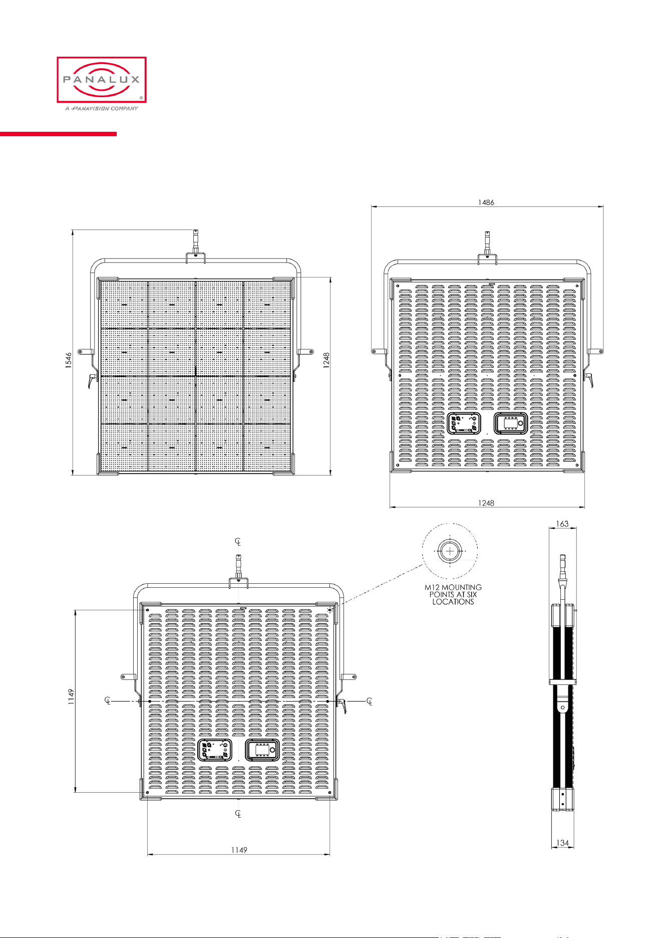
SONARA
TM
4:4 Overall Dimensions & Rigging Centres
PANALUX SONARA USER MANUAL
48 ISSUE 2.5 | MARCH 2024
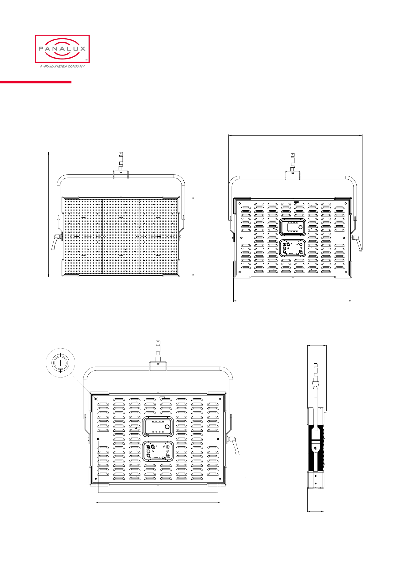
SONARA
TM
3:2 Overall Dimensions & Rigging Centres
549
849
821
M12 MOUNTING
POINTS AT SIX
LOCATIONS
1069
948
134
151
1001
648
1069
948 134
151
1001
648
1069
948
134
151
1001
648
PANALUX SONARA USER MANUAL
49 ISSUE 2.5 | MARCH 2024
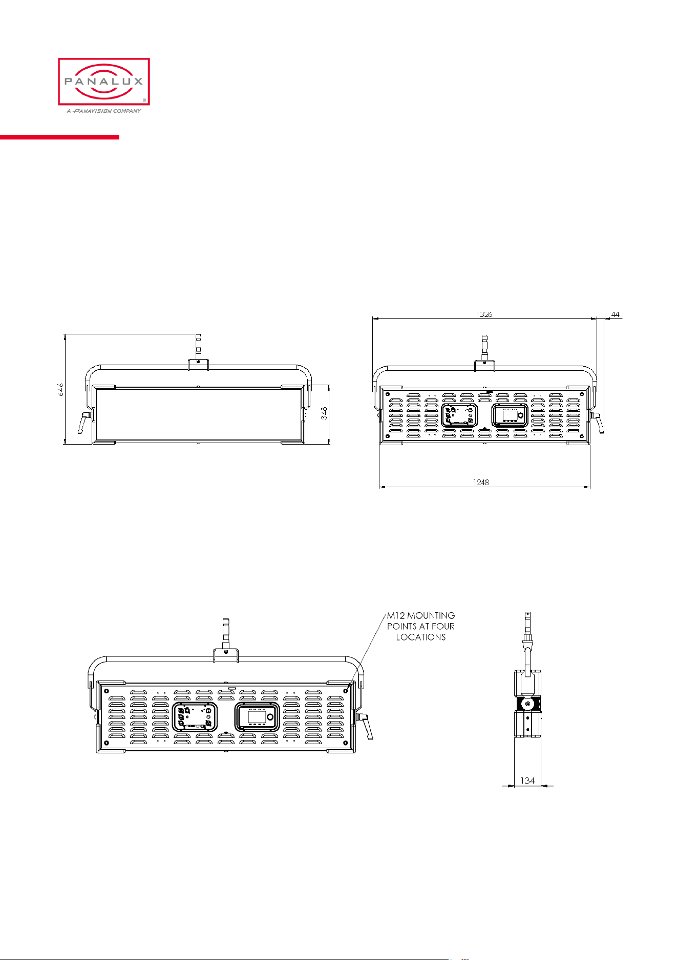
SONARA
TM
4:1 Overall Dimensions & Rigging Centres
PANALUX SONARA USER MANUAL
50 ISSUE 2.5 | MARCH 2024