❶ ❷ ❸
User Manual
EC-680Automotive Paint Meter
V1.0.2
1. Introduction
This instrument can non-destructively measure the thickness of non-
conductive coatings on metal surfaces, as well as the thickness of non-
ferritic metal coatings on ferromagnetic metals (such as iron, nickel, and
cobalt). Specific applications include measuring the thickness of paint or
galvanized coatings on iron, martensitic stainless steel surfaces, as well as
the thickness of paint or plastic films on aluminum and copper surfaces.
This instrument is designed for vehicle paint inspection. It can
measure paint thickness while simultaneously identifying materials such
as iron galvanized and iron powder paste. The device exhibits strong
interference resistance and operates normally in complex electromagnetic
field environments.
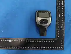
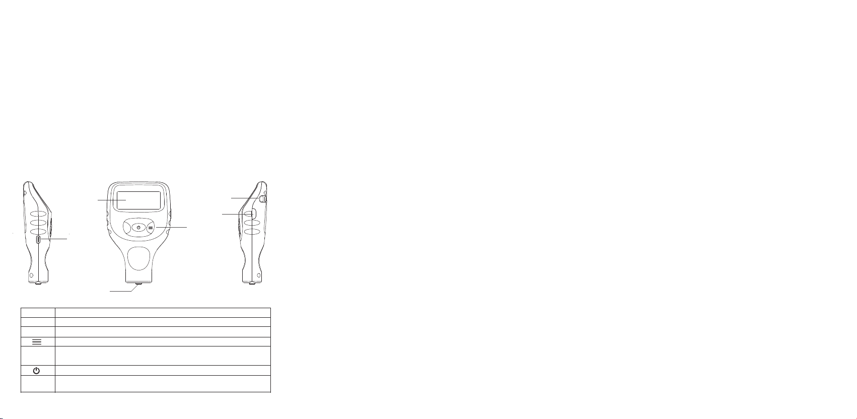
2. Schematic diagram of appearance
Display screen
Hanging rope
hole
Button area
Probe
USB port
Key Instructions
Key
Function
Up key: Turn page up; Switch options
Down key: Turn page down; Switch options
Menu key: Open menu; Confirm
Backkey:Gobacktothepreviouspageanddeletethelatest
data
Power key: Power on/off; Zero calibration
Side
button
Short press to rotate the screen; long press to switch display
styles
Side button
﹀
﹀
U
▲
﹀
﹀
U
▲
3. Precautions
3.1 Battery Installation
(1) Insert the battery according to the positive and negative terminal
markings inside the battery compartment.
(2) After loading the battery, securely fasten the battery cover to prevent it
from popping out.
(3) When the instrument is not in use for an extended period, please
remove the battery and store it properly.
3.2 Others
(1) Avoid direct contact with corrosive chemicals.
(2) Avoid use in strong magnetic field environments (e.g., near magnets) to
prevent probe damage.
(3) Strictly prevent strong electric current and static electricity shocks.
(4) Some car bodies may be misidentif ed as iron-zinc bodies due to i
material differences.
(5) Ensure the car's paint is clean, as dust and dirt on the paint surface may
affect measurement accuracy.
4. Power on/off
Power on: Press the power button briefly when the device is off to turn it
on.
Power off: Hold the power button for more than 3 seconds while the
device is on.
Note: When powered on, the instrument automatically shuts down after
prolonged inactivity (no button press or measurement).
5. Zero calibration
During instrument calibration, hold the power and immediately button
press the probe end against the surface of the object being measured. As
the probe retracts into the instrument, the zero calibration will be
triggered. When the display interface shows "Cal. Finish!", lift the
instrument off the object surface and release the button.
Note: Holding the button for more than 3 seconds will trigger the
instrument shutdown if no calibration action is performed.
6. Measurement Steps
Step 1. Prepare the test specimen.
Step 2. Move the probe end away from the metallic object and turn on the
instrument.
Step 3.The instrument probe is vertically pressed onto the surface of the
object under test. During the process of the probe retracting into the
instrument, the instrument automatically identifies the substrate properties
and measures the thickness of the coating (plating). To continue the
measurement, the probe can be lifted away from the object and then
pressed back onto its surface.
7. Display
7.1 Rotate Screen
In the measurement interface, short-press the side button, and the screen
will rotate 180°.
7.2 Mode
On the measurement interface, long-press the side button. When you hear
a "beep," release the button to switch the display style.
(1) Simple: This is the bold font mode, where measured data will not be
saved.
(2) General: This mode displays the maximum, minimum, average, and
statistical count of data, with a maximum of 99 records. If more than 99
records are recorded, the instrument will automatically update with the
latest data and discard the oldest.
(3) Chart: Column charts display measurement data in real time, with a
maximum of 10 historical measurement sets cached simultaneously. When
the number of measurements exceeds 10, subsequent new measurements
are automatically replaced by the earliest data using a first-in-first-out rule,
and the chart is refreshed accordingly.
Note: On the measurement interface for "General" and "Chart", press and
hold the Return key to display the "Delete Latest Data?" prompt. Select Yes
or No using the Up/Down keys, then confirm with the Menu key.
7.3 Substrate Properties
Iron: ferromagnetic metal substrate; Non-iron: non-ferromagnetic metal
substrate; Iron-zinc: iron-zinc coated substrate; Iron powder putty:
suspected iron powder putty.
8. Function Settings
How to access the configuration menu: In the measurement interface,
press and hold the menu key to open the menu. Here, you can conf gure i
the instrument's functions. The instrument will not respond during
measurement after entering the conf guration menu.i
8.1 Mode
Press the menu key to switch between the Simple, General, and Chart.
8.2 Data Storage (shown only when the style is General orChart)
(1) View Data: Press and hold the up/down keys to browse through the
data one by one. You can view up to 99 measurement data points.
(2) Delete All Data: Press and hold the menu key to display the "Yes/No"
prompt. Select the option using the up/down keys, then confirm with the
menu key.
to select Yes or No, then press and hold the menu key to confirm.
Note: All statistics will be deleted after restoring factory settings.
9.USB data transfer
When the display style is set to "General" or "Chart", the pdf report can be
directly exported to a computer via a USB data cable.
Note: Note: The "General" and "Chart" display formats share and store data
uniformly, with all measured data exportable as a single PDF report.
10.HowtodownloadthemobileApp
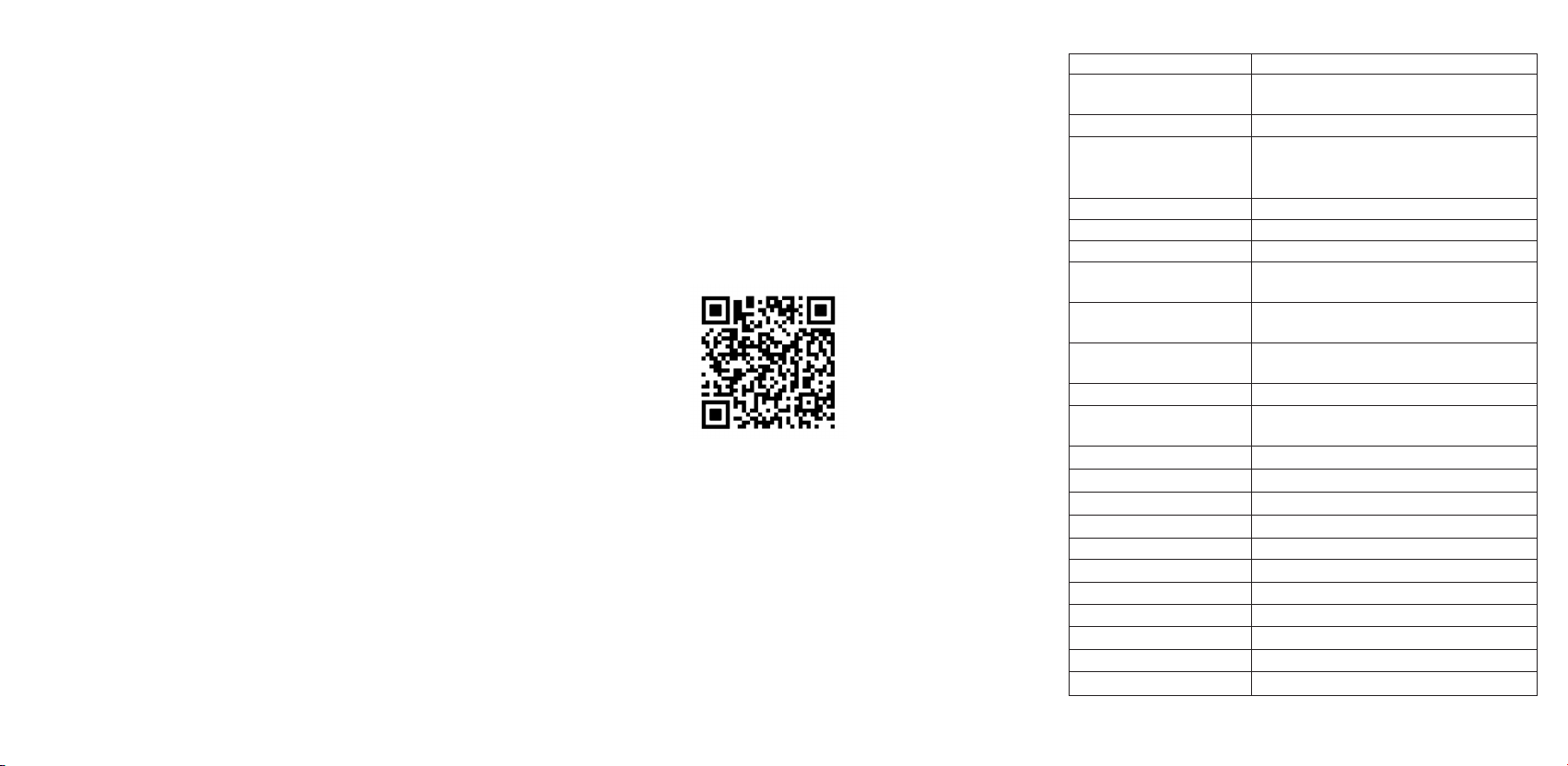
Scan the QR code below using your mobile browser or the built-in scan
function (Apple users can type "xthick" directly in the iOS Store search bar)
to access the search interface. Enter "xthick.apk" in the search bar to
download the App to your phone. After installation, open the App and
connect to the device via Bluetooth. The real-time data interface in the App
allows you to view live measurement data and statistical data.
Note: Before pairing or connecting via Bluetooth, enable Bluetooth on
both the device and your phone, and enable phone location services.
❹ ❺ ❻
8.3 Alarm Set
(1) Alarm switch: Press the confirmation key to activate or deactivate the
alarm. When the alarm switch is in the "OFF" position, the "Setthealarm
value" function cannot be activated.
(2) Set the alarm value: When the alarm switch is set to "ON", enter the
"Set the alarm value" menu to configure thickness ranges in different
colors (short-press the menu key to select the parameter, then use the
up/down keys to adjust the value; after completion, press the return key).
Depending on the measurement result, the backlight will illuminate in
green, yellow, or red. The conditions for each color illumination are as
follows:
①Green, accompanied by a "beep" sound. Conditions: The substrate is
iron, non-iron, or iron-zinc, and the thickness value falls within the green
range set in the menu.
②Yellow, accompanied by the audible prompt "beep-beep". Conditions:
The substrate is iron, non-iron, or iron-zinc, and the thickness value falls
within the yellow range set in the menu.
③Red, accompanied by the audible signal "beep-beep-beep". Conditions:
The thickness value falls within the red range set in the menu, or no metal
is detected. For special cases, when the base material is iron powder putty,
it displays bright red with a special audible alert.
8.4 BKL Set
Shortly press the menu key to enter the screen brightness settings
interface. The instrument supports four brightness levels: a short press of
the up key increases the screen brightness incrementally, while a short
press of the down key decreases it incrementally.
8.5 Unit
Short press the menu key to switch units.
8.6 Resolution
Short press the menu key to switch display resolution.
Note: When the selected unit changes, the resolution will automatically
adjust to the corresponding unit.
8.7 Bluetooth
Short press the menu key to turn Bluetooth on/off. After connecting to the
mobile app, the measurement interface will display in a fixed minimalist
large-screen style and cannot be switched.
Note: To reduce power consumption and extend battery life, you can turn
off Bluetooth when not in use.
8.8 Reset
Short press the menu key to restore factory settings. Use the up/down keys
Type
EC-680
Measuring principle
Iron: magnetic induction; Non-iron: eddy
current effect
Measuring range
0~5000μm
Accuracy
±(2%reading+1μm), ≤2000μm
±(3%reading+2μm), 2001~3000μm
±(5%reading+2μm), >3000μm
Resolution ratio
0.1μm, 1μm, 10μm, can be set in the menu
Calibration
Zero calibration
Unit
μm, mm, mil
Iron powder putty
identification range
0~2000μm
Identification range of
galvanized iron
3~1000μm
Minimum radius of
curvature of substrate
5mm convex surface; 25mm concave
surface
Minimum measuring area
Diameter 15mm
Minimum substrate
thickness
Iron: 0.20mm; Non-iron: 0.03mm
Reaction time
<0.5 seconds
Display
Color screen
USB data transmission
Supports (Type-C port)
Bluetooth and mobile App
Support
Service temperature
-10~50℃
Storage temperature
-20~60℃
Source
2 pcs AAA 1.5V alkaline batteries
Levels of protection
IP40
Outline dimension
108*67*28mm
Shell material
ABS
Weight
Approximately 64g (excluding the battery)
11. Functions and Technical Parameters

FCC Warnning:
This equipment has been tested and found to comply with the limits for a Class B digital device,
pursuant to part 15 of the FCC Rules. These limits are designed to provide
reasonable
protection against harmful interference in a residential installation. This equipment generates,
uses and can radiate radio
frequency
energy
and,
if
not
installed
and
used
in
accordance
with
the
instructions,
may cause
harmful
interference
to
radio
communications.
However,
there
is
no
guarantee
that interference
will
not
occur
in
a
particular
installation.
If
this
equipment
does
cause
harmful interference to radio or television reception, which can be
determined by turning the equipment off
and
on,
the
user
is
encouraged
to
try
to
correct
the interference
by
one
or
more
of
the following measures:
•
Reorient or relocate the receiving antenna.
•
Increase the separation between the equipment and receiver.
•
Connect the equipment into an outlet on a circuit different from that to which the receiver is
connected.
• Consult the dealer or an experienced radio/TV technician for help.
Caution:
Any
changes
or
modifications
to
this
device
not
explicitly
approved
by
manufacturer
could void your authority to operate this equipment.
This
device
complies
with
part
15
of
the
FCC
Rules.
Operation
is
subject
to
the
following
two
conditions:
(1)This
device
may
not
cause
harmful
interference,
and
(2)
this
device
must
accept
any
interference received, including interference that may cause undesired operation.
This
equipment
complies
with
FCC
radiation
exposure
limits
set
forth
for
an
uncontrolled
environment.
This
equipment
should
be
installed
and
operated
with
minimum
distance
0cm
between the radiator and your body.