
Zoom Lens
CN7x17
CN8x15
CN10x25
OPERATION MANUAL " Information display "
ENG
Read this operation manual before using the product.

Memo

ENGLISH

Memo

E3
Introduction
Introduction
Thank you for purchasing a Canon zoom lens.
This product comes with the following documents:
• Operation Manual "Before Using The Product"
(
Included with the product
)
• Operation Manual "Regulations"
(
Included with the product
)
• Operation Manual "Lens"
(
Web
)
• Operation Manual "Information display"
(
Web
)
• Quick guide "Information display"
(
Web
)
• Depth-of-eld
(
Web
)
Refer to this Operation Manual "Information display" for operating instructions and procedures for the information display.
The copyright for this manual is retained by Canon Inc.
Unauthorized copying or reproduction in whole or part is prohibited.

E4
Introduction
Contents
Introduction E3
Manual Layout .................................................................................................E7
Manual Conventions ...........................................................................................................E8
Part Names ......................................................................................................E9
Part Names and Functions .................................................................................................E9
Operation Key Names and Operation Methods .................................................................E9
Basic Sequence of Operations ....................................................................E10
1. Screen Organization E11
1.1 Top Screen ..............................................................................................E12
1.2 Menu Screen ...........................................................................................E14
2. Mode Selection E17
2.1 Modes ......................................................................................................E18
3. Operation in Basic Mode E19
3.1 Conguration from the Top Screen ......................................................E20
3.1.1 Selecting Basic Mode ..............................................................................................E21
3.1.2 Top Screen ..............................................................................................................E22
3.1.3 Specifying Auto Iris Gain .........................................................................................E24
3.1.4 Assigning Functions to the AUX Switch ................................................................... E25
3.1.5 Auto-Adjusting the Mechanical End .........................................................................E26
3.1.6 Assigning Functions to the AUX1 Switch ................................................................. E27
3.1.7 Zoom Tracking ON/OFF ..........................................................................................E28
3.1.8 Assigning Functions to the AUX2 Switch ................................................................. E29
3.1.9 Specifying Iris Torque ..............................................................................................E30
3.1.10 Specifying Zoom Curve Mode ...............................................................................E31

E5
Introduction
3.2 Conguration from the Menu Screen ...................................................E33
3.2.1 User Screen Settings ..............................................................................................E34
3.2.2 Switch Screen Settings ...........................................................................................E40
3.2.3 Preset Screen Settings ............................................................................................E44
3.2.4 Iris Screen Settings .................................................................................................E48
3.2.5 Zoom Screen Settings .............................................................................................E55
3.2.6 Focus Screen Settings ............................................................................................E59
3.2.7 Info Screen Settings ................................................................................................E61
3.2.8 Fol. Screen Settings ................................................................................................E68
3.3 List of Settings ........................................................................................E70
4. Operation in Full Mode E73
4.1 Conguration from the Top Screen ...................................................... E74
4.1.1 Selecting Full Mode .................................................................................................E75
4.1.2 Top Screen ..............................................................................................................E76
4.1.3 Switching Users .......................................................................................................E78
4.1.4 Switching to Basic Mode .........................................................................................E79
4.1.5 Auto-Adjusting the Mechanical End .........................................................................E80
4.1.6 Specifying Iris Gain .................................................................................................E81
4.1.7 Zoom Tracking ON/OFF ..........................................................................................E83
4.1.8 Assigning Functions to the AUX Switch ................................................................... E84
4.1.9 Specifying Iris Torque ..............................................................................................E85
4.1.10 Assigning Functions to the AUX1 Switch ............................................................... E86
4.1.11 Assigning Functions to the VTR Switch ................................................................. E87
4.1.12 Assigning Functions to the AUX2 Switch ............................................................... E88
4.1.13 Assigning Functions to the RET Switch ................................................................. E89
4.1.14 Specifying Zoom Curve Mode ...............................................................................E90
4.1.15 Assigning Functions to the Seesaw .......................................................................E92
4.1.16 Specifying Iris A/M Switch .....................................................................................E93
4.1.17 Escape Operation ..................................................................................................E94
4.2 Conguration from the Menu Screen ...................................................E95
4.2.1 User Screen Settings ..............................................................................................E96
4.2.2 Switch Screen Settings ......................................................................................... E113
4.2.3 Preset Screen Settings ..........................................................................................E121
4.2.4 Iris Screen Settings ...............................................................................................E127
4.2.5 Zoom Screen Settings ...........................................................................................E134

E6
Introduction
4.2.6 Focus Screen Settings ..........................................................................................E145
4.2.7 Info Screen Settings ..............................................................................................E147
4.2.8 Fol. Screen Settings ..............................................................................................E154
4.3 List of Settings ......................................................................................E156
5. Operation in Analog Mode E159
5.1 Conguration from the Top Screen .................................................... E160
5.1.1 Selecting Analog Mode ..........................................................................................E161
5.1.2 Top Screen ............................................................................................................E162
5.1.3 Specifying Auto Iris Gain .......................................................................................E163
5.1.4 Switching to Basic Mode .......................................................................................E164
5.2 Conguration from the Menu Screen .................................................E165
5.2.1 User Screen Settings ............................................................................................E166
5.3 List of Settings ......................................................................................E171
E7
Introduction
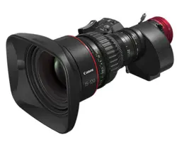
Manual Layout
Pages with instructions are organized as follows.
E94
4. Operation in Full Mode
Zoom
Iris
[ Z.M. ]
[ I-Gain ]
[Adj]
[]
MENU
1
A
Fr1P
[ Basic ]
[Trk]
OFF
[I-Tq]H
[]
MENU
MENU
1
RET
R
Fr1P
A 2
Norm
AM
Zoom
[ Z.M. ]
[]
MENU
MENU
1
RET
R
Fr1P
A 2
Norm
AM
Iris
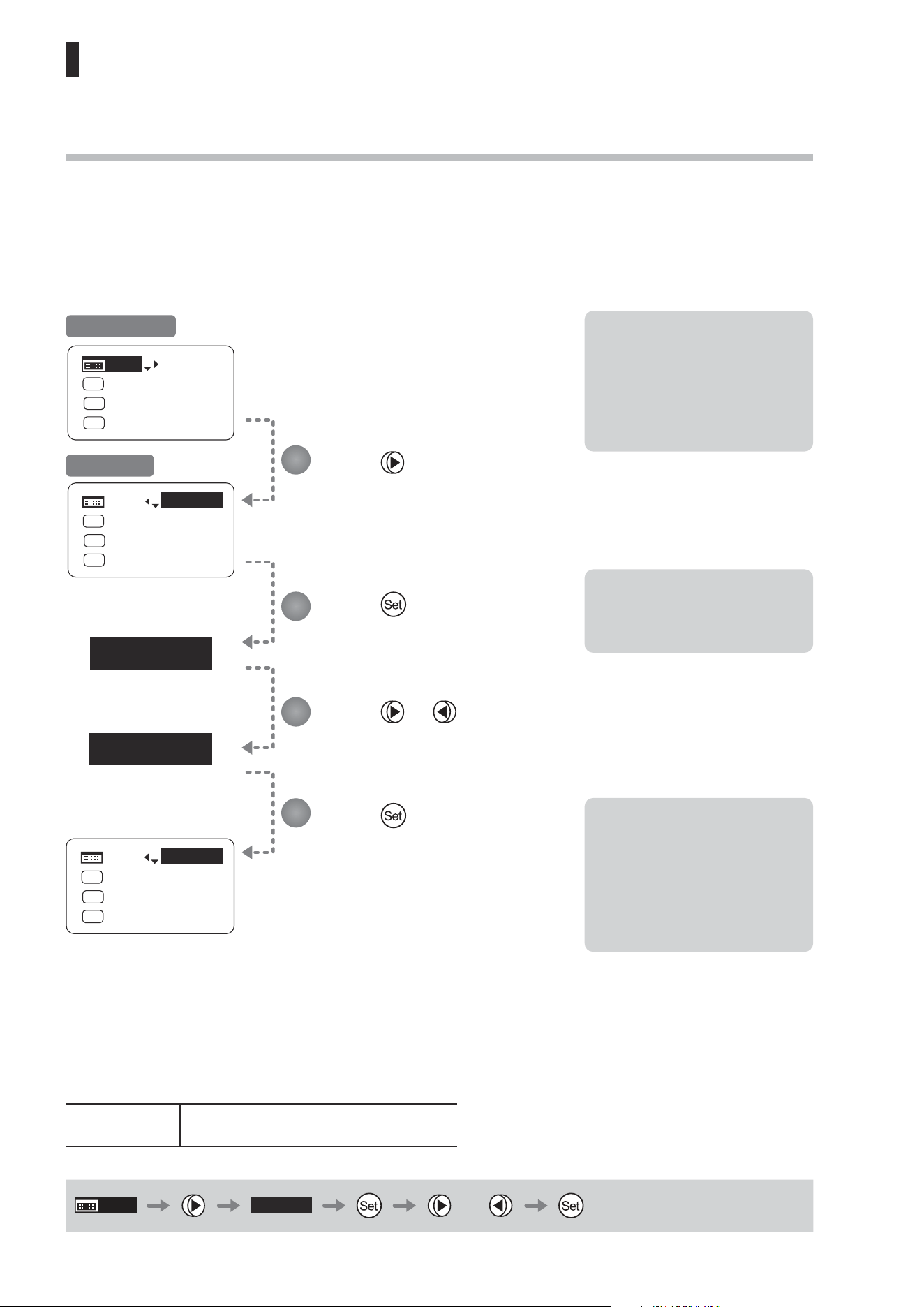
4.1.15 Assigning Functions to the Seesaw
The zoom seesaw switch can be programmed to control either the {Zoom} or {Iris}.
Important
First, switch to the user for whom the settings apply.
(For instructions, see “4.1.3 Switching Users” or “4.2.1 User Screen Settings: Switching Users.”)
Press six times and once.
The previous or default function is highlighted.
Press .
The display starts blinking.
Press or .
Press left or right to switch the function to
{Zoom} or {Iris}.
Press .
The display changes from blinking to
highlighted, indicating con rmation.
Options
(D)
Zoom Iris
Description Zoom operation Iris operation
(D): Default value
MENU
× 6
Zoom
or
1
2
3
4
Initial Top Screen
Note: Note on Iris Assignment
1. The seesaw switch will no
longer control zooming.
2. To control the iris with the
rocker switch, you must set
the iris mode to manual.
3. Press the Telephoto side to
open the iris, or press the
Wide end side to close it.
4. Zoom speed control
adjustments also apply to iris
control, and you can specify
the maximum iris speed. (See
“4.2.5 Zoom Screen Settings:
Specifying Maximum Zoom
Speed Control.)
Chapter title
Function title
Summary of function,
points to note
Operating procedure
Notes
Quick reference for
operating procedure
Page number
List of available
functions or options

E8
Introduction
Manual Conventions
The following conventions are used in this manual.
Convention Description Example
∗∗
screen Names of screens are underlined.
The Top screen is displayed.
[ ] Names of setting items are enclosed in square brackets. [Frame 1] is underlined.
{ } Names of options are enclosed in curly brackets. Select {FAST}.
E9
Introduction
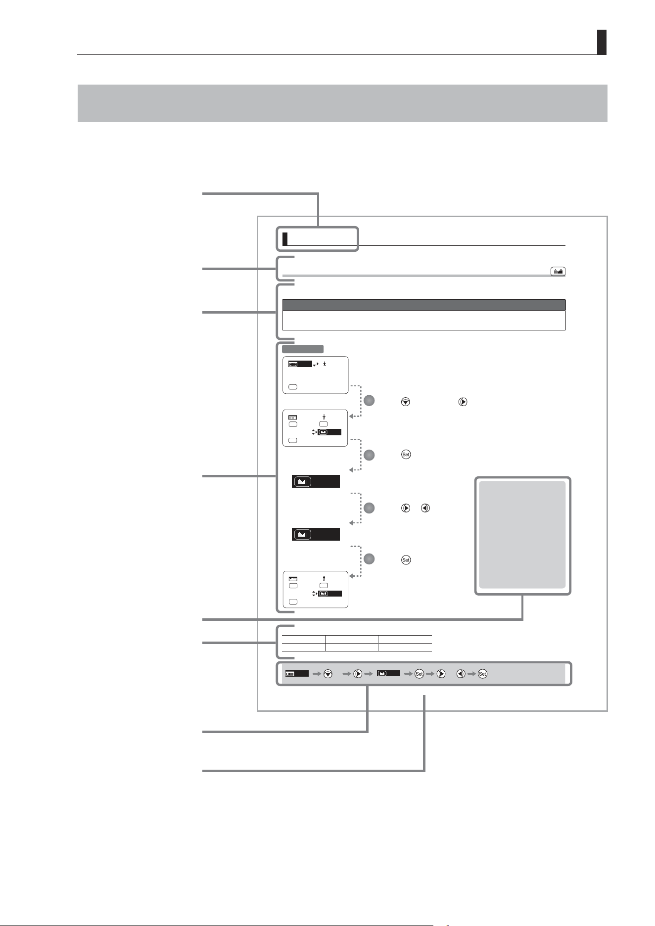
Part Names
Part Names and Functions
Display
Activated when the Display switch is
pressed.
Turns o automatically if left idle for
two minutes.
DISPLAY
Display switch
Press to activate the display.
One press turns on the display, and
another turns it o.
Control keys
Used to congure all settings shown
on the display.
Identied with ve key names,
depending on how this interface is
used.
(See the following table, “Using the
Control Keys.”)
Operation Key Names and Operation Methods
Key Operation Details Manual Convention
Set key
Press
Pressed when { } is displayed, or when entering a
selection.
Right key
Move right
Can be used when { } is displayed.
Left key
Move left
Can be used when { } is displayed.
Up key
Move up
Can be used when { } is displayed.
Down key
Move down
Can be used when { } is displayed.
E10
Introduction
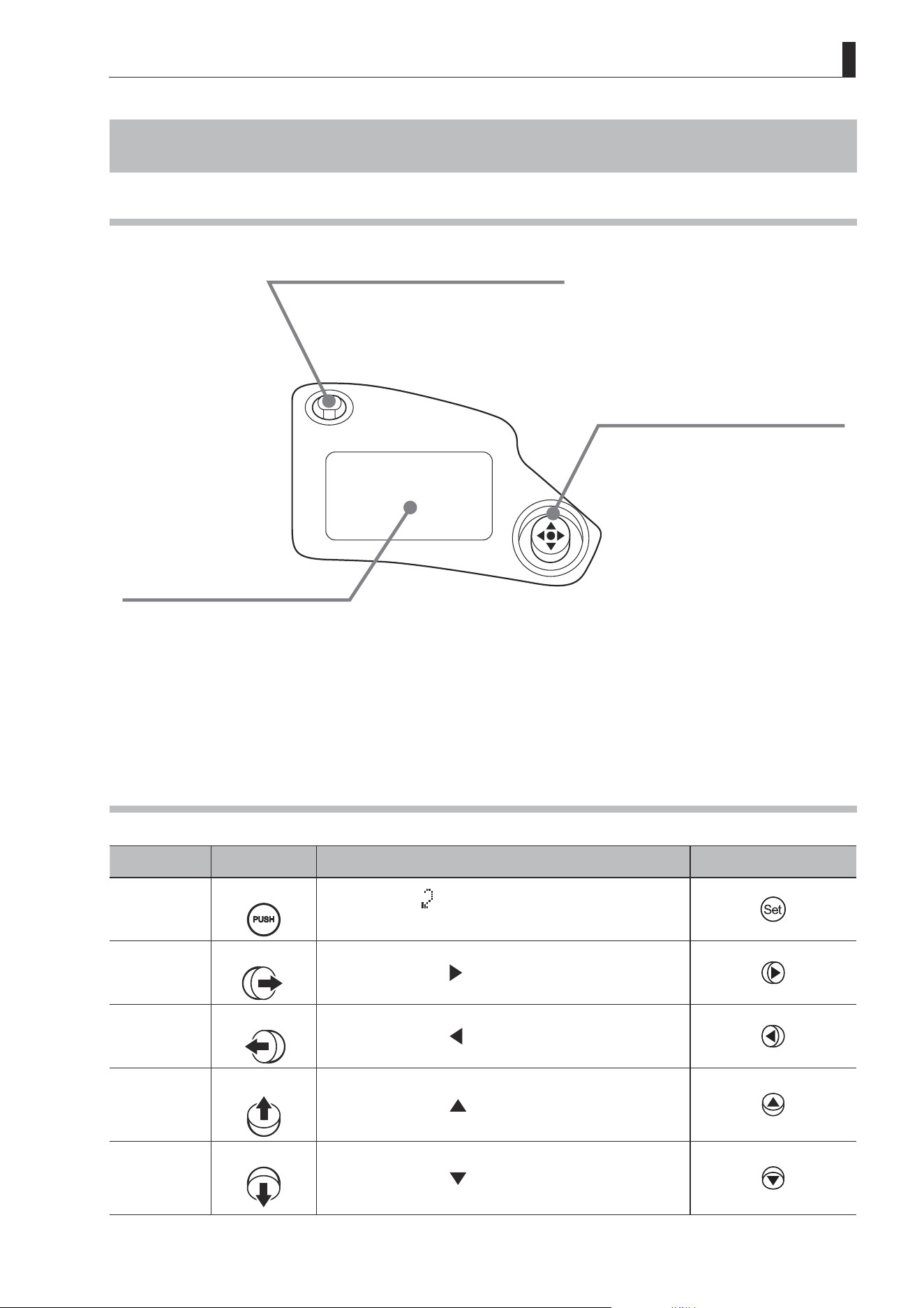
Basic Sequence of Operations
DISPLAY
[Trk]
OFF
Shtl
A 1
A 2
MENU
IG: 50
A
Fr1P
Fr1P
[I-Tq]H
[Adj]
DISPLAY
Press the Display switch.
Press the Display switch.
The display is now illuminated.
The display is turned o.
Changes are saved.
Use the control keys to complete settings.
1
2
3
4
Turn on the lens.
DISPLAY
MENU
[Trk]
ON
Shtl
A 1
A 2
IG: 50
A
Fr1P
Fr1P
[I-Tq]H
[Adj]
Important
For Reference: Display appearance when restoring original settings
Restoring the Original
Settings
The original settings can be restored, in
the case of incorrect settings or if you have
tried some settings tentatively.
For details, see “Resetting Values”
in “3. Operation in Basic Mode” or
“4. Operation in Full Mode.”
Basic Mode
ResetAll
User
User:
B
y/n
Full Mode
ResetAll
User
User:
AllUser:
1
y/n
y/n
Note: For instructions on turning the lens on, refer
to the camera manual.
Note: The display turns off automatically after two
minutes if no control keys are pressed. (Auto
O.) However, the display remains active as
long as the Fol. screen is shown. In this case,
it is only deactivated when you press the Dis-
play switch.
Note: Any changes to settings are saved even if the
display is automatically deactivated, just as
they are when it is switched o manually.
When the display is deactivated manually,
changes to settings are saved and the display
is turned o.
However, if the lens is turned off while the
display is on, changes to settings may not be
saved.

Screen Organization
1
INFORMATION DISPLAY
E12
1. Screen Organization
1. Screen Organization
Screens contain 22 setting items in Basic mode, 38 in Full mode, and 3 in Analog mode, with Basic and Full modes also
including a “follow” screen containing three setting items that have relative values. To access frequently used items on
the Top screen, press the Display switch. All settings can be congured from the Menu screen, which also includes
advanced settings. (See “Menu Screen” in “1. Screen Organization.”)
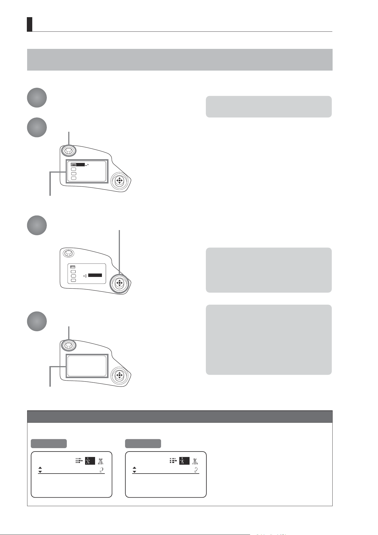
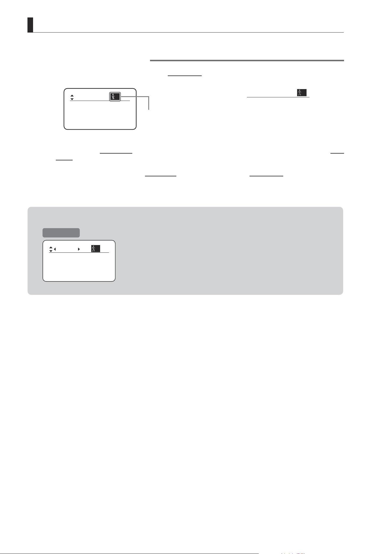
1.1 Top Screen
(For instructions on conguring the settings, see “Conguration from the Top Screen” in each mode.)
The Top screen contains 9 setting items in Basic mode, 15 in Full mode, and 3 in Analog mode.
Initial Top Screen in Basic Mode
[Trk]
OFF
Shtl
A 1
A 2
MENU
IG: 50
A
Fr1P
Fr1P
[I-Tq]H
[Adj]
Items not scrolled
Items displayed by scrolling
MENU
[ I-Tq ] H
A 1
IG: 50
[Trk]
OFF
[ Z.M. ]
A 2
Fr1P
Shtl
Top Screen in Basic Mode
Of the 9 setting items in Basic mode, the 8 more common are
shown on the Top screen. The other 1 can be accessed by
pressing down to scroll down the screen.
1. Go to Menu screen
2. Auto iris gain settings
3. AUX switch assignment
4. Mechanical end auto-adjustment
5. AUX1 switch assignment
6. Zoom tracking ON/OFF
7. AUX2 switch assignment
8. Iris torque settings
9. Zoom curve mode settings
E13
1. Screen Organization
Initial Top Screen in Full Mode
[ I-Gain ]
[Adj]
[]
MENU
1
A
Fr1P
[ Basic ]
[Trk]
OFF
[I-Tq]H
Items not scrolled
Items displayed by scrolling
[]
MENU
1
Norm
AM
Zoom
RET
R
A 2
Fr1P
[ Z.M. ]
Top Screen in Full Mode
Of the 15 setting items in Full mode, the 8 most common are
shown on the Top screen. The other 6 can be accessed by
pressing down to scroll down the screen.
1. Go to Menu screen
2. Switch users
3. Switch to Basic mode
4. Mechanical end auto-adjustment
5. Iris gain settings
6. Zoom tracking ON/OFF
7. AUX switch assignment
8. Iris torque settings
9. AUX1 switch assignment
10. VTR switch assignment
11. AUX2 switch assignment
12. RET switch assignment
13. Zoom curve mode settings
14. Seesaw switch assignment
15. Iris A/M switch setting
Initial Top Screen in Analog Mode
MENU
IG: 50
[ Basic ]
Top Screen in Analog Mode
1. Go to Menu screen
2. Auto iris gain settings
3. Switch to Basic mode
E14
1. Screen Organization
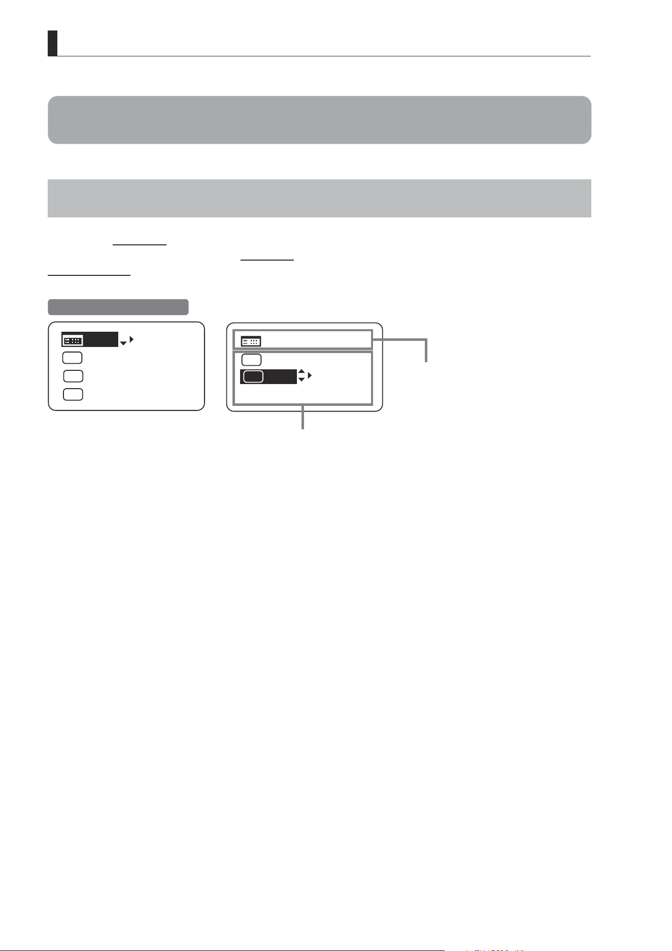
1.2 Menu Screen
(For instructions on conguring the settings, see the “Menu Screen” section in the descriptions of each mode.)
Setting items in each mode and on the “follow” screen are organized by function. All of these screens are collectively
referred to as the Menu screen.
*1
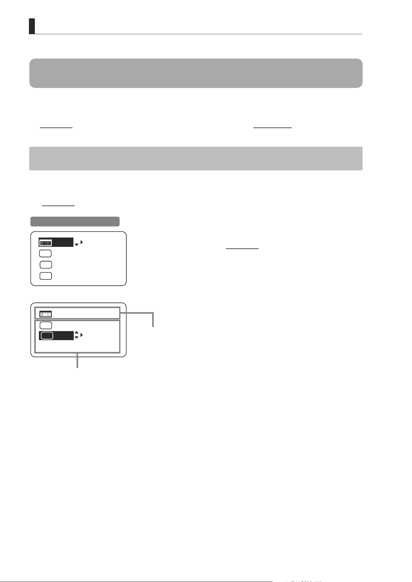
Menu Screen in Basic Mode
In Basic mode, the 22 setting items and three “follow” settings with relative values are organized by function into the
following 8 screens.
Mode:
User
Basic
Access:
ResetAll
B
Unlock
Icon of selected screen
is highlighted.
Other icons, for
unselected screens, are
not highlighted.
1. User screen
B
2. Switch screen
3. Preset screen
4. Iris screen
5. Zoom screen
[ ]
6. Focus screen
7. Info screen
8. Fol. screen
*1
: There is no single Menu screen. Instead, these 8 screens are collectively referred to as the Menu screen.
To access these screens, select [MENU] on the Top screen and press the Set key. Initially, the User screen is displayed.
To access other screens, press left or right.
Mode:
User
Basic
Access:
ResetAll
B
Unlock
Switch
B
AUX2:
A
A 1
AUX1:
A 2
Fr1P
AUX:
Fr1P
Shtl
Frame1:
Preset
Zoom
Frame2: Zoom
ZSpeed: 800
CurveMode
VR-Dem: ON
Zoom
[]
CurveMode
Focus
[]
Fol.
Iris:
Zoom:
Focus:
0000
1000
0000
B
Info
Encoder:
OFF
S/N
3D:
OFF
Menu Screen in Basic Mode
User screen
Zoom screen
Switch screen
Focus screen
Preset screen
Info screen
Iris screen
Fol. screen
Iris
[]
[ I-Gain ]
Torque: High
Comp:ON
E15
1. Screen Organization
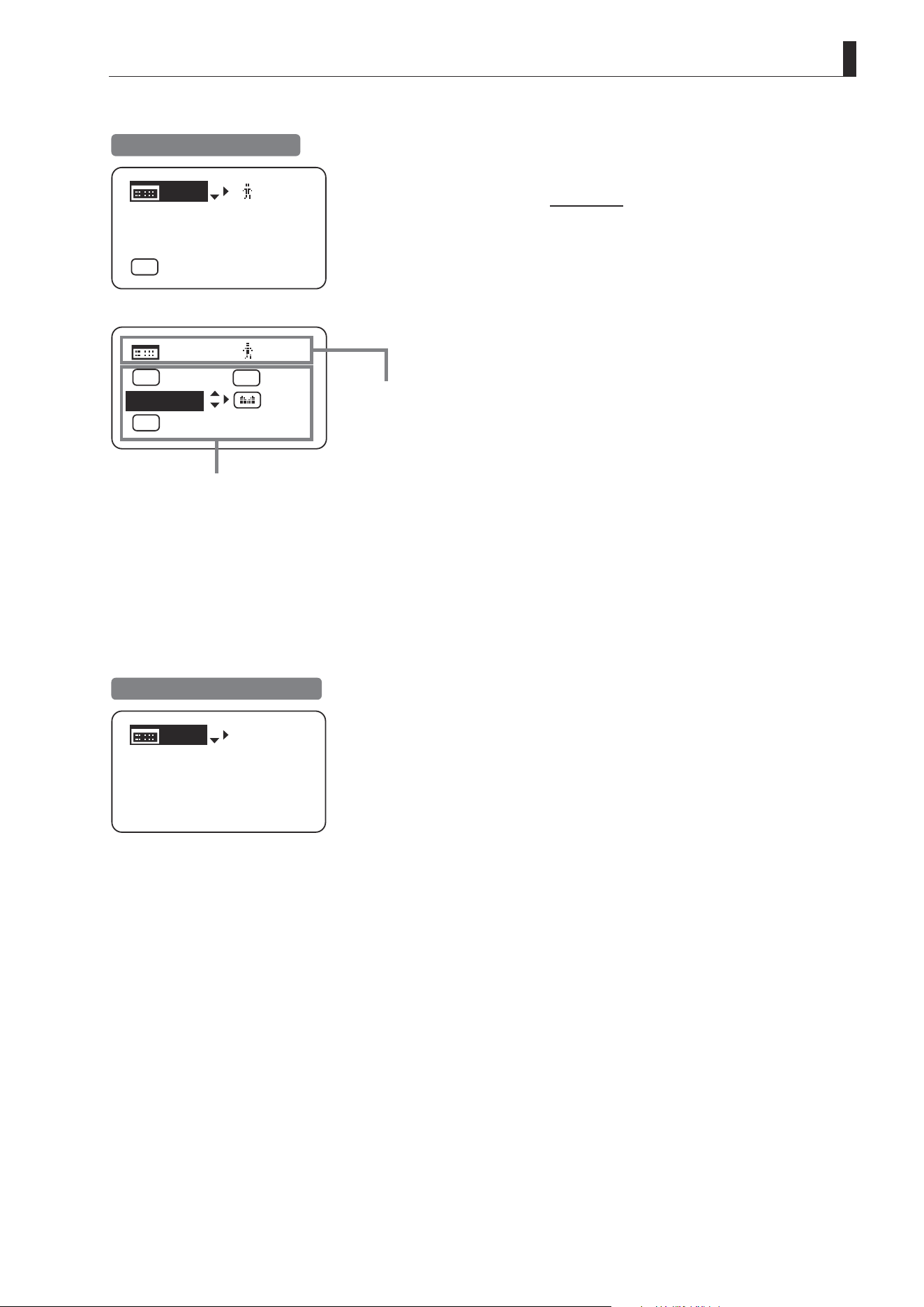
Menu Screen in Full Mode
In Full mode, the 38 setting items and three “follow” settings with relative values are organized by function into the
following 8 screens.
No. :
User
1
Name:
Mode:
Full
1
Icon of selected screen
is highlighted.
Other icons, for
unselected screens, are
not highlighted.
1. User screen
1
2. Switch screen
3. Preset screen
4. Iris screen
5. Zoom screen
[ ]
6. Focus screen
7. Info screen
8. Fol. screen
*1
: There is no single Menu screen. Instead, these 8 screens are collectively referred to as the Menu screen.
To access these screens, select [MENU] on the Top screen and press the Set key. Initially, the User screen is displayed.
To access other screens, press left or right.
Menu Screen in Full Mode
User screen
Zoom screen
Switch screen
Focus screen
Preset screen
Info screen
Iris screen
Fol. screen
No. :
User
1
Name:
Mode:
Full
1
Switch
1
AUX2:
A
A 1
AUX1:
A 2
Fr1P
AUX:
Fr1P
Shtl
Frame1:
Preset
Zoom
Frame2: Zoom
ZSpeed: 800
Iris
[]
[ I-Gain ]
Torque: High
Comp:ON
Tracking:
CurveMode
OFF
Movement
Zoom
[]
CurveMode
Focus
[]
Fol.
Iris:
Zoom:
Focus:
0000
1000
0000
1
Info
Encoder:
OFF
S/N
3D:
OFF
E16
1. Screen Organization
Menu Screen in Analog Mode
Menu Screen in Analog Mode
In Analog mode, 2 setting items are presented as the User screen.
Icon of selected screen is
highlighted.
Mode:
User
Analog
Access:
A
Unlock
1. User screen
A
*1
: There is no single Menu screen. Instead, screens accessed by selecting [MENU] are collectively referred to as the Menu
screen.
To access this screen, select [MENU] on the Top screen and press the Set key. The User screen is now displayed.
User screen
Mode:
User
Analog
Access:
A
Unlock

Mode Selection
2
INFORMATION DISPLAY

E18
2. Mode Selection
2. Mode Selection
2.1 Modes
The following 3 modes are available. Choose a mode that suits your purpose or preference.
1. Basic Mode: Restricted settings and information. Recommended for users who do not require sophisticated
settings. This is the default mode.
2. Full Mode: All settings and information are available.
3. Analog Mode: Used when no digital functions are needed.
For details, see “3. Operation in Basic Mode,” “4. Operation in Full Mode,” or “5. Operation in Analog Mode.”

Operation in Basic Mode
3
INFORMATION DISPLAY
E20
3. Operation in Basic Mode
3. Operation in Basic Mode
3.1 Conguration from the Top Screen
To access the Top screen, press the Display switch.
A total of 9 items can be congured on the Top screen in Basic mode. The rst screen displayed is referred to as the
Initial Top screen. Status of some items can be checked simply by accessing this screen.
Initial Top Screen in Basic Mode
[Trk]
OFF
Shtl
A 1
A 2
MENU
IG: 50
A
Fr1P
Fr1P
[I-Tq]H
[Adj]
Items not scrolled
Items displayed by scrolling
MENU
[ I-Tq ] H
A 1
IG: 50
[Trk]
OFF
[ Z.M. ]
A 2
Fr1P
Shtl
E21
3. Operation in Basic Mode
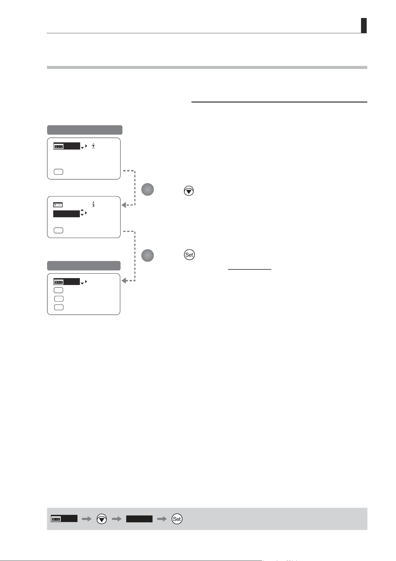
3.1.1 Selecting Basic Mode
Basic mode is the default mode, but it can also be accessed from other modes as follows.
Switching from Full to Basic Mode
MENU
MENU
[ Basic ]
[ I-Gain ]
[Adj]
[]
MENU
1
A
Fr1P
[ Basic ]
[Trk]
OFF
[I-Tq]H
[ I-Gain ]
[Adj]
[]
1
A
Fr1P
[Trk]
OFF
[I-Tq]H
[Trk]
OFF
Shtl
A 1
A 2
MENU
IG: 50
A
Fr1P
Fr1P
[I-Tq]H
[Adj]
Initial Top Screen in Full Mode
Initial Top Screen in Basic Mode
MENU
[ Basic ]
Press .
[Basic] is highlighted.
Press .
The mode switches, and the Initial Top screen in Basic mode is displayed.
1
2
E22
3. Operation in Basic Mode
3.1.2 Top Screen
A total of 9 items can be congured on the Top screen in Basic mode, and 8 items are shown on the Initial Top screen.
The other items can be accessed by pressing down to scroll down the screen. (See the following gure.)
Status of some items can be checked simply by accessing this screen. (Shown in the gure below.
*1
)
*1
Inside
: Items that show the current setting
status.
Example:
Shtl
A 1
indicates that the AUX1
switch is assigned to the Shuttle
function.
3
: White numbers against a black background
indicate the number of the switch on a
drive unit to which the function is assigned.
[Trk]
OFF
Shtl
A 1
A 2
[ I-Tq ] H
[ Adj ]
IG: 50
A
Fr1P
Fr1P
MENU
[ Z.M. ]
9
1
4
8
2
7
6
3
3
5
Items Displayed by Scrolling
Initial Top Screen
E23
3. Operation in Basic Mode
1
MENU
Menu screen
See “3.2 Conguration from the Menu Screen.”
5
6
[Trk]
Zoom tracking
Switch to ON when using zoom tracking.
See “3.1.7 Zoom Tracking ON/OFF.”
1 2
IG
Auto iris gain
Adjust the auto iris gain value as needed.
See “3.1.3 Specifying Auto Iris Gain.”
7
A 2
AUX2 switch
By default, the AUX2 switch for a zoom demand
is assigned to the {Frame Preset 1} function,
but it can be reassigned as needed.
See “3.1.8 Assigning Functions to the AUX2
Switch.”
3
A
AUX switch
By default, the AUX switch for a drive unit is
assigned to the {Frame Preset 1} function, but it
can be reassigned as needed.
See “3.1.4 Assigning Functions to the AUX
Switch.”
7
8
[I-Tq]
Iris torque
Adjust the level of torque in manual control of
the iris ring as needed.
See “3.1.9 Specifying Iris Torque.”
43
[Adj]
Mechanical end auto-adjustment
Perform automatic adjustment of the mechanical
end in zoom, focus, and iris operations on the
lens and drive unit.
See “3.1.5 Auto-Adjusting the Mechanical End.”
9
[Z.M.]
Zoom curve mode
Adjust zoom speed in response to pressing
the zoom seesaw switch or tilting the analog
demand thumb ring.
See “3.1.10 Specifying Zoom Curve Mode.”
5
A 1
AUX1 switch
By default, the AUX1 switch for a zoom demand
is assigned to the {Shuttle} function, but it can
be reassigned as needed.
See “3.1.6 Assigning Functions to the AUX1
Switch.”
E24
3. Operation in Basic Mode
3.1.3 Specifying Auto Iris Gain [IG]
Although this value is factory-set, it can be adjusted as needed.
To adjust the value, use either the auto iris gain adjustment trimmer (refer to the operation manual "Lens") or display
operations. Regardless of the method of adjustment used, the most recent setting takes precedence.
The same auto iris gain value applies to all users.
Options 01 to 99
Description Minimum gain Maximum gain
Default: Varies depending on the factory-set value, but corresponds to the value determined with the iris gain adjustment trimmer.
MENU
IG
or
MENU
IG: 50
IG: 50
IG: 50
IG: 50
IG: 51
IG: 51
[Trk]
OFF
Shtl
A 1
A 2
MENU
IG: 50
A
Fr1P
Fr1P
[I-Tq]H
[Adj]
[Trk]
OFF
Shtl
A 1
A 2
A
Fr1P
Fr1P
[I-Tq]H
[Adj]
MENU
IG: 51
IG: 51
[Trk]
OFF
Shtl
A 1
A 2
A
Fr1P
Fr1P
[I-Tq]H
[Adj]
Note: Do the following when
adjusting gain while checking
iris operation.
→ Conrm that the drive unit A/M
switch is set to [Auto] mode.
→ Set the camera iris mode to
[Auto].
Note: As you look at the lens iris
ring, set it to the position of
maximum gain at which “focus
hunting” does not occur.
Note: The current iris gain value
is retained even if you reset
other settings as described in
“3.2.1 Resetting Values.” For
this reason, you will no longer
be able to view the default
setting. If necessary, make
a note of the default setting
before adjusting this value.
1
2
3
4
Press .
Your selection is now highlighted.
Press .
The display starts blinking.
Press or .
Press left or right until you reach
the desired value.
Press .
The display changes from blinking to
highlighted, indicating conrmation.
Initial Top Screen
Screen A
E25
3. Operation in Basic Mode
Fr1P
A
RET
A
MENU
A
Fr1P
A
RET
[Trk]
OFF
Shtl
A 1
A 2
MENU
IG: 50
A
Fr1P
Fr1P
[I-Tq]H
[Adj]
[Trk]
OFF
Shtl
A 1
A 2
IG: 50
Fr1P
[I-Tq]H
[Adj]
MENU
[Trk]
OFF
Shtl
A 1
A 2
IG: 50
Fr1P
[I-Tq]H
[Adj]
3.1.4 Assigning Functions to the AUX Switch
Assign your desired functions to the AUX switch.
Options
(D)
Fr1P Fr1F Fr2P Fr2F Sped Shtl NON VTR RET
Description
Framing Preset1
switch
(preset speed)
Framing Preset1
switch
(max. speed)
Framing Preset2
switch
(preset speed)
Framing Preset2
switch
(max. speed)
Speed Preset
switch
Shuttle-Shot
switch
No function VTR switch RET switch
(D): Default value
MENU
Shtl
A
or
Press .
The default function is highlighted.
Press .
The display starts blinking.
Press or .
Press left or right until you reach the desired function.
Press .
The display changes from blinking to highlighted, indicating conrmation.
1
2
3
4
Initial Top Screen
E26
3. Operation in Basic Mode
MENU
[Adj]
[Trk]
OFF
Shtl
A 1
A 2
MENU
IG: 50
A
Fr1P
Fr1P
[I-Tq]H
[Adj]
[Trk]
OFF
Shtl
A 1
A 2
IG: 50
A
Fr1P
Fr1P
[I-Tq]H
Lens
AutoAdjust
OK?
y/n
Auto-Adjustment:
Succeeded
Lens Interface:
Connected
MENU
[Adj]
3.1.5 Auto-Adjusting the Mechanical End [Adj]
Perform automatic adjustment of the mechanical end in zoom, focus, and iris operations on the lens and drive unit.
Note
If “Auto-Adjustment: Error/Lens Interface: Non-Connected” is displayed after adjustment, contact Canon or your
dealer.
Press and then .
Your selection is now highlighted.
Press .
The display switches to the Auto-Adjustment screen.
Press and then .
Adjustment now begins.
During adjustment, the screen blinks.
After this, adjustment is nished.
Press
after adjustment to return to Screen A.
1
2
3
Initial Top Screen
Note: In manual zoom or focus
modes, “Please Check Servo/
Manual OK?” is displayed after
step 3. After checking, press
to start adjustment.
Screen A
E27
3. Operation in Basic Mode
3.1.6 Assigning Functions to the AUX1 Switch
Assign your desired functions to the AUX1 switch.
Options Fr1P Fr1F Fr2P Fr2F Sped
(D)
Shtl NON VTR RET
Description
Framing Preset1
switch
(preset speed)
Framing Preset1
switch
(max. speed)
Framing Preset2
switch
(preset speed)
Framing Preset2
switch
(max. speed)
Speed Preset
switch
Shuttle-Shot
switch
No function VTR switch RET switch
(D): Default value
MENU
× 2
Shtl
A
or
Press twice.
The default function is highlighted.
Press .
The display starts blinking.
Press or .
Press left or right until you reach the desired function.
Press .
The display changes from blinking to highlighted, indicating conrmation.
Shtl
A1
NON
A1
Shtl
MENU
A 1
[Trk]
OFF
Shtl
A 1
A 2
MENU
IG: 50
A
Fr1P
Fr1P
[I-Tq]H
[Adj]
[Trk]
OFF
A 2
IG: 50
A
Fr1P
Fr1P
[I-Tq]H
[Adj]
NON
MENU
A 1
[Trk]
OFF
A 2
IG: 50
A
Fr1P
Fr1P
[I-Tq]H
[Adj]
1
2
3
4
Initial Top Screen
E28
3. Operation in Basic Mode
Options
(D)
OFF ON
(D): Default value
MENU
× 2
[Trk]
OFF
or
3.1.7 Zoom Tracking ON/OFF [Trk]
Activate or deactivate zoom tracking as needed.
Important
In Basic mode, any adjustments to this setting are not retained when the lens is turned o, and the default value is
restored on startup.
[Trk]
OFF
[Trk]
ON
Shtl
A 1
A 2
IG: 50
A
Fr1P
Fr1P
[I-Tq]H [Z.M.]
MENU
[Trk]
ON
[Trk]
OFF
[Trk]
OFF
Shtl
A 1
A 2
MENU
IG: 50
A
Fr1P
Fr1P
[I-Tq]H
[Adj]
Shtl
A 1
A 2
IG: 50
A
Fr1P
Fr1P
[I-Tq]H
[Adj]
MENU
Press twice and once.
The default setting is highlighted.
Press .
The display starts blinking.
Press or .
Press left or right to switch the function {ON} or {OFF}.
Press .
The display changes from blinking to highlighted, indicating conrmation.
1
2
3
4
Initial Top Screen
E29
3. Operation in Basic Mode
3.1.8 Assigning Functions to the AUX2 Switch
Assign your desired functions to the AUX2 switch.
Press three times.
The default function is highlighted.
Press .
The display starts blinking.
Press or .
Press left or right until you reach the desired function.
Press .
The display changes from blinking to highlighted, indicating conrmation.
Fr1P
A2
RET
A2
A 2
MENU
Fr1P
[Trk]
OFF
Shtl
A 1
A 2
MENU
IG: 50
A
Fr1P
Fr1P
[I-Tq]H
[Adj]
[Trk]
OFF
Shtl
A 1
IG: 50
[I-Tq]H
[Z.M.]
A 2
MENU
RET
[Trk]
OFF
Shtl
A 1
IG: 50
[I-Tq]H
[Z.M.]
Options
(D)
Fr1P Fr1F Fr2P Fr2F Sped Shtl NON VTR RET
Description
Framing Preset1
switch
(preset speed)
Framing Preset1
switch
(max. speed)
Framing Preset2
switch
(preset speed)
Framing Preset2
switch
(max. speed)
Speed Preset
switch
Shuttle-Shot
switch
No function VTR switch RET switch
(D): Default value
MENU
× 3
A 2
Fr1P
or
1
2
3
4
Initial Top Screen
E30
3. Operation in Basic Mode
3.1.9 Specifying Iris Torque [I-Tq]
Specify the desired level of torque in manual control of the iris ring.
Press three times and once.
The default function is highlighted.
Press .
The display starts blinking.
Press or .
Press left or right to switch the function to {H} or {L}.
Press .
The display changes from blinking to highlighted, indicating conrmation.
[ I-Tq ] H
[ I-Tq ] L
A 2
Fr1P
[I-Tq]H
[Trk]
OFF
Shtl
A 1
A 2
MENU
IG: 50
A
Fr1P
Fr1P
[I-Tq]H
[Adj]
MENU
[Trk]
OFF
Shtl
A 1
IG: 50
[Z.M.]
A 2
Fr1P
[I-Tq]L
MENU
[Trk]
OFF
Shtl
A 1
IG: 50
[Z.M.]
Options
(D)
H L
Description High torque Low torque
(D): Default value
MENU
× 3
[ I-Tq ] H
or
1
2
3
4
Initial Top Screen
E31
3. Operation in Basic Mode
CurveMode
Zoom
Demand:
Seesaw:
5
5
[]
CurveMode
Zoom
Demand:
Seesaw:
D5
5
CurveMode
Zoom
Demand:
Seesaw:
3
5
[]
[]
[I-Tq]H
[Z.M.]
[Trk]
OFF
Shtl
A 1
A 2
MENU
IG: 50
A
Fr1P
Fr1P
[I-Tq]H
[Adj]
A 2
Fr1P
MENU
[Trk]
OFF
Shtl
A 1
IG: 50
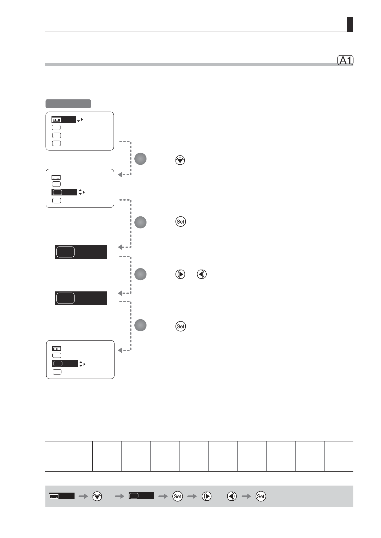
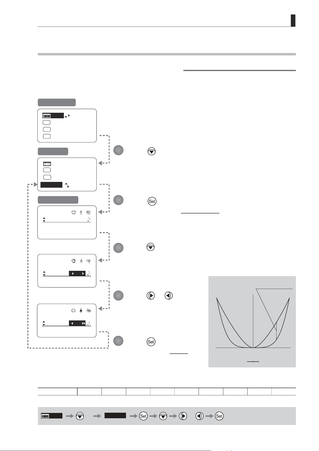
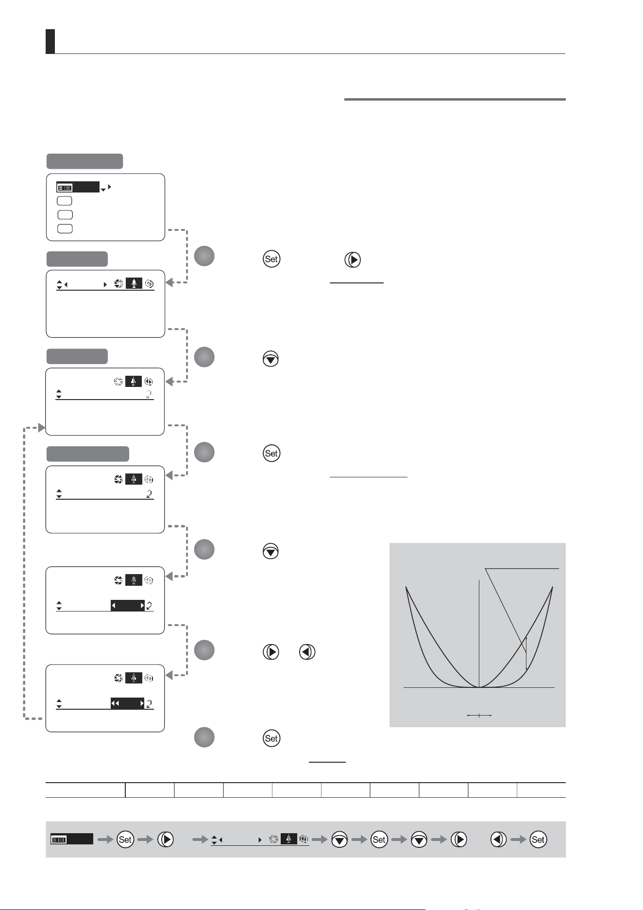
3.1.10 Specifying Zoom Curve Mode [Z.M.]
Specifying Seesaw Switch Responsiveness
Congure the responsiveness of zoom speed adjustment in response to pressing the zoom seesaw switch.
(Note: Another screen is displayed when this setting is congured.)
Press four times.
Your selection is now highlighted.
Press .
The display switches to the CurveMode screen.
Press .
[Seesaw] is underlined.
The default value is highlighted.
Press or .
Press left or right until you reach
the desired value.
Press .
The display reverts to Screen A.
(1)
(9)
Responsiveness to
zoom mode adjustment
Maximum
Zoom Speed
Wide Angle Telephoto
Extent of pressing the zoom seesaw switch
Zoom Direction
Options 1 2 3 4
(D)
5 6 7 8 9
(D): Default value
MENU
× 4
[Z.M.]
or
1
2
3
4
5
Initial Top Screen
Screen A
CurveMode Screen
E32
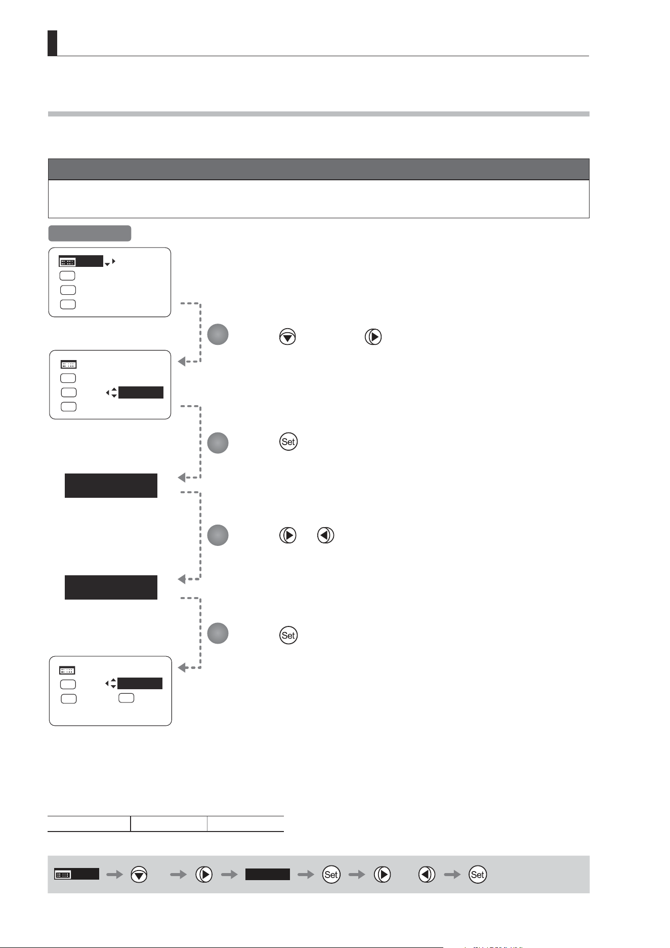
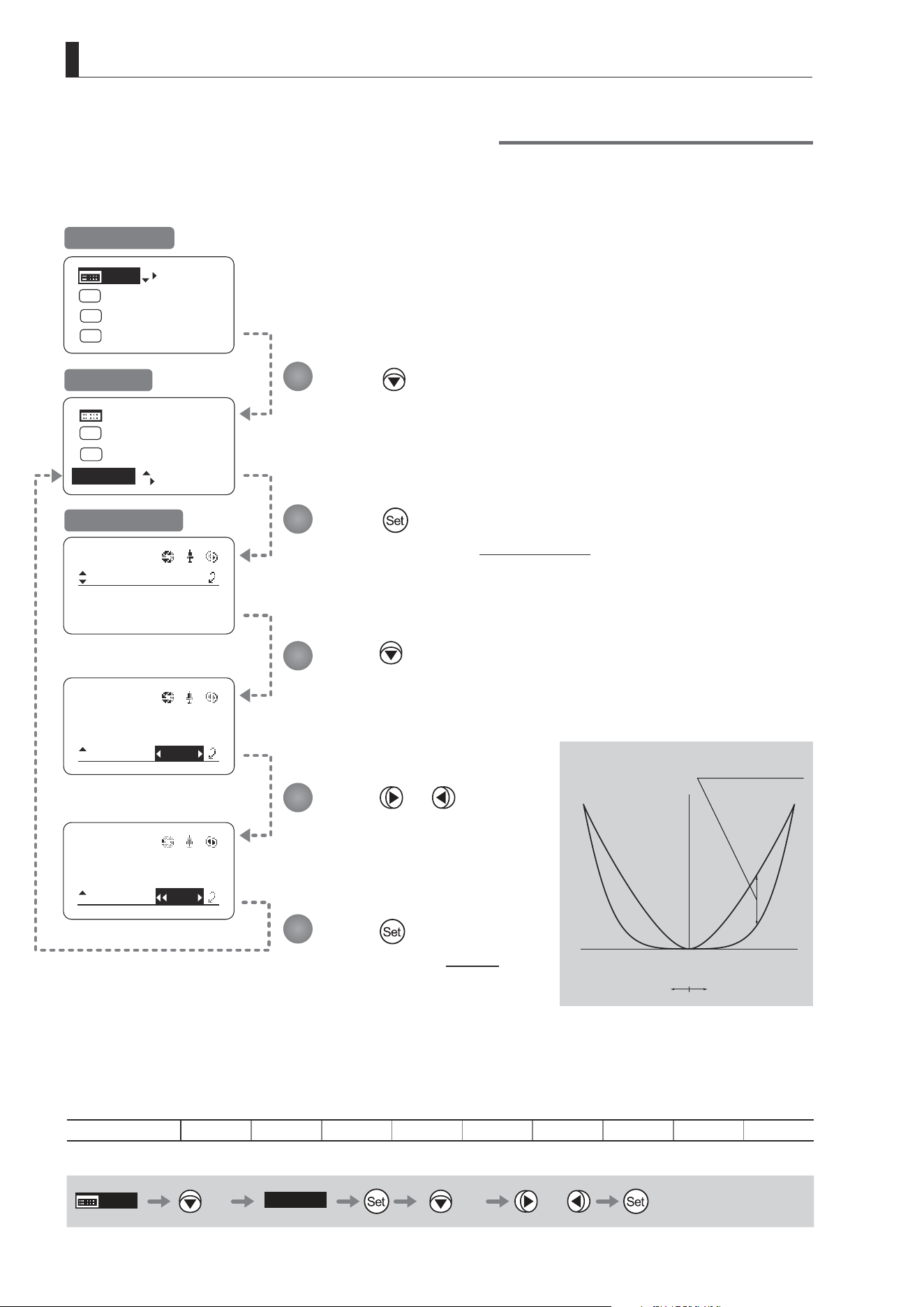
3. Operation in Basic Mode
CurveMode
Zoom
Demand:
Seesaw:
5
5
[]
CurveMode
Zoom
Demand:
Seesaw:
]
[]
CurveMode
Zoom
Demand:
Seesaw:
D5
8
5
5
[]
[I-Tq]H
[Z.M.]
A 2
Fr1P
MENU
[Trk]
OFF
Shtl
A 1
IG: 50
[Trk]
OFF
Shtl
A 1
A 2
MENU
IG: 50
A
Fr1P
Fr1P
[I-Tq]H
[Adj]
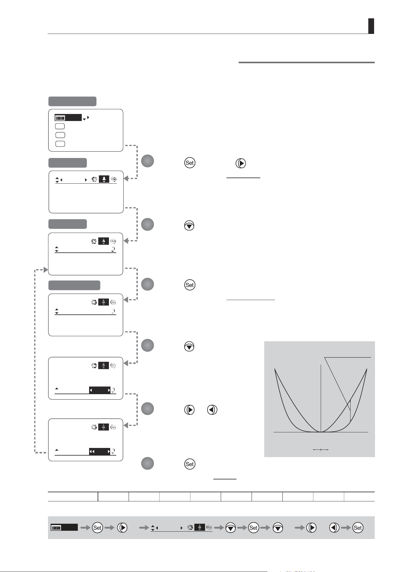
Press four times.
Your selection is now highlighted.
Press .
The display switches to the CurveMode screen.
Press twice.
[Demand] is underlined.
The default value is highlighted.
Press or .
Press left or right until you reach
the desired value.
Press .
The display reverts to Screen A.
Options 1 2 3 4
(D)
5 6 7 8 9
(D): Default value
MENU
× 4
[Z.M.]
× 2 or
Specifying Analog Demand Responsiveness
Congure the responsiveness of zoom speed adjustment in response to pressing the analog demand thumb ring.
(Note: Another screen is displayed when this setting is congured.)
1
2
3
4
5
Initial Top Screen
Screen A
CurveMode Screen
(1)
(9)
Responsiveness to
zoom mode adjustment
Maximum
Zoom Speed
Wide Angle Telephoto
Extent of tilting the analog demand
Zoom Direction
E33
3. Operation in Basic Mode
Iris
[]
[ I-Gain ]
Torque: High
Comp:ON
Fol.
Iris:
Zoom:
Focus:
0940
0527
0011
B
Frame1:
Preset
Zoom
Frame2: Zoom
ZSpeed: 800
: Go Top
: Back
Set
Set
1
2
3
4
5
6
7
8
]
CurveMode
Focus
[]
Mode:
User
Basic
Access:
ResetAll
B
Unlock
Switch
B
AUX2:
A
A 1
AUX1:
A 2
Fr1P
AUX:
Fr1P
Shtl
CurveMode
VR-Dem: ON
Zoom
[]
Info
Encoder:
OFF
S/N
3D:
OFF
[Trk]
OFF
Shtl
A 1
A 2
MENU
IG: 50
A
Fr1P
Fr1P
[I-Tq]H
[Adj]
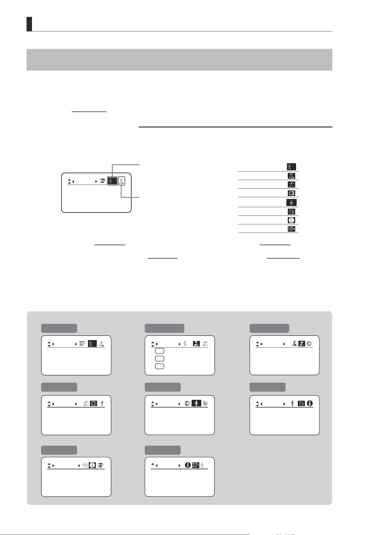
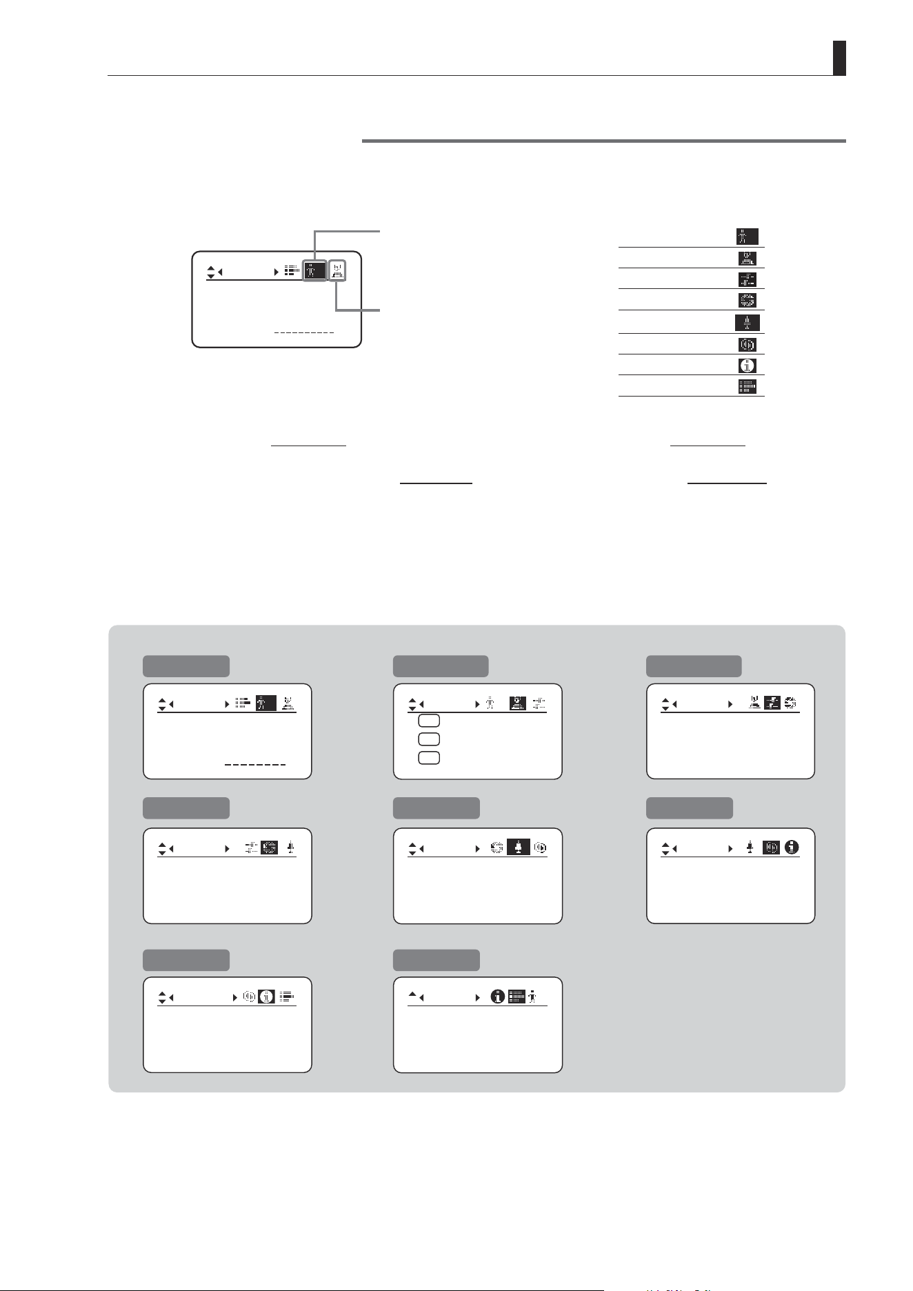
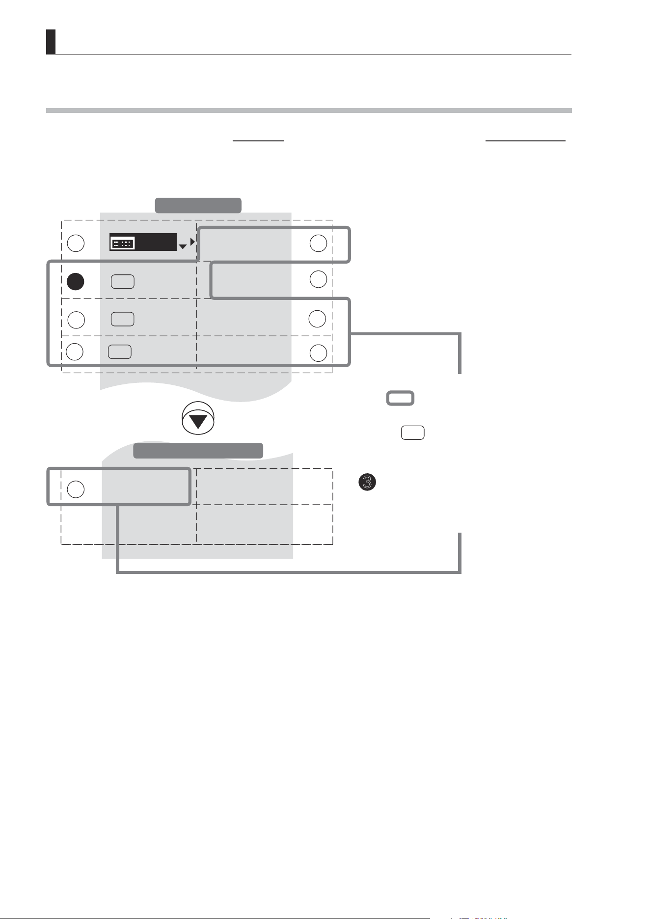
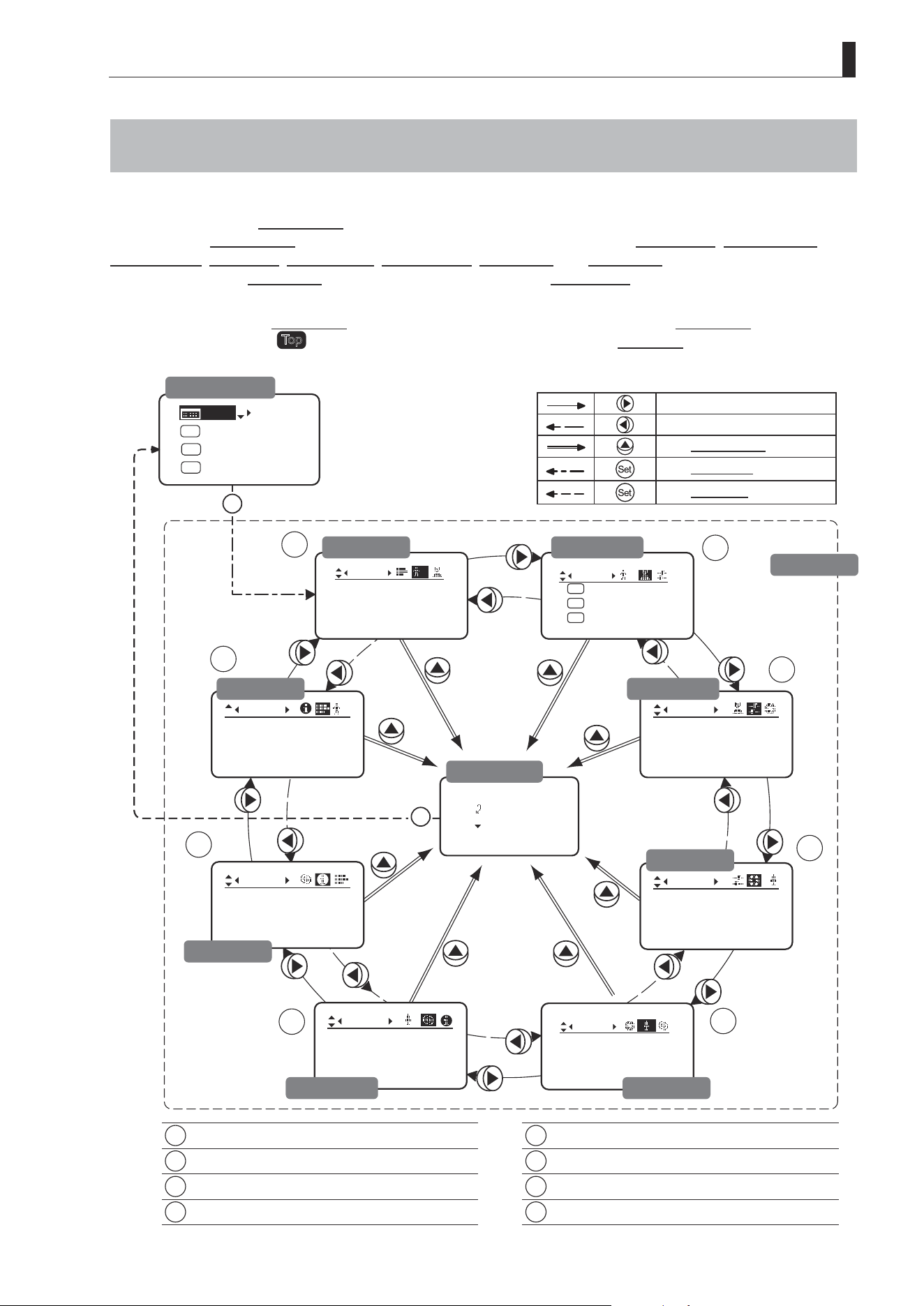
3.2 Conguration from the Menu Screen
In Basic mode, you can view and congure 22 setting items and a “follow” screen with three setting items that have
relative values from the Menu screen.*
Specically, the Menu screen in Basic mode is organized into 8 screens by function: User screen, Switch screen,
Preset screen, Iris screen, Zoom screen, Focus screen, Info screen, and Fol. screen.
Select [MENU] on the Top screen and press the Set key to access the User screen initially. Press left or right to access
the 7 other screens. (See the following gure.)
*: There is no single Menu screen. Instead, these 8 screens are collectively referred to as the Menu screen.
Setting items labeled
Top
next to the function title can also be congured from the Top screen.
1
User Screen................................................ 3.2.1
5
Zoom Screen .............................................. 3.2.5
2
Switch Screen............................................. 3.2.2
6
Focus Screen ............................................. 3.2.6
3
Preset Screen ............................................. 3.2.3
7
Info Screen ................................................. 3.2.7
4
Iris Screen .................................................. 3.2.4
8
Fol. Screen ................................................. 3.2.8
To the next screen clockwise
To the next screen counterclockwise
To the Go Top screen
To the User screen
To the Top screen
Initial Top Screen
User Screen
Fol. Screen
Go Top Screen
Preset Screen
Switch Screen
Menu Screen
Iris Screen
Zoom ScreenFocus Screen
Info Screen

E34
3. Operation in Basic Mode
3.2.1 User Screen Settings
User B is the user in Basic mode.
The following setting items can be congured on the User Screen.
Switching Modes
Resetting Values
Locking Functions
Mode:
User
Basic
Access:
ResetAll
B
Unlock
User Screen in Basic Mode
E35
3. Operation in Basic Mode
Mode:
User
Basic
Access:
ResetAll
B
Unlock
Mode:
User
Basic
Access:
ResetAll
B
Unlock
No. :
User
1
Name:
Mode:
1
Full
[Trk]
OFF
Shtl
A 1
A 2
MENU
IG: 50
A
Fr1P
Fr1P
[I-Tq]H
[Adj]
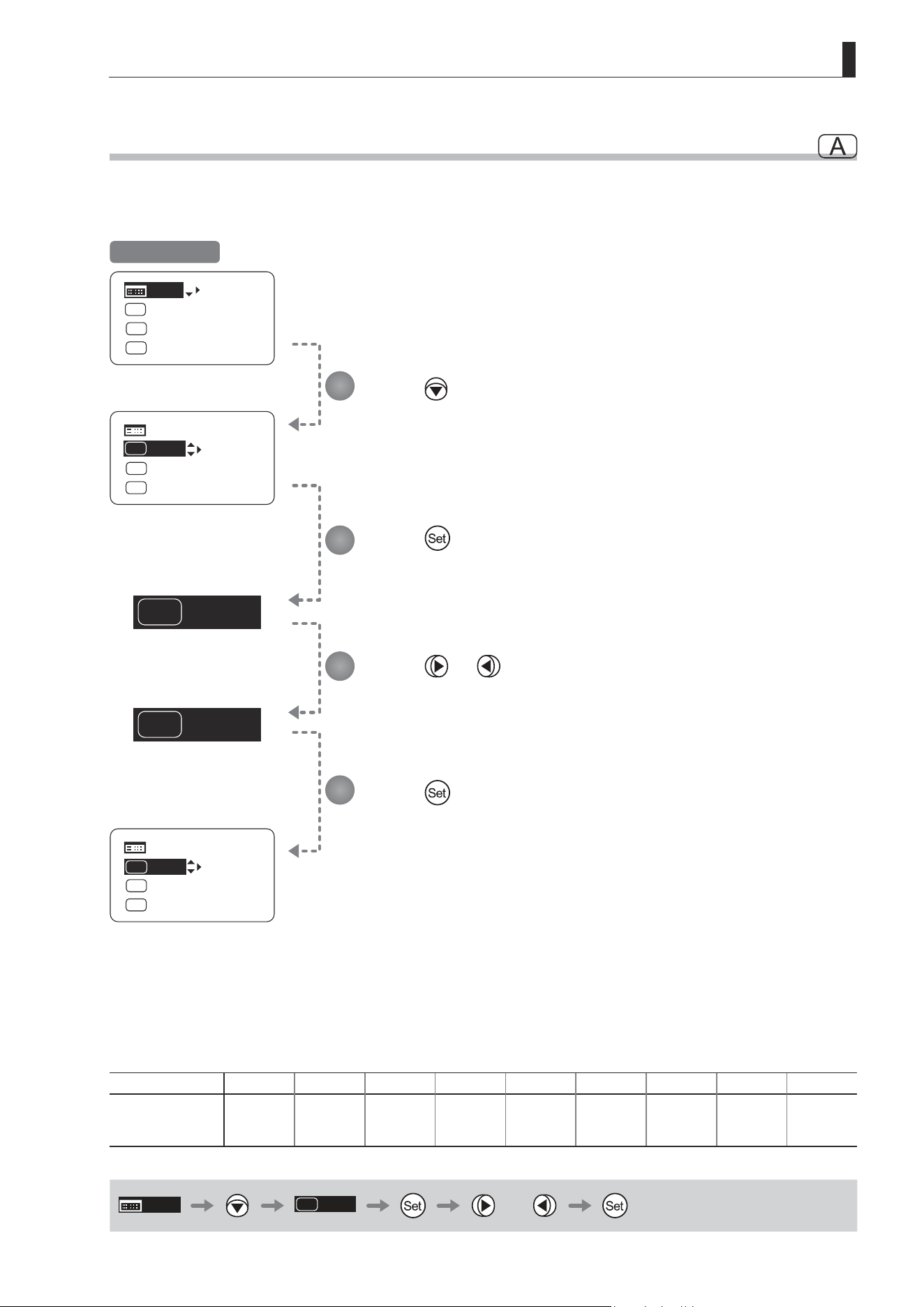
Switching Modes
Switch to Full or Analog mode as needed.
Important
The new mode setting is retained even after the lens is turned o.
Press .
The display switches to the User screen.
Press .
[Mode] is underlined.
The previous mode is highlighted.
Press or .
Press left or right until you reach the desired mode.
Options
(D)
Basic Full Analog
Save Settings Basic Mode Full Mode Analog Mode
(D): Default value
MENU
User
B
or
1
2
3
Initial Top Screen
User Screen
E36
3. Operation in Basic Mode
User B
Reset Now.
ResetAll
User
User:
y/n
Mode:
User
Basic
Access:
ResetAll
B
Unlock
ResetAll
User
User:
y/n
Mode:
User
Basic
Access:
ResetAll
B
Unlock
Mode:
User
Basic
Access:
ResetAll
B
Unlock
B
B
[Trk]
OFF
Shtl
A 1
A 2
MENU
IG: 50
A
Fr1P
Fr1P
[I-Tq]H
[Adj]
MENU
User
B
× 2
Resetting Values
Reset a user’s settings to default values as needed.
Note: Iris gain values are not reset.
The current value is retained.
Press and then .
Press .
The display switches to the User screen.
Press twice.
[ResetAll] is underlined.
Press .
The display switches to
the Reset screen.
Press .
A conrmation message is displayed about resetting information for the selected
user.
Note: You can cancel resetting and
restore the original values
at any time before pressing
in step 5. To return to the
previous screen, press up. To
cancel resetting and turn o
the display, press the Display
switch.
User Screen
Title: Reset
Title: Reset
Reset Screen
1
2
3
4
5
Initial Top Screen
After a message is displayed indicating that resetting is in progress, the display
reverts to Title: Reset.
The settings have now been reset.
E37
3. Operation in Basic Mode
(1) Locking Settings
User
B
Access:
Unlock
Mode:
User
Basic
Access:
ResetAll
B
Unlock
Mode: Basic
ResetAll
[Trk]
OFF
Shtl
A 1
A 2
MENU
IG: 50
A
Fr1P
Fr1P
[I-Tq]H
[Adj]
Locking Functions
To ensure that congured functions cannot easily be changed, you can lock the settings of certain functions.
Mode:
User
Basic
Access:
ResetAll
B
Unlock
Mode:
User
Basic
Access:
ResetAll
B
Lock
Unlocked Locked
Note
In lock mode, only the following items can still be congured, and other settings are locked.
• Preset data (Shuttle shot position, Frame preset position, Preset speed)
• Auto iris gain setting
Press .
The display switches to the User screen.
Press three times.
The previous or default value is highlighted.
Press .
Initial Top Screen
User Screen
Continued on next page
1
2
3
E38
3. Operation in Basic Mode
EnterPassword
EnterPassword
Lock OK?
y/n
User
B
Access:
Lock
Mode: Basic
ResetAll
Enter the password and press .
Entering Passwords
Press up/down to nd characters and left/right to move the cursor or make corrections.
Be careful not to press the Set key until you are nished entering the password.
Press and then .
The settings are now locked.
Note
Passwords
No master password is used on this model. The password you enter each time to lock settings is the password used
to unlock them. For this reason, we recommend making a note of the password each time. If you forget the password,
contact Canon or your dealer. Passwords can be blank or up to 8 digits.
Characters supported in passwords
Options
(D)
_– A B C D E F G H I J K L M N O P Q R S T U V W X Y Z a b c d e f g h i j k l m n o p q r s t u v w x y z 0 1 2 3 4 5 6 7 8 9
Max. Digits 8
(D) : Default value
_ : Space
Options
(D)
Unlock Lock
(D): Default value
MENU
× 3 Entering Passwords
DISPLAY
4
5
Continued from previous page
E39
3. Operation in Basic Mode
User
B
Mode: Basic
ResetAll
Access:
Lock
EnterPassword
Unlock OK?
y/n
Access:
Unlock
Mode:
User
Basic
Access:
ResetAll
B
Lock
User
B
Mode: Basic
ResetAll
EnterPassword
[Trk]
OFF
Shtl
A 1
A 2
MENU
IG: 50
A
Fr1P
Fr1P
[I-Tq]H
[Adj]
(2) Unlocking Settings
Press .
The display switches to the User screen.
Press three times.
The previous or default value is highlighted.
Enter the password and press .
The password you entered to lock settings is the password used to unlock them.
Press .
Press
and then .
The settings are now unlocked.
Options
(D)
Unlock Lock
(D): Default value
MENU
× 3 Entering Passwords
DISPLAY
Initial Top Screen
User Screen
1
2
3
4
5

E40
3. Operation in Basic Mode
3.2.2 Switch Screen Settings
The following setting items can be congured on the Switch screen.
Assigning Functions to the AUX Switch
Top
Assigning Functions to the AUX1 Switch
Top
Assigning Functions to the AUX2 Switch
Top
Items labeled
Top
can also be modied from the Top screen.
E41
3. Operation in Basic Mode
Fr1P
Switch
B
AUX2:
A
A 1
AUX1:
A 2
Fr1P
AUX:
Fr1P
Shtl
Switch
B
AUX2:
A
A 1
AUX1:
A 2
AUX:
Fr1P
Shtl
VTR
Switch
B
AUX2:
A
A 1
AUX1:
A 2
AUX:
Fr1P
Shtl
[Trk]
OFF
Shtl
A 1
A 2
MENU
IG: 50
A
Fr1P
Fr1P
[I-Tq]H
[Adj]
Press and then .
The display switches to the Switch screen.
Press .
[AUX] is underlined.
The previous or default function is highlighted.
Press or .
Press left or right until you reach the desired function.
Assigning Functions to the AUX Switch
Top
The AUX switch can be programmed to activate a function of your choice.
Initial Top Screen
Switch Screen
Options
(D)
Fr1P Fr1F Fr2P Fr2F Sped Shtl NON VTR RET
Description
Framing Preset1
switch
(preset speed)
Framing Preset1
switch
(max. speed)
Framing Preset2
switch
(preset speed)
Framing Preset2
switch
(max. speed)
Speed Preset
switch
Shuttle-Shot
switch
No function VTR switch RET switch
(D): Default value
MENU
Switch
B
or
1
2
3
E42
3. Operation in Basic Mode
Switch
B
AUX2:
A
A 1
AUX1:
A 2
Fr1P
AUX:
Fr1P
Shtl
Switch
B
AUX2:
A
A 1
AUX1:
A 2
AUX:
Fr1P
Shtl
Fr1P
Switch
B
AUX2:
A
A 1
AUX1:
A 2
AUX:
Fr1P
VTR
Fr1P
[Trk]
OFF
Shtl
A 1
A 2
MENU
IG: 50
A
Fr1P
Fr1P
[I-Tq]H
[Adj]
Assigning Functions to the AUX1 Switch
Top
The AUX1 switch for a zoom demand can be programmed to activate a function of your choice.
Press and then .
The display switches to the Switch screen.
Press twice.
[AUX1] is underlined.
The previous or default function is highlighted.
Press or .
Press left or right until you reach the desired function.
Initial Top Screen
Switch Screen
Options Fr1P Fr1F Fr2P Fr2F Sped
(D)
Shtl NON VTR RET
Description
Framing Preset1
switch
(preset speed)
Framing Preset1
switch
(max. speed)
Framing Preset2
switch
(preset speed)
Framing Preset2
switch
(max. speed)
Speed Preset
switch
Shuttle-Shot
switch
No function VTR switch RET switch
(D): Default value
MENU
Switch
B
× 2 or
1
2
3
E43
3. Operation in Basic Mode
Switch
B
AUX2:
A
A 1
AUX1:
A 2
Fr1P
AUX:
Fr1P
Shtl
Switch
B
AUX2:
A
A 1
AUX1:
A 2
AUX:
Shtl
Fr1P
Fr1P
Switch
B
AUX2:
A
A 1
AUX1:
A 2
AUX:
Shtl
Fr1P
Sped
[Trk]
OFF
Shtl
A 1
A 2
MENU
IG: 50
A
Fr1P
Fr1P
[I-Tq]H
[Adj]
Assigning Functions to the AUX2 Switch
Top
The AUX2 switch for a zoom demand can be programmed to activate a function of your choice.
Press and then .
The display switches to the Switch screen.
Press three times.
[AUX2] is underlined.
The previous or default function is highlighted.
Press or .
Press left or right until you reach the desired function.
Initial Top Screen
Switch Screen
Options
(D)
Fr1P Fr1F Fr2P Fr2F Sped Shtl NON VTR RET
Description
Framing Preset1
switch
(preset speed)
Framing Preset1
switch
(max. speed)
Framing Preset2
switch
(preset speed)
Framing Preset2
switch
(max. speed)
Speed Preset
switch
Shuttle-Shot
switch
No function VTR switch RET switch
(D): Default value
MENU
Switch
B
× 3 or
1
2
3

E44
3. Operation in Basic Mode
3.2.3 Preset Screen Settings
The following setting items can be congured on the Preset screen.
Switching What Frame Preset 1 Controls
Switching What Frame Preset 2 Controls
Specifying the Preset Mode Zoom Speed
E45
3. Operation in Basic Mode
Frame1:
Preset
Zoom
Frame2: Zoom
ZSpeed: 800
Frame1:
Preset
Zoom
Frame2: Zoom
ZSpeed: 800
Frame1:
Preset
Focus
Frame2: Zoom
ZSpeed: 800
[Trk]
OFF
Shtl
A 1
A 2
MENU
IG: 50
A
Fr1P
Fr1P
[I-Tq]H
[Adj]
Press once and twice.
The display switches to the Preset screen.
Press .
[Frame1] is underlined.
The previous or default value is highlighted.
Press or .
Switching What Frame Preset 1 Controls
Switch what frame preset 1 controls, as needed.
Zoom : Move the zoom position to the position in memory
Focus : Move the focus position to the position in memory
Z+F : Move the zoom and focus position to the position in memory
Initial Top Screen
Preset Screen
Screen A
Frame1 Screen
Options
(D)
Zoom Focus Z+F
Description Control zooming Control focusing Control zooming and focusing
(D): Default value
MENU
× 2
Preset
or
1
2
3
E46
3. Operation in Basic Mode
Frame1:
Preset
Zoom
Frame2: Zoom
ZSpeed: 800
Frame1:
Preset
Frame2:
Zoom
ZSpeed: 800
Frame1:
Preset
Frame2:
Zoom
ZSpeed: 800
Zoom
Focus
[Trk]
OFF
Shtl
A 1
A 2
MENU
IG: 50
A
Fr1P
Fr1P
[I-Tq]H
[Adj]
Press once and twice.
The display switches to the Preset screen.
Press twice.
[Frame2] is underlined.
The previous or default value is highlighted.
Press or .
Switching What Frame Preset 2 Controls
Switch what frame preset 2 controls, as needed.
Zoom : Move the zoom position to the position in memory
Focus : Move the focus position to the position in memory
Z+F : Move the zoom and focus position to the position in memory
Initial Top Screen
Preset Screen
Screen A
Frame2 Screen
Options
(D)
Zoom Focus Z+F
Description Control zooming Control focusing Control zooming and focusing
(D): Default value
MENU
× 2
Preset
× 2 or
1
2
3
E47
3. Operation in Basic Mode
Frame1:
Preset
Zoom
Frame2: Zoom
ZSpeed: 800
Frame1:
Preset
Zoom
Frame2: Zoom
ZSpeed:
800
500
Frame1:
Preset
Zoom
Frame2: Zoom
ZSpeed:
[Trk]
OFF
Shtl
A 1
A 2
MENU
IG: 50
A
Fr1P
Fr1P
[I-Tq]H
[Adj]
Press once and twice.
The display switches to the Preset screen.
Press three times.
[ZSpeed] is underlined.
The previous or default value is highlighted.
Press or .
Press left or right until you reach the desired value.
Specifying the Preset Mode Zoom Speed
Congure the zoom speed from any position to the position in memory, as needed.
To adjust the value, use either the Memo button (refer to the operation manual "Lens") or display operations.
Regardless of the method of adjustment used, the most recent setting takes precedence.
Initial Top Screen
Preset Screen
Note: Your specied values apply to
both Fr1P and Fr2P.
Options 1 to
(D)
800
Description Slowest Fastest
(D): Default value
MENU
× 2
Preset
× 3 or
1
2
3

E48
3. Operation in Basic Mode
3.2.4 Iris Screen Settings
The following setting items can be congured on the Iris screen.
Specifying Iris Gain
(1) Specifying Auto Iris Gain
Top
(2) Specifying Remote Iris Gain
Specifying Iris Torque
Top
Iris Compensation ON/OFF
Iris Close Detection ON/OFF
Focus Demand Iris Control ON/OFF
Items labeled
Top
can also be modied from the Top screen.
E49
3. Operation in Basic Mode
[ I-Gain ]
Iris
Remote:
90
Auto:
50
[]
[ I-Gain ]
Iris
Remote:
90
Auto:
55
[]
Iris
[]
[ I-Gain ]
Torque: High
Comp: ON
[ I-Gain ]
Iris
Remote:
90
Auto:
50
[]
[ I-Gain ]
Iris
Comp: ON
Torque: High
[]
[Trk]
OFF
Shtl
A 1
A 2
MENU
IG: 50
A
Fr1P
Fr1P
[I-Tq]H
[Adj]
Specifying Iris Gain
(1) Specifying Auto Iris Gain
Top
Although this value is factory-set, it can be adjusted as needed.
To adjust the value, use either the auto iris gain adjustment trimmer (refer to the operation manual "Lens") or display
operations. Regardless of the method of adjustment used, the most recent setting takes precedence.
The same auto iris gain value applies to all users.
Note: Do the following when
adjusting gain while checking
iris operation.
→ Conrm that the drive unit A/M
switch is set to [Auto] mode.
→ Set the camera iris mode to
[Auto].
Note: As you look at the lens iris
ring, set it to the position of
maximum gain at which “focus
hunting” does not occur.
Note: The current iris gain value
is retained even if you reset
other settings as described in
“3.2.1 Resetting Values.” For
this reason, you will no longer
be able to view the default
setting. If necessary, make
a note of the default setting
before adjusting this value.
Press once and
three times.
The display switches to the Iris screen.
Press .
[I-Gain] is underlined.
Press .
The display switches to the [I-Gain] screen.
Press .
The display reverts to Screen A.
Press .
[Auto] is underlined.
The previous or default value is highlighted.
Press or .
Press left or right until you reach the desired function.
Initial Top Screen
Iris Screen
Screen A
[I-Gain] Screen
Options 01 to 99
Default: Varies depending on the factory-set value, but corresponds to
the value determined with the iris gain adjustment trimmer.
Description Minimum gain Maximum gain
MENU
× 3
Iris
[ ]
or
1
2
3
4
5
6
E50
3. Operation in Basic Mode
52
[ I-Gain ]
Iris
Remote:
90
Auto:
50
[]
[ I-Gain ]
Iris
Remote:
93
Auto:
50
[]
Iris
[]
[ I-Gain ]
Torque: High
Comp: ON
[ I-Gain ]
Iris
Remote:
90
Auto:
50
[]
[ I-Gain ]
Iris
Comp: ON
Torque: High
[]
[Trk]
OFF
Shtl
A 1
A 2
MENU
IG: 50
A
Fr1P
Fr1P
[I-Tq]H
[Adj]
(2) Specifying Remote Iris Gain
Although this value is factory-set, it can be adjusted as needed.
The same remote iris gain value applies to all users.
Note: Do the following when
adjusting gain while checking
iris operation.
→ Conrm that the drive unit A/M
switch is set to [Auto] mode.
→ Set the camera iris mode to
[Remote].
Note: The current iris gain value
is retained even if you reset
other settings as described in
“3.2.1 Resetting Values.” For
this reason, you will no longer
be able to view the default
setting. If necessary, make
a note of the default setting
before adjusting this value.
Press once and
three times.
The display switches to the Iris screen.
Press .
[I-Gain] is underlined.
Press .
The display switches to the [I-Gain] screen.
Press .
The display reverts to Screen A.
Press twice.
[Remote] is underlined.
The previous or default value is highlighted.
Press or .
Press left or right until you reach the desired function.
Initial Top Screen
Iris Screen
Screen A
[I-Gain] Screen
Options 01 to 99
Description Minimum gain Maximum gain
Default value: 90
MENU
× 3
Iris
[ ]
× 2 or
1
2
3
4
5
6
E51
3. Operation in Basic Mode
[ I-Gain ]
Iris
[]
Torque:
Comp: ON
High
[ I-Gain ]
Iris
[]
Torque:
Comp: ON
Low
Iris
[]
[ I-Gain ]
Torque: High
Comp: ON
[Trk]
OFF
Shtl
A 1
A 2
MENU
IG: 50
A
Fr1P
Fr1P
[I-Tq]H
[Adj]
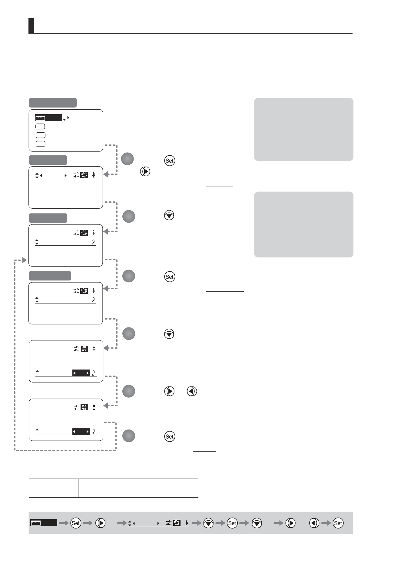
Specifying Iris Torque
Top
Specify the desired level of torque in manual control of the iris ring.
Press once and three times.
The display switches to the Iris screen.
Press twice.
[Torque] is underlined.
The previous or default function is highlighted.
Press or .
Press left or right to switch the function to {High} or {Low}.
Initial Top Screen
Iris Screen
Options
(D)
High Low
Description High torque Low torque
(D): Default value
MENU
× 3
Iris
[ ]
× 2 or
1
2
3
E52
3. Operation in Basic Mode
㧖
Iris
[]
[ I-Gain ]
Torque: High
Comp: ON
Iris
[]
Comp:
Close: OFF
Torque: High
ON
Iris
[]
Comp:
Torque: High
OFF
[Trk]
OFF
Shtl
A 1
A 2
MENU
IG: 50
A
Fr1P
Fr1P
[I-Tq]H
[Adj]
Controller OFF
Iris Compensation ON/OFF
The amount of light decreases when an extender (1.5×) is used. Therefore, you can set a function that corrects the iris to
the open side so as to maintain the amount of light.
Press once and three times.
The display switches to the Iris screen.
Press three times.
[Comp] is underlined.
The previous or default function is
highlighted.
Press or .
Press left or right to switch the function
{ON} or {OFF}.
Initial Top Screen
Iris Screen
Options
(D)
ON OFF
Description Iris compensation No iris compensation
(D): Default value
MENU
× 3
Iris
[ ]
× 3 or
Note: The iris may not fully close
in some cases when the iris
compensation is set to ON
while an extender (1.5×) is
used. If so, activate detection
as described in “Iris Close
Detection ON/OFF.”
*: Displayed when {Comp} is set to ON.
1
2
3
E53
3. Operation in Basic Mode
㧖
㧖
Iris
[]
[ I-Gain ]
Torque: High
Comp: ON
Iris
[]
Comp:
Torque: High
ON
Close:
OFF
Iris
[]
Comp:
Close:
Torque: High
ON
ON
[Trk]
OFF
Shtl
A 1
A 2
MENU
IG: 50
A
Fr1P
Fr1P
[I-Tq]H
[Adj]
Iris Close Detection ON/OFF
The iris cannot be fully closed when correction is active and an extender (1.5×) is used. As a countermeasure, you can
specify a function to detect iris close and close the iris as needed.
Press once and
three times.
The display switches to the Iris screen.
Press four times.
[Close] is underlined.
The previous or default function is
highlighted.
Press or .
Press left or right to switch the function
{ON} or {OFF}.
Initial Top Screen
Iris Screen
Options
(D)
OFF ON
Description No close detection Close detection
(D): Default value
MENU
× 3
Iris
[ ]
× 4 or
Note: With some cameras, iris
compensation may conict
with iris control by the
camera, preventing correct iris
operation. If so, deactivate iris
close detection.
Note: Iris close is detected only
when iris compensation is
enabled.
*: Displayed when {Comp} is set to ON.
1
2
3
E54
3. Operation in Basic Mode
㧖
Iris
[]
[ I-Gain ]
Torque: High
Comp: ON
Iris
[]
Comp: ON
Close:
Controller:
OFF
OFF
㧖
Iris
[]
Comp: ON
Close:
Controller
ON
OFF
[Trk]
OFF
Shtl
A 1
A 2
MENU
IG: 50
A
Fr1P
Fr1P
[I-Tq]H
[Adj]
Focus Demand Iris Control ON/OFF
Iris operations using a focus demand can be switched on or o.
Press once and three times.
The display switches to the Iris screen.
Press ve times.
[Controller] is underlined.
The previous or default function is
highlighted.
Press or .
Press left or right to switch the function {ON} or {OFF}.
Initial Top Screen
Iris Screen
Options ON
(D)
OFF
Description Iris controlled with focus demand Iris not controlled with focus demand
(D): Default value
MENU
× 3
Iris
[ ]
× 5 or
*: Displayed when {Comp} is set to ON.
1
2
3

E55
3. Operation in Basic Mode
3.2.5 Zoom Screen Settings
The following setting items can be congured on the Zoom screen.
Specifying Seesaw Switch Responsiveness
Specifying Analog Demand Responsiveness
Demand-Based Zoom Speed Adjustment ON/OFF
E56
3. Operation in Basic Mode
CurveMode
Zoom
Demand:
Seesaw:
[]
5
5
CurveMode
Zoom
[]
OFF
CurveMode
Zoom
Demand:
Seesaw:
[]
5
CurveMode
Zoom
Demand:
Seesaw:
[]
5
D5
7
CurveMode
VR-Dem: ON
Zoom
[]
VR-Dem: ON
[Trk]
OFF
Shtl
A 1
A 2
MENU
IG: 50
A
Fr1P
Fr1P
[I-Tq]H
[Adj]
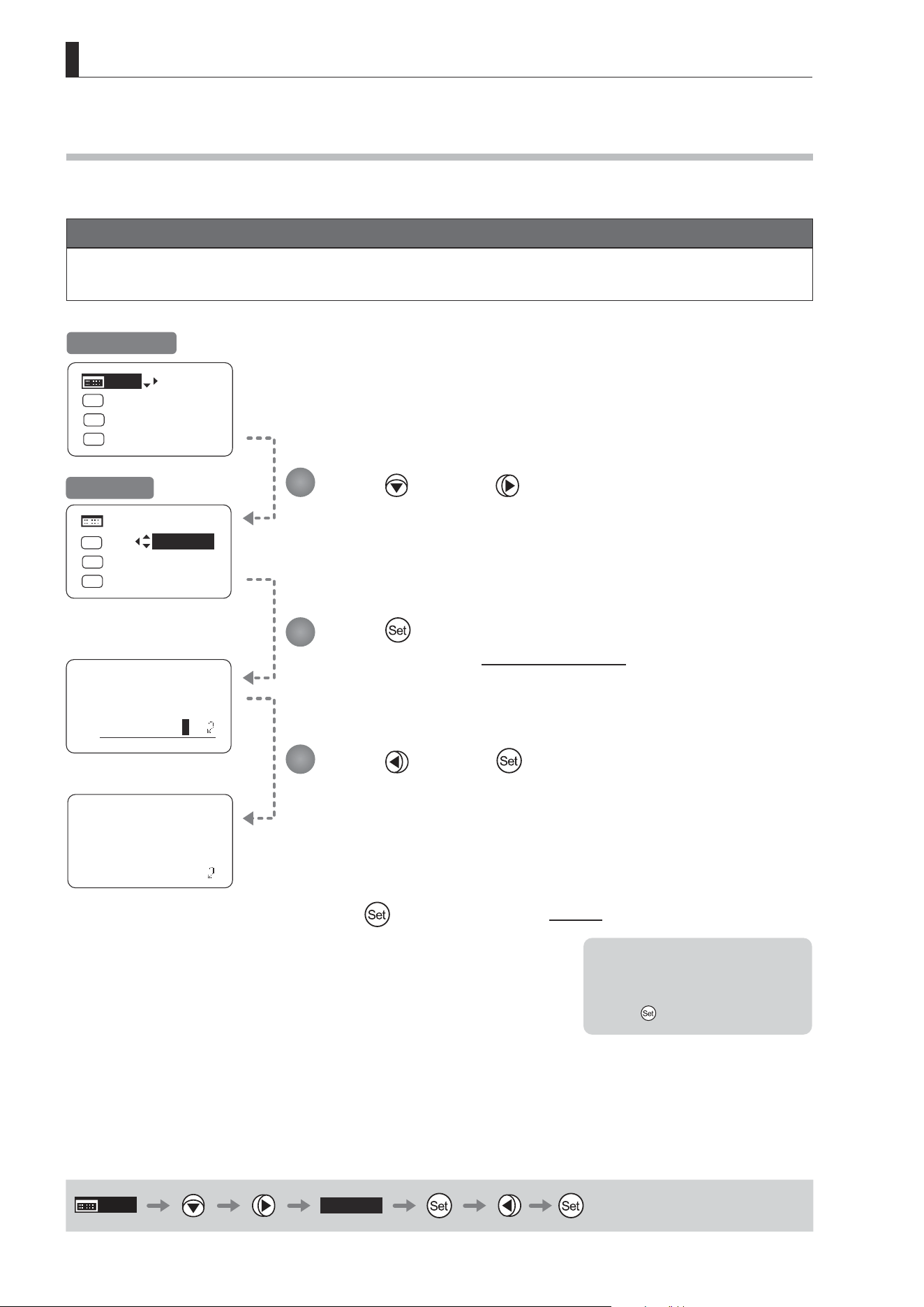
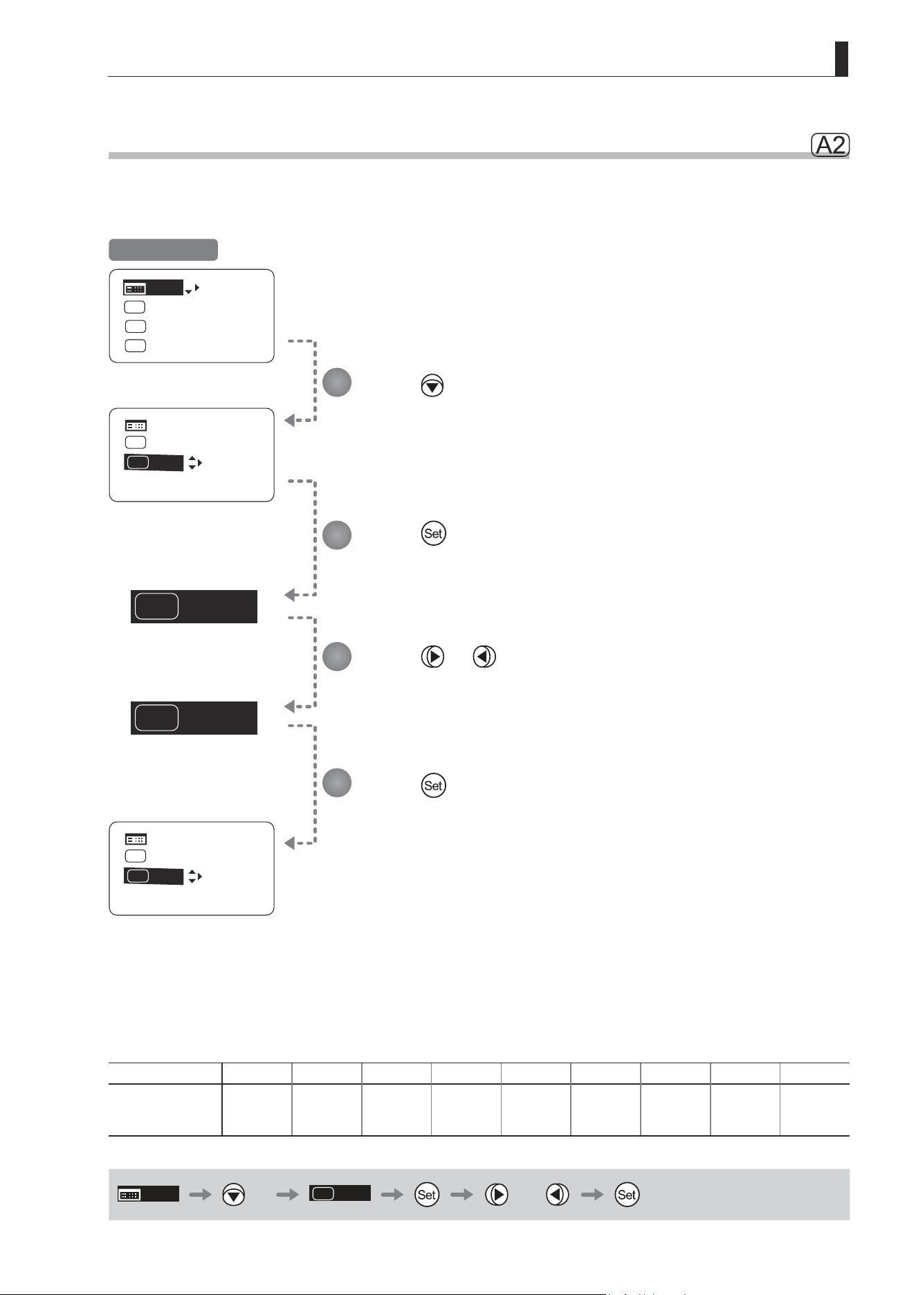
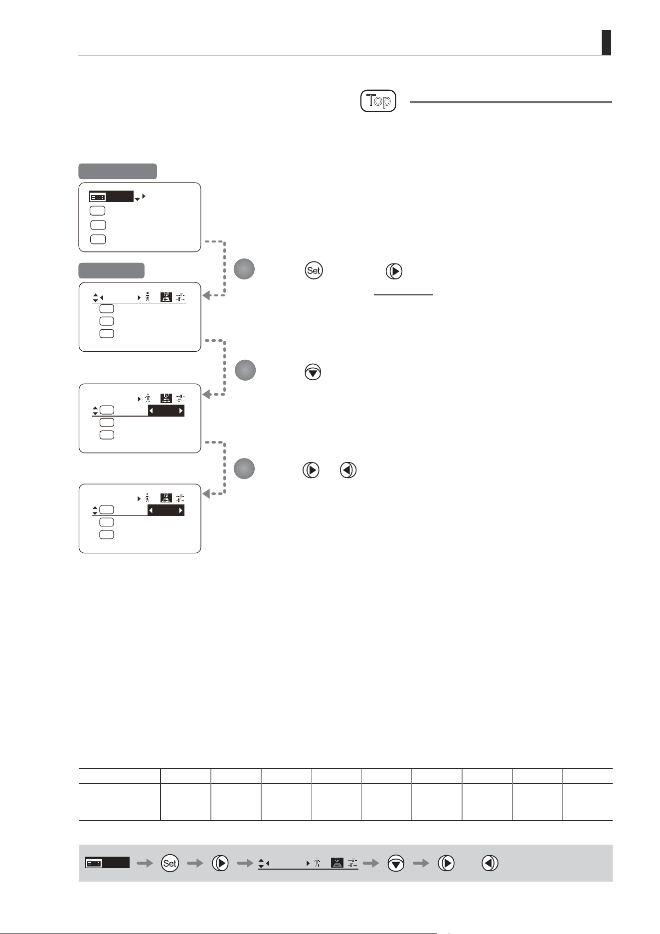
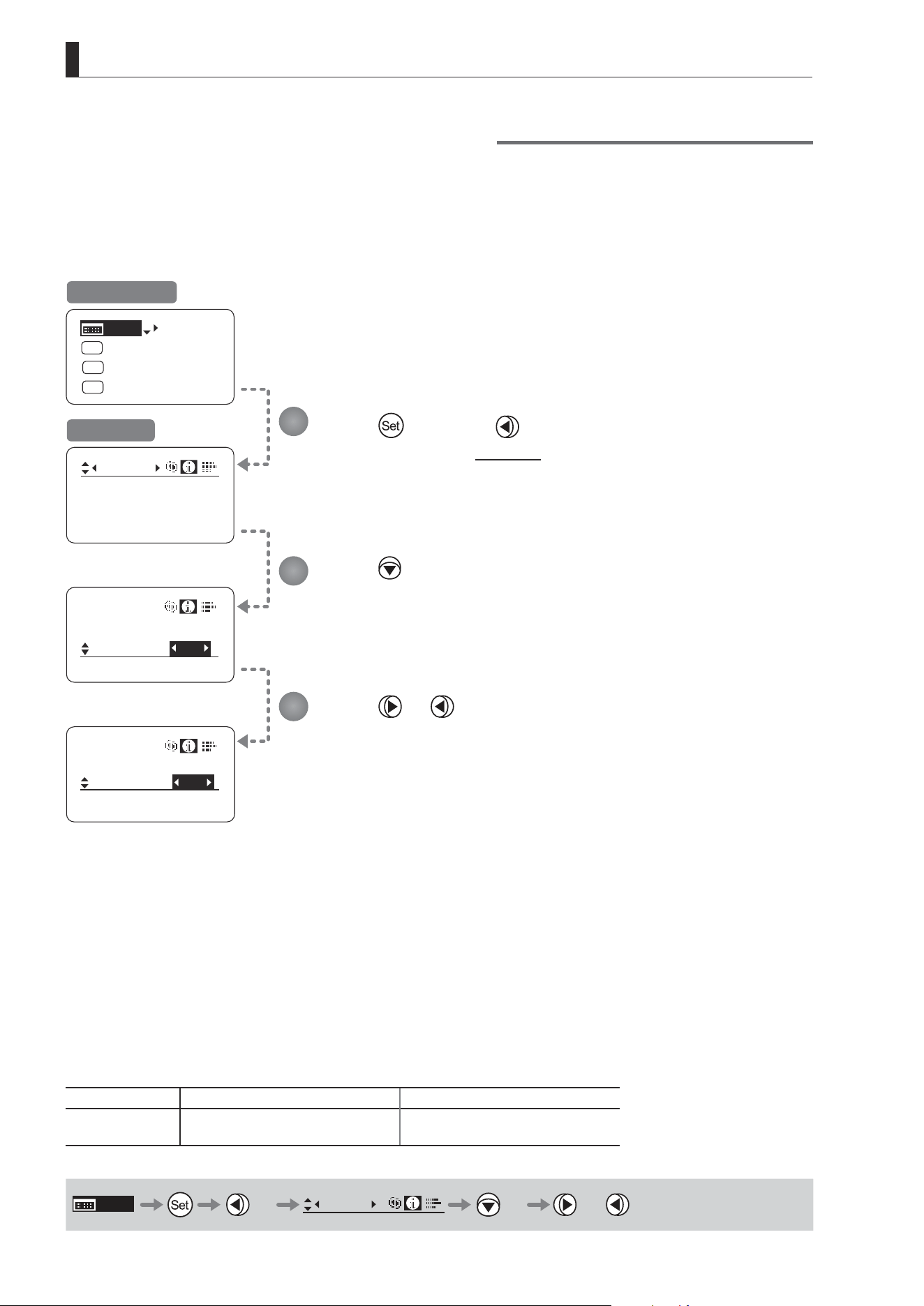
Specifying Seesaw Switch Responsiveness
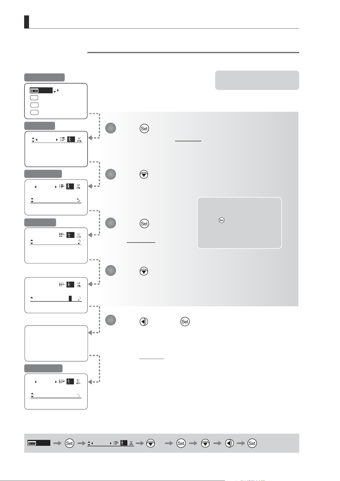
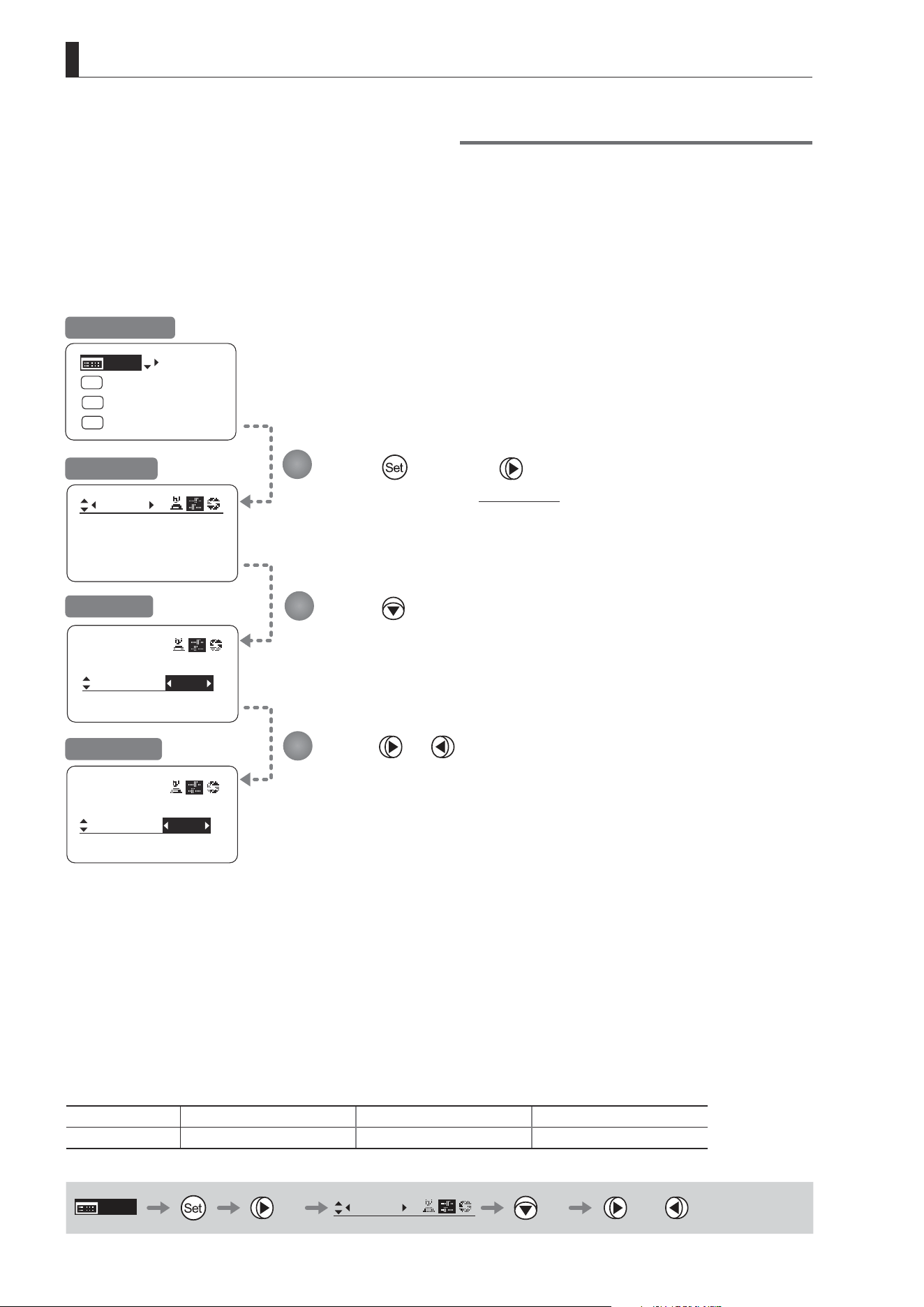
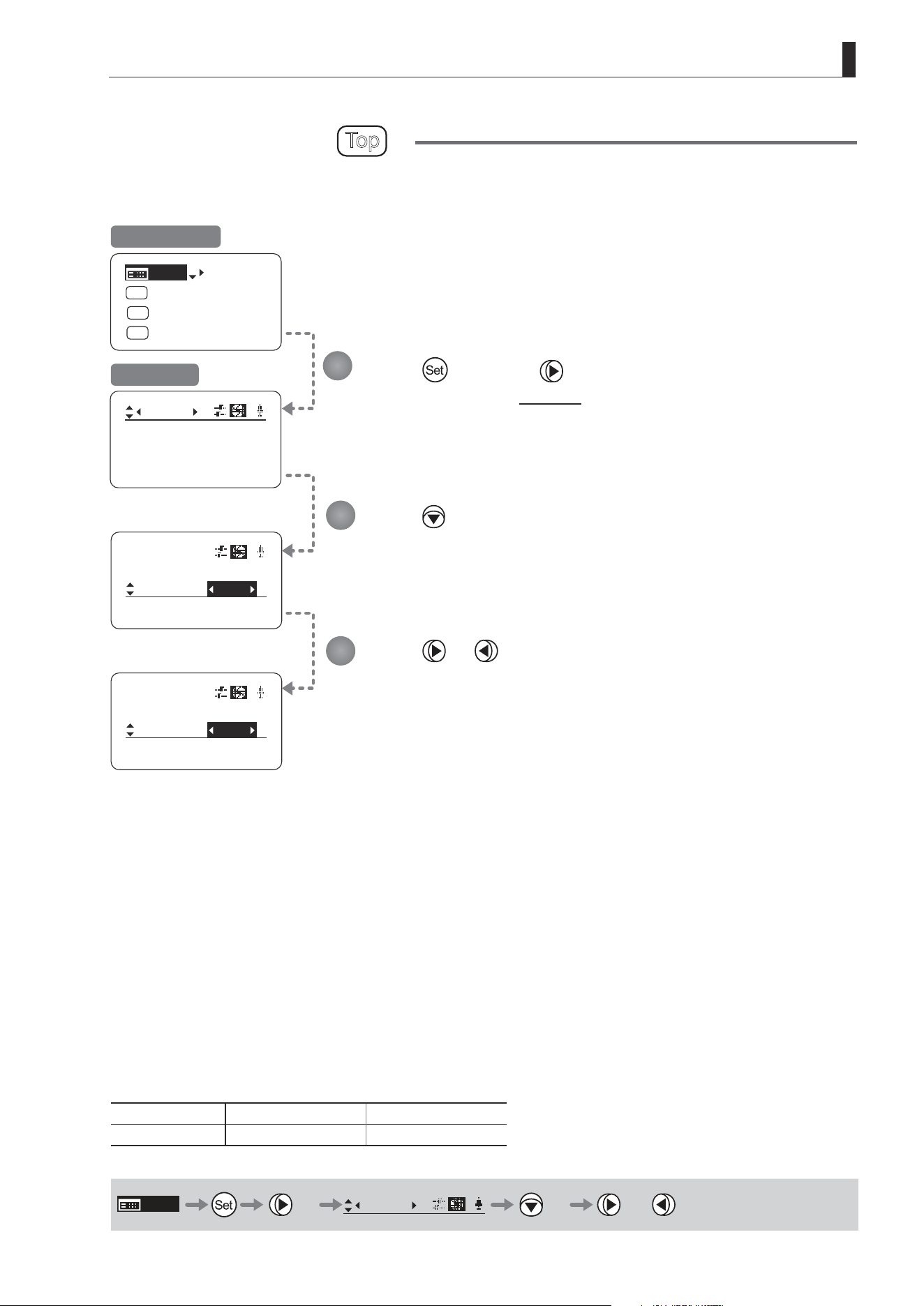
Congure the responsiveness of zoom speed adjustment in response to pressing the zoom seesaw switch.
(Note: Another screen is displayed when this setting is congured.)
Press once and four times.
The display switches to the Zoom screen.
Press or .
Press left or right until you reach
the desired function.
Press .
[CurveMode] is underlined.
Press .
[Seesaw] is underlined.
The previous or default value is
highlighted.
Press .
The display switches to the CurveMode screen.
Press .
The display reverts to Screen A.
Initial Top Screen
Zoom Screen
Screen A
CurveMode Screen
Options 1 2 3 4
(D)
5 6 7 8 9
(D): Default value
MENU
× 4
Zoom
[ ]
or
1
2
3
4
5
6
(1)
(9)
Responsiveness to
zoom mode adjustment
Maximum
Zoom Speed
Wide Angle Telephoto
Extent of pressing the zoom seesaw switch
Zoom Direction
E57
3. Operation in Basic Mode
CurveMode
Zoom
Demand:
Seesaw:
[]
5
5
CurveMode
Zoom
[]
OFF
VR-Dem: ON
CurveMode
VR-Dem: ON
Zoom
[]
CurveMode
Zoom
Demand:
Seesaw:
[]
5
CurveMode
Zoom
Demand:
Seesaw:
[]
5
D5
7
[Trk]
OFF
Shtl
A 1
A 2
MENU
IG: 50
A
Fr1P
Fr1P
[I-Tq]H
[Adj]
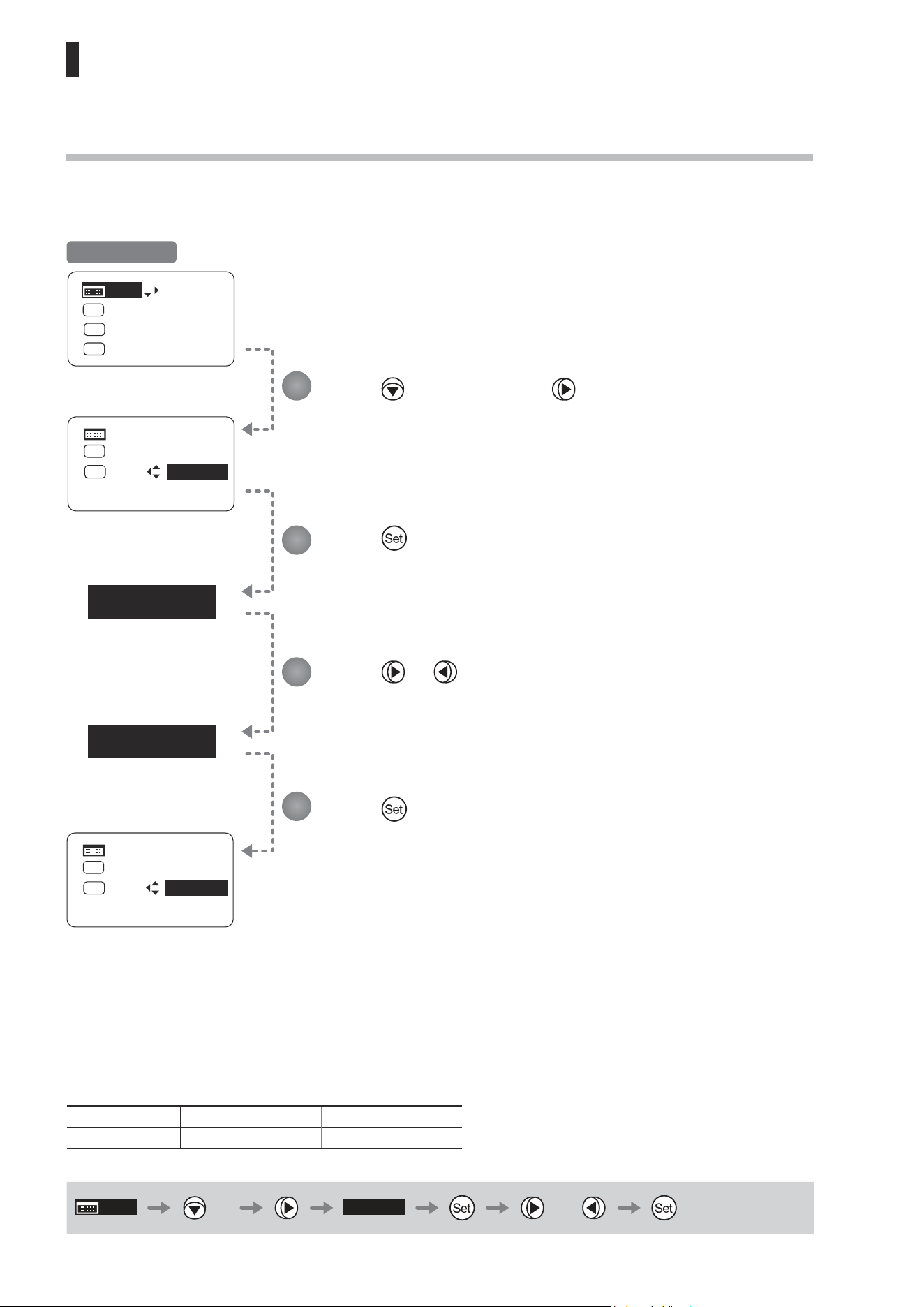
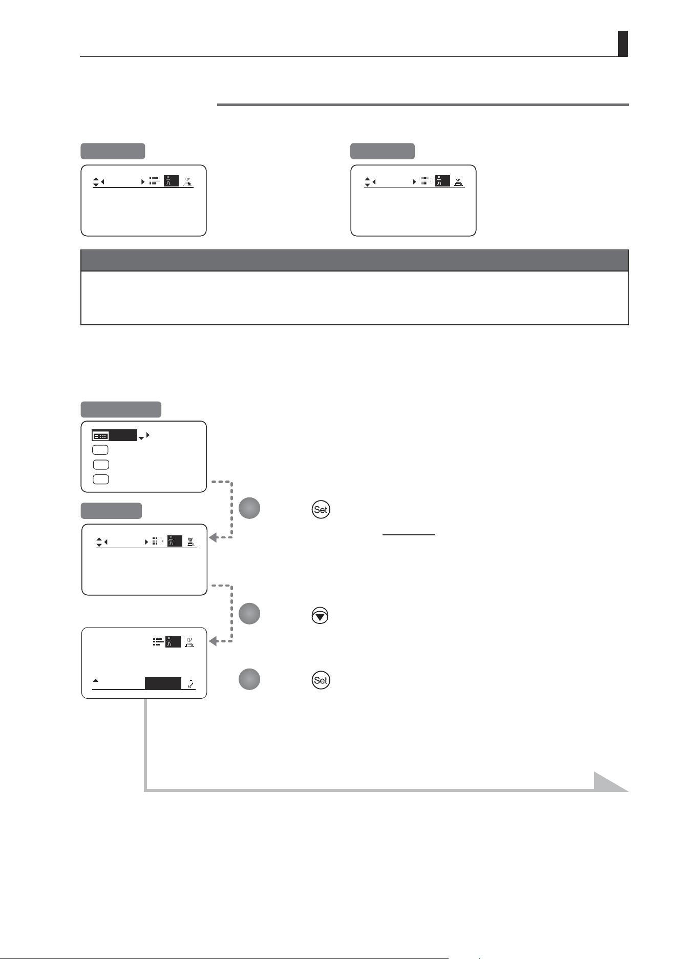
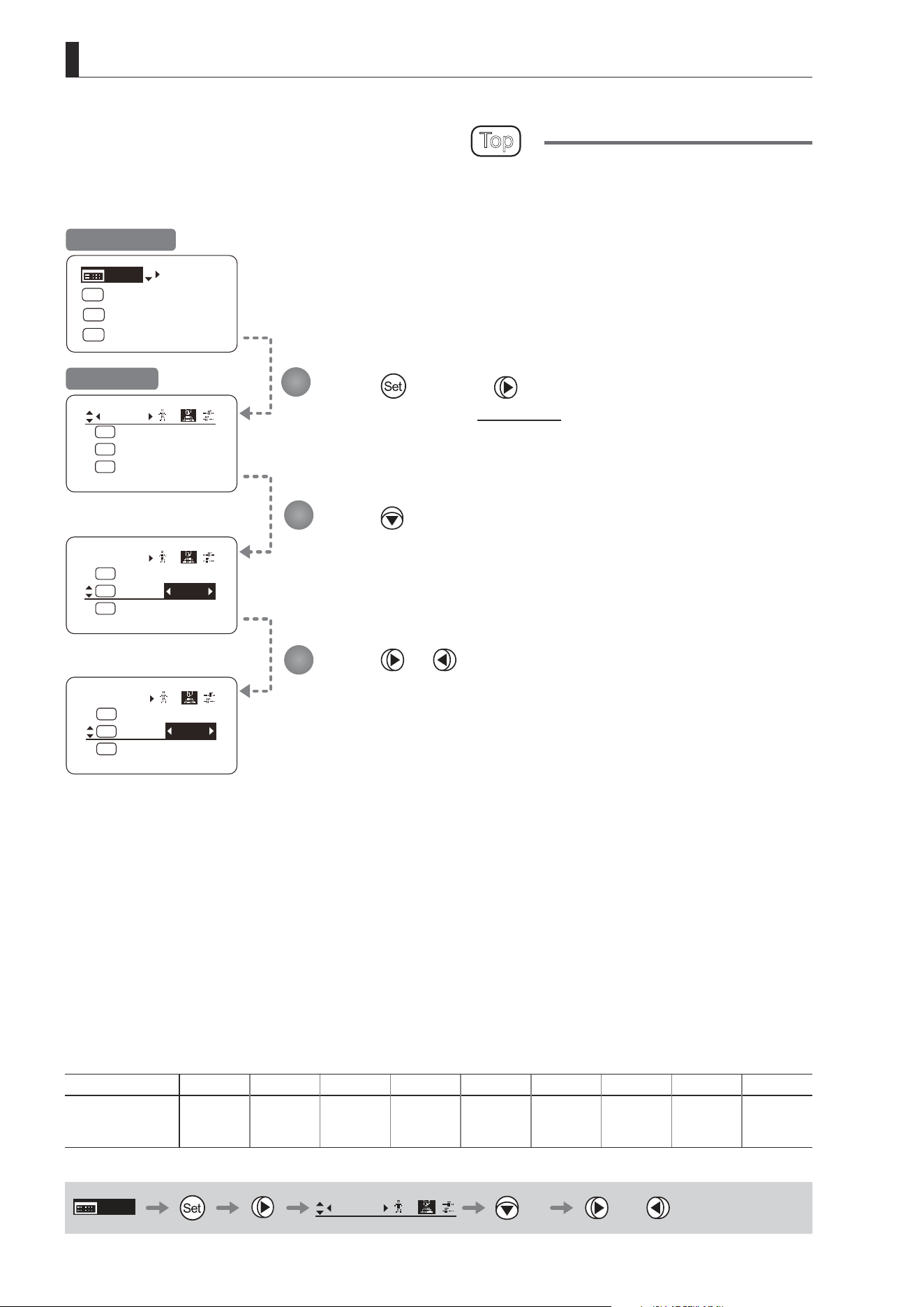
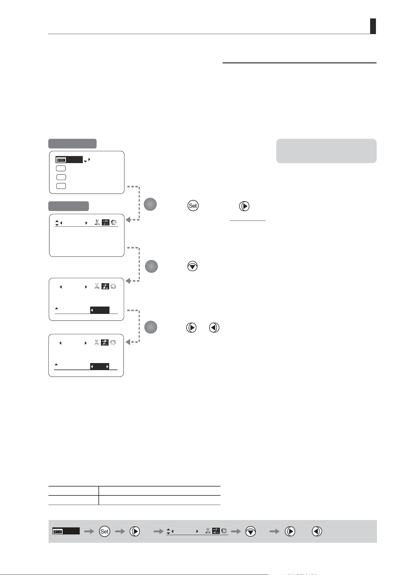
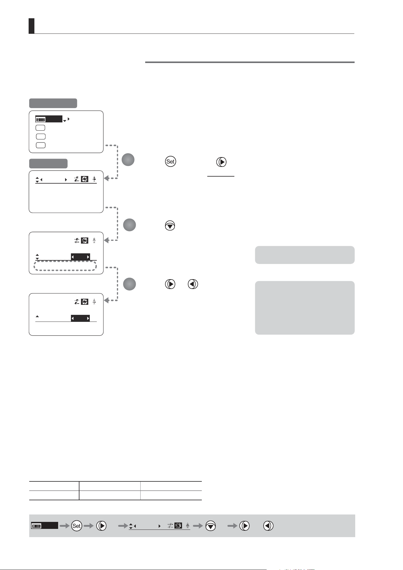
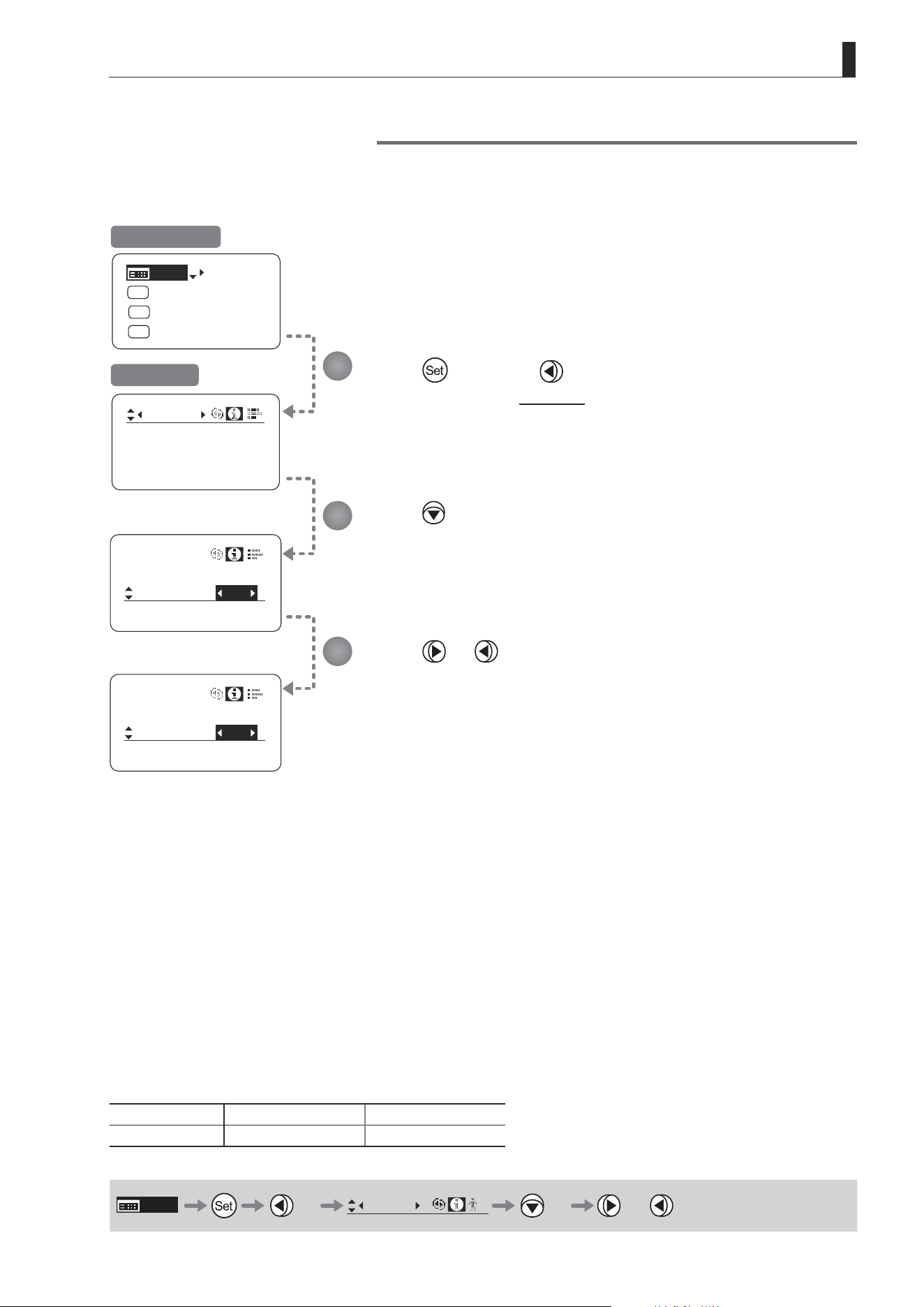
Specifying Analog Demand Responsiveness
Congure the responsiveness of zoom speed adjustment in response to pressing the analog demand thumb ring.
(Note: Another screen is displayed when this setting is congured.)
Press once and four times.
The display switches to the Zoom screen.
Press or .
Press left or right until you reach
the desired function.
Press .
[CurveMode] is underlined.
Press twice.
[Demand] is underlined.
The previous or default value is
highlighted.
Press .
The display switches to the CurveMode screen.
Press .
The display reverts to Screen A.
Initial Top Screen
Zoom Screen
Screen A
CurveMode Screen
Options 1 2 3 4
(D)
5 6 7 8 9
(D): Default value
MENU
× 4
Zoom
[ ]
× 2 or
1
2
3
4
5
6
(1)
(9)
Responsiveness to
zoom mode adjustment
Maximum
Zoom Speed
Wide Angle Telephoto
Extent of tilting the analog demand
Zoom Direction
E58
3. Operation in Basic Mode
CurveMode
VR-Dem: ON
Zoom
[]
CurveMode
CurveMode
VR-Dem:
Zoom
[]
ON
VR-Dem:
Zoom
[]
OFF
[Trk]
OFF
Shtl
A 1
A 2
MENU
IG: 50
A
Fr1P
Fr1P
[I-Tq]H
[Adj]
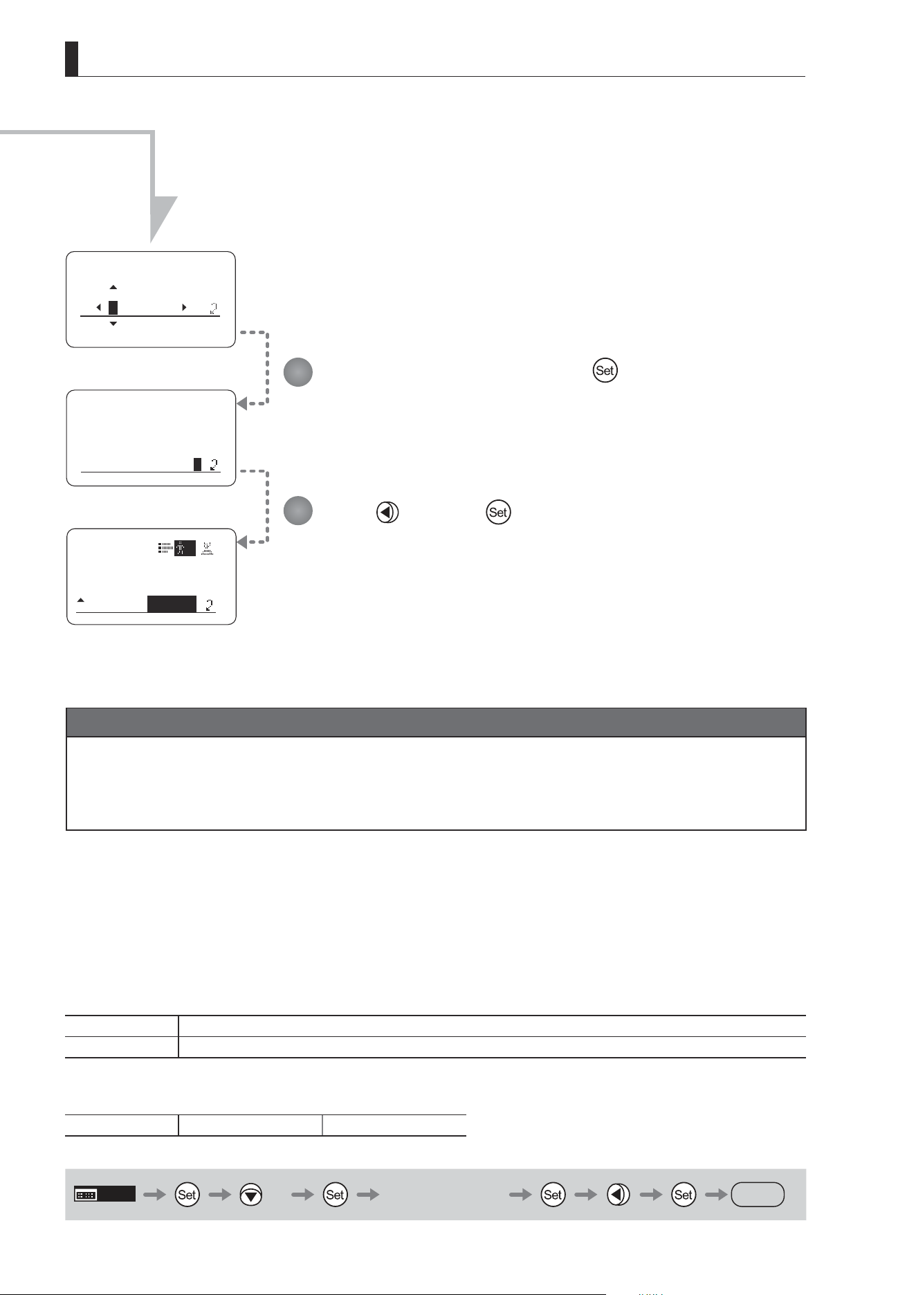
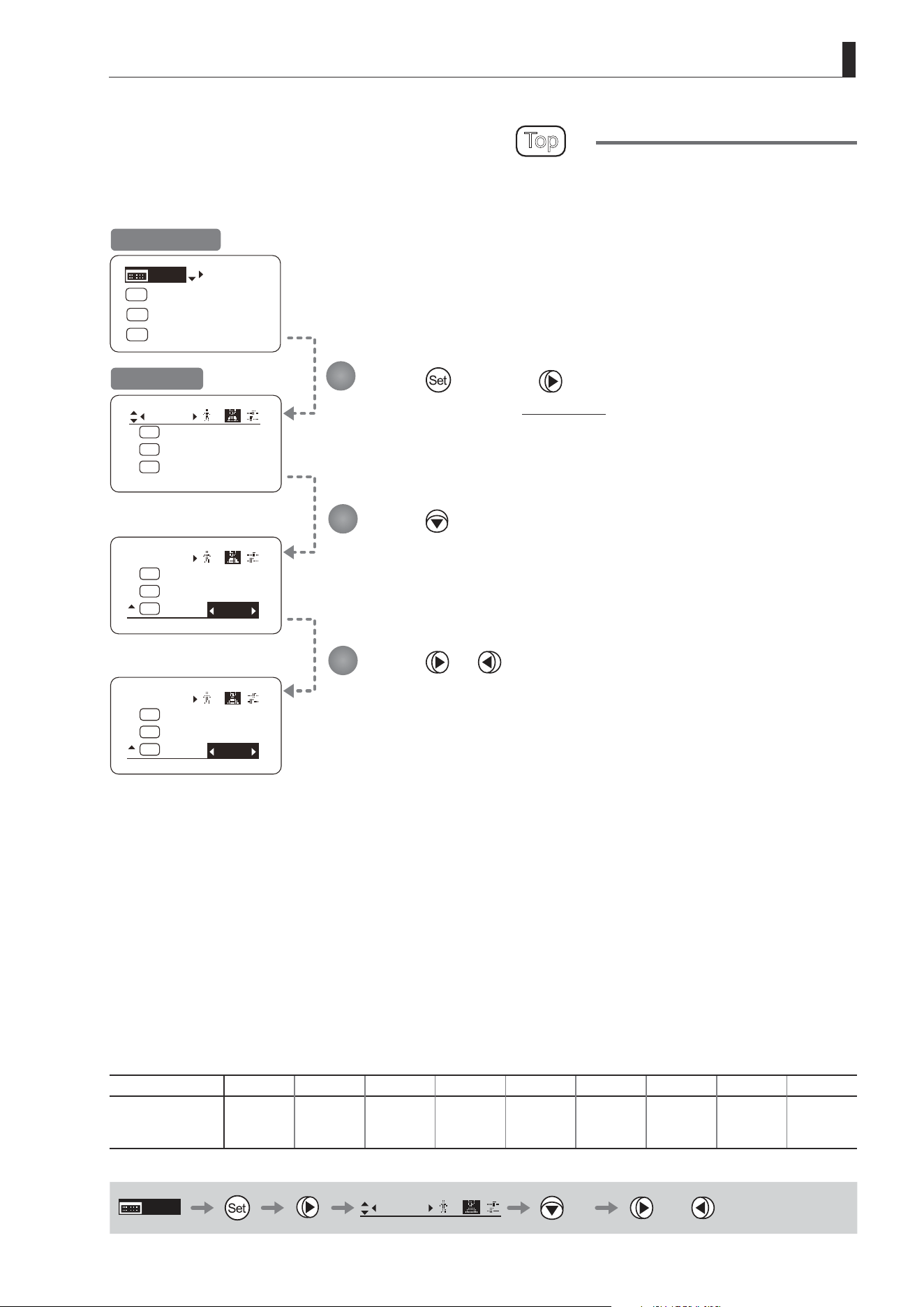
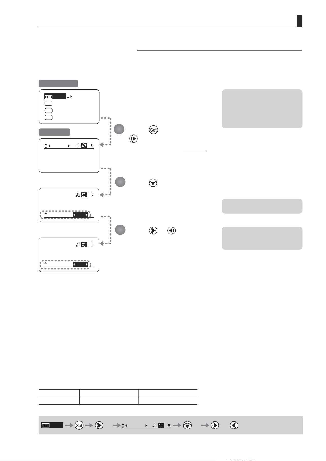
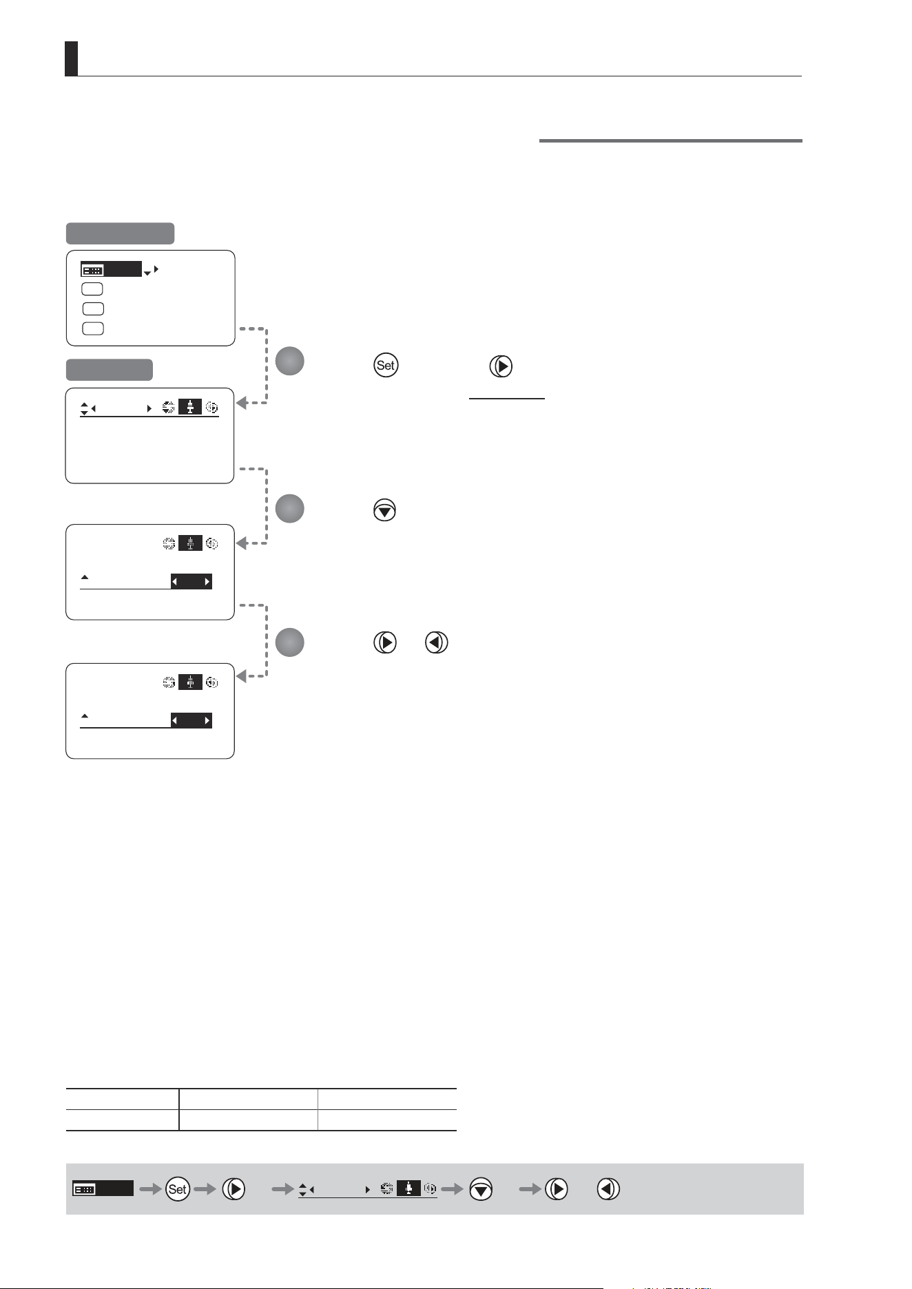
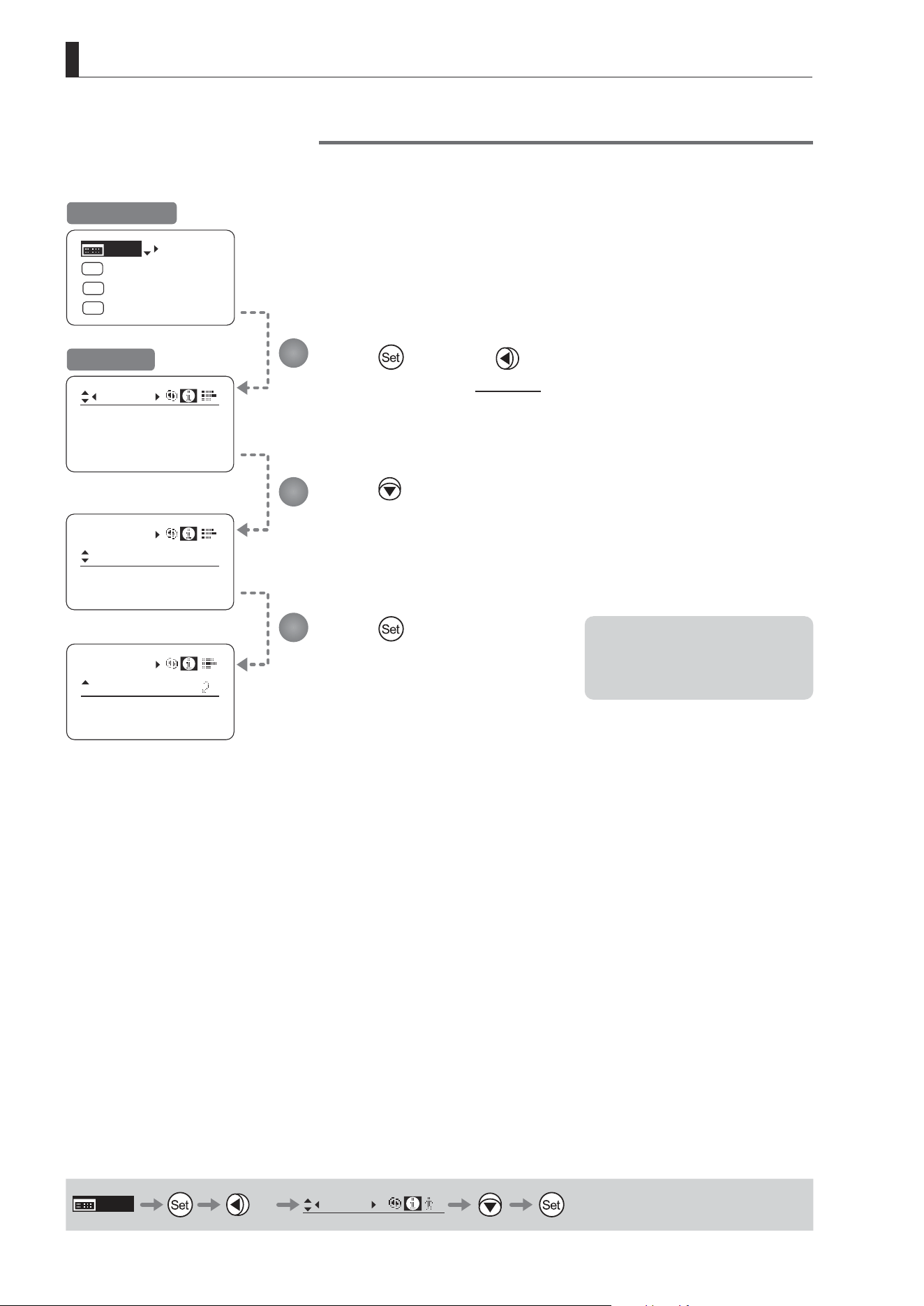
Demand-Based Zoom Speed Adjustment ON/OFF
Enable or disable adjustment of the maximum drive unit zoom speed based on the zoom demand.
Press once and four times.
The display switches to the Zoom screen.
Press twice.
[VR-Dem] is underlined.
The previous or default function is highlighted.
Press or .
Press left or right to switch the function {ON} or {OFF}.
Initial Top Screen
Zoom Screen
Options
(D)
ON OFF
Description Enabled Disabled
(D): Default value
MENU
× 4
Zoom
[ ]
× 2 or
1
2
3

E59
3. Operation in Basic Mode
3.2.6 Focus Screen Settings
The following setting items can be congured on the Focus screen.
Specifying Focus Demand Responsiveness
E60
3. Operation in Basic Mode
Focus
[]
CurveMode
ADemand: 5
Focus
[]
CurveMode
CurveMode
ADemand:
D5
Focus
[]
CurveMode
ADemand: 7
Focus
[]
CurveMode
Focus
[]
[ I-Gain ]
[Adj]
[]
MENU
1
A
Fr1P
[ Basic ]
[Trk]
OFF
[I-Tq]H
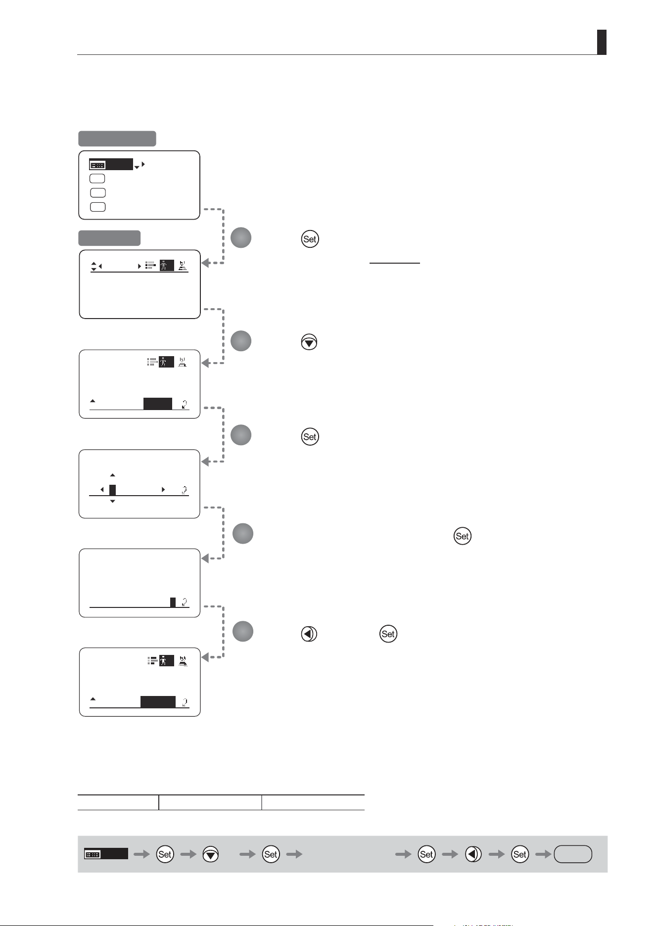
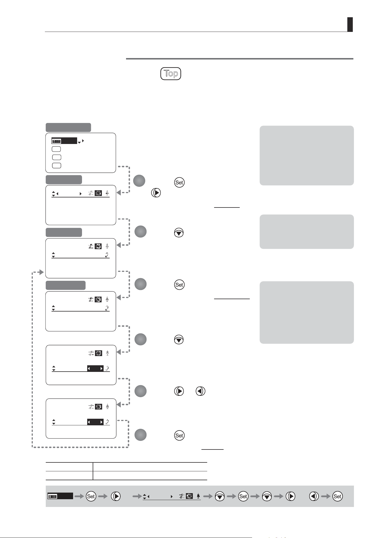
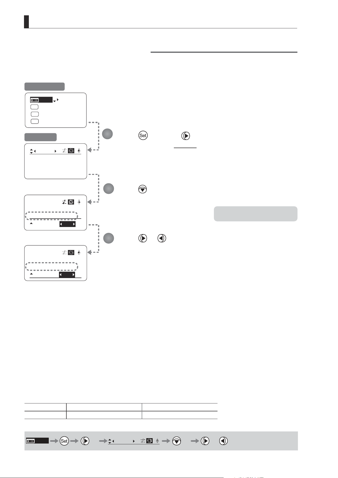
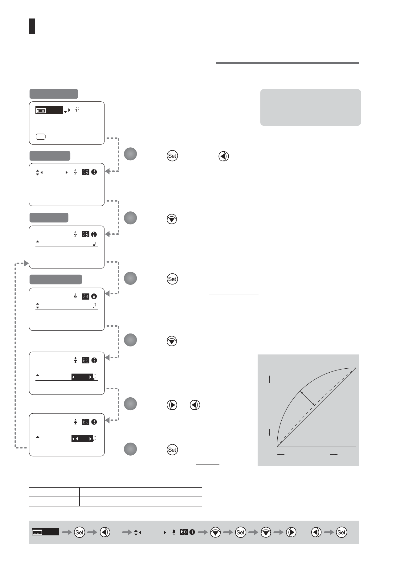
Specifying Focus Demand Responsiveness
Specify responsiveness in analog focus demand operations as needed.
Press once and three times.
The display switches to the Focus screen.
Press or .
Press left or right until you reach the desired
function.
Press .
[CurveMode] is underlined.
Press .
[ADemand] is underlined.
The previous or default value is
highlighted.
Press .
The display switches to the CurveMode screen.
Press .
The display reverts to Screen A.
Initial Top Screen
Focus Screen
Screen A
CurveMode Screen
Options 1 to 9
Description Large curve Small curve
Default value: 5
MENU
× 3
Focus
[ ]
or
Note: These settings take eect
when the curve selection
switch on the focus demand is
set toward FAR.
Standard
1
9
Innity
Close
Range
Focus Position
Knob Position
1
2
3
4
5
6

E61
3. Operation in Basic Mode
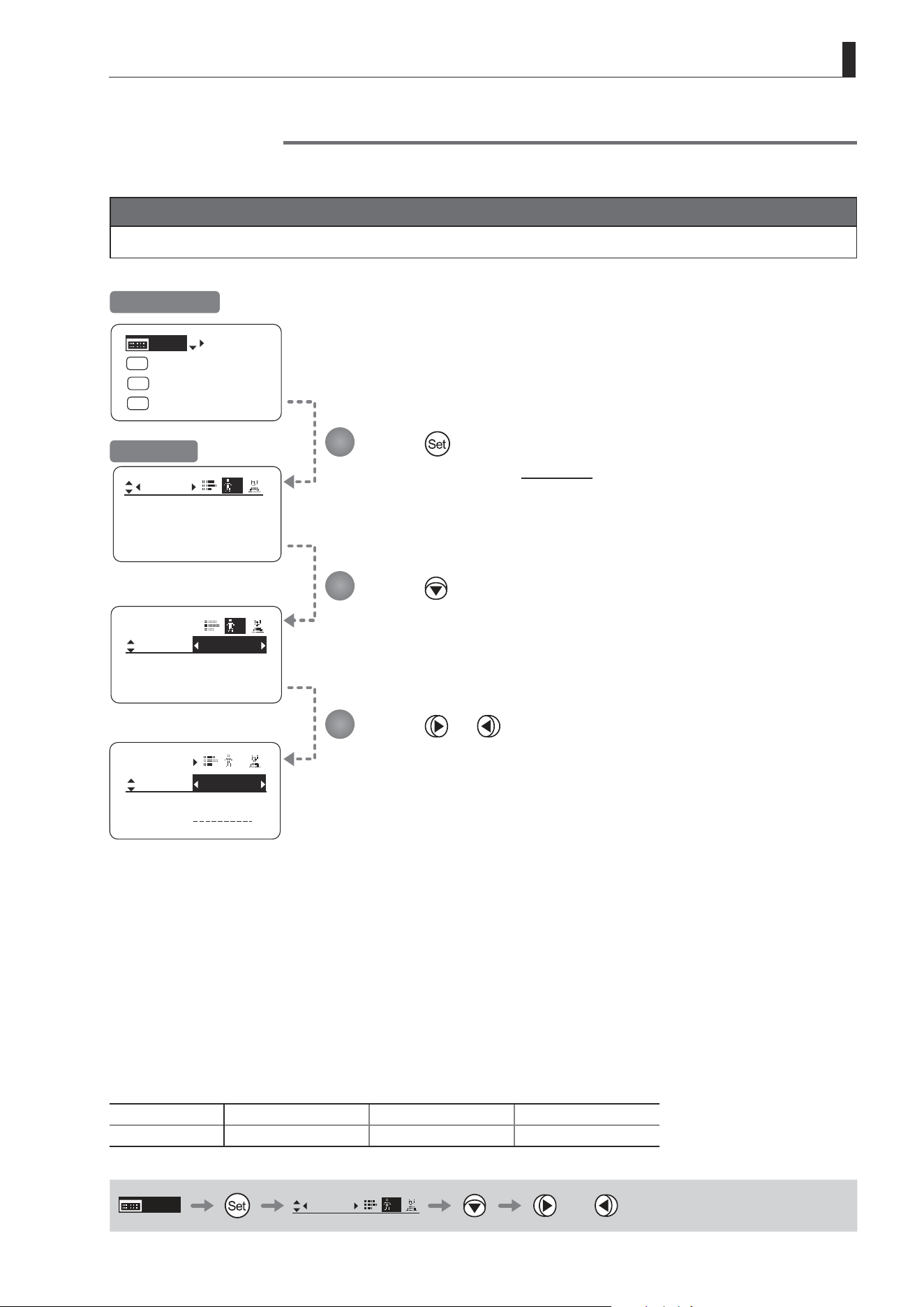
3.2.7 Info Screen Settings
The following setting items can be congured on the Info screen.
Checking Serial Numbers
Specifying the 3D Function (For information on specifying the 3D function, see the instruction manual of the BC-100 3D
cable.)
Specifying Encoder Output
Serial Communication with Camera ON/OFF
Specifying the Input Route for Command Signals from the Camera
Specifying the
Technology Distance Unit
Checking Lens–Drive Unit Communication
E62
3. Operation in Basic Mode
[Trk]
OFF
Shtl
A 1
A 2
MENU
IG: 50
A
Fr1P
Fr1P
[I-Tq]H
[Adj]
Info
Encoder:
OFF
S/N
Info
Encoder:
OFF
S/N
Info
D.U.:
00000000
Lens:
00000000
S/N
3D:
3D:
OFF
OFF
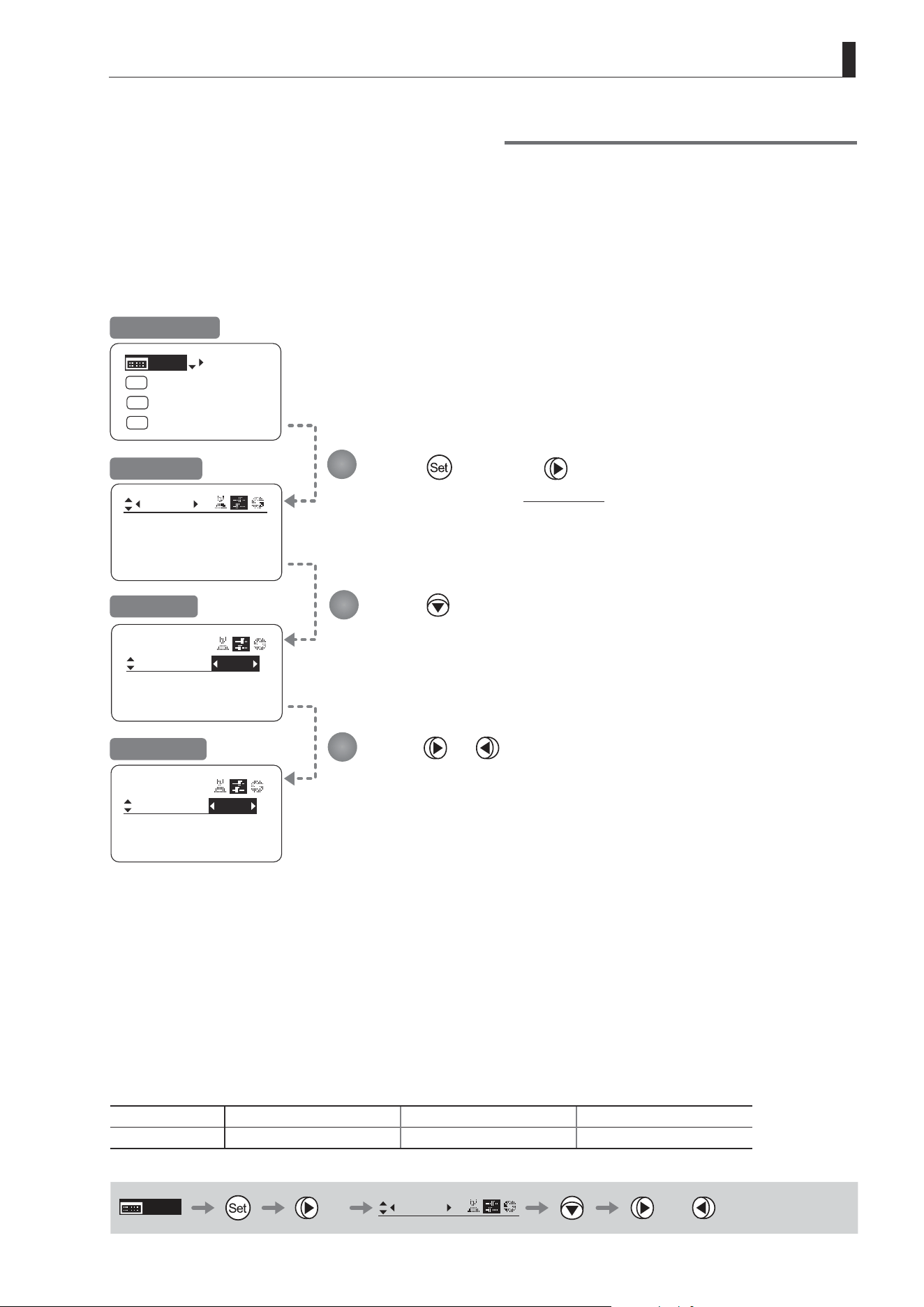
Checking Serial Numbers
Check lens and drive unit serial numbers as needed.
Press once and twice.
The display switches to the Info screen.
Press .
[S/N] is underlined.
Press .
The lens and drive unit serial numbers are
displayed.
Initial Top Screen
Info Screen
MENU
× 2
Info
B
1
2
3
Note: The serial number of the lens
is not displayed when no
power is being supplied to the
lens from the camera mount.
E63
3. Operation in Basic Mode
Encoder:
INDOFF
Info
CamSeri:
ON
[Trk]
OFF
Shtl
A 1
A 2
MENU
IG: 50
A
Fr1P
Fr1P
[I-Tq]H
[Adj]
Info
Encoder:
OFF
3D:
Encoder:
IND
ON
Info
CamSeri:
ON
OFF
3D:
OFF
3D:
OFF
S/N
Specifying Encoder Output
Enable or disable encoder output as needed. Enabling output enables virtual connector output. For details, contact
Canon or your dealer.
Press once and twice.
The display switches to the Info screen.
Press three times.
[Encoder] is underlined.
Press or .
Press left or right to switch the function {ON} or {OFF}.
Initial Top Screen
Info Screen
Options
(D)
OFF ON
Description Output disabled Output enabled
(D): Default value
MENU
× 2
Info
B
× 3 or
1
2
3
E64
3. Operation in Basic Mode
Info
OFF
CamSeri:
Encoder :
OFF
[Trk]
OFF
Shtl
A 1
A 2
MENU
IG: 50
A
Fr1P
Fr1P
[I-Tq]H
[Adj]
Info
Encoder:
S/N
Encoder:
IND
ON
Info
CamSeri:
OFF
I/Fprior
Cable
I/Fprior
Cable
OFF
3D:
OFF
Serial Communication with Camera ON/OFF
Two types of camera–lens interfaces are available: analog control or control via serial communication. This setting
enables you to switch between auto control detection and analog control.
By default, this setting is ON, enabling auto detection of whether serial or analog control is used.
To restrict the interface to analog control, set it to OFF.
Press once and twice.
The display switches to the Info screen.
Press four times.
[CamSeri] is underlined.
Press or .
Press left or right to switch the function {ON} or {OFF}.
Initial Top Screen
Info Screen
Options
(D)
ON OFF
Description
Serial communication with the camera
Enabled
Serial communication with the camera
Disabled
(D): Default value
MENU
× 2
Info
× 4 or
1
2
3
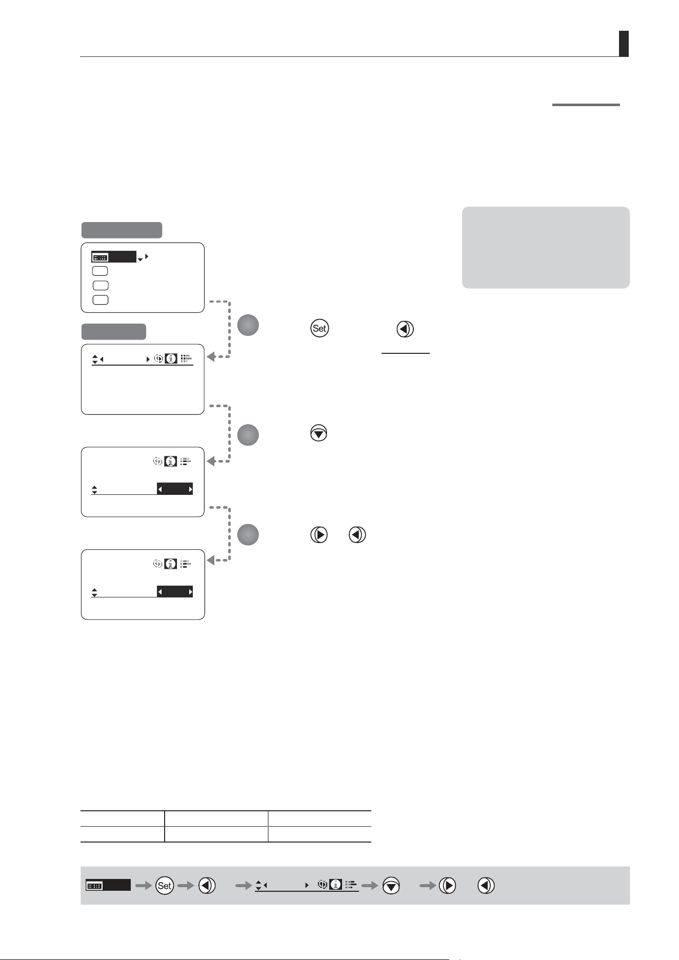
E65
3. Operation in Basic Mode
[Trk]
OFF
Shtl
A 1
A 2
MENU
IG: 50
A
Fr1P
Fr1P
[I-Tq]H
[Adj]
Info
Encoder: OFF
S/N
IND
ON
Info
CamSeri:
I/Fprior
Cable
/ i
IND
ON
Info
CamSeri:
I/Fprior
Mount
/ i
3D:
OFF
Specifying the Input Route for Command Signals from the Camera
There are two input routes for command signals from the camera: via the mount and via the 12-pin cable. This setting
species the input route for command signals from the camera. The default setting is “Mount,” and in this case command
signals received via the mount are given priority.
However, the command signals via the 12-pin cable are received automatically if no command signals are input via the
mount. When the “Cable” setting is selected, only command signals received via the 12-pin cable are used.
Press once and twice.
The display switches to the Info screen.
Press ve times.
[I/Fprior] is underlined.
Press or .
Press left or right to switch the function {Cable} or {Mount}.
Initial Top Screen
Info Screen
Options
(D)
Mount Cable
Description Via mount Via 12-pin cable
(D): Default value
MENU
× 2
Info
× 5 or
1
2
3
Note: Set {Mount} when using the
auto focus function of the
camera. (For the camera models
that support the auto focus
function, contact your Canon
dealer.)
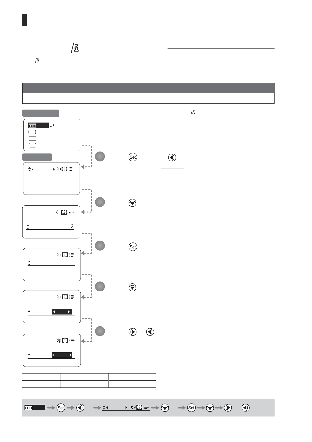
E66
3. Operation in Basic Mode
State:
Info
I/Fprior
Mount
/ i
/ i
Units: Feet
Info
[Trk]
OFF
Shtl
A 1
A 2
MENU
IG: 50
A
Fr1P
Fr1P
[I-Tq]H
[Adj]
Info
OFF
Encoder:
OFF
S/N
/ i
Units:
Feet
Info
/ i
Units:
Meters
Info
3D:
Specifying the Technology Distance Unit
When
Technology is used (only when a PL mount camera is attached), it is possible to specify the initial setting for the unit (feet
or meters) used to express distances in information sent to the camera. Accordingly, information sent for the actual subject distance,
hyperfocal distance, subject distance at close range and innity, and entrance pupil position is expressed in the specied unit.
Note
Any distance unit set on the camera takes precedence.
Press once and twice.
The display switches to the Info screen.
Press six times.
[/ i] is underlined.
Press .
Press
.
[Units] is underlined.
The previous or default value is highlighted.
Press or .
Press left or right to switch the function {Feet} or {Meters}.
Options
(D)
Feet Meters
Description Expressed in feet Expressed in meters
(D): Default value
MENU
× 2
Info
× 6 or
1
2
3
4
5
Initial Top Screen
Info Screen
is trademark of Cooke Optics Limited.
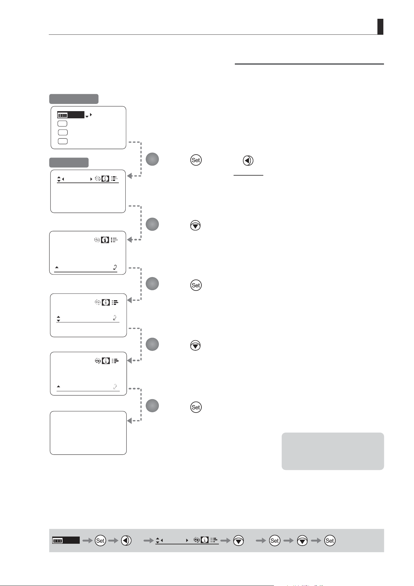
E67
3. Operation in Basic Mode
State
Info
I/Fprior
Mount
/ i
Lens
State
Info
[Trk]
OFF
Shtl
A 1
A 2
MENU
IG: 50
A
Fr1P
Fr1P
[I-Tq]H
[Adj]
Info
Encoder:
OFF
S/N
Meter
Lens
State
Info
Lens Interface:
Connected
OFF
3D
:
Checking Lens–Drive Unit Communication
View the status of communication between the lens and drive unit as follows.
Press once and twice.
The display switches to the Info screen.
Press seven times.
[State] is underlined.
Press .
Press
.
[Lens] is underlined.
Press .
This screen indicates normal
communication.
If “Non-connected” is displayed, contact
Canon or your dealer.
MENU
× 2
Info
× 7
1
2
3
4
5
Initial Top Screen
Info Screen
Note: “Non-connected” is displayed
when no power is being
supplied to the lens from the
camera mount.

E68
3. Operation in Basic Mode
3.2.8 Fol. Screen Settings
The following setting items can be congured on the Fol. screen.
Viewing Lens Follow Settings (Iris, Zoom, Focus)
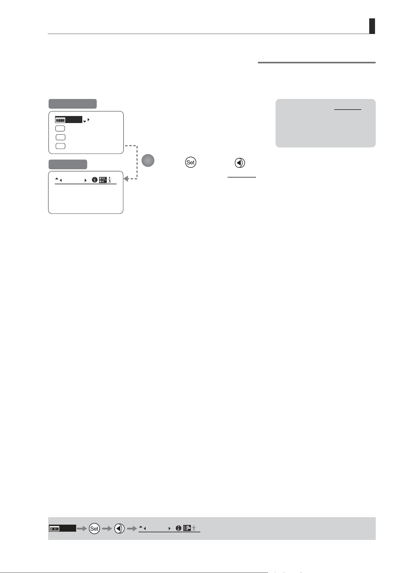
E69
3. Operation in Basic Mode
Fol.
Iris:
Zoom:
Focus:
0000
1000
0000
B
[Trk]
OFF
Shtl
A 1
A 2
MENU
IG: 50
A
Fr1P
Fr1P
[I-Tq]H
[Adj]
Viewing Lens Follow Settings (Iris, Zoom, Focus)
Indicates values in the full range of mechanical iris, zoom, and focus operations, expressed as relative values in the
range of 0–1000.
Press and then .
The display switches to the Fol. screen, showing relative follow iris, zoom, and focus
values.
Initial Top Screen
Fol. Screen
MENU
Fol.
B
Note: As long as the Fol. screen
is shown, the display will not
turn o automatically after
2 minutes if left idle.
To turn o the display, press
the Display switch.
1
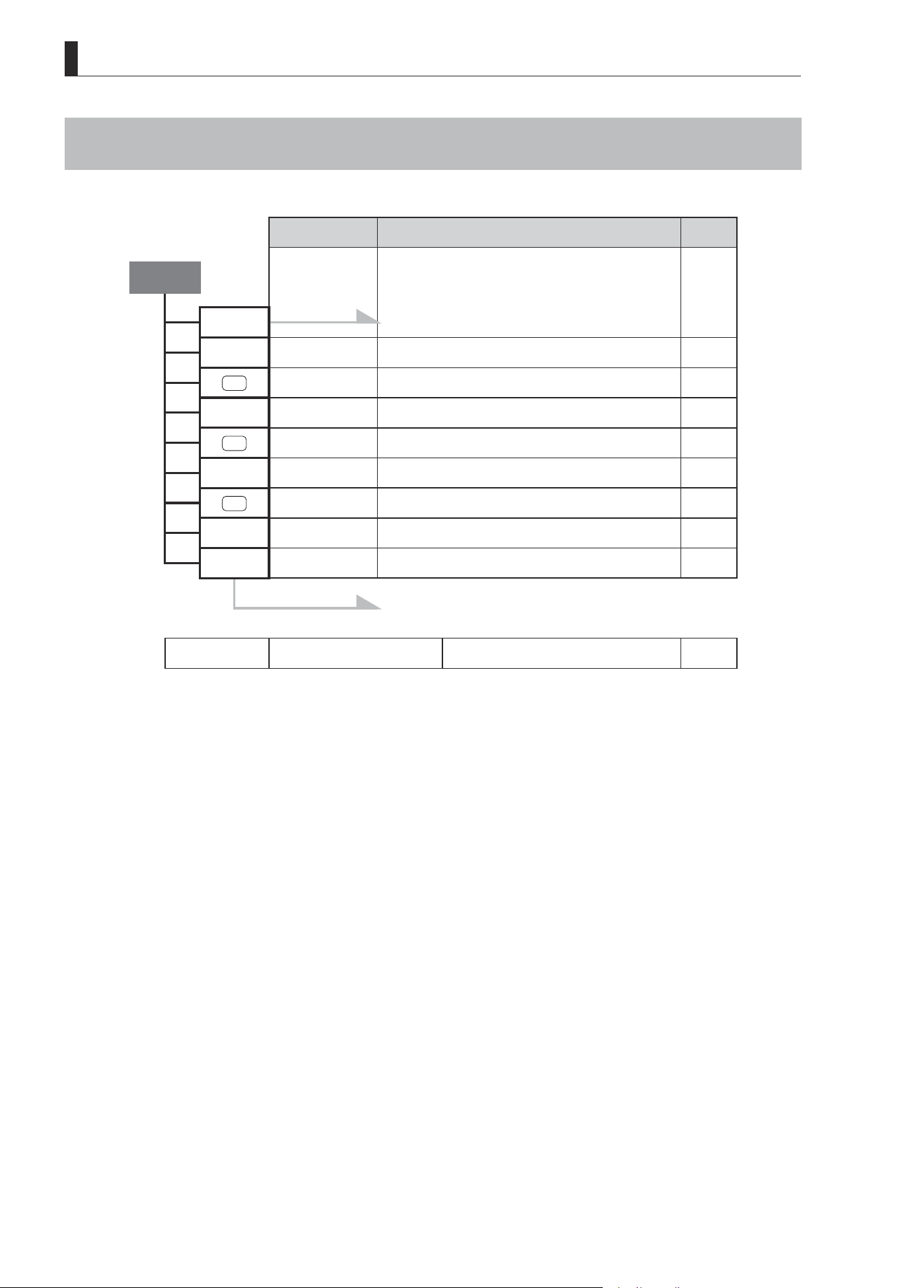
E70
3. Operation in Basic Mode
3.3 List of Settings
Default Value Options Page
Top
MENU To *1 on the next page
IG 50 01–99
A
Fr1P VTR / RET / Fr1P / Fr1F / Fr2P / Fr2F / Sped / Shtl / NON
[Adj] n y / n
A 1
Shtl VTR / RET / Fr1P/ Fr1F / Fr2P / Fr2F / Sped / Shtl / NON
[Trk] OFF OFF / ON
A 2
Fr1P VTR / RET / Fr1P / Fr1F / Fr2P / Fr2F / Sped / Shtl / NON
[I-Tq] H H / L
[Z.M.]
To *2 on the next page
Escape Operation Jump to user 0 setting status
Hold down both the Display switch and Set key
for at least 2 seconds.
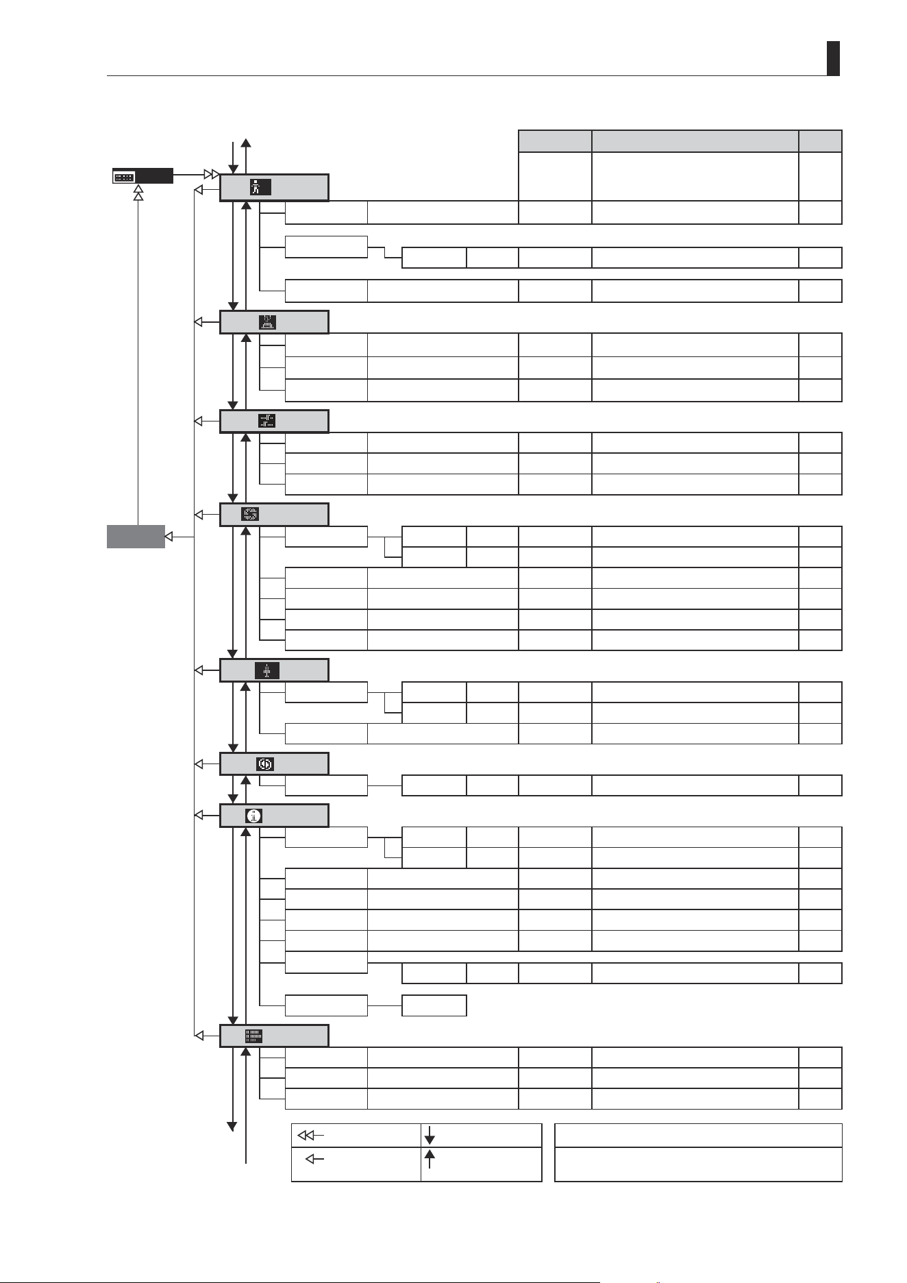
E71
3. Operation in Basic Mode
Default Value
Options Page
MENU
User
*
*1
Mode
Basic Basic / Analog / Full
ResetAll
User n y / n
Access Unlock Unlock / Lock
Switch
AUX
Fr1P
VTR / RET / Fr1P / Fr1F / Fr2P / Fr2F /
Sped / Shtl / NON
AUX1 Shtl
VTR / RET / Fr1P / Fr1F / Fr2P / Fr2F /
Sped / Shtl / NON
AUX2 Fr1P
VTR / RET / Fr1P / Fr1F / Fr2P / Fr2F /
Sped / Shtl / NON
Preset
Frame1
Zoom Zoom / Focus / Z+F
Frame2 Zoom Zoom / Focus / Z+F
ZSpeed 800 1–800
Iris
Go Top
[I-Gain]
Auto 50 01–99
Remote 90 01–99
Torque High High / Low
Comp ON ON / OFF
Close OFF OFF / ON
Controller OFF OFF / ON
Zoom
[ ]
CurveMode
Seesaw 5 1–9
*2
Demand 5 1–9
VR-Dem ON ON / OFF
Focus
CurveMode
ADemand 5 1–9
Info
S/N
Lens 8-digit serial number
D.U. 8-digit serial number
3D
#1
OFF OFF / ON
Encoder OFF OFF / ON
CamSeri ON OFF / ON
I/Fprior Mount Mount / Cable
/i
Unit Feet Feet / Meters
State Lens
Fol.
*3
Iris
(**) (0000–1000)
Zoom (**) (0000–1000)
Focus (**) (0000–1000)
To *1
From *1
: Set key operation : Right key operation ( ) : Indicates values that cannot be changed.
: Up key operation : Left key operation #1 : For information on specifying the 3D communication,
see the “3D Cable Instruction Manual.”
From *3 To *3

Memo

Operation in Full Mode
4
INFORMATION DISPLAY
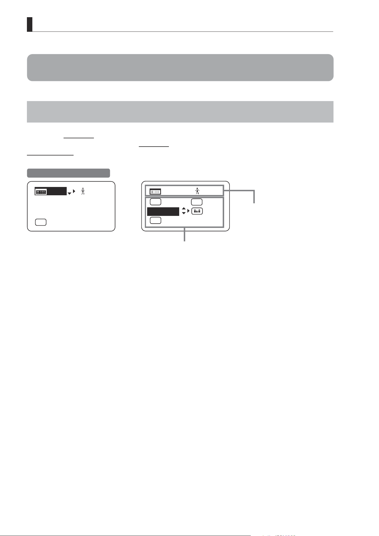
E74
4. Operation in Full Mode
4. Operation in Full Mode
4.1 Conguration from the Top Screen
To access the Top screen, press the Display switch.
A total of 15 items can be congured on the Top screen in Full mode. The rst screen displayed is referred to as the
Initial Top screen. Status of some items can be checked simply by accessing this screen.
Items not scrolled
Items displayed by scrolling
[]
MENU
1
Norm
AM
Zoom
RET
R
A 2
Fr1P
[ Z.M. ]
Initial Top Screen in Full Mode
[ I-Gain ]
[Adj]
[]
MENU
1
A
Fr1P
[ Basic ]
[Trk]
OFF
[I-Tq]H
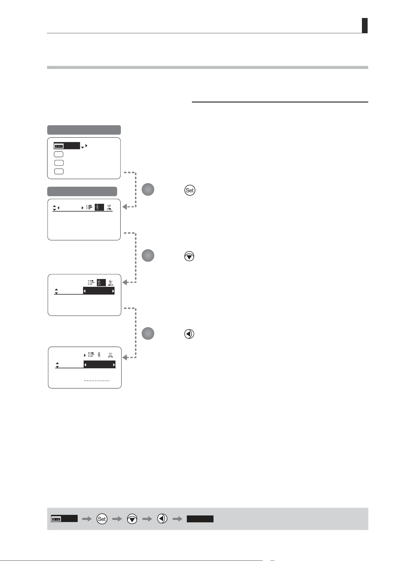
E75
4. Operation in Full Mode
Mode:
User
Basic
Access:
ResetAll
B
Unlock
Mode:
User
Basic
Access:
ResetAll
B
Unlock
No. :
User
1
Name:
Mode:
1
Full
[Trk]
OFF
Shtl
A 1
A 2
MENU
IG: 50
A
Fr1P
Fr1P
[I-Tq]H
[Adj]
4.1.1 Selecting Full Mode
Basic mode is the default mode, but Full mode can be accessed as follows.
Switching from Basic to Full Mode
Initial Top Screen in Basic Mode
User Screen in Basic Mode
MENU
[ Full ]
Press .
Press
.
[Basic] is highlighted.
Press .
[Full] is now highlighted, indicating conrmation.
1
2
3
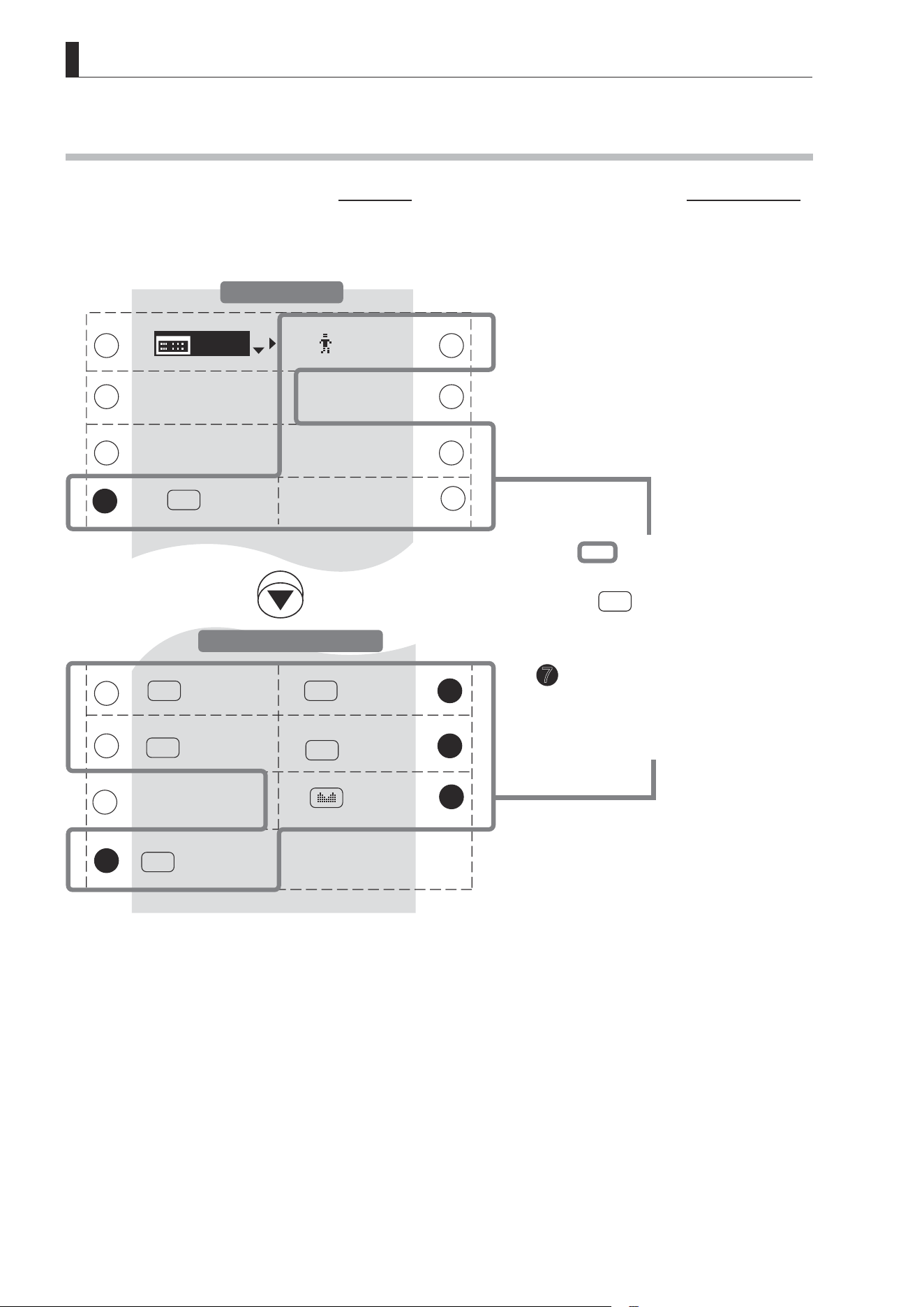
E76
4. Operation in Full Mode
[ I-Gain ]
[Trk]
OFF
Shtl
VTR
A 1
Fr1P
A
V
RET
R
[]
MENU
1
[ I-Tq ] H
[ Z.M. ]
Zoom
Norm
AM
9
11
15
15
14
14
[ Basic ]
Fr1P
A 2
[ Adj ]
13
1
3
7
7
10
10
4
2
5 6
8
12
12
4.1.2 Top Screen
A total of 15 items can be congured on the Top screen in Full mode, and 8 items are shown on the Initial Top screen.
The other 7 can be accessed by pressing down to scroll down the screen.
(See the following gure.)
Status of some items can be checked simply by accessing this screen. (Shown in the gure below.
*1
)
*1
Inside
: Items that show the current
setting status.
Example:
Shtl
A 1
indicates that the
AUX1 switch is assigned to the
Shuttle function.
7
: White numbers against a black
background indicate the number of
the switch on a drive unit to which the
function is assigned.
Items Displayed by Scrolling
Initial Top Screen
E77
4. Operation in Full Mode
1
MENU
Menu screen
See “4.2 Conguration from the Menu Screen.”
9
A 1
AUX1 switch
By default, the AUX1 switch for a zoom
demand is assigned to the {Shuttle} function,
but it can be reassigned as needed.
See “4.1.10 Assigning Functions to the AUX1
Switch.”
1 2
[ ]
User
Adjust settings for up to ten users (0–9), to
distinguish settings by user. Switch users from
this screen, either to use or change the settings.
See “4.1.3 Switching Users.”
9
10
V
VTR switch
By default, the VTR switch for a drive unit is
assigned to the {VTR} function, but it can be
reassigned as needed.
See “4.1.11 Assigning Functions to the VTR Switch.”
3
[Basic]
Switching to Basic Mode
Switch to Basic mode as needed.
See “4.1.4 Switching to Basic Mode.”
11
A 2
AUX2 switch
By default, the AUX2 switch for a zoom
demand is assigned to the {Frame Preset 1}
function, but it can be reassigned as needed.
See “4.1.12 Assigning Functions to the AUX2 Switch.”
3 4
[Adj]
Mechanical end auto-adjustment
Perform automatic adjustment of the
mechanical end in zoom, focus, and iris
operations on the lens and drive unit.
See “4.1.5 Auto-Adjusting the Mechanical End.”
12
R
RET switch
By default, the RET switch for a drive unit is
assigned to the {Return} function, but it can be
reassigned as needed.
See “4.1.13 Assigning Functions to the RET Switch.”
5
[I-Gain]
Iris gain
Adjust the auto iris gain or the remote iris gain
value as needed.
See “4.1.6 Specifying Iris Gain.”
13
[Z.M.]
Zoom curve mode
Adjust zoom speed in response to pressing the zoom
seesaw switch or tilting the analog demand thumb ring.
See “4.1.14 Specifying Zoom Curve Mode.”
5
6
[Trk]
Zoom tracking
Switch to ON when using zoom tracking.
See “4.1.7 Zoom Tracking ON/OFF.”
14
Seesaw
Enable iris control using the zoom seesaw
switch.
See “4.1.15 Assigning Functions to the
Seesaw.”
7
A
AUX switch
By default, the AUX switch for a drive unit is
assigned to the “Frame Preset 1” function, but
it can be reassigned as needed.
See “4.1.8 Assigning Functions to the AUX Switch.”
15
AM
Iris A/M switch
Adjust movement of the iris A/M switch on the
drive unit.
See “4.1.16 Specifying Iris A/M Switch.”
8
7
[I-Tq]
Iris torque
Adjust the level of torque in manual control of
the iris ring as needed.
See “4.1.9 Specifying Iris Torque.”
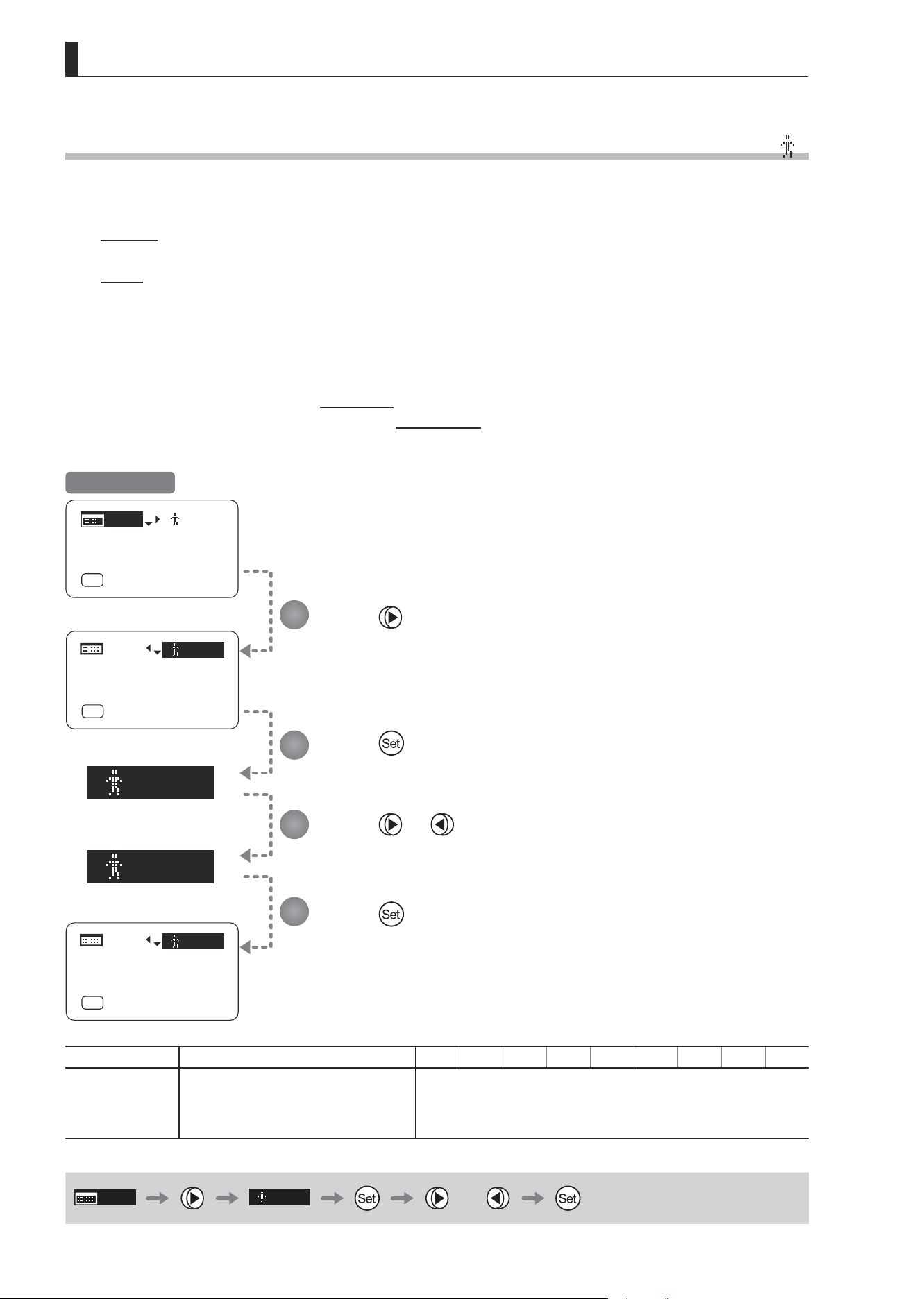
E78
4. Operation in Full Mode
[]
1
[]
2
[]
1
MENU
MENU
MENU
[ I-Gain ]
[Adj]
[]
MENU
1
A
Fr1P
[ Basic ]
[Trk]
OFF
[I-Tq]H
[ I-Gain ]
[Adj]
A
Fr1P
[ Basic ]
[Trk]
OFF
[I-Tq]H
[]
2
MENU
MENU
MENU
[ I-Gain ]
[Adj]
A
Fr1P
[ Basic ]
[Trk]
OFF
[I-Tq]H
4.1.3 Switching Users [
]
Settings for users 0–9 can be congured in Full mode.
User 1–9
Congure advanced settings for each user needed. Settings for the users can then be saved.
User 0
User 0 is the default user. Thus, for this user you can adjust settings temporarily but not save them.
Setting information is cleared when you switch to users 1–9 or turn the lens o. User 0 is used if you perform an
escape operation. For details, see “4.1.17 Escape Operation.” Selecting user 0 restores the default settings, except
for the auto and remote iris gain values and encoder output setting.
Switch to the desired user (0–9) from the Top screen.
Congure advanced settings for these users from the Menu screen. See “4.2 Conguration from the Menu Screen.”
Press .
The previous or default value is highlighted.
Press .
The display starts blinking.
Press or .
Press left or right until you reach the desired value.
Press .
The display changes from blinking to highlighted, indicating conrmation.
1
2
3
4
Initial Top Screen
Options 0
(D)
1 2 3 4 5 6 7 8 9
Save Settings
Not supported
Although settings cannot be saved, they can be
changed temporarily.
Switching users or turning the lens o will restore
default values.
Can be saved for each user
(D): Default value
MENU
[ ]
1
or
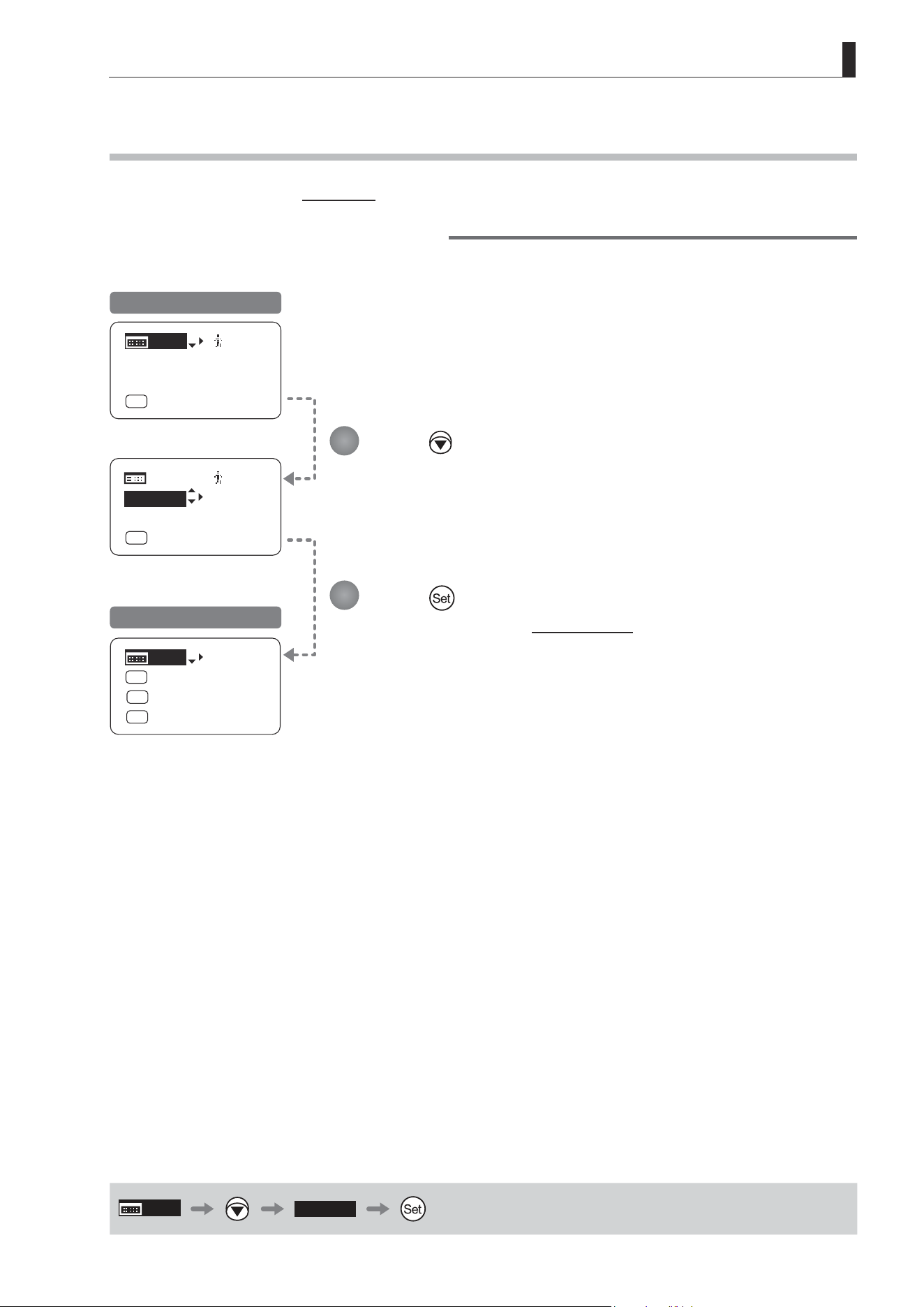
E79
4. Operation in Full Mode
MENU
MENU
[ Basic ]
[ I-Gain ]
[Adj]
[]
MENU
1
A
Fr1P
[ Basic ]
[Trk]
OFF
[I-Tq]H
[ I-Gain ]
[Adj]
[]
1
A
Fr1P
[Trk]
OFF
[I-Tq]H
[Trk]
OFF
Shtl
A 1
A 2
MENU
IG: 50
A
Fr1P
Fr1P
[I-Tq]H
[Adj]
4.1.4 Switching to Basic Mode [Basic]
Switch to Basic mode from the Top screen as needed.
Switching from Full to Basic Mode
Initial Top Screen in Full Mode
Initial Top Screen in Basic Mode
Press .
[Basic] is highlighted.
Press .
The mode switches, and the Initial Top screen in Basic mode is displayed.
1
2
MENU
[ Basic ]
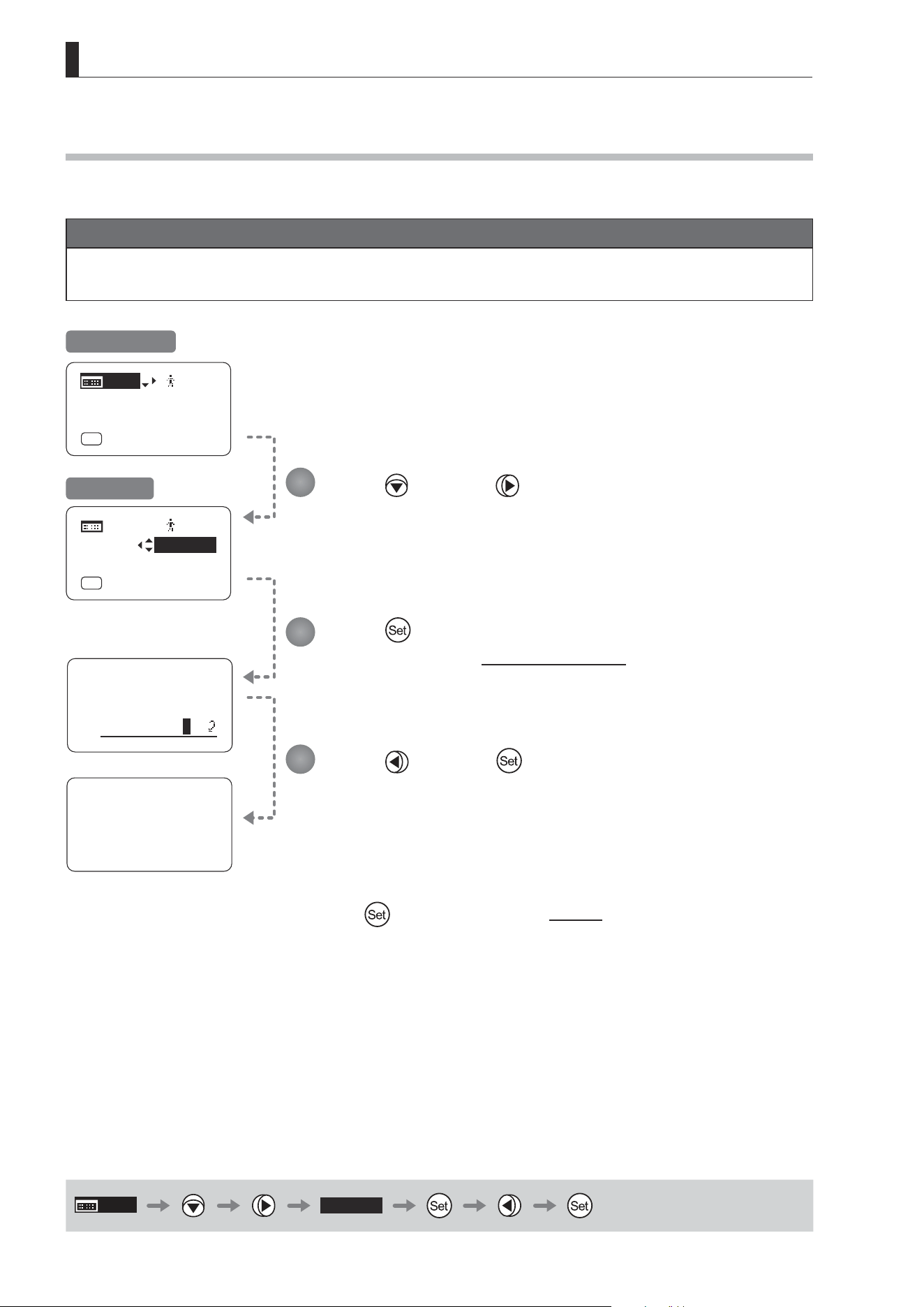
E80
4. Operation in Full Mode
4.1.5 Auto-Adjusting the Mechanical End [Adj]
Perform automatic adjustment of the mechanical end in zoom, focus, and iris operations on the lens and drive unit.
Note
If “Auto-Adjustment: Error/Lens Interface: Non-Connected” is displayed after adjustment, contact Canon or your
dealer.
MENU
[Adj]
Lens
AutoAdjust
OK?
y/n
Auto-Adjustment:
Succeeded
Lens Interface:
Connected
[ I-Gain ]
[Adj]
[]
MENU
1
A
Fr1P
[ Basic ]
[Trk]
OFF
[I-Tq]H
[ I-Gain ]
[]
1
A
Fr1P
[ Basic ]
[Trk]
OFF
[I-Tq]H
Initial Top Screen
Screen A
MENU
[Adj]
Press and then .
Your selection is now highlighted.
Press .
The display switches to the Auto-Adjustment screen.
Press and then .
Adjustment now begins.
During adjustment, the screen blinks.
After this, adjustment is nished.
Press
after adjustment to return to Screen A.
1
2
3
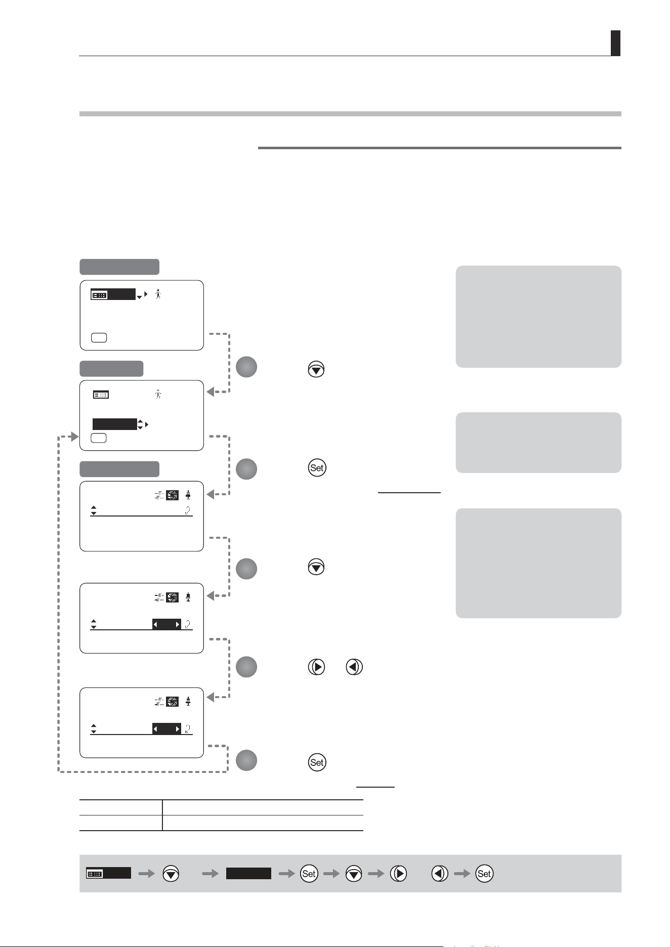
E81
4. Operation in Full Mode
[ I-Gain ]
[Adj]
[]
MENU
1
A
Fr1P
[ Basic ]
[Trk]
OFF
[I-Tq]H
[ I-Gain ]
Iris
Remote:
90
Auto:
50
[]
[ I-Gain ]
Iris
Remote:
90
Auto:
50
[]
[ I-Gain ]
Iris
Remote:
90
Auto:
71
[]
[ I-Gain ]
MENU
MENU
[Adj]
[]
1
A
Fr1P
[ Basic ]
[Trk]
OFF
[I-Tq]H
4.1.6 Specifying Iris Gain [I-Gain]
Specifying Auto Iris Gain
Although this value is factory-set, it can be adjusted as needed.
To adjust the value, use either the auto iris gain adjustment trimmer (refer to the operation manual "Lens") or display
operations. Regardless of the method of adjustment used, the most recent setting takes precedence.
The same auto iris gain value applies to all users, regardless of the current user. Thus, there is no need to switch users
in advance. Unlike most other setting adjustments, any changes to this setting also apply to user 0.
Options 01 to 99
Description Minimum gain Maximum gain
Default: Varies depending on the factory-set value, but corresponds to the value determined with the iris gain adjustment trimmer.
MENU
× 2
[I-Gain]
or
Note: Do the following when
adjusting gain while checking
iris operation.
→ Conrm that the drive unit A/M
switch is set to [Auto] mode.
→ Set the camera iris mode to
[Auto].
Note: As you look at the lens iris
ring, set it to the position of
maximum gain at which “focus
hunting” does not occur.
Note: The current iris gain value
is retained even if you reset
other settings as described in
“4.2.1 Resetting Values.” For
this reason, you will no longer
be able to view the default
setting. If necessary, make
a note of the default setting
before adjusting this value.
1
2
3
4
5
Press twice.
Your selection is now highlighted.
Press .
The display switches to the [I-Gain] screen.
Press .
[Auto] is underlined.
The previous or default value is
highlighted.
Press or .
Press left or right until you reach the desired value.
Press .
The display reverts to Screen A.
Initial Top Screen
Screen A
[I-Gain] Screen
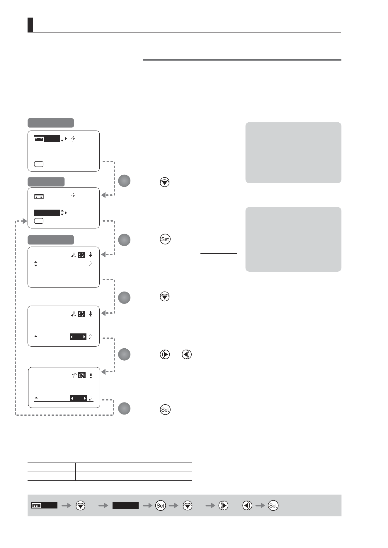
E82
4. Operation in Full Mode
[ I-Gain ]
Iris
Remote:
90
Auto:
50
[]
[ I-Gain ]
Iris
Remote:
50
Auto:
90
[]
[ I-Gain ]
Iris
Remote:
50
Auto:
80
[]
[ I-Gain ]
MENU
MENU
[ I-Gain ]
[Adj]
[]
MENU
1
A
Fr1P
[ Basic ]
[Trk]
OFF
[I-Tq]H
[Adj]
[]
1
A
Fr1P
[ Basic ]
[Trk]
OFF
[I-Tq]H
Specifying Remote Iris Gain
Although this value is factory-set, it can be adjusted as needed.
The same remote iris gain value applies to all users, regardless of the current user. Thus, there is no need to switch
users in advance. Unlike most other setting adjustments, any changes to this setting also apply to user 0.
Options 01 to 99
Description Minimum gain Maximum gain
Default value: 90
MENU
× 2
[I-Gain]
× 2 or
Note: Do the following when
adjusting gain while checking
iris operation.
→ Conrm that the drive unit A/M
switch is set to [Auto] mode.
→ Set the camera iris mode to
[Remote].
Note: The current iris gain value
is retained even if you reset
other settings as described in
“4.2.1 Resetting Values.” For
this reason, you will no longer
be able to view the default
setting. If necessary, make
a note of the default setting
before adjusting this value.
1
2
3
4
5
Press twice.
Your selection is now highlighted.
Press .
The display switches to the [I-Gain] screen.
Press twice.
[Remote] is underlined.
The previous or default value is highlighted.
Press or .
Press left or right until you reach the desired value.
Press .
The display reverts to Screen A.
Initial Top Screen
Screen A
[I-Gain] Screen
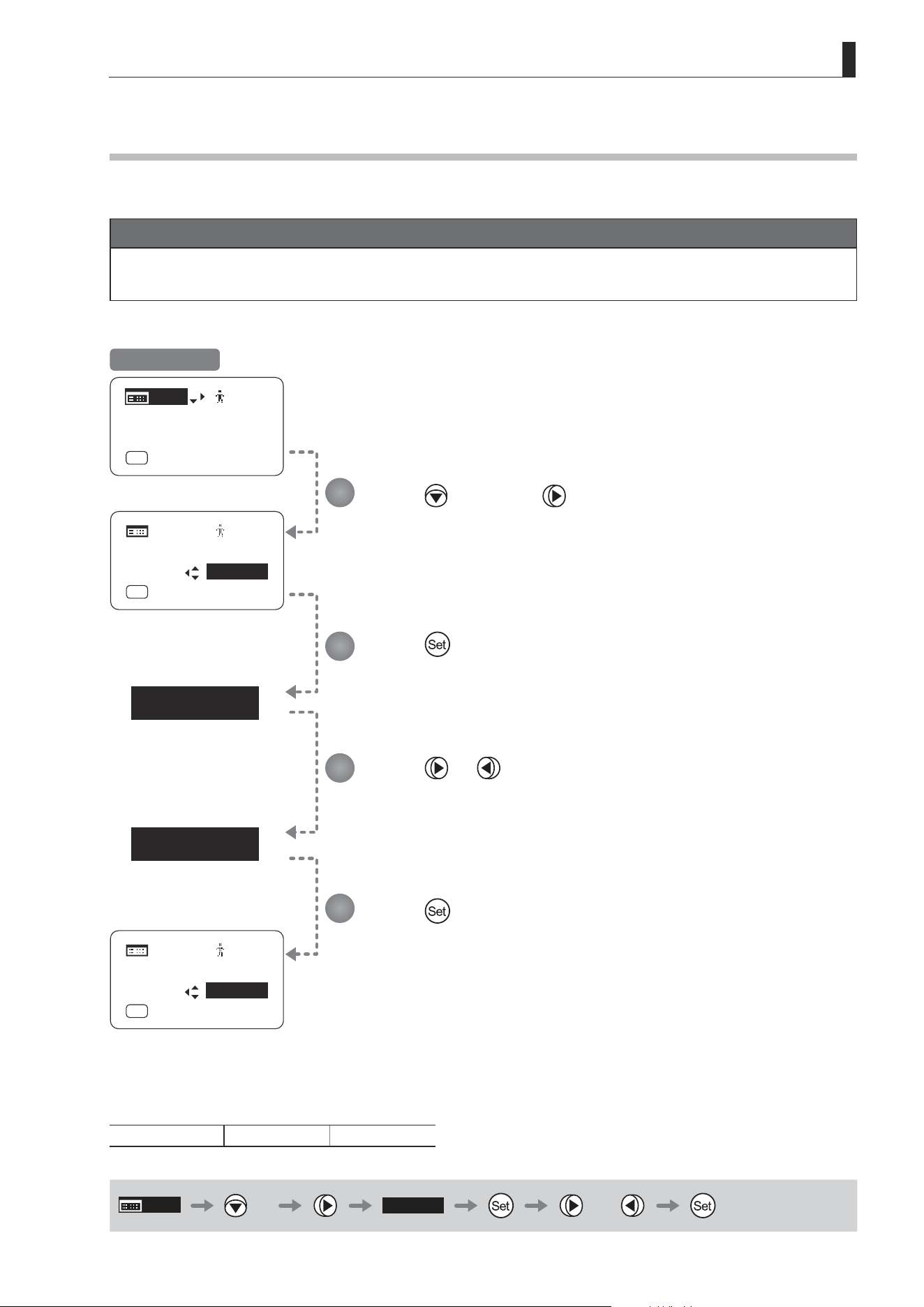
E83
4. Operation in Full Mode
[Trk]
OFF
[Trk]
ON
[ I-Gain ]
[Trk]
OFF
[ I-Gain ]
[Adj]
[]
MENU
1
A
Fr1P
[ Basic ]
[Trk]
OFF
[I-Tq]H
MENU
MENU
[Adj]
[]
1
A
Fr1P
[ Basic ]
[I-Tq]H
[ I-Gain ]
[Trk]
ON
MENU
MENU
[Adj]
[]
A
Fr1P
[ Basic ]
[I-Tq]H
4.1.7 Zoom Tracking ON/OFF [Trk]
Activate or deactivate zoom tracking as needed.
Important
First, switch to the user for whom the settings apply.
(For instructions, see “4.1.3 Switching Users” or “4.2.1 User Screen Settings: Switching Users.”)
Press twice and once.
The previous or default value is highlighted.
Press .
The display starts blinking.
Press or .
Press left or right to switch the function {ON} or {OFF}.
Press .
The display changes from blinking to highlighted, indicating conrmation.
1
2
3
4
Initial Top Screen
Options
(D)
OFF ON
(D): Default value
MENU
× 2
[Trk]
OFF
or
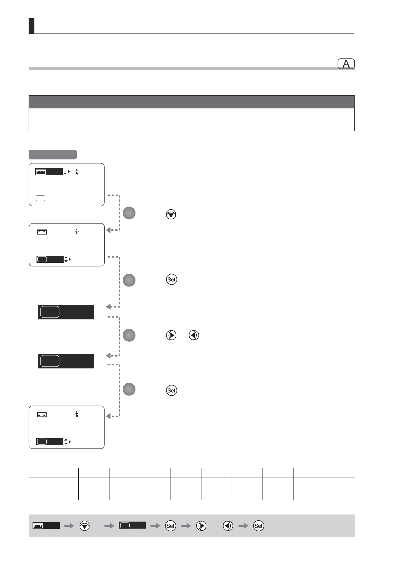
E84
4. Operation in Full Mode
Fr1P
A
VTR
A
Fr1P
A
[ I-Gain ]
[ I-Gain ]
[Adj]
[]
MENU
1
A
Fr1P
[ Basic ]
[Trk]
OFF
[I-Tq]H
MENU
MENU
[Adj]
[]
1
[ Basic ]
[Trk]
OFF
[I-Tq]H
VTR
A
[ I-Gain ]
MENU
MENU
[Adj]
[]
1
[ Basic ]
[Trk]
OFF
[I-Tq]H
4.1.8 Assigning Functions to the AUX Switch
Assign your desired functions to the AUX switch.
Important
First, switch to the user for whom the settings apply.
(For instructions, see “4.1.3 Switching Users” or “4.2.1 User Screen Settings: Switching Users.”)
Options
(D)
Fr1P Fr1F Fr2P Fr2F Sped Shtl NON VTR RET
Description
Framing Preset1
switch
(preset speed)
Framing Preset1
switch
(max. speed)
Framing Preset2
switch
(preset speed)
Framing Preset2
switch
(max. speed)
Speed Preset
switch
Shuttle-Shot
switch
No function VTR switch RET switch
(D): Default value
MENU
× 3
A
Fr1P
or
Press three times.
The previous or default function is highlighted.
Press .
The display starts blinking.
Press or .
Press left or right until you reach the desired function.
Press .
The display changes from blinking to highlighted, indicating conrmation.
1
2
3
4
Initial Top Screen
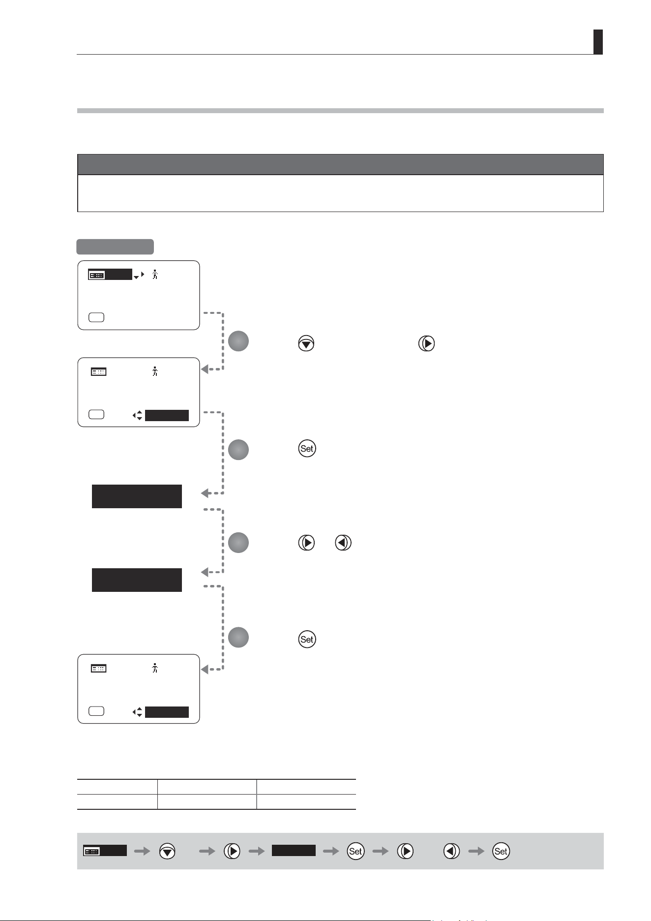
E85
4. Operation in Full Mode
[ I-Tq ] H
[ I-Tq ] L
[ I-Tq ] H
[ I-Gain ]
[Adj]
[]
MENU
1
A
Fr1P
[ Basic ]
[Trk]
OFF
[I-Tq]H
MENU
MENU
[Adj]
[]
1
A
Fr1P
[ Basic ]
[Trk]
OFF
[ I-Gain ]
[ I-Tq ] L
MENU
MENU
[Adj]
[]
1
A
Fr1P
[ Basic ]
[Trk]
OFF
[ I-Gain ]
4.1.9 Specifying Iris Torque [I-Tq]
Specify the desired level of torque in manual control of the iris ring.
Important
First, switch to the user for whom the settings apply.
(For instructions, see “4.1.3 Switching Users” or “4.2.1 User Screen Settings: Switching Users.”)
Press three times and once.
The previous or default function is highlighted.
Press .
The display starts blinking.
Press or .
Press left or right to switch the function to {H} or {L}.
Press .
The display changes from blinking to highlighted, indicating conrmation.
Options
(D)
H L
Description High torque Low torque
(D): Default value
MENU
× 3
[ I-Tq ] H
or
1
2
3
4
Initial Top Screen
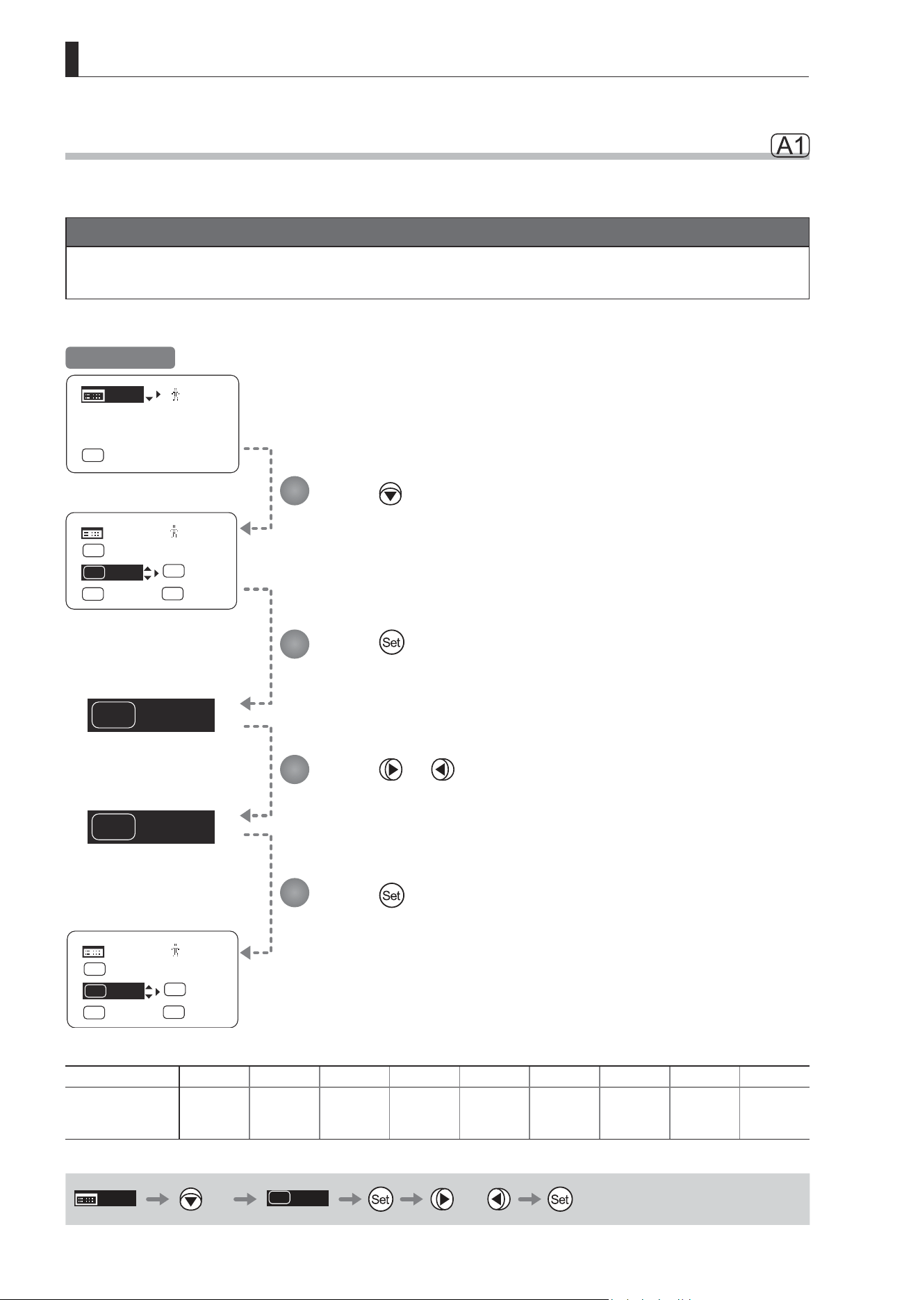
E86
4. Operation in Full Mode
Shtl
A 1
VTR
A 1
Fr1P
VTR
A
V
[]
MENU
MENU
1
Shtl
A 1
Fr1P
A 2
RET
R
Fr1P
VTR
A
V
[]
MENU
MENU
1
VTR
A 1
Fr1P
A 2
RET
R
[ I-Gain ]
[Adj]
[]
MENU
1
A
Fr1P
[ Basic ]
[Trk]
OFF
[I-Tq]H
[I-Tq]H
[I-Tq]H
4.1.10 Assigning Functions to the AUX1 Switch
Assign your desired functions to the AUX1 switch.
Important
First, switch to the user for whom the settings apply.
(For instructions, see “4.1.3 Switching Users” or “4.2.1 User Screen Settings: Switching Users.”)
Initial Top Screen
Press four times.
The previous or default function is highlighted.
Press .
The display starts blinking.
Press or .
Press left or right until you reach the desired function.
Press .
The display changes from blinking to highlighted, indicating conrmation.
1
2
3
4
Options Fr1P Fr1F Fr2P Fr2F Sped
(D)
Shtl NON VTR RET
Description
Framing Preset1
switch
(preset speed)
Framing Preset1
switch
(max. speed)
Framing Preset2
switch
(preset speed)
Framing Preset2
switch
(max. speed)
Speed Preset
switch
Shuttle-Shot
switch
No function VTR switch RET switch
(D): Default value
MENU
× 4
Shtl
A 1
or
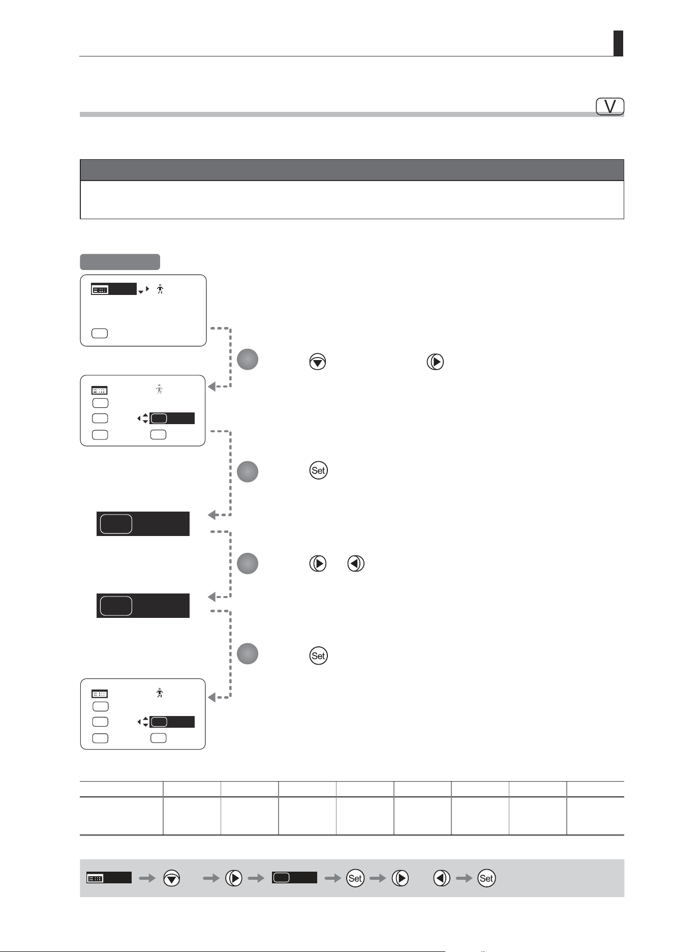
E87
4. Operation in Full Mode
VTR
V
RET
V
VTR
V
Shtl
A 1
[ I-Gain ]
[Adj]
[]
MENU
1
A
Fr1P
[ Basic ]
[Trk]
OFF
[I-Tq]H
Fr1P
A
[]
MENU
MENU
1
Fr1P
A 2
RET
R
[I-Tq]H
RET
V
Shtl
A 1
Fr1P
A
[]
MENU
MENU
1
Fr1P
A 2
RET
R
[I-Tq]H
4.1.11 Assigning Functions to the VTR Switch
Assign your desired functions to the VTR switch.
Important
First, switch to the user for whom the settings apply.
(For instructions, see “4.1.3 Switching Users” or “4.2.1 User Screen Settings: Switching Users.”)
Initial Top Screen
Press four times and once.
The previous or default function is highlighted.
Press .
The display starts blinking.
Press or .
Press left or right until you reach the desired function.
Press .
The display changes from blinking to highlighted, indicating conrmation.
1
2
3
4
Options
(D)
VTR RET Fr1P Fr1F Fr2P Fr2F Sped Shtl
Description VTR switch RET switch
Framing Preset1
switch
(preset speed)
Framing Preset1
switch
(max. speed)
Framing Preset2
switch
(preset speed)
Framing Preset2
switch
(max. speed)
Speed Preset
switch
Shuttle-Shot
switch
(D): Default value
MENU
× 4
VTR
V
or
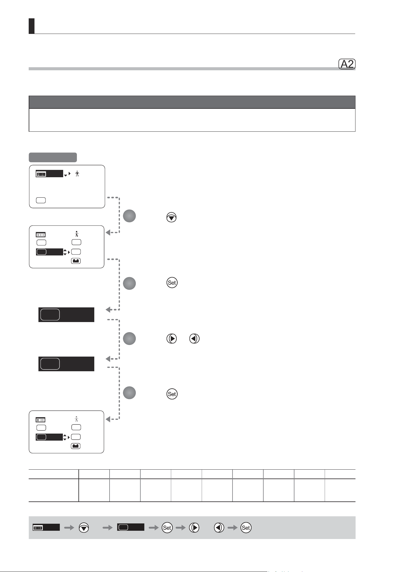
E88
4. Operation in Full Mode
Fr1P
A 2
VTR
A 2
[]
MENU
MENU
1
Fr1P
A 2
RET
R
VTR
V
Shtl
A 1
[ Z.M. ]
[ I-Gain ]
[Adj]
[]
MENU
1
A
Fr1P
[ Basic ]
[Trk]
OFF
[I-Tq]H
Zoom
Zoom
[]
MENU
MENU
1
VTR
A 2
RET
R
VTR
V
Shtl
A 1
[ Z.M. ]
Zoom
Zoom
4.1.12 Assigning Functions to the AUX2 Switch
Assign your desired functions to the AUX2 switch.
Important
First, switch to the user for whom the settings apply.
(For instructions, see “4.1.3 Switching Users” or “4.2.1 User Screen Settings: Switching Users.”)
Initial Top Screen
Press ve times.
The previous or default function is highlighted.
Press .
The display starts blinking.
Press or .
Press left or right until you reach the desired function.
Press .
The display changes from blinking to highlighted, indicating conrmation.
1
2
3
4
Options
(D)
Fr1P Fr1F Fr2P Fr2F Sped Shtl NON VTR RET
Description
Framing Preset1
switch
(preset speed)
Framing Preset1
switch
(max. speed)
Framing Preset2
switch
(preset speed)
Framing Preset2
switch
(max. speed)
Speed Preset
switch
Shuttle-Shot
switch
No function VTR switch RET switch
(D): Default value
MENU
× 5
A 2
Fr1P
or
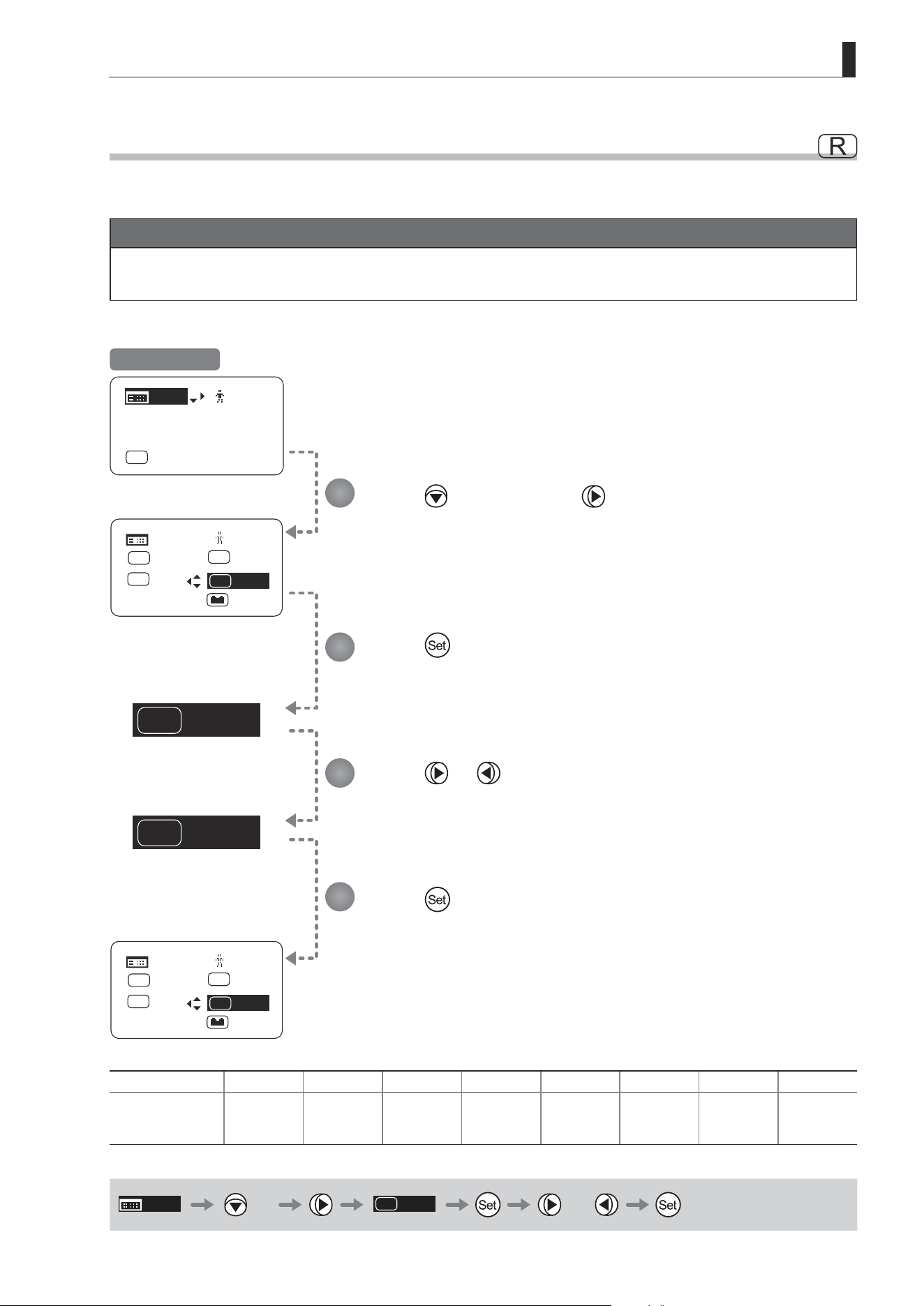
E89
4. Operation in Full Mode
RET
R
Fr2P
R
RET
R
A 2
Fr1P
[ I-Gain ]
[Adj]
[]
MENU
1
A
Fr1P
[ Basic ]
[Trk]
OFF
[I-Tq]H
[]
MENU
MENU
1
VTR
V
Shtl
A 1
[ Z.M. ]
Zoom
Zoom
Fr2P
R
A 2
Fr1P
[]
MENU
MENU
1
VTR
V
Shtl
A 1
[ Z.M. ]
Zoom
Zoom
4.1.13 Assigning Functions to the RET Switch
Assign your desired functions to the RET switch.
Important
First, switch to the user for whom the settings apply.
(For instructions, see “4.1.3 Switching Users” or “4.2.1 User Screen Settings: Switching Users.”)
Initial Top Screen
Press ve times and once.
The previous or default function is highlighted.
Press .
The display starts blinking.
Press or .
Press left or right until you reach the desired function.
Press .
The display changes from blinking to highlighted, indicating conrmation.
1
2
3
4
Options VTR
(D)
RET Fr1P Fr1F Fr2P Fr2F Sped Shtl
Description VTR switch RET switch
Framing Preset1
switch
(preset speed)
Framing Preset1
switch
(max. speed)
Framing Preset2
switch
(preset speed)
Framing Preset2
switch
(max. speed)
Speed Preset
switch
Shuttle-Shot
switch
(D): Default value
MENU
× 5
RET
R
or
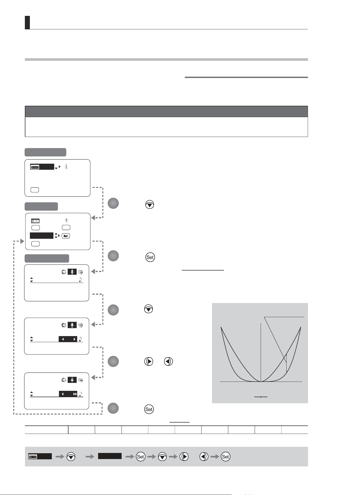
E90
4. Operation in Full Mode
[ Z.M. ]
CurveMode
Zoom
Demand:
Seesaw:
5
5
[]
CurveMode
Zoom
Demand:
Seesaw:
[]
D5
5
CurveMode
Zoom
Demand:
Seesaw:
[]
3
5
[]
MENU
MENU
1
RET
R
Fr1P
A 2
Norm
AM
Zoom
[ I-Gain ]
[Adj]
[]
MENU
1
A
Fr1P
[ Basic ]
[Trk]
OFF
[I-Tq]H
4.1.14 Specifying Zoom Curve Mode [Z.M.]
Specifying Seesaw Switch Responsiveness
Congure the responsiveness of zoom speed adjustment in response to pressing the zoom seesaw switch.
(Note: Another screen is displayed when this setting is congured.)
Important
First, switch to the user for whom the settings apply.
(For instructions, see “4.1.3 Switching Users” or “4.2.1 User Screen Settings: Switching Users.”)
Press seven times.
Your selection is now highlighted.
Press .
The display switches to the CurveMode screen.
Press .
[Seesaw] is underlined.
The previous or default value is
highlighted.
Press or .
Press left or right until you reach
the desired value.
Press .
The display reverts to Screen A.
Options 1 2 3 4
(D)
5 6 7 8 9
(D): Default value
MENU
× 7
[Z.M.]
or
1
2
3
4
5
Initial Top Screen
Screen A
CurveMode Screen
(1)
(9)
Responsiveness to
zoom mode adjustment
Maximum
Zoom Speed
Wide Angle Telephoto
Extent of pressing the zoom seesaw switch
Zoom Direction
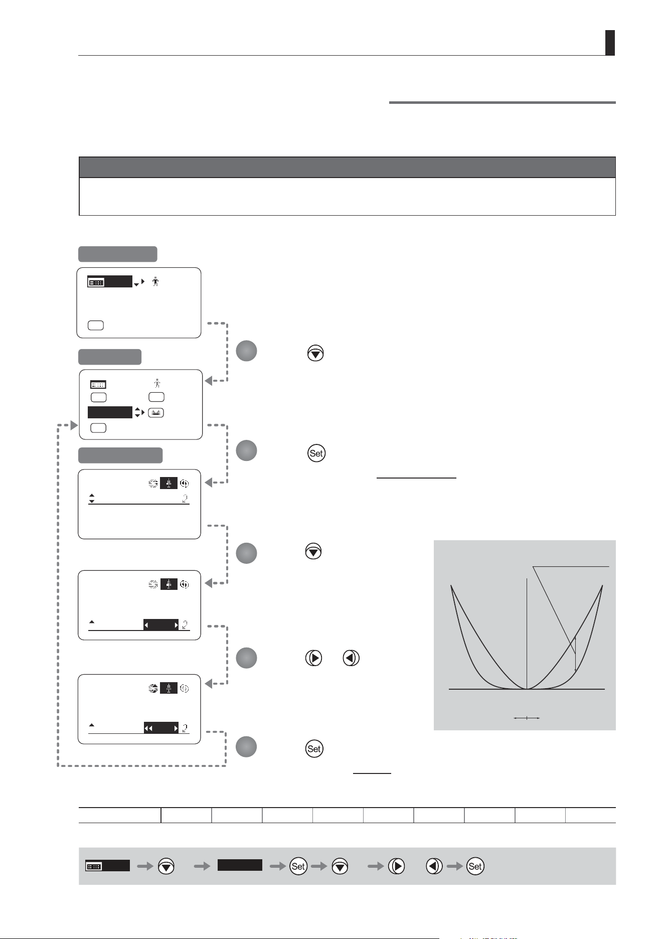
E91
4. Operation in Full Mode
CurveMode
Zoom
Demand:
Seesaw:
[]
CurveMode
Zoom
Demand:
Seesaw:
5
5
[]
CurveMode
Zoom
Demand:
Seesaw:
[]
D5
8
5
5
[ I-Gain ]
[Adj]
[]
MENU
A
Fr1P
[ Basic ]
[Trk]
OFF
[I-Tq]H
[ Z.M. ]
[]
MENU
MENU
1
RET
R
Fr1P
A 2
Norm
AM
Zoom
Specifying Analog Demand Responsiveness
Congure the responsiveness of zoom speed adjustment in response to pressing the analog demand thumb ring.
(Note: Another screen is displayed when this setting is congured.)
Important
First, switch to the user for whom the settings apply.
(For instructions, see “4.1.3 Switching Users” or “4.2.1 User Screen Settings: Switching Users.”)
Press six times.
Your selection is now highlighted.
Press .
The display switches to the CurveMode screen.
Press twice.
[Demand] is underlined.
The previous or default value is
highlighted.
Press or .
Press left or right until you reach
the desired value.
Press .
The display reverts to Screen A.
Options 1 2 3 4
(D)
5 6 7 8 9
(D): Default value
MENU
× 6
[Z.M.]
× 2 or
1
2
3
4
5
Initial Top Screen
Screen A
CurveMode Screen
(1)
(9)
Responsiveness to
zoom mode adjustment
Maximum
Zoom Speed
Wide Angle Telephoto
Extent of tilting the analog demand
Zoom Direction
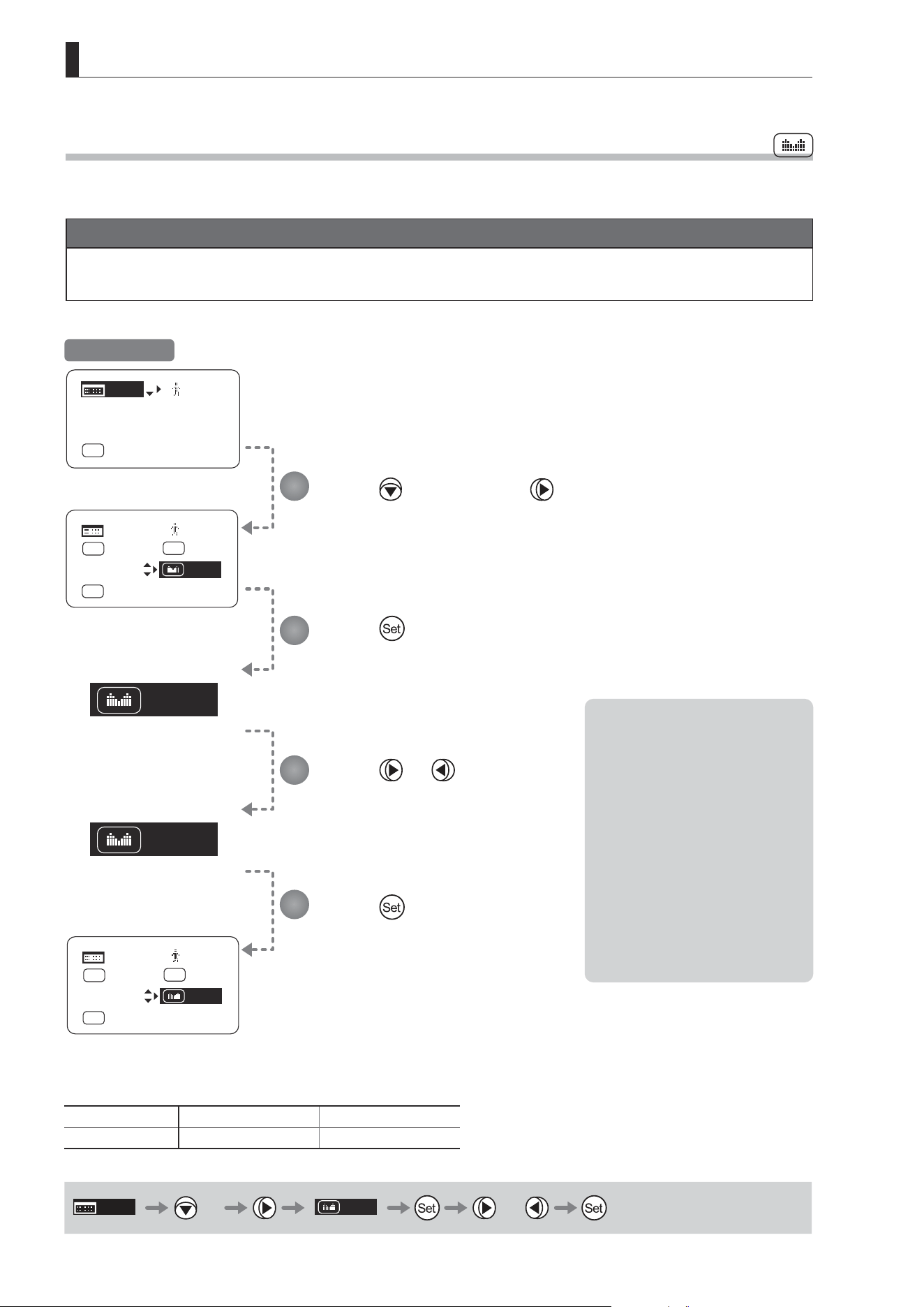
E92
4. Operation in Full Mode
Zoom
Iris
[ Z.M. ]
[ I-Gain ]
[Adj]
[]
MENU
1
A
Fr1P
[ Basic ]
[Trk]
OFF
[I-Tq]H
[]
MENU
MENU
1
RET
R
Fr1P
A 2
Norm
AM
Zoom
[ Z.M. ]
[]
MENU
MENU
1
RET
R
Fr1P
A 2
Norm
AM
Iris
4.1.15 Assigning Functions to the Seesaw
The zoom seesaw switch can be programmed to control either the {Zoom} or {Iris}.
Important
First, switch to the user for whom the settings apply.
(For instructions, see “4.1.3 Switching Users” or “4.2.1 User Screen Settings: Switching Users.”)
Press six times and once.
The previous or default function is highlighted.
Press .
The display starts blinking.
Press or .
Press left or right to switch the function to
{Zoom} or {Iris}.
Press .
The display changes from blinking to
highlighted, indicating conrmation.
Options
(D)
Zoom Iris
Description Zoom operation Iris operation
(D): Default value
MENU
× 6
Zoom
or
1
2
3
4
Initial Top Screen
Note: Note on Iris Assignment
1. The seesaw switch will no
longer control zooming.
2. To control the iris with the
rocker switch, you must set
the iris mode to manual.
3. Press the Telephoto side to
open the iris, or press the
Wide end side to close it.
4. Zoom speed control
adjustments also apply to iris
control, and you can specify
the maximum iris speed. (See
“4.2.5 Zoom Screen Settings:
Specifying Maximum Zoom
Speed Control.)
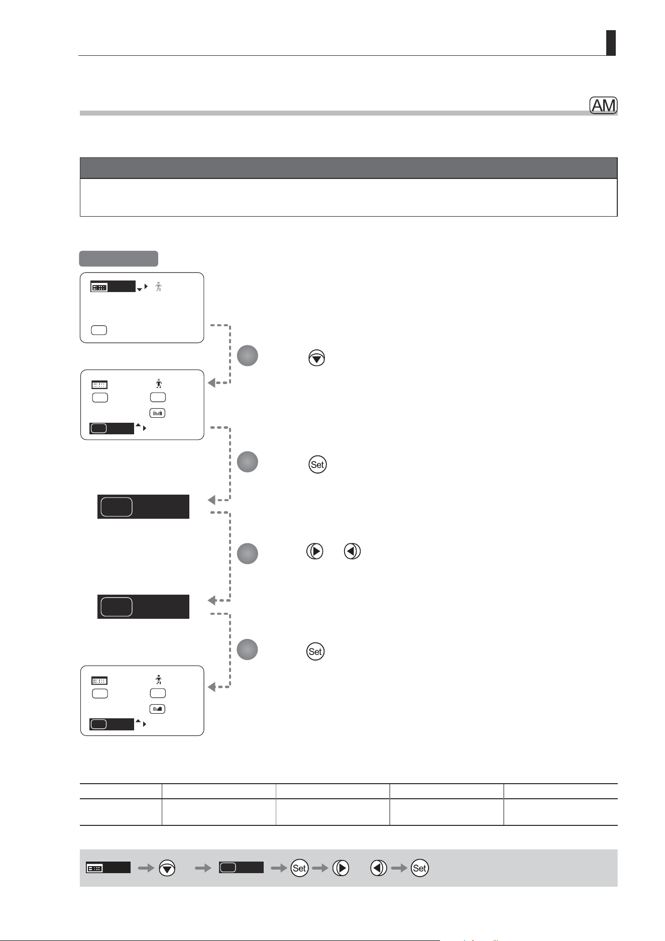
E93
4. Operation in Full Mode
Norm
AM
Reve
AM
[ Z.M. ]
Norm
AM
[]
MENU
MENU
1
RET
R
Fr1P
A 2
Zoom
[ I-Gain ]
[Adj]
[]
MENU
1
A
Fr1P
[ Basic ]
[Trk]
OFF
[I-Tq]H
[ Z.M. ]
Reve
AM
[]
MENU
MENU
1
RET
R
Fr1P
A 2
Zoom
4.1.16 Specifying Iris A/M Switch
The iris A/M switch on the top of the drive unit can be programmed to activate a function of your choice.
Important
First, switch to the user for whom the settings apply.
(For instructions, see “4.1.3 Switching Users” or “4.2.1 User Screen Settings: Switching Users.”)
Press seven times.
The previous or default function is highlighted.
Press .
The display starts blinking.
Press or .
Press left or right until you reach the desired function.
Press .
The display changes from blinking to highlighted, indicating conrmation.
Options
(D)
Norm Reve Auto Manu
Description
Normal operation
A : Auto / M : Manual
Reverse operation
A : Manual / M : Auto
Auto only
A : Auto / M : Auto
Manual only
A : Manual / M : Manual
(D): Default value
MENU
× 7
Norm
AM
or
1
2
3
4
Initial Top Screen
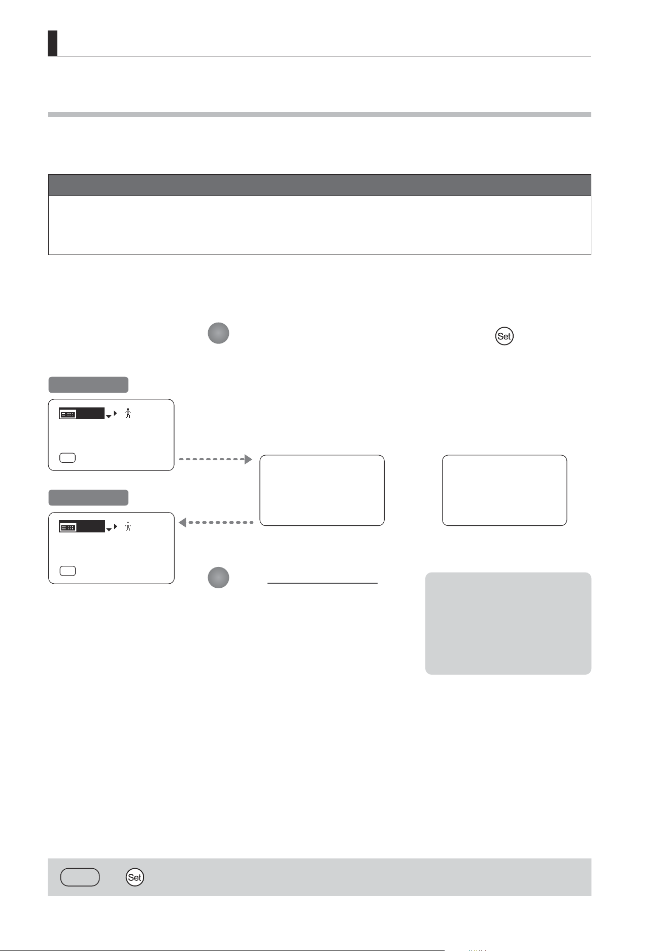
E94
4. Operation in Full Mode
User 0
Reset Now
Escape To User 0
[ I-Gain ]
[Adj]
[]
MENU
1
A
Fr1P
[ Basic ]
[Trk]
OFF
[I-Tq]H
[ I-Gain ]
[Adj]
[]
MENU
0
A
Fr1P
[ Basic ]
[Trk]
OFF
[I-Tq]H
[
DISPLAY
and ] 2 seconds
4.1.17 Escape Operation
Instantly jump to user 0, with default settings, from the current user (0–9).
Note
1. Not available when settings are locked.
2. The following settings remain the same even after jumping to user 0.
Auto and remote iris gain values, encoder output setting, and camera follow voltage adjustments
Hold down both the Display switch and for at least
2 seconds.
One of the following messages is displayed, depending on the current user before
the operation.
User 0 : User 0 Reset Now
User 1–9 : Escape To User 0
The Initial Top screen is
displayed.
1
2
Desired Screen
Initial Top Screen
From User 0 From Users 1–9
or
Note: Initial User When Restarted
After restarting, control
reverts to the user before this
operation.
However, if you switched users
after this operation, control
reverts to that user.
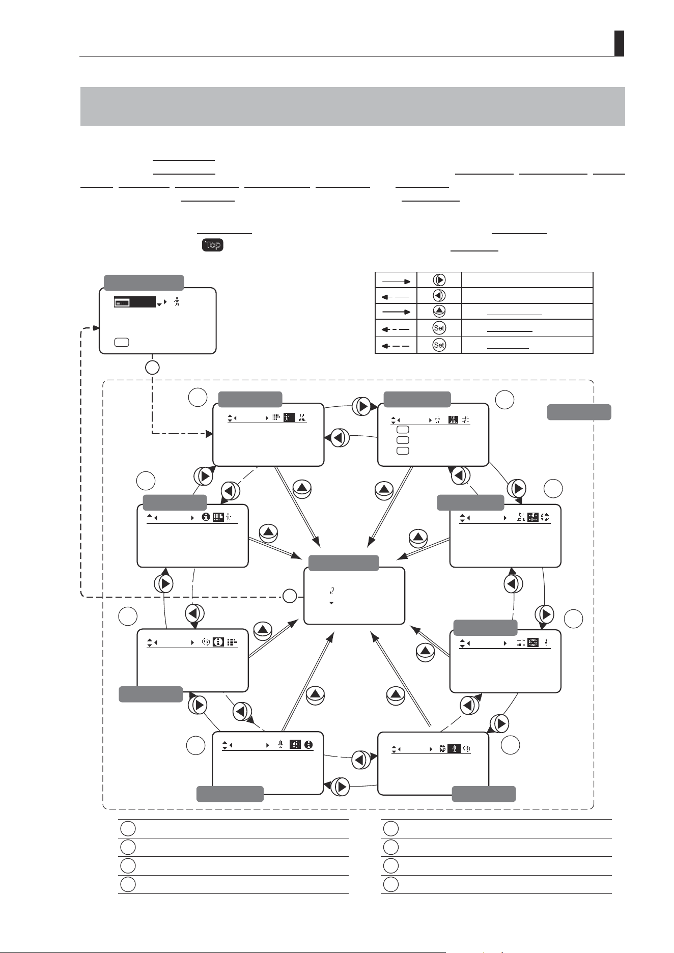
E95
4. Operation in Full Mode
Iris
[]
[ I-Gain ]
Torque:High
Comp: ON
Fol.
Iris:
Zoom:
Focus:
0940
0527
0011
1
Frame1:
Preset
Zoom
Frame2:Zoom
ZSpeed:800
: Go Top
: Back
Set
Set
1
2
3
4
5
6
7
8
]
CurveMode
Focus
[]
Mode:
User
Full
Name:
No.:
1
--------
Switch
1
AUX2:
A
A 1
AUX1:
A 2
Fr1P
AUX:
Fr1P
Shtl
Movement
Zoom
[]
1
Tracking:
OFF
CurveMode
Info
3D:
OFF
S/N
Encoder:
OFF
[ I-Gain ]
[Adj]
[]
MENU
1
A
Fr1P
[ Basic ]
[Trk]
OFF
[I-Tq]H
4.2 Conguration from the Menu Screen
In Full mode, you can view and congure 38 setting items and a “follow” screen with three setting items that have relative
values from the Menu screen.*
Specically, the Menu screen in Full mode is organized into 8 screens by function: User screen, Switch screen, Preset
screen, Iris screen, Zoom screen, Focus screen, Info screen, and Fol. screen.
Select [MENU] on the Top screen and press the Set key to access the User screen initially. Press left or right to access
the 7 other screens. (See the following gure.)
*: There is no single
Menu screen. Instead, these 8 screens are collectively referred to as the Menu screen.
Setting items labeled
Top
next to the function title can also be congured from the Top screen.
1
User Screen................................................ 4.2.1
5
Zoom Screen .............................................. 4.2.5
2
Switch Screen............................................. 4.2.2
6
Focus Screen ............................................. 4.2.6
3
Preset Screen ............................................. 4.2.3
7
Info Screen ................................................. 4.2.7
4
Iris Screen .................................................. 4.2.4
8
Fol. Screen ................................................. 4.2.8
To the next screen clockwise
To the next screen counterclockwise
To the Go Top screen
To the User screen
To the Top screen
Initial Top Screen
User Screen
Fol. Screen
Go Top Screen
Preset Screen
Switch Screen
Menu Screen
Iris Screen
Zoom ScreenFocus Screen
Info Screen

E96
4. Operation in Full Mode
4.2.1 User Screen Settings
For details on users available in Full mode, see “4.1.3 Switching Users.”
The following setting items can be congured on the User screen.
Switching Modes
Switching Users
Top
Naming Users
Resetting Values
(1) Resetting One User’s Settings
(2) Resetting All Users’ Settings
Copying Settings Between Individual Users
Copying Settings Between Lenses
(1) Copying One User’s Settings to Another Lens
(2) Copying All Users’ Settings to Another Lens
(3) Responding to Errors
Locking Functions
Items labeled
Top
can also be modied from the Top screen.
User Screen in Full Mode
Mode:
User
Full
Name:
No.:
1
--------
1

E97
4. Operation in Full Mode
Mode:
User
Full
1
No. :
User
1
Name:
Mode:
1
Basic
Mode:
User
Full
Name:
No.:
1
--------
1
Name:
No.:
--------
1
[ I-Gain ]
[Adj]
[]
MENU
1
A
Fr1P
[ Basic ]
[Trk]
OFF
[I-Tq]H
Press .
The display switches to the User screen.
Press .
[Mode] is underlined.
The previous mode is highlighted.
Press or .
Press left or right until you reach the desired mode.
Switching Modes
Switch to Basic or Analog mode as needed.
Important
The new mode setting is retained even after the lens is turned o.
Initial Top Screen
User Screen
Options
(D)
Basic Full Analog
Save Settings Basic Mode Full Mode Analog Mode
(D): Default value
MENU
User
1
or
1
2
3
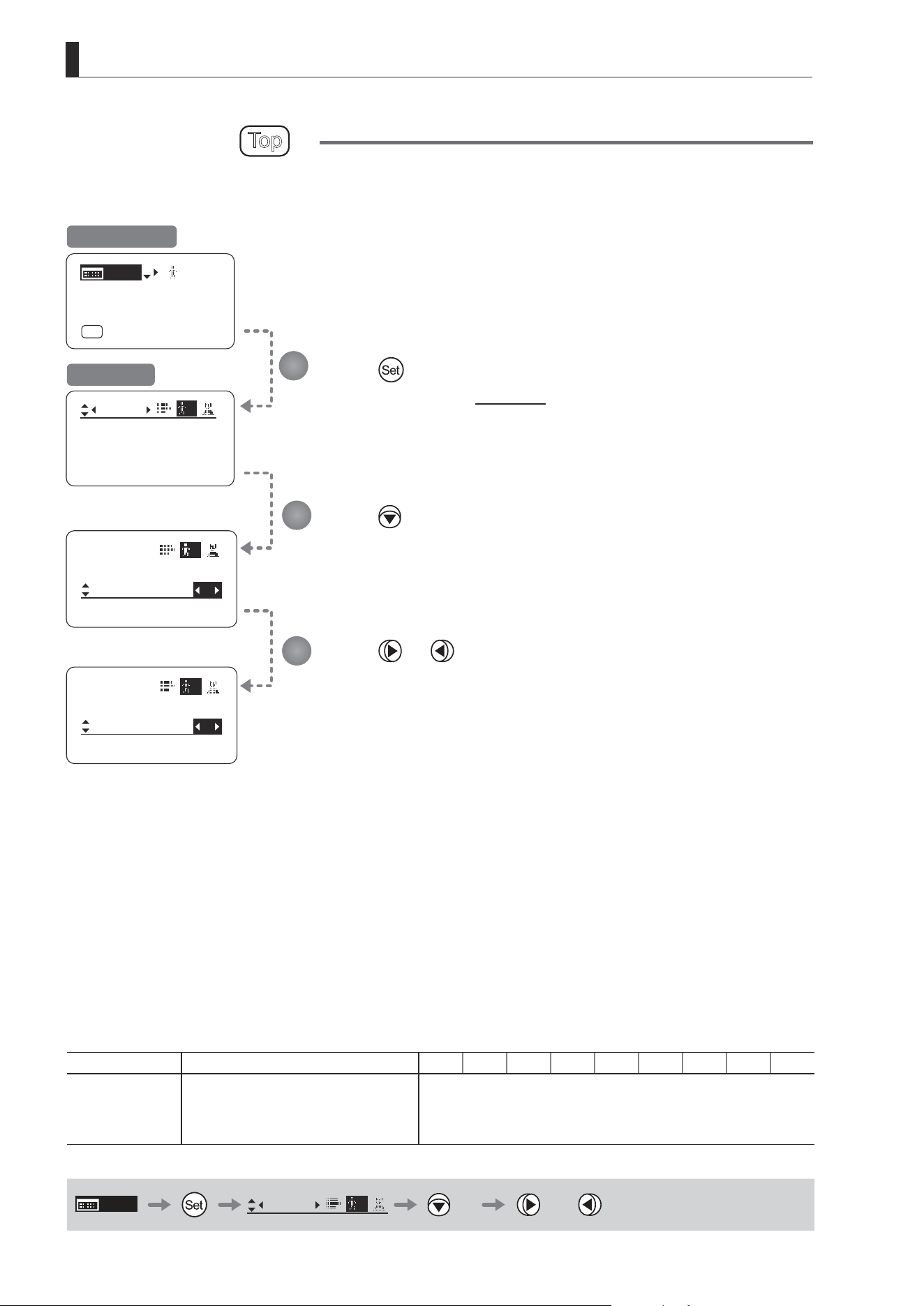
E98
4. Operation in Full Mode
Mode:
User
Full
Name:
No.:
1
--------
1
No. : 2
Mode:
User
1
Name:
--------
Full
No. : 1
Mode:
User
1
Name:
--------
Full
[ I-Gain ]
[Adj]
[]
MENU
1
A
Fr1P
[ Basic ]
[Trk]
OFF
[I-Tq]H
Switching Users
Top
Switch Users (0–9) as needed. To congure settings for individual users, switch to that user number.
Press .
The display switches to the User screen.
Press twice.
[No.] is underlined.
The previous or default value is highlighted.
Press or .
Press left or right until you reach the desired mode.
Initial Top Screen
User Screen
Options 0
(D)
1 2 3 4 5 6 7 8 9
Save Settings
Not supported
Although settings cannot be saved, they can be
changed temporarily.
Switching users or turning the lens o will restore
default values.
Can be saved for each user
(D): Default value
MENU
User
1
× 2 or
1
2
3
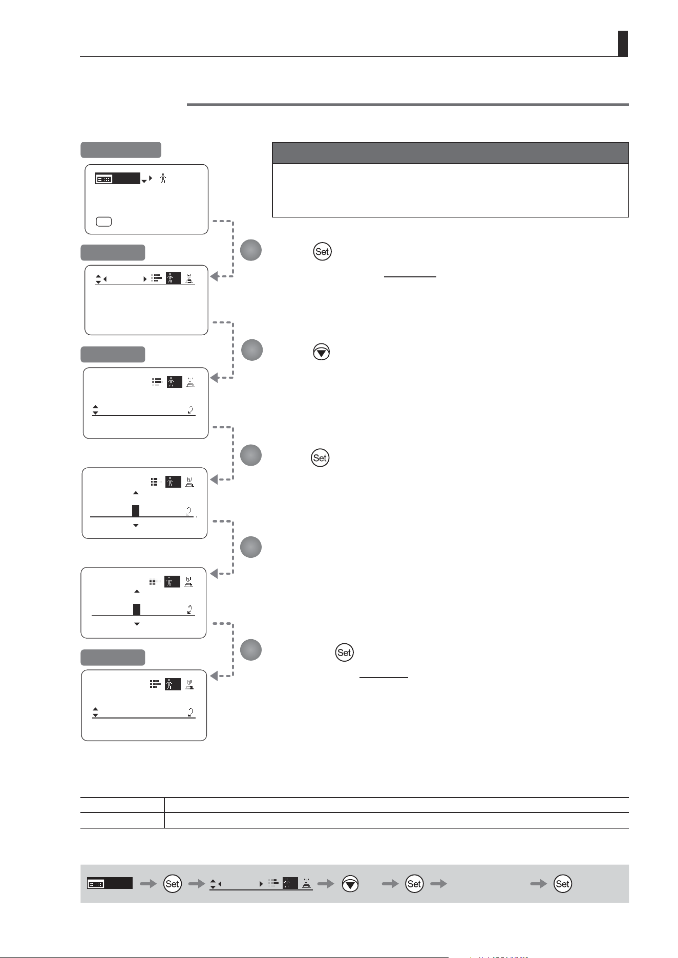
E99
4. Operation in Full Mode
No. :
Name:
ResetAll
Name
Name:
㧙㧙㧙㧙㧙㧙㧙㧙
No. :
User
Name:
ResetAll
1
1
A 㧙㧙㧙㧙㧙㧙㧙
User
1
Mode:
User
Full
Name:
No.:
1
--------
1
User
1
--------
1
[ I-Gain ]
[Adj]
[]
MENU
1
A
Fr1P
[ Basic ]
[Trk]
OFF
[I-Tq]H
Name
User
Name: A
1
㧙㧙㧙㧙㧙㧙㧙
Naming Users
Users can be named, as needed.
Important
First, switch to the user for whom the settings apply.
(For instructions, see “4.1.3 Switching Users” or “4.2.1 User Screen
Settings: Switching Users.”)
Press .
The display switches to the User screen.
Press three times.
[Name] is underlined.
Press .
The rst dash is highlighted, indicating that you can edit it.
Enter the name.
Entering Name
Press up/down to nd characters and left/right to move the cursor or make corrections.
Press the to conrm the name.
The display reverts to Title: Name.
1
2
3
4
5
Initial Top Screen
User Screen
Title: Name
Title: Name
Options
_
(D)
– A B C D E F G H I J K L M N O P Q R S T U V W X Y Z a b c d e f g h i j k l m n o p q r s t u v w x y z 0 1 2 3 4 5 6 7 8 9
Max. Digits 8
(D) : Default value
_ : Space
MENU
User
1
× 3 Entering Name
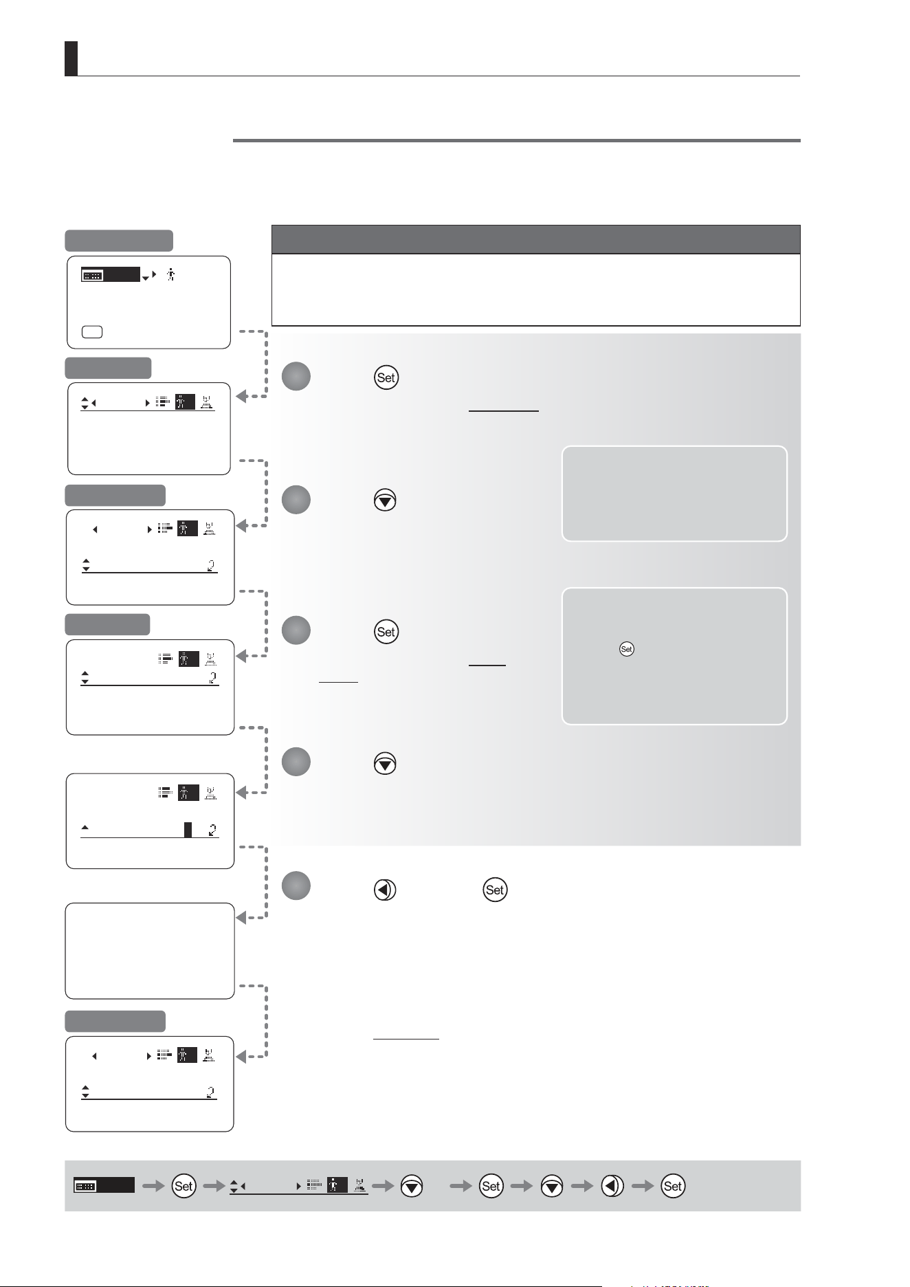
E100
4. Operation in Full Mode
User 1
Reset Now.
ResetAll
User
User:
y/n
AllUser:
y/n
AllUser:
y/n
ResetAll
User
User:
y/n
User
Copy
ResetAll
1
1
1
Mode:
User
Full
Name:
No.:
1
--------
1
Name:
--------
User
Copy
ResetAll
1
Name:
--------
[ I-Gain ]
[Adj]
[]
MENU
1
A
Fr1P
[ Basic ]
[Trk]
OFF
[I-Tq]H
MENU
User
1
× 4
Resetting Values
(1) Resetting One User’s Settings
Reset a user’s settings to default values as needed.
Note: Iris gain values, encoder
output setting, and camera
follow voltage adjustments are
not reset. The current value is
retained.
Press and then .
Press .
The display switches to the User screen.
Press four times.
[ResetAll] is underlined.
Press .
The display switches to the Reset
screen.
Press .
A conrmation message is displayed about resetting information for the selected user.
Note: You can cancel resetting and
restore the original values
at any time before pressing
in step 5. To return to the
previous screen, press up. To
cancel resetting and turn o
the display, press the Display
switch.
User Screen
Title: Reset
Title: Reset
Reset Screen
1
2
3
4
5
Initial Top Screen
Important
First, switch to the user for whom the settings apply.
(For instructions, see “4.1.3 Switching Users” or “4.2.1 User Screen Settings:
Switching Users.”)
After a message is displayed indicating that resetting is in progress, the display
reverts to Title: Reset.
The settings have now been reset.
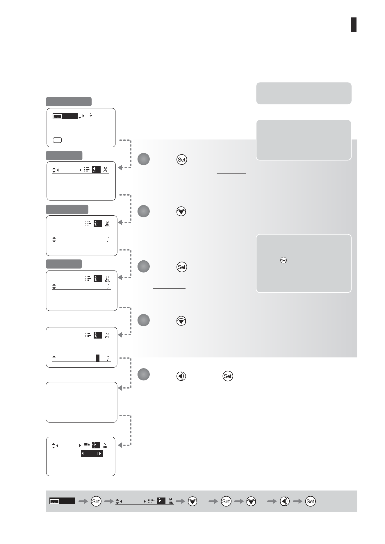
E101
4. Operation in Full Mode
Name:
User
ResetAll
Copy
1
All User
Reset Now.
ResetAll
User
User:
AllUser:
1
y/n
y/n
Mode:
User
Full
Name:
No.:
1
--------
1
Mode:
User
Access:
1
Unlock
1
ResetAll
㧙㧙㧙㧙㧙㧙㧙㧙
ResetAll
User
User:
AllUser:
1
y/n
y/n
[ I-Gain ]
[Adj]
[]
MENU
1
A
Fr1P
[ Basic ]
[Trk]
OFF
[I-Tq]H
Basic
MENU
User
1
× 4 × 2
(2) Resetting All Users’ Settings
Reset all users’ settings to default values as needed.
Note: You can cancel resetting and
restore the original values
at any time before pressing
in step 5. To return to the
previous screen, press up. To
cancel resetting and turn o
the display, press the Display
switch.
Note: Iris gain values, encoder
output setting, and camera
follow voltage adjustments are
not reset. The current value is
retained.
Note: There is no need to switch
users.
Press and then .
Press .
The display switches to the User screen.
Press four times.
[ResetAll] is underlined.
Press .
The display switches to the
Reset screen.
Press twice.
A conrmation message is displayed about resetting information for the all users.
User Screen
Title: Reset
Reset Screen
1
2
3
4
5
Initial Top Screen
Resetting is nished once the message during resetting is no longer displayed.
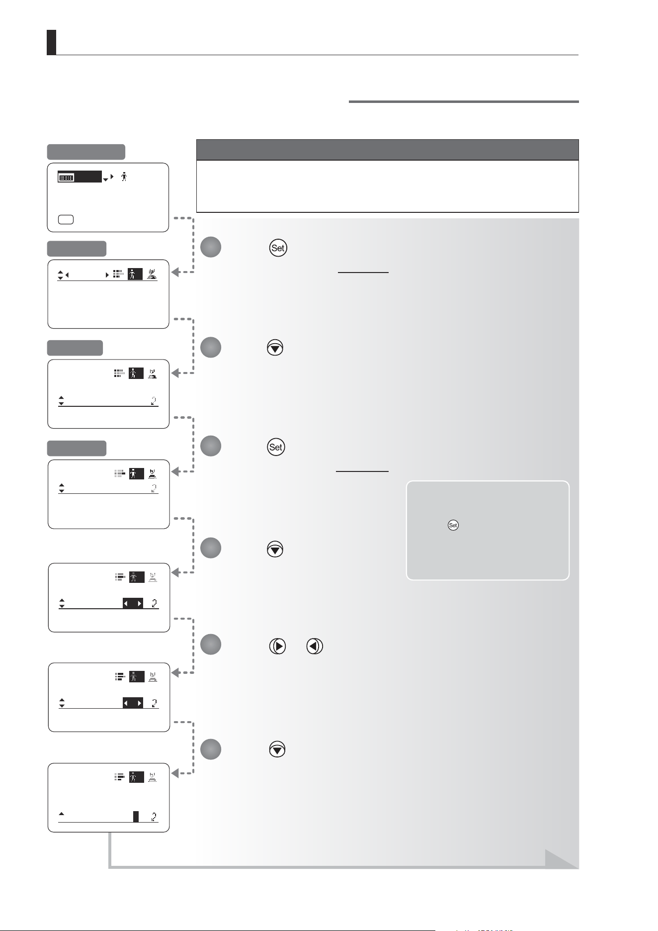
E102
4. Operation in Full Mode
Copy
User
To No. :
Copy:
1
y/n
1
Copy
User
To No. :
Copy:
1
y/n
3
Copy
User
To No. :
Copy:
1
3
y/n
ResetAll
User
Copy
ToOtherLens
1
Copy
User
To No. :
Copy:
1
1
y/n
Mode:
User
Full
Name:
No.:
1
--------
1
[ I-Gain ]
[Adj]
[]
MENU
1
A
Fr1P
[ Basic ]
[Trk]
OFF
[I-Tq]H
Note: You can cancel copying and
restore the original values
at any time before pressing
in step 7. To return to the
previous screen, press up. To
cancel copying and turn o
the display, press the Display
switch.
Press or .
Press left or right until you reach the user to copy settings to.
Press .
[Copy] is underlined, and you can select {y} (yes) or {n} (no).
Press .
The display switches to the User screen.
Press ve times.
[Copy] is underlined.
Press .
The display switches to the Copy screen.
Press .
[To No.] is underlined.
1
2
3
4
5
6
Initial Top Screen
User Screen
Screen A
Copy Screen
Continued on next page
Copying Settings Between Individual Users
Settings congured for one user can be copied to another user.
Important
First, switch to the user for whom the settings apply.
(For instructions, see “4.1.3 Switching Users” or “4.2.1 User Screen Settings:
Switching Users.”)
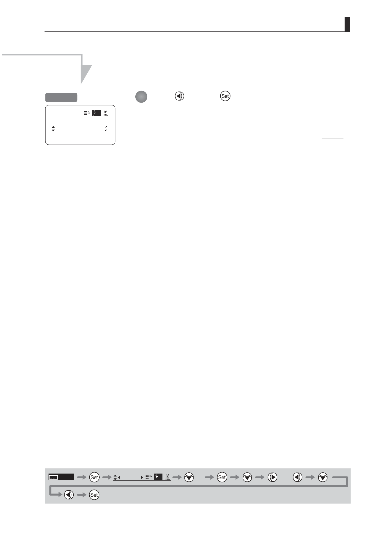
E103
4. Operation in Full Mode
ResetAll
User
Copy
ToOtherLens
1
Press and then .
Settings are copied to the specied user number, and the display reverts to Screen A.
7
MENU
User
1
× 5 or
Screen A
Continued from previous page
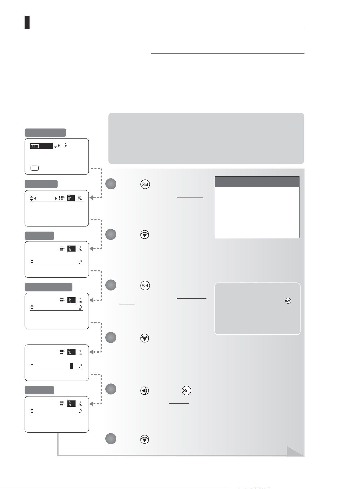
E104
4. Operation in Full Mode
ToOtherLens
User
Connect:
1
y/n
ToOtherLens
User
Connect:
1
y/n
Mode:
User
Full
Name:
No.:
1
--------
1
ToOtherLens
User
UserCopy :
AllCopy :
1
y/n
y/n
User
Copy
ToOtherLens
1
Access:
Unlock
[ I-Gain ]
[Adj]
[]
MENU
1
A
Fr1P
[ Basic ]
[Trk]
OFF
[I-Tq]H
Copying Settings Between Lenses
Setting information can be copied between information displays of drive units mounted on the display. You can copy
either settings for individual users or for all users. Copying requires a dedicated cable, sold separately. For details,
contact Canon or your dealer.
(1) Copying One User’s Settings to Another Lens
Note: Required Preparation
1. Plug one end of the dedicated cable (20 pin–20 pin) into the source lens and the other
end into the 20-pin connector of the zoom/focus remote of the target lens.
2. Turn on the source and target lenses.
3. Press the Display switch on the source lens to turn on the display. (Leave the source
lens display o.)
Note: You can cancel copying and
restore the original values at
any time before pressing
in step 11. To return to the
previous screen, press up. To
cancel copying and turn o
the display, press the Display
switch.
Important
First, switch to the user for whom
the settings apply.
(For instructions, see “4.1.3
Switching Users” or “4.2.1 User
Screen Settings: Switching
Users.”)
Press and then .
The display switches to Screen B.
Press .
The display switches to the User screen.
Press six times.
[ToOtherLens] is underlined.
Press .
The display switches to the ToOtherLens
screen.
Press .
[Connect] is underlined, and you can
select {y} (yes) or {n} (no).
Press .
1
2
3
4
6
5
Initial Top Screen
User Screen
Screen A
ToOtherLens Screen
Screen B
Continued on next page
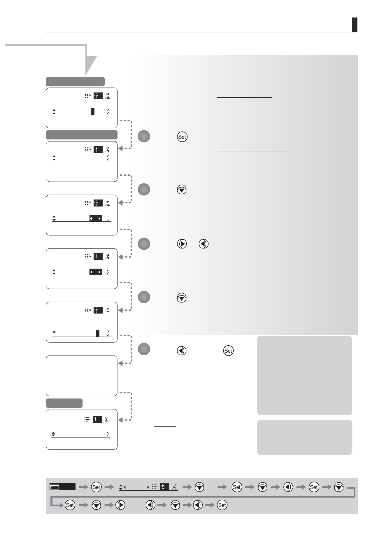
E105
4. Operation in Full Mode
ToOtherLens
User
To No. :
Copy:
1
1
y/n
ToOtherLens
User
To No. :
Copy:
1
y/n
3
Now Data Copy
Please Wait...
ToOtherLens
User
To No. :
Copy:
1
y/n
1
User
Copy
ToOtherLens
1
Access:
Unlock
ToOtherLens
User
To No. :
Copy:
1
y/n
3
ToOtherLens
User
UserCopy :
AllCopy :
1
y/n
y/n
Continued from previous page
Note: If copying fails, an error
message is displayed.
Respond as described in “(3)
Responding to Errors.”
*1: Pressing the Set key in this
step begins the copying
process. Note that once
copying begins, you cannot
restore the original settings.
*2: To avoid problems during
copying, do not operate
controls or press the Display
switch on the source or target
lenses. Do not perform other
operations.
MENU
User
1
× 6
or
Press and then .
Press .
The display switches to the Target user selection screen.
The display switches to the Copy selection screen.
Press .
[To No.] is underlined.
Press or .
Press left or right until you reach the number of the user on the target lens to copy
settings to.
Press .
[Copy] is underlined, and you can select {y} (yes) or {n} (no).
7
8
9
10
11
Copy Selection Screen
Target User Selection Screen
Screen A
*1
After a message is displayed
indicating that copying is in
progress, the display reverts to
Screen A.
The settings have now been
copied between lenses.
*2
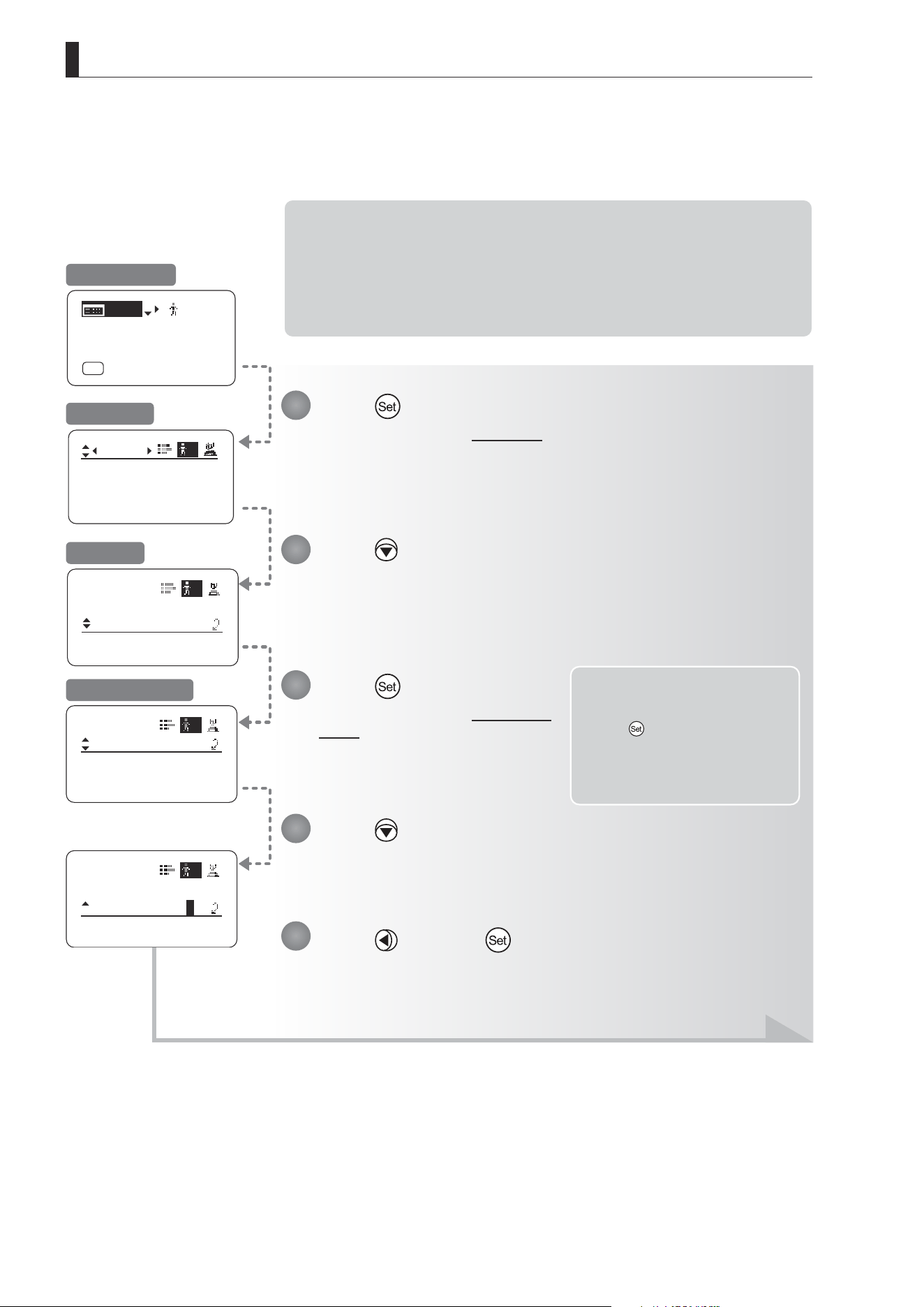
E106
4. Operation in Full Mode
ToOtherLens
User
Connect:
1
y/n
ToOtherLens
User
Connect:
1
y/n
Mode:
User
Full
Name:
No.:
1
--------
1
User
Copy
ToOtherLens
1
Access:
Unlock
[ I-Gain ]
[Adj]
[]
MENU
1
A
Fr1P
[ Basic ]
[Trk]
OFF
[I-Tq]H
(2) Copying All Users’ Settings to Another Lens
Copying requires a dedicated cable, sold separately. For details, contact Canon or your dealer.
Note: Required Preparation
1. Plug one end of the dedicated cable (20 pin–20 pin) into the source lens and the other
end into the 20-pin connector of the zoom/focus remote of the target lens.
2. Turn on the source and target lenses.
3. Press the Display switch on the source lens to turn on the display. (Leave the source
lens display o.)
Note: You can cancel copying and
restore the original values
at any time before pressing
in step 9. To return to the
previous screen, press up. To
cancel copying and turn o
the display, press the Display
switch.
Press and then .
Press .
The display switches to the User screen.
Press six times.
[ToOtherLens] is underlined.
Press .
The display switches to the ToOtherLens
screen.
Press .
[Connect] is underlined, and you can select {y} (yes) or {n} (no).
1
2
3
4
5
Initial Top Screen
User Screen
Screen A
ToOtherLens Screen
Continued on next page
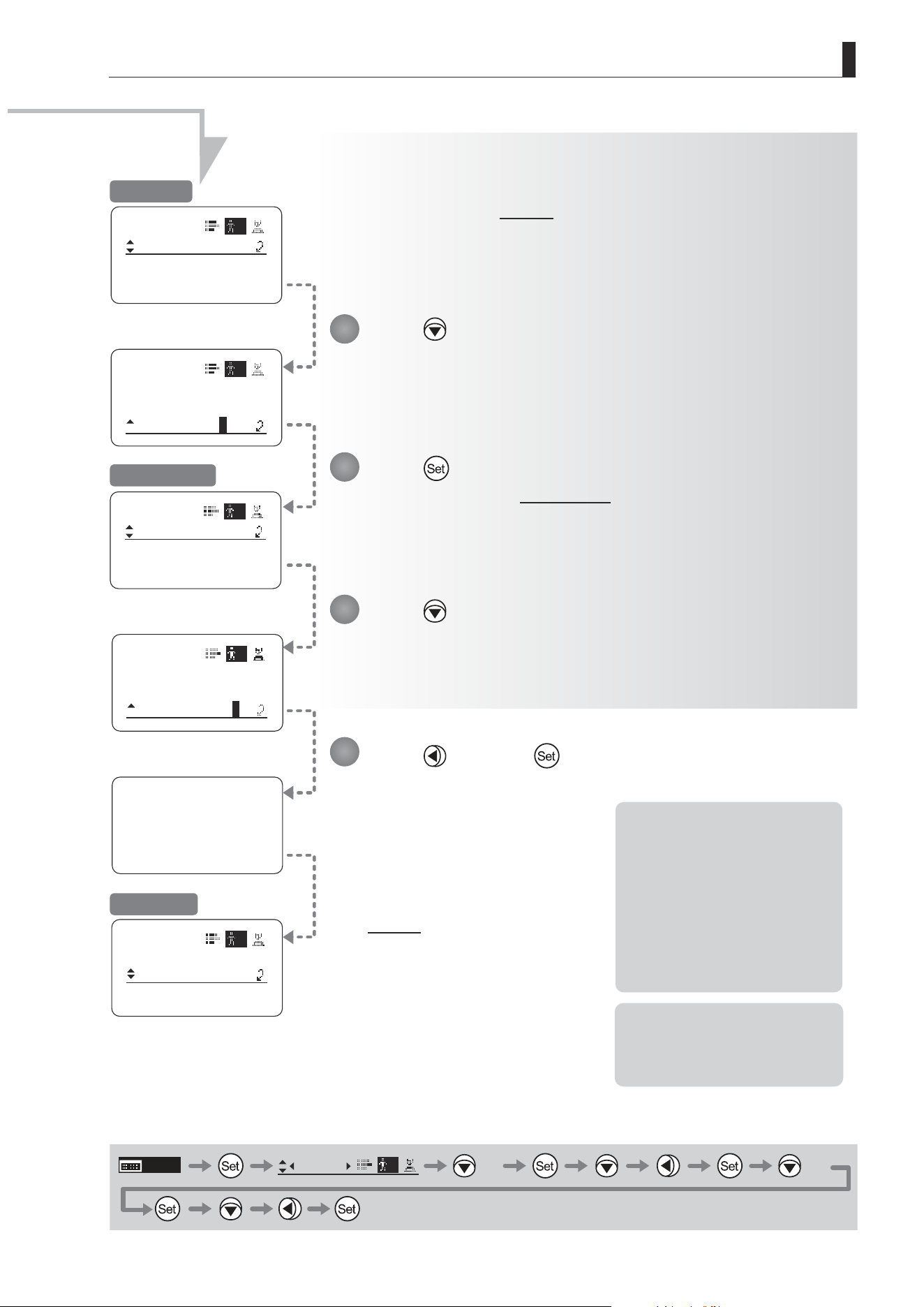
E107
4. Operation in Full Mode
ToOtherLens
User
ToAllUser
Copy:
1
y/n
Now Data Copy
Please Wait...
ToOtherLens
User
ToAllUser
Copy:
1
y/n
ToOtherLens
User
UserCopy :
AllCopy :
1
y/n
y/n
y/n
ToOtherLens
User
UserCopy :
AllCopy :
1
y/n
User
Copy
ToOtherLens
1
Access:
Unlock
Note: If copying fails, an error
message is displayed.
Respond as described in “(3)
Responding to Errors.”
*1: Pressing the Set key in this
step begins the copying
process. Note that once
copying begins, you cannot
restore the original settings.
*2: To avoid problems during
copying, do not operate
controls or press the Display
switch on the source or target
lenses. Do not perform other
operations.
MENU
User
1
× 6 × 2
Press and then .
The display switches to Screen B.
Press twice.
[AllCopy] is underlined, and you can select {y} (yes) or {n} (no).
Press .
The display switches to the AllCopy screen.
Press .
[Copy] is underlined, and you can select {y} (yes) or {n} (no).
6
7
8
9
Screen B
AllCopy Screen
Screen A
*1
Continued from previous page
After a message is displayed
indicating that copying is in
progress, the display reverts to
Screen A.
The settings have now been
copied between lenses.
*2
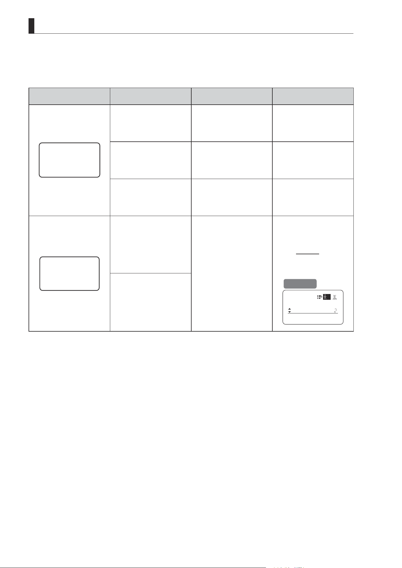
E108
4. Operation in Full Mode
(3) Responding to Errors
If copying between lenses fails, check the following.
Error Screen Checking Item Problem Responding
Lens Connect
Error!!
Conrm that the dedicated cable
(20 pin–20 pin) is connected.
Settings cannot be copied
between lenses unless the
cable is connected.
Securely connect the cable
between the source and target
lenses, and follow the steps to
copy again, from the start.
Conrm that the target lens is
on.
Settings cannot be copied
unless both the source and
target lenses are on.
Turn on both the source and
target lenses, and follow the
steps to copy again, from the
start.
Conrm that the drive unit of the
target lens is the same model.
Settings cannot be copied
between lenses of dierent
generations of drive units.
Contact Canon or your dealer
for details on models of drive
unit that can be used to copy
settings.
Copy Error!!
Conrm that the dedicated cable
(20 pin–20 pin) is connected.
The message at left is displayed
if the lenses are disconnected
during copying, if a power
outage occurs, or if a lens is
turned o. In this case, copying
is interrupted, which prevents
the settings from being copied
correctly.
Conrm that the source and
target lenses are on, and that
the cable is securely connected.
Press the Display switch to
return to Screen A, and follow
the steps to copy again, from
the start.
Conrm that the source and
target lenses are on.
Screen A
User
Copy
ToOtherLens
1
Access:
Unlock
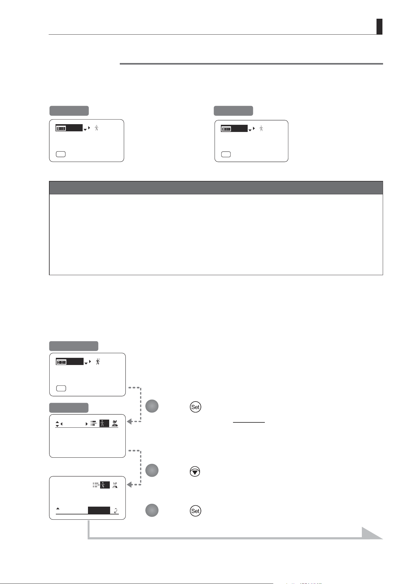
E109
4. Operation in Full Mode
Mode:
User
Full
Name:
No.:
1
--------
1
User
1
Access:
Unlock
Copy
ToOtherLens
[ I-Gain ]
[Adj]
[]
MENU
1
A
Fr1P
[ Basic ]
[Trk]
OFF
[I-Tq]H
(1) Locking Settings
Lock Functions
To ensure that congured functions cannot easily be changed, you can lock the settings of certain functions. Once
functions are locked, they are locked for all users.
For instructions on locking settings in Analog mode, see “5. Operation in Analog Mode.”
[ I-Gain ]
[Adj]
[]
MENU
1
A
Fr1P
[ Basic ]
[Trk]
OFF
[I-Tq]H
[ I-Gain ]
[Adj]
[]
MENU
Lock
A
Fr1P
[ Basic ]
[Trk]
OFF
[I-Tq]H
Unlocked Locked
Note
1. User numbers 0–9 in the user number eld indicate users that are unlocked.
“Lock” in the user number eld indicate users that are locked.
2. In lock mode, only the following items can still be congured, and other settings are locked.
• Preset data (Shuttle shot position, Frame preset position, Preset speed)
• Zoom tracking position, on/o
• Auto iris gain setting
• Specifying encoder output
• Camera follow voltage adjustments
Press .
The display switches to the User screen.
Press seven times.
The previous or default value is highlighted.
Press .
Initial Top Screen
User Screen
Continued on next page
1
2
3

E110
4. Operation in Full Mode
EnterPassword
EnterPassword
Lock OK?
y/n
Access:
Lock
Mode:
User
Analog
A
Enter the password and press .
Entering Passwords
Press up/down to nd characters and left/right to move the cursor or make corrections.
Be careful not to press the Set key until you are nished entering the password.
Press and then .
The settings are now locked.
Note
Passwords
No master password is used on this model. The password you enter each time to lock settings is the password used
to unlock them. For this reason, we recommend making a note of the password each time. If you forget the password,
contact Canon or your dealer. Passwords can be blank or up to 8 digits.
Characters supported in passwords
Options
(D)
_– A B C D E F G H I J K L M N O P Q R S T U V W X Y Z a b c d e f g h i j k l m n o p q r s t u v w x y z 0 1 2 3 4 5 6 7 8 9
Max. Digits 8
(D) : Default value
_ : Space
Options
(D)
Unlock Lock
(D): Default value
MENU
× 7 Entering Passwords
DISPLAY
4
5
Continued from previous page
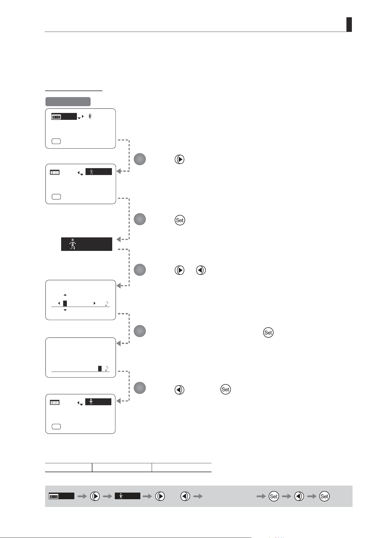
E111
4. Operation in Full Mode
[]
Lock
EnterPassword
EnterPassword
Unlock OK?
y/n
[]
Lock
[ I-Gain ]
[Adj]
[]
MENU
Lock
A
Fr1P
[ Basic ]
[Trk]
OFF
[I-Tq]H
[ I-Gain ]
[Adj]
A
Fr1P
[ Basic ]
[Trk]
OFF
[I-Tq]H
MENU
[]
1
[ I-Gain ]
[Adj]
A
Fr1P
[ Basic ]
[Trk]
OFF
[I-Tq]H
MENU
(2) Unlocking Settings
Settings can be unlocked in two ways, as follows.
(Unlocking Setting 1)
Press .
Press
.
The display starts blinking.
Enter the password and press .
The password you entered to lock settings is the password used to unlock them.
Press or .
Press
and then .
“Lock” changes to the user number.
(The previously locked user number is displayed.)
Options
(D)
Unlock Lock
(D): Default value
MENU
[ ]
Lock
or Entering Passwords
Initial Top Screen
1
2
3
4
5
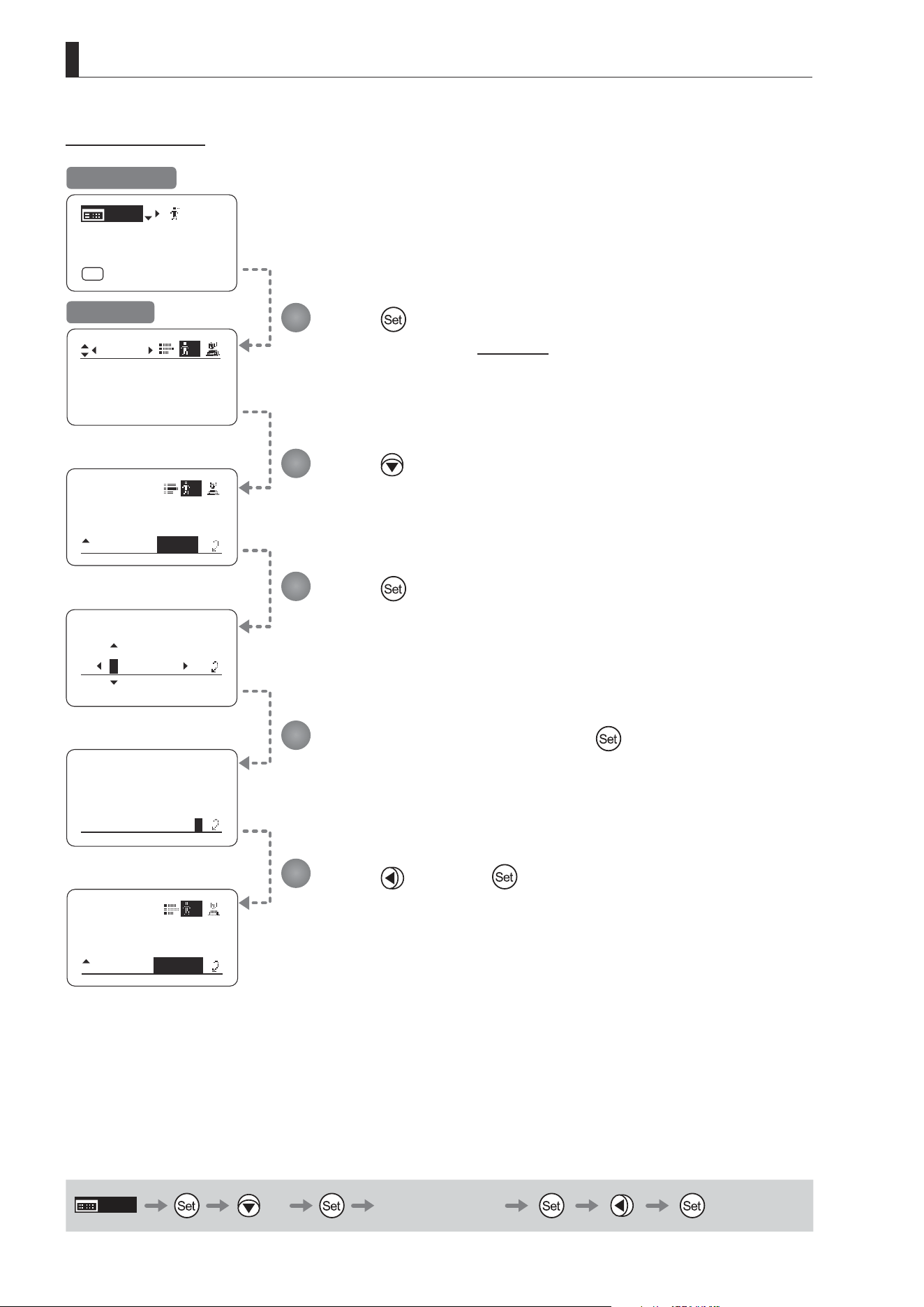
E112
4. Operation in Full Mode
1
1
User
Copy
ToOtherLens
Access:
Lock
EnterPassword
EnterPassword
Unlock OK?
y/n
User
Copy
To OtherLens
Access:
Unlock
Mode:
User
Full
Name:
No.:
1
--------
1
[ I-Gain ]
[Adj]
[]
MENU
Lock
A
Fr1P
[ Basic ]
[Trk]
OFF
[I-Tq]H
(Unlocking Setting 2)
Press .
The display switches to the User screen.
Press seven times.
Enter the password and press
.
The password you entered to lock settings is the password used to unlock them.
Press .
Press
and then .
The settings are now unlocked.
MENU
× 7 Entering Passwords
Initial Top Screen
User Screen
1
2
3
4
5

E113
4. Operation in Full Mode
4.2.2 Switch Screen Settings
The following setting items can be congured on the Switch screen.
Assigning Functions to the AUX Switch
Top
Assigning Functions to the AUX1 Switch
Top
Assigning Functions to the AUX2 Switch
Top
Assigning Functions to the VTR Switch
Top
Assigning Functions to the RET Switch
Top
Specifying Iris A/M Switch
Top
Assigning Functions to the Seesaw
Top
Items labeled
Top
can also be modied from the Top screen.
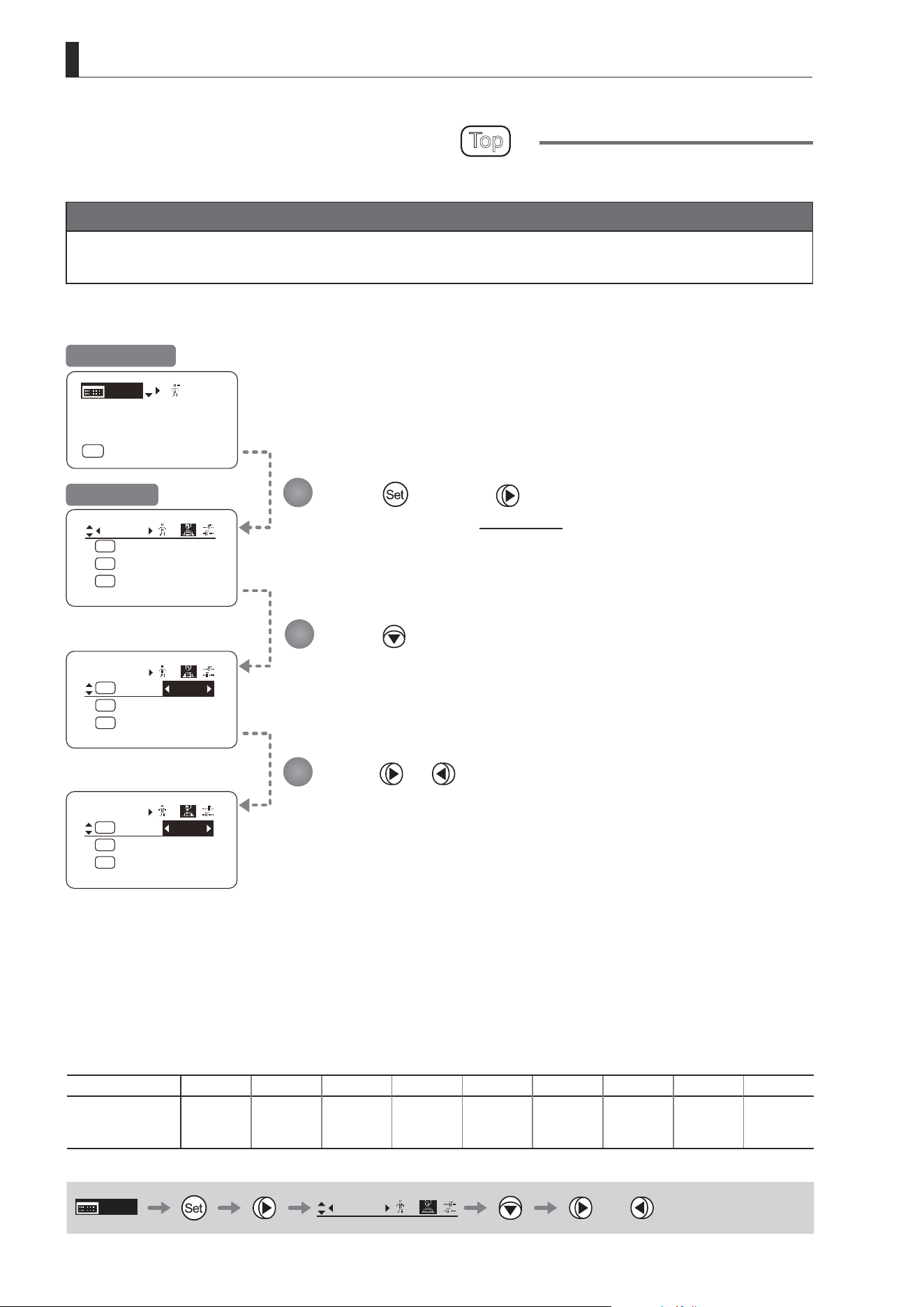
E114
4. Operation in Full Mode
Fr1P
Switch
1
AUX2:
A
A 1
AUX1:
A 2
Fr1P
AUX:
Fr1P
Shtl
Switch
1
AUX2:
A
A 1
AUX1:
A 2
AUX:
Fr1P
Shtl
VTR
Switch
1
AUX2:
A
A 1
AUX1:
A 2
AUX:
Fr1P
Shtl
[ I-Gain ]
[Adj]
[]
MENU
1
A
Fr1P
[ Basic ]
[Trk]
OFF
[I-Tq]H
Press and then .
The display switches to the Switch screen.
Press .
[AUX] is underlined.
The previous or default function is highlighted.
Press or .
Press left or right until you reach the desired function.
Assigning Functions to the AUX Switch
Top
The AUX switch can be programmed to activate a function of your choice.
Important
First, switch to the user for whom the settings apply.
(For instructions, see “4.1.3 Switching Users” or “4.2.1 User Screen Settings: Switching Users.”)
Initial Top Screen
Switch Screen
Options
(D)
Fr1P Fr1F Fr2P Fr2F Sped Shtl NON VTR RET
Description
Framing Preset1
switch
(preset speed)
Framing Preset1
switch
(max. speed)
Framing Preset2
switch
(preset speed)
Framing Preset2
switch
(max. speed)
Speed Preset
switch
Shuttle-Shot
switch
No function VTR switch RET switch
(D): Default value
MENU
Switch
1
or
1
2
3
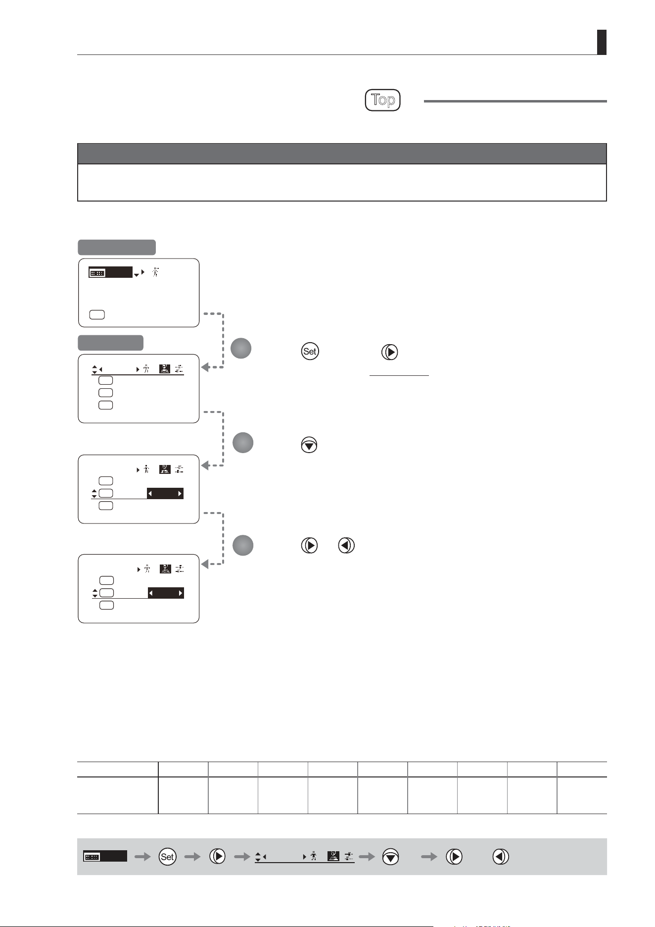
E115
4. Operation in Full Mode
Switch
1
AUX2:
A
A 1
AUX1:
A 2
Fr1P
AUX:
Fr1P
Shtl
Switch
1
AUX2:
A
A 1
AUX1:
A 2
AUX:
Fr1P
Shtl
Fr1P
Switch
1
AUX2:
A
A 1
AUX1:
A 2
AUX:
Fr1P
VTR
Fr1P
[ I-Gain ]
[Adj]
[]
MENU
1
A
Fr1P
[ Basic ]
[Trk]
OFF
[I-Tq]H
Assigning Functions to the AUX1 Switch
Top
The AUX1 switch can be programmed to activate a function of your choice.
Important
First, switch to the user for whom the settings apply.
(For instructions, see “4.1.3 Switching Users” or “4.2.1 User Screen Settings: Switching Users.”)
Press and then .
The display switches to the Switch screen.
Press twice.
[AUX1] is underlined.
The previous or default function is highlighted.
Press or .
Press left or right until you reach the desired function.
Initial Top Screen
Switch Screen
Options Fr1P Fr1F Fr2P Fr2F Sped
(D)
Shtl NON VTR RET
Description
Framing Preset1
switch
(preset speed)
Framing Preset1
switch
(max. speed)
Framing Preset2
switch
(preset speed)
Framing Preset2
switch
(max. speed)
Speed Preset
switch
Shuttle-Shot
switch
No function VTR switch RET switch
(D): Default value
MENU
Switch
1
× 2 or
1
2
3
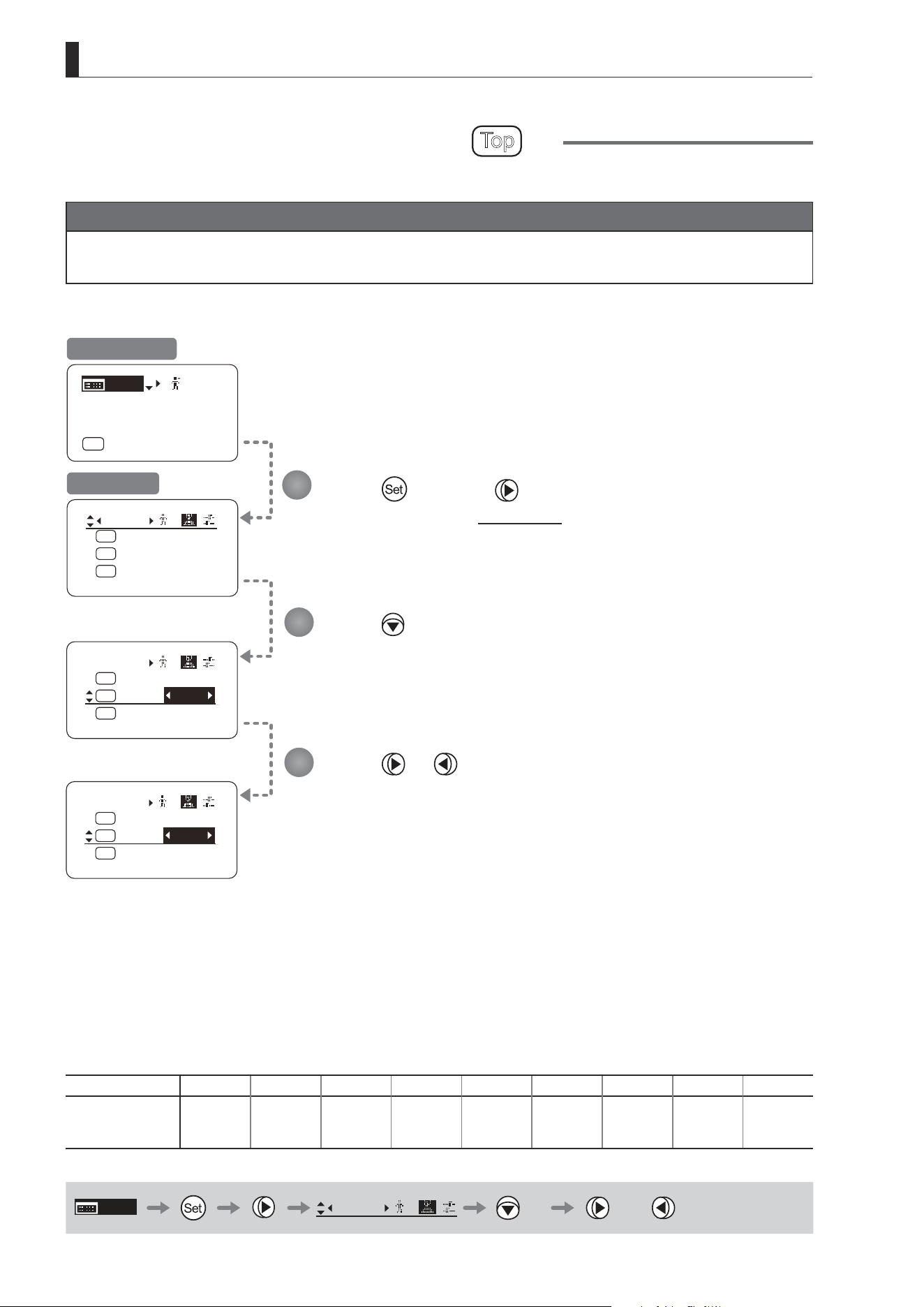
E116
4. Operation in Full Mode
Switch
1
AUX2:
A
A 1
AUX1:
A 2
Fr1P
AUX:
Fr1P
Shtl
[ I-Gain ]
[Adj]
[]
MENU
1
A
Fr1P
[ Basic ]
[Trk]
OFF
[I-Tq]H
Switch
1
VTR:
A1
A 2
AUX2:
V
AUX1:
VTR
Fr1P
Shtl
Switch
1
VTR:
A1
A 2
AUX2:
V
AUX1:
VTR
Sped
Shtl
Assigning Functions to the AUX2 Switch
Top
The AUX2 switch can be programmed to activate a function of your choice.
Important
First, switch to the user for whom the settings apply.
(For instructions, see “4.1.3 Switching Users” or “4.2.1 User Screen Settings: Switching Users.”)
Press and then .
The display switches to the Switch screen.
Press three times.
[AUX2] is underlined.
The previous or default function is highlighted.
Press or .
Press left or right until you reach the desired function.
Initial Top Screen
Switch Screen
Options
(D)
Fr1P Fr1F Fr2P Fr2F Sped Shtl NON VTR RET
Description
Framing Preset1
switch
(preset speed)
Framing Preset1
switch
(max. speed)
Framing Preset2
switch
(preset speed)
Framing Preset2
switch
(max. speed)
Speed Preset
switch
Shuttle-Shot
switch
No function VTR switch RET switch
(D): Default value
MENU
Switch
1
× 3 or
1
2
3
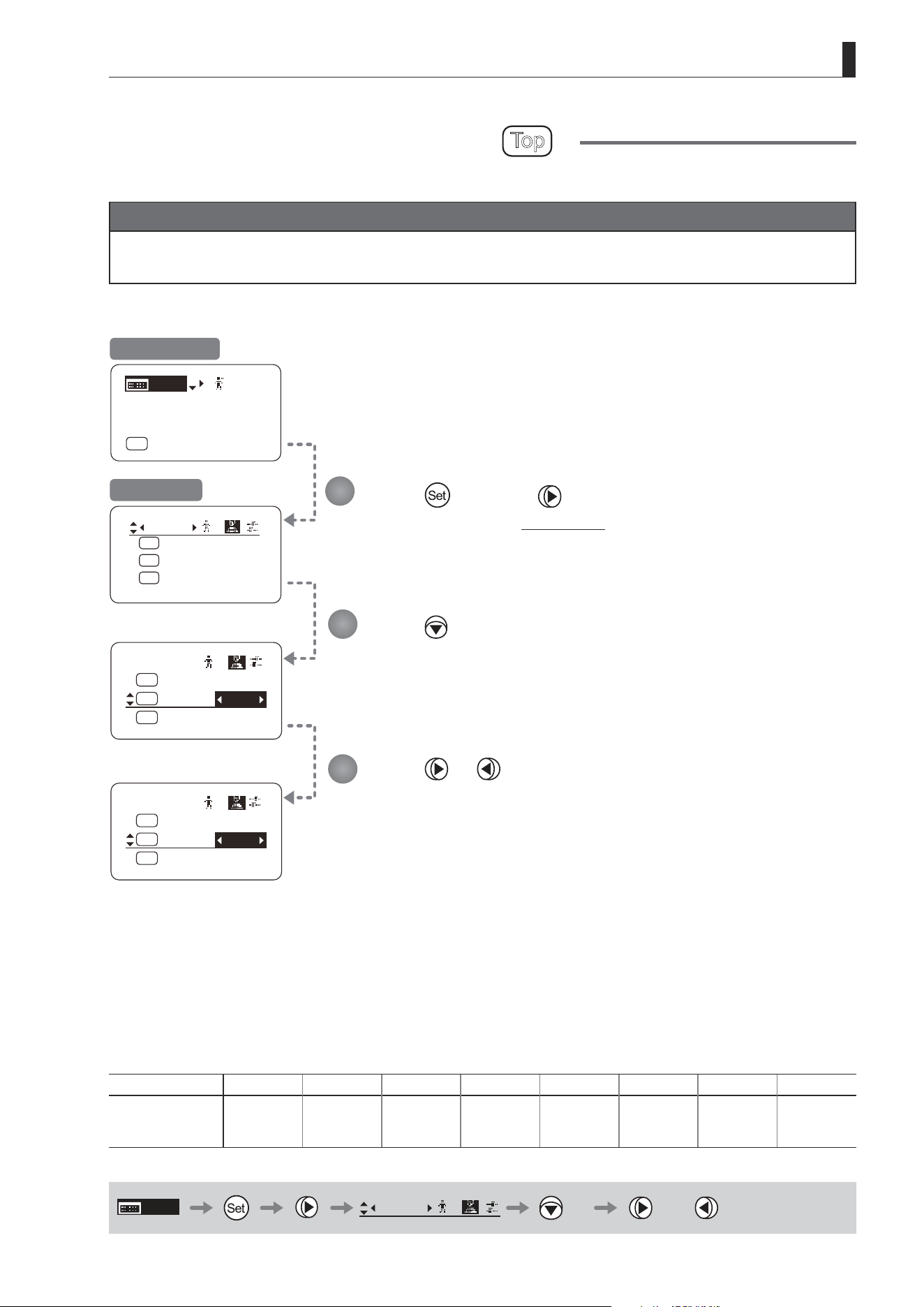
E117
4. Operation in Full Mode
Switch
1
AUX2:
A
A 1
AUX1:
A 2
Fr1P
AUX:
Fr1P
Shtl
Switch
1
RET:
R
RET
AUX2:
A 2
VTR:
V
Fr1P
VTR
Switch
1
RET:
R
RET
AUX2:
A 2
VTR:
V
Fr1P
RET
[ I-Gain ]
[Adj]
[]
MENU
1
A
Fr1P
[ Basic ]
[Trk]
OFF
[I-Tq]H
Assigning Functions to the VTR Switch
Top
The VTR switch can be programmed to activate a function of your choice.
Important
First, switch to the user for whom the settings apply.
(For instructions, see “4.1.3 Switching Users” or “4.2.1 User Screen Settings: Switching Users.”)
Press and then .
The display switches to the Switch screen.
Press four times.
[VTR] is underlined.
The previous or default function is highlighted.
Press or .
Press left or right until you reach the desired function.
Initial Top Screen
Switch Screen
Options Fr1P Fr1F Fr2P Fr2F Sped Shtl
(D)
VTR RET
Description
Framing Preset1
switch
(preset speed)
Framing Preset1
switch
(max. speed)
Framing Preset2
switch
(preset speed)
Framing Preset2
switch
(max. speed)
Speed Preset
switch
Shuttle-Shot
switch
VTR switch RET switch
(D): Default value
MENU
Switch
1
× 4 or
1
2
3
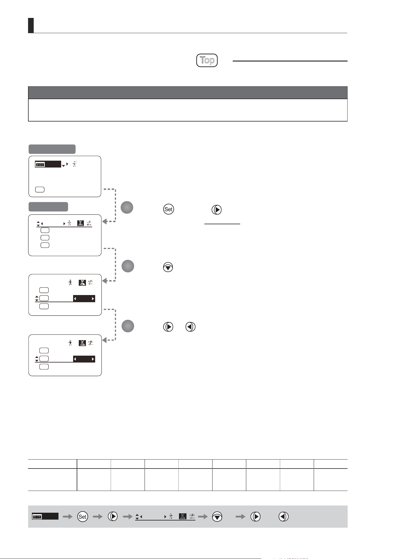
E118
4. Operation in Full Mode
Switch
1
A/M:
AM
Norm
VTR:
V
RET:
R
VTR
RET
Switch
1
A/M:
AM
Norm
VTR:
V
RET:
R
VTR
Sped
Switch
1
AUX2:
A
A 1
AUX1:
A 2
Fr1P
AUX:
Fr1P
Shtl
[ I-Gain ]
[Adj]
[]
MENU
1
A
Fr1P
[ Basic ]
[Trk]
OFF
[I-Tq]H
Assigning Functions to the RET Switch
Top
The RET switch can be programmed to activate a function of your choice.
Important
First, switch to the user for whom the settings apply.
(For instructions, see “4.1.3 Switching Users” or “4.2.1 User Screen Settings: Switching Users.”)
Press and then .
The display switches to the Switch screen.
Press ve times.
[RET] is underlined.
The previous or default function is highlighted.
Press or .
Press left or right until you reach the desired function.
Initial Top Screen
Switch Screen
Options Fr1P Fr1F Fr2P Fr2F Sped Shtl VTR
(D)
RET
Description
Framing Preset1
switch
(preset speed)
Framing Preset1
switch
(max. speed)
Framing Preset2
switch
(preset speed)
Framing Preset2
switch
(max. speed)
Speed Preset
switch
Shuttle-Shot
switch
VTR switch RET switch
(D): Default value
MENU
Switch
1
× 5 or
1
2
3
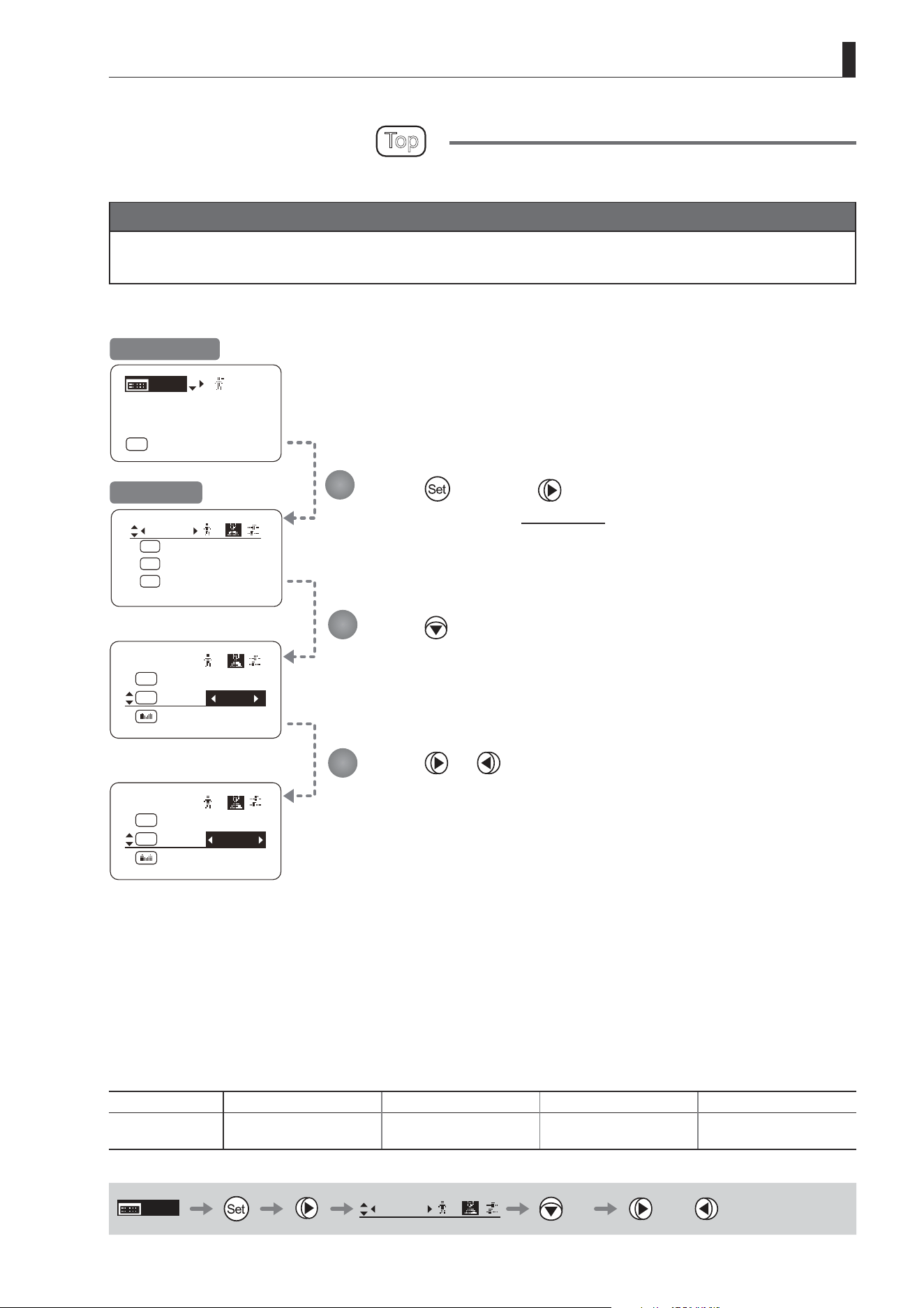
E119
4. Operation in Full Mode
Switch
1
AUX2:
A
A 1
AUX1:
A 2
Fr1P
AUX:
Fr1P
Shtl
Switch
1
SSaw:
A/M:
AM
RET:
R
RET
Zoom
Norm
Switch
1
SSaw:
A/M:
AM
RET:
R
RET
Zoom
Reve
[ I-Gain ]
[Adj]
[]
MENU
1
A
Fr1P
[ Basic ]
[Trk]
OFF
[I-Tq]H
Specifying Iris A/M Switch
Top
The Iris A/M switch can be programmed to activate a function of your choice.
Important
First, switch to the user for whom the settings apply.
(For instructions, see “4.1.3 Switching Users” or “4.2.1 User Screen Settings: Switching Users.”)
Press and then .
The display switches to the Switch screen.
Press six times.
[A/M] is underlined.
The previous or default function is highlighted.
Press or .
Press left or right until you reach the desired function.
Initial Top Screen
Switch Screen
Options
(D)
Norm Reve Auto Manu
Description
Normal operation
A: Auto / M: Manual
Reverse operation
A: Manual / M: Auto
Auto Only
A: Auto / M: Auto
Manual Only
A: Manual / M: Manual
(D): Default value
MENU
Switch
1
× 6 or
1
2
3
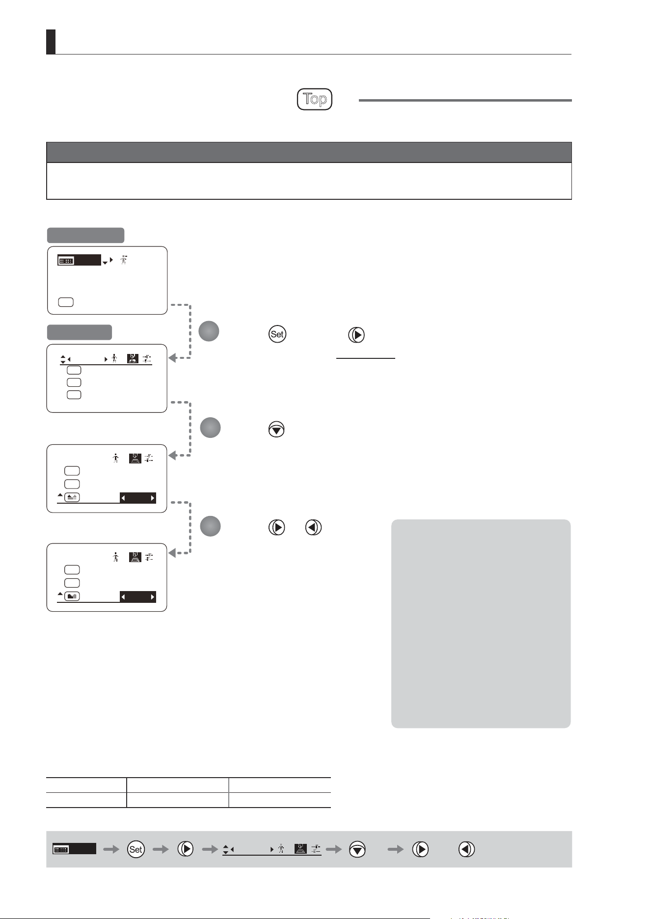
E120
4. Operation in Full Mode
Switch
1
SSaw:
A/M:
AM
RET:
R
RET
Norm
Zoom
Switch
1
SSaw:
A/M:
AM
RET:
R
RET
Norm
Iris
[ I-Gain ]
[Adj]
[]
MENU
1
A
Fr1P
[ Basic ]
[Trk]
OFF
[I-Tq]H
Switch
1
AUX2:
A
A 1
AUX1:
A 2
Fr1P
AUX:
Fr1P
Shtl
Assigning Functions to the Seesaw
Top
The zoom seesaw switch can be programmed to control either the {Zoom} or {Iris}.
Important
First, switch to the user for whom the settings apply.
(For instructions, see “4.1.3 Switching Users” or “4.2.1 User Screen Settings: Switching Users.”)
Press and then .
The display switches to the Switch screen.
Press seven times.
[SSaw] is underlined.
The previous or default function is highlighted.
Press or .
Press left or right until you reach
the desired function.
Initial Top Screen
Switch Screen
Options
(D)
Zoom Iris
Description Zoom operation Iris operation
(D): Default value
MENU
Switch
1
× 7 or
1
2
3
Note: Note on Iris Assignment
1. The seesaw switch will no longer
control zooming.
2. To control the iris with the rocker
switch, you must set the iris mode
to manual.
Operation is not possible in Auto or
Remote mode.
3. Press the Telephoto side to open
the iris, or press the Wide end side
to close it.
4. Zoom speed control adjustments
also apply to iris control, and you
can specify the maximum iris
speed. (See “4.2.5 Zoom Screen
Settings: Specifying Maximum
Zoom Speed Control.”)

E121
4. Operation in Full Mode
4.2.3 Preset Screen Settings
The following setting items can be congured on the Preset screen.
Switching What Frame Preset 1 Controls
Switching What Frame Preset 2 Controls
Specifying the Preset Mode Zoom Speed
Specifying Zoom Start Responsiveness for Presets
Specifying Zoom Stop Responsiveness for Presets
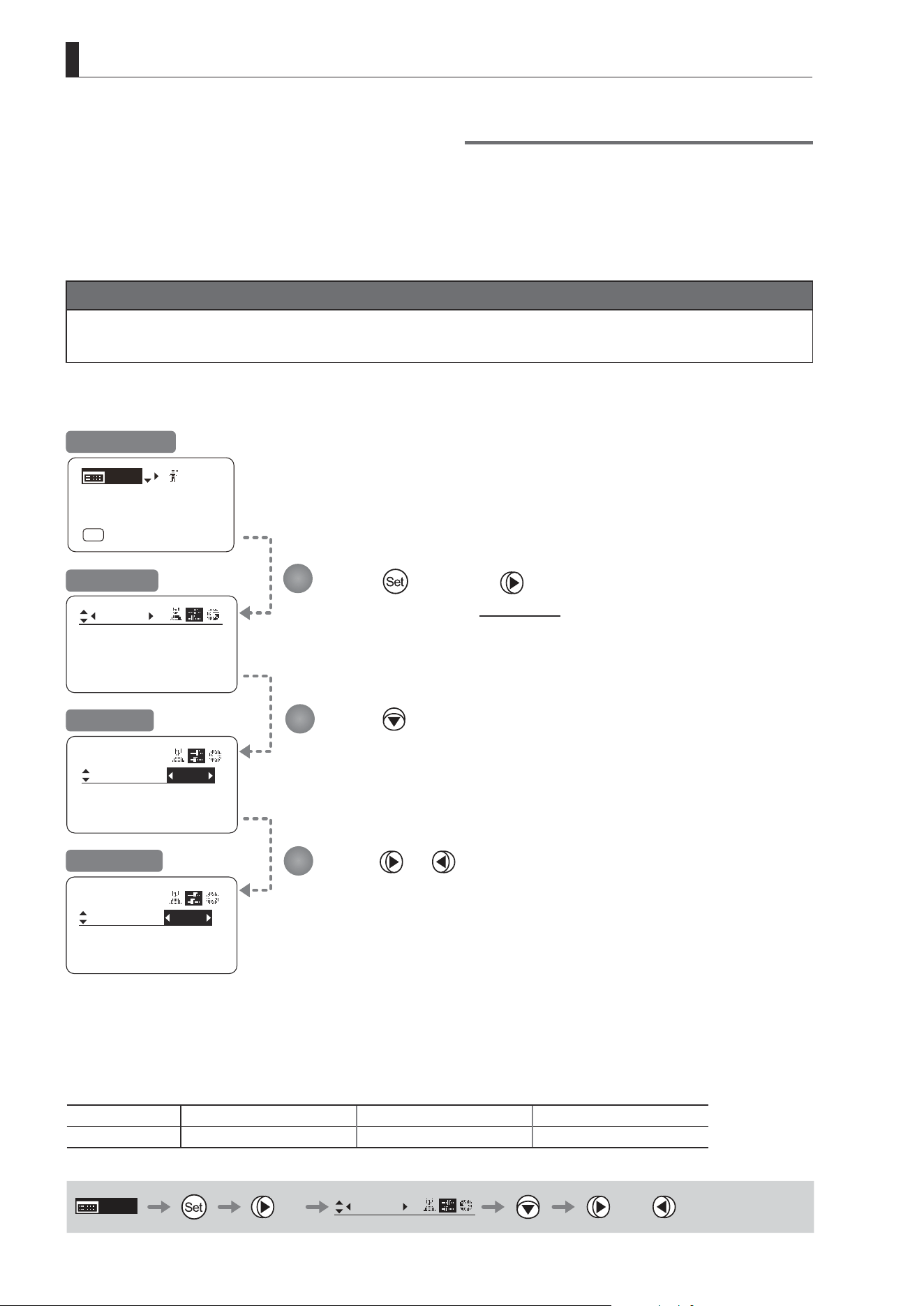
E122
4. Operation in Full Mode
Frame1:
Preset
Zoom
Frame2: Zoom
ZSpeed: 800
Frame1:
Preset
Frame2: Zoom
ZSpeed: 800
Frame1:
Preset
Frame2: Zoom
ZSpeed: 800
Zoom
Focus
[ I-Gain ]
[Adj]
[]
MENU
1
A
Fr1P
[ Basic ]
[Trk]
OFF
[I-Tq]H
Press once and twice.
The display switches to the Preset screen.
Press .
[Frame1] is underlined.
The previous or default value is highlighted.
Press or .
Switching What Frame Preset 1 Controls
Switch what frame preset 1 controls, as needed.
Zoom : Move the zoom position to the position in memory
Focus : Move the focus position to the position in memory
Z+F : Move the zoom and focus position to the position in memory
Important
First, switch to the user for whom the settings apply.
(For instructions, see “4.1.3 Switching Users” or “4.2.1 User Screen Settings: Switching Users.”)
Initial Top Screen
Preset Screen
Screen A
Frame1 Screen
Options
(D)
Zoom Focus Z+F
Description Control zooming Control focusing Control zooming and focusing
(D): Default value
MENU
× 2
Preset
or
1
2
3
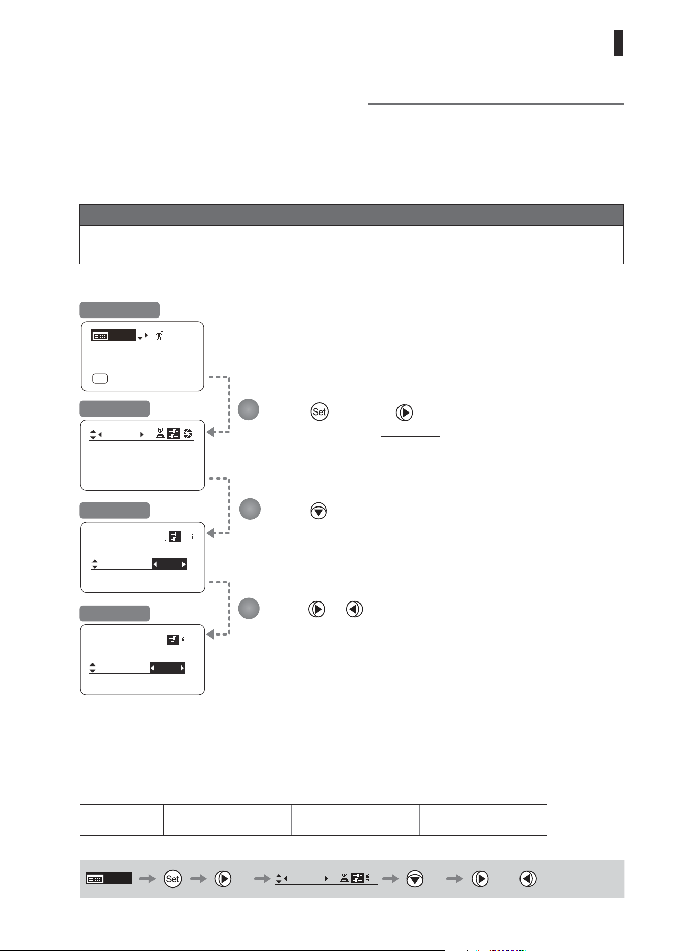
E123
4. Operation in Full Mode
Frame1:
Preset
Zoom
Frame2: Zoom
ZSpeed: 800
Frame1:
Preset
Frame2:
Zoom
ZSpeed: 800
Frame1:
Preset
Frame2:
Zoom
ZSpeed: 800
Zoom
Focus
[ I-Gain ]
[Adj]
[]
MENU
1
A
Fr1P
[ Basic ]
[Trk]
OFF
[I-Tq]H
Press once and twice.
The display switches to the Preset screen.
Press twice.
[Frame2] is underlined.
The previous or default value is highlighted.
Press or .
Switching What Frame Preset 2 Controls
Switch what frame preset 2 controls, as needed.
Zoom : Move the zoom position to the position in memory
Focus : Move the focus position to the position in memory
Z+F : Move the zoom and focus position to the position in memory
Important
First, switch to the user for whom the settings apply.
(For instructions, see “4.1.3 Switching Users” or “4.2.1 User Screen Settings: Switching Users.”)
Initial Top Screen
Preset Screen
Screen A
Frame2 Screen
Options
(D)
Zoom Focus Z+F
Description Control zooming Control focusing Control zooming and focusing
(D): Default value
MENU
× 2
Preset
× 2 or
1
2
3
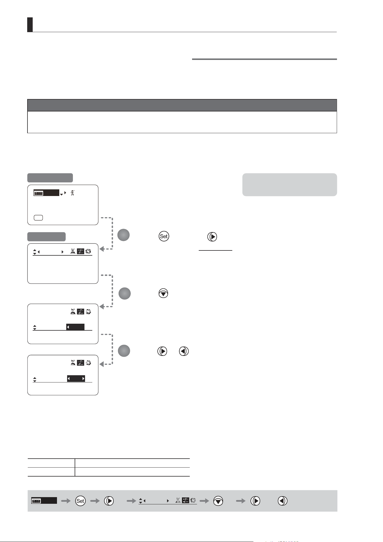
E124
4. Operation in Full Mode
Frame1:
Preset
Zoom
Frame2: Zoom
ZSpeed: 800
Frame2:
Preset
Zoom
ZMovement
ZSpeed:
800
500
Frame2:
Preset
Zoom
ZMovement
ZSpeed:
[ I-Gain ]
[Adj]
[]
MENU
1
A
Fr1P
[ Basic ]
[Trk]
OFF
[I-Tq]H
Press once and twice.
The display switches to the Preset screen.
Press three times.
[ZSpeed] is underlined.
The previous or default value is highlighted.
Press or .
Press left or right until you reach the desired value.
Specifying the Preset Mode Zoom Speed
Congure the zoom speed from any position to the position in memory, as needed.
To adjust the value, use either the Memo button (refer to the operation manual "Lens") or display operations.
Regardless of the method of adjustment used, the most recent setting takes precedence.
Important
First, switch to the user for whom the settings apply.
(For instructions, see “4.1.3 Switching Users” or “4.2.1 User Screen Settings: Switching Users.”)
Initial Top Screen
Preset Screen
Note: Your specied values apply to
both Fr1P and Fr2P.
Options 1 to
(D)
800
Description Slowest Fastest
(D): Default value
MENU
× 2
Preset
× 3 or
1
2
3
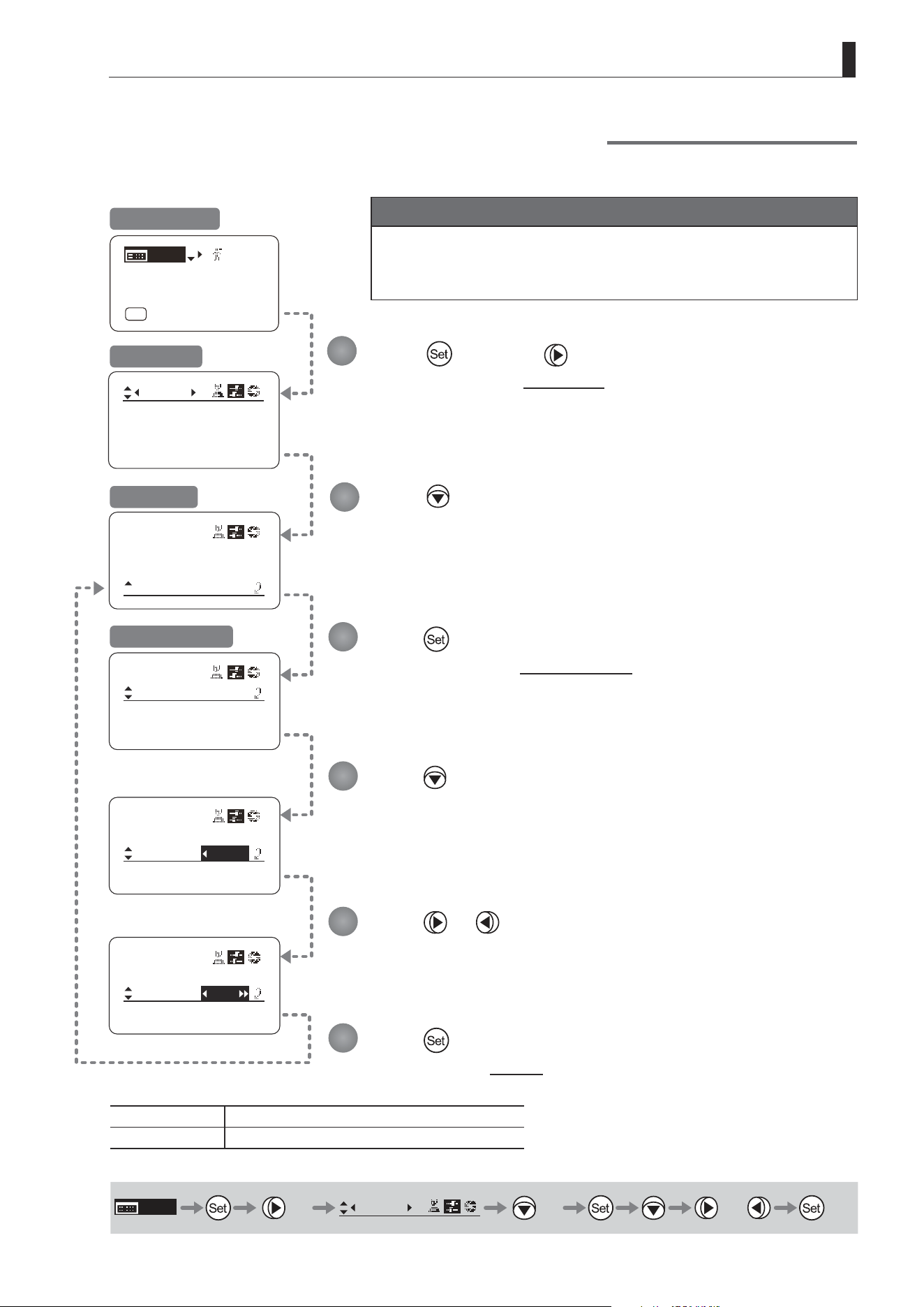
E125
4. Operation in Full Mode
Frame2:
Preset
Zoom
ZSpeed:
ZMovement
800
Preset
ZMovement
Stop:
Start:
99
91
Preset
ZMovement
Stop:
Start:
D99
91
Preset
ZMovement
Stop:
Start:
50
91
Frame1:
Preset
Zoom
Frame2: Zoom
ZSpeed: 800
[ I-Gain ]
[Adj]
[]
MENU
1
A
Fr1P
[ Basic ]
[Trk]
OFF
[I-Tq]H
Press once and twice.
The display switches to the Preset screen.
Press four times.
[ZMovement] is underlined.
Press .
The display switches to the ZMovement screen.
Press .
[Start] is underlined.
The previous or default value is highlighted.
Press or .
Press left or right until you reach the desired value.
Press .
The display reverts to Screen A.
Specifying Zoom Start Responsiveness for Presets
Specify initial responsiveness in zooming for preset operations.
Initial Top Screen
Preset Screen
Screen A
ZMovement Screen
Options 00 to
(D)
99
Description Start gradually Start quickly
(D): Default value
MENU
× 2
Preset
× 4 or
1
2
3
4
5
6
Important
First, switch to the user for whom the settings apply.
(For instructions, see “4.1.3 Switching Users” or “4.2.1 User Screen
Settings: Switching Users.”)
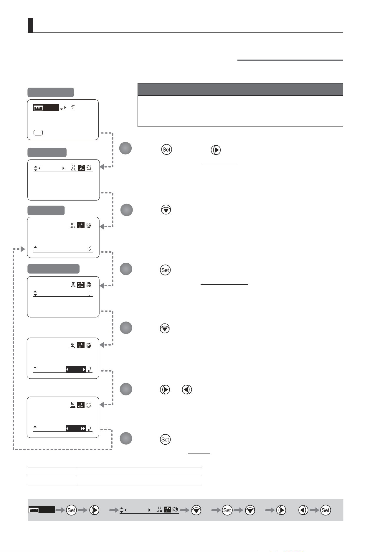
E126
4. Operation in Full Mode
Frame2:
Preset
Zoom
ZSpeed:
ZMovement
800
Preset
ZMovement
Stop:
Start:
99
91
Preset
ZMovement
Stop:
Start:
99
D91
Preset
ZMovement
Stop:
Start:
99
70
Frame1:
Preset
Zoom
Frame2: Zoom
ZSpeed: 800
[ I-Gain ]
[Adj]
[]
MENU
1
A
Fr1P
[ Basic ]
[Trk]
OFF
[I-Tq]H
Press once and twice.
The display switches to the Preset screen.
Press four times.
[ZMovement] is underlined.
Press .
The display switches to the ZMovement screen.
Press twice.
[Stop] is underlined.
The previous or default value is highlighted.
Press or .
Press left or right until you reach the desired value.
Press .
The display reverts to Screen A.
Specifying Zoom Stop Responsiveness for Presets
Specify nal responsiveness in zooming for preset operations.
Initial Top Screen
Preset Screen
Screen A
ZMovement Screen
Options 00 to 99
Description Stop gradually Stop quickly
Default value: 91
MENU
× 2
Preset
× 4
× 2 or
1
2
3
4
5
6
Important
First, switch to the user for whom the settings apply.
(For instructions, see “4.1.3 Switching Users” or “4.2.1 User Screen
Settings: Switching Users.”)

E127
4. Operation in Full Mode
4.2.4 Iris Screen Settings
The following setting items can be congured on the Iris screen.
Specifying Iris Gain
(1) Specifying Auto Iris Gain
Top
(2) Specifying Remote Iris Gain
Top
Specifying Iris Torque
Top
Iris Compensation ON/OFF
Iris Close Detection ON/OFF
Focus Demand Iris Control ON/OFF
Items labeled
Top
can also be modied from the Top screen.
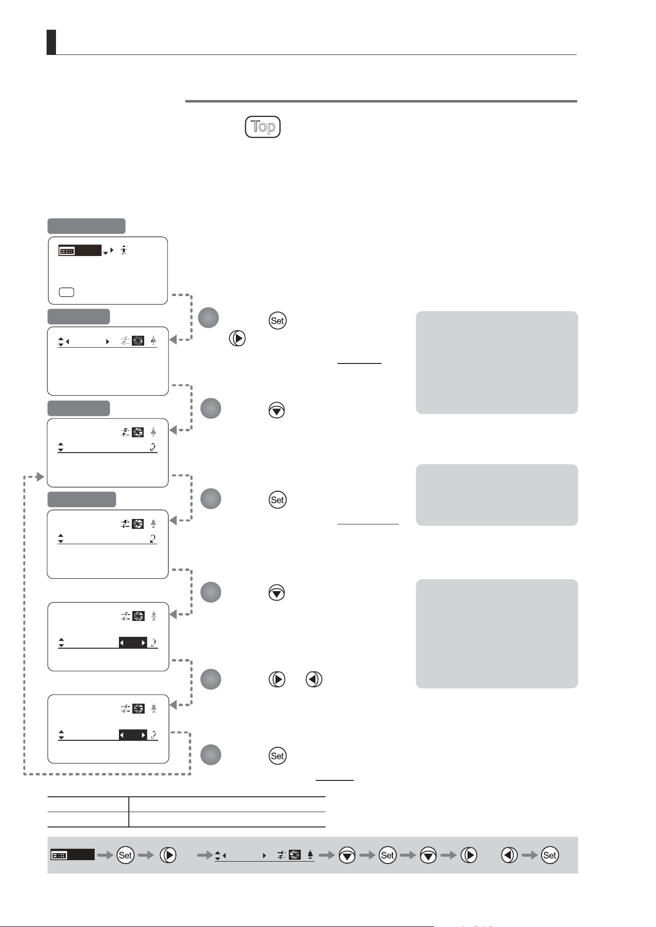
E128
4. Operation in Full Mode
[ I-Gain ]
Iris
Remote:
90
Auto:
50
[]
[ I-Gain ]
Iris
Remote:
90
Auto:
55
[]
Iris
[]
[ I-Gain ]
Torque: High
Comp: ON
[ I-Gain ]
Iris
Remote:
90
Auto:
50
[]
[ I-Gain ]
Iris
Comp: ON
Torque: High
[]
[ I-Gain ]
[Adj]
[]
MENU
1
A
Fr1P
[ Basic ]
[Trk]
OFF
[I-Tq]H
Specifying Iris Gain
(1) Specifying Auto Iris Gain
Top
Although this value is factory-set, it can be adjusted as needed.
To adjust the value, use either the auto iris gain adjustment trimmer (refer to the operation manual
"Lens"
) or display operations.
Regardless of the method of adjustment used, the most recent setting takes precedence.
The same auto iris gain value applies to all users, regardless of the current user. Thus, there is no need to switch users in
advance. Unlike most other setting adjustments, any changes to this setting also apply to user 0.
Note: Do the following when
adjusting gain while checking
iris operation.
→ Conrm that the drive unit A/M
switch is set to [Auto] mode.
→ Set the camera iris mode to
[Auto].
Note: As you look at the lens iris
ring, set it to the position of
maximum gain at which “focus
hunting” does not occur.
Note: The current iris gain value
is retained even if you reset
other settings as described in
“4.2.1 Resetting Values.” For
this reason, you will no longer
be able to view the default
setting. If necessary, make
a note of the default setting
before adjusting this value.
Press once and
three times.
The display switches to the Iris screen.
Press .
[I-Gain] is underlined.
Press .
The display switches to the [I-Gain] screen.
Press .
The display reverts to Screen A.
Press .
[Auto] is underlined.
The previous or default value is
highlighted.
Press or .
Press left or right until you reach the desired function.
Initial Top Screen
Iris Screen
Screen A
[I-Gain] Screen
Options 01 to 99
Default: Varies depending on the factory-set value, but corresponds to
the value determined with the iris gain adjustment trimmer.
Description Minimum gain Maximum gain
MENU
× 3
Iris
[ ]
or
1
2
3
4
5
6
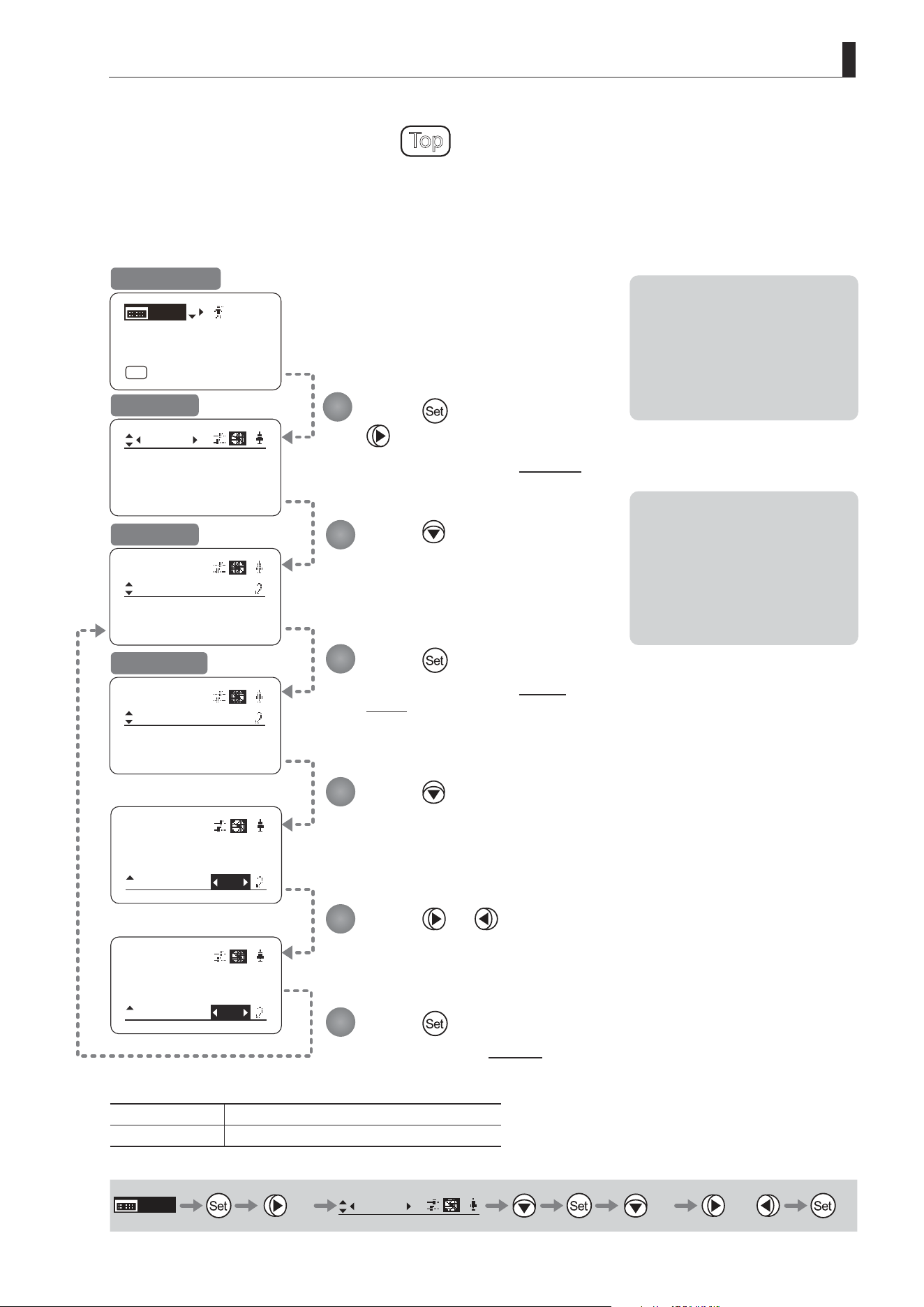
E129
4. Operation in Full Mode
52
[ I-Gain ]
Iris
Remote:
90
Auto:
50
[]
[ I-Gain ]
Iris
Remote:
93
Auto:
50
[]
Iris
[]
[ I-Gain ]
Torque: High
Comp: ON
[ I-Gain ]
Iris
Remote:
90
Auto:
50
[]
[ I-Gain ]
Iris
Comp: ON
Torque: High
[]
[ I-Gain ]
[Adj]
[]
MENU
1
A
Fr1P
[ Basic ]
[Trk]
OFF
[I-Tq]H
(2) Specifying Remote Iris Gain
Top
Although this value is factory-set, it can be adjusted as needed.
The same remote iris gain value applies to all users, regardless of the current user. Thus, there is no need to switch
users in advance. Unlike most other setting adjustments, any changes to this setting also apply to user 0.
Note: Do the following when
adjusting gain while checking
iris operation.
→ Conrm that the drive unit A/M
switch is set to [Auto] mode.
→ Set the camera iris mode to
[Remote].
Note: The current iris gain value
is retained even if you reset
other settings as described in
“4.2.1 Resetting Values.” For
this reason, you will no longer
be able to view the default
setting. If necessary, make
a note of the default setting
before adjusting this value.
Press once and
three times.
The display switches to the Iris screen.
Press .
[I-Gain] is underlined.
Press .
The display switches to the [I-Gain]
screen.
Press .
The display reverts to Screen A.
Press twice.
[Remote] is underlined.
The previous or default value is highlighted.
Press or .
Press left or right until you reach the desired function.
Initial Top Screen
Iris Screen
Screen A
[I-Gain] Screen
Options 01 to 99
Description Minimum gain Maximum gain
Default value: 90
MENU
× 3
Iris
[ ]
× 2
or
1
2
3
4
5
6
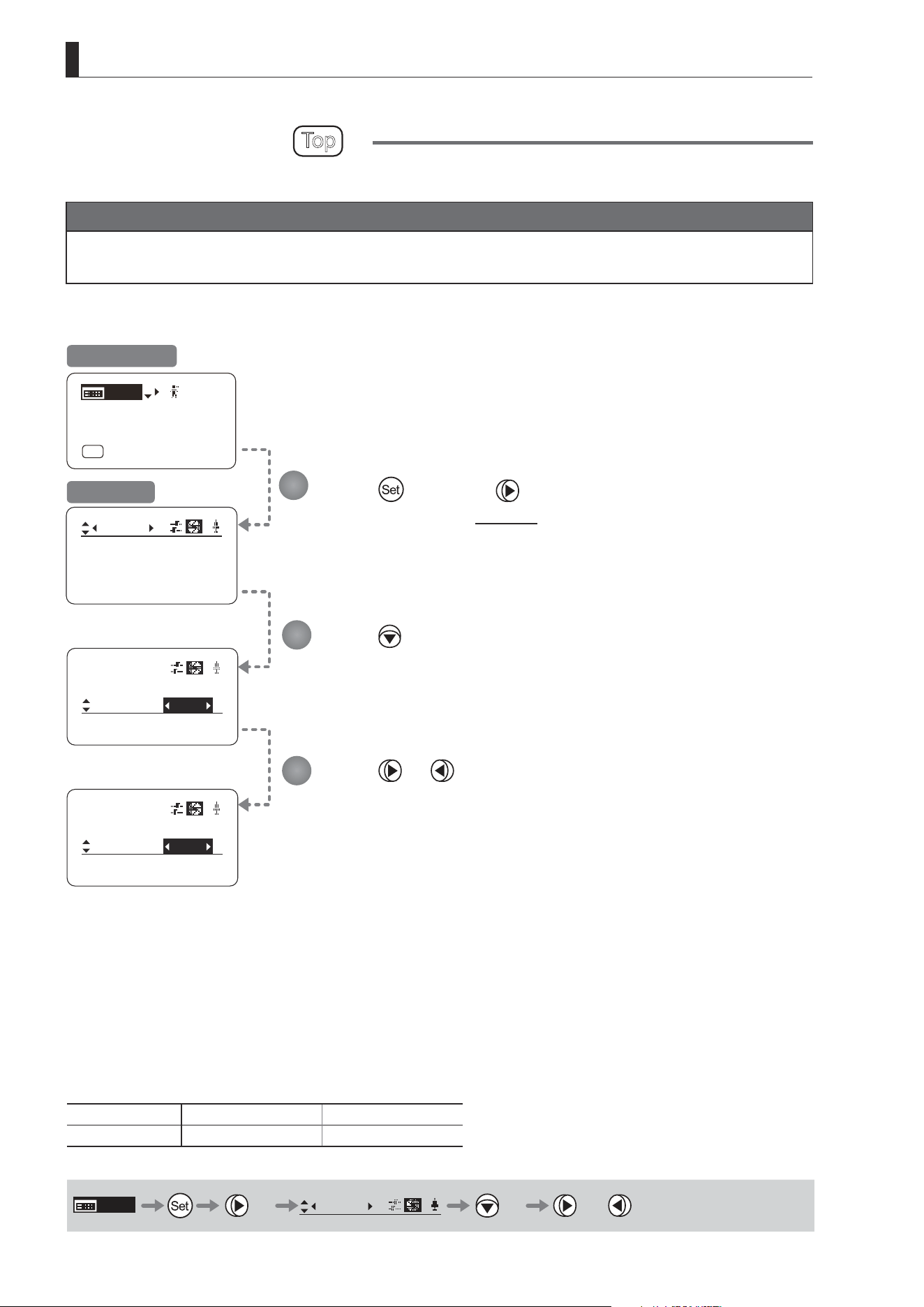
E130
4. Operation in Full Mode
[ I-Gain ]
Iris
[]
Torque:
Comp: ON
High
[ I-Gain ]
Iris
[]
Torque:
Comp: ON
Low
Iris
[]
[ I-Gain ]
Torque: High
Comp: ON
[ I-Gain ]
[Adj]
[]
MENU
1
A
Fr1P
[ Basic ]
[Trk]
OFF
[I-Tq]H
Specifying Iris Torque
Top
Specify the desired level of torque in manual control of the iris ring.
Important
First, switch to the user for whom the settings apply.
(For instructions, see “4.1.3 Switching Users” or “4.2.1 User Screen Settings: Switching Users.”)
Press once and three times.
The display switches to the Iris screen.
Press twice.
[Torque] is underlined.
The previous or default function is highlighted.
Press or .
Press left or right to switch the function to {High} or {Low}.
Initial Top Screen
Iris Screen
Options
(D)
High Low
Description High torque Low torque
(D): Default value
MENU
× 3
Iris
[ ]
× 2 or
1
2
3
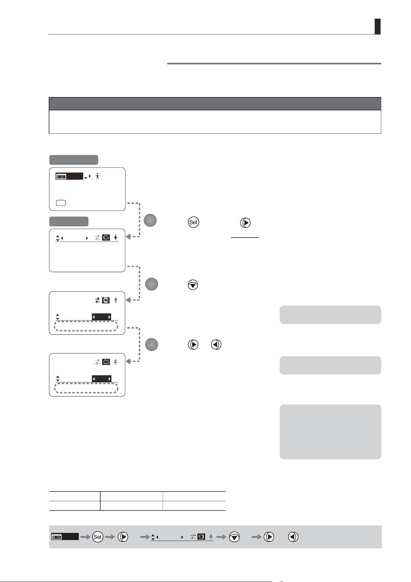
E131
4. Operation in Full Mode
㧖
Iris
[]
[ I-Gain ]
Torque: High
Comp: ON
Iris
[]
Comp:
Close: OFF
Torque: High
ON
[ I-Gain ]
[Adj]
[]
MENU
1
A
Fr1P
[ Basic ]
[Trk]
OFF
[I-Tq]H
Iris
[]
Comp:
Torque: High
OFF
Controller
OFF
㧖
Iris Compensation ON/OFF
The amount of light decreases when an extender (1.5×) is used. Therefore, you can set a function that corrects the iris to
the open side so as to maintain the amount of light.
Important
First, switch to the user for whom the settings apply.
(For instructions, see “4.1.3 Switching Users” or “4.2.1 User Screen Settings: Switching Users.”)
Press once and three times.
The display switches to the Iris screen.
Press three times.
[Comp] is underlined.
The previous or default function is
highlighted.
Press or .
Press left or right to switch the function
{ON} or {OFF}.
Initial Top Screen
Iris Screen
Options
(D)
ON OFF
Description Iris compensation No iris compensation
(D): Default value
MENU
× 3
Iris
[ ]
× 3 or
Note: The iris may not fully close
in some cases when the iris
compensation is set to ON
while an extender (1.5×) is
used. If so, activate detection
as described in “Iris Close
Detection ON/OFF.”
*: Displayed when {Comp} is set to ON.
*: Displayed when {Comp} is set to OFF.
1
2
3
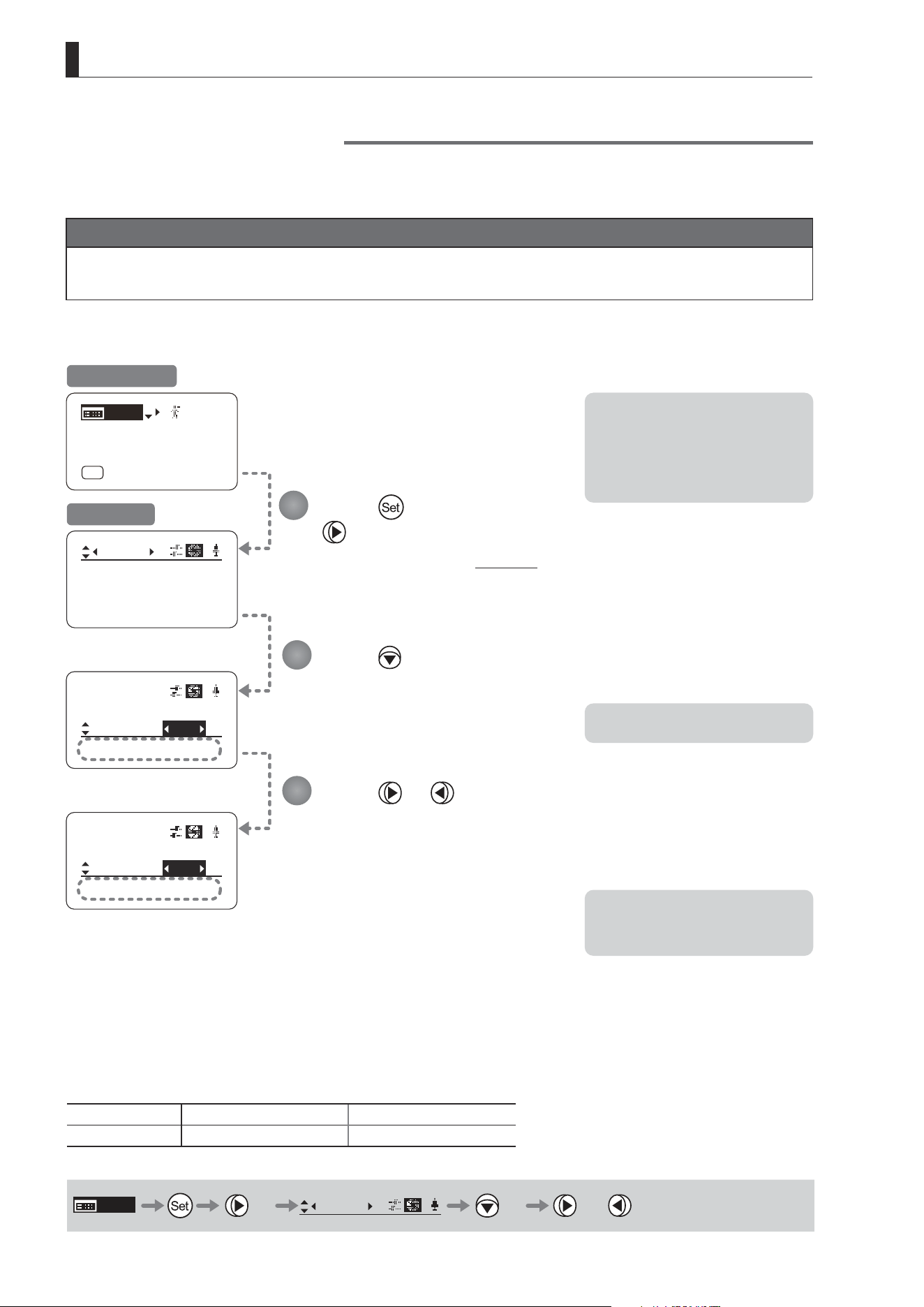
E132
4. Operation in Full Mode
㧖
Iris
[]
[ I-Gain ]
Torque: High
Comp: ON
Iris
[]
Comp:
Close:
ON
Iris
[]
[ I-Gain ]
[Adj]
[]
MENU
1
A
Fr1P
[ Basic ]
[Trk]
OFF
[I-Tq]H
OFF
Controller
OFF
㧖
Comp:
Close:
ON
ON
Controller
OFF
Iris Close Detection ON/OFF
The iris cannot be fully closed when correction is active and an extender (1.5×) is used. As a countermeasure, you can
specify a function to detect iris close and close the iris as needed.
Important
First, switch to the user for whom the settings apply.
(For instructions, see “4.1.3 Switching Users” or “4.2.1 User Screen Settings: Switching Users.”)
Press once and
three times.
The display switches to the Iris screen.
Press four times.
[Close] is underlined.
The previous or default function is
highlighted.
Press or .
Press left or right to switch the function
{ON} or {OFF}.
Initial Top Screen
Iris Screen
Options
(D)
OFF ON
Description No close detection Close detection
(D): Default value
MENU
× 3
Iris
[ ]
× 4 or
Note: With some cameras, iris
compensation may conict
with iris control by the
camera, preventing correct iris
operation. If so, deactivate iris
close detection.
Note: Iris close is detected only
when iris compensation is
enabled.
*: Displayed when {Comp} is set to ON.
1
2
3
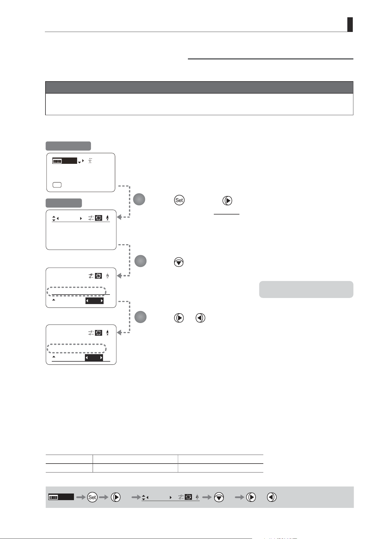
E133
4. Operation in Full Mode
Focus Demand Iris Control ON/OFF
Iris operations using a focus demand can be switched on or o.
Important
First, switch to the user for whom the settings apply.
(For instructions, see “4.1.3 Switching Users” or “4.2.1 User Screen Settings: Switching Users.”)
Press once and three times.
The display switches to the Iris screen.
Press ve times.
[Controller] is underlined.
The previous or default function is
highlighted.
Press or .
Press left or right to switch the function {ON} or {OFF}.
Initial Top Screen
Options ON
(D)
OFF
Description Iris controlled with focus demand Iris not controlled with focus demand
(D): Default value
MENU
× 3
Iris
[ ]
× 5 or
*: Displayed when {Comp} is set to ON.
1
2
3
㧖
Iris
[]
[ I-Gain ]
Torque: High
Comp: ON
Iris
[]
Comp: ON
Close:
[ I-Gain ]
[Adj]
[]
MENU
1
A
Fr1P
[ Basic ]
[Trk]
OFF
[I-Tq]H
Controller:
ON
OFF
㧖
Iris
[]
Comp: ON
Close:
Controller
OFF
OFF
Iris Screen

E134
4. Operation in Full Mode
4.2.5 Zoom Screen Settings
The following setting items can be congured on the Zoom screen.
Zoom Tracking ON/OFF
Top
Specifying Zoom Servo Start Responsiveness
Specifying Zoom Servo Stop Responsiveness
Specifying Zoom Mechanical End Stop Responsiveness
Specifying Seesaw Switch Responsiveness
Top
Specifying Analog Demand Responsiveness
Top
Specifying Maximum Zoom Speed Control
Specifying Minimum Zoom Speed Control
Specifying Servo Type from Zoom Demand
Demand-Based Zoom Speed Adjustment ON/OFF
Specifying Zoom Demand Specications
Items labeled
Top
can also be modied from the Top screen.
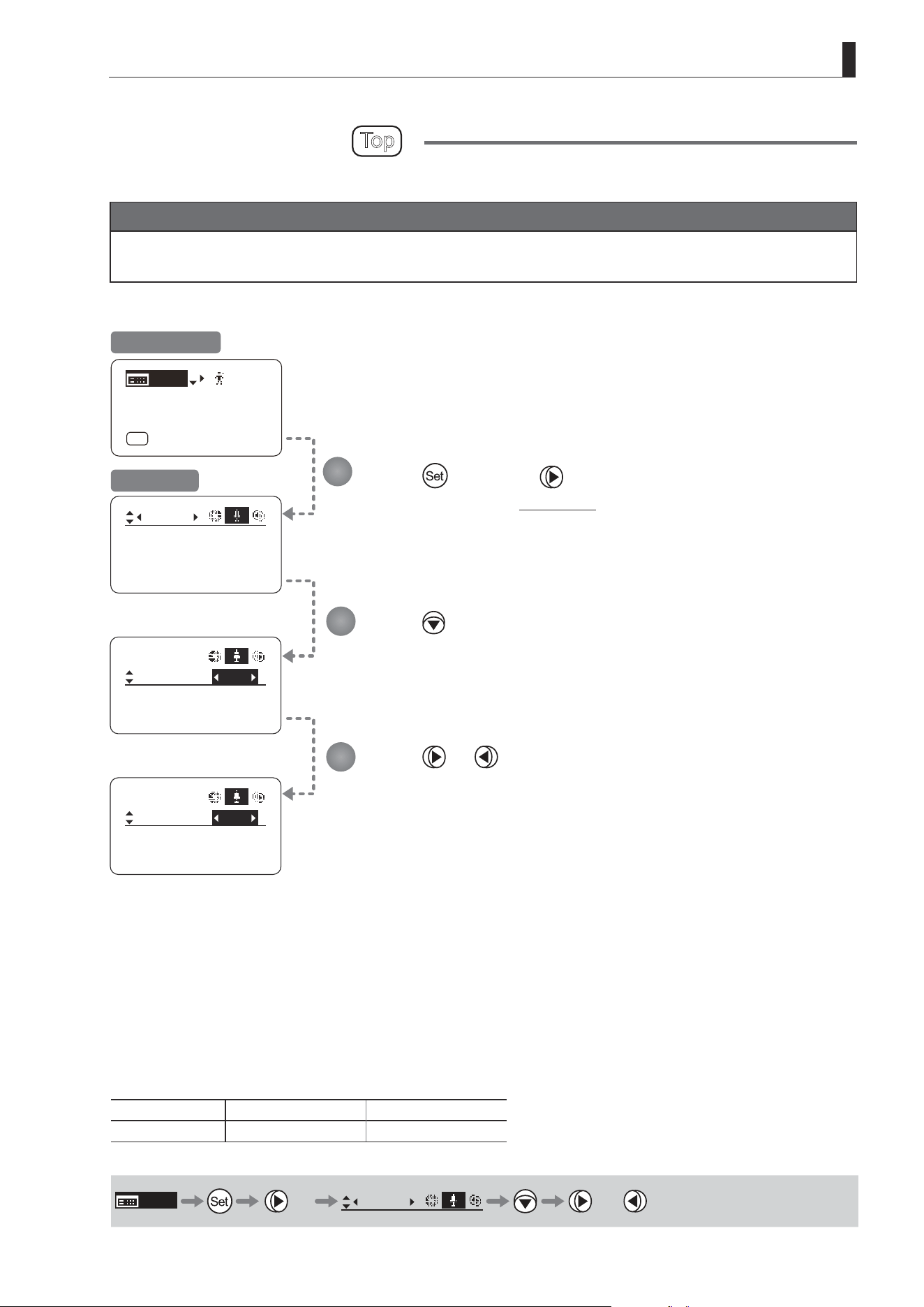
E135
4. Operation in Full Mode
Zoom Tracking ON/OFF
Top
Activate or deactivate zoom tracking as needed.
Important
First, switch to the user for whom the settings apply.
(For instructions, see “4.1.3 Switching Users” or “4.2.1 User Screen Settings: Switching Users.”)
Tracking: OFF
Movement
Zoom
[]
CurveMode
Tracking
Zoom
[]
OFF
Movement
CurveMode
Tracking
Zoom
[]
ON
Movement
CurveMode
[ I-Gain ]
[Adj]
[]
MENU
1
A
Fr1P
[ Basic ]
[Trk]
OFF
[I-Tq]H
Press once and four times.
The display switches to the Zoom screen.
Press .
[Tracking] is underlined.
The previous or default function is highlighted.
Press or .
Press left or right to switch the function {ON} or {OFF}.
Initial Top Screen
Zoom Screen
Options
(D)
OFF ON
Description Zoom tracking disabled Zoom tracking enabled
(D): Default value
MENU
× 4
Zoom
[ ]
or
1
2
3
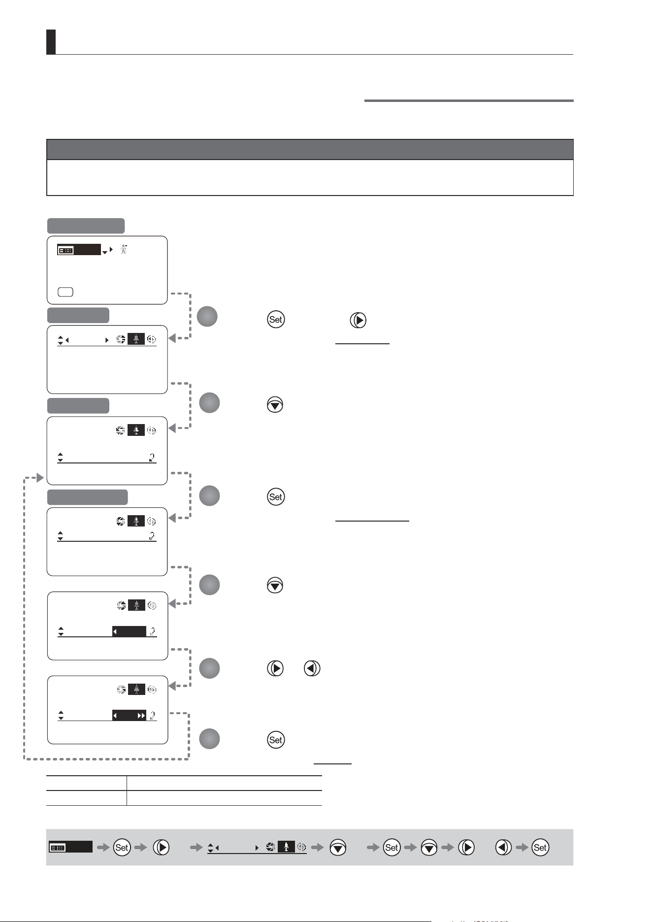
E136
4. Operation in Full Mode
Specifying Zoom Servo Start Responsiveness
Specify initial responsiveness in zooming (using seesaw switch, for example) as needed.
Important
First, switch to the user for whom the settings apply.
(For instructions, see “4.1.3 Switching Users” or “4.2.1 User Screen Settings: Switching Users.”)
Tracking: OFF
Movement
Zoom
[]
CurveMode
Tracking:
Movement
Zoom
Stop:
Start:
[]
99
91
Movement
Zoom
Stop:
Start:
[]
D99
91
Movement
Zoom
Stop:
Start:
[]
97
91
OFF
Movement
CurveMode
Zoom
[]
[ I-Gain ]
[Adj]
[]
MENU
1
A
Fr1P
[ Basic ]
[Trk]
OFF
[I-Tq]H
Press once and four times.
The display switches to the Zoom screen.
Press twice.
[Movement] is underlined.
Press .
The display switches to the Movement screen.
Press .
The display reverts to Screen A.
Press .
[Start] is underlined.
The previous or default value is highlighted.
Press or .
Press left or right until you reach the desired function.
Initial Top Screen
Zoom Screen
Screen A
Movement Screen
Options 00 to
(D)
99
Description Start gradually Start quickly
(D): Default value
MENU
× 4
Zoom
[ ]
× 2 or
1
2
3
4
5
6
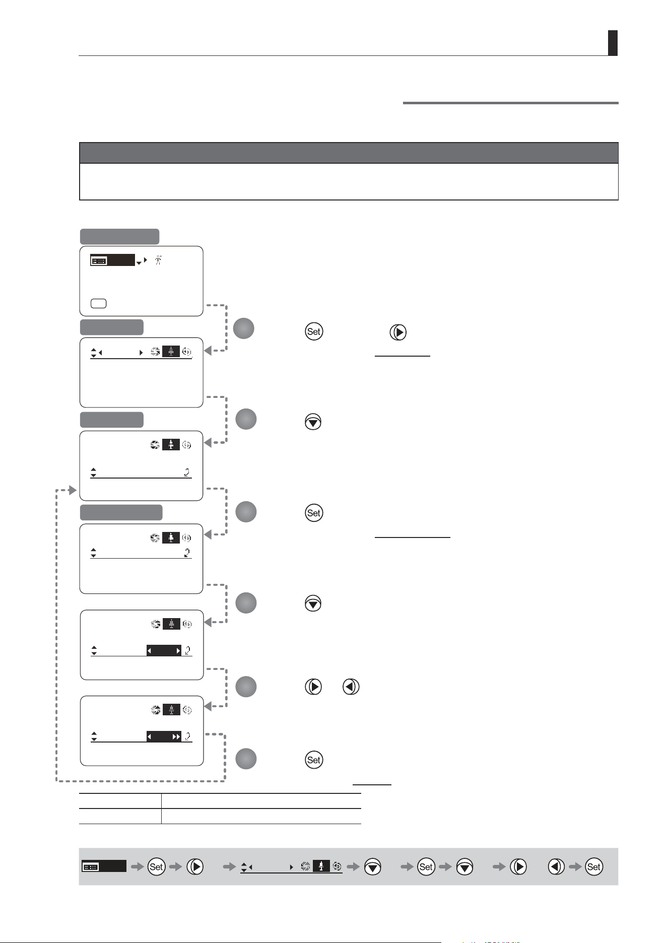
E137
4. Operation in Full Mode
Specifying Zoom Servo Stop Responsiveness
Specify nal responsiveness in zooming (using seesaw switch, for example) as needed.
Important
First, switch to the user for whom the settings apply.
(For instructions, see “4.1.3 Switching Users” or “4.2.1 User Screen Settings: Switching Users.”)
Movement
Zoom
Stop:
Start:
[]
99
91
Movement
Zoom
End:
Stop:
[]
D91
99
Movement
Zoom
End:
Stop:
[]
89
99
Tracking: OFF
Movement
Zoom
[]
CurveMode
Tracking:
OFF
Movement
CurveMode
Zoom
[]
[ I-Gain ]
[Adj]
[]
MENU
1
A
Fr1P
[ Basic ]
[Trk]
OFF
[I-Tq]H
Press once and four times.
The display switches to the Zoom screen.
Press twice.
[Movement] is underlined.
Press .
The display switches to the Movement screen.
Press .
The display reverts to Screen A.
Press twice.
[Start] is underlined.
The previous or default value is highlighted.
Press or .
Press left or right until you reach the desired function.
Initial Top Screen
Zoom Screen
Screen A
Movement Screen
Options 00 to 99
Description Stop gradually Stop quickly
Default value: 91
MENU
× 4
Zoom
[ ]
× 2 × 2 or
1
2
3
4
5
6
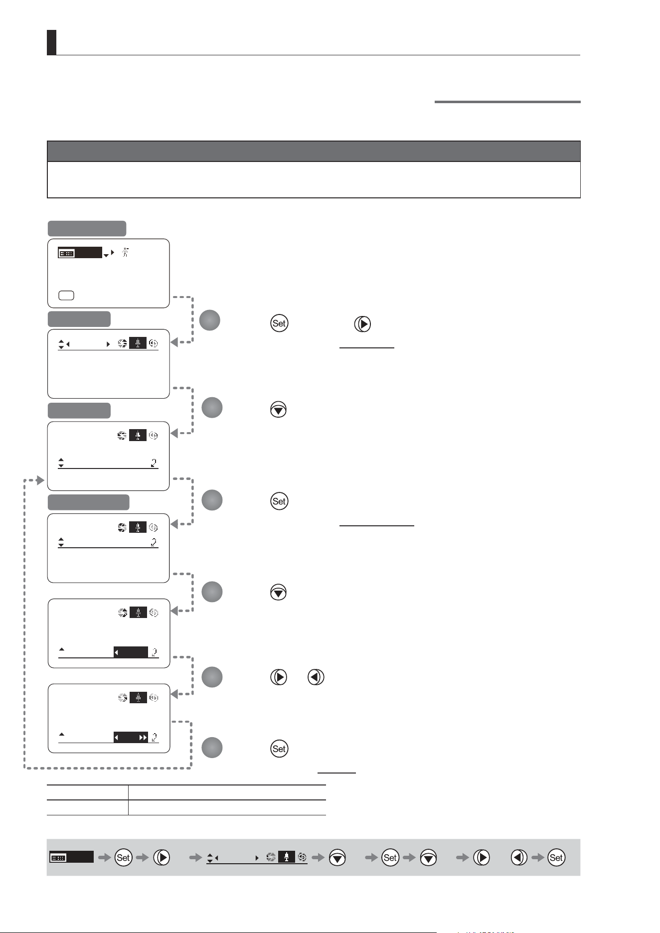
E138
4. Operation in Full Mode
Specifying Zoom Mechanical End Stop Responsiveness
Specify nal responsiveness at the mechanical end in zooming (using the seesaw switch, for example) as needed.
Important
First, switch to the user for whom the settings apply.
(For instructions, see “4.1.3 Switching Users” or “4.2.1 User Screen Settings: Switching Users.”)
Tracking: OFF
Movement
Zoom
[]
CurveMode
Tracking:
OFF
Movement
CurveMode
Zoom
[]
Movement
Zoom
Stop:
Start:
[]
99
91
Movement
Zoom
End:
Stop:
[]
D99
91
Movement
Zoom
End:
Stop:
[]
97
91
[ I-Gain ]
[Adj]
[]
MENU
1
A
Fr1P
[ Basic ]
[Trk]
OFF
[I-Tq]H
Press once and four times.
The display switches to the Zoom screen.
Press twice.
[Movement] is underlined.
Press .
The display switches to the Movement screen.
Press .
The display reverts to Screen A.
Press three times.
[End] is underlined.
The previous or default value is highlighted.
Press or .
Press left or right until you reach the desired function.
Initial Top Screen
Zoom Screen
Screen A
Movement Screen
Options 00 to
(D)
99
Description Stop gradually Stop quickly
(D): Default value
MENU
× 4
Zoom
[ ]
× 2 × 3 or
1
2
3
4
5
6
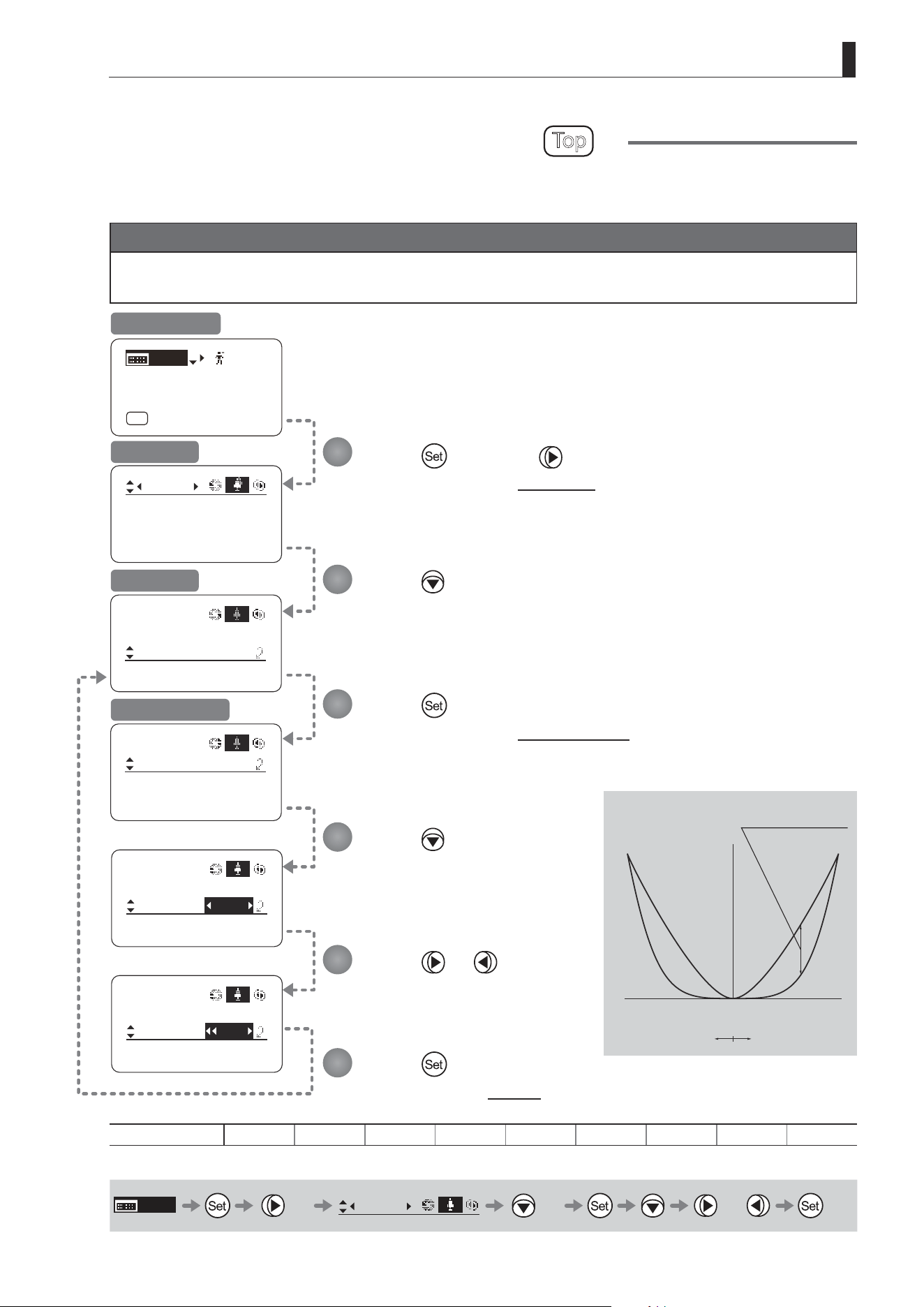
E139
4. Operation in Full Mode
Tracking: OFF
Movement
Zoom
[]
CurveMode
CurveMode
Zoom
Demand:
Seesaw:
[]
5
5
CurveMode
Zoom
[]
OFF
CurveMode
Zoom
Demand:
Seesaw:
[]
5
D5
CurveMode
Zoom
Demand:
Seesaw:
[]
5
7
SpeedAdj
Movement
[ I-Gain ]
[Adj]
[]
MENU
1
A
Fr1P
[ Basic ]
[Trk]
OFF
[I-Tq]H
Specifying Seesaw Switch Responsiveness
Top
Congure the responsiveness of zoom speed adjustment in response to pressing the zoom seesaw switch.
(Note: Another screen is displayed when this setting is congured.)
Important
First, switch to the user for whom the settings apply.
(For instructions, see “4.1.3 Switching Users” or “4.2.1 User Screen Settings: Switching Users.”)
Press once and four times.
The display switches to the Zoom screen.
Press or .
Press left or right until you reach
the desired function.
Press three times.
[CurveMode] is underlined.
Press .
[Seesaw] is underlined.
The previous or default value is
highlighted.
Press .
The display switches to the CurveMode screen.
Press .
The display reverts to Screen A.
Initial Top Screen
Zoom Screen
Screen A
CurveMode Screen
Options 1 2 3 4
(D)
5 6 7 8 9
(D): Default value
MENU
× 4
Zoom
[ ]
× 3 or
1
2
3
4
5
6
(1)
(9)
Responsiveness to
zoom mode adjustment
Maximum
Zoom Speed
Wide Angle Telephoto
Extent of pressing the zoom seesaw switch
Zoom Direction
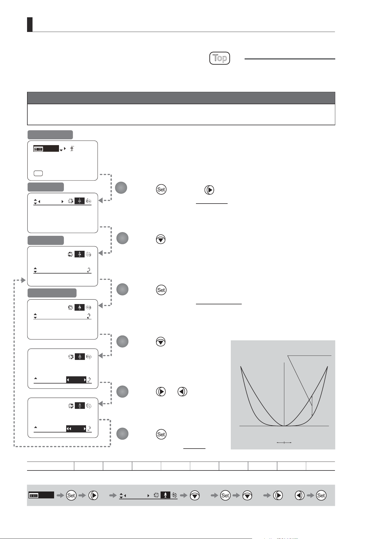
E140
4. Operation in Full Mode
Specifying Analog Demand Responsiveness
Top
Congure the responsiveness of zoom speed adjustment in response to pressing the analog demand thumb ring.
(Note: Another screen is displayed when this setting is congured.)
Important
First, switch to the user for whom the settings apply.
(For instructions, see “4.1.3 Switching Users” or “4.2.1 User Screen Settings: Switching Users.”)
CurveMode
Zoom
Demand:
Seesaw:
[]
5
5
CurveMode
Zoom
[]
OFF
SpeedAdj
Movement
CurveMode
Zoom
Demand:
Seesaw:
[]
5
D5
CurveMode
Zoom
Demand:
Seesaw:
[]
5
7
Tracking: OFF
Movement
Zoom
[]
CurveMode
[ I-Gain ]
[Adj]
[]
MENU
1
A
Fr1P
[ Basic ]
[Trk]
OFF
[I-Tq]H
Press once and four times.
The display switches to the Zoom screen.
Press three times.
[CurveMode] is underlined.
Press .
The display switches to the CurveMode screen.
Press .
The display reverts to Screen A.
Press twice.
[Demand] is underlined.
The previous or default value is
highlighted.
Press or .
Press left or right until you reach
the desired function.
Initial Top Screen
Zoom Screen
Screen A
CurveMode Screen
Options 1 2 3 4
(D)
5 6 7 8 9
(D): Default value
MENU
× 4
Zoom
[ ]
× 3 × 2 or
1
2
3
4
5
6
(1)
(9)
Responsiveness to
zoom mode adjustment
Maximum
Zoom Speed
Wide Angle Telephoto
Extent of tilting the analog demand
Zoom Direction
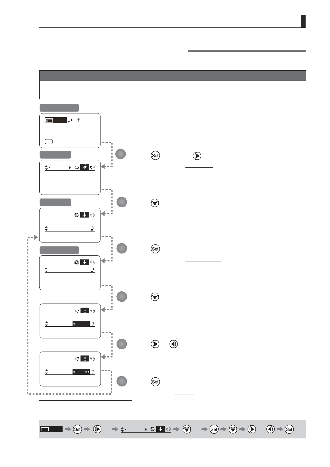
E141
4. Operation in Full Mode
Specifying Maximum Zoom Speed Control
Specify the maximum speed to which the zoom speed can be adjusted using the drive unit knob.
Important
First, switch to the user for whom the settings apply.
(For instructions, see “4.1.3 Switching Users” or “4.2.1 User Screen Settings: Switching Users.”)
SpeedAdj
Zoom
Min:
Max:
[]
99
01
CurveMode
SpeedAdj
Control: Sped
Zoom
[]
SpeedAdj
Zoom
Min:
Max:
[]
D99
01
SpeedAdj
Zoom
Min:
Max:
[]
97
01
Tracking: OFF
Movement
Zoom
[]
CurveMode
[ I-Gain ]
[Adj]
[]
MENU
1
A
Fr1P
[ Basic ]
[Trk]
OFF
[I-Tq]H
Press once and four times.
The display switches to the Zoom screen.
Press four times.
[SpeedAdj] is underlined.
Press .
The display switches to the SpeedAdj screen.
Press .
The display reverts to Screen A.
Press .
[Max] is underlined.
The previous or default value is highlighted.
Press or .
Press left or right until you reach the desired function.
Initial Top Screen
Zoom Screen
Screen A
SpeedAdj Screen
Options Min. value–
(D)
99
(D): Default value
MENU
× 4
Zoom
[ ]
× 4 or
1
2
3
4
5
6
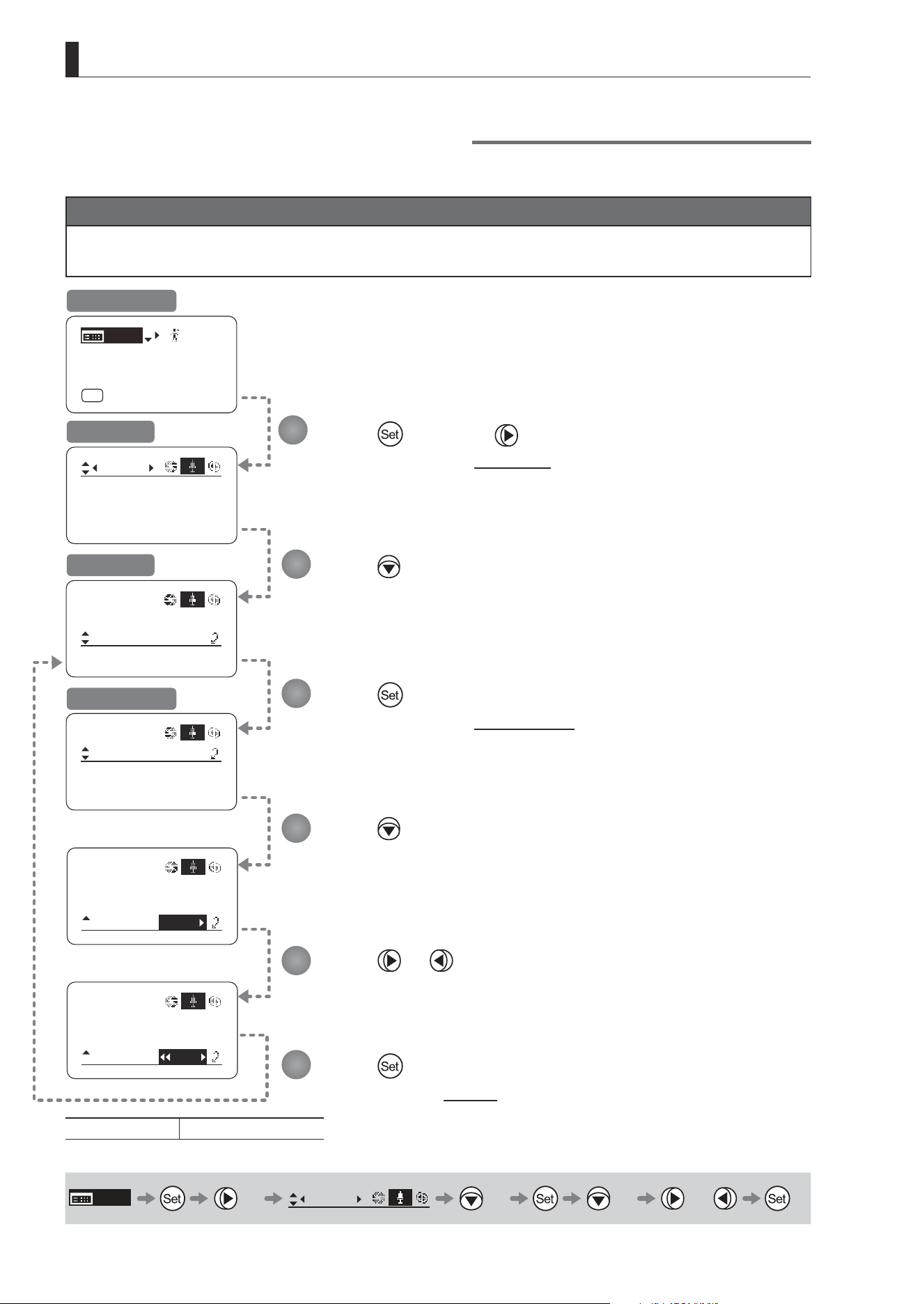
E142
4. Operation in Full Mode
Specifying Minimum Zoom Speed Control
Specify the minimum speed to which the zoom speed can be adjusted using the drive unit knob.
Important
First, switch to the user for whom the settings apply.
(For instructions, see “4.1.3 Switching Users” or “4.2.1 User Screen Settings: Switching Users.”)
Tracking: OFF
Movement
Zoom
[]
CurveMode
SpeedAdj
Zoom
Min:
Max:
[]
99
01
CurveMode
SpeedAdj
Control: Sped
Zoom
[]
SpeedAdj
Zoom
Min:
Max:
[]
99
D01
SpeedAdj
Zoom
Min:
Max:
[]
03
99
[ I-Gain ]
[Adj]
[]
MENU
1
A
Fr1P
[ Basic ]
[Trk]
OFF
[I-Tq]H
Press once and four times.
The display switches to the Zoom screen.
Press four times.
[SpeedAdj] is underlined.
Press .
The display switches to the SpeedAdj screen.
Press .
The display reverts to Screen A.
Press twice.
[Min] is underlined.
The previous or default value is highlighted.
Press or .
Press left or right until you reach the desired function.
Initial Top Screen
Zoom Screen
Screen A
SpeedAdj Screen
Options
(D)
01–Max. value
(D): Default value
MENU
× 4
Zoom
[ ]
× 4 × 2 or
1
2
3
4
5
6
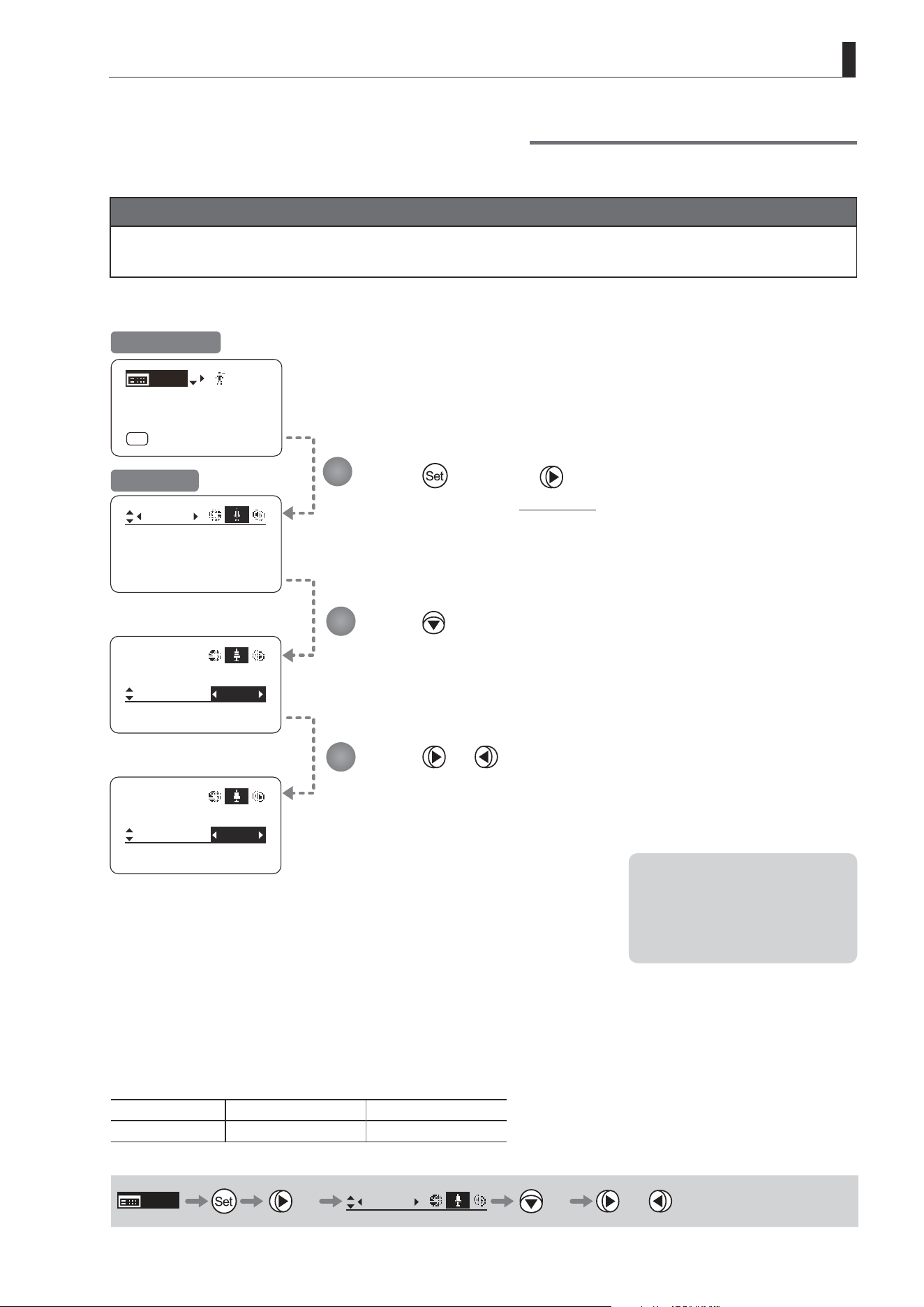
E143
4. Operation in Full Mode
Specifying Servo Type from Zoom Demand
Specify either the speed or position servo as the type of servo to use from the zoom demand.
Important
First, switch to the user for whom the settings apply.
(For instructions, see “4.1.3 Switching Users” or “4.2.1 User Screen Settings: Switching Users.”)
Tracking: OFF
Movement
Zoom
[]
CurveMode
SpeedAdj
Control:
VR-Dem: ON
Zoom
[]
Sped
SpeedAdj
Control:
VR-Dem: ON
Zoom
[]
Posi
[ I-Gain ]
[Adj]
[]
MENU
1
A
Fr1P
[ Basic ]
[Trk]
OFF
[I-Tq]H
Press once and four times.
The display switches to the Zoom screen.
Press ve times.
[Control] is underlined.
The previous or default function is highlighted.
Press or .
Press left or right to switch the function to {Sped} or {Posi}.
Initial Top Screen
Zoom Screen
Options
(D)
Sped Posi
Description Speed servo Position servo
(D): Default value
MENU
× 4
Zoom
[ ]
× 5 or
1
2
3
Note: Selecting {Posi} will disable
the seesaw switch.
Additionally, only one demand
connector can be connected
when {Posi} is selected.
Normally, select {Sped}.
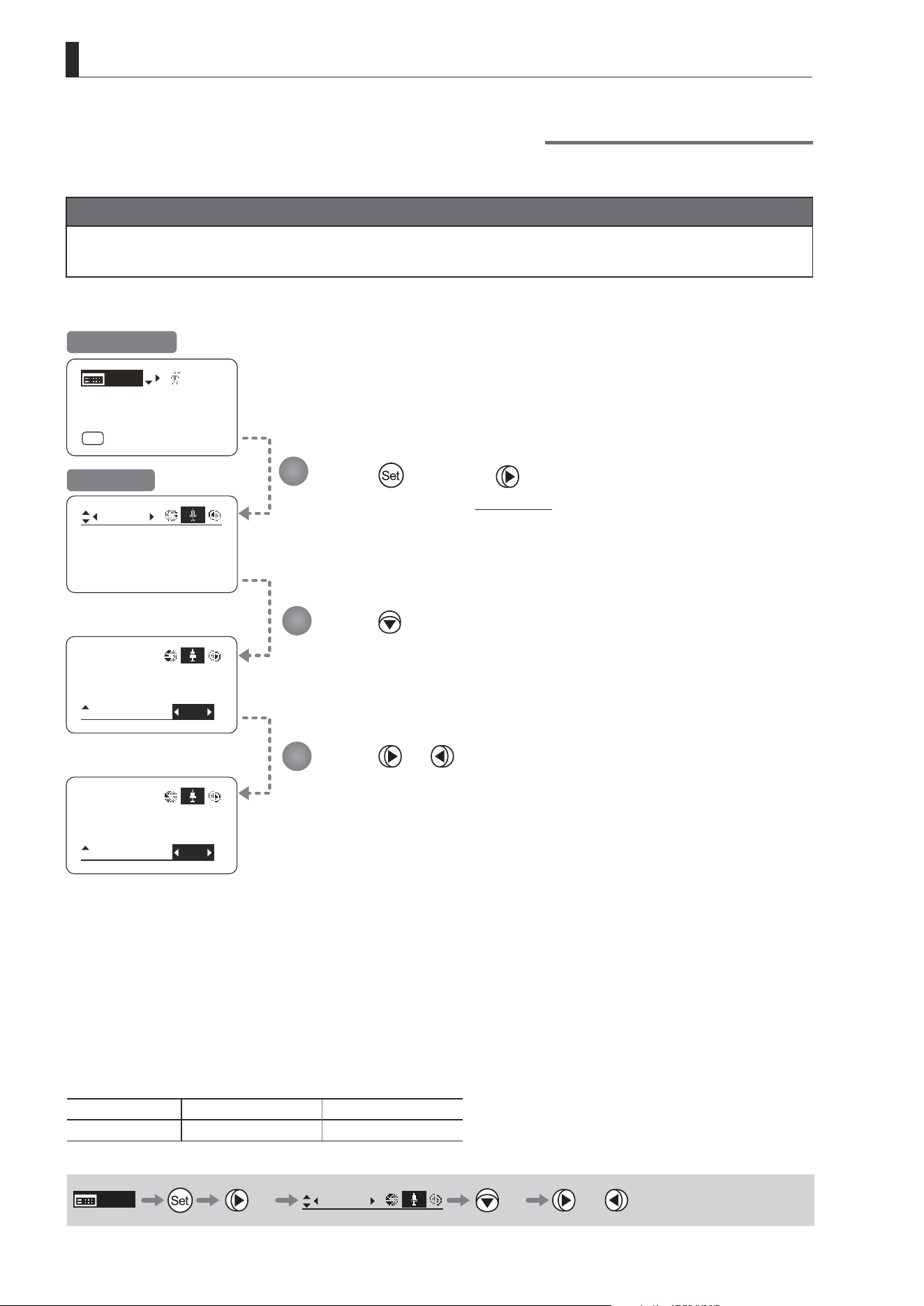
E144
4. Operation in Full Mode
Demand-Based Zoom Speed Adjustment ON/OFF
Enable or disable adjustment of the maximum drive unit zoom speed based on the zoom demand.
Important
First, switch to the user for whom the settings apply.
(For instructions, see “4.1.3 Switching Users” or “4.2.1 User Screen Settings: Switching Users.”)
Tracking: OFF
Movement
Zoom
[]
CurveMode
Control:
VR-Dem:
Zoom
[]
ON
Sped
Control:
VR-Dem:
Zoom
[]
OFF
Sped
[ I-Gain ]
[Adj]
[]
MENU
1
A
Fr1P
[ Basic ]
[Trk]
OFF
[I-Tq]H
SpeedAdj
SpeedAdj
Press once and four times.
The display switches to the Zoom screen.
Press six times.
[VR-Dem] is underlined.
The previous or default function is highlighted.
Press or .
Press left or right to switch the function {ON} or {OFF}.
Initial Top Screen
Zoom Screen
Options
(D)
ON OFF
Description Enabled Disabled
(D): Default value
MENU
× 4
Zoom
[ ]
× 6 or
1
2
3

E145
4. Operation in Full Mode
4.2.6 Focus Screen Settings
The following setting items can be congured on the Focus screen.
Specifying Focus Demand Responsiveness
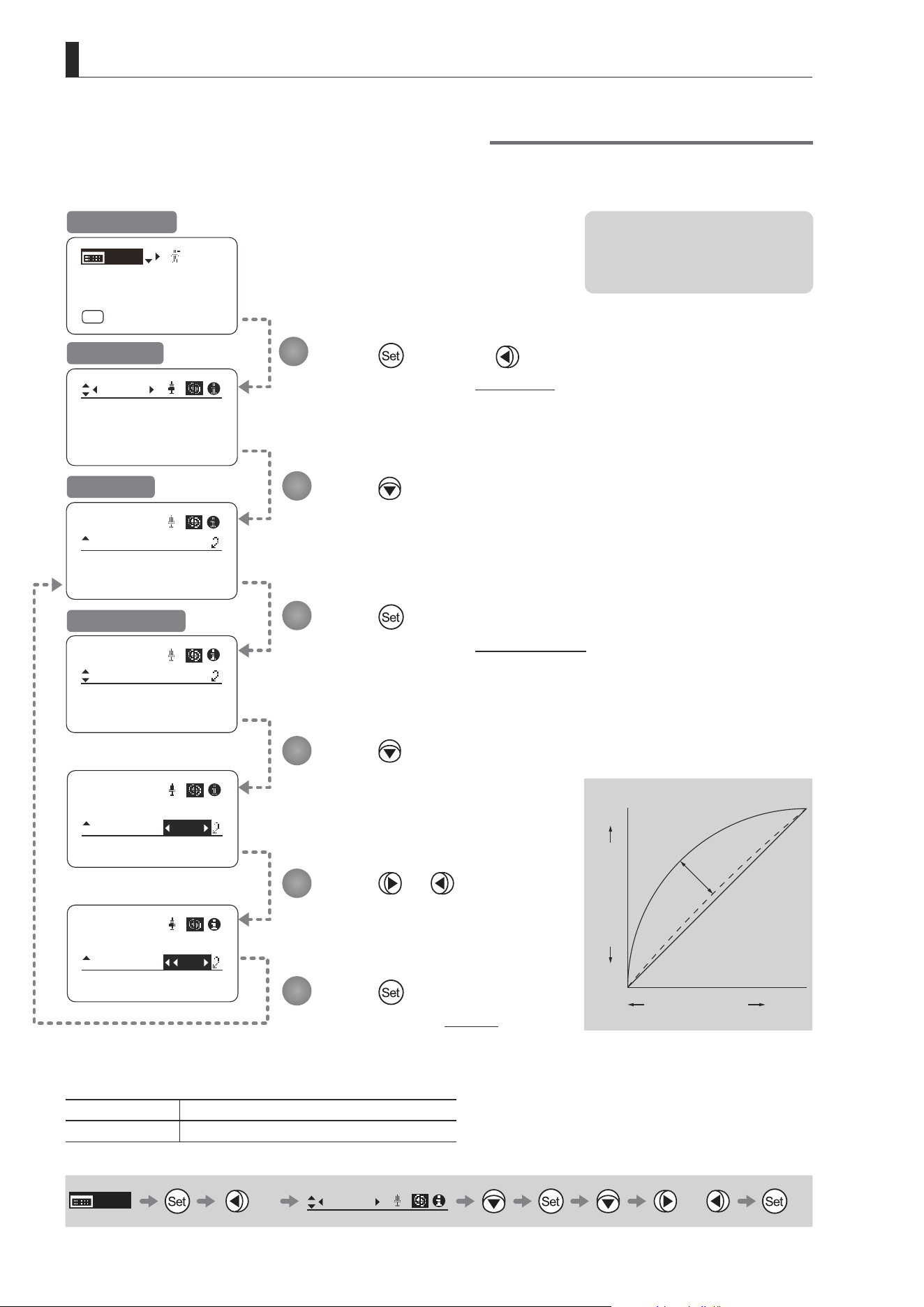
E146
4. Operation in Full Mode
Specifying Focus Demand Responsiveness
Specify responsiveness in analog focus demand operations as needed.
Focus
[]
CurveMode
ADemand: 5
Focus
[]
CurveMode
CurveMode
ADemand: D5
Focus
[]
CurveMode
ADemand: 7
Focus
[]
CurveMode
Focus
[]
[ I-Gain ]
[Adj]
[]
MENU
1
A
Fr1P
[ Basic ]
[Trk]
OFF
[I-Tq]H
Press once and three times.
The display switches to the Focus screen.
Press .
[CurveMode] is underlined.
Press .
The display switches to the CurveMode screen.
Press .
The display reverts to Screen A.
Press .
[ADemand] is underlined.
The previous or default value is
highlighted.
Press or .
Press left or right until you reach
the desired function.
Initial Top Screen
Focus Screen
Screen A
CurveMode Screen
Options 1 to 9
Description Large curve Small curve
Default value: 5
MENU
× 3
Focus
[ ]
or
1
2
3
4
5
6
Note: These settings take eect
when the curve selection
switch on the focus demand is
set toward FAR.
Standard
1
9
Innity
Close
Range
Focus Position
Knob Position

E147
4. Operation in Full Mode
4.2.7 Info Screen Settings
The following setting items can be congured on the Info screen.
Checking Serial Numbers
Specifying the 3D Function (For information on specifying the 3D function, see the instruction manual of the BC-100 3D
cable.)
Specifying Encoder Output
Serial Communication with Camera ON/OFF
Specifying the Input Route for Command Signals from the Camera
Specifying the
Technology Distance Unit
Checking Lens–Drive Unit Communication
Conguring Settings in System Mode (Used by Canon Service Technicians Only)
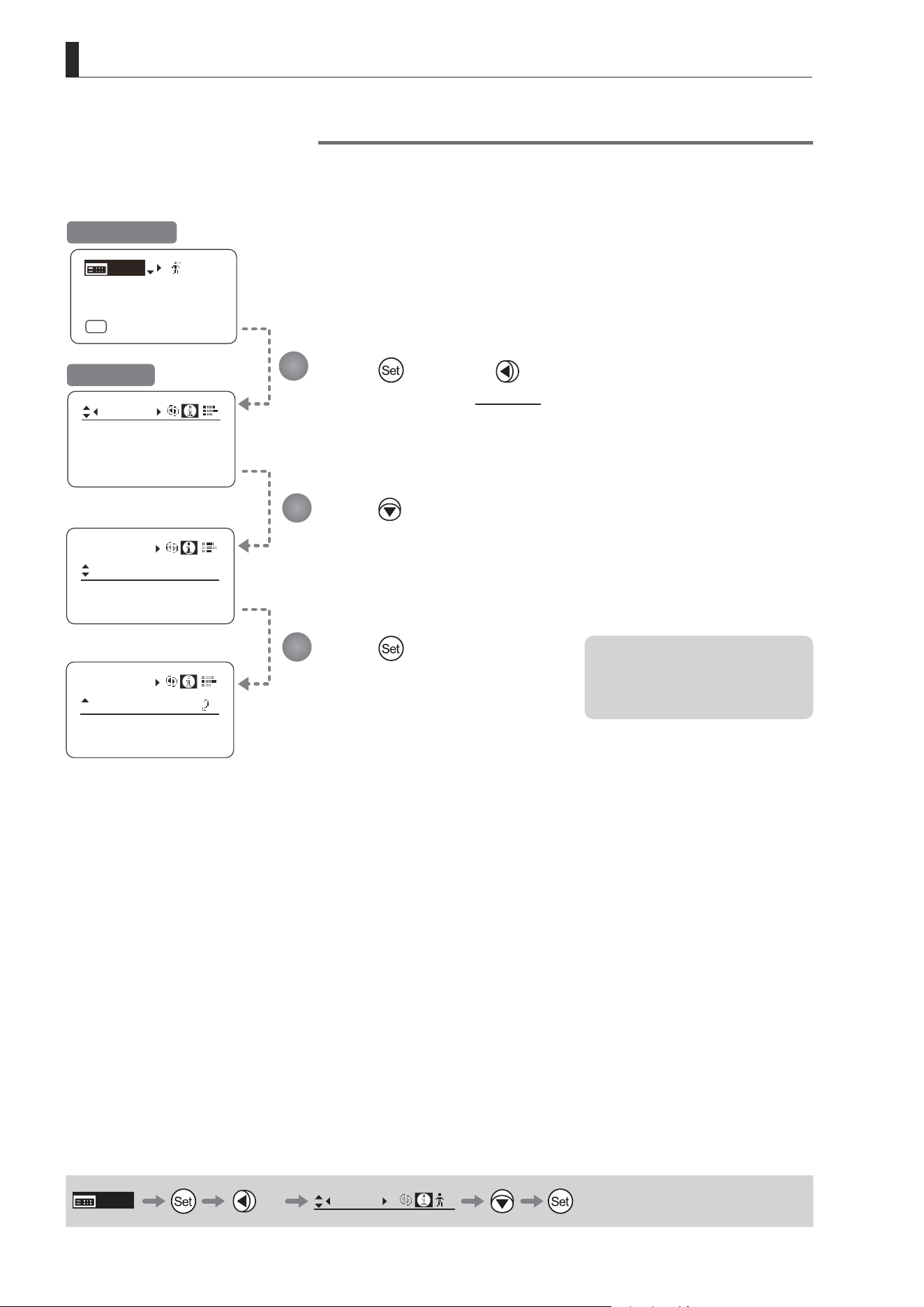
E148
4. Operation in Full Mode
Info
D.U.:
00000000
Lens:
00000000
S/N
[ I-Gain ]
[Adj]
[]
MENU
1
A
Fr1P
[ Basic ]
[Trk]
OFF
[I-Tq]H
Info
S/N
Info
S/N
Encoder: OFF
3D:
OFF
Encoder: OFF
3D:
OFF
Checking Serial Numbers
Check lens and drive unit serial numbers as needed.
Press once and twice.
The display switches to the Info screen.
Press .
[S/N] is underlined.
Press .
The lens and drive unit serial numbers are
displayed.
Initial Top Screen
Info Screen
MENU
× 2
Info
1
1
2
3
Note: The serial number of the lens
is not displayed when no
power is being supplied to the
lens from the camera mount.
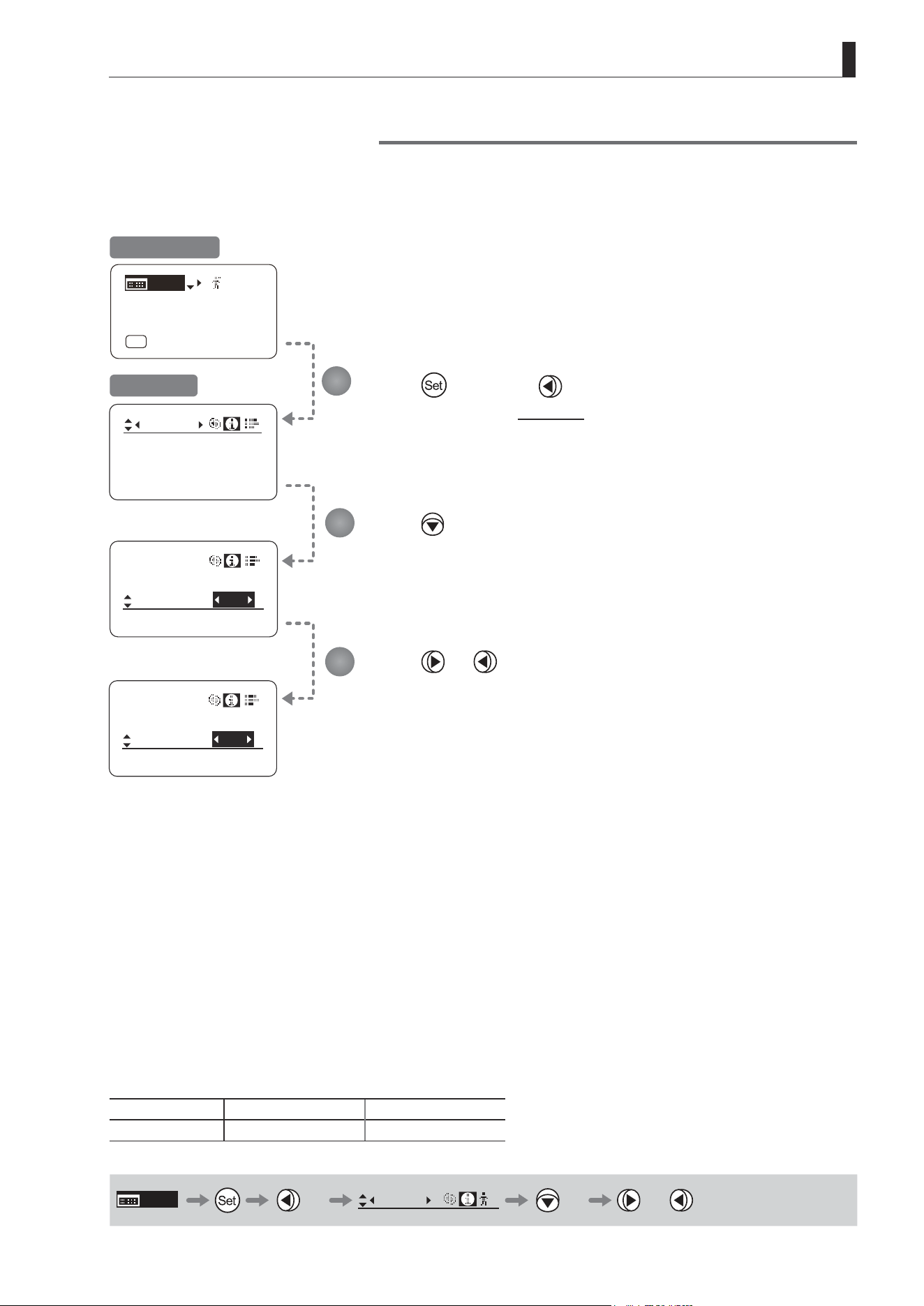
E149
4. Operation in Full Mode
Specifying Encoder Output
Enable or disable encoder output as needed. Enabling output enables virtual connector output. For details, contact
Canon or your dealer.
INDOFF
[ I-Gain ]
[Adj]
[ ]
MENU
1
A
Fr1P
[ Basic ]
[Trk]
OFF
[I-Tq]H
Info
Info
CamSeri:
ON
Encoder:
IND
ON
Info
CamSeri:
ON
Encoder:
Encoder: OFF
S/N
3D:
OFF
3D:
OFF
3D:
OFF
Press once and twice.
The display switches to the Info screen.
Press three times.
[Encoder] is underlined.
Press or .
Press left or right to switch the function {ON} or {OFF}.
Initial Top Screen
Info Screen
Options
(D)
OFF ON
Description Output disabled Output enabled
(D): Default value
MENU
× 2
Info
1
× 3 or
1
2
3
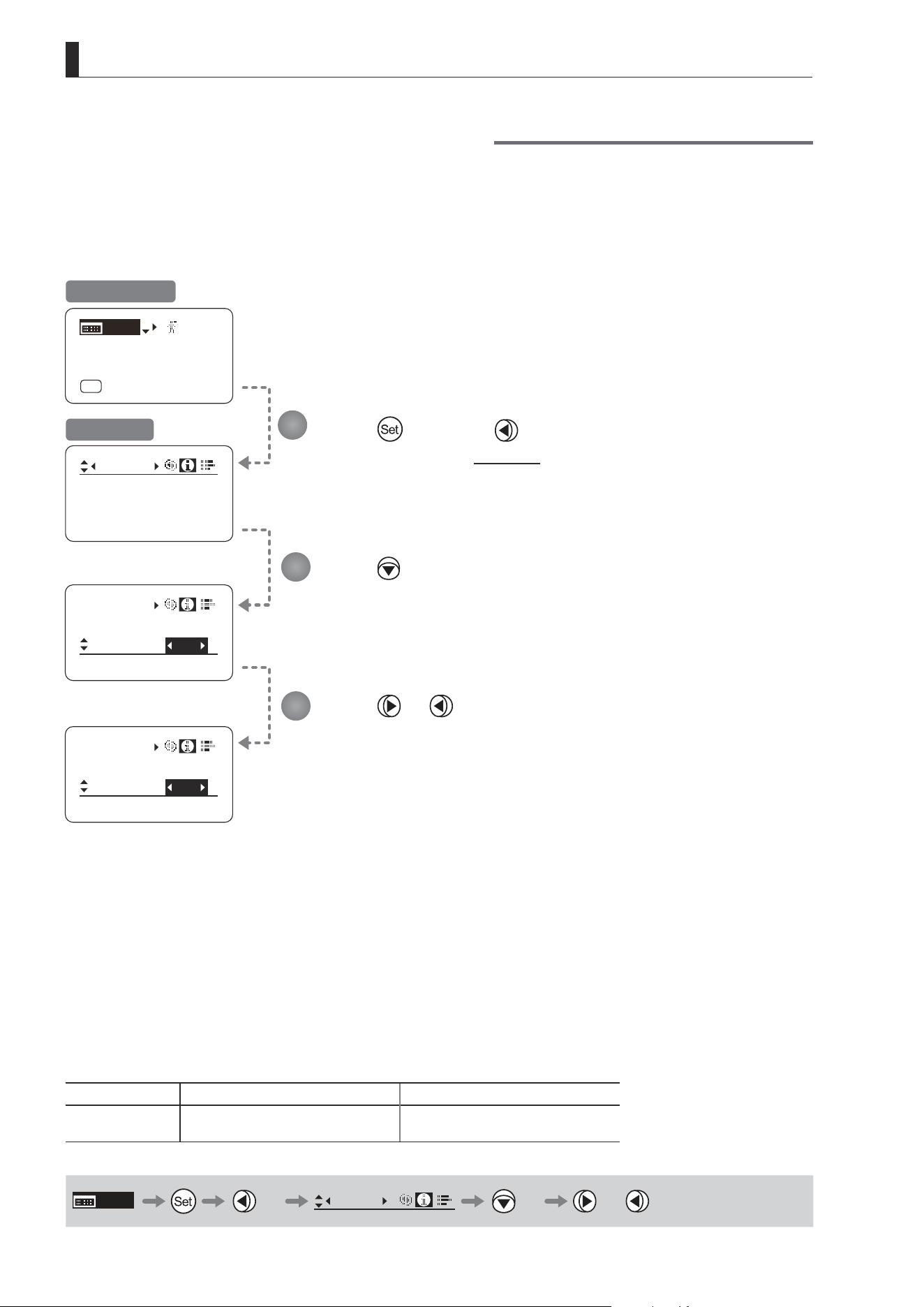
E150
4. Operation in Full Mode
Serial Communication with Camera ON/OFF
Two types of camera–lens interfaces are available: analog control or control via serial communication. This setting
enables you to switch between auto control detection and analog control.
By default, this setting is ON, enabling auto detection of whether serial or analog control is used.
To restrict the interface to analog control, set it to OFF.
Info
CamSeri:
Encoder:
OFF
I/Fprior
I/Fprior
Mount
Mount
ON
[ I-Gain ]
[Adj]
[]
MENU
1
A
Fr1P
[ Basic ]
[Trk]
OFF
[I-Tq]H
Info
Encoder:
OFF
S/N
Info
CamSeri:
Encoder:
OFF
OFF
OFF
3D:
Press once and twice.
The display switches to the Info screen.
Press four times.
[CamSeri] is underlined.
Press or .
Press left or right to switch the function {ON} or {OFF}.
Initial Top Screen
Info Screen
Options
(D)
ON OFF
Description
Serial communication with the camera
Enabled
Serial communication with the camera
Disabled
(D): Default value
MENU
× 2
Info
× 4 or
1
2
3

E151
4. Operation in Full Mode
Info
Encoder:
OFF
S/N
IND
ON
Info
CamSeri:
I/Fprior
Cable
/ i
IND
ON
Info
CamSeri:
Mount
/ i
I/Fprior
OFF
3D
[ I-Gain ]
[Adj]
[]
MENU
1
A
Fr1P
[ Basic ]
[Trk]
OFF
[I-Tq]H
Specifying the Input Route for Command Signals from the Camera
There are two input routes for command signals from the camera: via the mount and via the 12-pin cable. This setting
species the input route for command signals from the camera. The default setting is “Mount,” and in this case command
signals received via the mount are given priority.
However, the command signals via the 12-pin cable are received automatically if no command signals are input via the
mount. When the “Cable” setting is selected, only command signals received via the 12-pin cable are used.
Press once and twice.
The display switches to the Info screen.
Press ve times.
[I/Fprior] is underlined.
Press or .
Press left or right to switch the function {Cable} or {Mount}.
Initial Top Screen
Info Screen
Options
(D)
Mount Cable
Description Via mount Via 12-pin cable
(D): Default value
MENU
× 2
Info
× 5 or
1
2
3
Note: Set {Mount} when using the
auto focus function of the
camera. (For the camera models
that support the auto focus
function, contact your Canon
dealer.)

E152
4. Operation in Full Mode
State:
Info
I/Fprior
Mount
/ i
Info
3D:
OFF
S/N
/ i
Units:
Meters
Info
[ I-Gain ]
[Adj]
[]
MENU
1
A
Fr1P
[ Basic ]
[Trk]
OFF
[I-Tq]H
/ i
Units: Feet
Info
/ i
Units:
Feet
Info
Encoder:
OFF
Specifying the Technology Distance Unit
When
Technology is used (only when a PL mount camera is attached), it is possible to specify the initial setting for the unit (feet
or meters) used to express distances in information sent to the camera. Accordingly, information sent for the actual subject distance,
hyperfocal distance, subject distance at close range and innity, and entrance pupil position is expressed in the specied unit.
Note
Any distance unit set on the camera takes precedence.
Press once and twice.
The display switches to the Info screen.
Press six times.
[/ i] is underlined.
Press .
Press
.
[Units] is underlined.
The previous or default value is highlighted.
Press or .
Press left or right to switch the function {Feet} or {Meters}.
Options
(D)
Feet Meters
Description Expressed in feet Expressed in meters
(D): Default value
MENU
× 2
Info
× 6 or
1
2
3
4
5
Initial Top Screen
Info Screen
is trademark of Cooke Optics Limited.

E153
4. Operation in Full Mode
State
Info
/ i
Lens
State
Info
Info
Encoder:
OFF
S/N
Lens
State
Info
Lens Interface:
Connected
[ I-Gain ]
[Adj]
[]
MENU
1
A
Fr1P
[ Basic ]
[Trk]
OFF
[I-Tq]H
Adjust
3D:
OFF
Checking Lens–Drive Unit Communication
View the status of communication between the lens and drive unit as follows.
Press once and twice.
The display switches to the Info screen.
Press seven times.
[State] is underlined.
Press .
Press
.
[Lens] is underlined.
Press .
This screen indicates normal
communication.
If “Non-connected” is displayed, contact
Canon or your dealer.
MENU
× 2
Info
× 7
1
2
3
4
5
Initial Top Screen
Info Screen
Note: “Non-connected” is displayed
when no power is being
supplied to the lens from the
camera mount.

E154
4. Operation in Full Mode
4.2.8 Fol. Screen Settings
The following setting items can be congured on the Fol. screen.
Viewing Lens Follow Settings (Iris, Zoom, Focus)
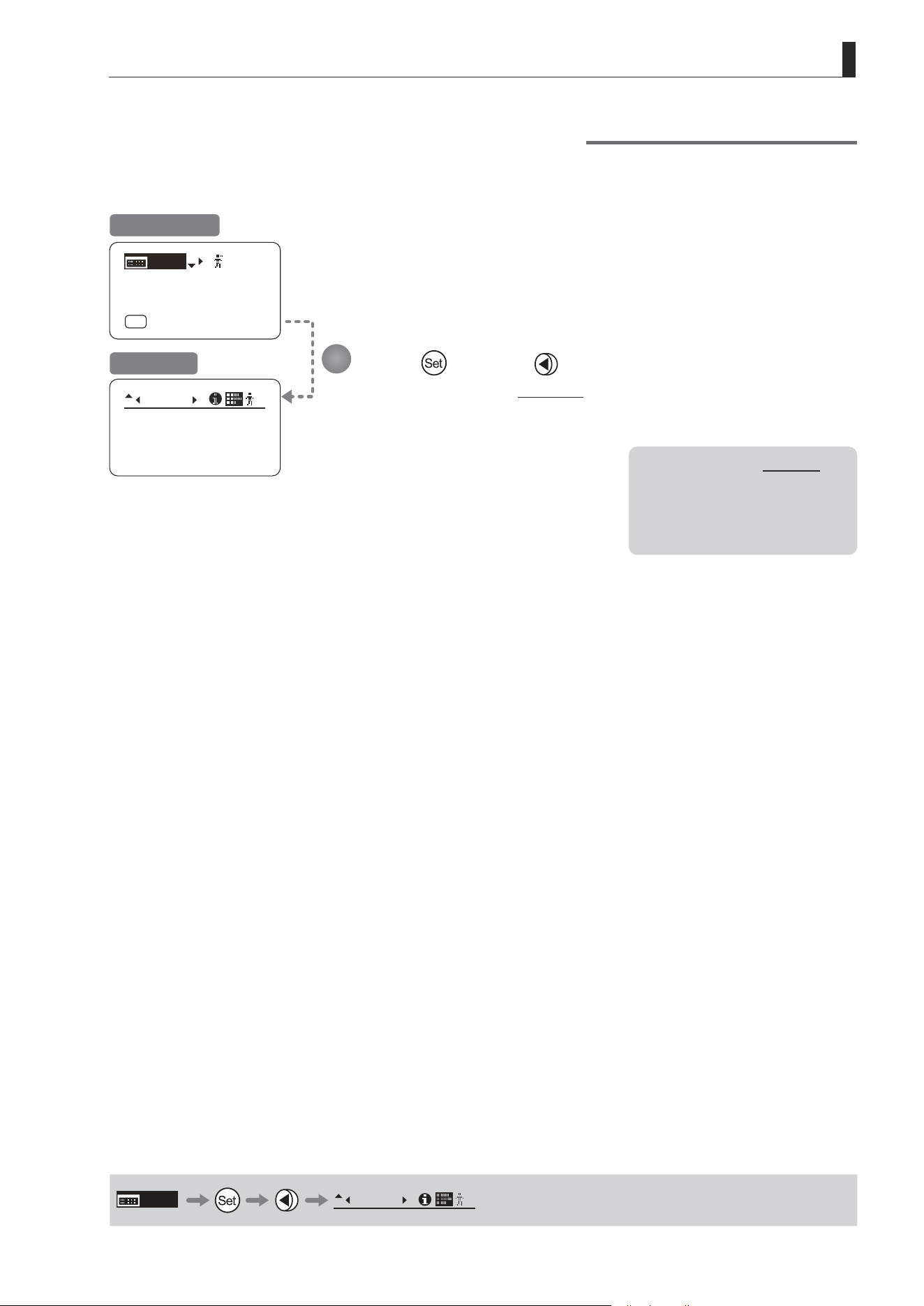
E155
4. Operation in Full Mode
Viewing Lens Follow Settings (Iris, Zoom, Focus)
Indicates values in the full range of mechanical iris, zoom, and focus operations, expressed as relative values in the
range of 0–1000.
Fol.
Iris:
Zoom:
Focus:
0000
1000
0000
1
[ I-Gain ]
[Adj]
[]
MENU
1
A
Fr1P
[ Basic ]
[Trk]
OFF
[I-Tq]H
Press and then .
The display switches to the Fol. screen, showing relative follow iris, zoom, and focus
values.
Initial Top Screen
Fol. Screen
MENU
Fol.
1
1
Note: As long as the Fol. screen is
shown, the display will not
turn o automatically after 2
minutes if left idle.
To turn o the display, press
the Display switch.
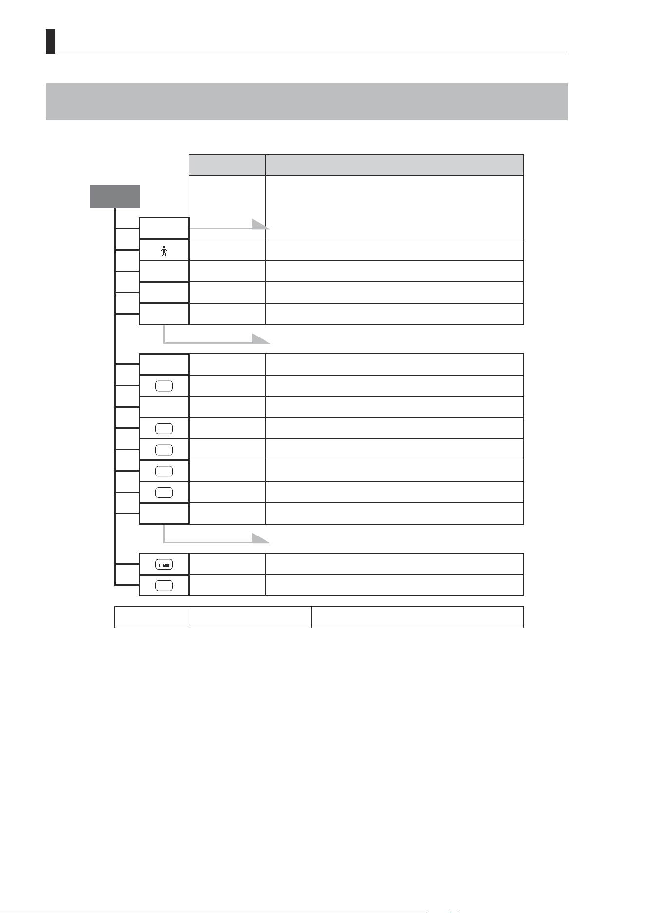
E156
4. Operation in Full Mode
4.3 List of Settings
Default Value Options
Top
MENU To *1 on the next page
[
] 1 1 / 2 / 3 / 4 / 5 / 6 / 7 / 8 / 9 / 0
[Basic] Basic Basic
[Adj] n n / y
[I-Gain]
To *2 on the next page
[Trk] OFF OFF / ON
A
Fr1P VTR / RET / Fr1P / Fr1F / Fr2P / Fr2F / Sped / Shtl / NON
[I-Tq] H H / L
A 1
Shtl VTR / RET / Fr1P / Fr1F / Fr2P / Fr2F / Sped / Shtl / NON
V
VTR VTR / RET / Fr1P / Fr1F / Fr2P / Fr2F / Sped / Shtl
A 2
Fr1P VTR / RET / Fr1P / Fr1F / Fr2P / Fr2F / Sped / Shtl / NON
R
RET VTR / RET / Fr1P / Fr1F / Fr2P / Fr2F / Sped / Shtl
[Z.M.]
To *3 on the next page
Zoom Zoom / Iris
AM
Norm Norm / Reve / Auto / Manu
Escape Operation Jump to user 0 setting status
Hold down both the Display switch and Set key for at least 2
seconds.
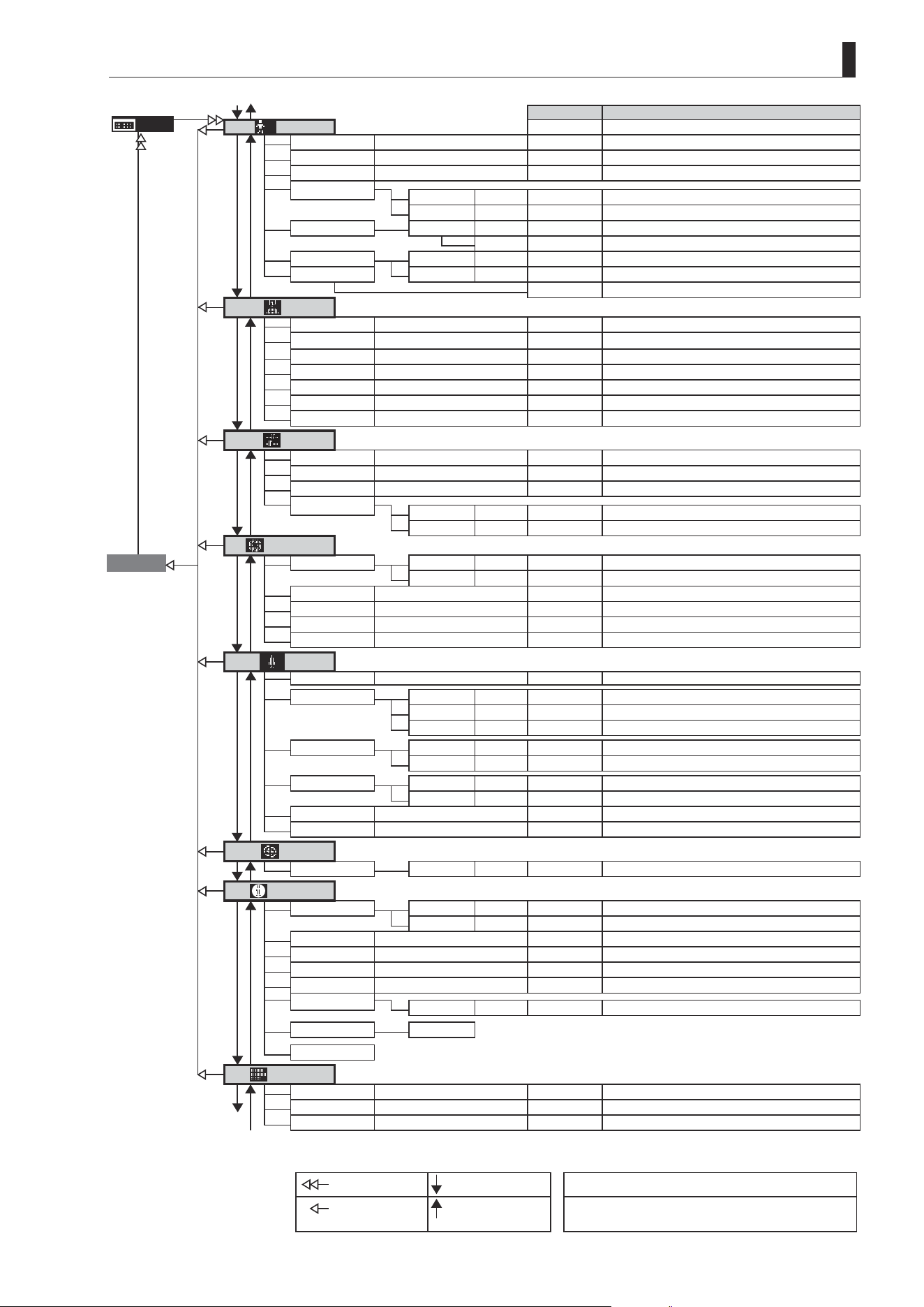
E157
4. Operation in Full Mode
Default Value
Options
MENU
User
*
*1
Mode
Basic Basic / Analog / Full
No. 1 1 / 2 / 3 / 4 / 5 / 6 / 7 / 8 / 9 / 0
Name - - / space / A–Z / a–z / 0–9
ResetAll
User n y / n
AllUser n y / n
Copy To No 1 1 / 2 / 3 / 4 / 5 / 6 / 7 / 8 / 9
Copy n y / n
To Other Lens UserCopy y y / n
Access AllCopy y y / n
Unlock Unlock / Lock
Switch
AUX
Fr1P
VTR / RET / Fr1P / Fr1F / Fr2P / Fr2F / Sped / Shtl / NON
AUX1 Shtl
VTR / RET / Fr1P / Fr1F / Fr2P / Fr2F / Sped / Shtl / NON
AUX2 Fr1P
VTR / RET / Fr1P / Fr1F / Fr2P / Fr2F / Sped / Shtl / NON
VTR VTR
VTR / RET / Fr1P / Fr1F / Fr2P / Fr2F / Sped / Shtl
RET RET
VTR / RET / Fr1P / Fr1F / Fr2P / Fr2F / Sped / Shtl
A/M Norm Norm / Reve / Auto / Manu
SSaw Zoom Zoom / Iris
Preset
Frame1
Zoom Zoom / Focus / Z+F
Frame2 Zoom Zoom / Focus / Z+F
ZSpeed 800 1–800
ZMovement
Start 99 00–99
Stop 91 00–99
Iris
Go Top
[I-Gain]
Auto 50 01–99
*2 Remote 90 01–99
Torque High High / Low
Comp ON ON / OFF
Close OFF OFF / ON
Controller OFF OFF / ON
Zoom
[ ]
Tracking
OFF OFF / ON
Movement Start 99 00–99
Stop 91 00–99
End 99 00–99
CurveMode Seesaw 5 1–9
*3
Demand 5 1–9
SpeedAdj Max 99 Min. value–99
Min 01 01– Max. value
Control Sped Sped / Posi
VR-Dem ON ON / OFF
Focus
CurveMode
ADemand 5 1–9
Info
S/N
Lens 8-digit serial number
D.U. 8-digit serial number
3D
#1
OFF OFF / ON
Encoder OFF OFF / ON
CamSeri ON ON / OFF
I/Fprior Mount Mount / Cable
/i
Unit Feet Feet / Meters
State Lens
Adjust
Fol.
*4
Iris
(**) (0000–1000)
Zoom (**) (0000–1000)
To
*1
Focus (**) (0000–1000)
From
*1
From
*4
To
*4
: Set key operation : Right key operation ( ) : Indicates values that cannot be changed.
: Up key operation : Left key operation #1 : For information on specifying the 3D communication,
see the “3D Cable Instruction Manual.”

Memo

Operation in Analog Mode
5
INFORMATION DISPLAY

E160
5. Operation in Analog Mode
5. Operation in Analog Mode
5.1 Conguration from the Top Screen
To access the Top screen, press the Display switch.
A total of 3 items can be congured on the Top screen in Analog mode. The rst screen displayed is referred to as the
Initial Top screen. Status of some items can be checked simply by accessing this screen.
MENU
IG: 50
[ Basic ]
Initial Top Screen in Analog Mode
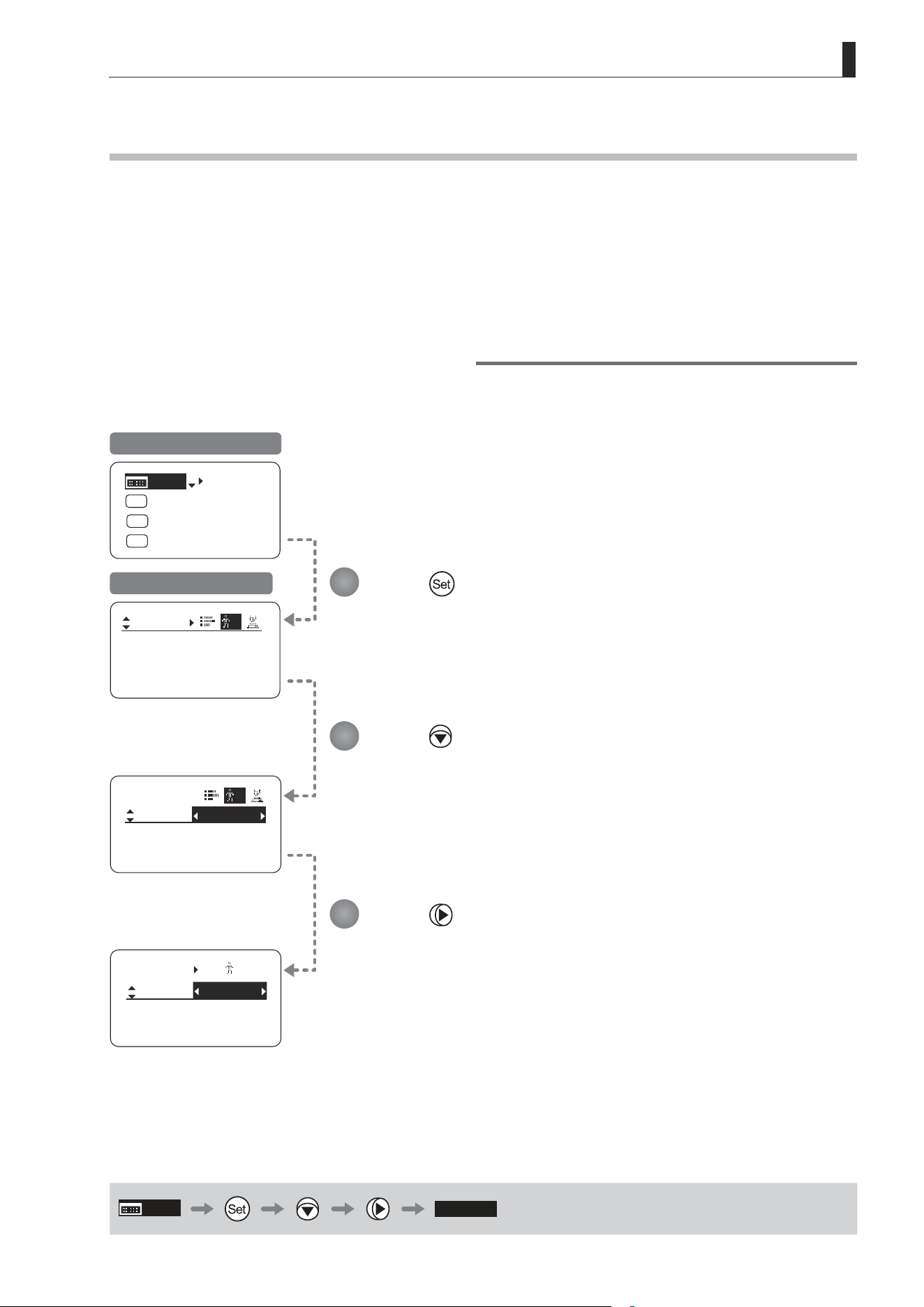
E161
5. Operation in Analog Mode
5.1.1 Selecting Analog Mode
Basic mode is the default mode, but Analog mode can be accessed as follows.
Use this mode for operation of a conventional analog drive unit. Digital functions are not available in this mode.
• Switches labeled VTR, RET, IRIS A/M, and IRIS INST control the respective functions. The rocker switch serves as a
regular zoom switch.
• AUX and MEMO switches are disabled.
• To set auto iris gain adjustment, use either display or trimmer operations.
• Shuttle shot, frame preset, speed preset, and zoom tracking are not available.
Switching from Basic to Analog Mode
Mode:
User
Basic
Access:
ResetAll
B
Unlock
Mode:
User
Basic
Access:
ResetAll
B
Unlock
User
Access:
Mode:
A
Unlock
Analog
[Trk]
OFF
Shtl
A 1
A 2
MENU
IG: 50
A
Fr1P
Fr1P
[I-Tq]H
[Adj]
Initial Top Screen in Basic Mode
User Screen in Basic Mode
MENU
[ Analog ]
Press .
[Basic] is highlighted.
Press .
[Analog] is now highlighted, indicating conrmation.
Press .
1
2
3
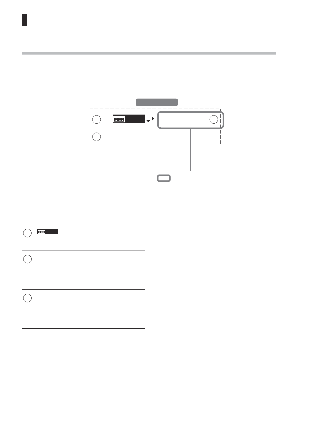
E162
5. Operation in Analog Mode
5.1.2 Top Screen
A total of 3 items can be congured on the Top screen in Analog mode, as shown on the Initial Top screen.
Status of some items can be checked simply by accessing this screen. (Shown in the gure below.
*1
)
MENU
[ Basic ]
IG:50
1
3
2
1
MENU
Menu screen
See “5.2 Conguration from the Menu Screen.”
1 2
IG
Auto iris gain
Adjust the auto iris gain value as needed.
See “5.1.3 Specifying Auto Iris Gain.”
3
[Basic]
Switching to Basic Mode
Switch to Basic mode as needed.
See “5.1.4 Switching to Basic Mode.”
Initial Top Screen
*1
Inside : Items that show the current setting status.
Example: [IG:50] indicates a value of 50 for auto iris gain.
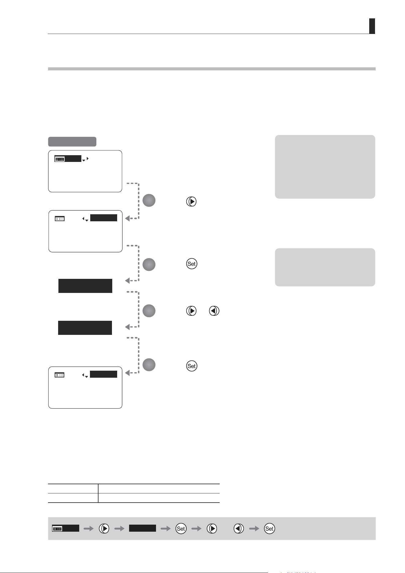
E163
5. Operation in Analog Mode
5.1.3 Specifying Auto Iris Gain [IG]
Although this value is factory-set, it can be adjusted as needed.
To adjust the value, use either the auto iris gain adjustment trimmer (refer to the operation manual "Lens") or display
operations. Regardless of the method of adjustment used, the most recent setting takes precedence.
The same auto iris gain value applies to all users.
Options 01 to 99
Description Minimum gain Maximum gain
Default: Varies depending on the factory-set value, but corresponds to the value determined with the iris gain adjustment trimmer.
MENU
IG: 50
or
IG: 50
IG: 50
IG: 51
IG: 51
MENU
IG: 50
[ Basic ]
IG:50
MENU
MENU
[ Basic ]
IG:51
MENU
MENU
[ Basic ]
Note: Do the following when
adjusting gain while checking
iris operation.
→ Conrm that the drive unit A/M
switch is set to [Auto] mode.
→ Set the camera iris mode to
[Auto].
Note: As you look at the lens iris
ring, set it to the position of
maximum gain at which “focus
hunting” does not occur.
1
2
3
4
Press .
Your selection is now highlighted.
Press .
The display starts blinking.
Press or .
Press left or right until you reach the desired value.
Press .
The display changes from blinking to highlighted, indicating conrmation.
Initial Top Screen
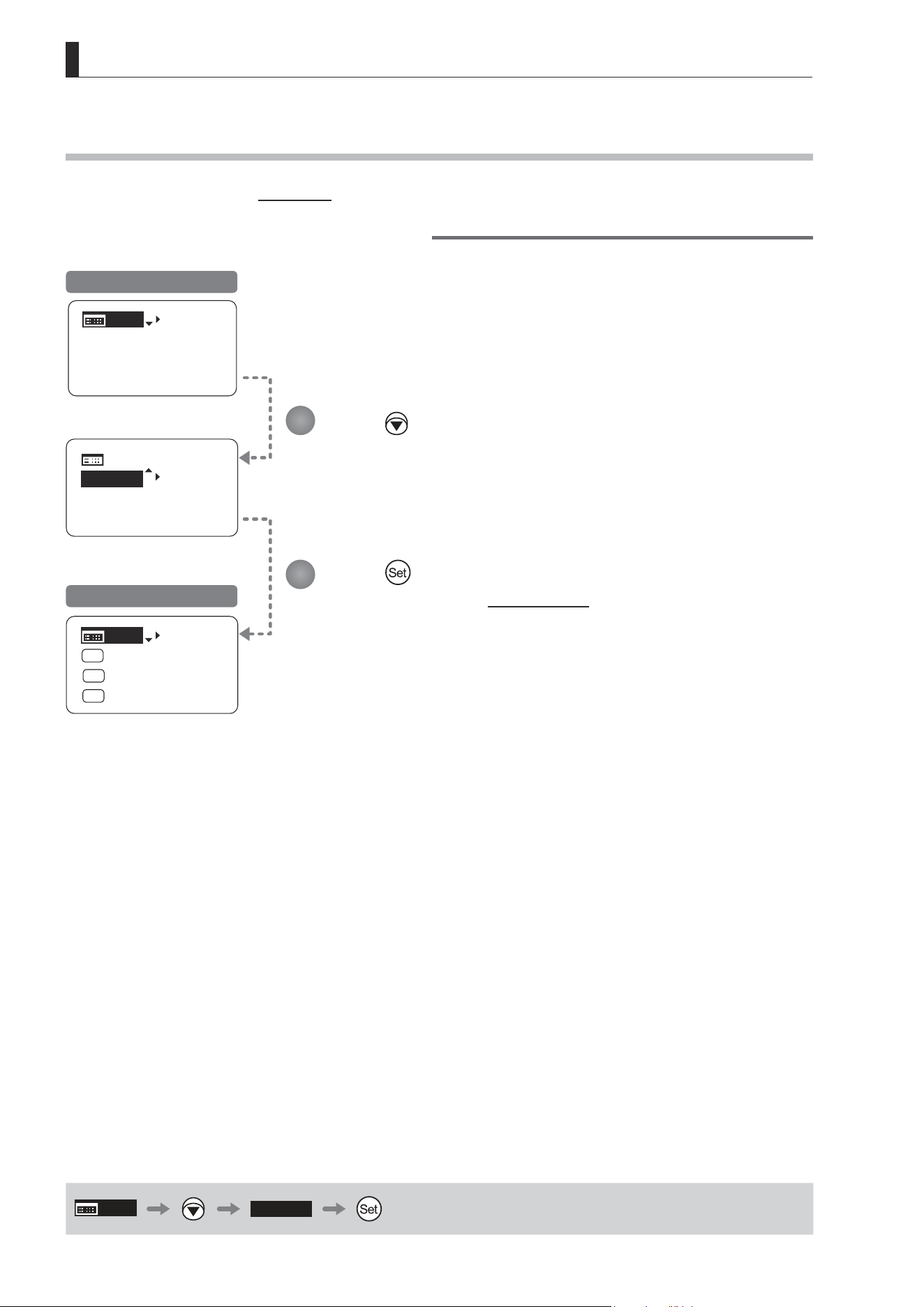
E164
5. Operation in Analog Mode
5.1.4 Switching to Basic Mode [Basic]
Switch to Basic mode from the Top screen as needed.
Switching from Analog to Basic Mode
MENU
IG: 50
[ Basic ]
MENU
MENU
[ Basic ]
IG: 50
[Trk]
OFF
Shtl
A 1
A 2
MENU
IG: 50
A
Fr1P
Fr1P
[I-Tq]H
[Adj]
Initial Top Screen in Analog Mode
Initial Top Screen in Basic Mode
MENU
[ Basic ]
Press .
The mode switches, and the Initial Top screen in Basic mode is displayed.
Press .
[Basic] is highlighted.
1
2
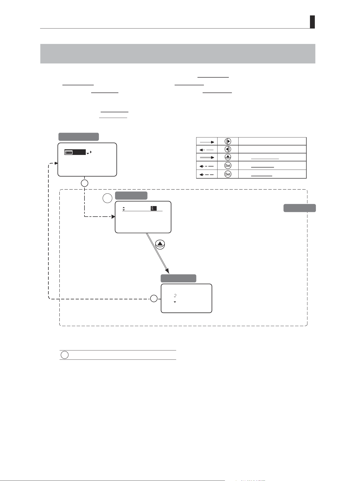
E165
5. Operation in Analog Mode
5.2 Conguration from the Menu Screen
In Analog mode, you can view and congure 2 setting items from the Menu screen.*
From the Menu screen in Analog mode, you can access a User screen.
Select [MENU] on the Top screen and press the Set key to access the User screen. (See the following gure.)
*: There is no single Menu screen. Instead, screens accessed by selecting [MENU] and pressing the Set key are collectively
referred to as the Menu screen.
: Go Top
: Back
Set
Set
1
Mode:
User
Analog
Access:
A
Unlock
MENU
IG: 50
[ Basic ]
1
User Screen................................................ 5.2.1
To the next screen clockwise
To the next screen counterclockwise
To the Go Top screen
To the User screen
To the Top screen
Initial Top Screen
User Screen
Go Top Screen
Menu Screen

E166
5. Operation in Analog Mode
5.2.1 User Screen Settings
The following setting items can be congured on the User screen.
Switching Modes
Locking Functions
Mode:
User
Analog
Access:
A
Unlock
User Screen in Analog Mode
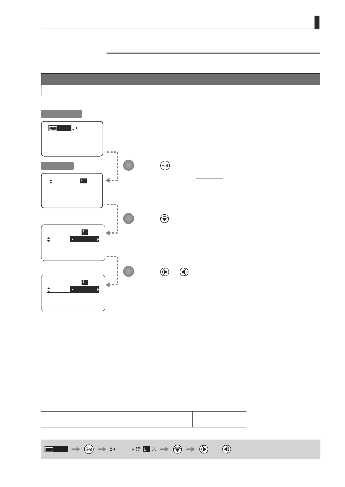
E167
5. Operation in Analog Mode
Switching Modes
Switch to Basic or Full mode, as needed.
Important
The new mode setting is retained even after the lens is turned o.
MENU
IG: 50
[ Basic ]
Mode:
User
Analog
Access:
A
Unlock
Mode:
User
Analog
Access:
A
Unlock
Mode:
User
Basic
Access:
A
Unlock
Initial Top Screen
User Screen
Press .
The display switches to the User screen.
Press .
[Mode] is underlined.
The previous mode is highlighted.
1
2
3
Press or .
Press left or right until you reach the desired mode.
Options
(D)
Basic Full Analog
Save Settings Basic Mode Full Mode Analog Mode
(D): Default value
MENU
User
A
or
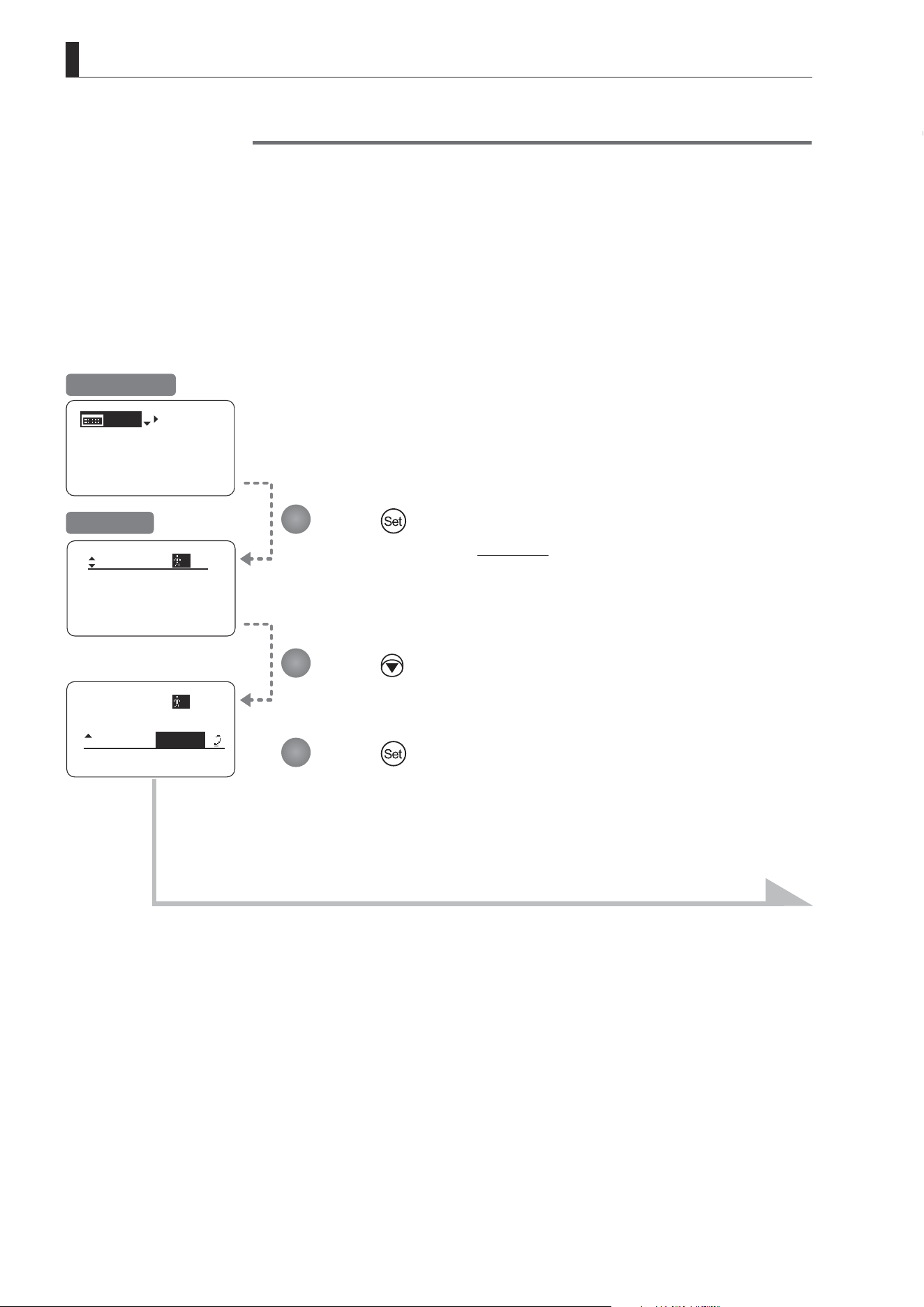
E168
5. Operation in Analog Mode
(1) Locking Settings
MENU
IG: 50
[ Basic ]
Mode:
User
Analog
Access:
A
Unlock
Access:
Unlock
Mode:
User
Analog
A
Locking Functions
To ensure that congured functions cannot easily be changed, you can lock the settings of certain functions. Once
functions are locked, they are locked for all users.
Two display operations are available in Analog mode: auto iris gain adjustment and user switching. However, you cannot
switch users when functions are locked, because this function is also locked. Unlocking functions requires the password
used to lock them.
Press .
The display switches to the User screen.
Press twice.
The previous or default value is highlighted.
Press .
Initial Top Screen
User Screen
Continued on next page
1
2
3
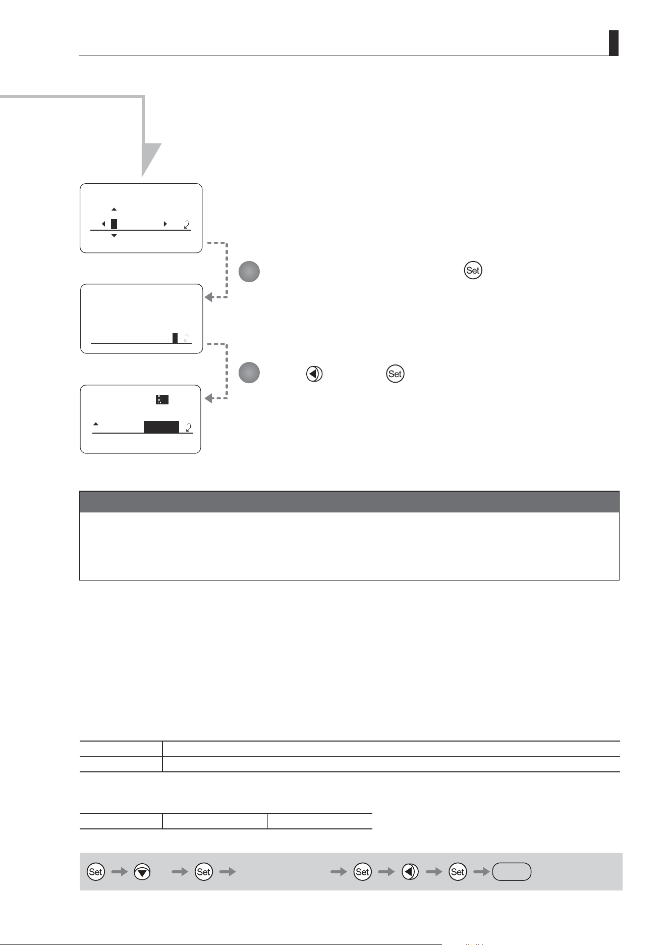
E169
5. Operation in Analog Mode
EnterPassword
EnterPassword
Lock OK?
y/n
Access:
Lock
Mode:
User
Analog
A
Enter the password and press .
Entering Passwords
Press up/down to nd characters and left/right to move the cursor or make corrections.
Be careful not to press the Set key until you are nished entering the password.
Press and then .
The settings are now locked.
Continued from previous page
Characters supported in passwords
Options
(D)
_– A B C D E F G H I J K L M N O P Q R S T U V W X Y Z a b c d e f g h i j k l m n o p q r s t u v w x y z 0 1 2 3 4 5 6 7 8 9
Max. Digits 8
(D) : Default value
_ : Space
Options
(D)
Unlock Lock
(D): Default value
× 2 Entering Passwords
DISPLAY
4
5
Note
Passwords
No master password is used on this model. The password you enter each time to lock settings is the password used
to unlock them. For this reason, we recommend making a note of the password each time. If you forget the password,
contact Canon or your dealer. Passwords can be blank or up to 8 digits.
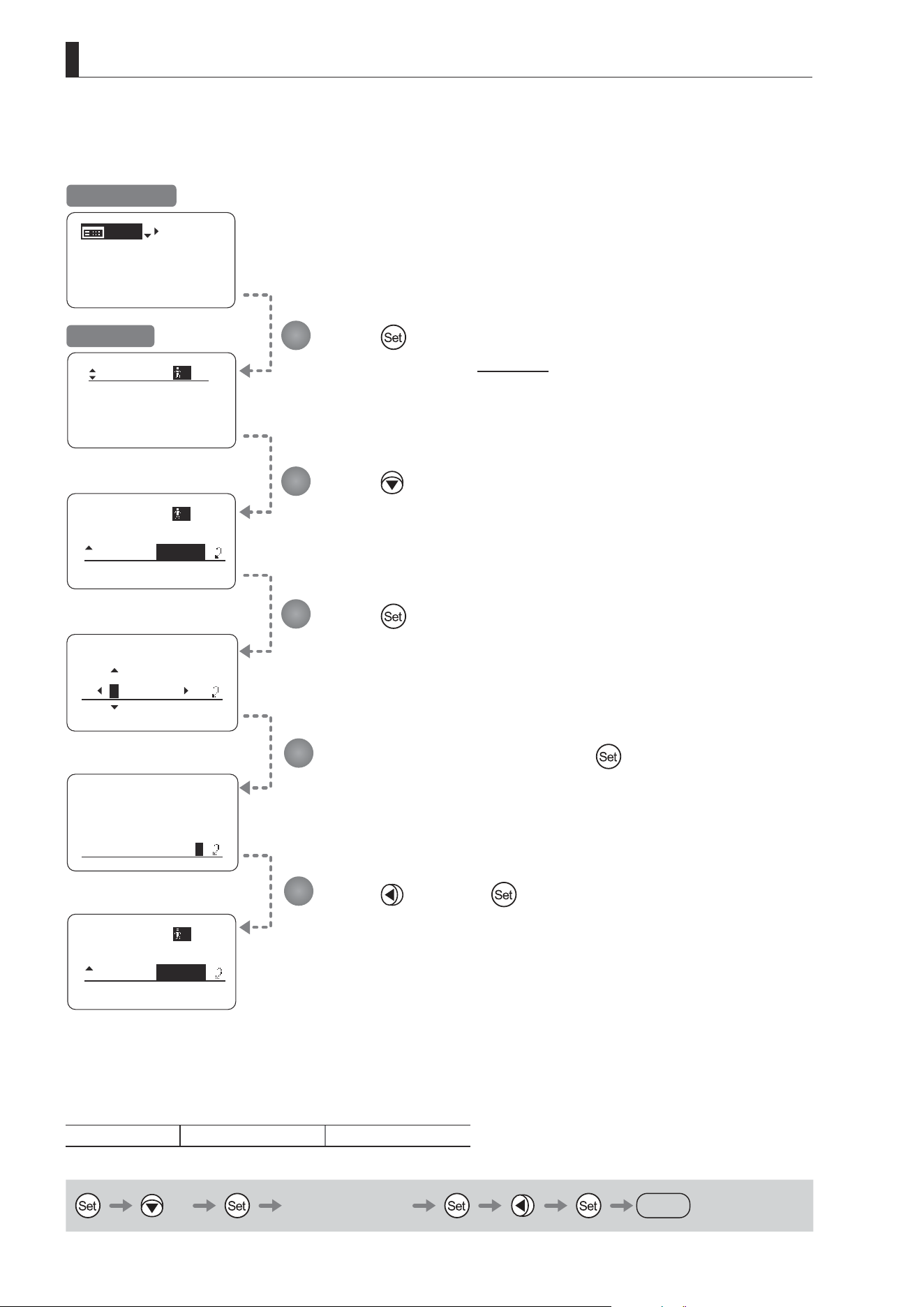
E170
5. Operation in Analog Mode
MENU
IG: 50
[ Basic ]
Mode:
User
Analog
Access:
A
Lock
Access:
Lock
Mode:
User
Analog
A
EnterPassword
EnterPassword
Unlock OK?
y/n
Access:
Unlock
Mode:
User
Analog
A
(2) Unlocking Settings
4
5
Press .
The display switches to the User screen.
Press twice.
The previous or default value is highlighted.
Enter the password and press .
Entering Passwords
Press up/down to nd characters and left/right to move the cursor or make corrections.
Be careful not to press the Set key until you are nished entering the password.
Press .
Press
and then .
The settings are now unlocked.
Options
(D)
Unlock Lock
(D): Default value
× 2 Entering Passwords
DISPLAY
Initial Top Screen
User Screen
1
2
3
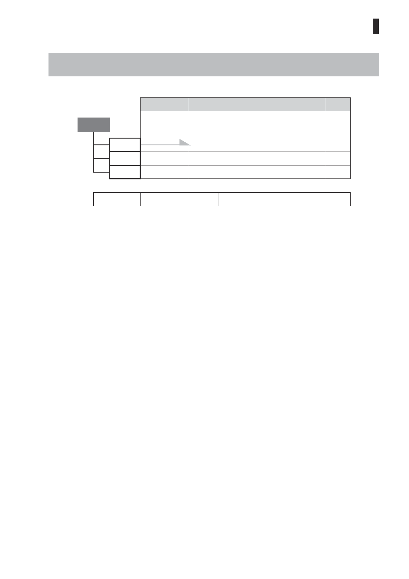
E171
5. Operation in Analog Mode
5.3 List of Settings
Default Value Options Page
Top
MENU To *1 on the next page
IG 50 01–99
[Basic] Basic
Escape Operation Jump to user 0 setting status
Hold down both the Display switch and Set key
for at least 2 seconds.
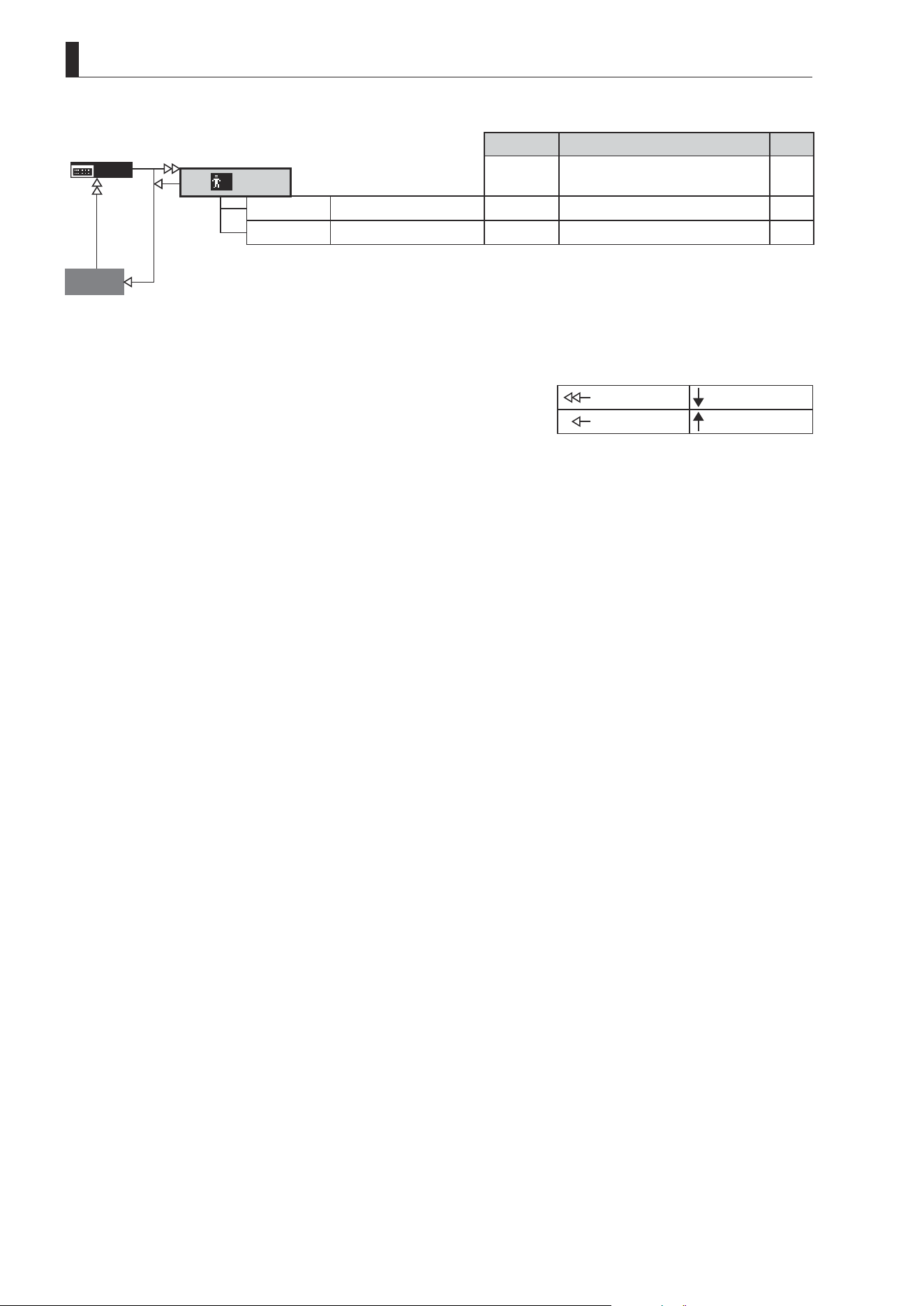
E172
5. Operation in Analog Mode
Default Value
Options Page
MENU
User
*
*1
Mode
Basic Basic / Analog / Full
Access Unlock Unlock / Lock
Go Top
: Set key operation : Right key operation
: Up key operation : Left key operation

Memo

CANON INC.
30-2, Shimomaruko 3-chome, Ohta-ku, Tokyo, 146-8501, Japan
BT1-D008-A-ENG ©2022.09 CANON INC.
