
IWR-2458-AC-S-I
Configuration
Manual
Beijing Nodes Network Limited
2025

Configuration Manual-IWR-2458-AC-S-I
1
Contents
1. Introduction ........................................................................................... 2
Overview ............................................................................................2
Power Supply .....................................................................................3
2. First-time Configuration .........................................................................4
3. Operation Mode .................................................................................... 5
3.1 Client Mode ..................................................................................6
Wireless-Radio setup ..................................................................6
WLAN Security Settings ............................................................. 8
Network Setup .......................................................................... 11
Communication Log Setting ......................................................14
Connection Info .........................................................................15
3.2 AP Mode .................................................................................... 16
WLAN Setup ............................................................................. 16
Network Setup .......................................................................... 18
Communication Log Setting ......................................................19
Association List .........................................................................20
4. Maintenance ....................................................................................... 21
Log Download ..................................................................................21
Change Password ........................................................................... 21
Configuration Import and Export ...................................................... 21
Firmware Update ............................................................................. 23
Load Factory Default ........................................................................24
Configuration Manual-IWR-2458-AC-S-I
2
1. Introduction
IWR-2458-AC-S-I is an industrial dual-band equipment, which provides users
with an unparalleled WiFi experience and highly reliable wireless connection by
adding a number of powerful functions to meet the challenges in the WiFi
deployment of the industrial field.
It can be operated on the 2.4 and 5 GHz simultaneously, and supports profinet
& modbus protocols. It is built-in advanced interference suppression functional
components which can significantly reduce wireless interference in noisy
industrial applications.
Overview
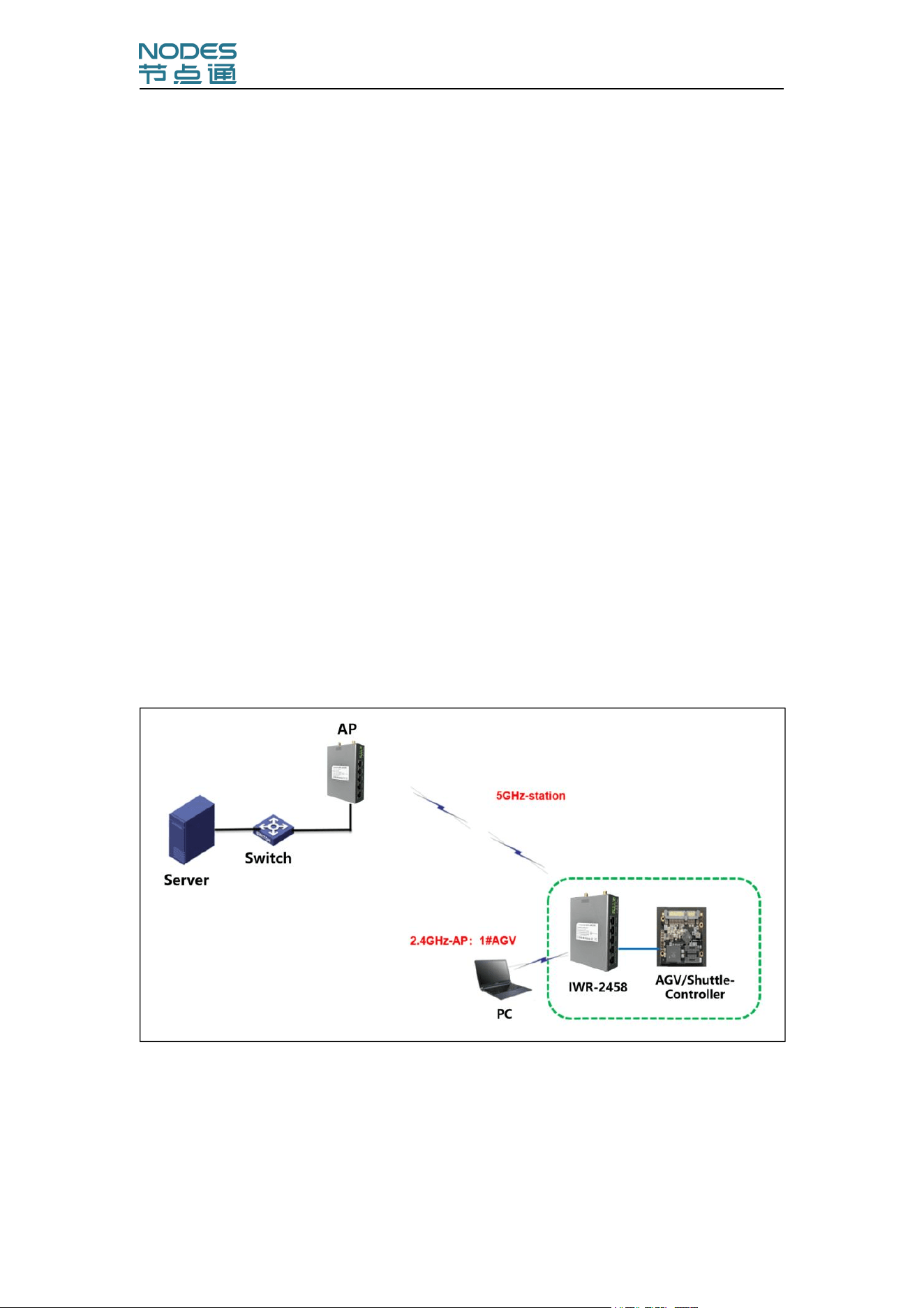
The IWR-2458-AC-S-I can be used as a dual-band wireless AP to provide WiFi
coverage, It can also be used as a wireless client, installed on mobile devices
such as AGV/RGV. You can change the work mode to adapt your applications,
such as AP/Station/Repeater.
Configuration Manual-IWR-2458-AC-S-I
3
Power Supply
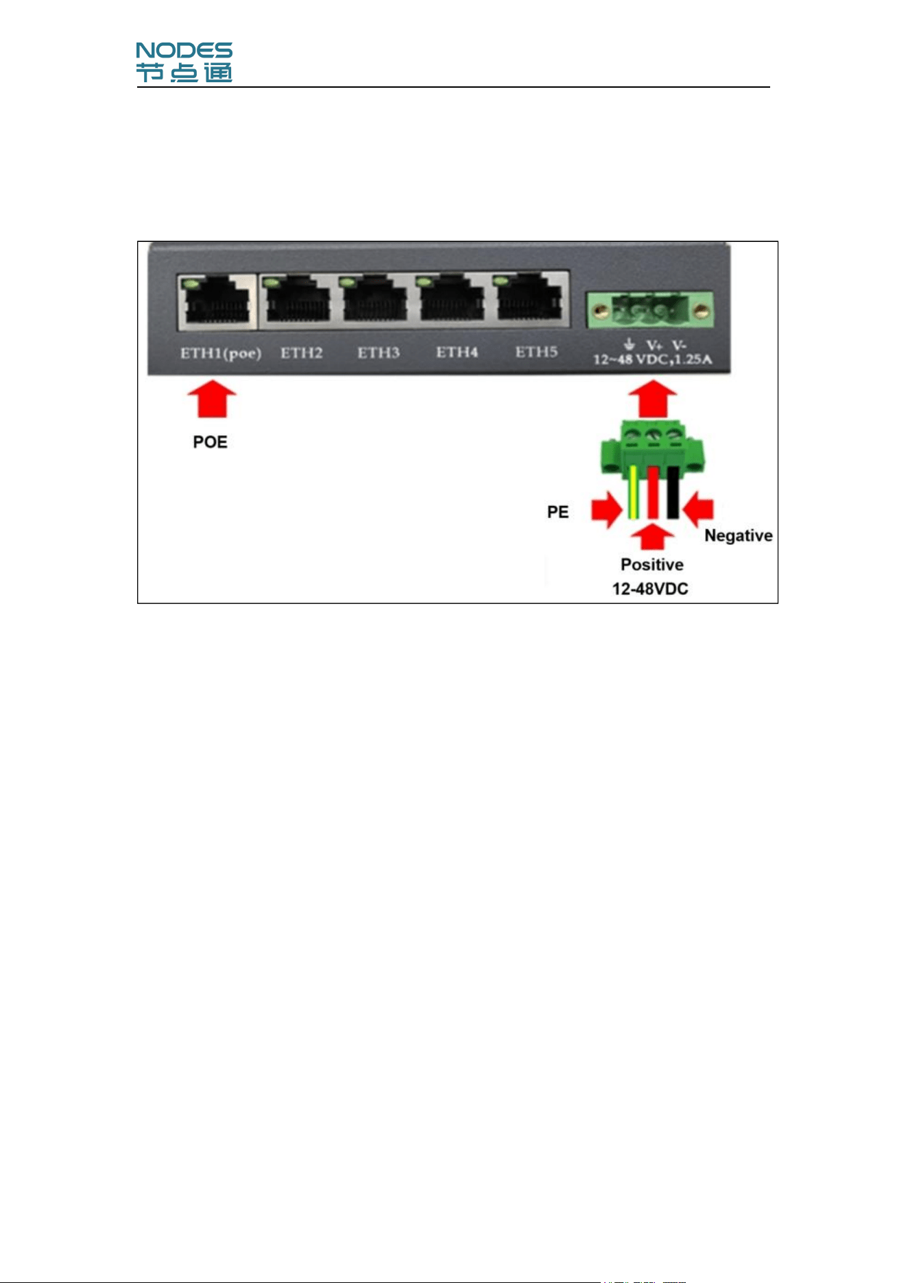
The IWR-2458-AC-S-I supports 12-48V DC power supply,the schematic
diagram is as follows:
Configuration Manual-IWR-2458-AC-S-I
4
2. First-time Configuration
Before configuration the CPE-2458, you will need access to a PC equipped
with an Ethernet port. The CPE-2458 has a default IP address that must be
used when connecting to the device for the first time.
Step 1: Connect a power source.
The CPE-2458 can be powered by a DC(12-48v) power input.
Step 2: Connect the CPE-2458 to PC.
You can use a straight-through cable to connect the CPE-2458 to PC. The
LED indicator on the CPE-2458’s LAN port will light up when a connection is
established.
Step 3: Set up the computer’s IP address.
Choose an IP address on the same subnet as the CPE-2458. Since the CPE-
2458’s default IP address is 192.168.1.222, and the subnet mask is
255.255.255.0, you should set the IP address of the computer to 192.168.1.x.
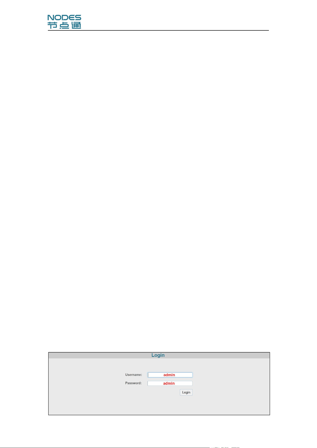
Step 4: Use the web-based manager to configure the CPE-2458
Open your computer’s web browser and type http://192.168.1.222 in the
address field to access the homepage of the web-based Network Manager.
Before the homepage opens, you will need to enter the Username and
Password as shown in the following figure. For first-time configuration, enter
the default username and password and then click on the Login button.
Configuration Manual-IWR-2458-AC-S-I
5
3. Operation Mode
The CPE-2458 supports four operation modes—AP, Station, Repeater, and
Bridge—each of which plays a distinct role in a wireless network.
Enable Radio
Setting
Description
Factory Default
Enable Radio
Use this function to turn the RF (Radio
Frequency) module on or off.manually.
Enable
Operation mode
Setting
Description
Factory Default
AP
CPE-2458 plays the role of wireless access point
2.4GHz-AP
5GHz-Station
Station
CPE-2458 plays the role of wireless client
Repeater
CPE-245 can not only provide a backhaul link as a
client but also offer signal coverage as an AP
Bridge
CPE-245 plays the role of Point To Point link

Configuration Manual-IWR-2458-AC-S-I
6
3.1 Client Mode
Wireless-Radio setup
The Wireless-Radio panel is used to edit the SSIDs and set the RF type
for the device. You can choose the Radio0 or Radio1 to configure the CPE-
2458 to operate either on the 2.4 GHz or 5 GHz frequency band. An SSID is a
unique identifier that wireless networking devices use to establish and
maintain wireless connectivity. Set the SSID of CPE-2458 to match with the
SSID of the AP that you want it to connect to, so that the CPE-2458 will
associate with the network defined by the SSID.
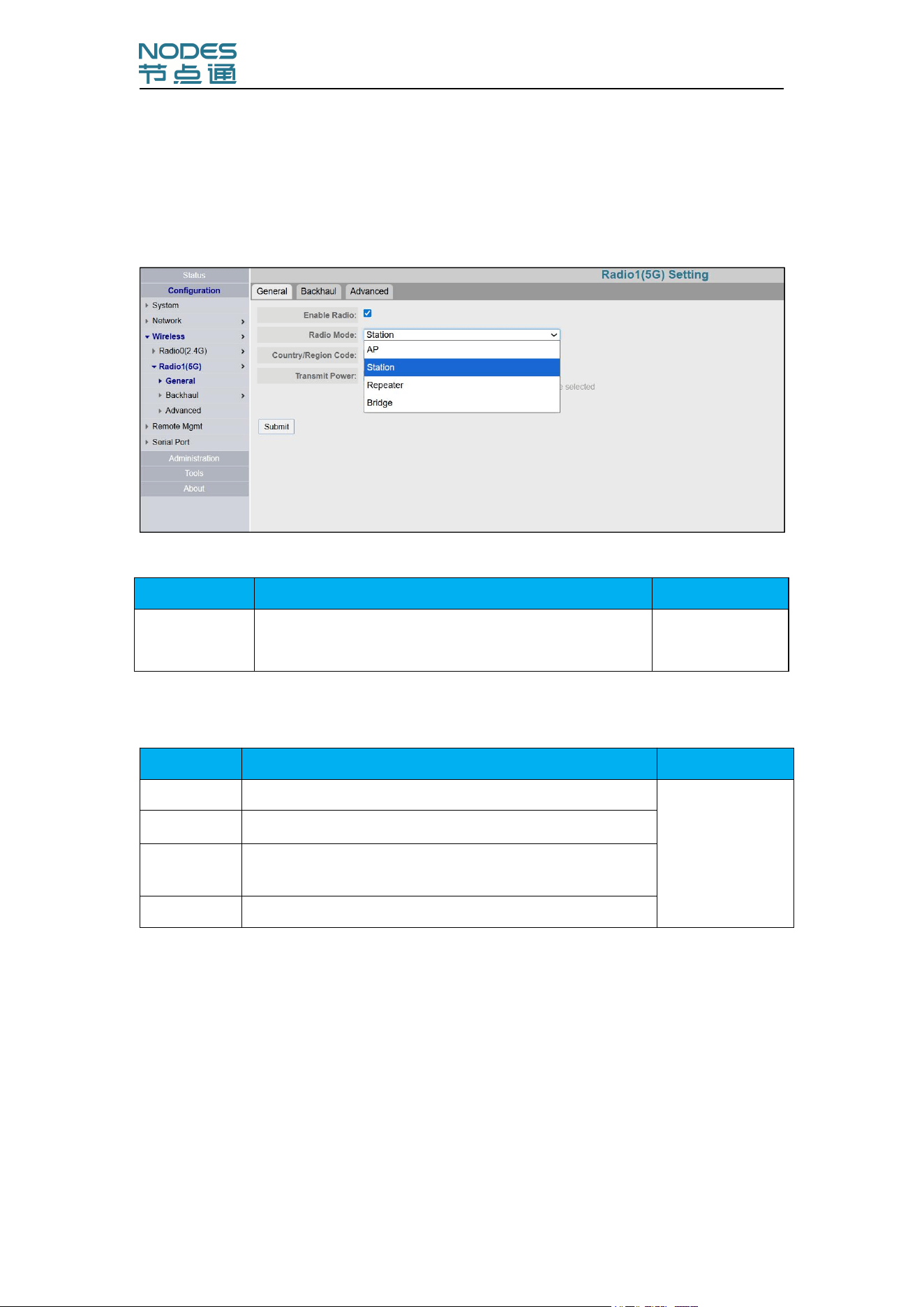
Click in sequence, "Configuration→Wireless→Radio1(5G)→General" to enter
the following configuration interface:
Enable Radio:The RF (Radio Frequency) module can be manually turned
on or off. When you check it ,the RF turns on.
Radio Mode:Station
Transmit Power:Click on the options bar.Scroll down to the bottom and
select the maximum value
Click Submit
Configuration Manual-IWR-2458-AC-S-I
7
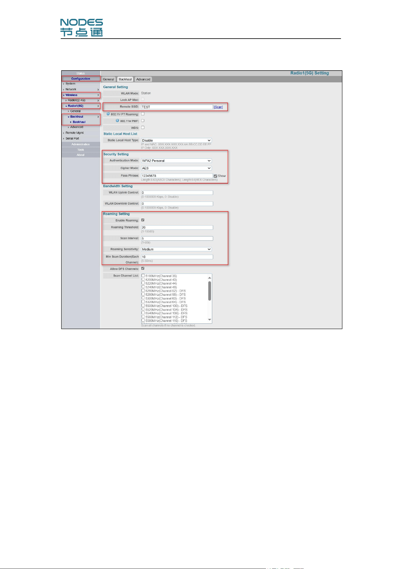
Click on "Backhaul" to enter the following basic configuration interface:
Remote SSID: Fill in the SSID (you can scan and select
)
Authentication Mode: Select the corresponding mode
Cipher Mode: Select the corresponding mode
Pass Phrase: Fill in the connection password
Enable Roaming:check
Roaming Threshold:20
Roaming Sensitivity: Medium
Allow DFS Channels: Check .(To ensure that the device supports 5GHz full
frequency band)
Scan Channel List: No need to check
Click Submit
Configuration Manual-IWR-2458-AC-S-I
8
WLAN Security Settings
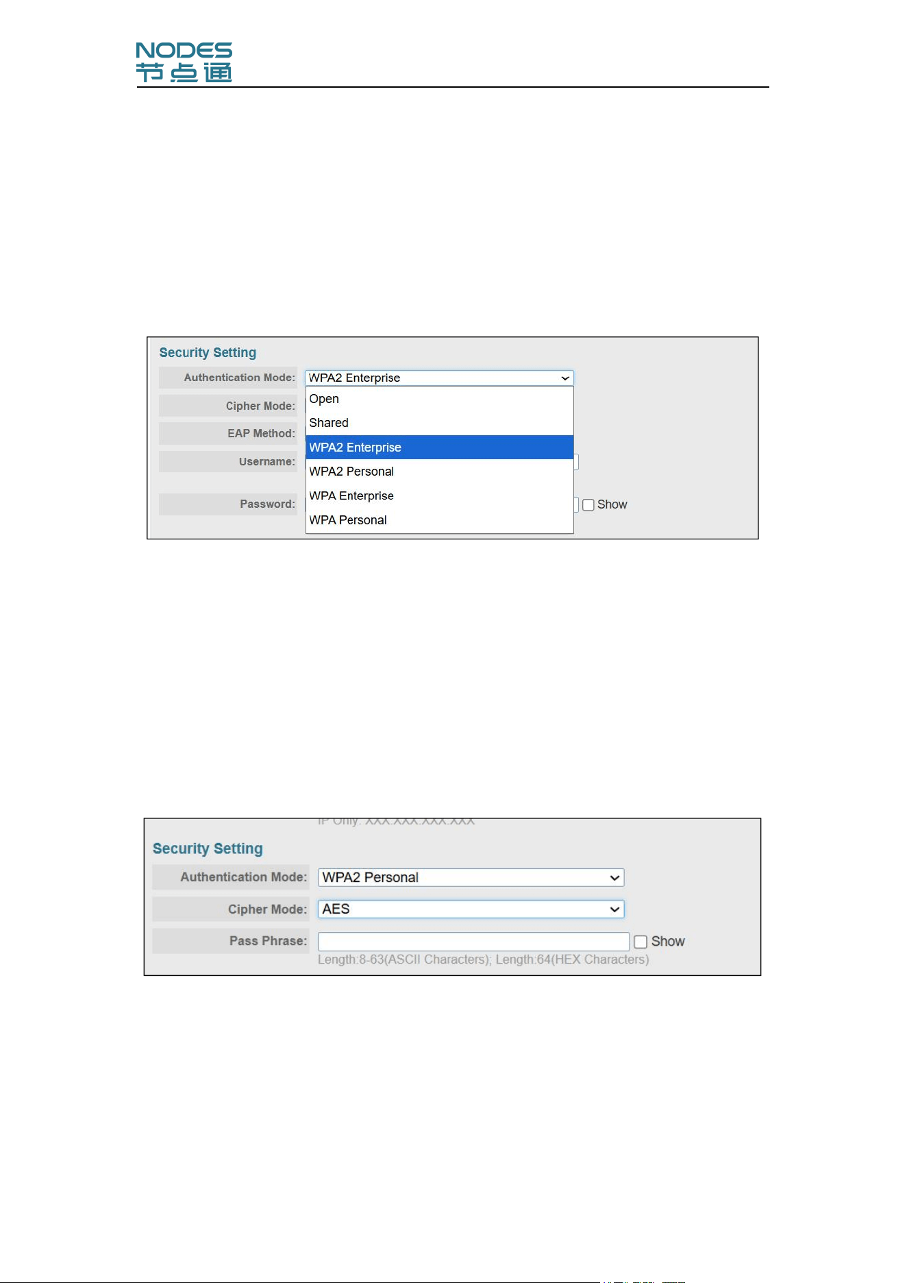
The CPE-2458 provides four standardized wireless security modes: Open,
Shared(Shared Key), WPA (Wi-Fi Protected Access), and WPA2. Several
security modes are available in the CPE-2458 by selecting Security mode and
WPA type:
WPA/WPA2 Personal :
Personal versions of WPA/WPA2, also known as WPA/WPA-PSK (Pre-Shared
Key), provide a simple way of encrypting a wireless connection for high
confidentiality. A Passphrase is used as a basis for encryption methods (or
cipher types) in a WLAN connection. The passphrases should be complicated
and as long as possible. For security reasons, this passphrase should only be
disclosed to users who need it, and it should be changed regularly.
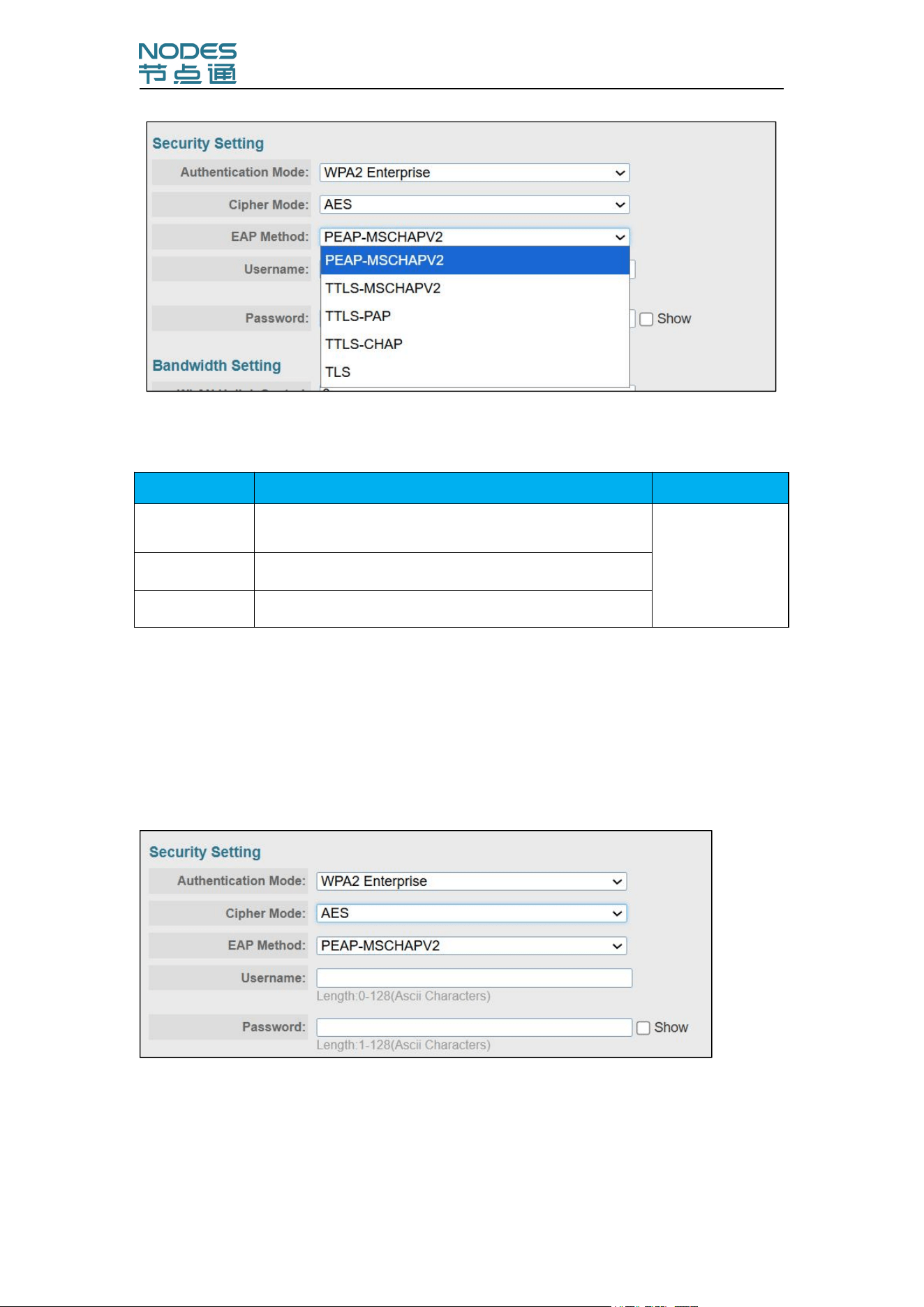
WPA/WPA2 Enterprise :
When used as a client, the CPE-2458 can support three EAP methods (or
EAP protocols): EAP-TLS, EAP-TTLS, and EAP-PEAP, corresponding to
WPA/WPA-Enterprise settings on the AP side.
Configuration Manual-IWR-2458-AC-S-I
9
EAP Protocol
Setting
Description
Factory Default
PEAP
Specifies Protected Extensible Authentication
Protocol, or Protected EAP
PEAP
TTLS
Specifies Tunneled Transport Layer Security
TLS
Specifies Transport Layer Security protocol
Before choosing the EAP protocol for your WPA/WPA2-Enterpise settings on
the client end, please contact the network administrator to make sure the
system supports the protocol on the AP end. Detailed information on these
three popular EAP protocols is presented in the following sections.
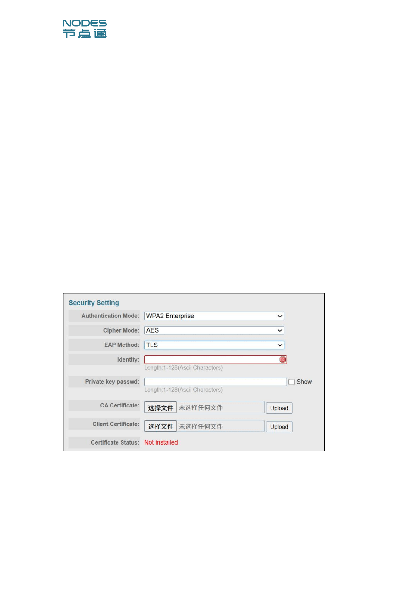
PEAP&TTLS:
TTLS and PEAP work in a similar way. First, they establish a TLS tunnel
(EAP-TLS for example), and validate whether the network is trustworthy with
digital certificates on the authentication server. This step establishes a tunnel
that protects the next step (or “inner”authentication), and consequently is
Configuration Manual-IWR-2458-AC-S-I
10
sometimes referred to as “outer” authentication. The TLS tunnel is then used
to encrypt an older authentication protocol that authenticates the user for the
network.
As you can see, digital certificates are still needed for outer authentication in a
simplified form. Only a small number of certificates are required, which can be
generated by a small certificate authority. Certificate reduction makes TTLS
and PEAP much more popular than EAP-TLS.
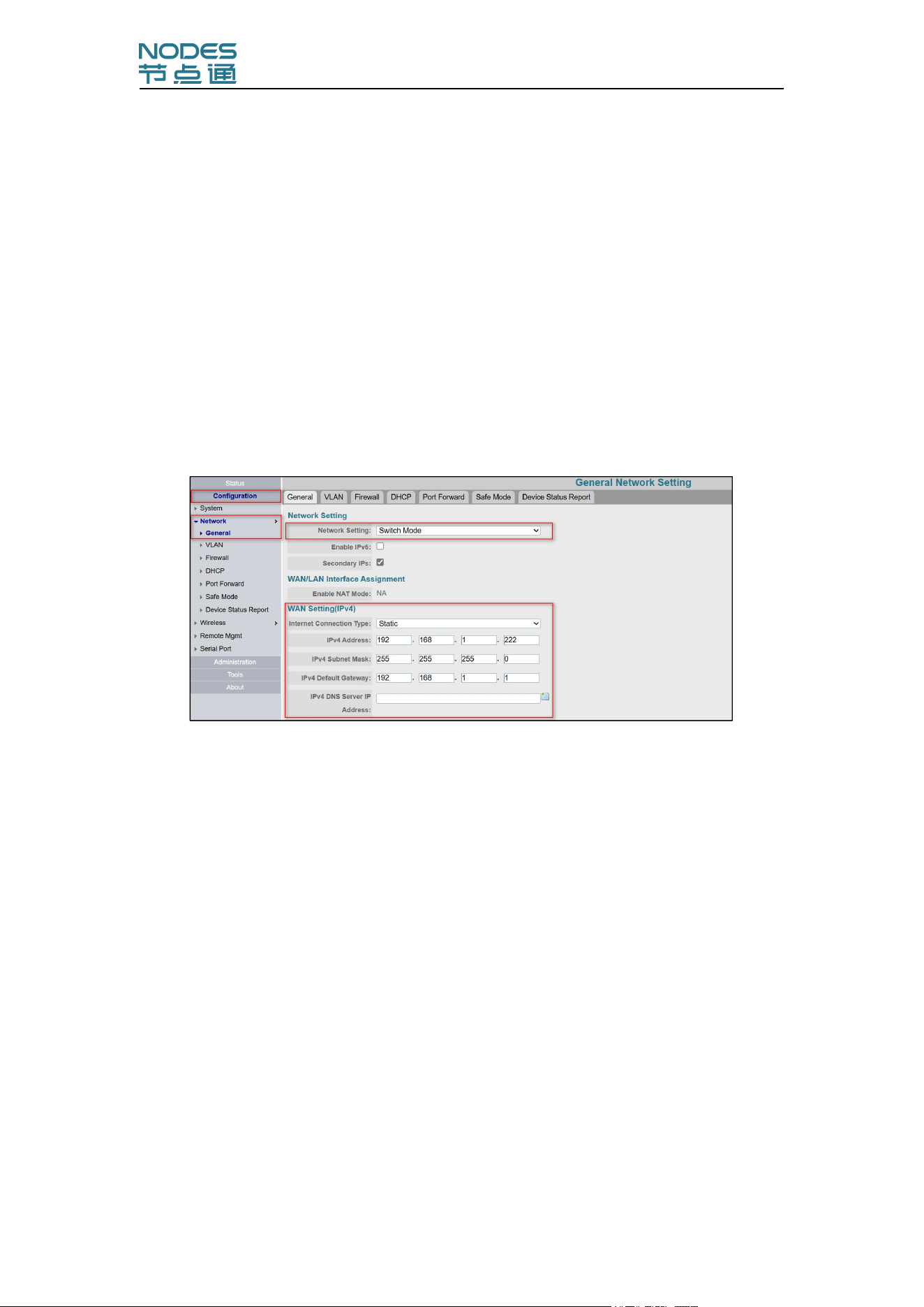
TLS:
TLS is the standards-based successor to Secure Socket Layer (SSL). It can
establish a trusted communication channel over a distrusted network. TLS
provides mutual authentication through certificate exchange.
EAP-TLS is also secure to use. You are required to submit a digital certificate
to the authentication server for validation, but the authentication server must
also supply a certificate.
Configuration Manual-IWR-2458-AC-S-I
11
Network Setup
The network mode includes:
①Switch Mode
②Gateway Mode
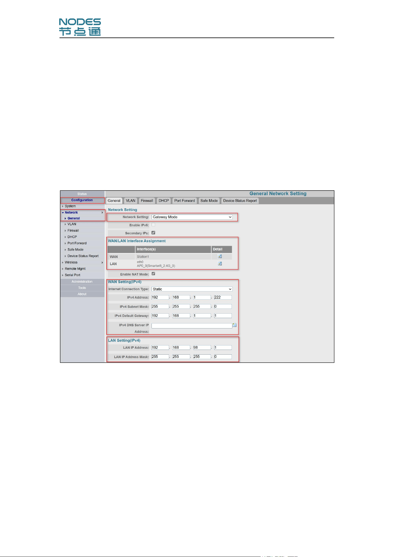
Switch Mode:
Adapt to the Nodes AP and other fat AP , in which the CPE module and AGV
controller use the same network segment IP.(Each AGV will occupy multiple IP
addresses, making it more suitable for self-organizing LAN environments)
Click on "Configuration→Network→General":
Network Setting:Switch Mode
Static IP address modification:
Fill in the IP address, subnet mask, and gateway
Choose whether to modify the DNS server based on the project
Click Summit
Dynamic IP address modification:
Internet connection type:DHCP
Click Submit
Configuration Manual-IWR-2458-AC-S-I
12
Gateway Mode:
If you need to access to fit AP,and the number of IP addresses is limited, CPE
can use gateway mode.Each AGV/RGV only occupies one IP address, and the
controller’s configuration is simple and unified.
Due to the better compatibility and adaptability of the gateway mode, we
strongly recommend to use gateway mode!
Click in sequence, "Configuration→Network→General" to enter the following
configuration interface:
Network Setting:Gateway Mode
WAN/LAN Interface Assignment:
Station interface as WAN port;
eth0 and others as LAN port
WLAN Setting (IPv4):
Internet Connection Type:Static/DHCP
Fill in the planned IP address, subnet mask, and gateway
Choose whether to modify the DNS server based on the project
Configuration Manual-IWR-2458-AC-S-I
13
Click Submit
LAN Setting(IPv4):
Click to submit the IP address and subnet mask planned for the device
LAN-IPv4 serves as the management IP for the LAN port of the device
and the gateway for the backend controller.
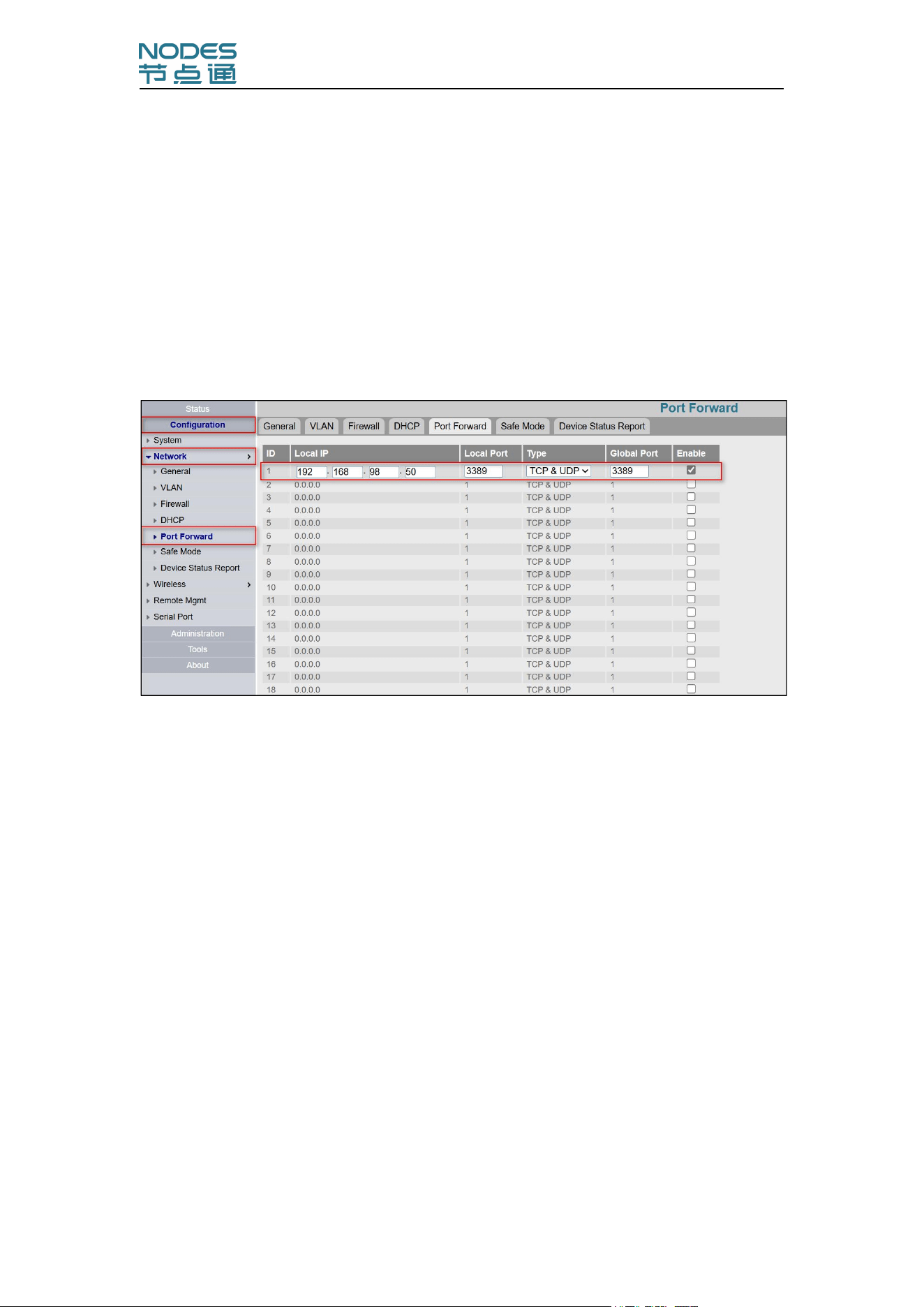
Port Forward:
Click on "Port Forwarding" :
Check to enable port
Local IP:Fill in the IP address of the AGV/RGV controller
Local Port and Global Port:The communication port used by controller
Type:TCP or UDP,TCP&UDP
Click Submit
Configuration Manual-IWR-2458-AC-S-I
14
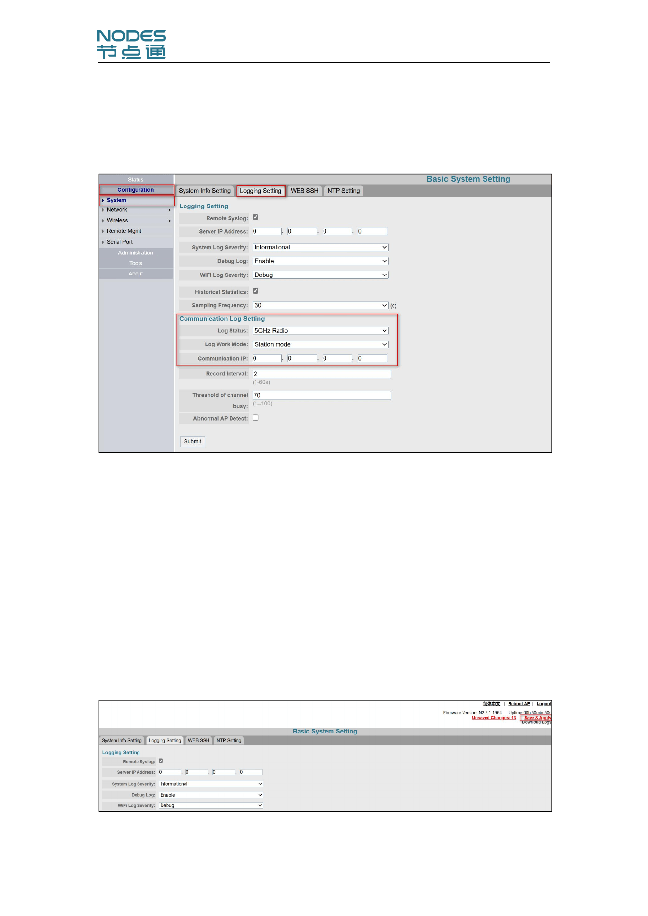
Communication Log Setting
Click in sequence,"Configuration→System→Logging Setting" to enter the
following interface:
Log Status:5GHz RF/2.4GHz RF(Choose the band of station mode)
Log Work Mode:Station mode
Communication IP:Server of AGV or gateway(Server is better)
Record Interval:3
Click Submit
Save Application
Click on "Save&Apply" in the upper right corner of the page, it will reboot,and
the configurations take effect.
Attention:Please use the new IP address to login again.
Configuration Manual-IWR-2458-AC-S-I
15
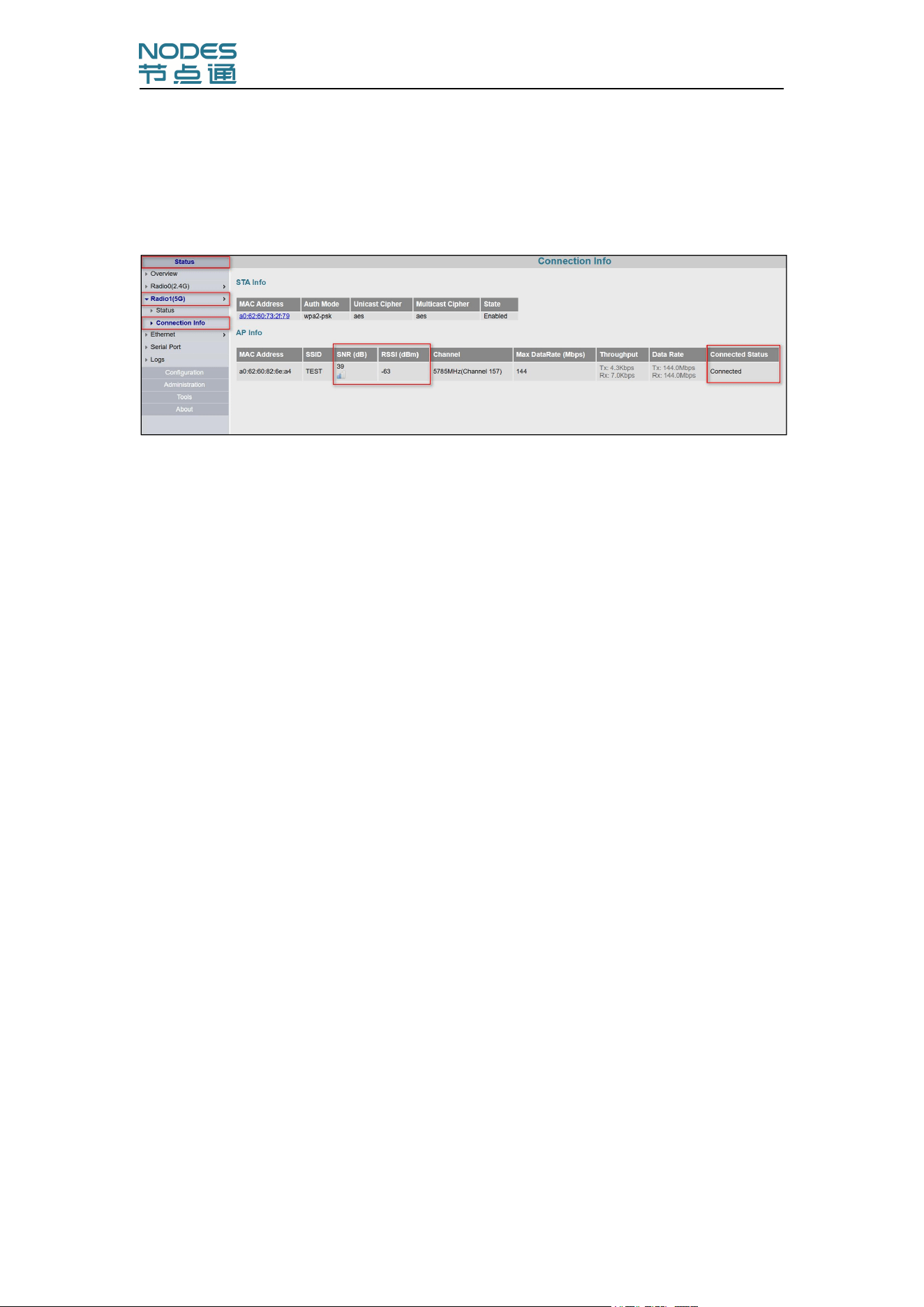
Connection Info
Click in sequence,"Status→Radio1(5G)→Connection Information" to enter the
following interface:
Connected Status:Connected
SNR(dB):39
RSSI(dBm):-63
Configuration Manual-IWR-2458-AC-S-I
16
3.2 AP Mode
WLAN Setup
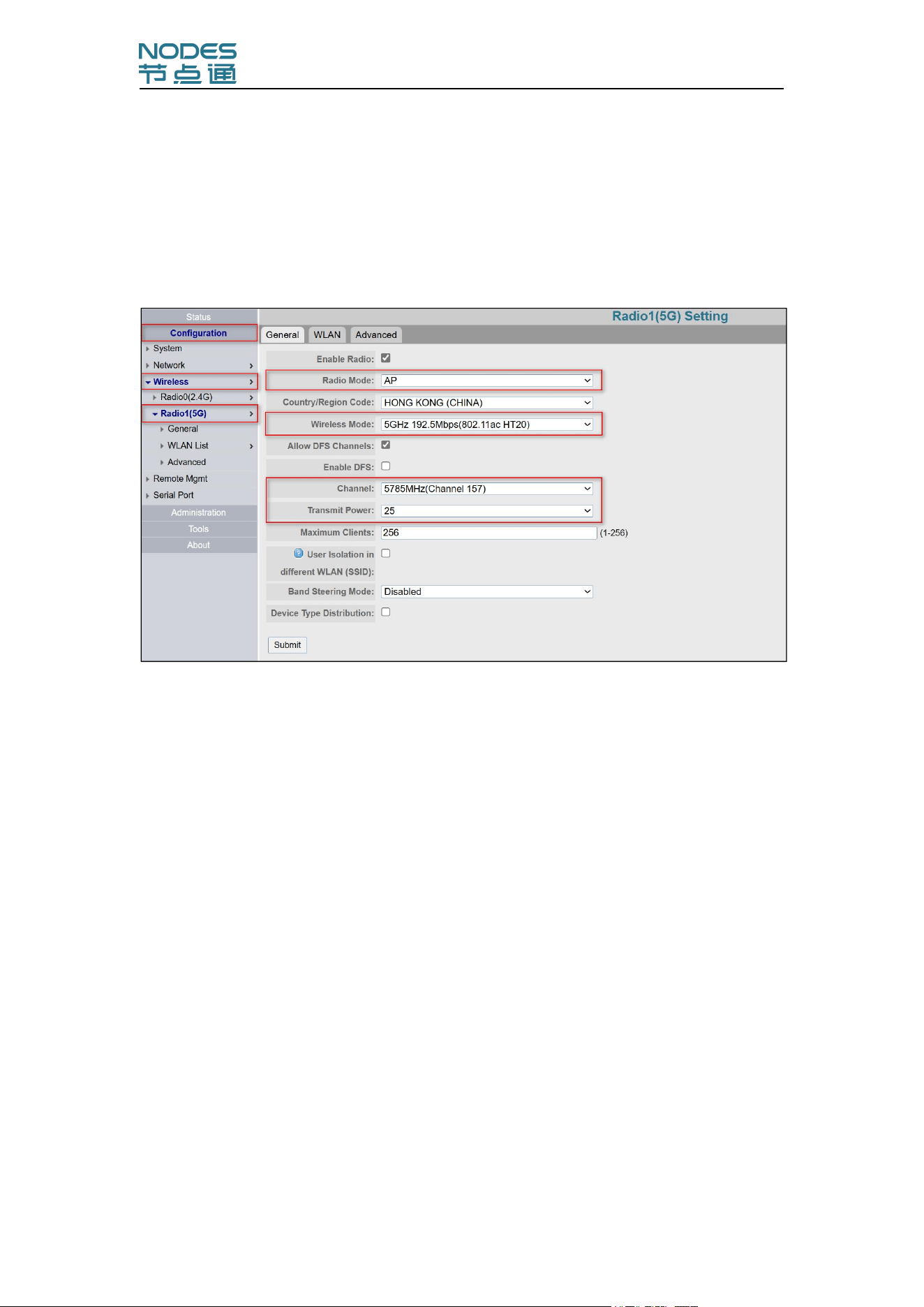
Click in sequence,"Configuration→Wireless→Radio1(5G)→Basic Information"
to enter the following configuration interface:
Radio Mode:AP
Wireless Mode:802.11ac HT20
Channel:Select based on the project site network planning(Recommend
using high-frequency channels 149~165)
Transmit Power:Click on the options bar, scroll down to the bottom, and
select the one with the highest value
Click Submit
Configuration Manual-IWR-2458-AC-S-I
17
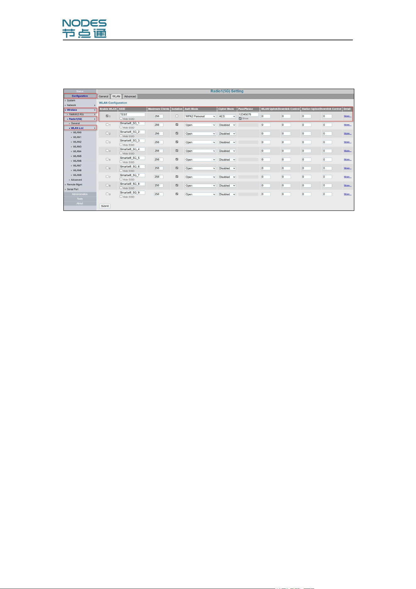
Click in sequence, "Configuration→Wireless→Radio1(5G)→WLAN" to enter
the following configuration interface:
Enable WLAN:Check to activate the corresponding SSID, multiple SSIDs
can be checked
SSID:Fill in the SSID name according to the project
Isolation:Uncheck
Auth Mode:Select what you need
Cipher Mode:Select the corresponding mode
PassPhrase:Fill in the password
Click Submit
Configuration Manual-IWR-2458-AC-S-I
18
Network Setup
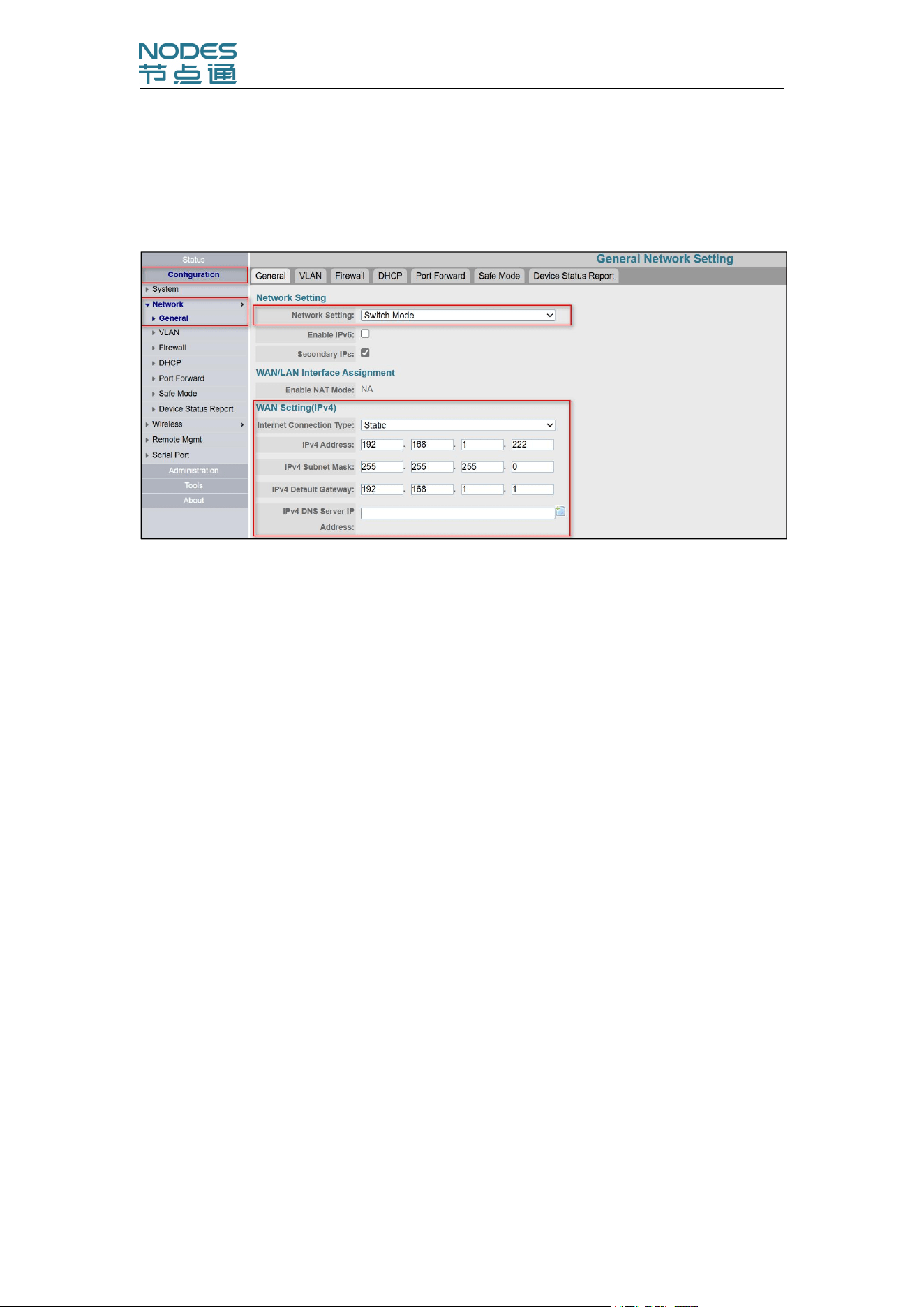
Click in sequence,"Configuration→Network→General" to enter the following
configuration interface:
Network Mode:Switch Mode
Static IP address modification:
Fill in the IP address, subnet mask, and gateway
Choose whether to modify the DNS server based on the project
Click Summit
Dynamic IP address modification:
Internet connection type:DHCP
Click Submit
Configuration Manual-IWR-2458-AC-S-I
19
Communication Log Setting
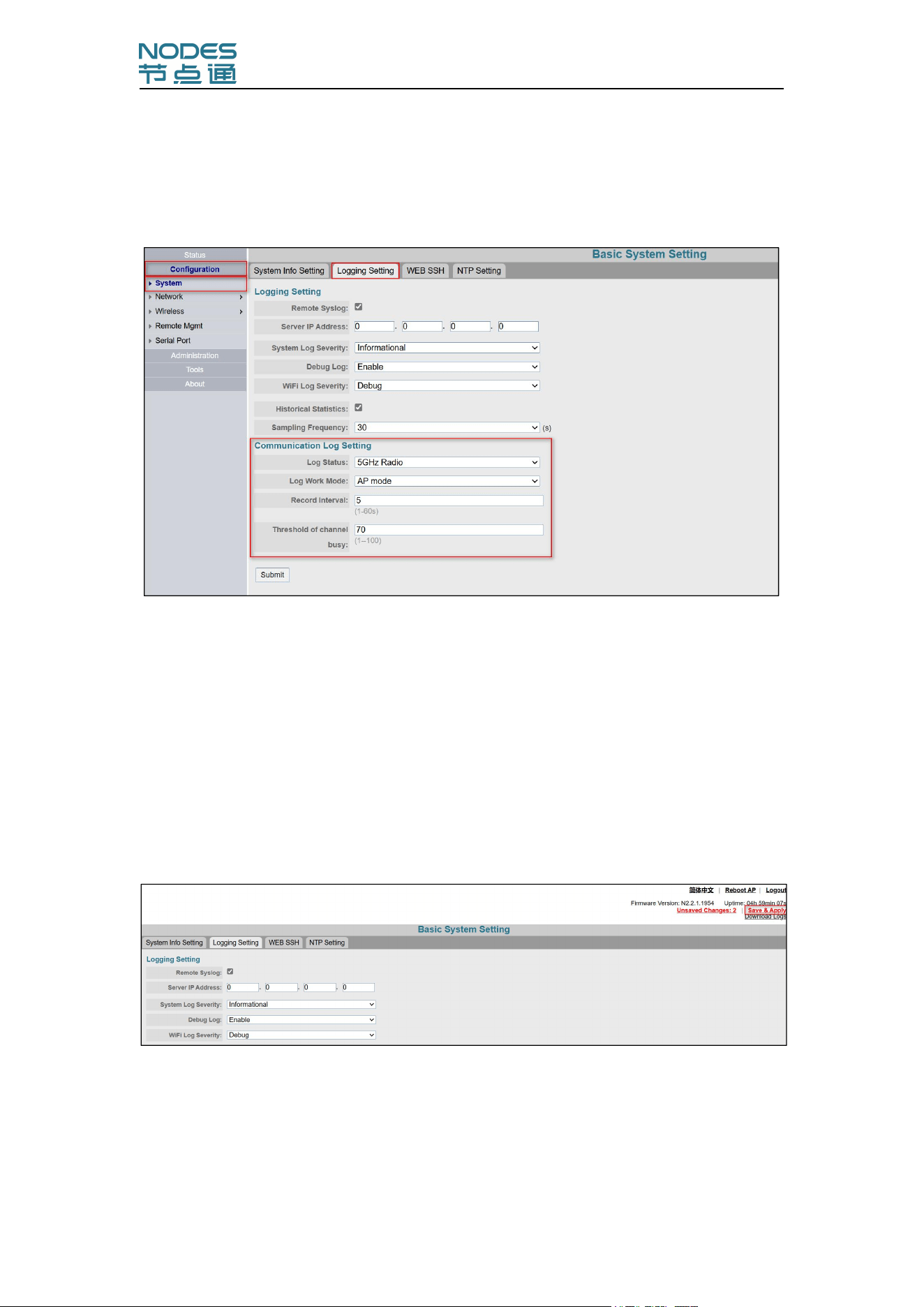
Click in sequence,"Configuration→System→Logging Setting" to enter the
following configuration interface:
Log States:5GHz RF/2.4GHz RF(Choose the band of AP mode)
Log Work Mode:AP mode
Record Interval:5
Click Submit
Save Application
Click on "Save&Apply" in the upper right corner of the page, it will reboot,and
the configurations take effect.
Attention:Please use the new IP address to login again.
Configuration Manual-IWR-2458-AC-S-I
20
Association List
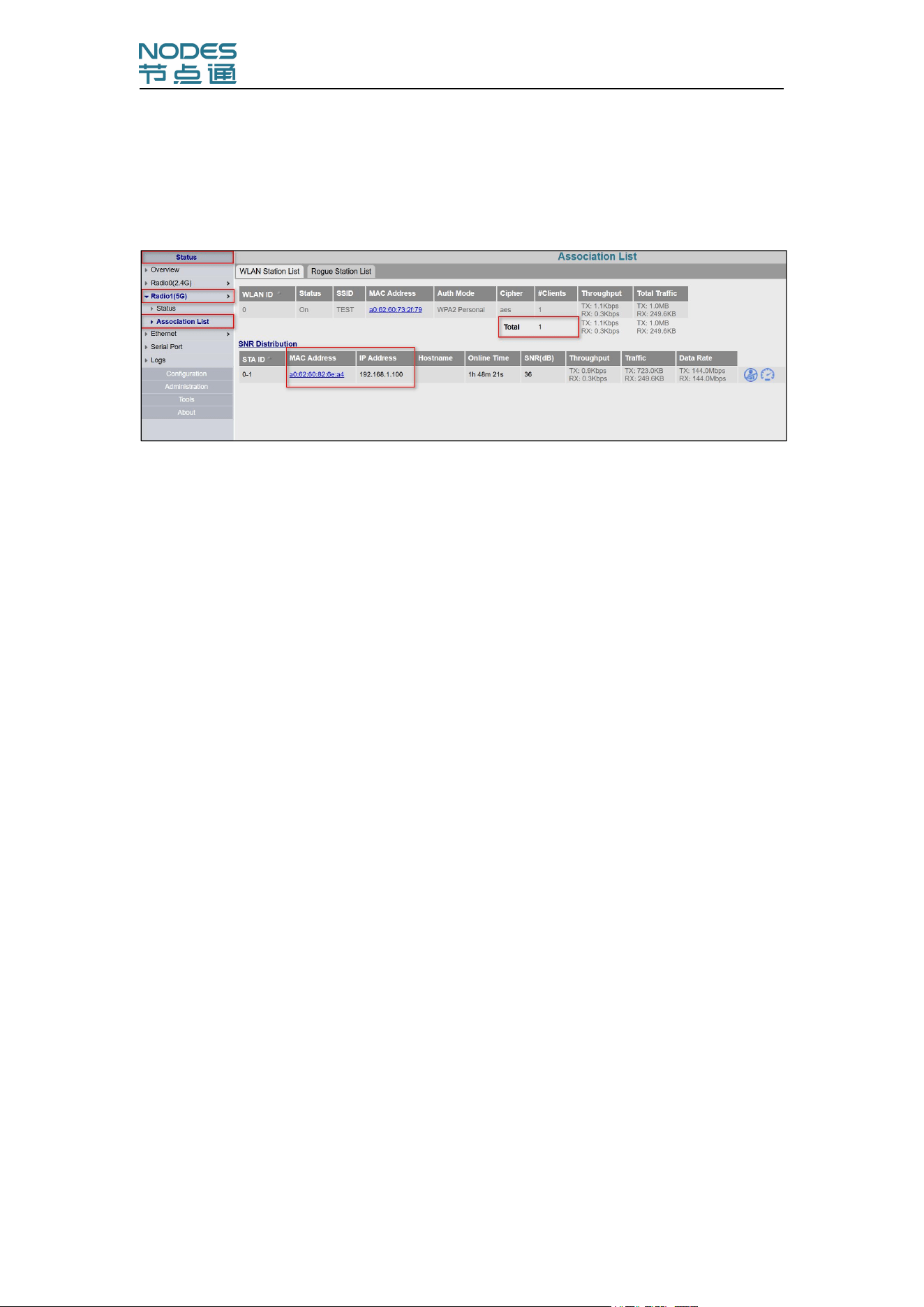
Click in sequence,"Status→Radio1(5G)→Association List" to enter the
following interface:
Total number of connections:1
Access terminal MAC/IP/SNR/Data Rate
Configuration Manual-IWR-2458-AC-S-I
21
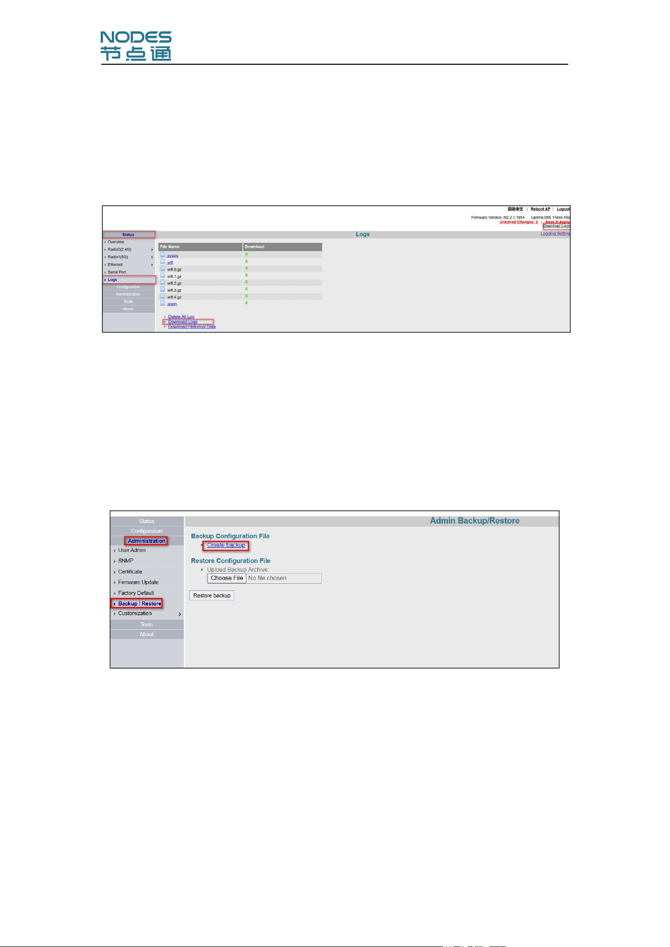
4. Maintenance
Log Download
Click on "Download Logs" in the upper right corner of the device interface.
Change Password
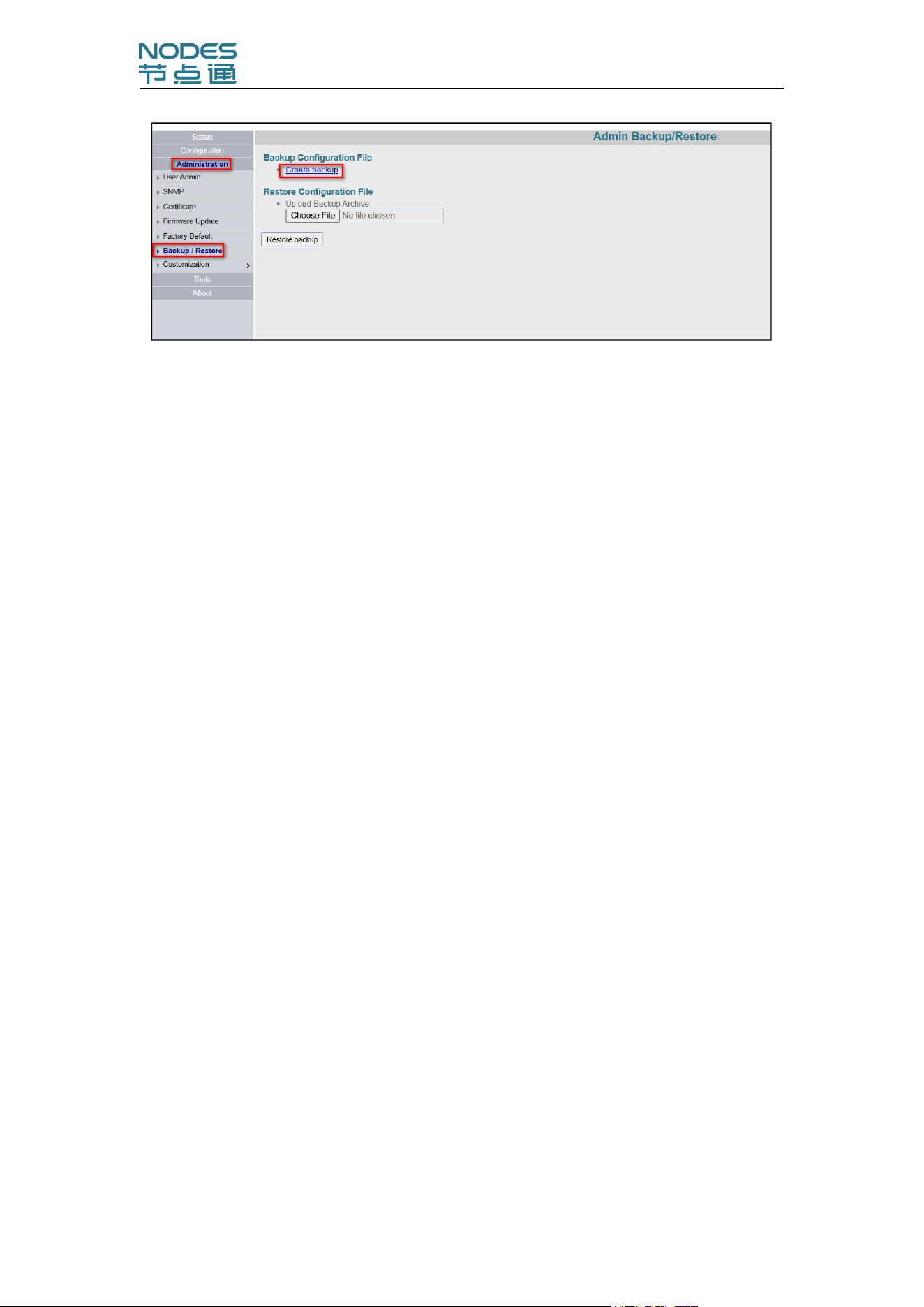
Configuration Import and Export
Backup configuration:
click in sequence,"Administration→Backup/Restore→Create Backup"
Restore configuration:click in
sequence,"Administration→Backup/Restore→Upload Backup
Archive→Restore Configuration"
Configuration Manual-IWR-2458-AC-S-I
22
Attention:Please change the IP address for the device.
Configuration Manual-IWR-2458-AC-S-I
23
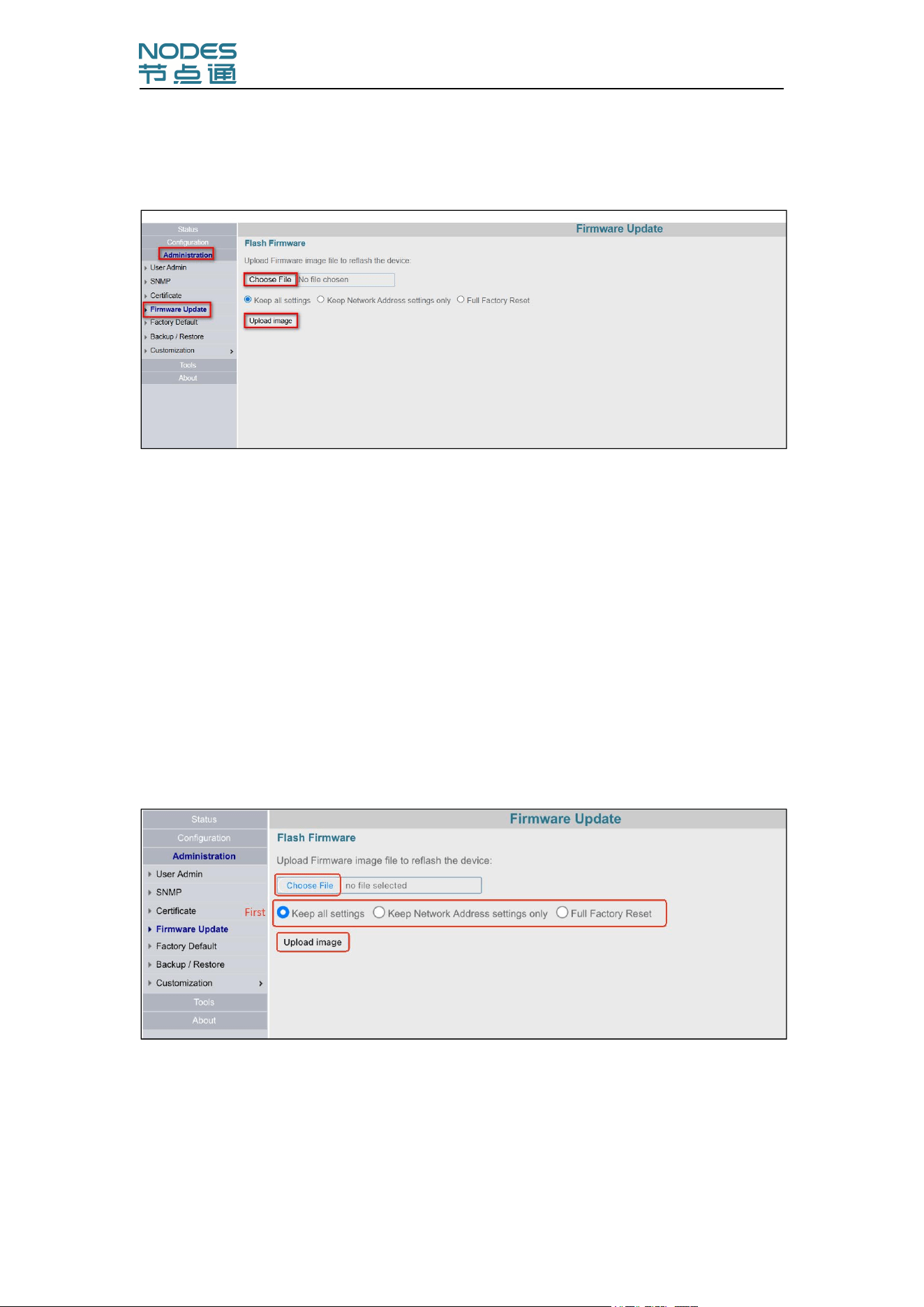
Firmware Update
Click “Administration→ Firmware Upgrade”:
Before clicking “Choose File” to upload the firmware, choose one of the
three configuration retention strategies based on your actual needs:
Keep All Settings: The upgrade will keep all configurations;
Keep Network Address settings Only: The upgrade will only keep the
network-related configurations.
Full Factory Reset: The upgrade will restore the device to its factory
configuration simultaneously.
Example: Select“Keep All Settings”, choose the corresponding firmware
file and click “Upload image”, as shown below:
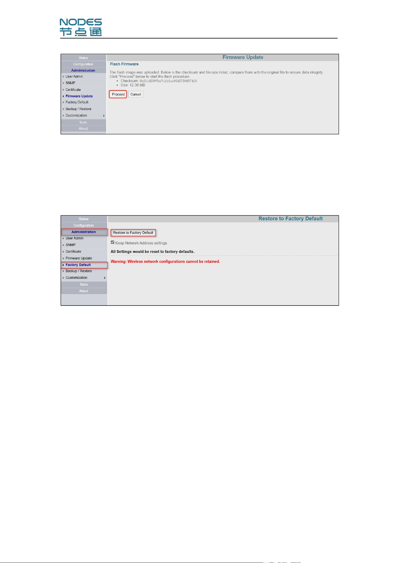
After the firmware file is successfully uploaded, click “Proceed” and wait for
the AP upgrade to complete, as shown below:
Configuration Manual-IWR-2458-AC-S-I
24
Attention:Please do not power off the device under any circumstances
during this process.Otherwise it will be sent to the factory for repair!
Load Factory Default
Click "Administration→Factory Default":
1) Restore to Factory Default.
2) Keep Network Address settings:
Check, the device will restored the factory settings but retain the
network configurations;
Uncheck, the device will be fully restored to factory settings, the
device's IP address is restored to the default 192.168.1.222.
FCC Warning
This device complies with Part 15 of the FCC Rules. Operation is subject to the
following two conditions:
(1) This device may not cause harmful interference, and (2) this device must
accept any interference received, including interference that may cause undesired

Configuration Manual-IWR-2458-AC-S-I
25
operation.
NOTE 1: This equipment has been tested and found to comply with the limits for
a Class B digital device, pursuant to part 15 of the FCC Rules. These limits are designed
to provide reasonable protection against harmful interference in a residential
installation. This equipment generates, uses and can radiate radio frequency energy
and, if not installed and used in accordance with the instructions, may cause harmful
interference to radio communications. However, there is no guarantee that
interference will not occur in a particular installation. If this equipment does cause
harmful interference to radio or television reception, which can be determined by
turning the equipment off and on, the user is encouraged to try to correct the
interference by one or more of the following measures:
- Reorient or relocate the receiving antenna.
- Increase the separation between the equipment and receiver.
-Connect the equipment into an outlet on a circuit different from that to which
the receiver is connected.
-Consult the dealer or an experienced radio/TV technician for help.
NOTE 2: Any changes or modifications to this unit not expressly approved by the
party responsible for compliance could void the user's authority to operate the
equipment.
RF Exposure Statement
To maintain compliance with FCC'S RF Exposure guidelines, This equipment
should be installed and operated with minimum 20cm between the radiator and your
body. This device and its antenna(s) must not be co-located or operation in conjunction
with any other antenna or transmitter.

EU Declaration of Conformity (DoC)
Company name
Beijing Nodes Network Technology Co., Ltd.
Address
Rm705, Shenzhou Building, No.31 Zhongguancun, South
Street, Haidian District, Beijing, 100081, China
Name of Contact
Su Xie
Title
Manager
Phone number
13601232288
E-mail address
We declare that the DoC is issued under our sole responsibility and belongs
to the following product:
Equipment manufacturer
Beijing Nodes Network Technology Co., Ltd.
Model Type
IWR-2458-AC-5P
Product description
AP/CPE
HW version
1.5
SW version
2.2.1.1956T17
Optional accessories or
System components
/
The object of the declaration described above is in conformity with the
relevant Union Harmonization Legislation:
RE Directive 2014/53/EU
The Notified Body Name: Compliance Testing, LLC, has conducted the
conformity assessment according to module B of Directive 2014/53 / EU (RED)
and issues the EU type certificate [XXXXXXX].
The following standards and technical specifications have been applied for

RE Directive 2014/53/EU:
Article 3.1a: Safety and
Health
EN IEC 62368-1:2024+A11:2024
EN 50665:2017
Article 3.1b: EMC
EN 301489-1 V2.2.3 (2019-11)
EN 301489-17 V3.3.1 (2024-09)
EN 55032 :2015+A11 :2020+A1 :2020
EN 55035 :2017+A11 :2020
EN IEC 61000-3-2:2019+A2:2024
EN 61000-3-3:2013+A2:2021+ AC:2022-01
Article 3.2: RF Spectrum
Efficiency
EN 300328 V2.2.2 (2019-07)
EN 301893 V2.2.1 (2024-11)
Article 3.3: Special
requirements invoked
Not applicable
The following standards and technical specifications have been applied for
the other European Legislation:
N/A
Signed on behalf of: Beijing Nodes Network Technology Co., Ltd.
2/3/2026
Print name: Su Xie
Title: Manager
Signature: