7200APP
6000 COUNTS
DC/AC TRUE-RMS CLAMP MULTIMETER
OPERATION MANUAL
1. Overview
The auto range clamp multimeter is a portable and stable
performance. Using 6000 counts digit LCD monitor with character
16mm high. With overall circuitry design centering on large-scale IC
A/D converters in conjunction and over-load protection circuit, the
meters give excellent performance and exquisite making as a
handy utility instrument.
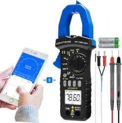
The meter can be connected with mobile phone by Bluetooth, and
display on phone by APP, you can remote monitoring the
measurement condition, the distance control is 10~15m.
The meters can be used to measure DC & AC voltage, DC & AC
current,
resistance, capacitor, frequency, duty cycle, temperature, Non
Contact AC
Voltage (NCV) detection, positive diode voltage fall and audible
continuity.
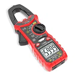
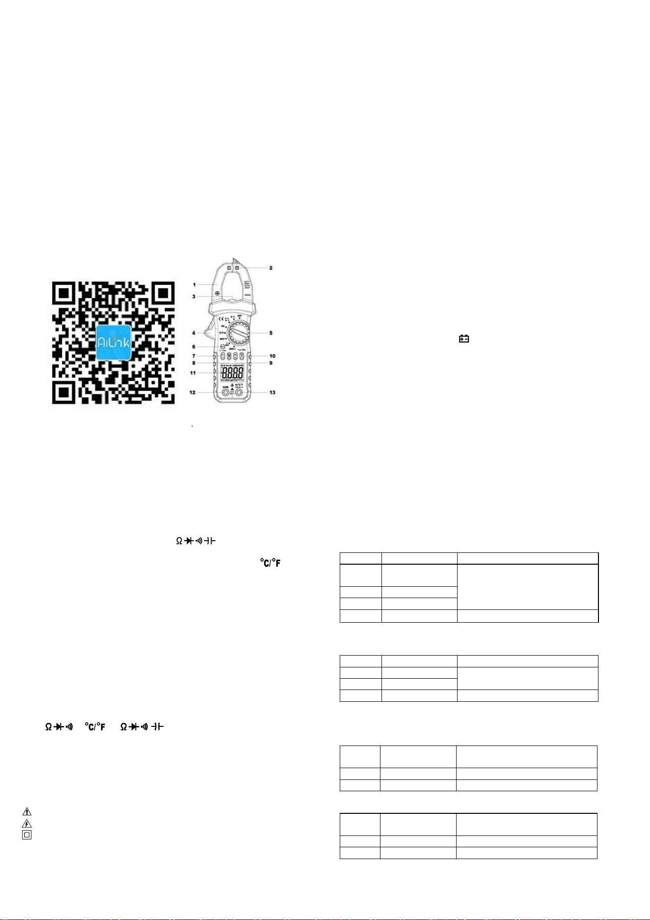
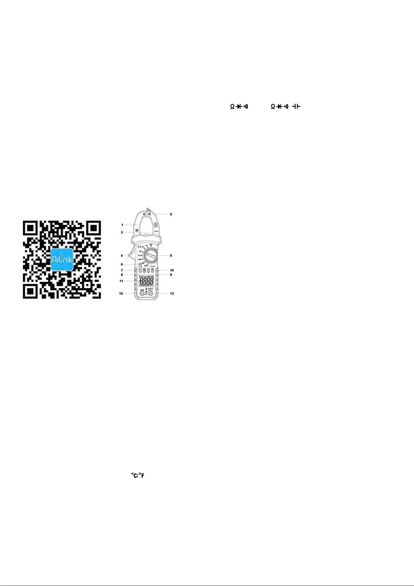
2. Panel Layout
1. Clamp jaws: Opens 26mm to enclose conductor.
2. NCV detection area (bottom).
3. Lamp light: Press the “HOLD” key over 2 seconds to light the
lamp light, it will light up too when the built-in buzzer sounds.
4. Jaw-opening handle: Opens and closes the jaws.
5. Rotary Switch: Use this switch to select functions and ranges.
6. HOLD key: Press the “HOLD” key to lock display value, and the
“DH” sign will appear on the display, press it again to exit. Press
“HOLD” key more than 2 seconds, the back light and the lamp light
will light up, press it more than 2 seconds again, the back light and
the lamp light will light off.
7. SEL key: This key work on the " " range, press the key
to choose resistance, continuity, diode or capacitance test, on the
voltage or current range, change to DC or AC, on the range,
change to ℃ or ℉ test; If press and hold SEL key to power on,
“Auto Power Off ” function will be disabled.
8. MAX/MIN key: Press the “MAX/MIN” key to lock MAX or MIN
value, and the “MAX” or “MIN” sign will appear on the display, press
it over 2 seconds to exit.
9. REL Key: Press the “REL” key, the meter enters relative
measuring mode, “△” is displayed on the LCD and the present
reading becomes the reference value and displayed on the display.
Relative measurement REL△=measurement value-Reference
value. Press it again to exit.
10. Hz/Duty Key: On “ACV/ACA” or “Hz” range, press the “Hz%”
key, you can choose the Frequency or Duty Cycle measurement.
11. LCD display: 6000 counts digit, full function symbol display.
12. COM: COM and Temperature “-” Input Jack
13. V Hz : V/ / /Hz/T+ Input Jack
3. Safety Information
3-1 The meter is designed according to IEC-1010 concerning
electronic measuring instruments with an over-voltage category
600V (CAT Ⅱ) and pollution 2.
3-2 Follow all safety and operating instructions to ensure that the
meter is used safely and is kept in good operating condition.
3-3 safety symbols:
Important safety information, refer to the operating manual.
Dangerous voltage may be presence.
Double insulation (protection Class II)
4. Special Cautions for Operation
4-1 The meters can be safe only according to standard procedures
when used in conjunctions with the supplied test leads. To replace
damaged test leads with only the same model or same electric
specifications.
4-2 To avid risk of electric shock, do not use the meters before the
cover is in place.
4-3 The range switch should be right position for the testing.
4-4 To avoid electric shock and damaging the instruments, the input
signals are forbidden to exceed the specified limits.
4-5 When measuring TV set or switched power, attention should be
paid to the possible pulses that may bring destruction to the circuit.
4-6 Range switch position is forbidden to be changed at random
during measurement.
4-7 Take caution against shock in the course of measuring voltage
higher than DC 60V & AC 30V.
4-8 Before opening the cover of the battery cabinet to replace
batteries. disconnect the test leads from any external circuit, set
the selector switch to "OFF" position.
4-9 Keep the fingers after the protection ring when measuring
through the instrument lead.
4-10 Keep the fingers after the protection ring when measuring
through the clamp.
4-11 After operation is finished, set function switch at OFF to save
battery power.
4-12 If the meter is without usage for long time, take out battery to
avoid damage by battery leakage.
5. GENERAL SPECIFICATIONS
5-1 Max Voltage between input terminal and Earth Ground:
CAT Ⅱ 600V or CAT Ⅲ 300V
5-2 Over-range Indication: display “OL” for the significant digit.
5-3 Automatic display of negative polarity “-” .
5-4 Low Battery Indication: “ ” displayed.
5-5 Max LCD display: 6000 counts digit.
5-6 Auto range control
5-7 Auto Power Off: When measurement exceeds 15 minutes
without switching mode and pressing key, the meter will switch
to standby mode. Press any key to exit standby mode. When
restart the system, press and hold SEL key to disable auto
power off.
5-8 Clamp opening size: 26mm.
5-9 Power supply: 1.5V×2 “AAA” R03P battery
5-10 Operating Temp.: 0℃ to 40℃ (relative humidity <85%)
5-11 Storage Temp.:-10℃ to 50℃ (relative humidity <85%)
5-12 Guaranteed precision Temp.: 23±5℃ (relative humidity <70%)
5-13 Dimension: 207(H)×75(W)×37(D)mm.
5-14 Weight: Approx. 280g (including battery).
6. Testing Specifications
Accuracy is specified for a period of year after calibration and at
18℃ to 28℃
(64℉ to 82℉) with relative humidity to 70%.
6-1 DC Voltage
Range
Resolution
Accuracy
600m
V
0.1mV
±(0.5% of rdg + 2 digits)
6V
1mV
60V
10mV
600V
100mV
±(0.8% of rdg + 2 digits)
-- Impedance: 10MΩ, More than 100MΩ on 600mV range
-- Overload protection: 600V DC or AC rms
6-2 AC Voltage (True RMS)
Range
Resolution
Accuracy
6V
1mV
±(1.0% of rdg + 3 digits)
60V
10mV
600V
100mV
±(1.5% of rdg + 3 digits)
-- Impedance: 10MΩ
-- Overload protection: 600V DC or AC rms
-- Frequency Range: 40 to 2kHz
6-3 DC Current
Rang
e
Resolution
Accuracy
60A
10mA
±(2.5% of rdg + 10 digits)
400A
100mA
±(3.0% of rdg + 10 digits)
-- Overload protection: 400A DC or AC rms
6-4 AC Current (True RMS)
Rang
e
Resolution
Accuracy
60A
10mA
±(2.5% of rdg + 10 digits)
400A
100mA
±(3.0% of rdg + 10 digits)
-- Overload protection: 400A DC or AC rms
-- Frequency Range: 40 to 100Hz
6-5 Resistance
Rang
e
Resolution
Accuracy
600Ω
0.1Ω
±(1.0% of rdg + 3 digits)
6kΩ
1Ω
±(1.0% of rdg + 2 digits)
60kΩ
10Ω
600kΩ
100Ω
6MΩ
1kΩ
60MΩ
10kΩ
±(1.5% of rdg + 3 digits)
-- Overload protection: 250V DC or AC rms
6-6 Capacitance
Range
Accuracy
Resolution
6nF
±(5.0% of rdg + 10
digits)
1pF
60nF
±(3.0% of rdg + 10
digits)
10pF
600nF
100pF
6µF
1nF
60µF
±(5.0% of rdg + 10
digits)
10nF
600µF
±(10.0% of rdg + 20
digits)
100nF
6mF
1µF
60mF
10µF
-- Overload protection: 250V DC or AC rms
6-7 Frequency
Range
Accuracy
Resolution
9.999Hz
± (0.1% of rdg + 5 digits)
0.001Hz
99.99Hz
0.01Hz
999.9Hz
0.1Hz
9.999kHz
1Hz
99.99kHz
10Hz
999.9kHz
100Hz
9.999MH
z
1kHz
-- Sensitivity: sine wave 0.6V rms (9.999MHz: 1.5V rms)
-- Overload protection: 250V DC or AC rms
6-8 Duty cycle
0.1%~99.9%: ± ( 2.0% of rdg + 2 digits ), Frequency lower than
10kHz
-- Sensitivity: sine wave 0.6V rms
-- Overload protection: 250V DC or AC rms
6-9 Temperature
Rang
e
Accuracy
Resolution
℃
-20~150℃
± ( 3℃+ 1digit )
1℃
150~1000
℃
± ( 3% of rdg +
2digits )
℉
-4~302℉
± ( 5℉+ 2digits )
1℉
302~1832
℉
± ( 3% of rdg +
3digits )
-- NiCr-NiSi K-type sensor
-- Overload protection: 250V DC or AC rms
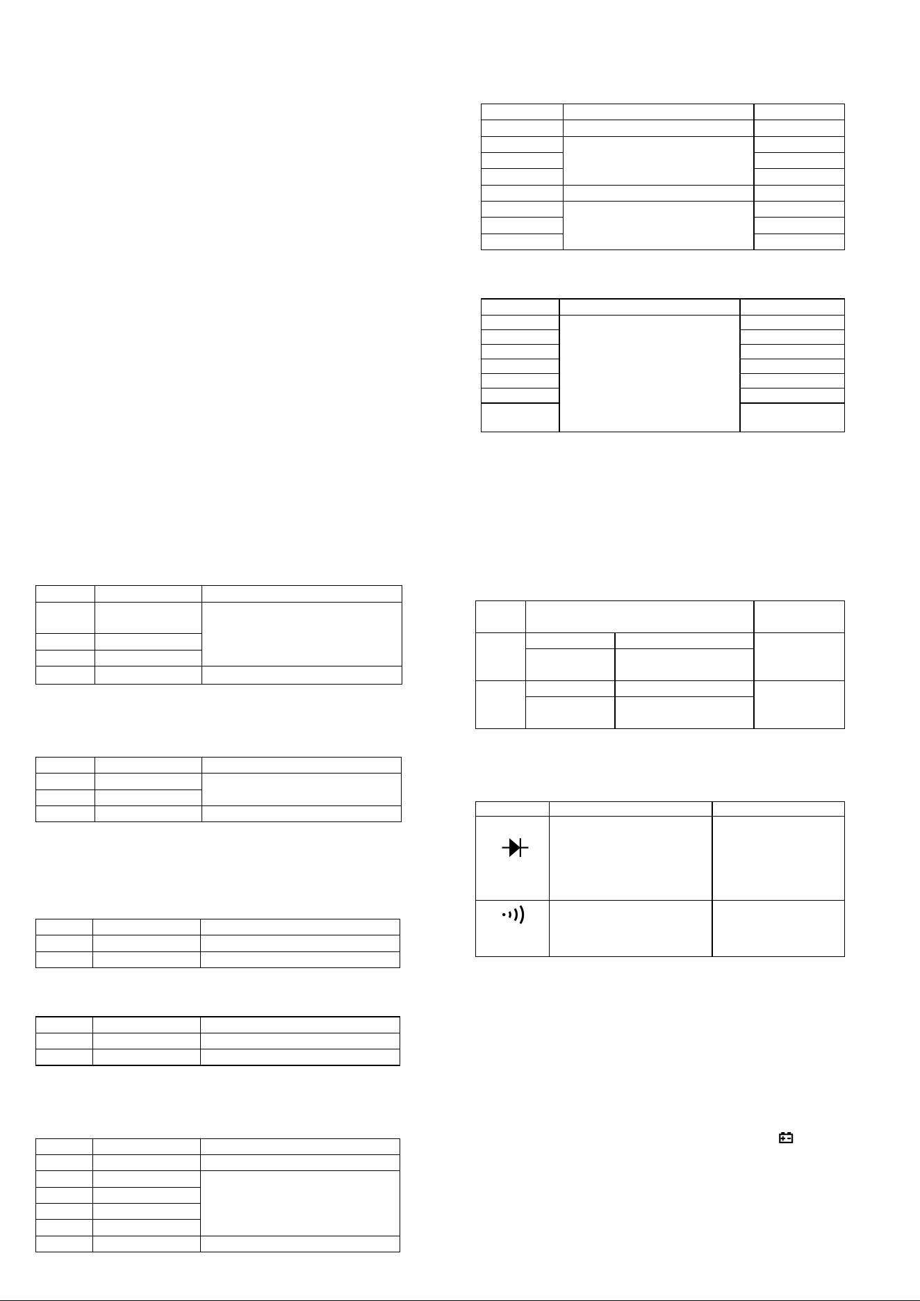
6-10 Diode and Audible continuity test
Range
Description
Test Condition
Display read
approximately
forward voltage of
diode
Forward DC
current
approx. 1.5mA
Reversed DC
voltage
approx. 4V
Built-in buzzer sounds
and the lamp light will
light up if resistance is
less than 50Ω
Open circuit
voltage
approx. 2V
Overload protection: 250V DC or AC rms
6-11 Non Contact AC Voltage (NCV) detection
Test voltage range: 90V~1000V AC rms
The lamp light will light up together with sound.
7. OPERATING INSTRUCTIONS
7-1 Attention before operation
7-1-1 Check battery. When the battery voltage drop below proper
operation range, the “ ” symbol will appear on the LCD display
and the battery need to changed.
7-1-2 Pay attention to the “ ” besides the input jack which shows
that the input voltage or current should be within the specified
value.
7-1-3 The range switch should be positioned to desired range for
measurement before operation.
7-2 Measuring DC & AC Voltage
7-2-1 Connect the black test lead to COM jack and the red to
V jack.
7-2-2 Set the rotary switch at the desired “V ” range position, it
shows symbol for testing DC voltage, if you want to test AC voltage,
push “SEL” button switch.
7-2-3 Connect test leads across the source or load under
measurement.
7-2-4 You can get reading from LCD. The polarity of the red lead
connection will be indicated along with the DC voltage value.
NOTE:
1.“ ” means you can’t input the voltage more than 600V, it’s
possible to show higher voltage, but it may destroy the inner circuit
or pose a shock.
2. Be cautious against shock when measuring high Voltage.
7-3 Measuring DC & AC Current
7-3-1 Set the rotary switch at the desired “60A ” or “400A ”
range position, it shows symbol for testing DC current, if you want
to test AC current, push “SEL” button switch.
7-3-2 Zero the reading by pressing “REL” key for a reading of zero
on the display.
7-3-3 Disconnect the test leads from the Meter.
7-3-4 Clamp the Jaws around the one conductor to be measured.
Center the conductor within the Jaw using the Centering Marks
as guides.
7-3-5 You can get reading from LCD. The arrow in the Jaw
indicates the direction of positive current flow (positive to
negative).
NOTE:
1. When the value scale to be measured is unknown beforehand,
set the range selector at the highest position.
2. When only “OL” is displayed, it indicates over-range situation and
the higher range has to be selected.
7-4 Measuring Resistance
7-4-1 Connect the black test lead to COM jack and the red to
V jack.
7-4-2 Set the rotary switch at the desired “ ” range position.
7-4-3 Connect test leads across the resistance under
measurement.
7-4-4 You can get reading from LCD.
NOTE: Max. input overload: 250V rms<10sec
1. For measuring resistance above 1MΩ, the mete may take a few
seconds to get stable reading.
2. When the input is not connected, i.e. at open circuit, the figure
‘OL’ will be displayed for the over-range condition.
3. When checking in-circuit resistance, be sure the circuit under test
has all power removed and that all capacitors have been
discharged fully.
7-5 Measuring Capacitance
7-5-1 Connect the black test lead to COM jack and the red to
V jack.
7-5-2 Set the rotary switch at the desired “ ” range position,
push “SEL” to choose Capacitance measurement.
7-5-3 Connect test leads across the capacitance under
measurement.
7-5-4 You can get reading from LCD.
NOTE: Max. input overload: 250V rms<10sec
1.
Capacitors should be discharged before being tested.
2.
When testing large capacitance, it will take longer time before
the final indication (For 100uF~99.99mF range, it will take about
10 seconds).
3.
When testing small capacitance (≤1uF), to assure the
measurement accuracy, first press "REL", then go on
measuring.
7-6 Measuring Frequency & Duty cycle
7-6-1 Connect the black test lead to COM jack and the red to
V jack.
7-6-2 Set the rotary switch at the desired “Hz” range position.
7-6-3 Push “Hz%” key to choose Frequency or Duty cycle test.
7-6-3 Connect the probe across the source or load under
measurement.
7-6-4 You can get reading from LCD.
7-7 Measuring Temperature
7-7-1 Connect the black banana plug of the sensor to COM jack
and the red banana plug to the V jack.
7-7-2 Set the rotary switch at the desired “ ” range position,
push “SEL” to choose ℃ or ℉ measurement.
7-7-3 Put the sensor probe into the temperature field under
measurement.
7-7-4 You can get reading from LCD.
NOTE:
1. The accessory of the meter WRNM-010 type contact
thermocouple limit temperature is 250 ℃ (300 ℃ shortly), please
use special probe for test higher temperature.
2. Please don't change the thermocouple at will, otherwise we can't
guarantee to measure accuracy.
3. Please don’t importing the voltage in the temperature function.
7-8 Diode & Audible continuity Testing

7-8-1 Connect the black test lead to COM jack and the red to
V jack.
7-8-2 Set the rotary switch at the “ ” range position, push
“SEL” to choose Diode or Audible continuity measurement.
7-8-3 On diode range, connect the test leads across the diode
under measurement, display shows the approx. forward
voltage of this diode.
7-8-4 On Audible continuity range, connect the test leads to two
point of circuit, if the resistance is lower than approx. 50Ω, the
lamp light will light up together with sound.
NOTE: Make sure the power is cut off and all capacitors need to be
discharged under this measurement.
7-9 Non Contact AC Voltage detection
7-9-1 Set the rotary switch at the desired “NCV” range position.
7-9-2 Hold the meter so that the bottom of the mater’s clamp jaws
right is vertically and horizontally centered and contacting the
conductor, when the live voltage ≥ 90V AC rms, the lamp light
will light up together with sound.
NOTE:
1. Even without LED indication, the voltage may still exist. Do not
rely on non-contact voltage detector to determine the presence of
voltage wire. Detection operation may be subject to socket design,
insulation thickness and different type and other factors.
2. When the meter input terminals presence voltage, due to the
influence of presence voltage, voltage sensing indicator may also
be bright.
3. Keep the meter away from electrical noise sources during the
tests, i.e., florescent lights, dimmable lights, motors, etc.. These
sources can trigger Non-Contact AC Voltage detection function and
invalidate the test.
8. Battery replacement
8-1 When the battery voltage drop below proper operation range
the " " symbol will appear on the LCD display and the battery
need to changed.
8-2 Before changing the battery, set the selector switch to “OFF”
position and remove the test leads from the terminals. Open the
cover of the battery cabinet by a screwdriver.
8-3 Replace the old battery with the same type battery (AAA R03P
1.5V×2).
8-4 Close the cover of the battery cabinet and fasten the screw.
9. Maintenance
9-1 You must replace the test leads if the lead is exposed, and
should adopt the leads with the same specifications as origin.
9-2 Do not use the meter before the back cover is properly closed
and screw secured. Upon any abnormality, stop operation
immediately and send the meter for maintenance.
9-3 When take current measurement, keep the cable at the center
of the clamp will get more accurate test result.
9-4 Repairs or servicing not covered in this manual should only by
qualified personal.
9-5 Periodically wipe the case with a dry cloth and detergent. Do
not use abrasives or solvents on this instruments.
9-6 Please take out the battery when not using for a long time.
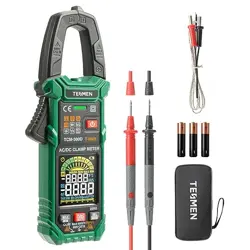
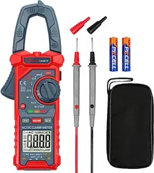
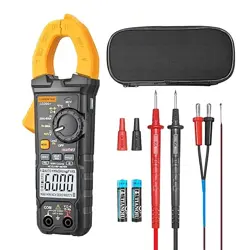
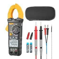
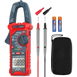
10. Accessories
[1] Test Leads: electric rating 600V 10A
[2] “K” type thermocouple sensor probe
[3] Operator’s Manual
Above picture and content just for your reference. Please be
subject to the actual products if anything different or updated.
Please pardon for not informing in advance.
AILink User Manual
Summary
AiLink is a comprehensive intelligent hardware
management platform. Through AiLink App, you can
complete the convenient between mobile phones and
intelligent hardware,achieve the interconnection and
intercommunication between devices and users. AILink
supports multiple types of devices, such as smart health,
smart security, smart electricians.
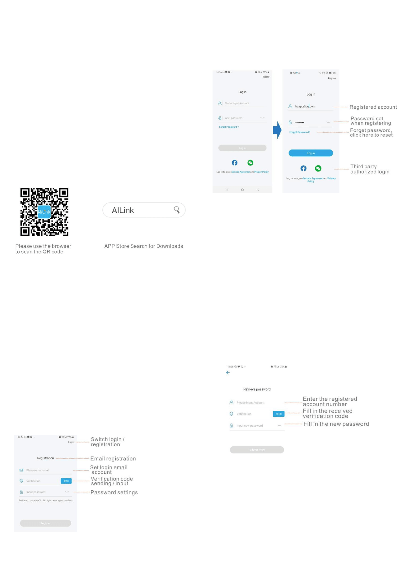
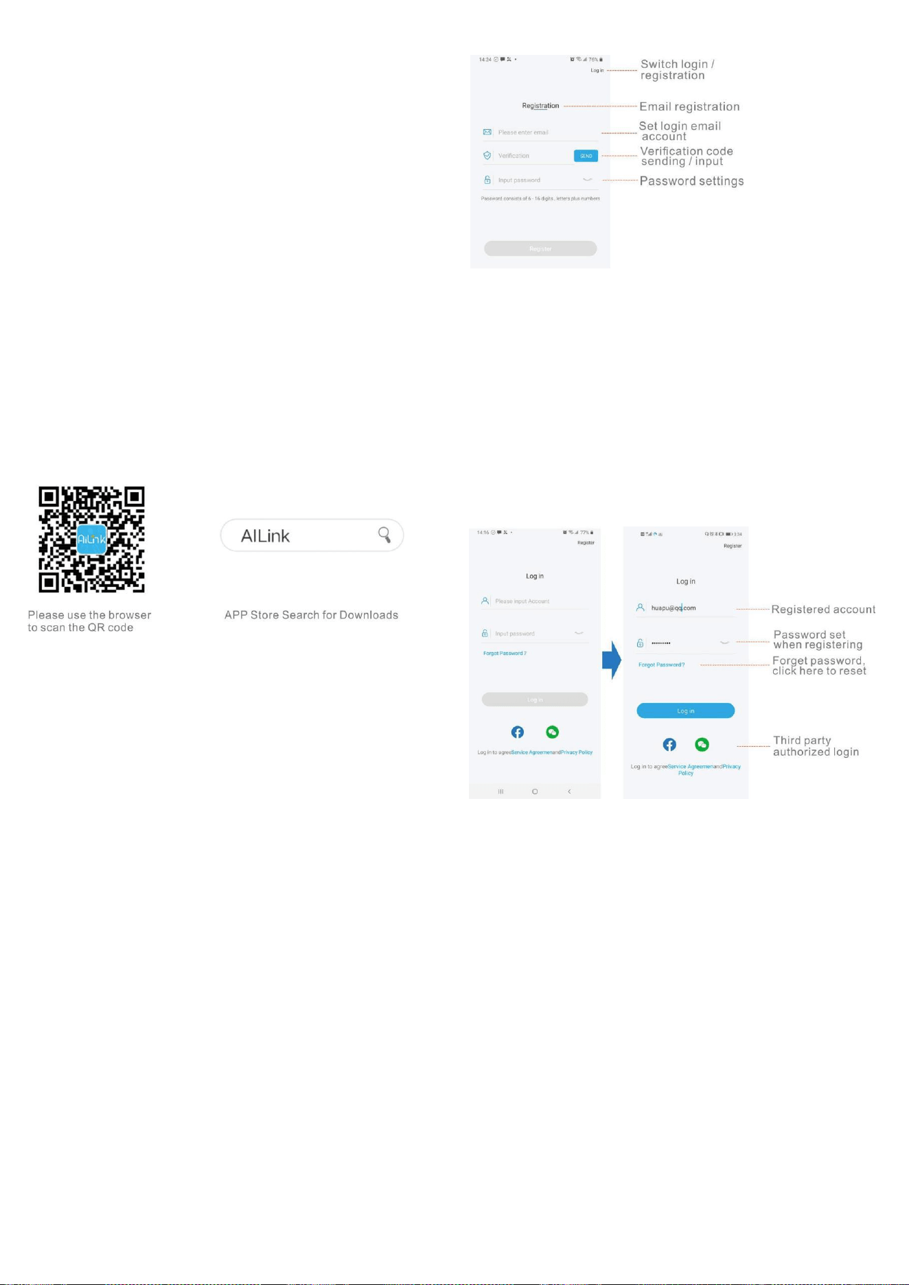
APP download and installation
Scan the below QR code to download directly, or search
for "AILink" in the APP Store, download and install the
"AILink".
Account registration
1.Set up an account: select the method of registration:
mobile phone or email, enter the content, this account is
used for login;
2.Verify the account: Click the "Send" button to send a
verification code to the registered account to verify the
accuracy of the account. The verification code is sent in
120s. If you have not received it over time, please click
Send again;
3.Set the password: In order to ensure the security of the
account, the password must be composed of 6-16 digits +
grapheme;
4.All settings are completed, click on register to complete
the registration;
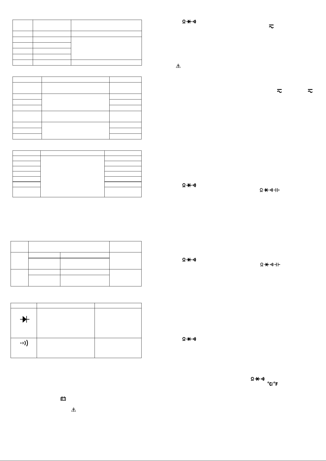
Login
1.Account + password login: Set up an account and
password through registration, and log in with the set
account + password;
2.Third-party application authorized login: currently
supports WeChat and facebook authorized login.
Forgot Password
When the user forgets the password, he can reset the
password through this setting
1.Enter the account that needs to retrieve the password;
2.Send verification code: Click the "Send" button to send
the verification code to the entered account, verify the
account, the sending time of the verification code is 120s,
if you didn’t received that in time, please click send again;
3.Reset password: the setting method is the same as that
account registration;
4.All settings are completed, click "Submit Reset" to
complete, you can use the new password to log in to the
APP;
Supplement master account information
Due to the diversity of supported devices, it is necessary
to set an head portrait, nickname, birthday, and gender
when creating a user. The supplementary information is
used for data calculation of some devices and analysis of
measurement data
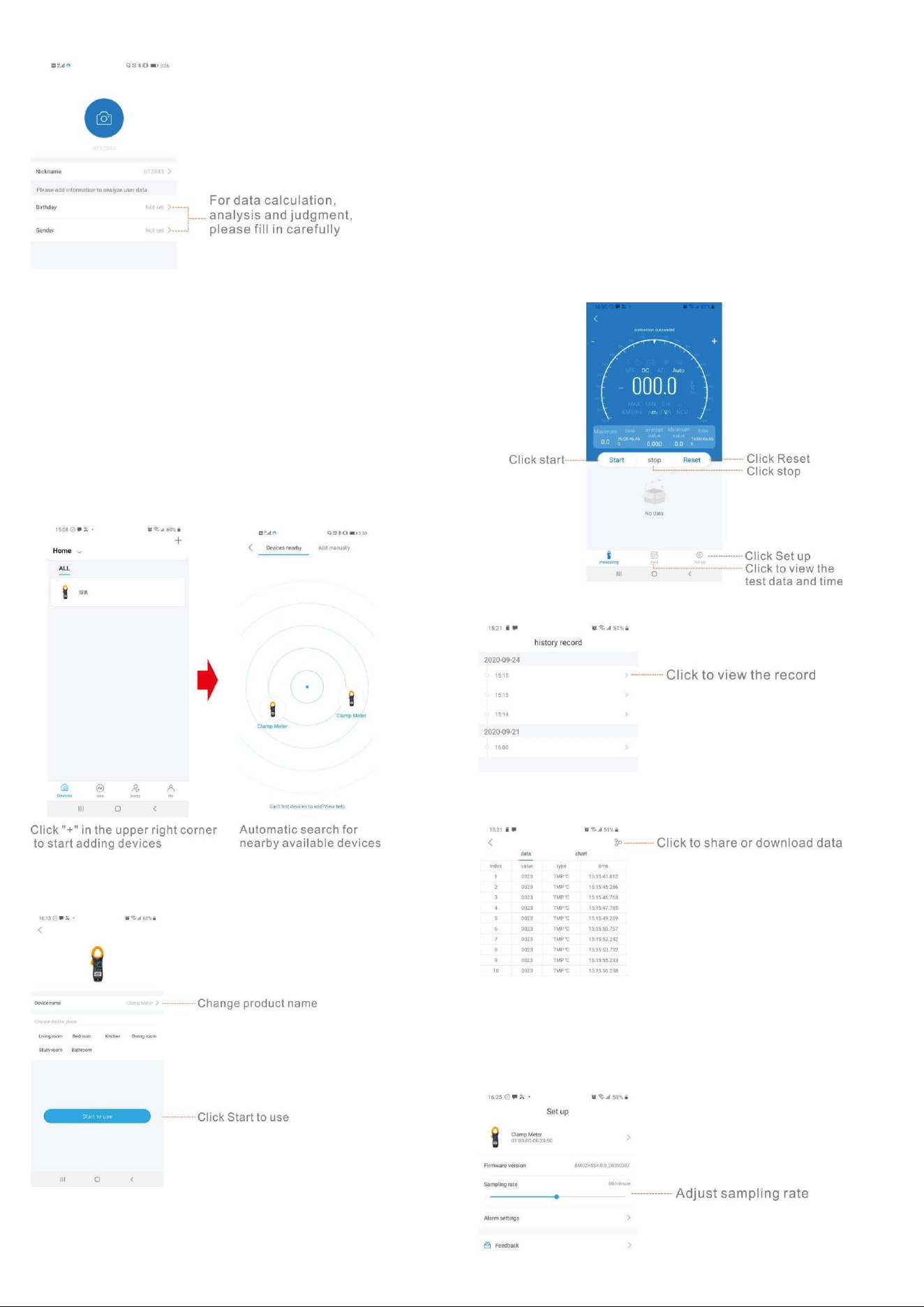
Bonding/connecting devices
There are two ways to bond devices: nearby devices,
manually add
1.Nearby devices: Open the device page to automatically
search for nearby matching devices, and click the
searched
device to automatically bond;
2.Manually add: select the device that needs to be added
and operate according to the operating instructions to
add;
1) Click the image of the device to be used, set the name,
and click "start to use" to start using.
2)The Maximum or Minimum value and corresponding
time will display on the mobile phone APP, and the
average value in a period of time from start measurement
will display too.
3)Press the "start" key to start recording the
measurement data, and press the "stop" key to stop this
recording. Press the "reset" key to reset and stop the
measurement, the old data will be cleared and the
recording will start again.
4)Click the "data" button to view the historical record time
and historical record data, and press the button in the
upper right corner to share or download the data.
5)Click the "set up" button to set the name of the
instrument, view the firmware version or set the sampling
rate.

Feedback
With any comments or suggestions, you can tell us through this
function to help us improve the product and make the product
better. After receiving the feedback, we will deal with it as
soon as possible. The problem is described in detail as much as
possible, and the corresponding picture can be added to the
APP problem. , In order to supplement the description more
clearly, the programmer can reproduce the problem and solve
the problem faster.
CONTACT US
For any problem or concern, welcome to email us for
prompt response.
P.S.
To make sure you can receive immediate solution and
your requests processed quickly, please email us with
these information:
1.Order Number
2.Platform of Your Purchase
3.Full Model Number
4.Description of the Problem(Attaching videos or photos can
help us troubleshoot the problems evenfaster)
7200APP
6000 カウント
DC / AC TRUE-RMS クランプマルチメータ
取扱説明書
1.概要
オートレンジクランプマルチメータは、ポータブルで安定した
性能です。 高さ 16mm の 6000 カウント桁液晶モニターを使
用。 大規模な ICA / D コンバーターを中心とした全体的な回
路設計と過負荷保護回路を備えたメーターは、便利なユーテ
ィリティ機器として優れたパフォーマンスと絶妙な製造を提供
します。メーターは Bluetooth で携帯電話に接続でき、APP で
電話に表示でき、測定条件を遠隔監視でき、距離制御は 10
〜15m です。メーターは、DC および AC 電圧、DC および AC
電流、抵抗、コンデンサ、周波数、デューティサイクル、温度、
非接触 AC 電圧(NCV)の検出、正のダイオード電圧の低下、
および可聴導通。
2.パネルレイアウト
1.クランプジョー:導体を囲むために 26mm 開きます。
2. NCV 検出領域(下)。
3.ランプライト:「HOLD」キーを 2 秒以上押してランプライトを
点灯させます。内蔵ブザーが鳴るとランプライトも点灯しま
す。
4.ジョーオープニングハンドル:ジョーを開閉します。
5.ロータリースイッチ:このスイッチを使用して、機能と範囲を
選択します。
6. HOLD キー:「HOLD」キーを押して表示値をロックすると、
ディスプレイに「DH」記号が表示されます。もう一度押すと終
了します。 「HOLD」キーを 2 秒以上押すと、バックライトとラ
ンプライトが点灯し、もう一度 2 秒以上押すと、バックライトと
ランプライトが消灯します。
7. SEL キー:このキーは「」範囲で機能し、キーを押して抵抗、
導通、ダイオードまたは静電容量テストを選択し、電圧または
電流範囲で、DC または AC に変更し、 範囲で、℃または
℉テストに変更します。SEL キーを長押しして電源を入れる
と、「自動電源オフ」機能が無効になります。
8. MAX / MIN キー:「MAX / MIN」キーを押して MAX または
MIN 値をロックすると、ディスプレイに「MAX」または「MIN」記
号が表示されます。2 秒以上押して終了します。
9. REL キー:「REL」キーを押すと、メーターが相対測定モード
になり、LCD に「△」が表示され、現在の読み取り値が基準値
になり、ディスプレイに表示されます。相対測定 REL△=測定
値-参考値。もう一度押すと終了します。
10. Hz /デューティキー:「ACV / ACA」または「Hz」範囲で、
「Hz%」キーを押します。周波数またはデューティサイクルの
測定を選択できます。
11. LCD ディスプレイ:6000 カウント桁、全機能シンボルディス
プレイ。
12. COM:COM および温度「-」入力ジャック
13. V Hz:V / / / Hz / T +入力ジャック
3.安全情報
3-1 メーターは、過電圧カテゴリー 600V(CATⅡ)および汚染
2 の電子測定器に関する IEC-1010 に従って設計されていま
す。
3-2 すべての安全および操作手順に従って、メーターが安全
に使用され、良好な操作状態に保たれていることを確認して
ください。
3-3 安全記号:
重要な安全情報については、操作マニュアルを参照してくだ
さい。
危険な電圧が存在する可能性があります。
二重絶縁(保護クラス II)
4.操作に関する特別な注意
4-1 メーターは、付属のテストリードと組み合わせて使用した
場合、標準的な手順に従ってのみ安全になります。損傷した
テストリードを同じモデルまたは同じ電気仕様のみと交換す
ること。
4-2 感電の危険を避けるため、カバーを取り付ける前にメータ
ーを使用しないでください。
4-3 レンジスイッチは、テストに適した位置にある必要があり
ます。
4-4 感電や機器の損傷を防ぐため、入力信号が指定された
制限を超えることは禁止されています。
4-5 テレビやスイッチの電力を測定するときは、回路を破壊す
る可能性のあるパルスに注意を払う必要があります。
4-6 レンジスイッチの位置を測定中にランダムに変更すること
は禁止されています。
4-7 DC60V および AC30V より高い電圧を測定する際の衝撃
に注意してください。
4-8 バッテリーキャビネットのカバーを開けてバッテリーを交
換する前。テストリードを外部回路から外し、セレクタースイッ
チを「OFF」の位置に設定します。
4-9 機器のリード線を通して測定するときは、保護リングの後
ろに指を置いてください。
4-10 クランプを通して測定するときは、保護リングの後に指
を置いてください。
4-11 運転終了後、機能スイッチを OFF にして電池を節約して
ください。
4-12 長期間使用しない場合は、電池漏れによる損傷を防ぐ
ため、電池を取り出してください。
5.一般仕様
5-1 入力端子とアース間の最大電圧:
CATⅡ600V または CATⅢ300V
5-2 オーバーレンジ表示:有効桁に「OL」を表示します。
5-3 負極性「-」の自動表示。
5-4 ローバッテリー表示:「」が表示されます。
5-5 最大 LCD ディスプレイ:6000 カウント桁。
5-6 自動範囲制御
5-7 自動電源オフ:モードを切り替えてキーを押さずに測定が
15 分を超えると、メーターはスタンバイモードに切り替わりま
す。いずれかのキーを押して、スタンバイモードを終了しま
す。システムを再起動するときは、SEL キーを押したままにし
て自動電源オフを無効にします。
5-8 クランプ開口部サイズ:26mm。
5-9 電源:1.5V×2「AAA」R03P バッテリー
5-10 動作温度:0℃〜40℃(相対湿度<85%)
5-11 保管温度:-10℃〜50℃(相対湿度<85%)
5-12 保証精度温度:23±5℃(相対湿度<70%)
5-13 寸法:207(H)×75(W)×37(D)mm。
5-14 重量:約。 280g(バッテリー込み)。
6.仕様のテスト
精度は、校正後 1 年間、18℃〜28℃で規定されています。
(64℉から 82℉)相対湿度 70%。
6-1DC 電圧
レンジ
識別度
精度
600m
V
0.1mV
±(0.5% 示度 + 2 字)
6V
1mV
60V
10mV
600V
100mV
±(0.8% 示度 + 2 字)
-インピーダンス:10MΩ、600mV の範囲で 100MΩ以上
-過負荷保護:600VDC または AC 有効値
6-2 AC 電圧(真の RMS)
レンジ
識別度
精度
6V
1mV
±(1.0% 示度 + 3 字)
60V
10mV
600V
100mV
±(1.5% 示度 + 3 字)
-インピーダンス:10MΩ
-過負荷保護:600VDC または AC 有効値
-周波数範囲:40〜2kHz
6-3DC 電流
レンジ
識別度
精度
60A
10mA
±(2.5% 示度 + 10 字)
400A
100mA
±(3.0% 示度 + 10 字)
-過負荷保護:400ADC または AC 有効値
6-4 AC 電流(真の RMS)
レンジ
識別度
精度
60A
10mA
±(2.5% 示度 + 10 字)
400A
100mA
±(3.0% 示度 + 10 字)
-過負荷保護:400ADC または AC 有効値
-周波数範囲:40〜100Hz
6-5 抵抗
レンジ
識別度
精度
600Ω
0.1Ω
±(1.0% 示度 + 3 字)
6kΩ
1Ω
±(1.0% 示度 + 2 字)
60kΩ
10Ω
600kΩ
100Ω
6MΩ
1kΩ
60MΩ
10kΩ
±(1.5% 示度 + 3 字)
-過負荷保護:250VDC または AC 有効値
6-6 静電容量
レンジ
精度
識別度
6nF
±(5.0% 示度+ 10 字)
1pF
60nF
±(3.0% 示度+ 10 字)
10pF
600nF
100pF
6µF
1nF
60µF
±(5.0% 示度+ 10 字)
10nF
600µF
±(10.0%示度+ 20 字)
100nF
6mF
1µF
60mF
10µF
-過負荷保護:250VDC または AC 有効値
6-7 頻度
レンジ
精度
識別度
9.999Hz
± (0.1% 示度+ 5 字)
0.001Hz
99.99Hz
0.01Hz
999.9Hz
0.1Hz
9.999kHz
1Hz
99.99kHz
10Hz
999.9kHz
100Hz
9.999MH
z
1kHz
-感度:正弦波 0.6V 有効値(9.999MHz:1.5V 有効値)
-過負荷保護:250VDC または AC 有効値
6-8 デューティサイクル
0.1%〜99.9%:±(2.0%示度+ 2 字)、周波数が 10kHz 未満
-感度:正弦波 0.6V 有効値
-過負荷保護:250VDC または AC 有効値
6-9 温度
レン
ジ
精度
識別度
℃
-20~150℃
± ( 3℃+ 1 字)
1℃
150~1000
℃
± ( 3% 示度 + 2
字 )
℉
-4~302℉
± ( 5℉+ 2 字 )
1℉
302~1832
℉
± ( 3% 示度 + 3
字 )
--NiCr-NiSiK 型センサー
-過負荷保護:250VDC または AC 有効値
6-10 ダイオードと可聴導通テスト
レンジ
説明
試験条件
Display read
approximately
forward voltage of
diode
Forward DC
current
approx. 1.5mA
Reversed DC
voltage
approx. 4V
Built-in buzzer sounds
and the lamp light will
light up if resistance is
less than 50Ω
Open circuit
voltage
approx. 2V
過負荷保護:250VDC または AC 有効値
6-11 非接触 AC 電圧(NCV)の検出
試験電圧範囲:90V〜1000V AC 有効値
ランプライトが音とともに点灯します。
7.操作手順
7-1 操作前の注意
7-1-1 バッテリーを確認してください。バッテリー電圧が適切
な動作範囲を下回ると、LCD ディスプレイに「 」記号が表示
され、バッテリーを交換する必要があります。
7-1-2 入力ジャックの横にある「」に注意してください。これ
は、入力電圧または電流が指定された値内にある必要があ
ることを示しています。
7-1-3 レンジスイッチは、操作前に測定したい範囲に配置す

る必要があります。
7-2DC および AC 電圧の測定
7-2-1 黒のテストリードを COM ジャックに接続し、赤を V
ジャックに接続します。
7-2-2 ロータリースイッチを希望の「V 」レンジ位置に設定し
ます。DC 電圧をテストするための記号が表示されます。AC
電圧をテストする場合は、「SEL」ボタンスイッチを押します。
7-2-3 テストリードをソースまたは測定中の負荷に接続しま
す。
7-2-4LCD から読み取りを取得できます。赤いリード線接続
の極性は、DC 電圧値とともに示されます。
注意:
1.「 」は、600V を超える電圧を入力できないことを意味し、よ
り高い電圧を表示することは可能ですが、内部回路を破壊し
たり、衝撃を与える可能性があります。
2.高電圧を測定するときは、感電に注意してください。
7-3DC および AC 電流の測定
7-3-1 ロータリースイッチを希望の「60A 」または「400A 」
の範囲位置に設定します。DC 電流をテストするための記号
が表示されます。AC 電流をテストする場合は、「SEL」ボタン
スイッチを押します。
7-3-2「REL」キーを押して読み取り値をゼロにすると、ディス
プレイの読み取り値がゼロになります。
7-3-3 テストリードをメーターから外します。
7-3-4 測定する 1 つの導体の周りにジョーをクランプします。
センタリングマークをガイドとして使用して、導体をジョー内で
センタリングします。
7-3-5LCD から読み取りを取得できます。 ジョーの矢印は、
正の電流の流れの方向(正から負)を示しています。
注意:
1.事前に測定する値目盛がわからない場合は、レンジセレク
ターを一番高い位置に設定してください。
2.「OL」のみが表示されている場合は、レンジ超過の状況を
示しており、より高いレンジを選択する必要があります。
7-4 抵抗の測定
7-4-1 黒のテストリードを COM ジャックに接続し、赤を V
ジャックに接続します。
7-4-2 ロータリースイッチを希望の「 」範囲位置に設
定します。
7-4-3 測定中の抵抗の両端にテストリードを接続します。
7-4-4LCD から読み取りを取得できます。
注意:
最大 入力過負荷:250V 有効値 <10 秒
1.1MΩを超える抵抗を測定する場合、安定した読み取り値が
得られるまでに数秒かかる場合があります。
2.入力が接続されていない場合、つまり開回路の場合、オー
バーレンジ状態の場合は「OL」の数字が表示されます。
3.回路内抵抗を確認するときは、被試験回路の電源がすべ
て切断され、すべてのコンデンサが完全に放電されているこ
とを確認してください。
7-5 静電容量の測定
7-5-1 黒のテストリードを COM ジャックに接続し、赤を V
ジャックに接続します。
7-5-2 ロータリースイッチを希望の「 」範囲位置に設
定し、「SEL」を押して静電容量測定を選択します。
7-5-3 測定中の静電容量の両端にテストリードを接続しま
す。
7-5-4LCD から読み取ることができます。
注意:
最大 入力過負荷:250V 有効値 <10 秒
1.コンデンサはテスト前に放電する必要があります。
2.大きな静電容量をテストする場合、最終的な表示までに時
間がかかります(100uF〜99.99mF の範囲の場合、約 10 秒か
かります)。
3.小さな静電容量(≤1uF)をテストする場合、測定精度を保証
するために、最初に「REL」を押してから測定を続けます。
7-6 周波数とデューティサイクルの測定
7-6-1 黒のテストリードを COM ジャックに接続し、赤を V
ジャックに接続します。
7-6-2 ロータリースイッチを希望の「Hz」レンジ位置に設定し
ます。
7-6-3「Hz%」キーを押して、周波数またはデューティサイク
ルテストを選択します。
7-6-3 プローブをソースまたは測定中の負荷に接続します。
7-6-4LCD から読み取ることができます。
7-7 温度の測定
7-7-1 センサーの黒いバナナプラグを COM ジャックに接続
し、赤いバナナプラグを V ジャックに接続します。
7-7-2 ロータリースイッチを希望の「 」範囲位置に設定し、
「SEL」を押して℃または℉測定を選択します。
7-7-3 センサープローブを測定中の温度フィールドに置きま
す。
7-7-4LCD から読み取ることができます。
注意:
1.メーター WRNM-010 タイプの接点熱電対限界温度の付属
品は 250℃(まもなく 300℃)です。高温の試験には専用プロ
ーブを使用してください。
2.熱電対を自由に変更しないでください。変更すると、精度の
測定が保証されません。
3.温度関数に電圧をインポートしないでください。
7-8 ダイオードと可聴導通テスト
7-8-1 黒のテストリードを COM ジャックに接続し、赤を V
ジャックに接続します。
7-8-2 ロータリースイッチを「 」レンジ位置に設定し、
「SEL」を押してダイオードまたは可聴導通測定を選択しま
す。
7-8-3 ダイオード範囲で、測定中のダイオードの両端にテスト
リードを接続します。ディスプレイには約このダイオードの順
方向電圧。
7-8-4 可聴導通範囲で、抵抗が約 1 未満の場合は、テストリ

ードを 2 点回路に接続します。 50Ω、ランプライトが音ととも
に点灯します。
注意:
この測定では、電源が遮断され、すべてのコンデンサを放電
する必要があることを確認してください。
7-9 非接触 AC 電圧検出
7-9-1 ロータリースイッチを希望の「NCV」レンジ位置に設定し
ます。
7-9-2 メーターを持ち、母体のクランプジョーの下部が垂直方
向と水平方向の中心にあり、導体に接触するようにします。ラ
イブ電圧が 90V AC 有効値以上の場合、ランプライトが音と
ともに点灯します。
注意:
1. LED 表示がなくても、電圧が残っている可能性があります。
電圧線の存在を判断するために非接触電圧検出器に依存し
ないでください。検出操作は、ソケットの設計、絶縁体の厚
さ、さまざまなタイプおよびその他の要因の影響を受ける可
能性があります。
2.メーター入力端子が存在電圧の場合、存在電圧の影響に
より、電圧検出インジケーターも点灯する場合があります。
3.テスト中は、メーターを電気ノイズ源(蛍光灯、調光可能ライ
ト、モーターなど)から遠ざけてください。これらのソースは、
非接触 AC 電圧検出機能をトリガーし、テストを無効にする可
能性があります。
8.バッテリーの交換
8-1 バッテリー電圧が適切な動作範囲を下回ると、LCD ディ
スプレイに「 」記号が表示され、バッテリーを交換する必要
があります。
8-2 バッテリーを交換する前に、セレクタースイッチを「OFF」
の位置に設定し、端子からテストリードを取り外します。ドライ
バーでバッテリーキャビネットのカバーを開きます。
8-3 古い電池を同じ種類の電池(AAA R03P1.5V×2)と交換
します。
8-4 バッテリーキャビネットのカバーを閉じ、ネジを締めます。
9.メンテナンス
9-1 リードが露出している場合は、テストリードを交換する必
要があり、原点と同じ仕様のリードを採用する必要がありま
す。
9-2 背面カバーを適切に閉じてネジで固定するまでは、メータ
ーを使用しないでください。異常が発生した場合は、直ちに運
転を停止し、メンテナンスのためにメーターを送付してくださ
い。
9-3 電流測定を行うときは、ケーブルをクランプの中央に置い
ておくと、より正確なテスト結果が得られます。
9-4 このマニュアルに記載されていない修理またはサービス
は、資格のある個人のみが行う必要があります。
9-5 定期的に乾いた布と洗剤でケースを拭いてください。この
機器には研磨剤や溶剤を使用しないでください。
9-6 長期間使用しない場合は、バッテリーを取り出してくださ
い。
10.アクセサリー
[1]テストリード:電気定格 600V 10A
[2]「K」型熱電対センサープローブ
[3]操作マニュアル
参考までに上記の写真とコンテンツ。何か違うものや更新さ
れたものがある場合は、実際の製品の対象となります。事前
のご連絡はご容赦ください。
AILink ユーザーマニュアル
概要
AiLink は、包括的なインテリジェントハードウェア管理プラット
フォームです。 AiLink アプリを介して、携帯電話とインテリジ
ェントハードウェア間の便利さを完了し、デバイスとユーザー
間の相互接続と相互通信を実現できます。 AILink は、スマ
ートヘルス、スマートセキュリティ、スマート電気技師など、複
数のタイプのデバイスをサポートします。
APP のダウンロードとインストール
以下の QR コードをスキャンして直接ダウンロードするか、
APP ストアで「AILink」を検索し、「AILink」をダウンロードしてイ
ンストールします。
アカウントの登録
1.アカウントを設定します:登録方法を選択します:携帯電話
または電子メール、コンテンツを入力します。このアカウント
はログインに使用されます。
2.アカウントを確認します。[送信]ボタンをクリックして、
アカウントの正確性を検証するための登録済みアカウントへ
の検証コード。確認コードは 120 秒で送信されます。時間が
経っても届かない場合は、もう一度[送信]をクリックしてくださ
い。
3.パスワードを設定します:のセキュリティを確保するために
アカウントの場合、パスワードは 6〜16 桁+書記素で構成され
ている必要があります。
4.すべての設定が完了したら、登録をクリックして登録を完了
します。
ログインする
1.アカウント+パスワードログイン:登録によりアカウントとパス
ワードを設定し、設定したアカウント+パスワードでログインし
ます。
2.サードパーティアプリケーションの承認済みログイン:現在、
WeChat および Facebook の承認済みログインをサポートして
います。
パスワードをお忘れですか
ユーザーがパスワードを忘れた場合、この設定でパスワード
をリセットできます
1.パスワードを取得する必要があるアカウントを入力します;
2.確認コードの送信:[送信]ボタンをクリックして、入力したア
カウントに確認コードを送信し、アカウントを確認します。確認
コードの送信時間は 120 秒です。時間内に受信されなかった
場合は、もう一度[送信]をクリックしてください。 ;;
3.パスワードのリセット:設定方法は同じです
アカウントの登録;
4. すべての設定が完了しました。[リセットを送信]をクリックし
て完了します。新しいパスワードを使用して APP にログイ
ンできます。

マスターアカウント情報の補足
サポートされているデバイスは多様であるため、ユーザーを
作成するときに、頭のポートレート、ニックネーム、誕生日、性
別を設定する必要があります。補足情報は、一部のデバイス
のデータ計算および測定データの分析に使用されます
ボンディング/接続デバイス
デバイスを結合するには、2 つの方法があります。近くのデバ
イス、手動で追加
1.近くのデバイス:デバイスページを開いて、近くの一致する
デバイスを自動的に検索し、検索したデバイスをクリックしま
す。
自動的に結合する装置;
2.手動で追加:追加する必要のあるデバイスを選択し、追加
する操作手順に従って操作します。
1)使用するデバイスの画像をクリックし、名前を設定し、「使
用開始」をクリックして使用を開始します。
2)携帯アプリに最大値または最小値と対応する時間が表示
され、測定開始からの平均値も表示されます。
3)「開始」キーを押して測定データの記録を開始し、「停止」キ
ーを押してこの記録を停止します。 「リセット」キーを押して測
定をリセットおよび停止すると、古いデータがクリアされ、記録
が再開されます。
4)「データ」ボタンをクリックして過去の記録時間と過去の記
録データを表示し、右上のボタンを押してデータを共有または
ダウンロードします。

5)「設定」ボタンをクリックして、機器名の設定、ファームウェ
アバージョンの表示、サンプリングレートの設定を行います。
フィードバック
コメントや提案があれば、この機能を通じて、製品の改善と製
品の改善に役立てることができます。フィードバックをいただ
いた後、できるだけ早く対応させていただきます。問題は可能
な限り詳細に説明されており、対応する画像を APP 問題に追
加できます。 、説明をより明確に補足するために、プログラ
マーは問題を再現し、問題をより迅速に解決することができ
ます。
お問い合わせ
問題や懸念がある場合は、迅速な対応のためにメールでお問
い合わせください。
P.S.
すぐに解決策を受け取り、リクエストを迅速に処理できるように
するには、次の情報をメールでお送りください。
1.注文番号
2.購入のプラットフォーム
3.完全なモデル番号
4.問題の説明(ビデオまたは写真を添付すると、問題のトラブル
シューティングをさらに迅速に行うことができます)