model number 060-1983-0 | contact us: 1.866.523.5218
IMPORTANT:
Read and follow all safety rules and operating
instructions before using this product.
Instruction
Manual
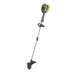
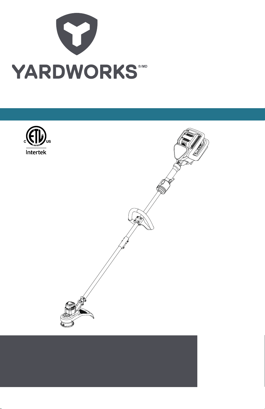
13” (33 CM) CORDLESS GRASS TRIMMER
3026035
model no. 060-1983-0 | contact us: 1.866.523.5218model no. 060-1983-0 | contact us: 1.866.523.5218
2

model no. 060-1983-0 | contact us: 1.866.523.5218 model no. 060-1983-0 | contact us: 1.866.523.5218
3
model no. 060-1983-0 | contact us: 1.866.523.5218
Introduction 4
Safety Instructions and Symbols 5
Product Specications 9
Product Diagram 10
Assembly 11
Operation 12
Maintenance 18
Storage 18
Troubleshooting 19
Exploded View 20
Parts List 21
Warranty 22
Table of Contents
model no. 060-1983-0 | contact us: 1.866.523.5218
4
Introduction
INTRODUCTION
Congratulations on your purchase of your new Yardworks
®
tool. It has been designed, engineered
and manufactured to give you the best possible dependability and performance.
Should you experience any problem you cannot easily remedy, please contact our Yardworks
®
customer service line at 1.866.523.5218.
PLEASE READ AND RETAIN THIS INSTRUCTION MANUAL. These instructions will enable you to
assemble and maintain your appliance properly. ALWAYS observe the “SAFETY RULES”.
The instruction manual was designed to conveniently help you get your purchase ready to use so
there’s less risk of damaging it and to provide you with enough information for you to get familiar with
your product’s controls and features and to operate it safely.
Please do not operate garden equipment near children. This could
lead to severe injury or death.
Model number:
Serial number:
Date of purchase (MM/DD/YYYY):
Notes:
Please read this manual carefully and make sure you understand the instructions
before using the machine.
SAFETY FIRST
CAUTION: The operation of lawn equipment can
result in foreign objects thrown into the eyes, which
can result in SEVERE EYE INJURY. ALWAYS wear
safety glasses or eye shields while operating your
lawn equipment or performing any adjustments or
repairs. We recommend standard safety glasses or a
wide vision safety mask worn over spectacles.

model no. 060-1983-0 | contact us: 1.866.523.5218 model no. 060-1983-0 | contact us: 1.866.523.5218
5
Important Safety Instructions
WARNING: Read all safety warnings and instructions. Failure to
follow the warnings and instructions may result in electric shock,
re and/or serious injury.
FOR ALL APPLIANCES
• Avoid dangerous environments — do not
use appliances in damp or wet locations.
• Don’t use in rain.
• Keep children away — all people and
pets should be kept at a distance from
the work area.
• Dress properly — do not wear loose
clothing or jewellery. They can be
caught in moving parts. Wear protective
clothing; use of work gloves, long
pants, a long-sleeved shirt and safety
footwear is recommended when working
outdoors. Wear protective hair covering
to contain long hair.
• Use safety glasses — always use face
or dust mask if the area in which you are
working is dusty.
• Use the right appliance — do not use
appliance for any job except that for
which it is intended.
• Do not force appliance — it will do the
job better and with less likelihood of a
risk of injury at the rate for which it was
designed.
• Do not overreach — keep proper footing
and balance at all times.
• Stay alert. Use common sense. Do not
operate appliance when you are tired or
under the inuence of drugs, alcohol or
medication.
• When not in use, appliances should be
stored indoors in dry places out of reach
of children.
• Maintain appliance with care. Follow
instructions for lubricating and changing
accessories. Keep handles dry, clean,
and free from oil and grease.
• Check damaged parts. Before using the
appliance, make sure the safety guards
are intact. Never use a tool without its
safety guard. Check the alignment of the
moving parts, the binding of the moving
parts. Check for broken or defective
parts that can affect the safe operation
of your tool. A guard or other part that is
damaged should be properly repaired
or replaced by an authorized service
centre unless indicated elsewhere in this
manual.
1. FOR ALL BATTERY-OPERATED
GARDENING APPLIANCES:
1. Prevent unintentional starting. Ensure
the switch is in the off-position before
connecting to battery pack, picking up
or carrying the appliance. Carrying the
appliance with your nger on the switch
or energizing appliance that has the
switch on invites accidents.
2. Disconnect the battery pack from
the appliance before making any
adjustments, changing accessories,
or storing appliance. Such preventive
safety measures reduce the risk of
starting the appliance accidentally.
3. Recharge only with the charger specied
by the manufacturer. A charger that is
suitable for one type of battery pack
may create a risk of re when used with
another battery pack.
4. Use appliances only with specically
designated battery packs. Use of any
other battery packs may create a risk of
injury and re.
5. When battery pack is not in use, keep
it away from other metal objects, like
paper clips, coins, keys, nails, screws
or other small metal objects, that can
make a connection from one terminal to
another. Shorting the battery terminals
together may cause burns or a re.
6. Under abusive conditions, liquid may be
ejected from the battery; avoid contact.
If contact accidentally occurs, ush
with water. If liquid contacts eyes, seek
Safety Instructions

model no. 060-1983-0 | contact us: 1.866.523.5218
6
Safety Instructions
additional medical help. Liquid ejected
from the battery may cause irritation or
burns.
7. Do not use a battery pack or appliance
that is damaged or modied. Damaged
or modied batteries may exhibit
unpredictable Canadian spelling resulting
in re, explosion or risk of injury.
8. Do not expose a battery pack
or appliance to re or excessive
temperature. Exposure to re or
temperature above 130°C ( 266°F) may
cause an explosion.
9. Follow all charging instructions and do
not charge the battery pack or appliance
outside of the temperature range
specied in the instructions. Charging
improperly or at temperatures outside
of the specied range may damage the
battery and increase the risk of re.
10. Have servicing performed by a qualied
repair person using only identical
replacement parts. This will ensure that
the safety of the product is maintained.
11. Do not modify or attempt to repair
the appliance or the battery pack (as
applicable) except as indicated in the
instructions for use and care.
ADDITIONAL SAFETY RULES FOR GRASS
TRIMMER
1. Keep guards in place and in good
working order.
2. Keep hands and feet away from cutting
area.
3. Do not use heavier trimmer lines than
recommended in this manual.
4. Do not use line materials of other types
– for example, metal wire, rope, and the
like.
SAFETY WARNINGS FOR BATTERY PACK
a) Do not dismantle, open or shred
battery pack.
b) Do not expose battery pack to heat or
re. Avoid storage in direct sunlight.
c) Do not short-circuit a battery pack. Do
not store battery packs haphazardly
in a box or drawer where they may
short-circuit each other or be short-
circuited by other metal objects. When
battery pack is not in use, keep it away
from other metal objects, like paper clips,
coins, keys, nails, screws or other small
metal objects, that can make a connection
from one terminal to another. Shorting
the battery terminals together may cause
burns or re.
d) Do not remove battery pack from its
original packaging until required for
use.
e) Do not subject battery pack to
mechanical shock.
f) In the event of battery leaking, do not
allow the liquid to come in contact with
the skin or eyes. If contact has been
made, wash the affected area with
copious amounts of water and seek
medical advice.
g) Observe the plus (+) and minus
(–) marks on the battery back and
equipment and ensure correct use.
h) Do not use any battery pack which
is not designed for use with the
equipment.
i) Keep battery pack out of the reach of
children.
j) Seek medical advice immediately if a
cell or battery has been swallowed.
k) Always purchase the battery
pack recommended by the device
manufacturer for the equipment.
l) Keep battery pack clean and dry.
m) Wipe the battery pack terminals with a
clean, dry cloth if they become dirty.
n) Battery pack needs to be charged
before use. Always use the correct
charger and refer to the manufacturer’s
instructions or equipment manual for
proper charging instructions.
o) Do not leave battery pack on prolonged
charge when not in use.
p) After extended periods of storage,
it may be necessary to charge and
discharge the battery pack several
times to obtain maximum performance.
model no. 060-1983-0 | contact us: 1.866.523.5218 model no. 060-1983-0 | contact us: 1.866.523.5218
7
q) The battery pack gives its best
performance when it is operated at
normal room temperature (20°C ±
5°C/68°F ± 9°F).
r) When disposing of battery packs,
keep battery packs of different
electrochemical systems separate
from each other.
s) Recharge only with the charger
specied by
Yardworks
®
. Do not
use any charger other than that
specically provided for use with the
equipment. A charger that is suitable
for one type of battery pack may create
a risk of re when used with another
battery pack.
t) Retain the original product literature
for future reference.
u) Use only the battery pack in the
application for which it was intended.
v) Remove the battery pack from the
equipment when not in use.
w) Dispose of properly.
Information for radiated emission
This device complies with Canadian ICES-
001.
This device complies with Part 15 of the FCC
Rules.
Operation is subject to the following two
conditions:
(1) This device may not cause harmful
interference, and
(2) This device must accept any interference
received, including interference that may
cause undesired operation.
NOTE: This equipment has been tested and
found to comply with the limits for a Class B
digital device, pursuant to Part 15 of the FCC
Rules.
These limits are designed to provide
reasonable protection against harmful
interference in a residential installation. This
equipment generates, uses and can radiate
radio frequency energy and, if not installed
and used in accordance with the instructions,
may cause harmful interference to radio
communications.
However, there is no guarantee that
interference will not occur in a particular
installation. If this equipment does cause
harmful interference to radio or television
reception, which can be determined by
turning the equipment off and on, the user is
encouraged to try to correct the interference
by one or more of the following measures:
• Reorient or relocate the receiving
antenna.
• Increase the separation between the
equipment and receiver.
• Connect the equipment into an outlet on
a circuit different from that to which the
receiver is connected.
• Consult the dealer or an experienced
radio/TV technician for help.
Safety Instructions
Warning: Changes or modications to this unit not expressly approved by
the party responsible for compliance could void the user’s authority to
operate the equipment.
model no. 060-1983-0 | contact us: 1.866.523.5218
8
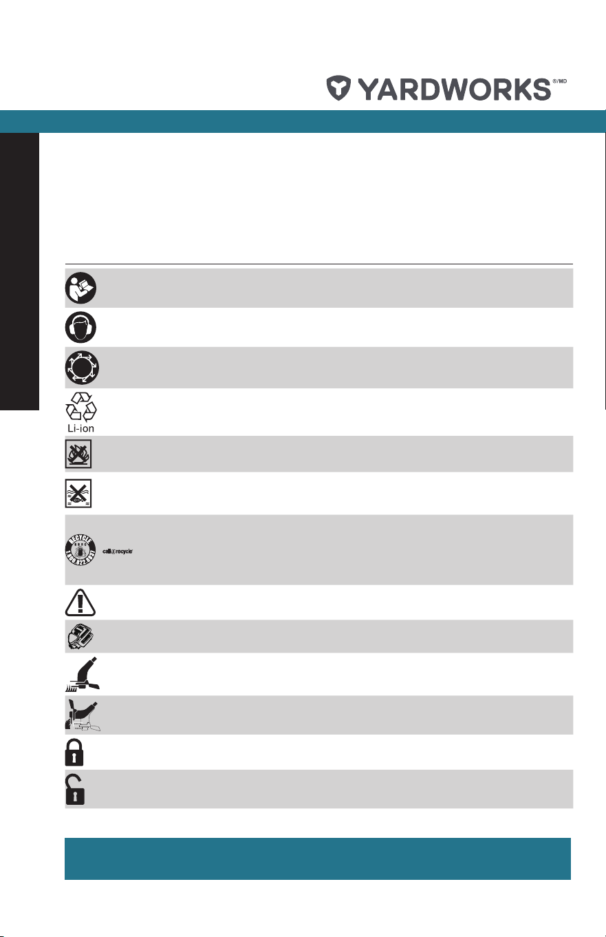
Symbol Designation/Explanation
To reduce the risk of injury, user must read instruction manual
Wear ear protection
This part directs thrown objects away from the operator
Li-ion battery; battery must be recycled
Do not burn
Batteries may enter water cycle if disposed improperly, which can be
hazardous for ecosystem. Do not dispose of waste batteries as unsorted
municipal waste.
Yardworks
®
Canada
has established a partnership with the RBRC
Corporation to recycle any
Yardworks
®
batteries with the RBRC-
call2recycle seal. For environmental protection, please do not discard
batteries in the trash. After the battery’s life cycle is ended, please call
1-800-822-8837 for a free service that will properly dispose of the battery.
Warning
Make sure the battery is removed prior to changing accessories
Trimming
Edging
Lock
Unlock
Some of the following symbols may be used on this product. Please study them and learn
their meaning. Proper interpretation of these symbols will allow you to operate the product
effectively and safely.
SAVE THESE INSTRUCTIONS!
Symbols
model no. 060-1983-0 | contact us: 1.866.523.5218 model no. 060-1983-0 | contact us: 1.866.523.5218
9
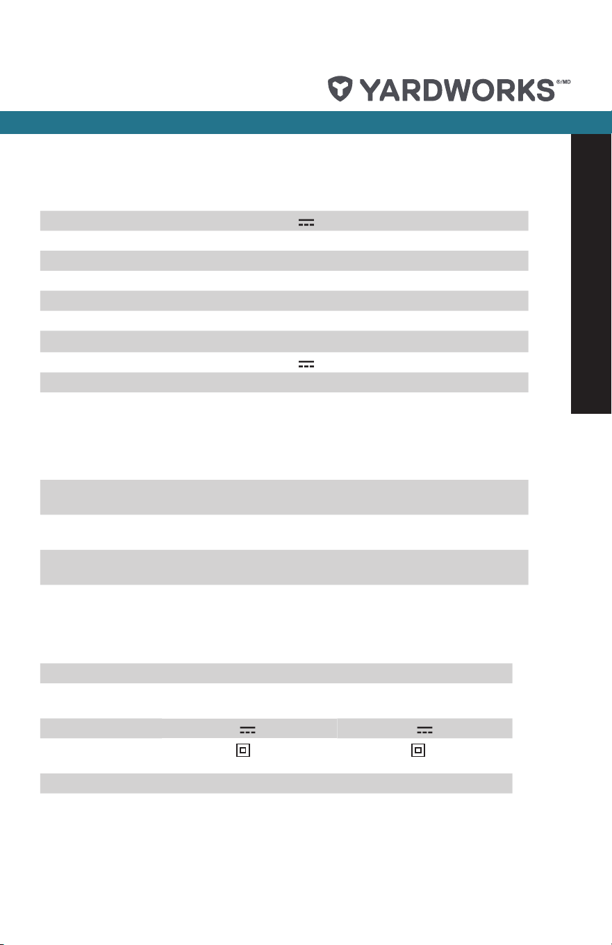
PRODUCT SPECIFICATIONS
Voltage 48 V
No Load Speed 7000/min
Cutting Diameter 13” (33 cm)
Line Diameter 0.080” (2.0 mm)
Line Length 2x8ft (4.9 m)
Battery Capacity (060-1987-2) 2.0 Ah
Charger Input (060-1990-2) 120 V~, 60 Hz, 110 W
Charger Output (060-1990-2) 48 V
, 2 A
Charging Time 1 hr
Machine Weight 11 lb (5 kg)
SUITABLE BATTERY PACKS
Item
Number
060-1987-2
ABP4830SH
060-1988-0
ABP4850SH
060-1989-8
Battery
Capacity
2.0 Ah 3.0 Ah 4.0 Ah 5.0 Ah 6.0 Ah
Included Not
included
Not
included
Not
included
Not
included
SUITABLE CHARGERS
Item Number 060-1990-2 060-1992-8
Charger Input 120 V~, 60 Hz,
110 W
120 V~, 60 Hz,
320 W
Charger Output 48 V
, 2 A 48 V , 6 A
Charger
Protection Class
/II /II
Included Not included
Product Specications
model no. 060-1983-0 | contact us: 1.866.523.5218
10
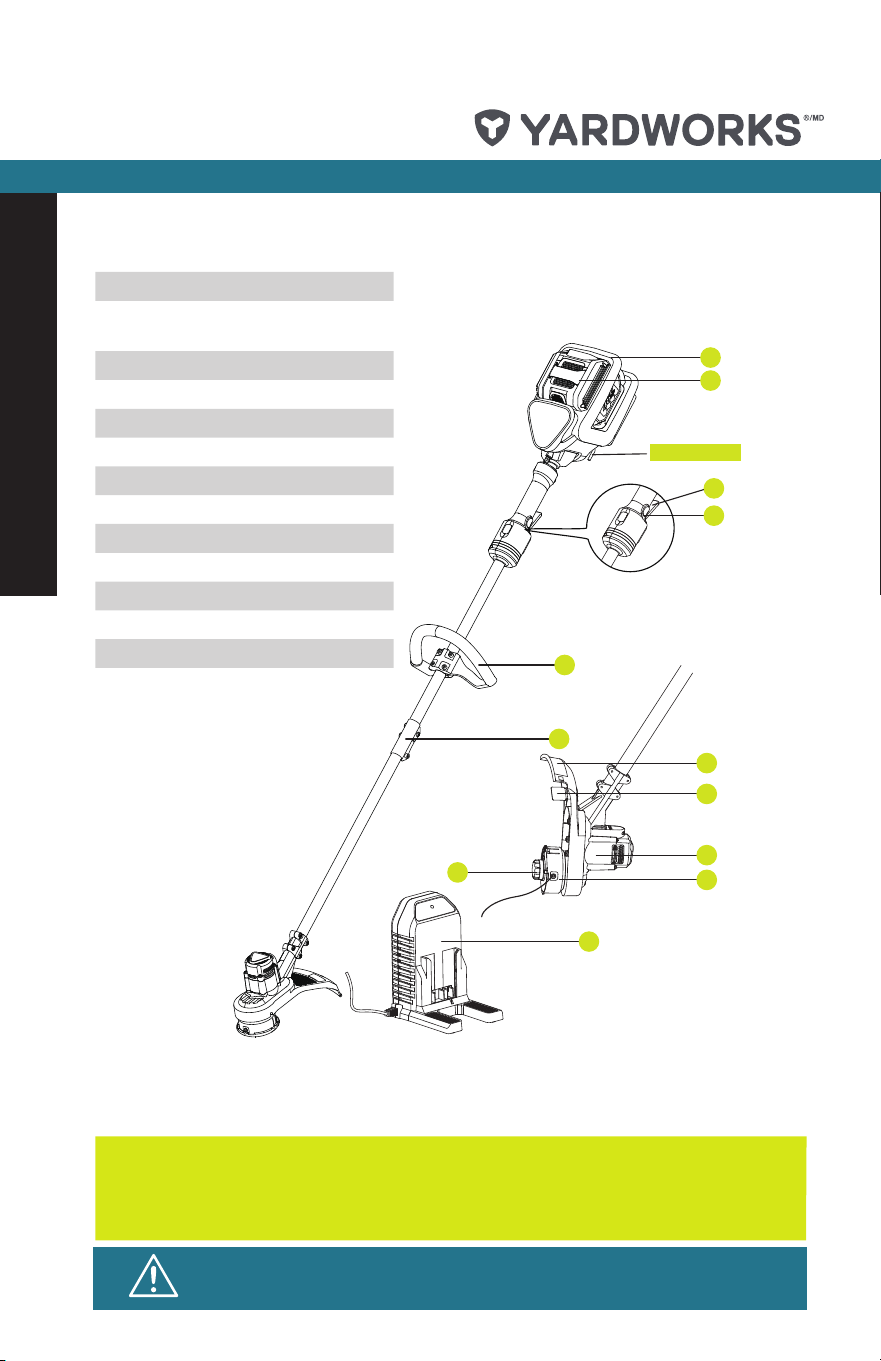
Product Diagram
We recommend that you purchase your accessories listed in the above
list from the same store that sold you the tool. Refer to the accessory
packaging for further details. Store personnel can assist you and offer
advice.
5
7
8
9
10
4
1
2
3
11
6
12
Tool storage
1. Battery pack (060-1987-2)
2. Battery pack release
button
3. On/Off switch
4. Lock-off button
5. Auxiliary handle
6. Connector
7. Safety guard
8. Line cutter
9. Trimmer head
10. Spool
11. Bump knob
12. Charger (060-1990-2)
13. Wrench (Fig. A1)
14. Screws (Fig. B)
WARNING: any other accessory or attachment may increase the risk
of injury.
model no. 060-1983-0 | contact us: 1.866.523.5218 model no. 060-1983-0 | contact us: 1.866.523.5218
11
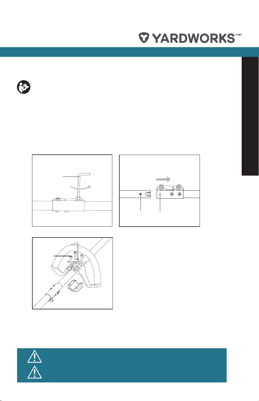
1. ASSEMBLING THE UPPER SHAFT AND LOWER SHAFT
1) Loosen the bolt on the connector. (see Fig. A1.)
2) Align and insert the lower shaft directly into the upper shaft. (see Fig. A2.)
3) Position the locking/release button into the guide recess. (see Fig. A2.)
2. ASSEMBLING THE AUXILIARY HANDLE
Place the auxiliary handle onto the shaft from the top, align with the anti-vibration circle on the
shaft, insert the screws into the four holes, and tighten them with the wrench. (see Fig. B.)
To reduce the risk of injury, user must read instruction manual
Intended Use
The machine is intended for the cutting of grass and weeds under bushes, as well as on
slopes and edges that cannot be reached with the lawn mower.
A2
A1
B
E
E
G1
F
G3
G2
H
G4
I2
I1
I4
I3
J1
J2
C2
C1
1
2
1
2
1
1
2
Locking/
Release knob
Guide recess
13
14
30
0
2
1
A2
A1
B
E
E
G1
F
G3
G2
H
G4
I2
I1
I4
I3
J1
J2
C2
C1
1
2
1
2
1
1
2
Locking/
Release knob
Guide recess
13
14
30
0
2
1
Assembly
CAUTION! The machine must not be operated before it has been
assembled completely.
CAUTION! Do not insert the battery until the appliance has been
completely assembled.
model no. 060-1983-0 | contact us: 1.866.523.5218model no. 060-1983-0 | contact us: 1.866.523.5218
12
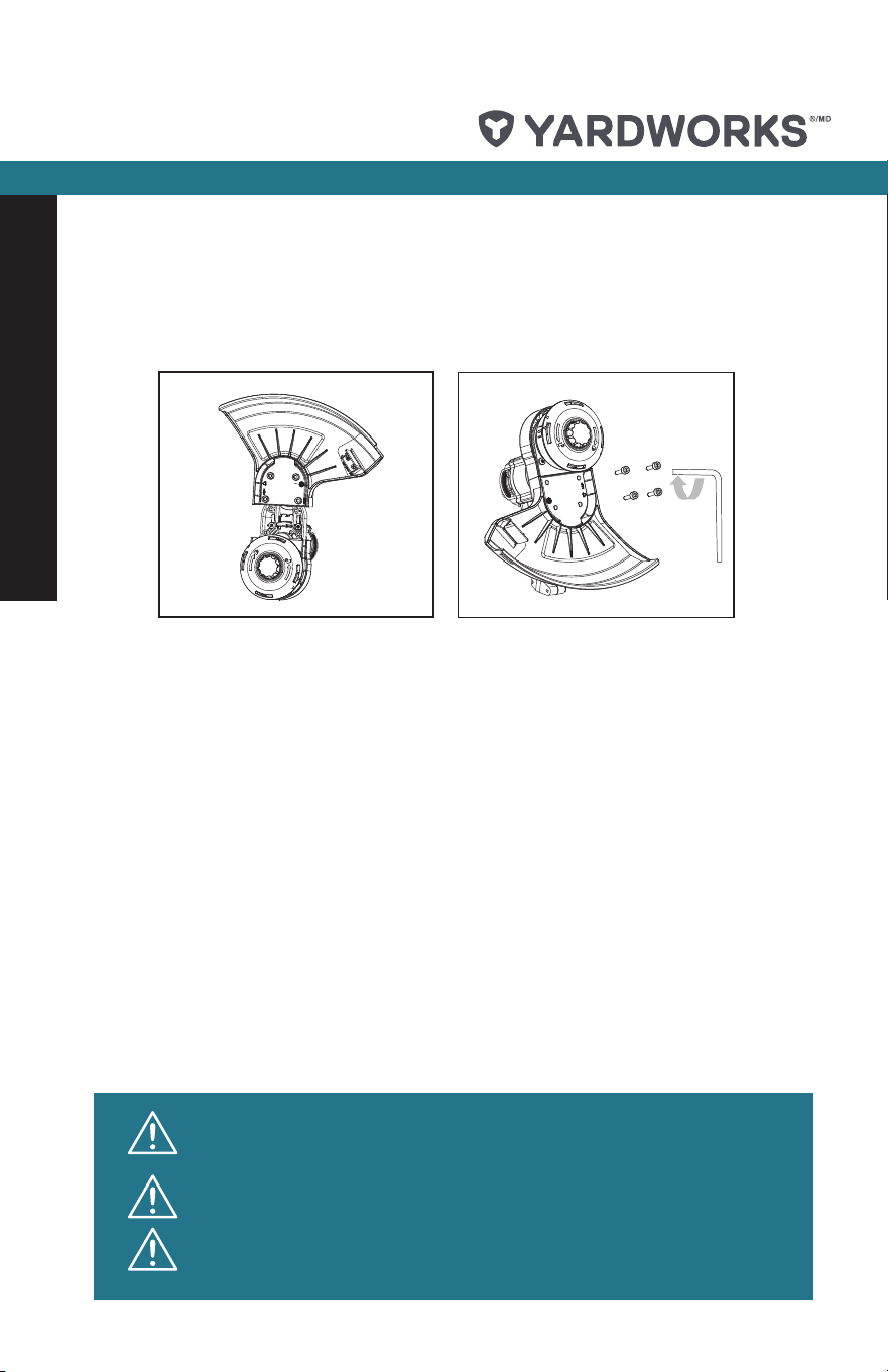
3. Assembling the safety guard
Attach the safety guard to the trimmer head. Align the guard so it slides into the slots located on
the trimmer head. (see Fig. C1.) Secure the safety guard onto the trimmer head with the screw
provided. (see Fig. C2.)
BEFORE OPERATION
1. CHARGING THE BATTERY PACK
IMPORTANT NOTES FOR CHARGING BATTERY
The battery in your new tool is not charged when it leaves the plant; therefore, it must be fully charged
before using the rst time.
NOTE: If the battery pack is very hot, remove the battery from the charger and allow it to cool to
ambient temperature before attempting to recharge.
To prevent damage to the battery pack, please charge the battery to full or no less than half charge
before storage.
If the tool will not be used for long periods of time, charge the battery every 3-6 months.
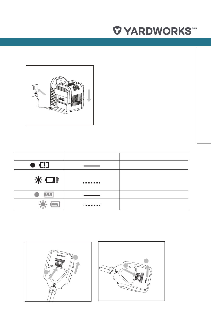
CHARGING PROCEDURE (SEE FIG. D)
1) Plug the charger into an appropriate outlet.
2) Slide the battery pack into the charger; the light will begin ashing green to indicate the charging
process has started.
3) When charging is completed, the light will turn solid green. The pack is now fully charged; unplug
the charger and remove the battery pack.
Operation
WARNING:When battery charge runs out after continuous use or
exposure to direct sunlight or heat, allow time for the battery to cool
down before re-charging to achieve the full charge.
WARNING! Use caution when assembling the safety guard as the
guard has a very sharp line cutter.
WARNING! Never operate the tool without the guard properly in place.
Use of the unit without having installed the guard may result in injury.
A2
A1
B
E
E
G1
F
G3
G2
H
G4
I2
I1
I4
I3
J1
J2
C2
C1
1
2
1
2
1
1
2
Locking/
Release knob
Guide recess
13
14
30
0
2
1
model no. 060-1983-0 | contact us: 1.866.523.5218 model no. 060-1983-0 | contact us: 1.866.523.5218
13
model no. 060-1983-0 | contact us: 1.866.523.5218
2. INSTALLING AND REMOVING THE BATTERY PACK
Slide the battery pack into tool’s battery port. A simple push and slight pressure will be
sufcient. (See Fig. E1.)
Press the battery pack latch and remove the battery pack from the tool. (See Fig. E2.)
Operation
D
Light ON/ Flash Status
Red on
Defective battery.
Red ash
Battery Temperature Protection.
The temperature of battery pack is
less than 0
o
C (32
o
F) or more than
40
o
C (104
o
F).
Green on
Fully charged.
Green ash
Charging.
CHARGING INDICATOR
This charger is designed to detect some problems that can arise with battery packs.
Indicator lights indicate problems (see table below).
A2
A1
C2
C1
B
E1
E2
G
F
H2
H1
H4
H3
J1
I
J3
J2
K2
J4
K1
LOW
High
1
2
1
2
1
2
14
15
30
0
1
2
3
2
1
model no. 060-1983-0 | contact us: 1.866.523.5218
14
WARNING: Always wear eye protection. Never lean over the
trimmer head. Rocks or debris can ricochet or be thrown into
eyes and face and cause blindness or other serious injury.
WARNING: Make sure that line is fed out before operation. Make sure
motor is up to full speed before trimming.
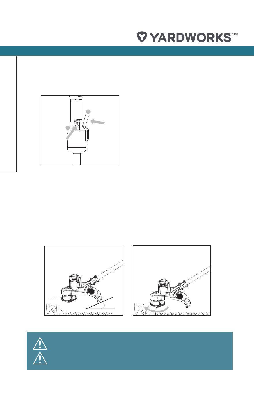
1. SWITCH ON/OFF
To switch on, press the lock-off button rst, then the On/Off Switch. (See Fig. F.)
To switch off, release the On/Off Switch.
2. TRIMMING
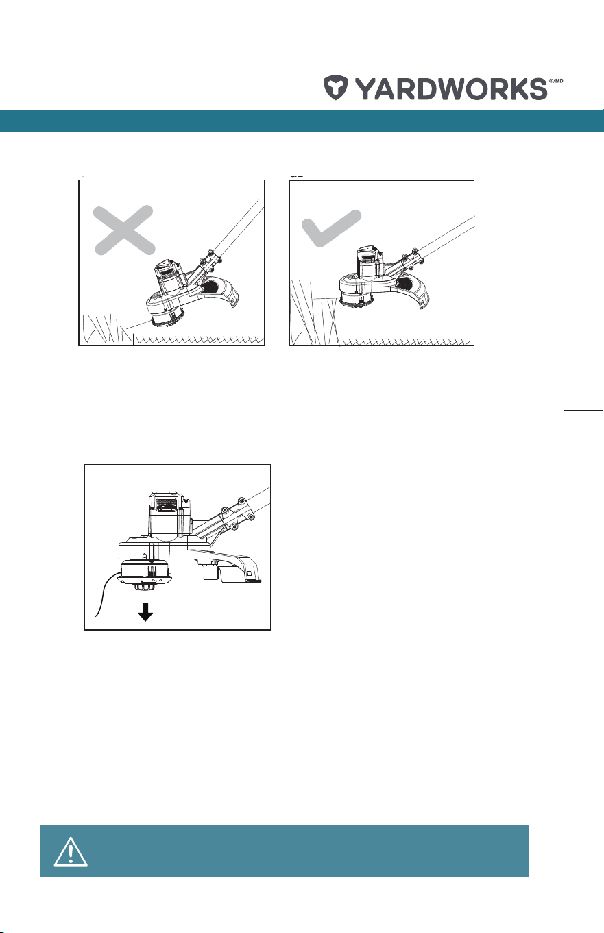
1) Keep the trimmer head at an angle of about 30° to the ground when trimming. (See Fig. G1.)
2) Do not cut wet grass because it tends to stick to the trimmer head and guard, prevents
proper discharge of grass clippings, and could cause you to slip and fall.
3) Regularly remove clippings and dirt around the trimmer head. Ensure the trimmer is
switched off.
4) Work rhythmically; stand rmly with your feet apart. Cut from right to left so the trimmings
will be thrown away from the work area. (see Fig. G2.)
5) When cutting longer/high grass, please make sure that you cut it down in 2 to 3 stages.
(see Fig. G3, G4.).
6) Do not move the trimmer too fast as this will result in ineffective cutting and possible damage.
A2
A1
B
E
E
G1
F
G3
G2
H
G4
I2
I1
I4
I3
J1
J2
C2
C1
1
2
1
2
1
1
2
Locking/
Release knob
Guide recess
13
14
30
0
2
1
A2
A1
B
E
E
G1
F
G3
G2
H
G4
I2
I1
I4
I3
J1
J2
C2
C1
1
2
1
2
1
1
2
Locking/
Release knob
Guide recess
13
14
30
0
2
1
A2
A1
B
E
E
G1
F
G3
G2
H
G4
I2
I1
I4
I3
J1
J2
C2
C1
1
2
1
2
1
1
2
Locking/
Release knob
Guide recess
13
14
30
0
2
1
Operation
model no. 060-1983-0 | contact us: 1.866.523.5218 model no. 060-1983-0 | contact us: 1.866.523.5218
15
Operation
3. ADJUSTING CUTTING LINE LENGTH—AUTOMATIC BUMP LINE FEED
The trimmer head allows the operator to release more cutting line without stopping the
motor. As line becomes frayed or worn, additional line can be released by lightly tapping
the bump knob on the ground while operating the trimmer. (see Fig. H.)
NOTE: Line release will become more difcult if the cutting line becomes too dull.
WARNING: Do not remove or alter the line-cutting blade
assembly. Excessive line length will be cut to suitable length.
A2
A1
B
E
E
G1
F
G3
G2
H
G4
I2
I1
I4
I3
J1
J2
C2
C1
1
2
1
2
1
1
2
Locking/
Release knob
Guide recess
13
14
30
0
2
1
A2
A1
B
E
E
G1
F
G3
G2
H
G4
I2
I1
I4
I3
J1
J2
C2
C1
1
2
1
2
1
1
2
Locking/
Release knob
Guide recess
13
14
30
0
2
1
A2
A1
B
E
E
G1
F
G3
G2
H
G4
I2
I1
I4
I3
J1
J2
C2
C1
1
2
1
2
1
1
2
Locking/
Release knob
Guide recess
13
14
30
0
2
1
model no. 060-1983-0 | contact us: 1.866.523.5218
16
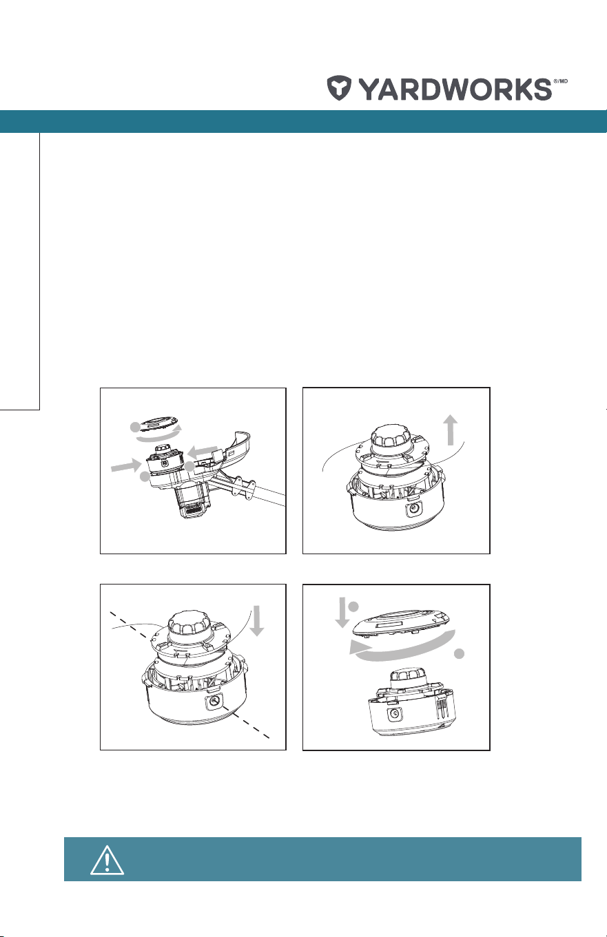
4. TO REPLACE THE SPOOL AND LINE
1) For your convenience, it is recommended you buy a replacement spool with line.
2) Press and hold in the two cap release latches. Loosen the cap by rotating it counter-
clockwise. Pull cap away from the spool holder. (see Fig. I1.)
3) Remove old spool. (see Fig. I2.)
4) Place new spool into cutting head. Release one line from cleat and feed line through
eyelet. (see Fig. I3.)
5) Replace the cap on the spool holder and turn the cap clockwise to tighten. (see Fig. I4.)
NOTE: If required, line can be fed out manually. Gently pull out the 2 lines out until the lines
reach the line cutter. If the line extends past the line cutter, too much line has been fed out. If
too much line is fed out, remove the spool cap and click spool counter-clockwise until the line
is at the desired length.
A2
A1
B
E
E
G1
F
G3
G2
H
G4
I2
I1
I4
I3
J1
J2
C2
C1
1
2
1
2
1
1
2
Locking/
Release knob
Guide recess
13
14
30
0
2
1
A2
A1
B
E
E
G1
F
G3
G2
H
G4
I2
I1
I4
I3
J1
J2
C2
C1
1
2
1
2
1
1
2
Locking/
Release knob
Guide recess
13
14
30
0
2
1
A2
A1
B
E
E
G1
F
G3
G2
H
G4
I2
I1
I4
I3
J1
J2
C2
C1
1
2
1
2
1
1
2
Locking/
Release knob
Guide recess
13
14
30
0
2
1
NOTE: Remove battery prior to replacing the spool and line.
Operation
model no. 060-1983-0 | contact us: 1.866.523.5218 model no. 060-1983-0 | contact us: 1.866.523.5218
17
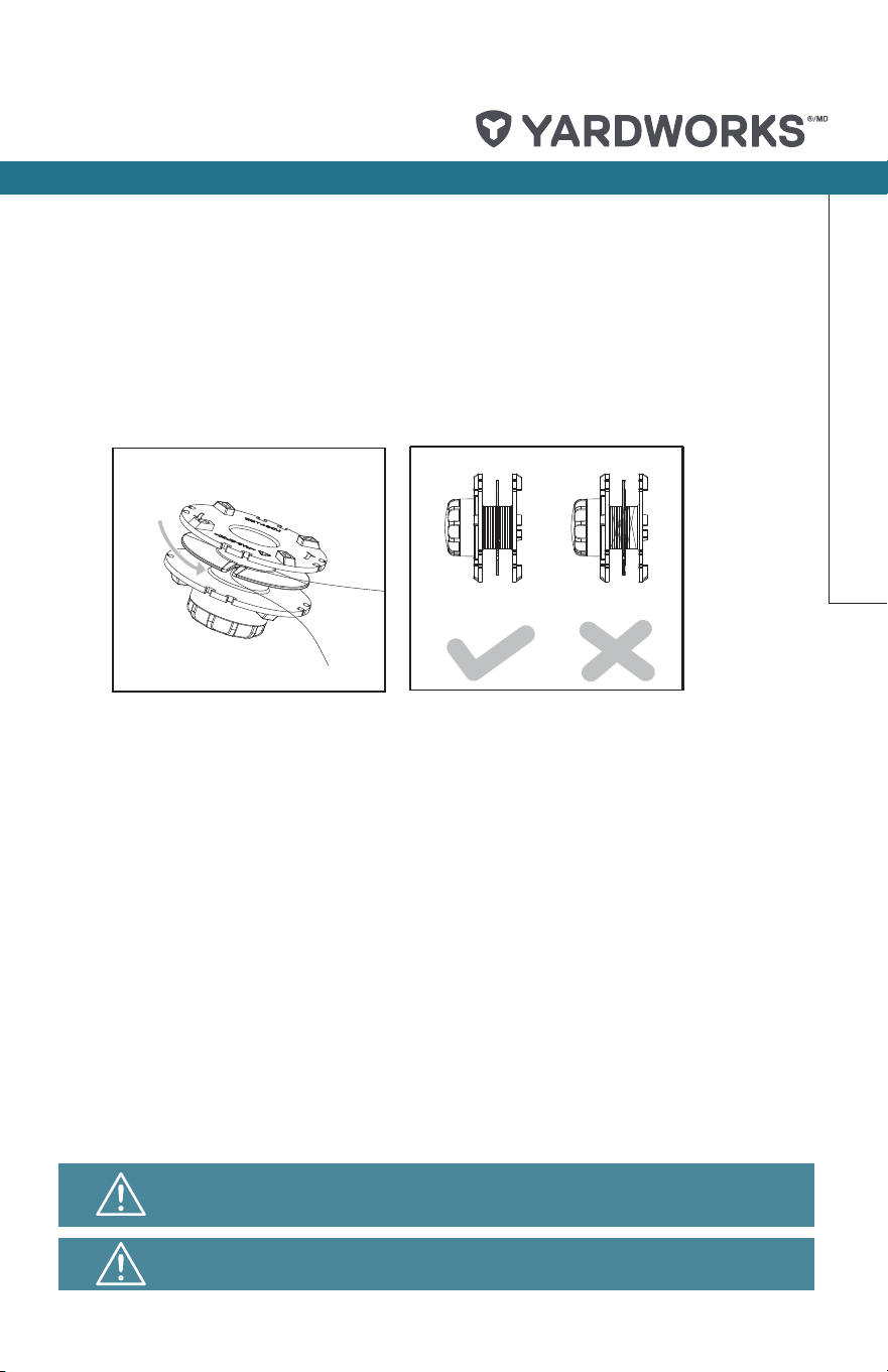
5. TO REPLACE THE LINE ON THE SPOOL
1) Cut a piece of line approximately 16’ (4.9 m) long.
2) Insert the centre point of line into the notch in the middle section of the spool and wind the line
in a clockwise direction as shown. (see. Fig. J1.)
3) Care should be taken to ensure that the line is neatly coiled on the spool. Failure to do so will
impair the efciency of the automatic bump line feed. (see. Fig. J2.)
4) Fit the spool as described in “To Replace the Spool and Line”.
WARNING! Your trimmer is designed to only use line with a
maximum diameter of 0.08” (2 mm).
Always remove the battery pack from your trimmer after use.
A2
A1
B
E
E
G1
F
G3
G2
H
G4
I2
I1
I4
I3
J1
J2
C2
C1
1
2
1
2
1
1
2
Locking/
Release knob
Guide recess
13
14
30
0
2
1
Operation

model no. 060-1983-0 | contact us: 1.866.523.5218
18
MAINTENANCE
Always check the product prior to use for any damage.
After use, disconnect the battery from the tool and check for damage.
Your power tool requires no additional lubrication or maintenance. There are no user-
serviceable parts in your power tool. Never use water or chemical cleaners to clean your
power tool. Wipe clean with a dry cloth. Always store your power tool in a dry, room-
temperature location. Keep the motor ventilation slots clean. Keep all working controls free of
dust.
For Battery Tools
The ambient temperature range for the use and storage of tool and battery is 0 to 45℃ (32 to
113
o
F).
The recommended ambient temperature range for the charging system during charging is
0 to 40℃ (32 to 104
o
F).
It is recommended that the battery be stored indoors for the winter months.
STORING YOUR GRASS TRIMMER
TO STORE YOUR GRASS TRIMMER
Store in a dry place where the trimmer and battery can be protected from damage.
MaintenanceStorage

model no. 060-1983-0 | contact us: 1.866.523.5218 model no. 060-1983-0 | contact us: 1.866.523.5218
19
Troubleshooting
The following table gives problems and actions that you can perform if your machine does
not operate correctly. Warning: Switch the machine off and remove the battery prior to any
troubleshooting.
Problems Possible Causes Corrective Action
Trimmer fails to operate.
Battery discharged.
Battery too hot/cold.
Motor is broken.
Internal wiring of machine
damaged.
Recharge battery; also see the content
in charger manual.
Allow to cool/warm.
Contact Yardworks
®
at 1.866.523.5218.
Contact Yardworks
®
at 1.866.523.5218.
Trimmer runs
intermittently.
Motor is broken.
Battery not fully charged.
On/Off switch defective.
Contact Service Agent.
Recharge battery.
Contact Yardworks
®
at 1.866.523.5218.
Excessive vibrations
/noise.
Machine defective.
Line spool is not wound well.
Contact Yardworks
®
at 1.866.523.5218.
Rewind the line. See “To Replace the
Line on the Spool’’.
Cutting time per battery
charge too short.
Battery has not been used for
long period or only charged for
short term.
Grass too high.
Battery defective.
Fully charge battery; also see
the content in charger manual.
Cut in stages.
Replace the battery.
Machine does not cut.
Line broken.
Battery not fully charged.
Motor is broken (speed is too
low).
Grass entangled around cutting
head.
Replace the line.
Recharge battery; also see.
the content in charger manual.
Contact Yardworks
®
at 1.866.523.5218.
Remove grass.
Continuous lighting of the
battery charge indicator/
battery not charging.
Battery not (properly) inserted.
Battery contacts contaminated.
Battery defective.
Properly insert battery into battery
charger.
Clean the battery contacts or replace
the battery.
Replace the battery.
Battery charge indicator
does not light up.
Plug of battery charger not
plugged in (properly).
Outlet or mains cable defective.
Battery charger defective.
Insert mains plug (fully) into the socket
outlet.
Check the mains voltage.
Replace the battery charger.
model no. 060-1983-0 | contact us: 1.866.523.5218
20
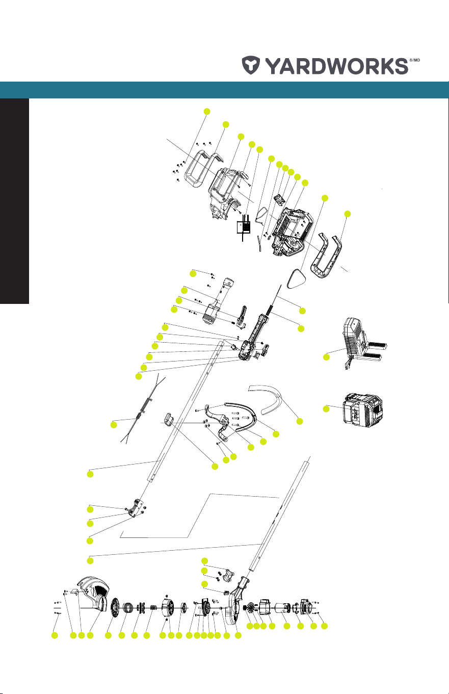
Exploded View
28
27
26
25
24
23
22
21
20
19
18
17
16
15
14
13
12
11
10
9
8
7
6
5
4
3
2
1
47
46
45
44
43
42
41
40
39
38
37
36
35
34 33
32
31
30
29
60
59
58
57
56
55
54
53
52
51
50
49
48
62
63
64
65
66
67
68
61
69

model no. 060-1983-0 | contact us: 1.866.523.5218 model no. 060-1983-0 | contact us: 1.866.523.5218
21
Parts List
NO.
Part Description
Quantity
1
Self-Tapping Screw
4
2
Rear Cover
1
3
Bafe
1
4
Motor
1
5
Housing
1
6
Screw
2
7
Fan
1
8
Gear
1
9
Flange
1
10
Gear Box Body
1
11
Flange
1
12
Self Tapping Screw
4
13
Cover
1
14
Self Tapping Screw
4
15
Gear
1
16
Gear Cover
1
17
Outpput Shaft
1
18
Self Tapping Screw
3
19
Inner Flange
1
20
Cutting Head
1
21 Rivet 2
22 Compression Spring 1
23
Spool
1
24
Cutting Line
1
25
Cutting Head Cover
1
26
Guard
1
27
Cutting Blade
1
28
Self Tapping Screw
2
29
Self Tapping Screw
4
30
Aluminium_tube
1
31
Self Tapping Screw
2
32 Connect Sheath 1
33 Screw 1
34 Aluminium_tube 1
35 Coiled Cable 1
36 Left_handle 1
37 Cover 1
38 Lock Knob 1
39 Switch 1
40 Compression Spring 1
41 Self Tapping Screw 2
42 Compression Spring 1
43 Trigger 1
44 Right_handle 1
45 Self Tapping Screw 7
46 Self Tapping Screw 9
47 Right Side Cover 1
48 Right_battery_support 1
49 Self Tapping Screw 8
50 Protect Control Board 1
51 Torsional Spring 1
52 Spanner 1
53 Self Tapping Screw 2
54 Terminal 1
55 Cord Clamp 1
56 Left_battery_support 1
57 Cover 1
58 Left Side Cover 1
59 Internal Wire 1
60 Corrugated Pipe 1
61 TUBE 1
62 Auxiliary Handle 1
63 Screw 4
64 Steady Handle Supper 1
65 Nut 4
66 Self Tapping Screw 2
67 Steady Handle Cover 1
68 Battery Pack 1
69 Charger 1

model no. 060-1983-0 | contact us: 1.866.523.5218model no. 060-1983-0 | contact us: 1.866.523.5218
22
!
Always remove or disconnect the battery pack before adjusting, cleaning,
servicing or transporting your appliance.
Made in China. Imported by Yardworks Canada
Toronto, Canada M4S 2B8
FIVE-YEAR LIMITED WARRANTY
For ve (5) years from the date of purchase
within Canada, YARDWORKS CANADA
will, at its option, repair or replace for the
original purchaser, free of charge, any part
or parts found to be defective in material or
workmanship (excludes battery).
For THREE (3) years from the date of
purchase within Canada, YARDWORKS
CANADA will, at its option, repair or replace
for the original purchaser, free of charge, any
battery found to be defective in material or
workmanship.
THIS WARRANTY DOES NOT COVER
1. Any part that has become inoperative
due to misuse, commercial use, abuse,
neglect, accident, improper maintenance,
or alteration;
2. The unit, if it has not been operated and/
or maintained in accordance with the
owner’s manual;
3. Normal wear, except as noted below;
4. Routine maintenance items such as
lubricants, blade sharpening; or
5. Normal deterioration of the exterior nish
due to use or exposure.
FULL ONE YEAR (365) DAYS WARRANTY
ON NORMAL WEAR PARTS
Normal wear parts are dened as blade
adaptors, blades, grass bags and tires.
These parts are warranted to the original
purchaser to be free from defects in
material and workmanship for a period of
three hundred and sixty-ve (365) days from
the date of retail purchase.
HOW TO OBTAIN SERVICE
Warranty service is available by calling
the toll-free helpline at 1.866.523.5218.
The factory will not accept the return of a
complete unit unless prior written permission
has been extended by YARDWORKS
CANADA.
TRANSPORTATION CHARGES
Transportation charges for the movement
of any power equipment unit or attachment
are the responsibility of the purchaser.
The purchaser must pay transportation
charges for any part submitted for
replacement under this warranty unless
such return is requested in writing by
YARDWORKS CANADA.
OTHER WARRANTIES
All other warranties, express or implied,
including any implied warranty of
merchantability is limited in its duration to
that set forth in this express limited warranty.
The provisions as set forth in this warranty
provide the sole and exclusive remedy of
YARDWORKS CANADA obligations arising
from the sale of its products.
Warranty

model no. 060-1983-0 | contact us: 1.866.523.5218 model no. 060-1983-0 | contact us: 1.866.523.5218
23
model no. 060-1983-0 | contact us: 1.866.523.5218
FCC Part 15
Supplier’s Declaration of Conformity
Product Description: 48V 2.0A Charger
Model Number: 060-1990-2
Trade Name: YARDWORKS
®
This device complies with part 15 of the FCC Rules.
Operation is subject to the following two conditions:
(1) This device may not cause harmful interference, and
(2) This device must accept any interference received, including interference that may
cause undesired operation.
Responsible Party:
Positec USA, Inc.
PO Box 681298, Charlotte, NC 28216
Tel: 1 - (866) - 523 - 5218
Fax: (704) 599-6390

Item # 060-1983-0 | contact us: 1.866.523.5218
13” (33 CM) CORDLESS GRASS TRIMMER
1
Quick Start Guide
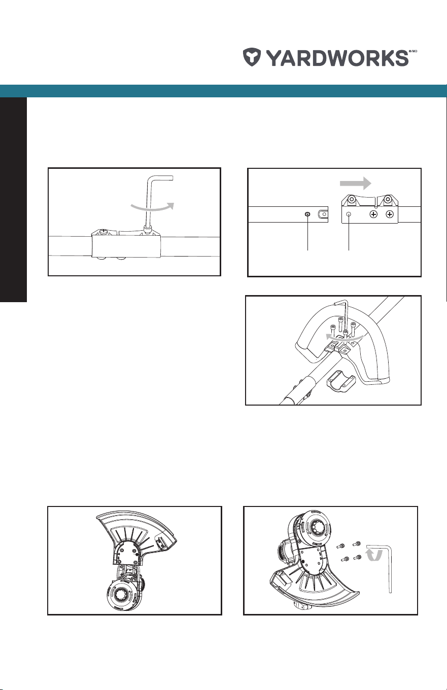
1. ASSEMBLING THE UPPER SHAFT AND LOWER SHAFT
a) Loosen the bolt on the connector. (See Fig. A1.)
b) Align and insert the lower shaft directly into the upper shaft. (See Fig. A2.)
c) Position the locking/release button into the guide recess. (See Fig. A2.)
2. ASSEMBLING THE AUXILIARY HANDLE
Place the auxiliary handle onto the shaft
from the top, align with the anti-vibration
circle on the shaft, screw into four holes, and
tighten it with the wrench. (See Fig. B.)
Locking/
Release knob
Guide recess
A1
B
C1 C2
Locking/
Release knob
Guide recess
A2
* This information is provided for your convenience. It does not replace the instruction manual
and safety instructions. The manual and safety instructions need to be read and understood in
their entirety.
3. ASSEMBLING THE SAFETY GUARD
a) Attach the safety guard to the trimmer head. Align the guard so it slides into the slots located
on the trimmer head. (See Fig. C1.)
b) Secure the safety guard onto the trimmer head with the bolts provided by using the wrench.
(See Fig. C2.)
c) Please put the wrench back to the top notch of grass trimmer after use, so it will not get lost.
(See Fig. C3.)
Item # 060-1983-0 | contact us: 1.866.523.5218 Item # 060-1983-0 | contact us: 1.866.523.5218
13” (33 CM) CORDLESS GRASS TRIMMER
2
Quick Start Guide
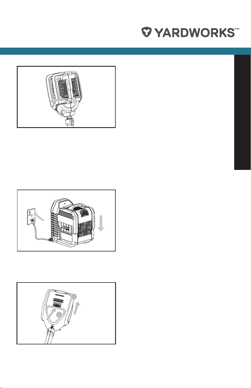
BEFORE OPERATION
1. CHARGING PROCEDURE (SEE FIG. D.)
a) Plug the charger into an appropriate outlet.
b) Slide the battery pack into the charger; the light will begin ashing green to indicate the
charging process has started.
c) When charging is completed, the light will turn solid green. The pack is now fully charged;
unplug the charger and remove the battery pack.
1
1
2
2
E
2. INSTALLING AND REMOVING THE BATTERY PACK
Slide the battery pack into tool’s battery port. A simple push and slight pressure will be sufcient.
Press the battery pack latch and remove the battery pack from the tool. (See Fig. E.)
* This information is provided for your convenience. It does not replace the instruction manual
and safety instructions. The manual and safety instructions need to be read and understood in
their entirety.
D
C3