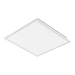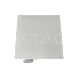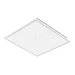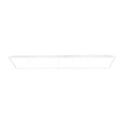
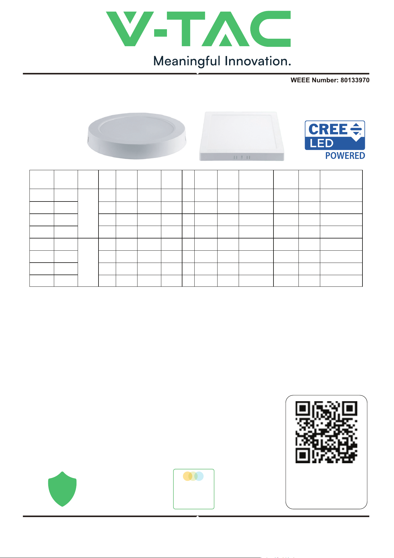
LED BACKLIT SURFACE MOUNTED PANEL
TECHNICAL DATA
INTRODUCTION & WARRANTY
WARNING
INSTRUCTION MANUAL
This product contains a light source of energy eciency class <F/E>', where <F/E> shall be replaced by
the energy eciency class of the contained light source.
Thank you for selecting and buying V-TAC product. V-TAC will serve you the best. Please read these instructions care-
fully before starting the installation and keep this manual handy for future reference. If you have any another query,
please contact our dealer or local vendor from whom you have purchased the product. They are trained and ready to
serve you at the best. The warranty is valid for 6 years from the date of purchase. The warranty does not apply to
damage caused by incorrect installation or abnormal wear and tear. The company gives no warranty against damage
to any surface due to incorrect removal and installation of the product. The products are suitable for 10-12 Hours Daily
operation. Usage of product for 24 Hours a day would void the warranty. This product is warranted for manufacturing
defects only.
• Please make sure to turn o the power before starting the installation.
• Installation must be performed by a certified person.
• If the external flexible cable or cord of this luminaire is damaged, it shall be
exclusively replaced by the manufacturer or his service agent or a similar
qualified person in order to avoid a hazard.
• Method of attachment of the cable or cord such that any replacement can only
be made by the manufacturer, his service agent or similar qualifed person.
• For Indoor use only.
MULTI-LANGUAGE
MANUAL QR CODE
Please scan the QR code
to access the manual in
multiple languages.
IN CASE OF ANY QUERY/ISSUE WITH THE PRODUCT, PLEASE REACH OUT TO US AT: SUPPORT@V-TAC.EU
FOR MORE PRODUCTS RANGE, INQUIRY PLEASE CONTACT OUR DISTRIBUTOR OR NEAREST DEALERS. V-TAC
EUROPE LTD. BULGARIA, PLOVDIV 4000, BUL.L.KARAVELOW 9B
VT-60006CCT
VT-60012CCT
VT-60018CCT
VT-60024CCT
78706
78736
78766
78796
VT-60006CCT
VT-60012CCT
VT-60018CCT
VT-60024CCT
104926
104956
104986
105146
MODEL SKU WATTS
LUMENS
BODY
TYPE
TOTAL
CURRENT
INPUT
VOLTAGE
CRI
LIFE
SPAN
[HOURS]
ON/OFF
CYCLE
[TIMES]
SHAPE
DIMENSION
(LxWxH)
BEAM
ANGLE
IP
RATING
6W
120°
>80
IP20
AC:220-240
50/60Hz
AC:220-240
50/60Hz
AC:220-240
50/60Hz
AC:220-240
50/60Hz
36mA
71mA
103mA
160mA
>15000 121.2x30.6mm
167.4x30.7mm
215.6x30.8mm
288.6x31.2mm
120.8x120.8x30.7mm
167.3x167.3x30.7mm
214x214x31mm
287x287x30.7mm
30,000
>1500030,000
>1500030,000
>1500030,000
ROUND
SQUARE
PLASTIC
120°
>80
IP20
PLASTIC
120°
>80
IP20
PLASTIC
120°
>80
IP20
PLASTIC
12W
18W
24W
630 Lm
1320 Lm
1980 Lm
2640 Lm
6W
120°
>80
IP20
AC:220-240
50/60Hz
AC:220-240
50/60Hz
AC:220-240
50/60Hz
AC:220-240
50/60Hz
36mA
71mA
103mA
160mA
>1500030,000
>1500030,000
>1500030,000
>1500030,000
PLASTIC
120°
>80
IP20
PLASTIC
120°
>80
IP20
PLASTIC
120°
>80
IP20
PLASTIC
12W
18W
24W
630 Lm
1320 Lm
1980 Lm
2640 Lm
6
6 YEAR
WARRANTY*
COLOR
CHANGING
3-IN-1
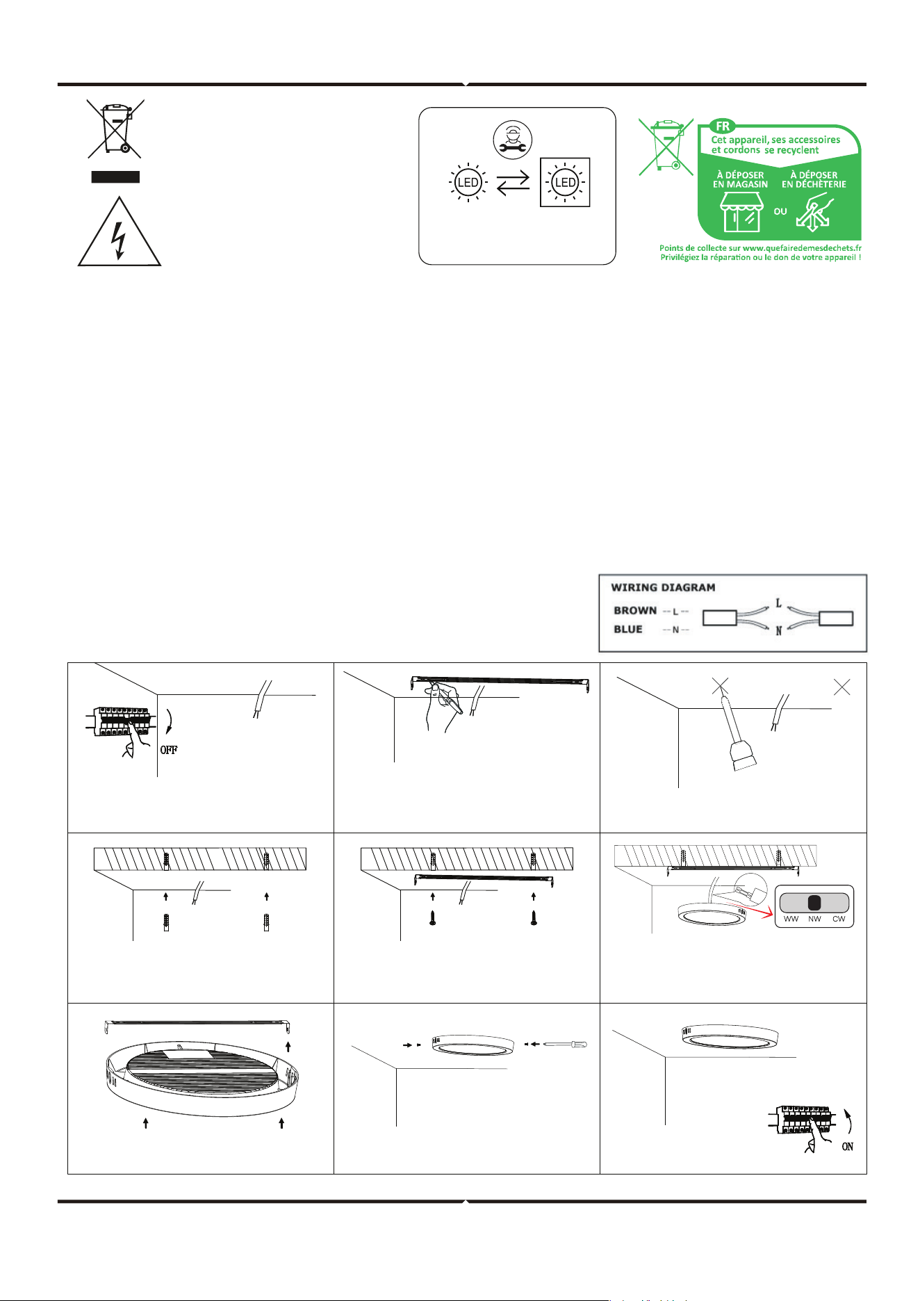
INSTALLATION DIAGRAM
ATTENTION!
USAGE GUIDELINES/MAINTENANCE
MOUNTING
Do not look directly at the LED light beam. Use the product only with the rated voltage or within the specified range.
Do not operate the product if the protective cover is damaged. Avoid using it in adverse conditions such as dust, water,
moisture, vibrations, explosive atmospheres, or chemical fumes. Strong electromagnetic interference may disrupt
product performance.
Perform all maintenance only aer disconnecting the power supply and allowing the product to cool. Clean with a so,
dry cloth only; do not use chemical cleaners. Do not cover the product and ensure adequate airflow, as it may reach
high temperatures during operation.
Read the manual before installation. Installation must be carried out by a qualified electrician. Exercise caution: the
product includes a protective contact/terminal, and failure to connect it may result in electric shock. Refer to the mount-
ing diagram for guidance. Ensure proper mechanical fastening and electrical connection before first use.
ing diagram for guidance. Ensure proper mechanical fastening and electrical connection before first use.
This marking indicates that this
product should not be disposed
of with other household wastes.
Replaceable (LED only)
light source by a professional
Caution, risk of electric shock.
2. Confirm the bracket installation
position.
1.Switch OFF the power before
beginning installation.
3. Drill the mounting hole.
4. Insert the expansion bolt. 5. Secure the included bracket to the
ceiling with screws.
6. Connect the wiring according to the
wiring diagram.
7. Adjust the color temperature using the
CCT switch.
8. Install the panel into the bracket. 9. Fasten the light with screws. 10. Turn on the power
and test the light.
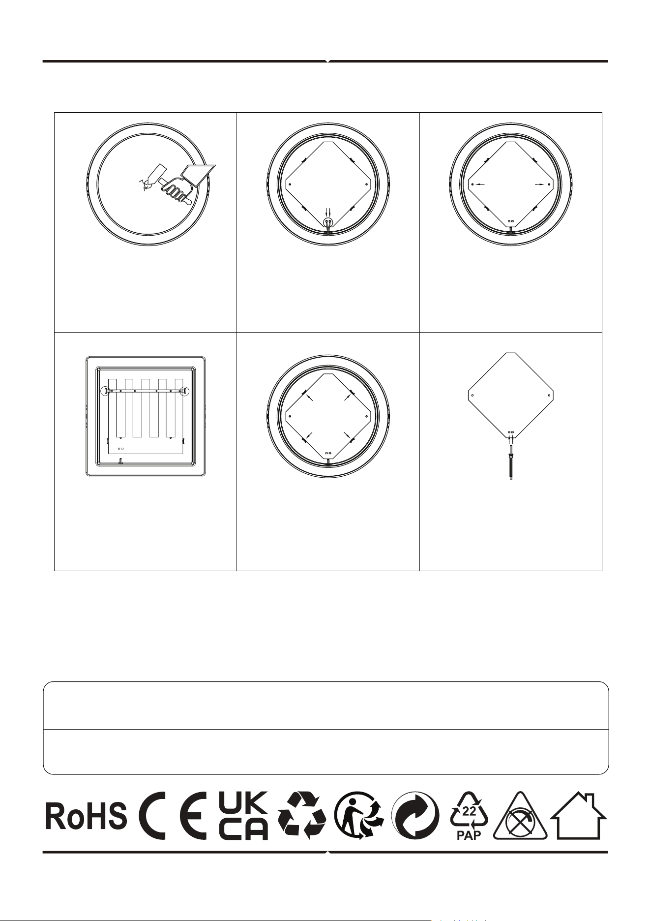
DISASSEMBLY DIAGRAM
(For Market surveillance team only)
Note: Light source removal will void the warranty
V-TAC UK LTD. IN CASE OF ANY QUERY/ISSUE WITH THE PRODUCT PLEASE REACH OUT TO US AT
[email protected] V-TAC, 5A TUNGSTEN PARK, DOWNS ROAD, WITNEY, OXFORDSHIRE, OX29 0AX
V-TAC WEST EUROPE LTD. IN CASE OF ANY QUERY/ISSUE WITH THE PRODUCT, PLEASE REACH OUT TO US AT:
[email protected] FOR MORE PRODUCTS RANGE, INQUIRY PLEASE CONTACT OUR DISTRIBUTOR OR NEAREST
DEALERS. V-TAC WEST EUROPE LTD. GROUND FLOOR, 71 LOWER BAGGOT STREET, DUBLIN 02, IRELAND DO2 P593
1.Power o the unit, tap the center
of the diusion plate with a
pointed tool, and remove the
damaged plate.
4. Push the buckle outward to
release and remove the aluminum
substrate pressing strip from the
bayonet. This step is required only
for the 24W panel light.
2. Disconnect the power wire from
the plug terminal.
5. Push the buckle outward to
release the aluminum substrate,
then remove the light source
board.
6. Insert a two-core cable (18–22
AWG) into the plug-in terminal,
then connect the external power
supply for testing.
3. If there is no hot-melt column or
it is not fused, skip this step. If the
hot-melt column is fused to secure
the aluminum substrate, cut the
fused section with diagonal pliers.