Exterior 600 Compact
user manual
martinarchitectural
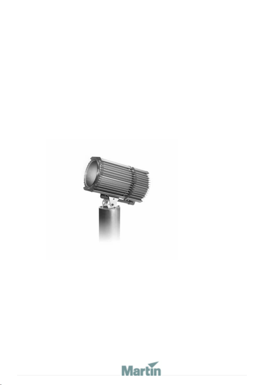
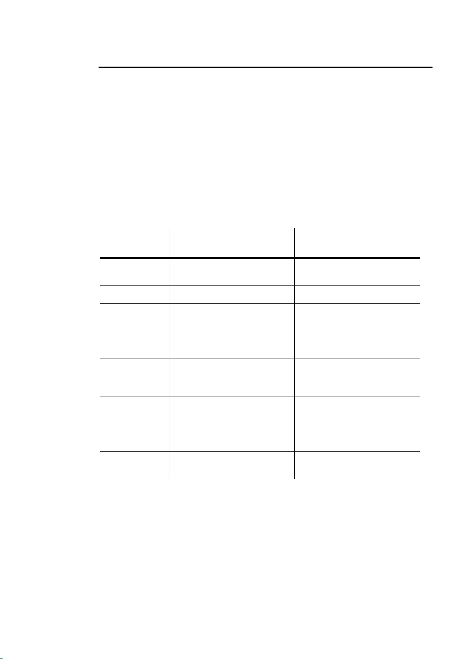
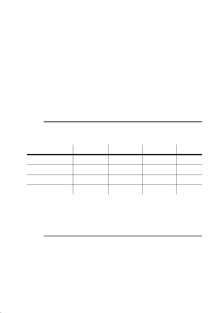
Measurements are in millimeters
576
293
273
375
308
421
© 1999-2005 Martin Professional A/S, Denmark.
All rights reserved. No part of this manual may be reproduced, in any form or by any means, with-
out permission in writing from Martin Professional A/S, Denmark.
Printed in Denmark.
P/N 35000082, Rev F

3
SECTION 1. GETTING STARTED.........................................7
INTRODUCTION . . . . . . . . . . . . . . . . . . . . . . . . . . . . . . . . . . . . . . . 8
Software note. . . . . . . . . . . . . . . . . . . . . . . . . . . . . . . . . . . . . . . . . . . . . . . . 8
Safety information . . . . . . . . . . . . . . . . . . . . . . . . . . . . . . . . . . . . . . . . . . . . 8
INSTALLATION . . . . . . . . . . . . . . . . . . . . . . . . . . . . . . . . . . . . . . . 11
Unpacking . . . . . . . . . . . . . . . . . . . . . . . . . . . . . . . . . . . . . . . . . . . . . . . . . 11
Lamp Installation . . . . . . . . . . . . . . . . . . . . . . . . . . . . . . . . . . . . . . . . . . . . 11
Adjust the beam angle (if required) . . . . . . . . . . . . . . . . . . . . . . . . . . . . . . 11
Fixture installation . . . . . . . . . . . . . . . . . . . . . . . . . . . . . . . . . . . . . . . . . . . 11
AC POWER . . . . . . . . . . . . . . . . . . . . . . . . . . . . . . . . . . . . . . . . . 14
Power configuration . . . . . . . . . . . . . . . . . . . . . . . . . . . . . . . . . . . . . . . . . . 14
Connection to the mains supply. . . . . . . . . . . . . . . . . . . . . . . . . . . . . . . . . 14
DATA LINK . . . . . . . . . . . . . . . . . . . . . . . . . . . . . . . . . . . . . . . . . 19
Cable and junctions . . . . . . . . . . . . . . . . . . . . . . . . . . . . . . . . . . . . . . . . . . 19
Adaptors. . . . . . . . . . . . . . . . . . . . . . . . . . . . . . . . . . . . . . . . . . . . . . . . . . . 20
Building a data link. . . . . . . . . . . . . . . . . . . . . . . . . . . . . . . . . . . . . . . . . . . 21
FIXTURE SETTINGS . . . . . . . . . . . . . . . . . . . . . . . . . . . . . . . . . . . 22
Defining fixture settings using MUM. . . . . . . . . . . . . . . . . . . . . . . . . . . . . . 24
GENERAL OPERATION . . . . . . . . . . . . . . . . . . . . . . . . . . . . . . . . . 27
Lamp operation . . . . . . . . . . . . . . . . . . . . . . . . . . . . . . . . . . . . . . . . . . . . . 27
Cold weather operation . . . . . . . . . . . . . . . . . . . . . . . . . . . . . . . . . . . . . . . 27
The LEDs and fixture operating status. . . . . . . . . . . . . . . . . . . . . . . . . . . . 27
Fixture control methods . . . . . . . . . . . . . . . . . . . . . . . . . . . . . . . . . . . . . . . 28
Color matching Exterior 200s and Exterior 600 Compacts . . . . . . . . . . . . 29
SECTION 2. STAND-ALONE OPERATION ..........................31
STAND-ALONE PROGRAMMING OVERVIEW . . . . . . . . . . . . . . . . . . 32
About scene timing. . . . . . . . . . . . . . . . . . . . . . . . . . . . . . . . . . . . . . . . . . . 33
Synchronizing scene changes for multiple Exterior 600 Compacts . . . . . . 33
Programming methods. . . . . . . . . . . . . . . . . . . . . . . . . . . . . . . . . . . . . . . . 34
PROGRAMMING FROM A PC USING MUM. . . . . . . . . . . . . . . . . . . 35
Getting started . . . . . . . . . . . . . . . . . . . . . . . . . . . . . . . . . . . . . . . . . . . . . . 35
Stand-Alone Settings . . . . . . . . . . . . . . . . . . . . . . . . . . . . . . . . . . . . . . . . . 36
Programming effects in scenes . . . . . . . . . . . . . . . . . . . . . . . . . . . . . . . . . 38
Programming the same stand-alone show on multiple fixtures . . . . . . . . . 39
STAND-ALONE SHOW PLAYBACK . . . . . . . . . . . . . . . . . . . . . . . . . 41

4
Starting show playback automatically at fixture power-on . . . . . . . . . . . . . 41
Scene execution using the optional MC-X . . . . . . . . . . . . . . . . . . . . . . . . . 41
DMX controller override during stand-alone show playback . . . . . . . . . . . 42
SYNCHRONOUS TRIGGERING DURING STAND-ALONE OPERATION . .43
SECTION 3. DMX CONTROL........................................... 45
PREPARING A FIXTURE FOR DMX CONTROL. . . . . . . . . . . . . . . . . .46
DMX address . . . . . . . . . . . . . . . . . . . . . . . . . . . . . . . . . . . . . . . . . . . . . . . 46
DMX lamp off option. . . . . . . . . . . . . . . . . . . . . . . . . . . . . . . . . . . . . . . . . . 47
DMX reset option . . . . . . . . . . . . . . . . . . . . . . . . . . . . . . . . . . . . . . . . . . . . 47
DMX mode . . . . . . . . . . . . . . . . . . . . . . . . . . . . . . . . . . . . . . . . . . . . . . . . . 47
DMX CONTROLLER OPERATION . . . . . . . . . . . . . . . . . . . . . . . . . . .49
Effect operation . . . . . . . . . . . . . . . . . . . . . . . . . . . . . . . . . . . . . . . . . . . . . 50
Lamp . . . . . . . . . . . . . . . . . . . . . . . . . . . . . . . . . . . . . . . . . . . . . . . . . . . . . 51
Color. . . . . . . . . . . . . . . . . . . . . . . . . . . . . . . . . . . . . . . . . . . . . . . . . . . . . . 51
DMX PROTOCOL. . . . . . . . . . . . . . . . . . . . . . . . . . . . . . . . . . . . . .52
SECTION 4. SERVICE AND TROUBLESHOOTING ............... 53
SEAL MAINTENANCE . . . . . . . . . . . . . . . . . . . . . . . . . . . . . . . . . . .54
Gaskets . . . . . . . . . . . . . . . . . . . . . . . . . . . . . . . . . . . . . . . . . . . . . . . . . . . 54
Cable glands . . . . . . . . . . . . . . . . . . . . . . . . . . . . . . . . . . . . . . . . . . . . . . . 55
CLEANING . . . . . . . . . . . . . . . . . . . . . . . . . . . . . . . . . . . . . . . . . .56
Cleaning lenses . . . . . . . . . . . . . . . . . . . . . . . . . . . . . . . . . . . . . . . . . . . . . 56
Cleaning the housing . . . . . . . . . . . . . . . . . . . . . . . . . . . . . . . . . . . . . . . . . 56
FIRMWARE UPDATES. . . . . . . . . . . . . . . . . . . . . . . . . . . . . . . . . . .57
Normal updates (DMX/Auto mode upload) . . . . . . . . . . . . . . . . . . . . . . . . 57
When the normal method fails (boot mode upload) . . . . . . . . . . . . . . . . . . 58
When the fixture is not responding (boot mode & boot sector upload) . . . 58
ADJUSTING FIELD ANGLE . . . . . . . . . . . . . . . . . . . . . . . . . . . . . . .60
L
AMP MAINTENANCE . . . . . . . . . . . . . . . . . . . . . . . . . . . . . . . . . . .62
Compatible lamps . . . . . . . . . . . . . . . . . . . . . . . . . . . . . . . . . . . . . . . . . . . 62
Maximum lamp usage . . . . . . . . . . . . . . . . . . . . . . . . . . . . . . . . . . . . . . . . 62
Installing the lamp . . . . . . . . . . . . . . . . . . . . . . . . . . . . . . . . . . . . . . . . . . . 64
MAINTAINING THE ELECTRICAL SYSTEM . . . . . . . . . . . . . . . . . . . . .67
Replacing fuses . . . . . . . . . . . . . . . . . . . . . . . . . . . . . . . . . . . . . . . . . . . . . 67
Changing the power settings . . . . . . . . . . . . . . . . . . . . . . . . . . . . . . . . . . . 69
Installing a battery on the PCB. . . . . . . . . . . . . . . . . . . . . . . . . . . . . . . . . . 71

5
TROUBLESHOOTING. . . . . . . . . . . . . . . . . . . . . . . . . . . . . . . . . . . 72
SECTION 5. REFERENCE ................................................75
PCB LAYOUT . . . . . . . . . . . . . . . . . . . . . . . . . . . . . . . . . . . . . . . 76
SPECIFICATIONS . . . . . . . . . . . . . . . . . . . . . . . . . . . . . . . . . . . . . 77

6


8Introduction
Introduction
Thank you for selecting the Martin Exterior 600 Compact. This automated
luminaire features seamless cyan, magenta, yellow (CMY) color mixing. The
fixture may be operated with DMX controllers or in stand-alone mode with
programmable start and stop times or light levels.
An Exterior 600 Compact running a pre-programmed show can perform
synchronized scene changes with up to 31 other Martin fixtures of the
following types:
• Exterior 200
• Exterior 600
• Exterior 600 Compact
• FiberSource CMY150
• Imager series
• Alien 02 series
•MiniMAC Maestro
The Exterior 600 Compact is supplied with a 29° degree lens that can be
adjusted to provide a 43° beam angle. A 66° diffuser lens lit and a 103°
prismatic lens kit are orderable separately.
The Exterior 600 Compact is available in three power supply configurations
230V/50Hz, 245V/50Hz, or 208V/60Hz.
Software note
The functions described in this manual are valid from Version 2 of the
Exterior 600 Compact software. When running earlier versions of the
software, refer to an earlier revision of this user manual. These are available
from http://www.martin.com.

Introduction 9
Safety information
Warning! This product is not for household use.
This product presents potential risks due to electric shock, heat and
ultraviolet radiation burns, lamp explosion, falls, high-intensity light, and fire.
A thorough understanding of the dangers, genuine concern for safety, and
attention to detail are required to prevent accidents. Read this manual
before powering or installing the fixture, follow the safety precautions listed
below and observe the warnings in this manual and printed on the fixture,
observe all local building, safety and electrical regulations, and always
double check the safety conditions. If you have questions about how to
operate the Exterior 600 Compact, please contact your Martin dealer for
assistance.
Warning! Always refer any service operation not described in this manual
to a qualified technician.
Never modify the fixture or install other than genuine Martin
accessories.
Guarding against electric shock
• Disconnect the fixture from AC power before removing or installing the
lamp, fuses, or any part.
• Always ground (earth) the fixture electrically.
• Use only a source of AC power that complies with local building and
electrical codes and has both overload and ground-fault protection.
• Refer all service to a Martin service technician.
Preventing UV radiation and lamp explosion
• Never operate the fixture without all lenses and covers installed: an
unshielded lamp emits dangerous UV radiation that can cause burns and
eye damage, and it can explode without warning.
• When replacing the lamp, allow the fixture to cool for at least 20 minutes
before opening the fixture.
• Do not stare directly into the light. Never look at an exposed lamp while it
is lit.
• Replace the lamp if it becomes defective or worn out.
Guarding against burns and fire
• Never attempt to bypass the thermostatic switch or fuses. Always replace
defective fuses with ones of the specified type and rating.

10 Introduction
• Keep all combustible materials (for example fabric, wood, paper) at least
1 meter (39 inches) away from the fixture. Keep flammable materials well
away from the fixture.
• Do not illuminate surfaces within 1 meter (39 inches) of the fixture.
• Install the fixture outdoors or in a well ventilated area.
• Never place filters or other materials over the lens.
• The exterior of the fixture becomes very hot, up to 90° C (194° F) during
normal operation. Do not locate the fixture in areas where accidental
contact is likely.
• Always allow the fixture to cool for 20 minutes before servicing
• Do not modify the fixture or install other than genuine Martin parts.
• Do not operate the fixture if the ambient temperature (Ta) exceeds 40° C
(104° F).
Preventing injury due to falls
• When suspending the fixture above ground level, verify that the structure
can hold the weight of all installed devices.
• Block access below the work area whenever installing or removing the
fixture.
• Always use at least one fastener in each of the 4 curved mounting slots in
the base.

Installation 11
Installation
This section describes in general terms how to mount the fixture and
connect it to data and AC power. These procedures must be performed by
qualified professionals.
The chapter contains the following sections:
• “Unpacking”
• “Lamp Installation”
• “Fixture installation”
Unpacking
The Exterior 600 Compact comes with the following items:
• Philips MSD 575 discharge lamp
• User manual
Lamp Installation
See “Installing the lamp” on page 64.
Adjust the beam angle (if required)
The beam angle can be adjusted from 29° to 43° if required. See “Adjusting
field angle” on page 60.
Fixture installation
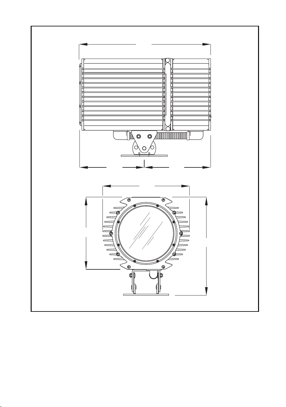
This section briefly describes how to anchor the Exterior 600 Compact. The
Exterior 600 Compact’s base allows the fixture to be manually panned 50°
and tilted +/- 40°.

12 Installation
Warning! It is the installer’s responsibility to determine the anchoring
method.
Location and orientation
The Exterior 600 Compact may be installed outdoors, in any orientation. It
must be located at least 1 meter (39 in.) away from the surface to be
illuminated and any combustible materials. The aluminum housing reaches
temperatures up to 90° C (194° F): the fixture should not be located where it
can accidentally be touched.
When choosing a location for the fixture, consider that it has an ingress
protection rating of 65. This means that the fixture is totally dust proof and
that it is protected from water ingression to the extent that moisture from
low-pressure water jets from any direction cannot get into the product.
However, the product is not designed to withstand:
• High-pressure water jets from any direction
• Immersion in water (or any other fluid)
The Exterior 600 Compact requires free-circulating air for cooling. Do not
bury the Exterior 600 Compact or otherwise locate it in an unventilated
space.
To achieve the full tilt range, the fixture must be installed on a pedestal at
least 12 cm (4.7 in) long. To achieve the full pan range, the fixture must be
anchored with 4 fasteners that can be loosened, spaced at 90° intervals as
described below.
Fastener spacing and type
Warning! Verify that the structure can bear the weight of all installed
fixtures. Use at least one fastener in each of the 4 curved
mounting slots.
The fixture is designed to be anchored with four 10 mm (3/8 in.) bolts.
Additional bolts may be used but the pan range will be reduced. Evenly
space the bolts at 90° intervals, centered on a 170 mm (6 and 11/16 in.)
Installation 13
circle, so that one bolt passes through each curved slot in the foot of the
base.
The specific hardware will depend on the installation. Consult a qualified
engineer to determine a suitable anchoring method and to verify that the
structure can safely bear the weight of all installed devices. In general, use
high quality corrosion resistant fasteners such as zinc-plated steel, grade
8.8 or better, together with either self-locking nuts or nuts and lock-washers.
Adjusting pan and tilt
1. To adjust the pan, loosen the anchor bolts slightly so that the fixture can
turn. Manually adjust the pan position and retighten the bolts.
2. To adjust the tilt, loosen both tilt locks on either side of the base. Position
the fixture and retighten the tilt lock nuts.

14 AC power
AC power
Power configuration
This section describes connection to AC power. Your Exterior 600 Compact
is factory-wired to one of the following settings:
• 230V/50Hz
• 245V/50Hz
• 208V/60Hz
Operating at the incorrect power setting can result in poor light output,
greatly reduced lamp life, overheating and damage to the fixture. The
factory settings are printed on the serial number label. If your local AC
voltage or frequency differ from the settings for your model, then see
“Changing the power settings” on page 69.
Connection to the mains supply
The Exterior 600 Compact is equipped with a 1.8-meter (5.9 ft.) length of 3-
conductor 0.75 mm
2
(~18 AWG) electrical cable for connection to the AC
power supply. The supplied mains cable has a neoprene rubber jacket. The
cable enters the fixture through a cable gland that fits 5.5-10 mm (2-4 in.)
diameter cables.
Note: If there is a breach or cut at any point along the power cable
(for example at a connection point), and if this is exposed to
water, moisture can be drawn up the inside of the cables due to
the vacuum effect from the heat generated during operation.
When installing the product outdoors, always ensure that the
fixture is protected from water ingression from inside its power
cable by:
• Protecting the connectors on the power cables in a weatherproof
housing, or a weatherproof electrical junction box (see
manufacturer’s instructions), or
• Replacing the supplied cable with one that connects directly inside
the fixture (see“Hard wiring the fixture to the mains supply” on
page 15), or

AC power 15
• Using IP65 rated cord caps (see “Installing a cord cap on the mains
lead” on page 17).
Warning! Do not connect the Exterior 600 Compact to an electrical
dimmer system. Doing so can damage the electronics.
For protection from dangerous electric shock, the fixture must
be grounded (earthed). The AC mains supply must be fitted with
a fuse or circuit breaker and ground-fault protection.
Hard wiring the fixture to the mains supply
Prerequisites
• Use Hypalon or neoprene rubber-jacket cable. The conductor size must
be no less than 1.5 square mm (ca. 16 AWG).
• Verify that the power supply is tapped for the local AC voltage and
frequency. The factory supplied rating can be found on the fixture serial
number label.
• Verify that the feed cable is undamaged and rated for the current
requirements of all connected devices.
• if you have any doubts about proper installation, consult a qualified
electrician.
• Consult a qualified electrician if the Exterior 600 Compact is to be
connected directly to building wiring. There must be a switch in the circuit
to turn power off when the fixture is not in use or is being serviced.
Replacing the mains lead
1. Make sure the Exterior 600 Compact is isolated from AC power and is
cool.
2. Remove the 10 Allen screws from the rear cover plate.
3. Pull off the plate and seal.
16 AC power
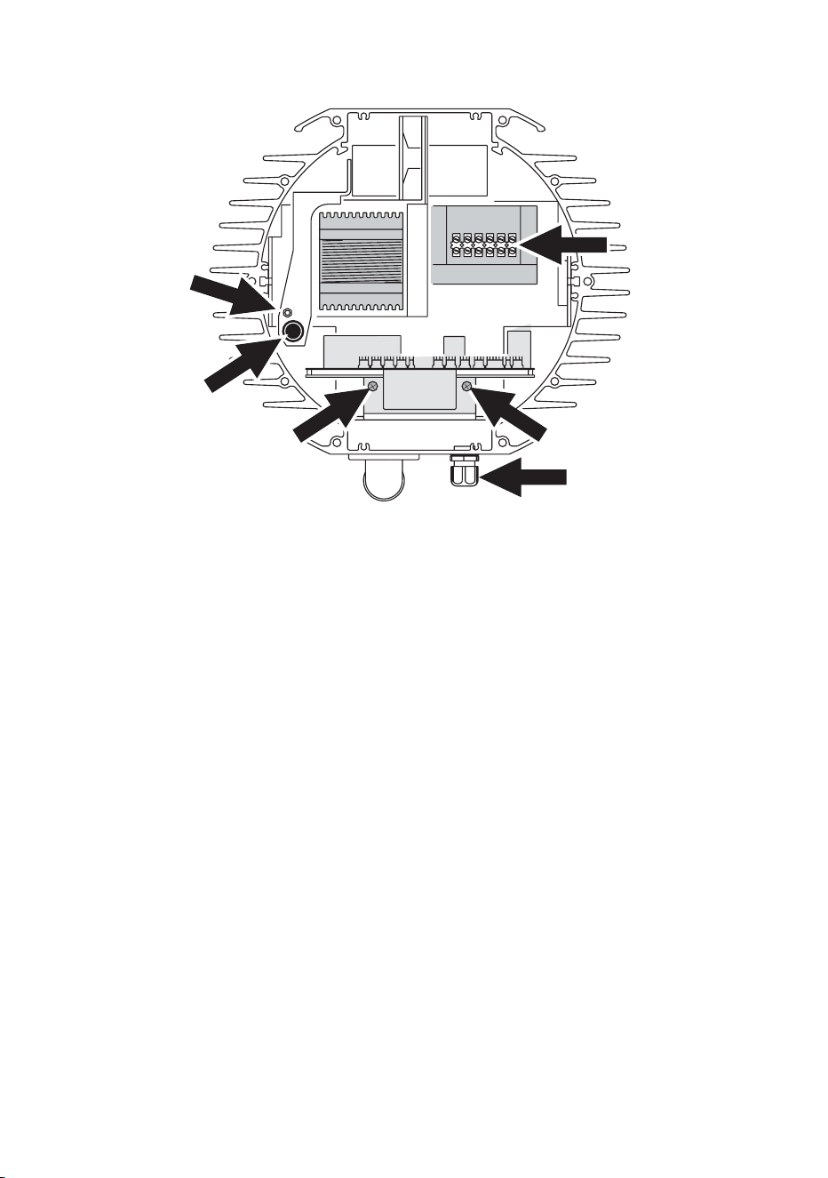
4. Remove the 2 screws from the aluminum circuit-board bracket (A) and
pull the circuit board out.
5. Unplug the power cable’s brown lead from the back of the main fuse
holder (B). The lead is connected with a spade plug and can be pulled
off.
6. Remove the green/yellow lead from the grounding bolt (C) to the left of
the ballast.
7. Disconnect the blue lead from the connection block (D) located in front
of the transformer.
8. Loosen the large outer nut on the mains lead pass-through fitting (E).
Cut cable ties as necessary and pull the mains lead out of the fixture.
9. Transfer the outer pass-through nut (E) to the new cable and then insert
the new cable through the fitting. Pull the cable into the fixture and cut to
52 cm (20 in.) from the inside of the pass-through.
10. Remove 28 cm (11 in.) of outer insulation. Lead the cable between the
fuse holder and housing (at B).
11. Install a ring terminal on the ground lead (green/yellow), place the
terminal on the grounding bolt to the left of the ballast (C), and replace
the nut.
12. Strip 6 mm (1/4 in.) of insulation from the neutral lead (blue) and screw
the lead into the neutral terminal of the connection block in front of the
transformer (D).
A A
B
C
D
E
AC power 17
13. Install a 6.3 mm (1/4 in.) insulated female spade terminal on the live lead
(brown), and plug the lead into the back of the main fuse holder (B).
14. Replace the printed circuit board (A). Bundle the wires together as
before with zip ties.
15. Verify that both nuts on the pass-through fitting are tight (E). Check the
condition of the seal for the back cover. Replace with a new one (P/N
20600020) if the seal is torn, cracked or brittle.
16. Insert the Allen screws through all holes in the cover and the seal. Place
the cover firmly against the body. Adjust the straight sides of the seal so
that they stick out a little, just enough so that you can feel the seal when
you run a finger across the joint.
17. Cross-tighten the cover bolts evenly. The correct torque for these bolts
is 2 Nm (1.5 Ft-Lbs). At this torque, the seal will be compressed by about
one-third.
The cable gland must be replaced if the outside cable diameter is larger
than 10 mm or smaller than 5.5 mm. See “Cable glands” on page 55.
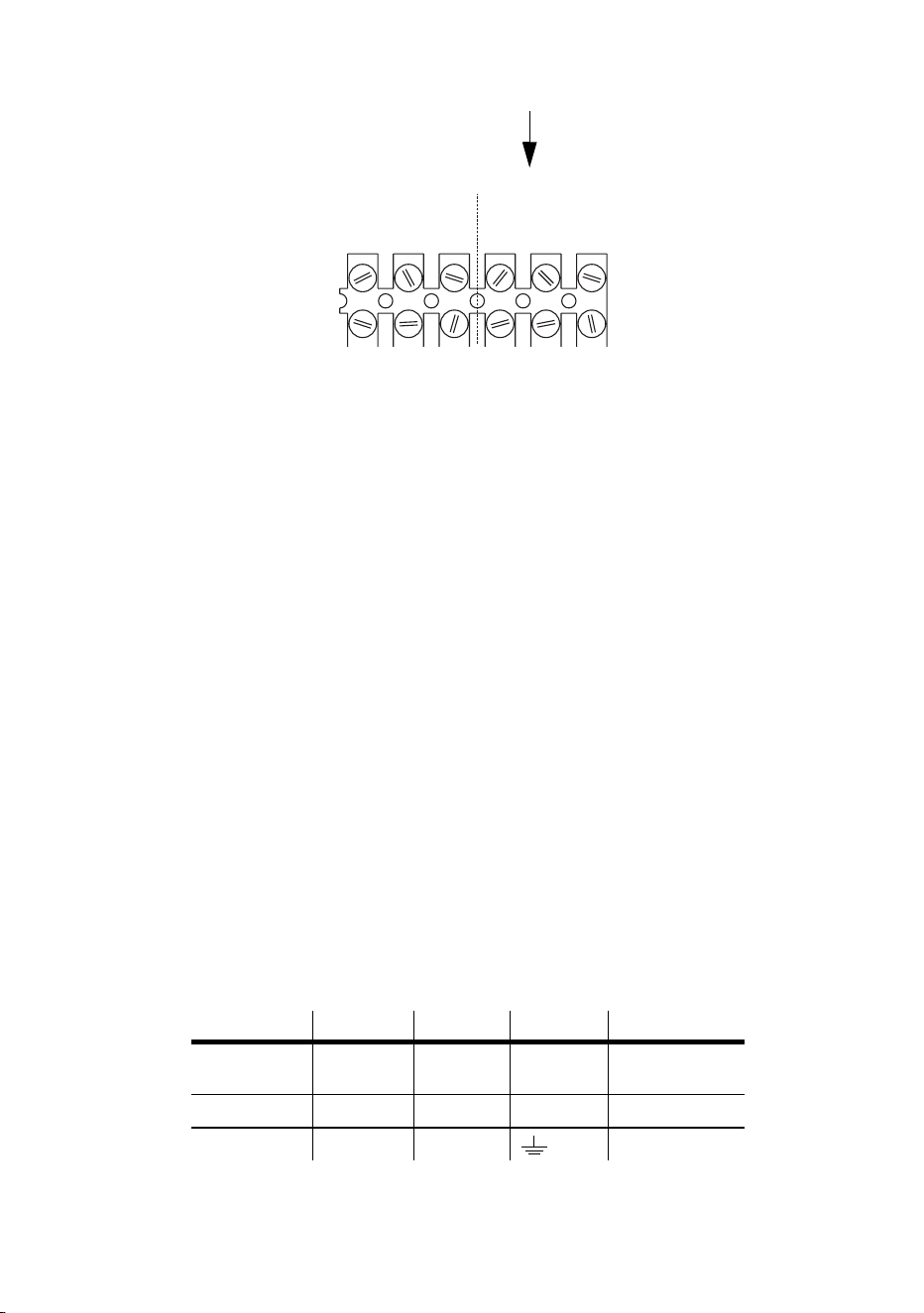
Installing a cord cap on the mains lead
A non-IP-rated cord cap may be installed on the mains lead for testing,
service, and temporary applications. For outdoor installations an IP65-rated
cord cap should be used. The following table details some commonly used
wiring configurations.
Wire (EU) Wire (US) Pin Marking Screw (US)
brown black live “L” yellow or
brass
blue white neutral “N” silver
yellow/green green ground green
SERIAL DATA LINK MAINS INPUT
MAINS INPUT
LIVENeut.Gnd.
(Brown)(Blue)(Yellow)
Gnd.HotCold
(Blue)(Red)(Green)
(Green)

18 AC power
Following the cord cap manufacturer’s instructions, connect the yellow and
green wire to ground (earth), the brown wire to live, and the blue wire to
neutral. Consult an electrician if you have any doubts about proper
installation.
Warning! For protection from dangerous electric shock, the fixture must
be grounded (earthed). The AC mains supply must be fitted with
a fuse or circuit breaker and ground-fault protection.

Data link 19
Data link
A data link is required for DMX controller operation, and for synchronized
stand-alone operation of multiple fixtures.
Cable and junctions
The Exterior 600 Compact provides a dual 1.8 meter (5.9 ft.) 24 AWG cable
with locking 3-pin male and female XLR connectors for data connection.
The male cable is the data input and the female cable is the data output.
The connectors are wired pin 1 to shield (gnd.), pin 2 to signal - (cold), and
pin 3 to signal + (hot).
Use RS-485 data cable designed for outdoor use to extend the link. RS-485
cable has low capacitance and a characteristic impedance of 85 to 150
ohms. It is electrically shielded and has at least 1 twisted-pair of conductors.
The minimum wire size is 0.2 mm2 (24 AWG) for runs up to 300 meters
(1000 ft.) and 0.322 mm2 (26 AWG) for runs up 500 meters (1640 ft.).
Warning! Fixtures produced from the middle of 2004 will be supplied with
Neutrik NC3MX-HD-B and NC3FX-HD-B weatherproof IP65-rated
XLR connectors.
Connectors on earlier models are not weatherproof, and if these
connectors are exposed to water, moisture can be drawn up the
inside of the cables due to the vacuum effect from the heat
generated during operation. When installing the product
outdoors, always ensure that the fixture is protected from water
ingression from inside its data cable by:
• Protecting the connectors on the data cable in a weatherproof
housing (or a weatherproof electrical junction box), or
• Using IP65 rated XLR cable and connectors (such as the NC 3 MX-
HD-B and NC 3 FX-HD-B produced by Neutrik).
20 Data link
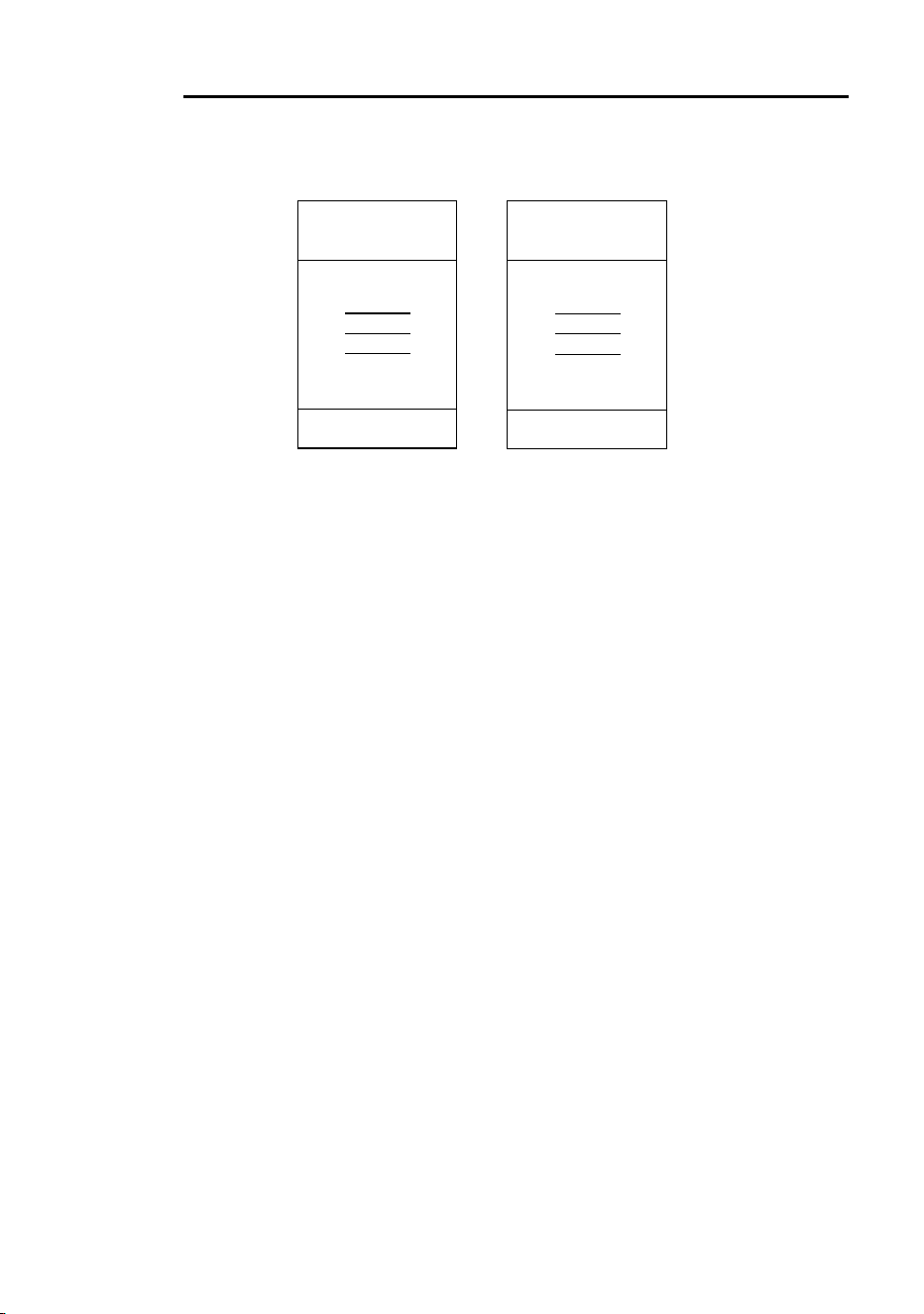
Adaptors
Adaptors may be required to connect the Exterior 600 Compact to the
controller or other 5-pin devices. Adaptor cables for indoor use are available
from Martin. The adaptor cables are wired as shown below.
Splitter/Amplifiers
A device such as the Martin 4-Channel Opto-Isolated RS-485
Splitter/Amplifier may be used to branch the data link and/or extend its
length. Do not use a “Y” connector to split the link.
Terminators
Termination of the data link is required for trouble-free communication. For
temporary installations, this can be achieved with an IP65 weatherproof
male termination plug inserted into the data output cable of the last fixture in
each chain. A termination plug is simply an XLR connector with a 120 ohm
resistor soldered across pins 2 and 3.
For permanent terminations, the link can be terminated inside the last fixture
in each chain, using a 120 ohm resistor across the hot and cold data
Adaptor
Male Female
1
2
3
4
5
1
2
3
5-pin to 3-pin
P/N 11820005
Adaptor
Male Female
1
2
3
1
2
3
4
5
3-pin to 5-pin
P/N 11820004
Data link 21
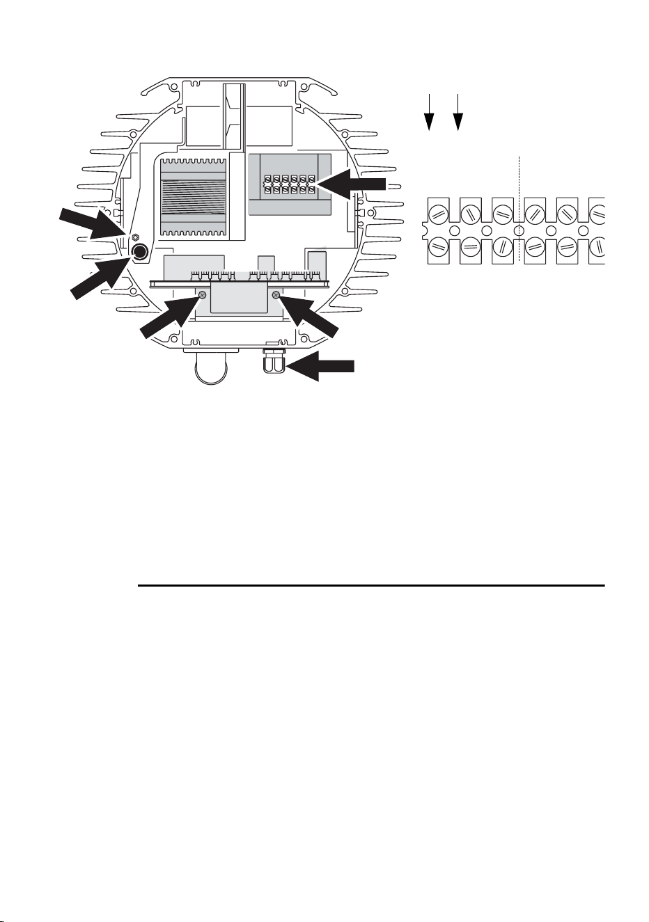
terminals on the main circuit board, or across the corresponding terminals
on the connection block (at position E).
If you terminate the data link internally then you will need to change the
supplied dual cable (with male and female XLR connectors) to a single
cable with a male connector. The process for changing the XLR cable is
very similar to that for changing the power lead (see “Hard wiring the fixture
to the mains supply” on page 15). The cable enters the fixture (at position E)
and the leads are connected to the connection block (at position D).
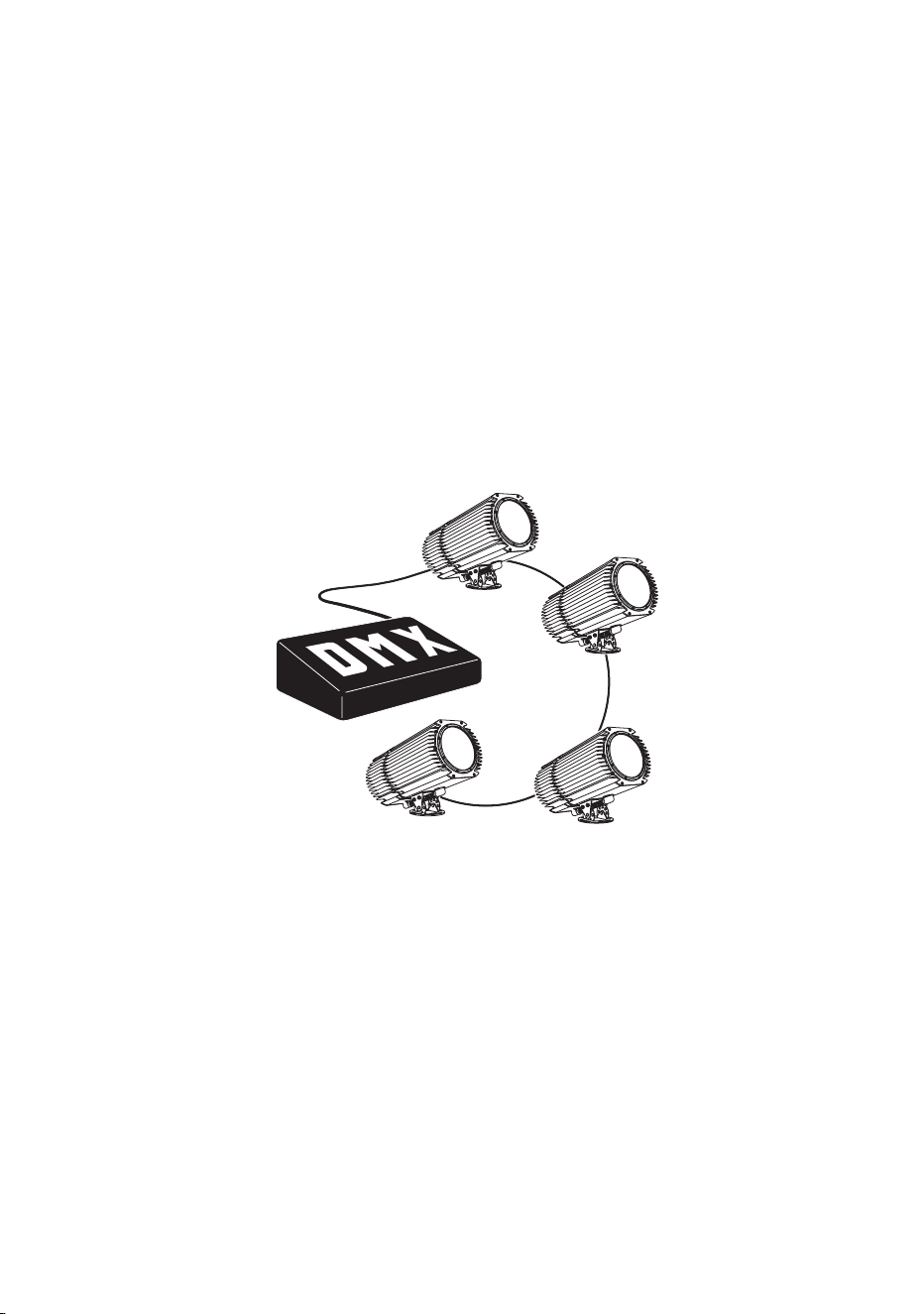
Building a data link
To build a data link:
1. Connect a data cable to the controller’s data output. A male 5-pin to
female 3-pin adaptor may be required. Lead the data cable from the
controller to the first fixture and plug it into the fixture’s male data cable.
2. Connect the output of the fixture closest to the controller to the input of
the next fixture. Continue in this manner. Up to 32 fixtures may be
connected output to input.
3. Terminate the link as described above, at the output of the last fixture in
the chain.
A A
B
C
D
E
SERIAL DATA LINK MAINS INPUT
MAINS INPUT
LIV
ELIVE
Neut.Gnd.
(Bro
w(Brown)
(Blue)
(Blue)
(Yellow)
(Yellow)
Gnd.HotCold
(Blue)
(Blue)
(Red)
(Red)
(Green)
(Green)
22 Fixture settings
Fixture settings
This section describes how to set the control address, clock, and other
fixture personalities. There are three ways to define fixture settings:
Multi-
Utility
Manager
Multi-Utility Manager (MUM) is a PC software application
supplied with a DABS1 USB-to-XLR communications
adaptor. We recommend MUM because it provides an
intuitive, easy-to-use, graphical user interface.
One limitation with MUM is that you can only connect to,
and set-up, one fixture at a time.
See “Defining fixture settings using MUM” on page 24.
Fixture settings 23
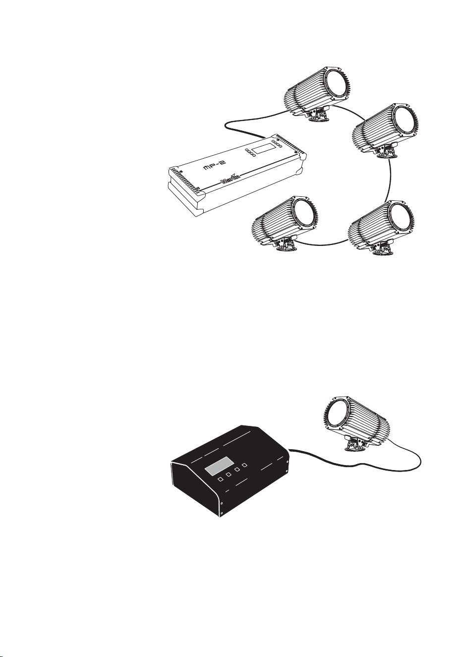
Martin
MP-2
Uploader
The MP-2 uploader can be loaded with the Exterior 600
Compact’s control software and connected to the fixture or
data link.
When working with multiple fixtures the Uploader allows
you to apply settings globally to multiple fixtures on a data
link.
The MP-2 provides a text-based interface and the fixtures
do not provide feedback to the uploader. Therefore, the
current settings of the fixture can only be “read” by
observing the behavior of the fixture.
Refer to the respective MP-2 user manual for more
information.
DMX
Address
Device
DMX Address Device (DAD) is a hardware device that can
be used to set the DMX address of one Exterior 600
Compact at a time.
If you need to set other fixture settings - such as the
internal clock - then you will also need to use an MP-2
Uploader or MUM to completely set-up the fixture.
Refer to the DMX Address Device user manual for more
information.
24 Fixture settings
Defining fixture settings using MUM
Using the MUM you can connect to and set up one fixture at a time. Refer to
the MUM user manual for instructions on installing and starting the MUM
application.
Support for the MUM application is available from Version 2 of the Exterior
600 Compact software.
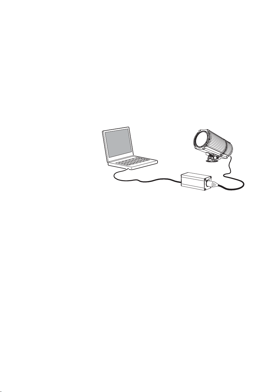
To get started:
1. Connect a DABS1 adaptor to your PC.
2. Connect the DABS1 adaptor to your Exterior 600 Compact.
3. Power on the Exterior 600 Compact and start the MUM application. The
application will automatically detect an Exterior 600 Compact if it is
powered-on and connected to your computer via a DABS1 adaptor. It
will also retrieve the current settings on the fixture and display them.
Clock
The Exterior 600 Compact has a battery operated 24-hour clock that can
start and stop stand-alone operation.
To set the clock:
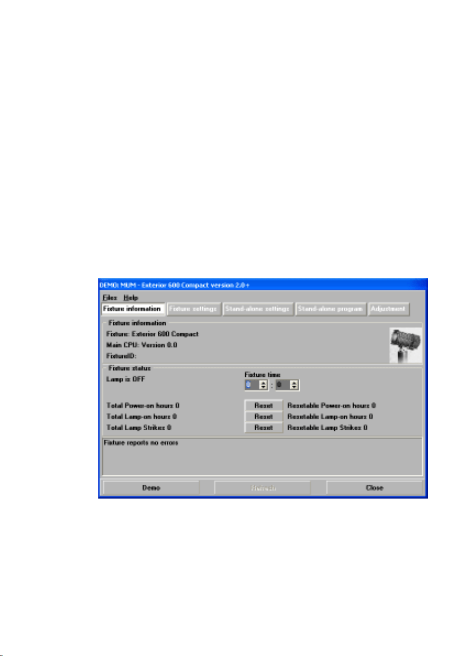
1. Using MUM, click on the Fixture information button:
2. Using the two Fixture time spin buttons set the fixture to the current
time (expressed in the 24-hour clock in hours and minutes). The time will
be updated in the fixture in real-time.
PC
Exterior 600 Compact
DABS1
Fixture settings 25
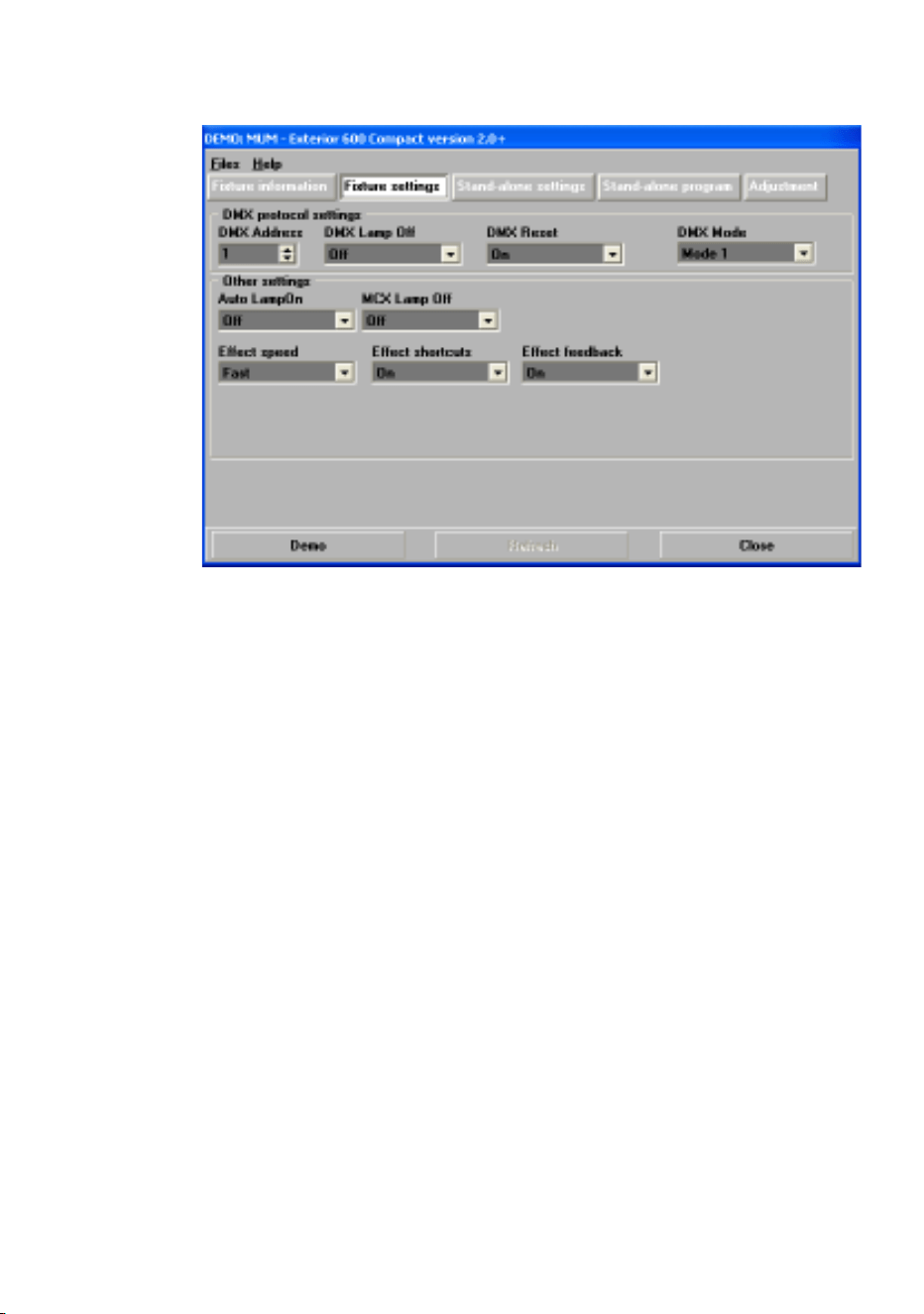
Fixture settings
To set the additional fixture settings, click on the Fixture settings button:
In most situations the default settings will appropriate.
DMX Protocol settings
These are described in “Preparing a fixture for DMX control” on page 46.
Refer to this section if you will be operating the Exterior 600 Compact with a
DMX control device.
Automatic lamp on
When the Automatic Lamp On personality is on, the fixture turns on the
lamp within 90 seconds of power on. When set to off (the default setting), a
lamp-on command is required to turn on the lamp.
MC-X lamp off
By choosing the option MCX Preset 7 Key from the MCX Lamp off field
you enable button 7 on an MC-X controller to be used to control the lamp off
function.
Effect speed
Effects are performed quickly (Fast=default) or slowly (Safe).

26 Fixture settings
Effect shortcuts
This determines whether the wheel takes the shortest path to the next
position or turns in one direction only. This is on by default.
Effect feedback
Effect feedback is a real-time position correction system that automatically
corrects the position of the effect wheels. This is on by default.

General operation 27
General operation
When the Exterior 600 Compact is connected to power it will reset.
Lamp operation
Avoid turning on several lamps at once.
To optimize lamp life, always allow the lamp to warm up fully before turning
it off.
For optimum lamp life, turn off lamp power whenever illumination is not
required for extended periods of an hour or more. Fixture power may remain
on when not in use.
After being turned off, the lamp must cool for at least 8 minutes before it can
be turned back on. “Lamp on” commands sent within 8 minutes of a “lamp
off” command are stored and then attempted again after the time has
elapsed.
Cold weather operation
When the temperature is expected to fall below freezing, leave the fixture
powered on when not in use to keep the electronics warm. The lamp,
however, may be switched off.
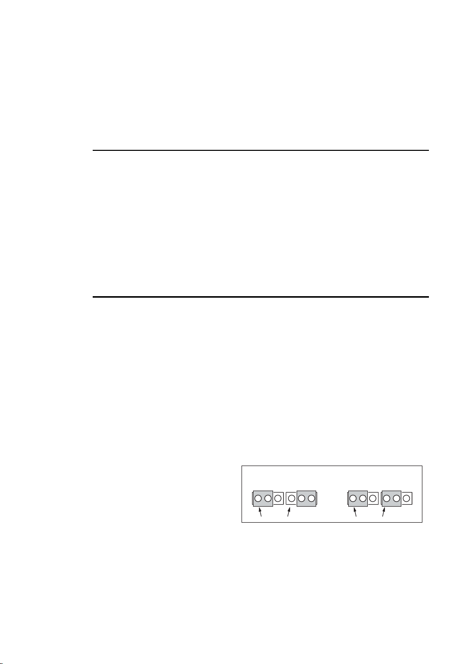
The LEDs and fixture operating
status
Two LEDs on the rear panel display the
fixture status. Normal operation is indicated
by two green LEDs. See Table 1 for other
status messages.
LED 1 LED 2 SENSOR

28 General operation
The LEDs flash off for a brief instant at regular intervals to prevent false
readings when the light sensor samples the light level.
The three-digit version number (major.minor.build) of the installed firmware
is displayed by the LEDs on power up; the number of:
• Red flashes in LED 1 indicate the major number, followed by,
• Green flashes in LED 2 indicate the minor number, followed by,
• Red flashes in LED 2 indicate the build number (only used for beta
releases)
For example, if the firmware version is 1.3.0, LED 1 flashes red once and
LED 2 flashes green three times.
Fixture control methods
The Exterior 600 Compact can be controlled:
• With DMX signals from a DMX control device such as a DMX recorder or
DMX controller. This is described in “Section 3. DMX control” on page 45.
• Using stand-alone programming. There are two ways of programming
and storing a show in the fixture itself:
a. From a personal computer, using the Martin MUM software
application, or
b. Via an MP-2 Uploader
Stand-Alone programming is described in “Section 2. Stand-Alone
operation” on page 31.
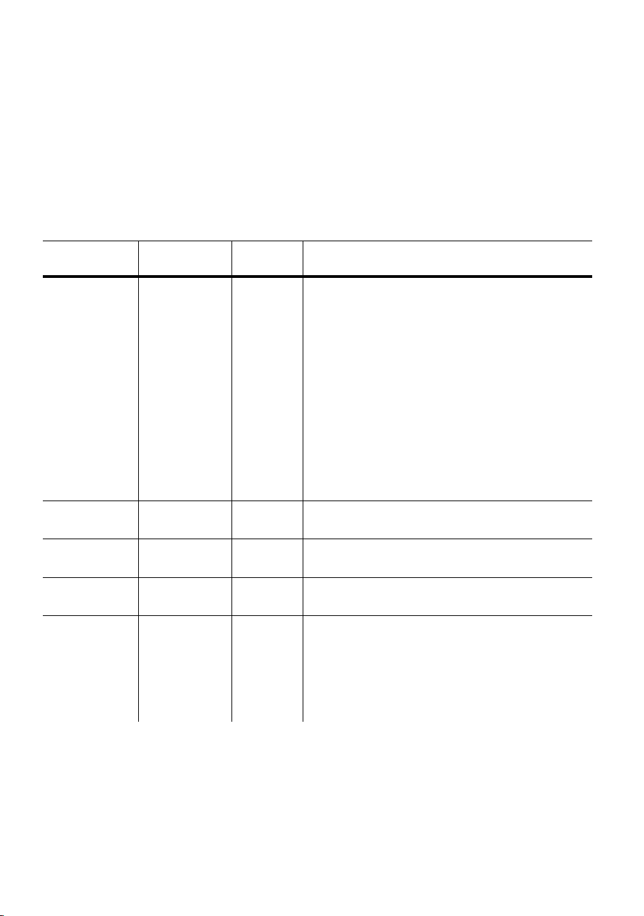
Appearance Message, LED 1 Message, LED 2
Steady green Effects OK Data OK.
Steady red - Invalid data/no data
Steady yellow Waiting for upload, or
upload in progress
Waiting for upload, or
upload in progress
Flashing yellow Reset in progress Reset in progress
Flashing red & green Contact a service
technician
Off - No data detected
Table 1: LED status messages
General operation 29
Color matching Exterior 200s and
Exterior 600 Compacts
If you are running Exterior 200 and Exterior 600 Compact fixtures together
in the same installation, colors will not match perfectly when the same CMY
values are used, because these fixture use different lamps.
Generally speaking, the relatively:
• Higher-powered lamps used in the Exterior 600 Compact result in deeper
colors in the cold colors of the spectrum.
• Lower-powered lamp used in the Exterior 200 will give deeper colors in the
warm colors of the spectrum.
The following table gives some approximate values for color matching:
Color
Exterior 600 Compact
(with MSD 575 lamp)
Exterior 200
(with CDM lamp)
White Magenta 25
Yellow 44
Open
White Open Cyan 74
Yellow Yellow 241
Magenta 16
Full yellow
Magenta Magenta 100
Yellow 68
Full magenta
Cyan Full cyan
Magenta 25
Yellow 44
Full cyan
Red Full magenta
Full yellow
Full yellow
Magenta 215
Green Cyan 241
Yellow 241
Full cyan
Full yellow
Blue Full cyan
Full magenta
Cyan 255
Magenta 191

30 General operation


32 Stand-Alone programming overview
Stand-Alone
programming
overview
Stand-alone is a mode where the fixture executes color changes at set
intervals and speeds, at pre-defined periods during the day, and/or when
the light level falls below a defined level. The term stand-alone is used to
mean that the Exterior 600 Compact is not connected to a control device,
but is pre-programmed with a series of up to 20 scenes that play
continuously in a loop. The term ‘stand-alone operation’ can be applied to a
single fixture, or to multiple fixtures operating synchronously.
An Exterior 600 Compact running a stand-alone show can perform
synchronized scene changes (triggered by a master fixture) with up to 31
other Martin fixtures of the following types:
• Exterior 200
• Exterior 600 Compact
• Exterior 600
• FiberSource CMY150
• Imager series
• Alien 02 series
•MiniMAC Maestro
These fixtures all have their own shows individually programmed, but have
scenes synchronously triggered by a one fixture. Synchronous operation of
multiple fixtures requires that they be connected on a data link.
Stand-Alone programming overview 33
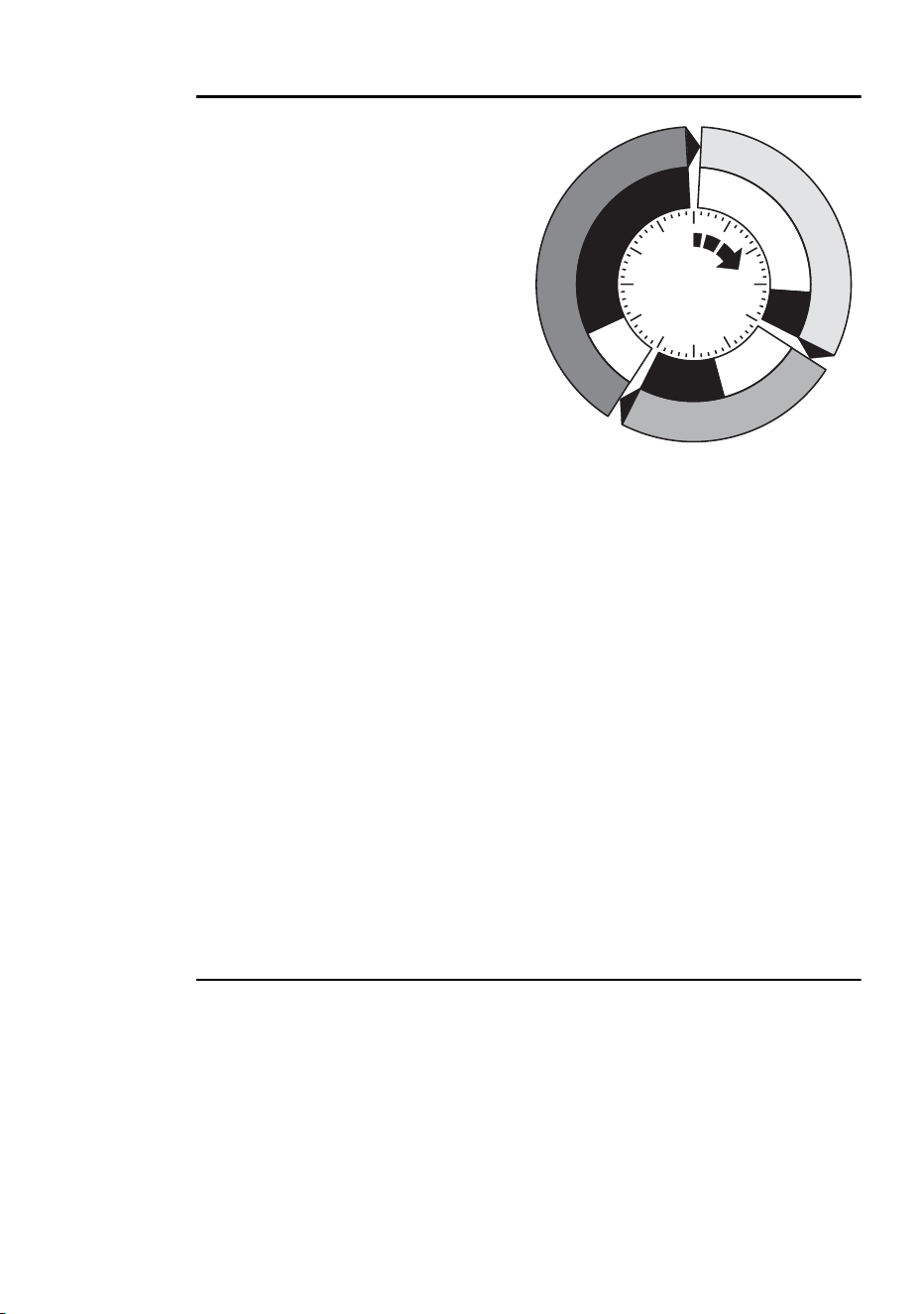
About scene timing
Each scene has a dynamic part -
the fade - during which effects
move to the scene’s programmed
positions, and a static part - the
wait - where effects do not change.
The duration of the fade and wait is
programmed individually for each
scene. The fade time may be 0 -
120 seconds; the wait time may be
1 second to 12 hours. The total
time it takes a scene to execute is
the sum of the fade and wait times.
When operating multiple fixtures synchronously, the wait time is determined
by the fixture that issues scene change commands. It does this when it
reaches the end of each scene wait time. Every other fixture fades and waits
at its own rate and then remains in the “wait state” until it receives a start
scene xx command. When programming in synchronous triggering
situations, keep in mind that in order to keep things as simple as possible
there are two rules of thumb that will make life much easier; try to ensure
that:
1. Every fixture has the same number of scenes.
2. Respective scene times are a few seconds longer on the fixture that
issues triggering commands.
The rules used in the algorithm are detailed in “Synchronous triggering
during Stand-Alone operation” on page 43.
Synchronizing scene changes for
multiple Exterior 600 Compacts
In situations where you are running multiple Exterior 600 Compacts on a
data link it is possible to synchronize scene changes.
It is important to note that each individual fixture must be programmed with
a show and that the only commands that are passed are scene change
commands. No data about the look of the scene is passed between fixtures.
Fade
Fade
S
c
e
n
e
1
S
c
e
n
e
1
S
c
e
n
e
3
S
c
e
n
e
3
S
c
e
n
e
2
S
c
e
n
e
2
Wait
Wait
Wait
Fade

34 Stand-Alone programming overview
Programming methods
The Exterior 600 Compact provides two stand-alone programming methods;
using the:
• Martin MUM application from a personal computer (recommend because
it provides an intuitive, easy-to-use, graphical user interface), or an
• MP-2 Upload device. See the MP-2 user manual for further information.
If you are programming a group of fixtures to perform the same scenes with
synchronized triggering then we recommend that you either:
• Use an MP-2 Uploader to program the same show on all fixtures on the
network simultaneously (and then you can assign their individual DMX
address afterwards), or
• Use MUM to program a single fixture, download and save the fixture
settings to a file on your PC, and then upload the stand-alone program
and fixture settings to each subsequent fixture that you connect to.
Programming from a PC using MUM 35
Programming from a
PC using MUM
The programming of scenes, and setting up of master/slave relationships,
can be performed from a personal computer using the MUM application.
The computer is connected to a fixture via a DABS1 USB-to-XLR adaptor,
used to program the stand-alone settings for that fixture, and then removed.
Once a fixture is subsequently switched on it can automatically run the
scenes in its program in a loop, according to the triggering criteria you have
specified (time of day, and/or light level).
If you are not familiar with the use of MUM, then it is recommend that you
familiarize yourself with it by reading the MUM user manual.
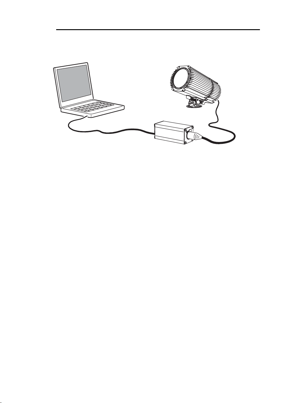
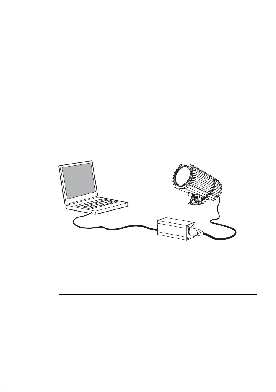
Getting started
To get started:
1. Connect a DABS1 adaptor to your PC.
2. Connect the DABS1 adaptor to your Exterior 600 Compact.
3. Power on the Exterior 600 Compact and start the MUM application. The
application will automatically detect an Exterior 600 Compact if it is
powered-on and connected to your computer via a DABS1 adaptor. It
will also retrieve the current settings on the fixture and display them.
PC
DABS1
Exterior 600 Compact
36 Programming from a PC using MUM
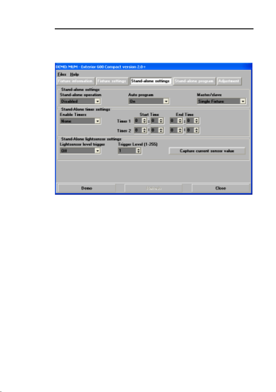
Stand-Alone Settings
The fixture needs to be configured to know if and when to activate a stand-
alone program:
Click Stand-alone settings to display the following window.
The following options are available:
Stand-alone
operation
Activates or deactivates stand-alone operation.
Auto program Enables the stand-alone program to start
automatically when the fixture is powered-on. If a
DMX signal is removed from the fixture and this
setting is enabled, the fixture will resume stand-alone
operation.
Master/slave Specifies if the fixture is a single, “master”
(triggering), or “slave” (receiving trigger signals)
fixture.
No more than one fixture may be the master. Any
fixture on the link, however, regardless of its position,
may be the master. All other fixtures must be set as
slave fixtures.
Stand-alone
timer settings
See “Setting a timer trigger” on page 37.
Stand-alone
light sensor
settings
“Setting a light-level trigger” on page 37.

Programming from a PC using MUM 37
Synchronizing scene changes for multiple fixtures
In situations where you are running multiple fixtures on a data link it is
possible to synchronize scene changes (for fixtures that support this
functionality - see “Stand-Alone programming overview” on page 32). Read
this section if this applies in your case.
One controlling fixture triggers simultaneous program start and scene
changes in the other fixtures. Each fixture stores its own program, and the
controlling fixture triggers simultaneous program start and scene changes,
in a cycle, based on its own program.
Each fixture will run its program repeatedly, changing scene when prompted
to by the controlling fixture, or until the controlling fixture finishes its own
program and signals that all fixtures should start from the first scene once
again.
It is important to note that each individual fixture must be programmed with
a show and that the only commands that are passed are scene change
commands. No data about the look of the scene is passed between fixtures.
Automatically triggering stand-alone operation
Stand-alone operation can be set for one or two periods during a 24 hour
period, or for a light level.
Setting a light-level trigger
The option Light level sensor trigger must be set to On.
Stand-alone operation can be set for a specific light level using the Trigger
level spin button, or captured using the built-in light sensor (press Capture
current sensor value to do this). If the light levels fall below the specified
level then operation starts.
If both the timer and the light-level sensor are used, operation starts
whenever it is darker than the light-level setting, and within the times set.
To avoid false triggering by sudden light changes, for example from
automobile headlights, the light level must remain above or below the trigger
threshold for 5 minutes.
Setting a timer trigger
Stand-alone operation can be set for one, or two, periods, during a 24 hour
period, using the built-in clock.
If both the timer and the light-level sensor are used, operation starts
whenever it is darker than the light-level setting, and within the times set.
38 Programming from a PC using MUM
The first thing to do is to set the correct time. See “Clock” on page 24.
You can set timer operation for a single period, or for two periods, for
example, one period in the morning, and one period in the evening.
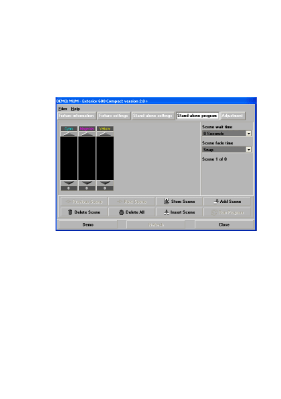
Programming effects in scenes
The programming of effects is performed using the Stand-Alone program
controls:
The following options are available:
When operating multiple fixtures in synchronized-triggering mode, the wait
time in “slave” fixtures is disregarded, and is determined by the triggering, or
“master” fixture. Each fixture fades at its own rate and then waits for the
master to signal a scene, or program, start before continuing.
Cyan
Magenta
Yellow
CMY color mixing. The CMY color mixing system is
based on graduated cyan, magenta, and yellow color
filters. A continuous range of mixed colors may be
achieved by varying the amount of each filter from 0 to
100%. Note that mixing 3 colors results in a loss of light -
the light is blacked out when all 3 colors are fully applied.
For maximum brightness, mix only 2 colors at a time.
Scene fade
time
The fade time, anything from 0 to 120 seconds, is the
time it takes to change from one color to another.
Scene wait
time
This is the duration a color is applied. A wait time can be
from 1 second to 12 hours.

Programming from a PC using MUM 39
When programming a triggering (“master”) fixture, keep in mind that its total
scene times should be equal to or longer than the fade times of the other
fixtures. You will get unpredictable results if, for example, a scene is
programmed in the master to last 10 seconds and in other fixtures to fade
for 15 seconds.
Scene management
Once you have specified a mix of effects, you can store the scene using the
options available under the Program menu:
When the program is run, scenes execute in a continuous, ascending loop.
Note that, if a “slave” fixture has:
• Fewer scenes than the master fixture, it will run these in a cycle
continuously, until the master fixture signals that the program should start
from the beginning again.
• More scenes than the master fixture, then the additional scenes will never
run, because the program will reset to the first scene when the master starts
its program from the beginning.
Programming the same stand-alone
show on multiple fixtures
Although you can only connect to and program a single fixture at a time
using the MUM, you can use it to program a single fixture, download and
save the fixture settings to a file on your PC, and then upload the stand-
Store scene Save settings in the current scene.
Add scene Save settings in a new scene at the end of the
current sequence of scenes.
Insert scene Save settings in a new scene before the current
scene, which moves up a number. Tip: Think of the
Add and Insert commands as Save commands, to be
used as the last step after programming all effects.
Delete scene Remove the current scene from memory. Scenes
above the deleted scene move down a number.
Next scene Step to the next scene.
Previous
scene
Step to the previous scene.
Delete all Remove all scenes from the fixture memory.
Run program Run the scenes in the current program.

40 Programming from a PC using MUM
alone program and fixture settings to each subsequent fixture that you
connect to. This is useful if you have a group of fixtures of the same type
that will run the same stand-alone show.

Stand-Alone show playback 41
Stand-Alone show
playback
Starting show playback
automatically at fixture power-on
Execution of the pre-programmed scenes in a loop will automatically
resume when the fixture is powered-on if stand-alone is enabled (see
“Stand-Alone Settings” on page 36) and the automatic lamp-on function is
enabled (see “Fixture settings” on page 25).
Scene execution using the optional
MC-X
The MC-X is an optional remote control unit that is available from Martin.
Once the remote controller is connected, 7 scenes can be conveniently
called up on the MC-X's buttons.
Enabling MC-X control
Using an MP-2
For each fixture:
1. Disable stand-alone operation on each fixture, select SA / run / OFF
and press [enter]. Press [menu] to exit the SA menu.
2. Using the
Per / nnO menu it is possible to set button 7 on the MC-
X to control the lamp off function. See “Specifications” on page 77.
Using MUM
For each fixture:
1. Disable stand-alone operation. See “Stand-Alone Settings” on page 36,
under the chapter “Programming from a PC using MUM”.

42 Stand-Alone show playback
2. Enable lamp-on from the MC-X. See “MC-X lamp off” on page 25 in the
section “Defining fixture settings using MUM”.
Connecting and using the MC-X Controller
1. Connect the MC-X controller to the Exterior 600 Compact’s data
network. If multiple Exterior 600 Compacts are connected, plug the
controller into the first fixture in the link.
2. To trigger scenes 00-06, press the numbered preset buttons on the MC-
X.
3. To have each fixture run its own routine, press [Auto].
DMX controller override during
stand-alone show playback
If an Exterior 600 Compact is connected to a DMX controller and receives
DMX signals during show playback, the Stand-Alone show will stop running
and the fixture will respond to the DMX controller. DMX signals always have
priority over the running of a Stand-Alone show.

Synchronous triggering during Stand-Alone operation 43
Synchronous
triggering during
Stand-Alone
operation
Note This chapter details the rules that are used in Stand-Alone
synchronous triggering. It is not necessary to read this chapter
unless you require help with problem diagnosis or unless you
otherwise need a detailed understanding of the algorithm used
for synchronous triggering.
The rules are as follows:
1. Every fixture can have up to 20 on-board scenes with individual fade and
wait times.
2. Scenes are numbered from 0 to 19.
3. A scene contains a fade-section, followed by a wait-section.
4. When running "synchronous triggering" one Exterior 600 Compact
issues commands to the other Exterior 600 Compacts to "go to scene
xx", where xx is the scene number that the master will execute next.
5. If a slave has fewer scenes than the master, it will derive which scene to
go to by dividing the number of the scene it has been commanded to go
to (scene 5, for example) by the total number of scenes that the slave
fixture has (4, for example) in whole numbers (no decimal places). In this
example 5 divided by 4 results in 1, with 1 remainder. This remainder will
be the number of the scene that the slave fixture starts - scene 1.
Generally though, when a Slave fixture reaches its own last scene
before the Master fixture, a "go to scene x" message will result in the first
scene being played.
44 Synchronous triggering during Stand-Alone operation
6. If a slave has more scenes than the master calls, the last scenes in the
slave will never be executed, as is the case with scene S4 in the
following example.
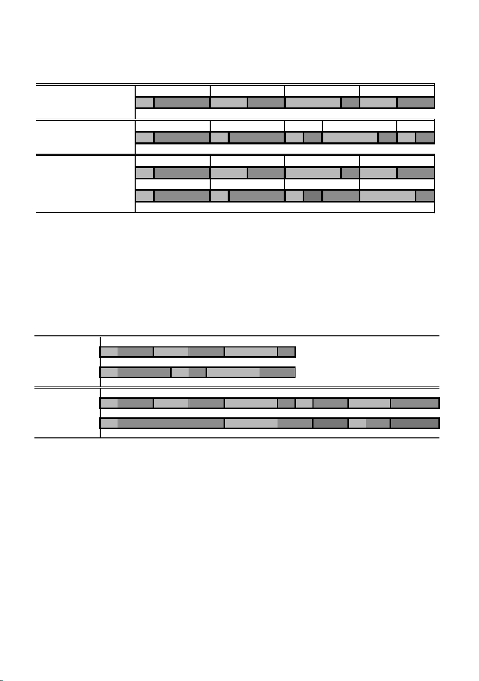
7. A slave fixture will not listen for the next message from the master fixture
before it has finished its current scene. This may result in a slave
skipping a scene if the slave has a longer scene time than the master.
Note that in the following example the scenes in the Slave run out of
their programmed sequence because scenes 0 and 2 on the Slave are
longer than the corresponding scenes on the Master.
F=fade, W=wait Timeline =>
M0 M1 M2 M3
Programmed in Master F W F W F W F W
S0 S1 S2 S3 S4
Programmed in Slave F W F W F W F W F W
Result M0 M1 M2 M3
FW FWF WFW
S0 S1 S2 S3
FW FW FW ----F W
M=master, S=slave
F=fade, W=wait Time >
Programmed M0 M1 M2
Master F W F W F W
S0 S1 S2
Slave F W F W F W
Result M0 M1 M2 M0 M1
Master F W F W F W F W F W
S0 S2 S1
Slave F W F W .. .. FW .. ..


46 Preparing a fixture for DMX control
Preparing a fixture
for DMX control
There are a range of DMX specific settings that you need to set. These are
described in this chapter. You can use a personal computer (via the MUM
application), an MP-2 or a DAD to prepare your Exterior 600 Compact. We
recommend using the MUM because it has a graphical user interface that is
easy to use (see the following illustration).
Follow the instructions in “Fixture settings” on page 22 to choose and
connect a setting device and then refer to this chapter for information about
DMX specific settings.
DMX address
The DMX address, also known as the control address, or start channel, is
the first channel used to receive instructions from the controller. Each fixture
needs its own control address set, and uses this address and subsequent

Preparing a fixture for DMX control 47
control channels to receive instructions from a controller. The Exterior 600
Compact uses four (mode 1) or five (mode 2) channels of control data.
When operating in mode 1, the fixture reads the data on the start channel
and the next four channels. If the control address is set to 100, the fixture
uses channels 100, 101, 102, and 103. Channel 104 would be the control
address for the next fixture.
If two or more fixtures are set up with the same address, they will receive
the same instructions and should behave identically. Setting up identical
fixtures with the same address is a good tool for troubleshooting
unexpected behavior and an easy way to achieve synchronized action.
To set the DMX address use the DMX Address spin button. The fixture
address is updated in real time.
DMX lamp off option
When the DMX Lamp-off personality is on (the default setting), lamp power
can be turned off from the controller by setting channel 1 to a decimal value
from 248 to 255. When set to off, the lamp-off command executes only if
channels 2, 3, and 4 are set to values from 230 to 232.
DMX reset option
When the DMX Reset personality is on (the default setting), the fixture can
be reset from the controller by setting channel 1 to a decimal value from 208
to 217. When set to off, the reset command executes only if channels 3, 4,
and 5 are set to values from 230 to 232.
DMX mode
The Exterior 600 Compact has two DMX modes of operation:
The speed at which effects fade, that is, move from one position to another,
can be controlled in two ways known as tracking control and vector control:
•With tracking control, fades are programmed using the controller’s fade
time. The controller divides the fade into small pieces that the fixture
Mode 1 Use 4 DMX channels and provides tracking
control of the fixture.
Mode 2 Uses 5 DMX channels and provides both
tracking and vector control. (Recommended)

48 Preparing a fixture for DMX control
“tracks.” The Exterior 600 Compact has a digital filter algorithm that
averages several updates to ensure smooth movement.
• Vector control provides a way to program fades on controllers without
programmable fade times or cross-faders. With vector control, instead of
breaking up the movement into many small positions, the controller
sends one position value along with a speed value that is programmed
on a separate channel. Vector control may provide smoother fades than
tracking control with some controllers, particularly on very slow fades.
Using DMX mode 2 you are able to switch between tracking and vector
control, but you cannot use both at the same time.
DMX controller operation 49
DMX controller
operation
The Exterior 600 Compact may be programmed and operated with any
lighting controller that is compatible with the USITT DMX standard. This
section describes how to operate the fixture with a controller.
Refer to “Data link” on page 19 for connection requirements and the “DMX
protocol” on page 52 for specific control values.
This chapter contains the following sections:
• “Effect operation” on page 50
• “Lamp” on page 51
• “Color” on page 51
Important: If an Exterior 600 Compact is connected to a DMX controller and
receives DMX signals during stand-alone show playback, the
stand-alone show will stop running and the fixture will respond
to the DMX controller. DMX signals always have priority over
the running of a stand-alone show.
DMX control device

50 DMX controller operation
Effect operation
The effects reset to their “home” position when the Exterior 600 Compact is
powered on. The Exterior 600 Compact can also be reset from the controller
on channel 1. If the DMX Reset personality is off (see “DMX reset option” on
page 47), the reset command only works if each of the CMY channels is set
to a DMX value from 230 to 232.
Speed
The speed at which effects fade, that is, move from one position to another,
can be controlled in two ways known as tracking control and vector control.
These are explained in “DMX mode” on page 47.
Using DMX mode 2 you are able to switch between tracking and vector
control:
• Tracking control is enabled by setting channel 9, the speed channel, to a
decimal value from 0 to 2. Fades are then programmed using the
controller’s cross-faders. The Exterior 600 Compact has a digital filter
algorithm that averages several updates to ensure smooth movement.
• A vector speed is programmed by setting the speed channel to a decimal
value from 3 (fastest) to 245 (slowest). The speed setting applies to
dimmer and color fades. When using vector control, the controller cross-
fade time, if available, must be 0.
Feedback
An on-the-fly position correction system automatically corrects the position
of the effect wheels. This feature can be disabled by turning effects
feedback off (see “Effect feedback” on page 26), but this is not
recommended.
Shortcuts
The shortcuts setting (see “Fixture settings” on page 25) determines
whether the effect wheels take the shortest path between two positions,
crossing the open position if necessary, or always avoid the open position.
The setting may be overridden on the speed channel (only available in DMX
mode 2 - see “DMX mode” on page 47).

DMX controller operation 51
Lamp
Lamp on
With the default setting, the lamp remains off until a “lamp on” command is
sent from the controller. To have the lamp strike automatically within 90
seconds of powering on, activate the Automatic Lamp On personality (see
“Fixture settings” on page 22).
A large peak of electric current is drawn for an instant when striking a
discharge lamp. Striking many lamps at once may cause a voltage drop
large enough to prevent lamps from striking and/or trip circuit breakers.
When striking multiple lamps, program a sequence that strikes lamps one at
a time at 5 second intervals. If Automatic Lamp On is enabled, there is a
delay of up to 90 seconds that is determined by the fixture address.
Lamp off
The lamp can be turned off from the controller by sending a “lamp off”
command on channel 1. If the DMX Lamp Off personality is off (see “DMX
lamp off option” on page 47), the command only works if each of the CMY
channels (3, 4, and 5) is set to a DMX value from 230 to 232.
After being turned off, the lamp must cool for at least 8 minutes before it can
be turned back on. “Lamp on” commands sent within 8 minutes of a “lamp
off” command are stored and then executed after the time has elapsed.
Color
CMY subtractive color mixing
The CMY color mixing system is based on graduated cyan, magenta, and
yellow color filters. A continuous range of mixed colors may be achieved by
varying the amount of each filter from 0 to 100%. Note that mixing 3 colors
results in a loss of light - the light is blacked out when all 3 colors are fully
applied. For maximum brightness, mix only 2 colors at a time.
Random color mixing
Random color mixing with the CMY system at slow, medium, and fast
speeds is available on channel 1. These random commands take
precedence over values set on the cyan, magenta, and yellow channels.
52 DMX protocol
DMX protocol
Start code = 0
DMX
channel
Value Percent Function
1
* If the
command is
disabled, set
channels 2,
3, and 4
(CMY) from
230 to 232.
0 - 19
20 - 49
50 - 127
128 - 147
148 - 167
168 - 187
188 - 207
208 - 217
218 - 227
228 - 237
238 - 247
248 - 255
0 - 7
8 - 19
20 - 44
44 - 58
58 - 65
66 - 73
74 - 81
82 - 85
85 - 89
89 - 93
93 - 97
97 - 100
Light, Reset, Lamp On/Off
Blackout (CMY full)
Light (CMY as programmed)
Open white (CMY off)
Random color, fast
Random color, medium
Random color, slow
Open white (CMY off)
Reset fixture*
Open white (CMY off)
Lamp power on
Open white (CMY off)
Lamp power off* Note: T Š 5 seconds
2 0-255 0 - 100
Cyan
White ! Cyan
3 0-255 0 - 100
Magenta
White ! Magenta
4 0-255 0 - 100
Yellow
White ! Yellow
5
(Mode 2
only)
0 - 2
3 - 245
246 - 248
249 - 251
252 - 255
0 - 1
1 - 96
96 - 97
98 - 98
99 - 100
Speed
Tracking
Fast ! slow
Tracking, no shortcuts (override SCUT ON)
Tracking, shortcuts on (override SCUT OFF)
CMY fast (no blackout)

DMX protocol 53
S
ECTION
4. S
ERVICE
AND
TROUBLESHOOTING
This section contains the following chapters:
• “Seal maintenance” on page 54
• “Cleaning” on page 56
• “Firmware updates” on page 57
• “Adjusting field angle” on page 60
• “Lamp maintenance” on page 62
• “Maintaining the electrical system” on page 67
• “Troubleshooting” on page 72

54 Seal maintenance
Seal maintenance
The Exterior 600 Compact has an IP rating of 65: it is protected against dust
and can withstand low pressure water jets. To maintain protection against
dust and water:
• Replace any seal that becomes brittle or shows visible signs of wear.
• Verify that seals are flush with, or protrude slightly above, the surface of
the aluminum covers.
• Verify that cable pass-through fittings are tightened both to the casing
and the cable.
• Tighten the end plates and the lamp access plate to a torque of 2 Nm
(1.5 Ft-Lbs). At this torque, the seals will be compressed by about one-
third.
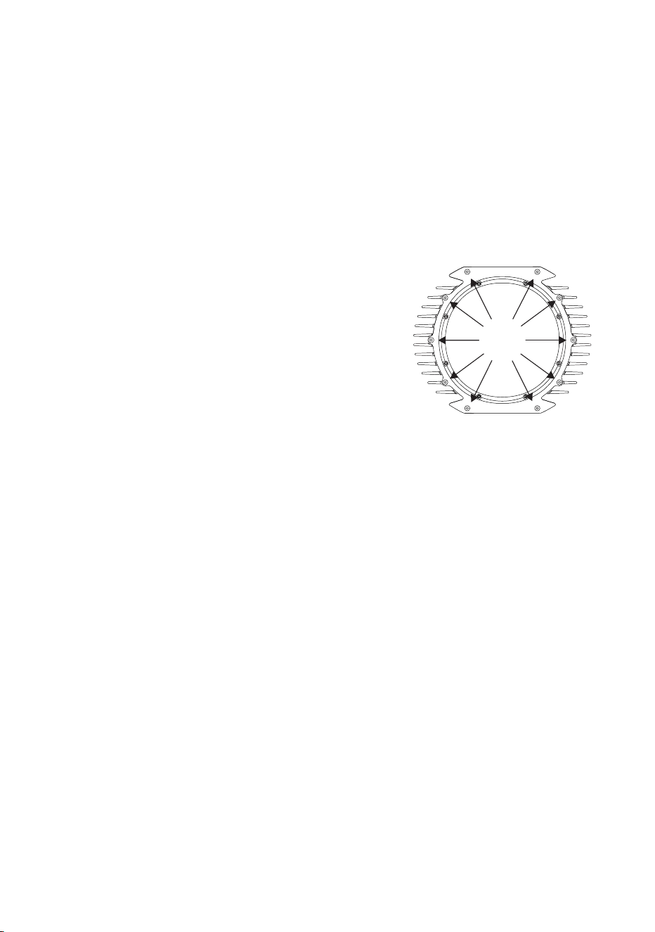
• When replacing the front cover, to avoid breaking the glass, tighten the
screws by working around in a circle.
Two water and oil-repellent GORE-TEX membrane air vents in the rear
cover of the Exterior 600 Compact allow air to pass through the housing.
This equalizes pressure differences and eliminates the potential for vacuum
that can suck moisture into the fixture if it is improperly installed or
maintained.
Gaskets
To maintain the fixture’s resistance to dust and moisture, it is important that
you replace gaskets carefully after removal. The silicone gaskets should
maintain their sealing ability for the life of the fixture. When servicing the
fixture, note the condition of the gaskets and replace any gasket that is
cracked, torn, brittle, or inflexible. Replacement gaskets may be ordered
from your Martin Architectural dealer.
The gaskets must extend 0.5 - 1 mm (1/64 - 1/32 in.) beyond the outside of
the casing. If you can feel the gasket when you run a finger across the joint,
that’s enough. A good seal will be maintained if the gaskets are flush with
the casing, but if they are below the casing’s edge, they can collapse into
the unit and let water in.

Seal maintenance 55
The recommended procedure for closing each of the 4 openings is the
same:
1. Insert the screws through all holes in the cover and gasket.
2. Place the cover firmly against the body. Adjust the straight sides of the
gasket so that they stick out a little, just enough so that you can feel the
edge of the gasket when you run a finger across the joint.
3. Cross-tighten the cover bolts evenly. The correct torque for these bolts
is 2 Nm (1.5 Ft-Lbs).
Cable glands
The supplied cables enter the fixture through cable glands that fit 5.5-10 mm
(1/4 - 2/5 in.) diameter cables. The gland must be replaced if the power or
data cable is replaced with a cable of a different diameter (larger than 10
mm or smaller than 5.5 mm (1/4 - 2/5 in.)), or if the data cable is replaced
with two separate cables. Replacement glands, available from electrical
suppliers, must have the following characteristics:
Temperature range 20 to 70 degrees Celsius (or better)
Ingress protection rating IP 67 or 68
Entry thread size PG 11
Minimum entry thread length 8 mm

56 Cleaning
Cleaning
Cleaning lenses
Clean the optical components carefully.
Remove smoke and other residues with cotton swabs or unscented tissues
moistened with isopropyl alcohol. A commercial glass cleaner may be used,
but residues must be removed with distilled water. Clean with a slow circular
motion from center to edge. Dry with a clean, soft and lint-free cloth or
compressed air.
Remove stuck particles with an unscented tissue or cotton swab moistened
with glass cleaner or distilled water. Do not rub the surface: lift the particles
off with a soft repeated press.
Cleaning the housing
The Exterior 600 Compact’s aluminum housing can be cleaned with mild
detergents such as those for washing cars.
Disconnect the fixture and allow it to cool.
Visually check that the seals are in good condition.
Rinse off loose dirt with a garden hose or low-pressure water spray. Do not
use a high-pressure spray.
Wash the aluminum using a mild detergent and a soft brush or sponge. Do
not use abrasive cleaners.
Rinse.

Firmware updates 57
Firmware updates
The latest Exterior 600 Compact firmware is available from the support area
of the Martin web site at http://www.martin.com. It can be installed using an
MP-2, or via a PC serial data link using a hardware interface supported by
the Software Uploader shareware (also available from the Martin web site).
The following devices are currently supported (in Version 5.5):
• DABS1
• ShowDesigner PCI DMX Interface Card (2048 channel version)
• LightJockey PCI DMX Interface Card (512 and 2048 channel versions)
• LightJockey PCMCIA DMX Interface
• LightJockey 4064 ISA DMX Interface Card (DJ and Club versions)
Note: If you are using an intermediate control system such as the
Martin Lighting Director (MLD) and the Martin Matrix, this must
be bypassed when updating fixture software via the DMX link.
These systems do not relay the update code correctly because
it is not a DMX-compliant signal.
When updating firmware, be sure to read the release notes to familiarize
yourself with any changes in functionality or any special instructions.
Note: Some firmware releases may require a boot mode upload, or a
boot sector update. In order to prepare the Exterior 600
Compact for this, a jumper inside the fixture must be set. In
these cases, follow the procedure in “When the fixture is not
responding (boot mode & boot sector upload)” on page 58.
Normal updates (DMX/Auto mode
upload)
To update fixture software, connect an upload device to the fixture as with a
DMX controller and perform a DMX mode upload as described in the upload
device’s documentation. There is no need to isolate the Exterior 600
Compacts from other types of fixtures on the serial data link.
When the upload is completed (and when booting up) the Exterior 600
Compact performs a check-sum test of the memory and then resets.
58 Firmware updates
In the unlikely event that a software upload is interrupted, the fixture must
be powered off for at least 10 seconds to force a check-sum test. You can
then repeat the DMX-mode upload. If an error occurs and the fixtures do not
reset, data was interrupted or corrupted during transmission.
When the normal method fails (boot
mode upload)
If an upload attempt is interrupted or corrupted, the fixture must be powered
off for at least 10 seconds before a second upload can be attempted. When
the fixture is powered on, the LEDs will blink yellow in preparation for the
second upload attempt. Perform a boot-mode upload (as described in the
upload device’s documentation).
When the fixture is not responding
(boot mode & boot sector upload)
If all else fails, the fixture is responding erratically or not at all, or when the
software update notes call for a boot sector update or boot mode upload:
1. Make sure the Exterior 600 Compact is isolated from AC power and has
been allowed to cool for at least 20 minutes.
2. Open the fixture by removing the ten 4mm Allen screws from the rear
cover plate.
3. Carefully remove the plate and seal.
4. To remove the printed circuit board from the fixture, remove the two
Philips screws from the aluminum bracket and pull the board out.
5. On the circuit board,
locate jumper PL121
(illustrated in “PCB layout”
on page 76) and move the
jumper to pins 1 and 2 as
shown here. This will
remove the write protection from the boot sector and place the fixture in
boot mode where it waits to receive new firmware.
6. Replace the PCB and apply power to the fixture.
7. Perform a boot mode upload as described in the upload device’s
documentation.
PL 104 PL 121
PIN #1
PIN #1
PL 104 PL 121
PIN #1
PIN #1
normal setting boot sector update

Firmware updates 59
8. When the upload is complete, disconnect the fixture from power and
allow to cool.
9. Remove the two screws from the aluminum bracket and pull the PCB
out.
10. Move the jumper at PL121 back to the “normal” position (pins 2 and 3).
11. Replace the PCB.
12. Before closing, check the condition of the seal. Replace with a new one
(P/N 20600020) if the seal is torn, cracked or brittle.
13. To close, insert the Allen screws through all holes in the cover and seal.
Place the cover firmly against the body. Adjust the straight sides of the
seal so that they stick out a little, just enough so that you can feel the
seal when you run a finger across the joint.
14. Cross-tighten the cover screws to a torque of 2 Nm (1.5 Ft-Lbs). At this
torque, the seal will be compressed by about one-third.
60 Adjusting field angle
Adjusting field angle
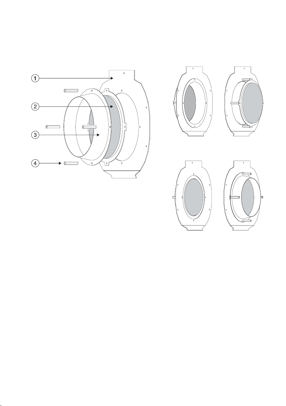
The Exterior 600 Compact’s field angle can be switched from 29° to 43° by
moving the fresnel lens from the front to the rear position. With the
accessory diffuser lens (not included), the field angle is 63°.
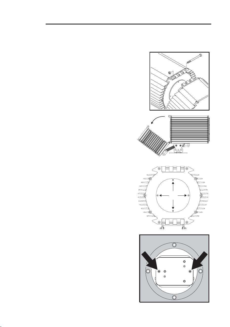
1. Disconnect the fixture from AC power.
Remove the front aluminum plate - not
the glass - by removing the 10 Allen
screws.
2. Remove the front lens assembly from
the fixture by removing 5 screws from
the lens assembly plate.
3. Remove the lens from the assembly
by unscrewing the hardware that fastens the lens bracket.
4. For a 29° beam angle (lens in forward position), place the lens on the
assembly plate so that the lens bracket is flush against the back of the
plate. Place the spacer cone over the lens. Align and fasten the parts
with 4 screws and spacer nuts. Screw the unused screws into the free
end of the spacer nuts to store them.
5. For a 43° beam angle (lens in rear position), place the spacer cone
through the assembly plate with the flange at the front and the narrow
end at the back. Fasten the spacer cone with 4 screws and spacer nuts.
Position the lens on top of the spacer nuts with the bracket against the
spacer cone and fasten with 4 screws.
6. For a 63° beam angle, substitute the diffuser lens for the fresnel lens
and install in either position as described above.
7. Place the front lens assembly back in the fixture and fasten with 5
screws.
8. Before closing, check the condition of the seal. Replace with a new one
(P/N 20600020) if the seal is torn, cracked or brittle.
9. To replace the front plate, insert the Allen screws through all holes in the
plate and seal. Place the plate firmly against the body. Adjust the
Adjusting field angle 61
straight sides of the seal so that they stick out a little bit, just enough so
that you can feel the seal when you run a finger across the joint.
10. Cross-tighten the Allen screws with a torque of 2 Nm (1.5 Ft-Lbs). With
this torque, the seal will be compressed by about one-third.
1. lens assembly plate
2. lens and bracket
3. spacer cone
4. spacer nut
43° configuration
29° configuration
62 Lamp maintenance
Lamp maintenance
This chapter describes how to install and adjust a lamp. It contains the
following sections:
• “Compatible lamps”
• “Maximum lamp usage”
• “Installing the lamp” on page 64
Compatible lamps
The Exterior 600 Compact is designed to use the lamps listed below.
Installing other lamps may damage the fixture.
Note: This data is subject to change. Refer to the manufacturer
supplied specification for up-to-date information.
Maximum lamp usage
The quartz bulb weakens over time, significantly increasing the risk of lamp
explosion. Replace the lamp no later than indicated in the table above. We
recommend that you replace all the lamps in an installation together. This
will simplify keeping track of when you need to change the lamps in
installations with many fixtures.
Lamp Average life Replace by Color temp. Output
Philips MSD 575 3000 hours 3200 hours 6000K 78 lm/w
Philips MSR 575/2 1000 hours 1200 hours 7200K 85 lm/w
Osram HSR 575/2 1000 hours 1200 hours 6000K 85 lm/w
Osram HSD 575 3000 hours 3600 hours 7200K 78 lm/w
Lamp maintenance 63
Resetting or checking the lamp hours counter
using MUM
The Exterior 600 Compact has a built-in counter that you can check or reset
using the MUM application on a personal computer. When you install a new
lamp we recommend that you reset the fixture’s “Total lamp hours” counter.
Support for the MUM application is available from Version 2 of the Exterior
600 Compact software.
To get started:
1. Connect a DABS1 adaptor to your PC.
2. Connect the DABS1 adaptor to your Exterior 600 Compact.
3. Power on the Exterior 600 Compact and start the MUM application. The
application will automatically detect an Exterior 600 Compact if it is
powered-on and connected to your computer via a DABS1 adaptor. It
will also retrieve the current settings on the fixture and display them.
4. Using MUM, click on the Fixture information button:
5. The Total Lamp-on hours will be displayed and can be reset using the
button to the right of the field.
64 Lamp maintenance
Installing the lamp
WARNING! Always disconnect the fixture from AC power and allow it to
cool for 20 minutes before installing the lamp.
1. Isolate the fixture from AC power. If it is
hot, allow it to cool for at least 20 minutes
before proceeding. The lamp is under
high pressure when hot and can explode:
use safety goggles to protect your eyes.
2. Remove the nut from the M10 bolt at the
top of the fixture and remove the bolt.
3. Loosen the bottom bolt slightly, if
necessary, and tilt the rear section
back no more than 45° to avoid
damaging the electrical conduit
beneath the fixture.
4. Remove the four 5mm Allen
screws from the lamp access plate.
Remove the access plate and its
rubber seal.
5. Remove the 2 Phillips screws from
the lamp-socket assembly. Gently
pull out the assembly.
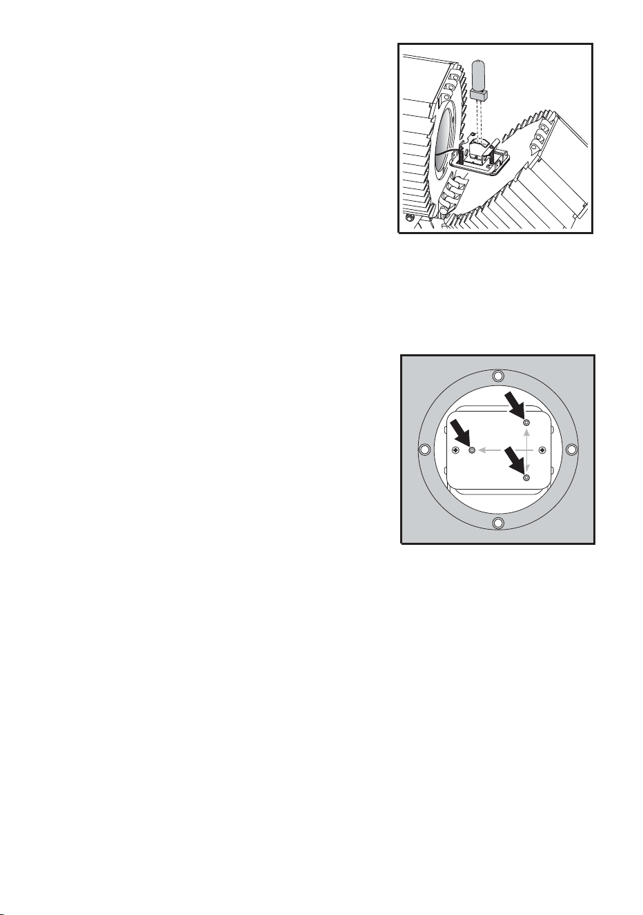
Lamp maintenance 65
6. Remove the old lamp from the
socket.
7. Holding the new lamp by its ceramic
base - do not touch the glass -
insert it firmly and squarely into the
lamp socket.
8. Clean the glass bulb with the wipe
supplied with the lamp, particularly
if your fingers touched the glass. A
clean, lint-free cloth wetted with
alcohol may also be used.
9. Re-insert the lamp assembly. Replace the 2 Phillips screws.
10. The lamp holder is adjusted at the factory; but precise alignment may be
necessary due to slight variations between lamps:
a. Apply power to the fixture.
b. Center the hot-spot (the brightest
part of the beam) by turning the 3
Allen/hex screws one at a time to
move the hot-spot diagonally
across the beam. If there is no
hot-spot, adjust until the light is
even.
c. To reduce the hot-spot, pull the
lamp back towards you by turning
all three Allen screws clockwise 1/4-turn at a time until the light is
evenly distributed.
d. If the light is brighter around the edge than it is in the center, or if light
output is low, the lamp is too far back in the reflector. Move the lamp
forward by turning the adjustments screws counterclockwise 1/4-turn
at a time until the light is bright and evenly distributed.
e. Disconnect the fixture from power and allow to cool.
11. Check the condition of the lamp access seal. Replace with a new one
(P/N 20620050) if the seal is torn, cracked or brittle.
12. Place the seal on the back of the lamp access plate. Insert the 4 Allen
screws through the plate and install. Tighten the Allen screws to a torque
of 2 Nm (1.5 Ft-Lbs). At this torque, the seal will be compressed by
about one-third.
13. Tilt the rear section into position and replace the long bolt and lock nut.

66 Lamp maintenance
14. Reset the lamp-hours counter using a MUM or MP-2 Uploader. See
“Resetting or checking the lamp hours counter using MUM” on page 63.

Maintaining the electrical system 67
Maintaining the
electrical system
This section describes electrical maintenance procedures that can be
performed by the user. It contains the following sections:
• “Replacing fuses”, below
• “Changing the power settings” on page 69
• “Installing a cord cap on the mains lead” on page 17
Refer all service not described here to a qualified Martin technician.
Warning! Disconnect the fixture from power before removing any cover.
Always disconnect the fixture from AC power and allow it to
cool for 20 minutes before servicing.
Replacing fuses
The Exterior 600 Compact has 4 fuses: a mains fuse - 6.3 AT (Martin P/N
05020020) - and three fuses on the PCB, one for each of the fixture’s low-
voltage power supplies:
• 5 AT (Martin P/N 05020018), at position F601 on the PCB
• 4 AT 5X20 (Martin P/N 05020016), at position F602 on the PCB
• 0.315 AT (Martin P/N 05020004), at position F603 on the PCB
The locations of the fuses on the PCB are illustrated in “PCB layout” on
page 76.
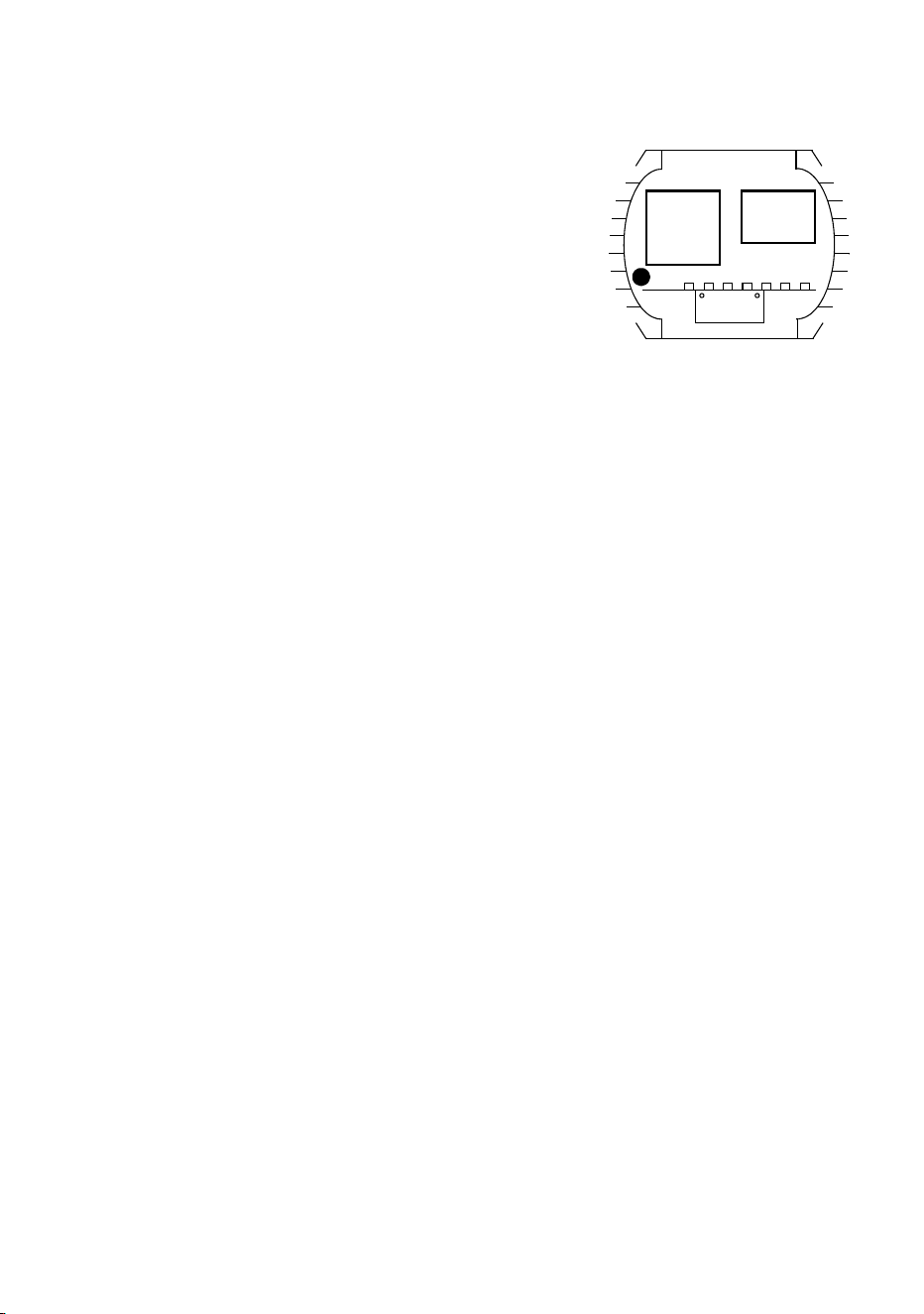
68 Maintaining the electrical system
Mains fuse
To replace the mains fuse:
1. Make sure the Exterior 600
Compact is isolated from AC power
and has cooled for at least 20
minutes.
2. Remove the ten 4mm Allen screws
from the rear cover plate. Carefully
remove the plate and seal.
3. The main fuse is located in a fuse
holder inside the electronics section, to the left of the ballast. Using a
flathead screwdriver, open the fuse holder and remove the fuse.
4. Replace the defective fuse with one of the same size and rating.
Replace the fuse holder.
5. Before closing the cover plate, check the condition of the seal. Replace
with a new one (P/N 20600020) if the seal is torn, cracked or brittle.
6. To close, insert the Allen screws through all holes in the cover and seal.
Place the cover firmly against the body. Adjust the straight sides of the
seal so that they stick out a little, just enough so that you can feel the
seal when you run a finger across the joint.
7. Cross-tighten the cover screws evenly to a torque of 2 Nm (1.5 Ft-Lbs).
At this torque, the seal will be compressed by about one-third.
Fuses on the PCB
To replace any of the fuses on the PCB:
1. Make sure the Exterior 600 Compact is isolated from AC power and has
cooled for at least 20 minutes.
2. To open the fixture, remove the ten 4mm Allen screws from the rear
cover plate. Pull off the plate and seal.
3. To remove the printed circuit board from the fixture, remove the 2 Philips
screws from the aluminum bracket and pull the board out.
4. You will find a diagram of the PCB, that includes the fuses, in “PCB
layout” on page 76. Locate and replace the defective fuse with one of
the same size and rating.
5. Replace the PCB.
Ballast
Tra ns-
former
Mains
fuse holder
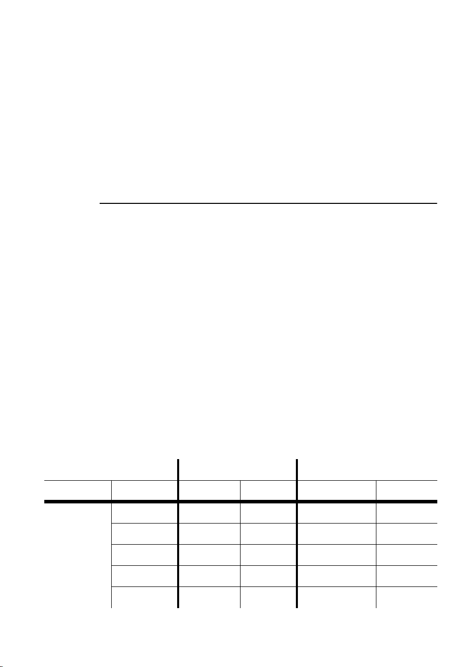
Maintaining the electrical system 69
6. Before closing the cover plate, check the condition of the seal. Replace
with a new one (P/N 20600020) if the seal is torn, cracked or brittle.
7. To close, insert the Allen screws through all holes in the cover and seal.
Place the cover firmly against the body. Adjust the straight sides of the
seal so that they stick out a little, just enough so that you can feel the
seal when you run a finger across the joint.
8. Cross-tighten the cover screws evenly to a torque of 2 Nm (1.5 Ft-Lbs).
At this torque, the seal will be compressed by about one-third.
Changing the power settings
Warning! The voltage and frequency settings must match the local AC
power supply!
The factory-set power supply tappings are printed on the serial number label
on the back plate. Operating at the incorrect power setting can result in poor
light output, greatly reduced lamp life, overheating and damage to the
fixture. If the setting does not match your local AC voltage and frequency,
then the power supply must be retapped.
Warning! The fixture’s power supply must be rewired by a qualified
installer or technician.
Adjusting power
This procedure applies to all models except those factory wired for 277 V
supply (see the serial number label on the fixture). If the Exterior 600
Compact model is factory wired for 277 volt supply then contact your Martin
dealer for assistance.
Local AC Supply Transformer Ballast
Frequency Voltage Setting Terminal Setting Terminal
50 Hz 200-210 V 210 V 4 200 V / 50 Hz 7
210-220 V 210 V 4 230 V / 50 Hz 10
220-235 V 230 V 6 230 V / 50 Hz 10
235-240 V 230 V 6 245 V / 50 Hz 12
240-260 V 250 V 8 245 V / 50 Hz 12
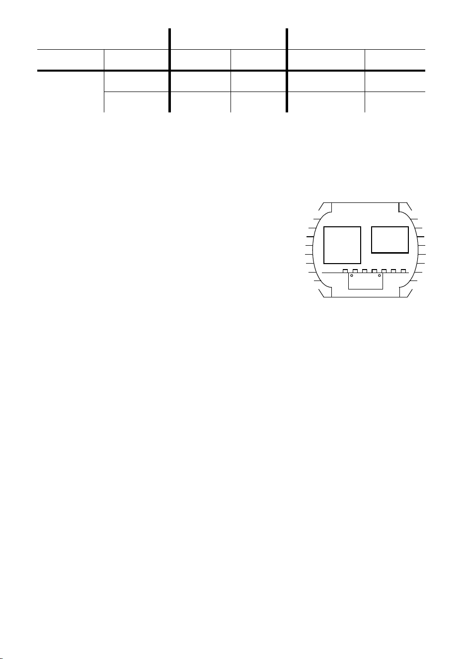
70 Maintaining the electrical system
Warning! Disconnect the fixture from AC power before removing any
cover.
1. Make sure the Exterior 600 Compact is isolated from AC power and has
cooled for at least 20 minutes.
2. Remove the 10 Allen screws from the
rear cover plate. Carefully remove the
plate and seal.
3. Find the row in the above table with the
local AC frequency and voltage. Follow
the row to the right to find the correct
transformer and ballast tappings. For
example, with a local AC supply of 230V,
50 Hz, the correct transformer tapping is terminal 6 and the correct
ballast tapping is terminal 10.
4. To tap the transformer, move the 2 BROWN wires to the correct
terminal. Terminals are identified on the transformer in front of the
connection tabs.
5. To tap the ballast, move the single BROWN wire to the correct terminal.
6. Check the condition of the cover plate seal. Replace with a new one
(P/N 20600020) if the seal is torn, cracked or brittle.
7. Insert the Allen screws through all holes in the cover and the seal. Place
the cover firmly against the body.
8. Adjust the straight sides of the seal so that they stick out a little, just
enough so that you can feel the seal when you run a finger across the
joint.
9. Cross-tighten the cover bolts evenly. The correct torque for these bolts
is 2 Nm (1.5 Ft-Lbs). At this torque, the seal will be compressed by about
one-third.
60 HZ 200-217 V 210 V 4 208 V / 60 Hz 4
217-240 V 230 V 6 227 V / 60 Hz 7
Local AC Supply Transformer Ballast
Frequency Voltage Setting Terminal Setting Terminal
Ballast
Trans -
former

Maintaining the electrical system 71
Installing a battery on the PCB
The Exterior 600 Compact’s built-in clock, which can be used to start and
stop operation in stand-alone mode, requires a 3V battery (P/N 05801001)
on the PCB in order to keep time when the fixture is powered off.
The battery mounts on the circuit board at position BAT101, which is located
right behind the sensor inputs at PL251 and PL252, on top of IC124. The
position is indicated by a ring of the same size as the battery. The positive
pole is indicated on the print and is the position closest to the relay.
To:
• Install the battery, heat the existing solder on the bottom of the circuit
board and insert the pins from the top, one at a time.
• Prevent accidental discharge when storing in an antistatic bag, we
recommend placing a drop of silicone over the solder connections.
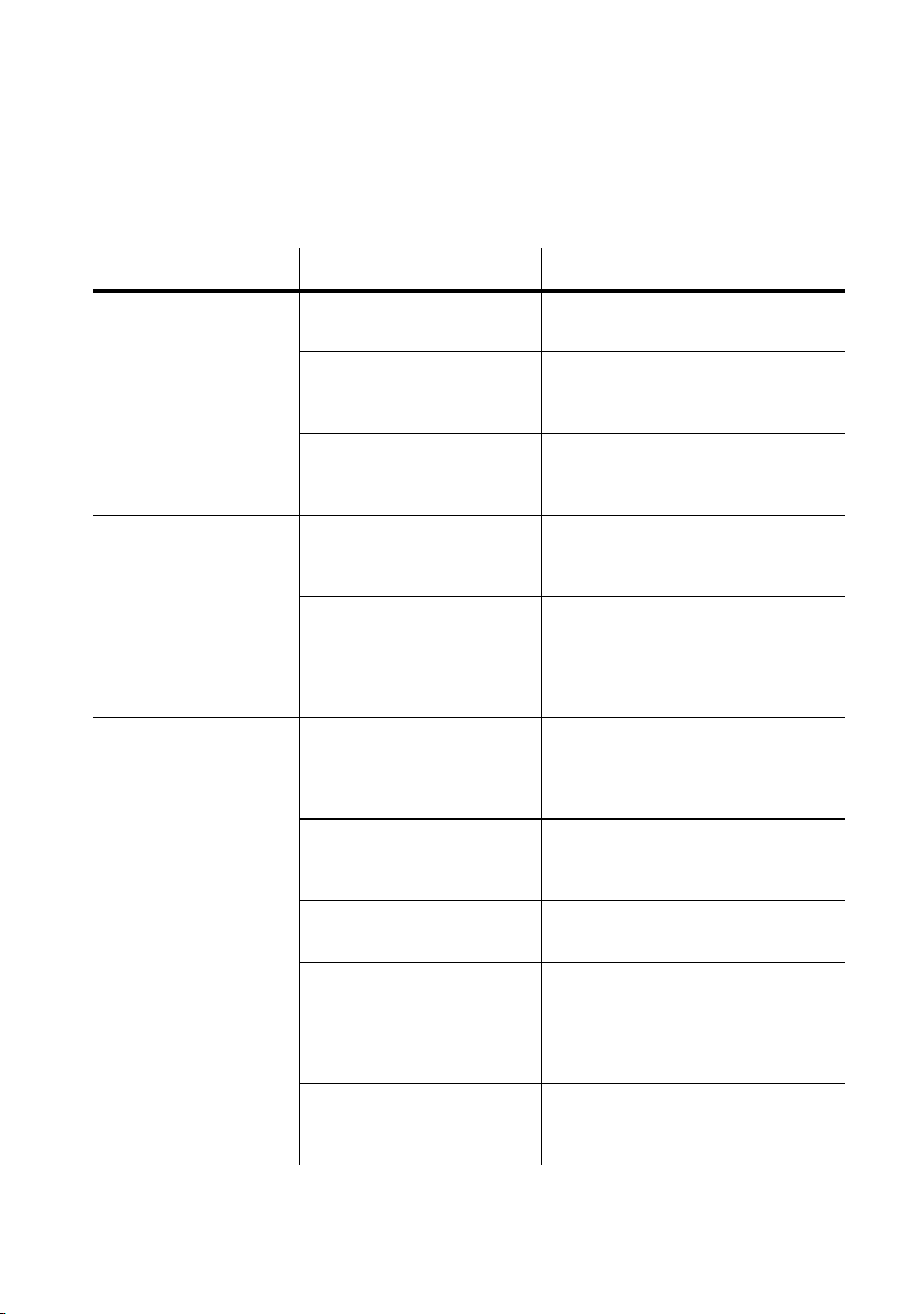
Troubleshooting
Problem Probable cause(s) Remedy
One or more of the
fixtures is completely
dead.
Fixture not powered on. Check that power is switched on
and cables are plugged in.
Primary fuse blown
(located besides the
ballast).
Disconnect fixture and replace
fuse.
Secondary fuse(s) blown
(located on PCB inside
the fixture base).
Disconnect fixture. Check fuses
on PCB and replace.
Fixtures reset
correctly but all
respond erratically or
not at all to the
controller.
The controller is
disconnected from the
data link.
Connect controller.
XLR pin-out of the
controller does not match
pin-out of the first fixture
on the link (signal is
reversed).
Install a phase-reversing cable
between the controller and the
first fixture on the link.
Fixtures reset
correctly but some
respond erratically or
not at all to the
controller.
Bad data link connection Inspect connections and cables.
Correct poor connections.
Repair or replace damaged
cables.
Data link not terminated
with 120Ω termination
plug.
Insert termination plug in output
jack of the last fixture on the
link.
Incorrect addressing of
the fixtures.
Check fixture address and
protocol settings.
One of the fixtures is
defective and disturbs
data transmission on the
link.
Bypass one fixture at a time until
normal operation is regained.
Have the defective fixture
serviced by a qualified
technician.
XLR pin-out on fixtures
does not match (pins 2
and 3 reversed).
Install a phase-reversing cable
between the fixtures.
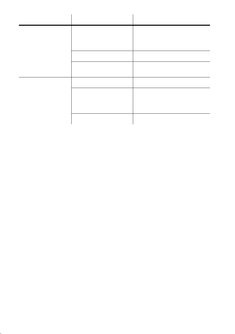
Troubleshooting 73
Lamp does not
strike.
Ballast and transformer
settings do not match
local AC voltage and
frequency.
Disconnect fixture. Check
ballast and transformer settings
and correct if necessary.
Lamp missing or blown. Install new lamp.
Lamp is too hot. Allow lamp to cool for at least 8
minutes.
Lamp cuts out
intermittently.
Fixture is too hot. Allow fixture to cool.
Ballast and transformer
settings do not match
local AC voltage and
frequency.
Disconnect fixture. Check
ballast and transformer settings
and correct if necessary.
Defective fan. Refer to service technician.
Problem Probable cause(s) Remedy

74 Troubleshooting

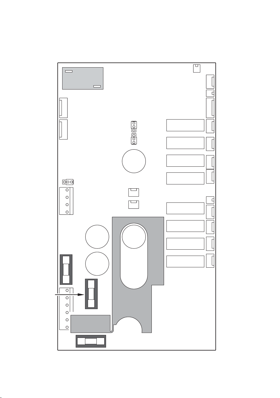
76 PCB layout
PCB layout
PL 511
PL 501
PL 441
PL 431
PL 306
PL 421
PL 421
PL 411
PL 401
PL 701
PL 301
304
PL
PL 303
PL 252
PL 251
PL 251
PL 105
PL 107
Sens Out (LS1)
Sens Out (LS1)
Sens Lamp (LS2)
Sens Lamp (LS2)
Switch
Hall Sensor
Hall Sensor
Link
0.315 AT
4AT
5AT
Yellow
Magenta
Cyan
LED Display
LED Display
Fan Rear
Fan Rear
Fan Front /
Temp sensor
Fan Front /
Temp
sensor
Brown
Brown
PL 121
Hard Boot Jumper
PL 121
Hard
Boot Jumper
PL 231
PL 611
AC Input
AC Input
PL 104
Flash Write
PL 104
Flash
Write
Enable
PL 232
TX Enable
PL 232
TX
Enable
Disable
Enable
Disable
Enable
Disable
Ext600 Print lay-out.eps

Specifications 77
Specifications
Physical
Length.............................................................................................. 576 mm (22.7 in.)
Width................................................................................................ 375 mm (14.8 in.)
Height .............................................................................................. 421 mm (16.6 in.)
Weight................................................................................................... 42.7 kg (94 lb)
Source
Lamp................................................................................................. 575 W discharge
Base ................................................................................................................. GX 9.5
Approved models............................................................................Philips MSR 575/2
...........................................................................................................Philips MSD 575
........................................................................................................Osram HSR 575/2
...........................................................................................................Osram HSD 575
Control ........................................................................ automatic and/or remote on/off
Dynamic effects
Cyan filter.......................................................................................................0 - 100%
Magenta filter.................................................................................................0 - 100%
Yellow filter.....................................................................................................0 - 100%
Control & Programming
Control options...................................................DMX-512, stand-alone, master/slave
Receiver........................................................................................................... RS-485
Setting and addressing................................................................... MP-2, DAD, MUM
Firmware update.......................................................................... Serial upload (MUF)
Stand-alone triggers..............internal real-time clock with timer and light-level sensor
Stand-alone memory....................................................................................20 scenes
Data in/out ........... 1.8 m (5.9 ft) trailing cable w/ 3-pin XLR male & 3-pin XLR female
DMX channels ........................................................................................................ 4/5
Installation
Mounting points .....................4 curved 10 mm (0.4 in) slots on 85 mm (3.4 in) radius
Orientation ............................................................................................................. any
Swivel ............................................................................................................... +/- 25°
Tilt (pedestal mounted) ..................................................................................... +/- 40°
Minimum distance to combustible materials ............................................... 1 m (39 in)
Minimum distance to illuminated surfaces .................................................. 1 m (39 in)

78 Specifications
Thermal
Maximum ambient temperature (Ta) .....................................................40° C (104° F)
Maximum surface temperature .............................................................90° C (194° F)
Cooling ....................................................................................................... convection
Average power consumption
@ 230 V, 50 Hz ....................................................................................... 650 W, 3.5 A
@ 245 V, 50 Hz ....................................................................................... 640 W, 3.3 A
@ 208 V, 60 Hz ....................................................................................... 620 W, 3.9 A
Average heat dissipation
@ 230 V, 50 Hz ................................................................................... 2218 BTU/hour
@ 245 V, 50 Hz ................................................................................... 2183 BTU/hour
@ 208 V, 60 Hz ....................................................................................2115 BTU/hour
Note: Data extrapolated from average power consumption
AC Supply
AC input ................................................1.8 m (5.9 ft) trailing cable (without cord cap)
Operating range .................................................... 200-250V/50Hz & 200-240V/60Hz
Construction
Housing ......................................................................................... extruded aluminum
Finish.......................................................................anodized, natural aluminum color
Base .............................................................................. 6 mm (0.24 in) stainless steel
Front glass .......6 mm (0.24 in) anti-reflection coated (except 12° and 100° versions)
Protection factor .................................................................................................. IP 65
Listings
ETL, ETLC, CE
Included items
User manual..........................................................................................P/N 35000082
Philips MSD575 ....................................................................................P/N 97010205

Specifications 79
Accessories
68° diffuser lens lit ................................................................................ P/N 91610017
103° prismatic lens kit........................................................................... P/N 91610027
5500-4200K Color Temperature Correction Kit..................................... P/N 91611036
MC-X Controller, 220 - 245 V, 50 Hz .................................................... P/N 90718200
MC-X Controller, 110 - 120 V, 60 Hz..................................................... P/N 90718300
Snoot/barn door kit ............................................................................... P/N 91611029
Extensions to snoot/barn door kit ......................................................... P/N 91611030
DMX Address Device (DAD)................................................................. P/N 90758430
Multi Utility Manager (MUM) ................................................................. P/N 90758090
MP-2 Uploader...................................................................................... P/N 90758420
Philips MSD 575 ................................................................................... P/N 97010202
Philips MSR 575/2 ................................................................................ P(N 97010201
Osram HSR 575/2 ................................................................................ P/N 97010200
Osram HSD 575 ................................................................................... P/N 97010207
Sealing kit ............................................................................................. P/N 91611017
Lamp replacement kit ........................................................................... P/N 91611018
Lamp access seal................................................................................. P/N 20620050
6.3 AT mains fuse................................................................................. P/N 05020020
5 AT fuse (PCB position F601) ............................................................. P/N 05020018
4 AT 5X20 fuse (PCB position F602).................................................... P/N 05020016
0.315 AT fuse (PCB position F603) ...................................................... P/N 05020004
Ordering information
Exterior 600 Compact, 29°/43°, 230V / 50Hz ....................................... P/N 90505200
Exterior 600 Compact, 29°/43°, 245V / 50Hz ....................................... P/N 90505202
Exterior 600 Compact, 29°/43°, 208V / 60Hz ....................................... P/N 90505204

www.martin-architectural.com • Olof Palmes Allé 18 • 8200 Aarhus N • Denmark
Tel: +45 8740 0000 •
Fax +45 8740 0010
