
Martin Exterior 50 IP68
Martin Exterior 100 IP68
System
User Manual
TM
TM
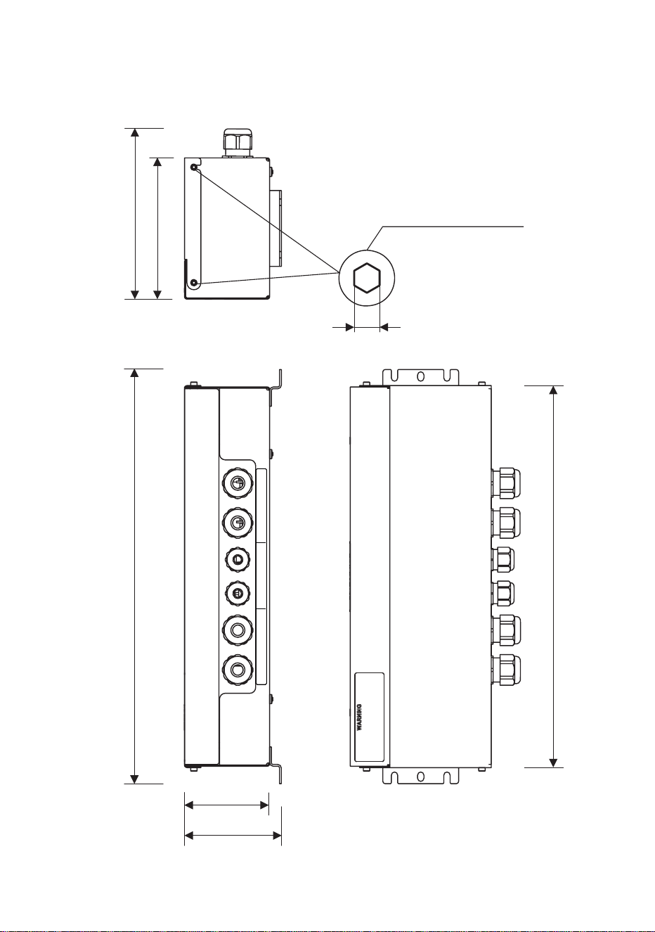
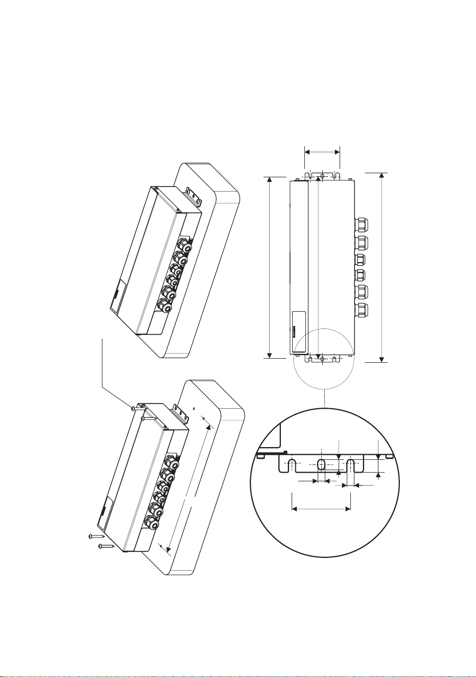
Dimensions
All dimensions are in millimeters
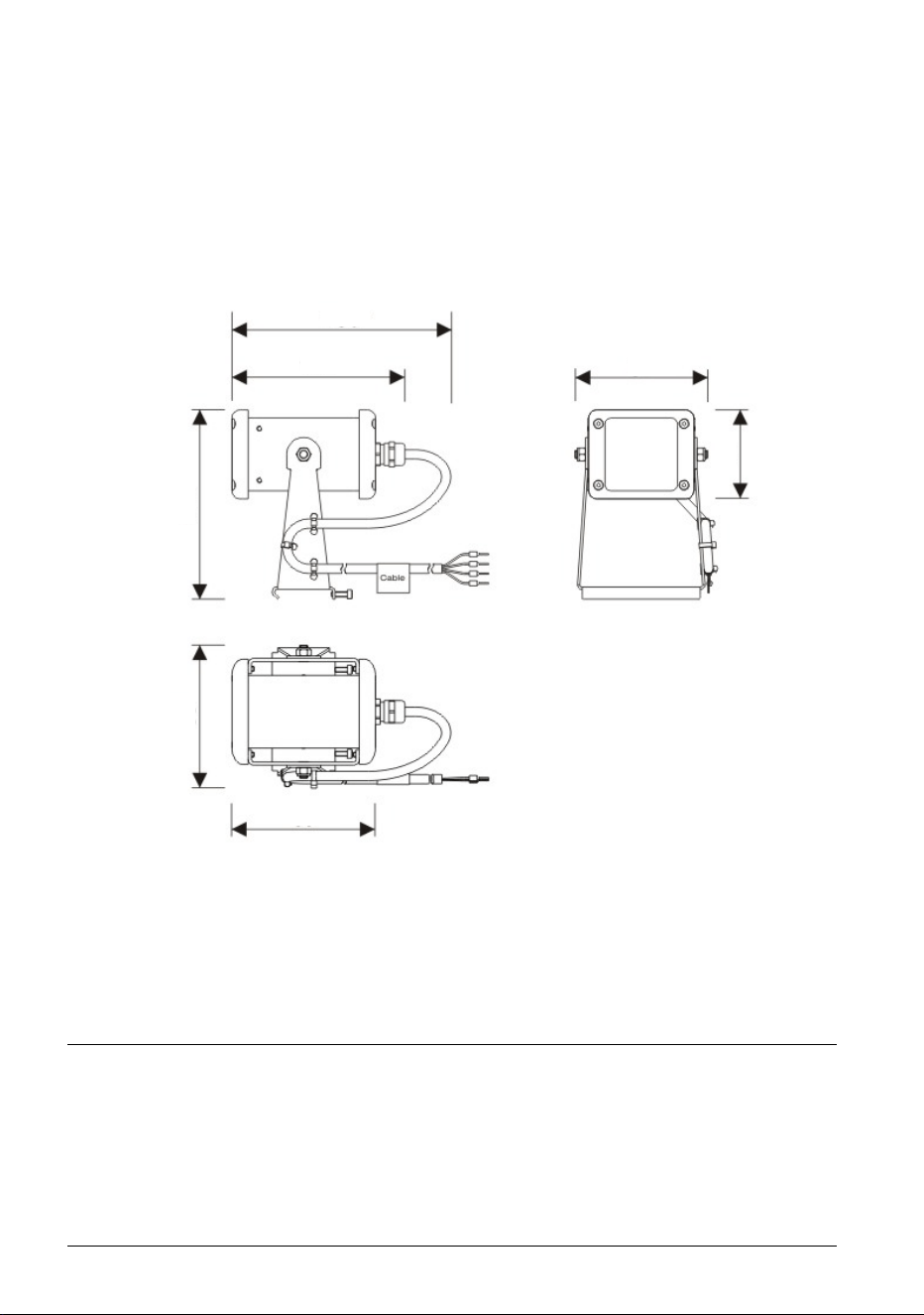
Exterior 50 IP68 Luminaire
*Approximate figure
allowing for cable exit
130*
107
82
89
117
88
55
© 2012 Martin Professional A/S. Information subject to change without notice. Martin Professional
A/S and all affiliated companies disclaim liability for any injury, damage, direct or indirect loss,
consequential or economic loss or any other loss occasioned by the use of, inability to use or
reliance on the information contained in this document. The Martin logo, the Martin name and all
other trademarks in this document pertaining to services or products by Martin Professional A/S or
its affiliates and subsidiaries are trademarks owned or licensed by Martin Professional A/S or its
affiliates or subsidiaries.
P/N 35000255, Rev. A
Dimensions 3
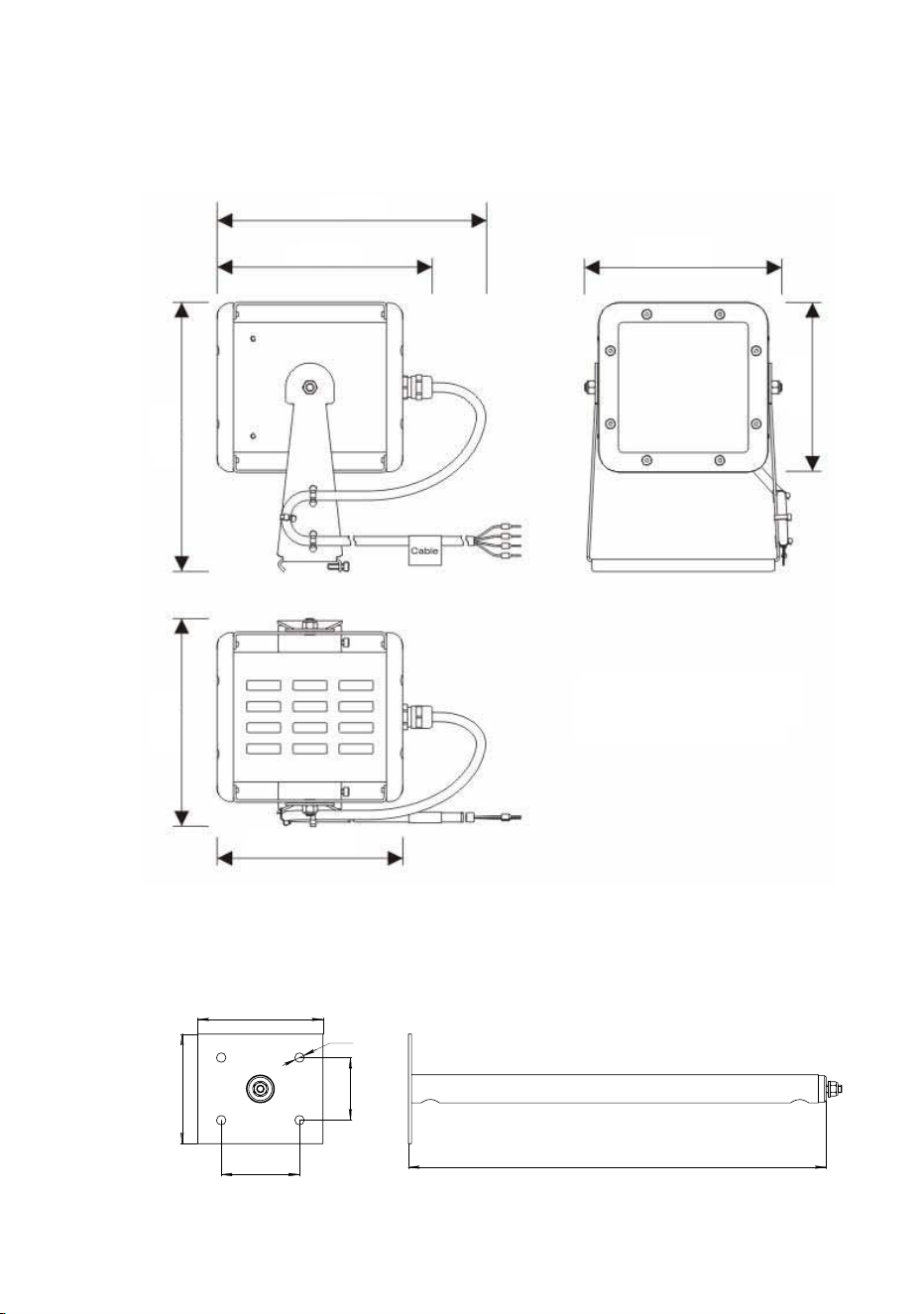
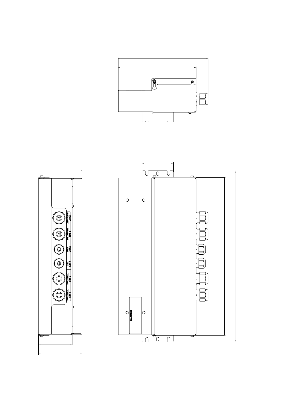
Exterior 100 IP68 Luminaire
*Approximate figure
allowing for cable exit
267
70
50
8
0
40
Z
6
Standard mounting post
70
80
50
40
Ø6
267
165*
122
105
133
114
128
166
4 Martin Professional™ Exterior 50 & 100™ system user manual
Exterior 50 and 100 Splitter
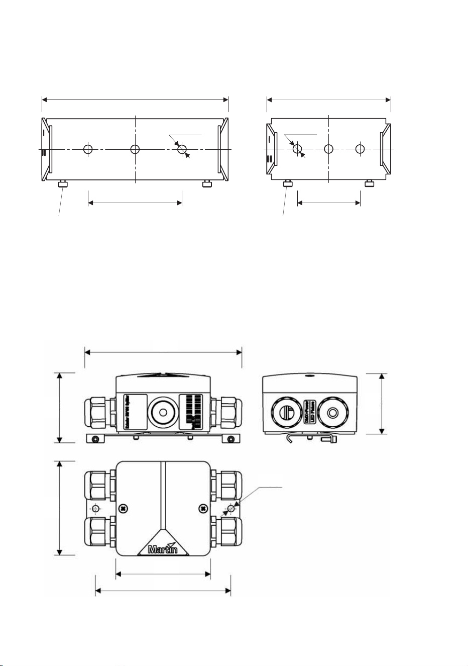
Exterior 50 and 100 Mounting bracket bases
Exterior 100 Mounting bracket Exterior 50 Mounting bracket
M3 screw for mounting on DIN rail M3 screw for mounting on DIN rail
119
60 40
79
Ø 5.5 Ø 5.5
119 79
60 40
Ø5.5
133
59
52
Ø5.5
Ø5.5
80
80
115
Dimensions 5
Exterior 50 and 100 PSU (EU model, 50/60 Hz)
DMX+P
ower
Line 1
DMX+Power
Line 2
Line 2
DMX
Line
2
DMX
Line
1
100-240VAC
100-240VAC
Line 2
100-240V
AC
100-240VAC
Line 1
146
121
4x M3 screws DIN 912
2.5
355 328
73
83
6 Martin Professional™ Exterior 50 & 100™ system user manual
355
328
65
70
90
161
186
Exterior 50 and 100 PSU (US model, 60 Hz)
186
161
65
355
328
70
90

Contents
Dimensions . . . . . . . . . . . . . . . . . . . . . . . . . . . . . . . . . . . . . . . . . . . . . . . . . .2
Safety information . . . . . . . . . . . . . . . . . . . . . . . . . . . . . . . . . . . . . . . . . . . . .8
Introduction . . . . . . . . . . . . . . . . . . . . . . . . . . . . . . . . . . . . . . . . . . . . . . . . .12
Unpacking . . . . . . . . . . . . . . . . . . . . . . . . . . . . . . . . . . . . . . . . . . . . . . . .12
General information . . . . . . . . . . . . . . . . . . . . . . . . . . . . . . . . . . . . . . . . . . .13
Components in the system . . . . . . . . . . . . . . . . . . . . . . . . . . . . . . . . . . . .13
System power: general . . . . . . . . . . . . . . . . . . . . . . . . . . . . . . . . . . . . . .13
System control: general . . . . . . . . . . . . . . . . . . . . . . . . . . . . . . . . . . . . . .14
System layout: general . . . . . . . . . . . . . . . . . . . . . . . . . . . . . . . . . . . . . . .15
Installation and connections: general . . . . . . . . . . . . . . . . . . . . . . . . . . . .22
Installing Power Supply Units . . . . . . . . . . . . . . . . . . . . . . . . . . . . . . . . . .27
Physically installing a PSU . . . . . . . . . . . . . . . . . . . . . . . . . . . . . . . . . . . .27
Connecting a PSU . . . . . . . . . . . . . . . . . . . . . . . . . . . . . . . . . . . . . . . . . .29
Installing Splitters . . . . . . . . . . . . . . . . . . . . . . . . . . . . . . . . . . . . . . . . . . . .42
Physically installing a Splitter . . . . . . . . . . . . . . . . . . . . . . . . . . . . . . . . . .42
Connecting a Splitter . . . . . . . . . . . . . . . . . . . . . . . . . . . . . . . . . . . . . . . .44
Installing Luminaires . . . . . . . . . . . . . . . . . . . . . . . . . . . . . . . . . . . . . . . . . .49
Physically installing Luminaires . . . . . . . . . . . . . . . . . . . . . . . . . . . . . . . .49
Connecting Luminaires . . . . . . . . . . . . . . . . . . . . . . . . . . . . . . . . . . . . . .54
Installing light shields . . . . . . . . . . . . . . . . . . . . . . . . . . . . . . . . . . . . . . . .59
Checking and monitoring the installation . . . . . . . . . . . . . . . . . . . . . . . . .60
System status indicators in a PSU . . . . . . . . . . . . . . . . . . . . . . . . . . . . . .60
System status indicators in a Splitter . . . . . . . . . . . . . . . . . . . . . . . . . . . .61
Setup . . . . . . . . . . . . . . . . . . . . . . . . . . . . . . . . . . . . . . . . . . . . . . . . . . . . . . .62
Setting up for DMX control . . . . . . . . . . . . . . . . . . . . . . . . . . . . . . . . . . . .62
Setting up using the remote control . . . . . . . . . . . . . . . . . . . . . . . . . . . . .64
Setting up via RDM using Martin M-PC™ . . . . . . . . . . . . . . . . . . . . . . . .67
Operation . . . . . . . . . . . . . . . . . . . . . . . . . . . . . . . . . . . . . . . . . . . . . . . . . . .70
Ambient temperatures . . . . . . . . . . . . . . . . . . . . . . . . . . . . . . . . . . . . . . .70
DMX control . . . . . . . . . . . . . . . . . . . . . . . . . . . . . . . . . . . . . . . . . . . . . . .70
Using Martin M-PC™ for DMX control . . . . . . . . . . . . . . . . . . . . . . . . . . .71
DMX protocols . . . . . . . . . . . . . . . . . . . . . . . . . . . . . . . . . . . . . . . . . . . . . . .73
RGBW Luminaires . . . . . . . . . . . . . . . . . . . . . . . . . . . . . . . . . . . . . . . . . .73
White (CW, NW and WW) Luminaires . . . . . . . . . . . . . . . . . . . . . . . . . . .73
Service . . . . . . . . . . . . . . . . . . . . . . . . . . . . . . . . . . . . . . . . . . . . . . . . . . . . .74
Cleaning . . . . . . . . . . . . . . . . . . . . . . . . . . . . . . . . . . . . . . . . . . . . . . . . . .74
Software installation . . . . . . . . . . . . . . . . . . . . . . . . . . . . . . . . . . . . . . . . .74
Troubleshooting . . . . . . . . . . . . . . . . . . . . . . . . . . . . . . . . . . . . . . . . . . . . .76
Specifications . . . . . . . . . . . . . . . . . . . . . . . . . . . . . . . . . . . . . . . . . . . . . . .77
8 Martin Professional™ Exterior 50 & 100™ system user manual
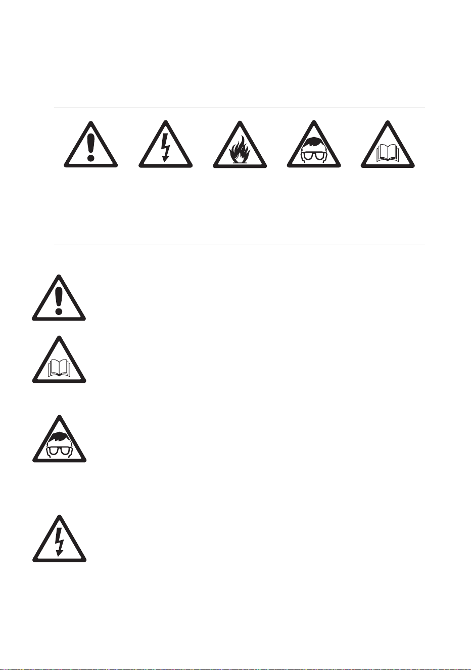
Safety information
The following symbols are used to identify important safety information in
this guide:
Warning! The Martin™ Exterior 50 & 100 system is not for household
use.
Warning! Read this guide before operating the system, follow the
safety precautions listed in this section of the guide, and observe all
warnings in this guide and printed on devices. Install and operate the
system only as described in this guide and in accordance with local
laws and regulations. Refer any operation not described in this guide
to a qualified technician.
Warning! There are no user-serviceable parts inside Exterior 50 &
100 Luminaires. Refer all service to Martin™ or its authorized service
agents.
Warning! Risk Group 3 (high risk) LED product according to
EN 62471. Do not view the light output with optical instruments or
any device that may concentrate the beam.
If you have questions about how to operate the system safely, please
contact your Martin supplier or call the Martin 24-hour service hotline on
+45 8740 0000, or in the USA on 1-888-tech-180.
PROTECTION FROM ELECTRIC SHOCK
• Isolate the entire system from AC mains power and make sure that
power cannot be applied during work on the system.
• Use only a single-phase, three-wire AC mains power source that
complies with local building and electrical codes, that has both overload
and ground-fault (earth-fault) protection, and that is within the voltage
and frequency range specified on the serial number label on the PSU.
Danger! Risk of
personal injury.
Danger! Risk of
electric shock.
Danger! Risk of
fire.
Warning!
LED light
emission. Do
not concentrate
the light beam.
Warning! Refer
to user
documentation
before
installing,
powering or
servicing.

Safety information 9
• Ensure that the system is electrically connected to ground (earth) as
described in this guide.
• Either power outlet sockets or hard-wired circuits that incorporate power
on/off switches must be used to supply the system with power. Power
plugs and/or power on/off switches must be easily accessible so that
the system can be isolated from power quickly.
• Provide a means of locking out power (ensure that power can be shut
down and is impossible to reapply, even accidentally) during service.
• Connect the PSU to AC mains power and relay power from one PSU to
another using only 3-conductor neoprene- or hypalon-jacket cable that
is heat resistant to minimum 90° C (194° F), rated minimum 16 amps,
approved for the installation environment (UV, temperature, outdoor
use, etc.) and has an external diameter of 6 12 mm (0.24 0.47 inch).
In North America the power cable must be type SJO or type SOOW,
minimum 16/3 AWG and rated minimum 300 VAC. In the EU the cable
must be minimum 2.5 mm² conductor size and HAR approved or
equivalent.
• Use only hybrid (combined power and data) luminaire cables installed
in Luminaires by Martin™ or its authorized agents to connect
Luminaires. If the 3 m (9.8 ft.) luminaire cable supplied pre-installed is
too short, extend it only with the extension cable kit available from
Martin™.
• Use only the hybrid (combined power and data) Splitter cables supplied
by Martin for the products concerned to connect a PSU to Splitters and
to connect Splitters to each other.
• Do not connect the system to power unless all cable glands are sealed
by either a cable or a blanking plug installed as described in this guide.
• Before using the system, check that all power distribution equipment
and cables are in perfect condition, rated for the current requirements of
all connected devices, protected to IP68 or higher and of suitable type
for the location (including water, pollution, temperature and UV
resistance).
• Protect all external connections inside suitable waterproof junction
boxes or as required by local laws, regulations or codes. Ensure that
the ends of cables cannot come into contact with water or moisture, as
the vacuum created in devices during cooldowns can suck moisture up
cable.
• Isolate the system from power immediately if any device, cable, cable
gland or power plug is in any way damaged or defective, or if there are
any signs of overheating. Do not reapply power until the fault has been
rectified.
• Do not operate the system if any cover or component is missing,
damaged or deformed.
• Shut down power to the system when it is not in use.
10 Martin Professional™ Exterior 50 & 100™ system user manual
• Refer any service operation not described in this guide to an authorized
Martin Service partner.
SYSTEM SAFETY LIMITS
• Do not connect any chain of devices (PSUs, Splitters and Luminaires)
that will draw a total combined current of more than 16 amps to AC
mains power. Each time you reach the limit of 16 amps, provide a new
source of AC mains power from a mains power distribution circuit and
create a new chain of devices that is connected to mains power via its
own PSU.
• Do not connect any chain of devices that contains more than fifteen
Exterior 50 or five Exterior 100 Luminaires (or any combination within
these limits where three Exterior 50 Luminaires is equivalent to one
Exterior 100 Luminaire) to any single output from a PSU.
• Do not connect chains of devices that contain a combined total of more
than thirty Exterior 50 or ten Exterior 100 Luminaires (or any
combination within these limits where three Exterior 50 Luminaires is
equivalent to one Exterior 100 Luminaire) to one PSU.
• Do not allow any chain of devices linked by hybrid Splitter cable to
exceed a maximum total length of 50 m (164 ft.) from the PSU to the
last Splitter in the chain.
• Do not allow any luminaire cable to exceed a maximum length of 13 m
(42.6 ft.) from a Splitter (or a PSU) to a Luminaire.
PROTECTION FROM BURNS AND FIRE
• Provide a minimum clearance of 10 cm (4 in.) from the front surface of
luminaires to combustible materials.
• Do not operate the US model PSU in an ambient temperature (T
a
) that
exceeds 40° C (104° F). Do not operate other devices in the system in
an ambient temperature (T
a
) that exceeds 45° C (113° F).
• Do not modify devices in any way not described in this guide or install
other than genuine Martin parts. Do not stick filters, masks or other
materials directly onto Luminaires. Use only Martin approved
accessories to mask or modify the light beam.
• Do not attempt to bypass thermostatic switches or fuses. Replace
defective fuses with ones of the specified type and rating only.

Safety information 11
PROTECTION FROM INJURY
• Do not view the light output with optical instruments or any device that
may concentrate the beam.
• When installing devices overhead, ensure that the supporting structure
and all hardware used can hold the weight of all the devices they
support plus an adequate safety margin.
• Block access below the work area and work from a stable platform
whenever installing or removing an overhead device.

12 Martin Professional™ Exterior 50 & 100™ system user manual
Introduction
Thank you for selecting the Martin Professional™ Exterior 50 & 100
IP68™ range, an LED lighting system that features controllable RGBW
color-changing and is suitable for use in harsh environments. Different
mounting options provide flexibility in installation of the Luminaires.
This Installation and Safety Guide gives important information for owners,
installers and service technicians. A User Guide containing details of
controlling and operating the Exterior 50 & 100 system is available for
download free of charge from the Product Support area at
www.martin.com . If you have any difficulty finding or downloading the
User Guide, please contact your Martin™ supplier, who will be happy to
help.
For the latest documentation and information about the Exterior 50 & 100
system and all Martin Professional products, please visit the Martin
website at www.martin.com
Comments or suggestions regarding this document may be e-mailed to
[email protected] or posted to: Technical Documentation, Martin
Professional A/S, Olof Palmes Allé 18, DK-8200 Aarhus N, Denmark.
Unpacking
The following items are included with products in the Exterior 50 & 100
range:
• All devices are supplied with IP68 cable glands.
• Luminaires are supplied with 3 m (9.8 ft.) hybrid power and data
luminaire cables pre-installed (luminaire cables can be extended using
a kit available from Martin™: see ”Accessories” on page 79).
• The Exterior 50 & 100 Splitter is supplied with a blanking plug for
sealing an unused luminaire cable gland and a blanking plug for sealing
an unused Splitter hybrid cable gland.
• The Exterior 50 & 100 PSU is supplied with a blanking plug for sealing
an unused control data cable gland, two blanking plugs for sealing
unused AC mains power or hybrid cable glands, and this Installation
and Safety Guide.
• Enough DMX terminators to allow termination at the ends of all DMX
chains when installing the Exterior 50 & 100 system are supplied with
Splitters and PSUs.

General information 13
General information
Before you start installing the Exterior 50 & 100 system:
• Read the ”Safety information” section starting on page 8 carefully.
• Read this ”General information” section carefully to familiarize yourself
with system layout principles and installation procedure.
• Check that you have all the components you will need, including hybrid
cable for Splitters and PSUs that can be ordered from Martin™.
• Check that the local AC mains power voltage is within the range shown
on the PSU’s serial number label.
• Make sure that you have a plan of the installation.
Components in the system
The Exterior 50 & 100 system includes four types of device:
• The Exterior 50™, an IP68-rated LED washlight Luminaire.
• The Exterior 100™, an IP68-rated LED washlight Luminaire.
• The Exterior 50 & 100 PSU, a Power Supply Unit in an IPX7-rated
housing that supplies the Exterior 50 & 100 system with 30 VDC power.
The PSU also relays DMX and RDM (Remote Device Management)
data from a controller console or PC running controller software to the
system.
• The Exterior 50 & 100 Splitter, a power/data splitter device housed in an
IP65-rated junction box. The junction box can be waterproofed to IP68
by applying a sealing compound available from Martin™. Splitters relay
30 VDC power as well as DMX and RDM data to Luminaires and other
Splitters.
All luminaires are available in RGBW, CW (cool white), NW (neutral white)
and WW (warm white) options. The Exterior 100 is available in narrow
and medium-angle options.
Hybrid (power and data) cable from Martin™ must be used to connect
PSUs and Splitters. Hybrid cable is ordered separately.
A range of accessories for the system is available from Martin™ (see
”Accessories” on page 79).
System power: general
The system is powered by connecting the Exterior 50 & 100 PSU to AC
mains power.

14 Martin Professional™ Exterior 50 & 100™ system user manual
System control: general
The Exterior 50 & 100 system can be:
• controlled using a DMX control device or PC application,
• set up and controlled using a PC running the Martin M-PC™ RDM-
compliant Windows application via a Martin USB Duo™ USB/DMX
interface box, or
• set up and programmed to display a single default scene using the
infrared remote control unit available as an accessory from Martin™.
Data link
The DMX (and RDM if used) data signal from a DMX controller or PC must
be sent to the PSU via a data link that conforms to DMX512-A
specifications.
• Use DMX cable for the data link (microphone cable does not have the
correct impedance).
• You must normally create the data link from the control device to the
PSU as one single daisy chain (i.e. you must not split the data link into a
‘Y’), but you can split the DMX data link into up to five branches if you
use an amplifier/splitter such as the optically isolated Martin DMX 5.3
Splitter (P/N 90758140) or Martin RDM 5.5 Splitter (P/N 90758150)
installed in a dry location.
• You must connect only one PSU directly to the DMX OUT data
throughput in a PSU (but you can connect one daisy chain of PSUs in
which each PSU is connected to the previous PSU’s s DMX OUT data
throughput).
• You must connect only one Splitter or one Luminaire directly to one
OUTPUT hybrid output in a PSU (but you can connect one daisy chain
of Splitters and Luminaires).
• Do not connect more than one Splitter (or one Luminaire) to the three-
way data output quick-lock terminal block marked GND, DMX-, DMX+
and two-way 30 VDC output screw terminals marked +U and -U in a
Splitter.
• Do not connect more than one Luminaire to the four-way hybrid output
quick-lock terminal block marked DMX-, DMX+, +U, -U from a Splitter.
Two simple rules are:
• You can split the data link before a PSU using an amplifier/splitter
device, as stated above, but do not split the hybrid power and data
cable link after the PSU into a ‘Y’.
• Do not connect more than one device or more than one daisy chain to
one output from another device, because this will split the link into a ‘Y’.

General information 15
In the Exterior 50 & 100 system, the data signal can be relayed from the
PSU to either:
• two Luminaires directly via their hybrid (power and data) luminaire
cables (see Figure 2 on page 18)
• a chain of Exterior 50 & 100 Splitters via hybrid Splitter cables and then
sent to Luminaires via their luminaire cables (see Figure 3 on page 19)
• other PSUs by continuing the DMX link using DMX cable (see Figure 4
on page 21).
Exterior 50 & 100 PSUs and Splitters do not amplify or process the data
signal when they relay it.
If you are in any doubt about how to install, set up or use DMX with the
Exterior 50 & 100 system, your Martin supplier will be happy to provide
guidance.
Data link DMX termination
Each time you end a data link to a PSU, a single Splitter or a daisy-chain
of Splitters (i.e. you do not continue that link to another PSU or Splitter),
you must terminate the data link by connecting a DMX line terminator
across the data +ve (hot) and -ve (cold) conductors in the last PSU or
Splitter on the link to absorb reflections that can disturb the data signal.
Enough DMX terminators for all possible configurations are supplied with
PSUs and Splitters.
System layout: general
The following diagrams and information will help you to understand the
system layout limits and possible options. Larger versions of the system
layout diagrams are also available for download from the Product Support
pages for the Exterior 50 & 100 on the Martin website at
http://www.martin.com.
16 Martin Professional™ Exterior 50 & 100™ system user manual
System layout limits
Warning! You may interconnect PSUs, Splitters and Luminaires as
described in this section, but the total current draw of any group of
interconnected devices must not exceed 16 amps. Each time you
reach the 16 amp limit, you must create a new group of
interconnected devices with their own connection to AC mains
power.
Warning! Respect the following maximum limits when connecting
Luminaires and Splitters to ANY ONE OUTPUT from an Exterior 50 &
100 PSU:
• Maximum FIVE Exterior 100 Luminaires per output, or
• Maximum FIFTEEN Exterior 50 Luminaires per output, or
• Any combination of Exterior 50 and Exterior 100 Luminaires
within these limits where three Exterior 50 Luminaires are
equivalent to one Exterior 100 Luminaire.
Warning! Respect the following maximum limits when connecting
Luminaires and Splitters to ALL THE OUTPUTS from an Exterior 50 &
100 PSU:
• Maximum TEN Exterior 100 Luminaires in total, or
• Maximum THIRTY Exterior 50 Luminaires in total, or
• Any combination of Exterior 50 and Exterior 100 Luminaires
within these limits where three Exterior 50 Luminaires are
equivalent to one Exterior 100 Luminaire.
Warning! Any one run of hybrid cables that connects a PSU to a
Splitter or chain of Splitters must not exceed a maximum total length
of 50 m (164 ft.) from the PSU to the last Splitter in the chain.
Warning! Any one luminaire cable must not exceed a maximum
length of 13 m (42.6 ft.).
18 Martin Professional™ Exterior 50 & 100™ system user manual
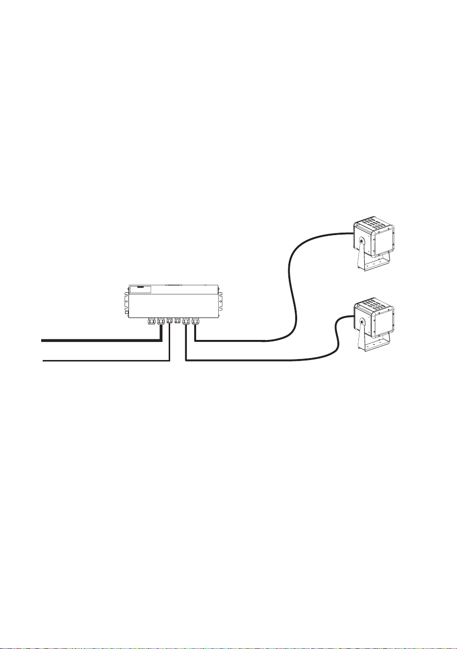
Minimum system layout
Figure 2 shows the most basic system layout possible.
In a minimum system:
• AC mains power is supplied to the Exterior 50 & 100 PSU via suitable
power cable.
• A data signal from a DMX controller is supplied to the PSU via DMX
cable.
• Combined 30 VDC power and DMX data from the PSU is supplied to
one to two Exterior 50 or Exterior 100 Luminaires via their supplied
luminaire cables.
Exterior 50 & 100 PSU
Data over DMX cable
Exterior 50 or 100
Luminaire
Exterior 50 or 100
Luminaire
AC mains power Luminaire cable (max. 13 m)
Luminaire cable (max. 13 m)
Unused cable glands
sealed with the correct
blanking plugs
Figure 2: Minimum system layout
Output = 2 x 100 W, 30 VDC
General information 19
Single group system layout
Figure 3 shows the layout of a single group of Exterior 100 Luminaires:
MAINS POWER
230VAC
Exterior 100 IP68 Exterior 100 IP68 Exterior 100 IP68 Exterior 100 IP68 Exterior 100 IP68
Exterior 50/100
Splitter
DMX512 CABLE
TO NEXT SECTION
Exterior 50/100 PSU
2x 100W / 30VDC
MAINS POWER
230VAC
DMX512 CABLE
< 50m< 50m
HYBRID CABLE HYBRID CABLE HYBRID CABLE HYBRID CABLE
FROM PREVIOUS
SECTION
Exterior 100 IP68 Exterior 100 IP68 Exterior 100 IP68 Exterior 100 IP68 Exterior 100 IP68
Exterior 50/100
Splitter
Exterior 50/100
Splitter
Exterior 50/100
Splitter
Exterior 50 IP68 Exterior 50 IP68Exterior 100 IP68 Exterior 50 IP68
< 13m
LUMINAIRE CABLE
< 13m
LUMINAIRE CABLE
Figure 3: Single group system layout
A larger version of this diagram is available on the Product Support pages for the Exterior 50/100 at www.martin.com
Products shown with optional light shields installed

20 Martin Professional™ Exterior 50 & 100™ system user manual
In a single group system:
• AC mains power is supplied to the Exterior 50 & 100 PSU via suitable
power cable.
• A DMX control data signal from a DMX controller is supplied to the PSU
via DMX cable.
• Combined 30 VDC power and DMX data from the PSU is supplied to
single daisy-chains of Splitters via hybrid (combined power and data)
cable.
• Combined power and data from each Splitter is supplied to Exterior 50
and/or 100 Luminaires via their supplied luminaire cables.
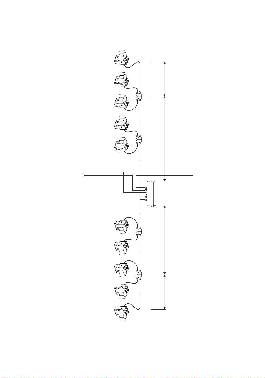
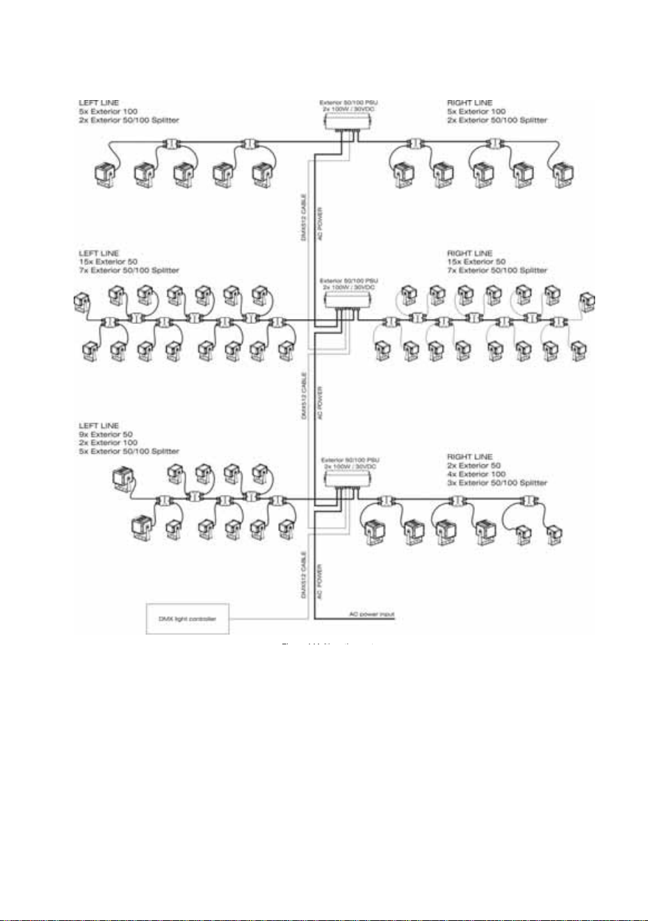
Multiple group system layout
Figure 4 on the next page shows a system layout with multiple groups.
In a multiple group system:
• AC mains power is supplied to the first Exterior 50 & 100 PSU and
relayed to following PSUs via suitable power cable.
• A DMX control data signal from a DMX controller is supplied to the first
PSU and relayed to following PSUs via DMX cable.
• Combined 30 VDC power and DMX data from each PSU is supplied to
single daisy-chains of Splitters via hybrid (combined power and data)
cable.
• Combined power and data from each Splitter is supplied to Exterior 50
and/or 100 Luminaires via their supplied luminaire cables.
General information 21
Fi 4M lti ti t
Figure 4: Multiple group system layout
A larger version of this diagram is available on the After-Sales/Product Support
pages for the Exterior 50 and 100 at www.martin.com
Max. permitted total current draw for all
interconnected devices = 16 amps

22 Martin Professional™ Exterior 50 & 100™ system user manual
Installation and connections: general
Warning! Read the ”Safety information” section starting on page 8
before carrying out work on the Exterior 50 & 100 system.
Warning! Luminaire cables may be installed in Luminaires and
serviced only by Martin™ and its authorized service agents.
Consult Martin™ if you have any doubts about the suitability and/or
safety of an installation.
See the system layout diagrams in the ”General information” section
starting on page 13 for an overview of how PSUs, Splitters and Luminaires
are linked. Note the following:
• Splitters can be used to link Luminaires to a PSU until the maximum
safe number of Luminaires per PSU output or per PSU is reached (see
”System layout limits” on page 16).
• The hybrid Splitter cables and luminaire cables used for internal system
connections carry both 30 VDC power and control data:
- Links from PSUs to Splitters, and links between Splitters, must use
the hybrid Splitter cable available from Martin™ in various lengths
(see ”Accessories” on page 79).
- Links to Luminaires must use the hybrid luminaire cable that is
supplied pre-installed in Luminaires. A 3 m (9.8 ft.) length is supplied.
If this is not long enough, please consult your Martin™ supplier for
assistance. Custom lengths up to a maximum safe limit of 13 m
(42.6 ft.) are available. Luminaire cables must be installed by Martin™
or its authorized agents.
General information 23
Installing a cable in a cable gland
All cable entries and exits in the Exterior 50 & 100 system use IP68 cable
glands to ensure that system components are sealed against water and
dust. When you install cable in PSUs and Splitters, you must follow the
instructions in this section carefully to ensure a correct seal.
To install a cable in a cable gland in a device in the Exterior 50 & 100
system:
1. If necessary, prepare the cable as described in the relevant sections
of this guide.
2. See Figure 5. Loosen – but do not remove – compression nut F on the
cable gland. Pass the cable through the gland D and cable entry C
until the cable jacket has passed completely through the cable gland
assembly. The cable should be a sliding fit in the gland.
3. Make wiring connections in the device as described in the relevant
sections of this guide.
4. Check that wiring is routed so that it is not stressed, then hold cable
entry C to prevent the cable gland assembly from rotating and tighten
compression nut F firmly enough to ensure a waterproof seal.
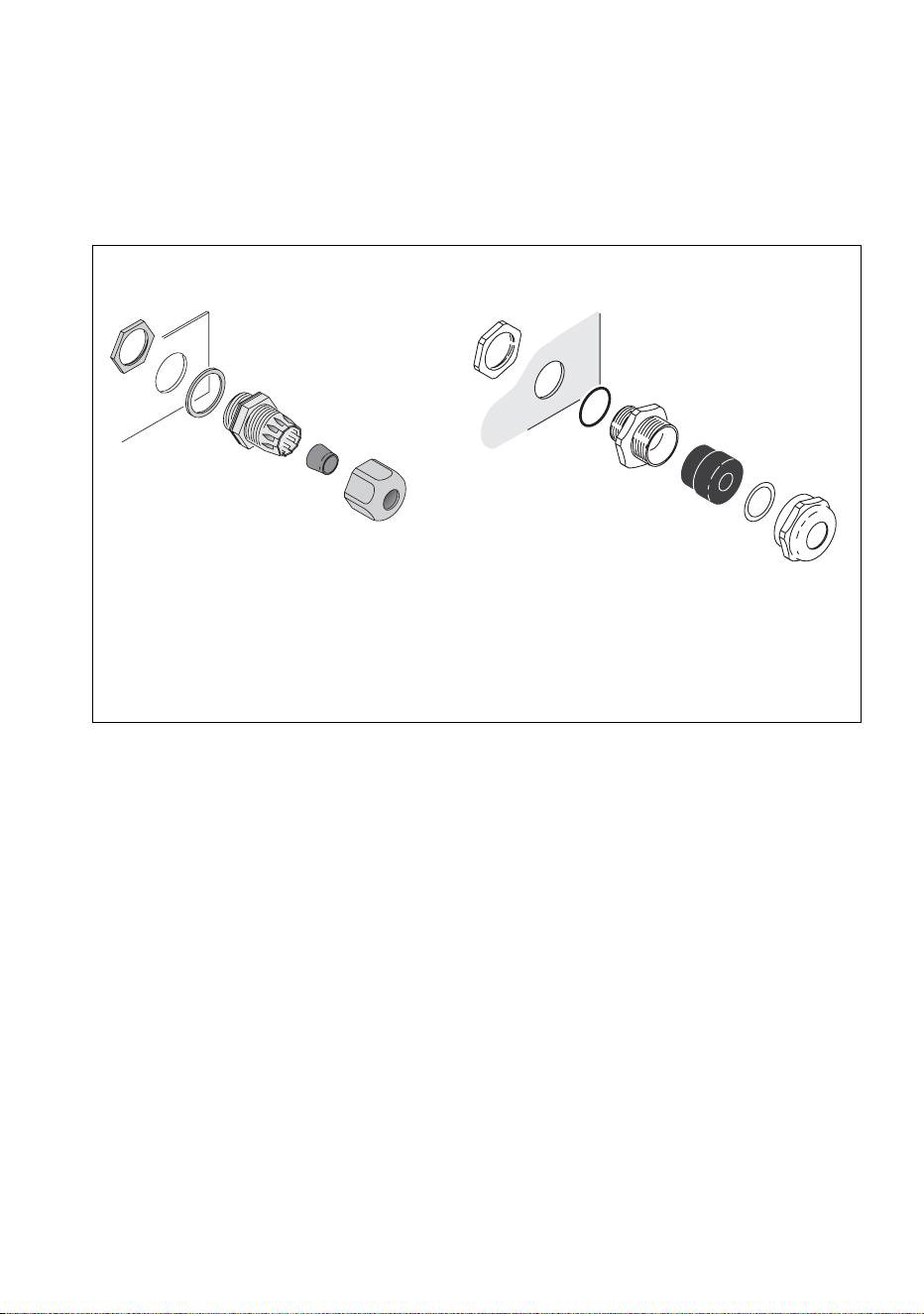
A
B
C
D
E
A – Locking nut
B – Sealing ring
C – Cable entry
D – Gland
E – Washer
F – Compression nut
F
Figure 5: Cable glands
A
B
C
D
F
Nylon cable gland Metal cable gland
24 Martin Professional™ Exterior 50 & 100™ system user manual
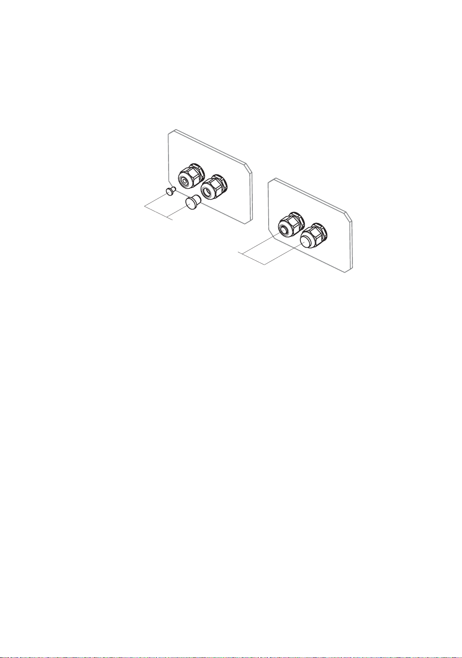
Installing a blanking plug in an unused cable gland
All unused cable glands in the Exterior 50 & 100 system must be sealed
with blanking plugs to prevent the entry of water and dust. Enough suitably
sized blanking plugs are supplied with PSUs and Splitters to cover all
possible situations.
To install a blanking plug in a cable gland:
1. See Figure 6. Check that you have the correctly-sized blanking plug
for the gland you need to seal (the correct blanking plug is a sliding fit
in the gland when the compression nut F is loosened).
2. See Figure 5 on page 23. Loosen – but do not remove – compression
nut F on the unused cable gland, insert a suitably-sized blanking plug
fully into the cable gland, then hold cable entry C to prevent the
assembly from rotating and tighten compression nut F firmly enough to
ensure a waterproof seal.
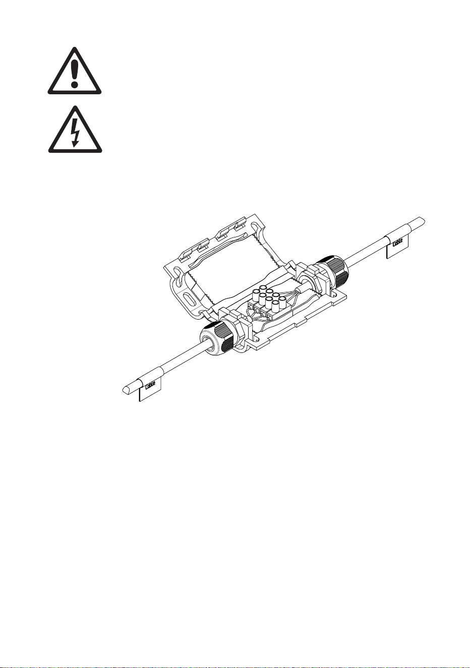
Using a luminaire cable connection box
If the cable supplied pre-installed on Luminaires is not long enough,
Martin™ can supply a gel-filled cable connection box that allows you to
make a gel-sealed waterproof connection to extend the cable.
The connection box kit available from Martin™ (P/N 90510230) includes
the box, two cable glands and a four-way terminal block. A 10 m (32 ft.)
luminaire cable extension kit (P/N 90510200) that includes the gel-filled
connection box kit is also available.
Figure 6: Cable gland blanking plugs
Blanking
plugs
General information 25
Use the gel-sealed luminaire cable connection box to extend
luminaire cables (the hybrid low-voltage/data cables supplied pre-
installed on Luminaires) only. Do not use it on any other type of
cable.
Ensure that cables that are connected using the box cannot be
pulled or strained.
Install cable glands and cable ties following the instructions
supplied with the box, or IP68 protection will not be obtained.
Do not exceed the maximum safe luminaire cable length of 13 m
(42.6 ft.) total from Splitter to Luminaire.
To connect cables using the cable connection box, follow the instructions
provided with the box. Note that you must:
• Use the connections box when extending Luminaire cables only. If any
other type of cable in the system is not long enough, replace it with a
complete length of suitable cable (see “Accessories” on page 79 for
cable available from Martin™).
• Ensure that cables connected using the box cannot be placed under
strain or tension.
• Break out the blanking sections in the connections box to prepare the
box to accept cable glands.
• Slide cable glands over cables before making wiring connections.
Figure 7: Luminaire cable connection box

26 Martin Professional™ Exterior 50 & 100™ system user manual
• Use the terminal block to connect the wires in one Luminaire cable to
the wires in the other cable that have the same color and markings (see
Table 1).
• When you have finished making connections, close the connections box
as directed in the supplied instructions, fastening it tightly with two cable
ties.
Wire / marking Function
Black 1 / red +30 VDC
Black 2 / blue -30 VDC
Black 3 / no mark Data +ve
Black 4 / yellow Data -ve
Table 1: Luminaire cable wiring identification

28 Martin Professional™ Exterior 50 & 100™ system user manual
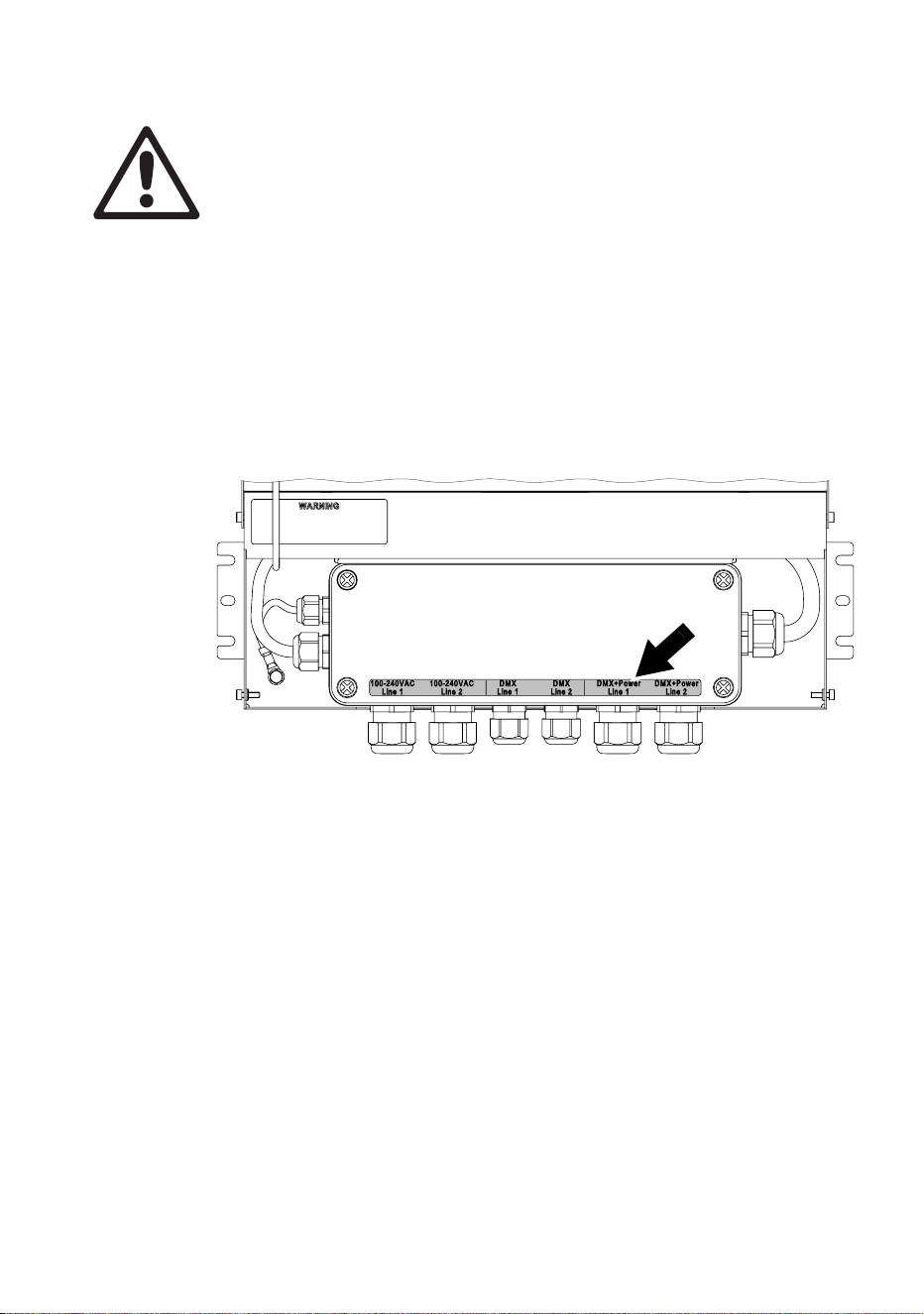
Warning! Install the PSU horizontally or with the cable outlets facing
downwards.
Figure 8 shows the EU model PSU, but mounting ears and dimensions
are the same for the US model PSU.
Supporting surfaces, fasteners and hardware must be capable of
supporting ten times the load they will bear when devices are installed and
suitable for the installation environment.
If you are not installing the PSU horizontally, install it with the cable glands
facing downwards to avoid water collecting at the cable entries.
Fasten the PSU securely to the mounting surface, ensuring space around
it so that you have access to cable glands and can open the PSU for
access to internal connections.
Installing Power Supply Units 29
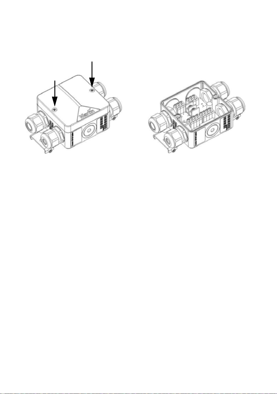
Connecting a PSU
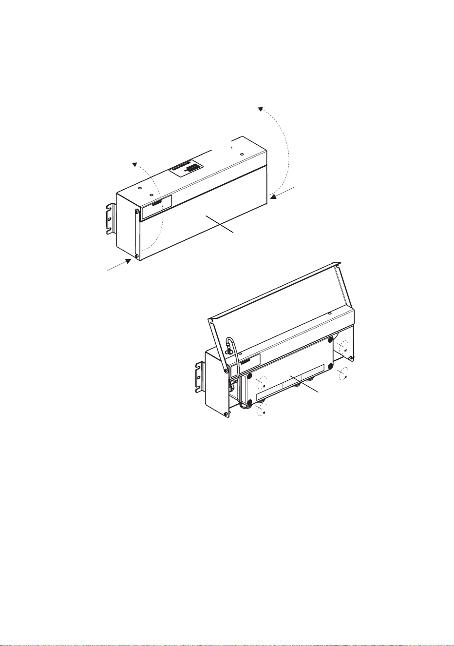
Internal access to a PSU
To access the terminals or check the system status indicator LEDs inside
a PSU, see Figure 9:
1. Check that the system is isolated from AC mains power and that
power cannot be reapplied during work on the system.
2. Remove the two screws (arrowed) from the outer cover and hinge the
cover open.
3. Remove the four screws from the plastic inner cover and lift the cover
off the box.
Figure 9: Internal access to PSU
Inner cover
Outer cover
Screw
Screw
(EU model PSU illustrated)

30 Martin Professional™ Exterior 50 & 100™ system user manual
AC mains power input
AC mains power operating range
The Exterior 50 & 100 PSU is fully auto-sensing and can be connected to
AC mains power as follows:
• The EU model PSU can be connected to mains power at 100-240 VAC
nominal at 50/60 Hz.
• The US model PSU can be connected to mains power at 100-240 VAC
nominal at 60 Hz.
Do not connect to power at any other voltage or AC frequency.
Power cable and plug
Cable that meets the power cable specifications listed on page 9 in the
”Protection from electric shock” section must be used to connect the
Exterior 50 & 100 PSU to an AC mains power source and to interconnect
PSUs if you create a power cable link.
The cable used to supply the system with power must be either hard-wired
to a building’s electrical installation, providing an easily accessible power
on/off switch close to the PSU, or fitted with a suitable grounding-type
(earthed) power plug that matches the local power outlets.
If you fit a power plug, follow the plug manufacturer’s instructions and
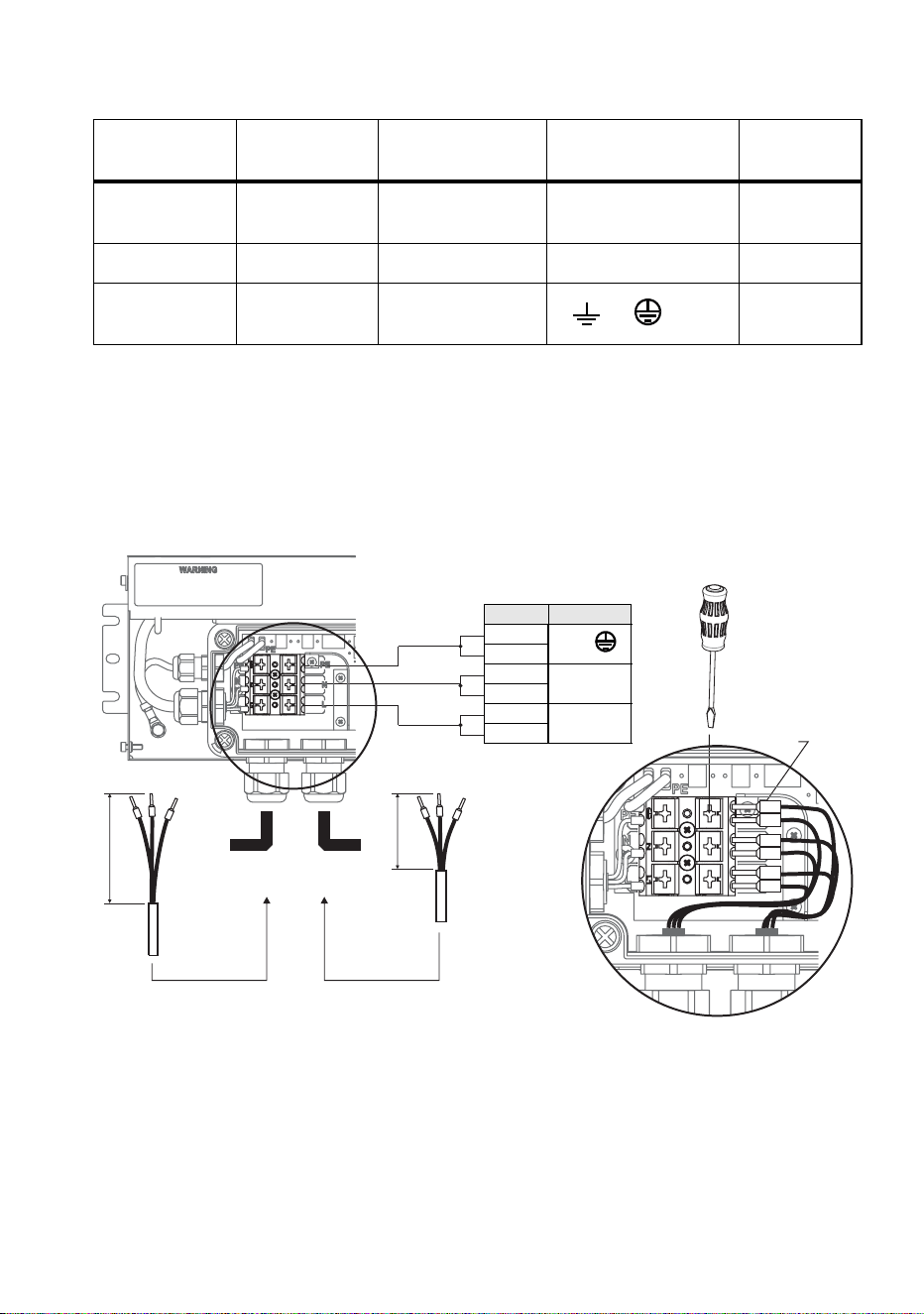
locally applicable wiring color code. Table 2 shows some pin and wire
color code identification schemes.
Installing Power Supply Units 31
Connecting a PSU to AC mains power
To connect the Exterior 50 & 100 PSU to AC mains power:
1. Check that the system is isolated from AC mains power and that
power cannot be reapplied during work on the system.
Wire
(US system)
Wire
(EU system)
Pin Marking
Screw
color
black brown live L
yellow or
brass
white blue neutral N silver
green yellow/green
ground
(protective earth)
or or PE
green
Table 2: Power plug pin and power cable wiring identification
Figure 10: AC mains power connections in PSU
Quick-lock
terminals
Power cable from
previous section
Power cable to
next section
Preparation of
power cable
Preparation of
power cable
90
50
AC power IN/OUT
PIN Function
6
PE
5
4
N
3
2
L
1
Press to
open

32 Martin Professional™ Exterior 50 & 100™ system user manual
2. Refer to Table 2 for common AC mains power cable wiring color
coding schemes.
3. The Exterior 50 & 100 PSU has quick-lock terminals for connecting
power cables. Each terminal accepts one input and one throughput
wire. Push down with a flat-blade screwdriver on a terminal as shown
in Figure 10 each time you need to insert or release wires. Check that
wires are fully inserted and held securely when you lift the screwdriver
away.
4. Obtain a suitable length of power input cable that meets the
specifications listed under ”Protection from electric shock” starting on
page 8.
5. See Figure 10. Prepare the power input cable for connection to the
PSU by stripping the last 90 mm (3.5 ins.) of the outer cable jacket.
Strip the last 10 mm (0.4 ins.) of the insulation from the ground/earth,
the neutral and the live wires, and install 10 mm (0.4 ins.) ferrules (I-
type end caps) on the ends of the wires.
6. See ”Installing a cable in a cable gland” on page 23. Pass the power
input cable through the cable gland marked 100-240 VAC Line 1 on
the PSU.
7. See Figure 10. Connect the wires from the power input cable to the
quick-lock terminals in the PSU as follows:
• Connect the ground/protective earth wire to the terminal marked PE.
• Connect the neutral wire to the terminal marked N.
• Connect the live wire to the terminal marked L.
8. Tighten the cable gland as described in ”Installing a cable in a cable
gland” on page 23.
9. If you are not continuing the AC mains power link from the PSU to
another PSU, see ”Installing a blanking plug in an unused cable gland”
on page 24. Install a blanking plug in the unused power cable gland
marked 100-240 VAC Line 2.
10. If you are continuing the AC mains power link to another PSU, follow
the instructions in the next section.

Installing Power Supply Units 33
Relaying AC mains power to other PSUs
Warning! The total current draw of all the Exterior 50 & 100 PSUs
that draw power from an AC power source in one interconnected
chain must not exceed 16 amps.
Exterior 50 & 100 PSUs can be interconnected in a chain so that they all
draw AC mains power via the first PSU, but the following points must be
respected:
• Connect only Exterior 50 & 100 PSU devices in the chain. Do not
connect any other device to power via an Exterior 50 & 100 PSU.
• The cable used for power throughput must meet the same
specifications as power input cable (see page 9).
To continue the AC mains power link from one Exterior 50 & 100 PSU to
another:
1. Obtain a suitable power cable (see above) to use for power
throughput.
2. See Figure 10. Prepare the power throughput cable for connection to
the first PSU by stripping the last 50 mm (2 ins.) of the outer cable
jacket, then stripping the last 10 mm (0.4 ins.) of the insulation from
the ground/earth, the neutral and the live wires. The use of ferrules (I-
type end caps) is recommended.
3. See ”Installing a cable in a cable gland” on page 23. Pass the power
throughput cable through the cable gland marked 100-240 VAC Line
2 on the PSU.
4. See Figure 10. Connect the wires from the power input cable to the
quick-lock terminals in the PSU as follows:
• Connect the ground/protective earth wire to the terminal marked PE.
• Connect the neutral wire to the terminal marked N.
• Connect the live wire to the terminal marked L.
5. Tighten the cable gland as described in ”Installing a cable in a cable
gland” on page 23.
6. Install the AC mains power throughput cable in the same terminals
used for AC mains power input in the first PSU using ”AC mains power
input” starting on page 30 as a guide. Use the cable gland marked
100-240 VAC Line 2 for power throughput cable exit from the PSU.
7. Run the power throughput cable to the next PSU and install it as if it
was a power input cable using ”AC mains power input” starting on
page 30 as a guide.
8. To continue interconnecting other PSUs in a chain, follow the
instructions above, but check that all the devices connected to all the
PSUs in the chain draw a total combined current that does not exceed
the safe maximum of 16 amps. To supply AC mains power to devices
34 Martin Professional™ Exterior 50 & 100™ system user manual
after the 16 amps maximum limit is reached, you must create a new
chain of PSUs that has its own connection to a building installation AC
mains power circuit.
Connecting a PSU to DMX control data
To connect the Exterior 50 & 100 PSU to DMX control data:
1. Check that the system is isolated from AC mains power and that
power cannot be reapplied during work on the system.
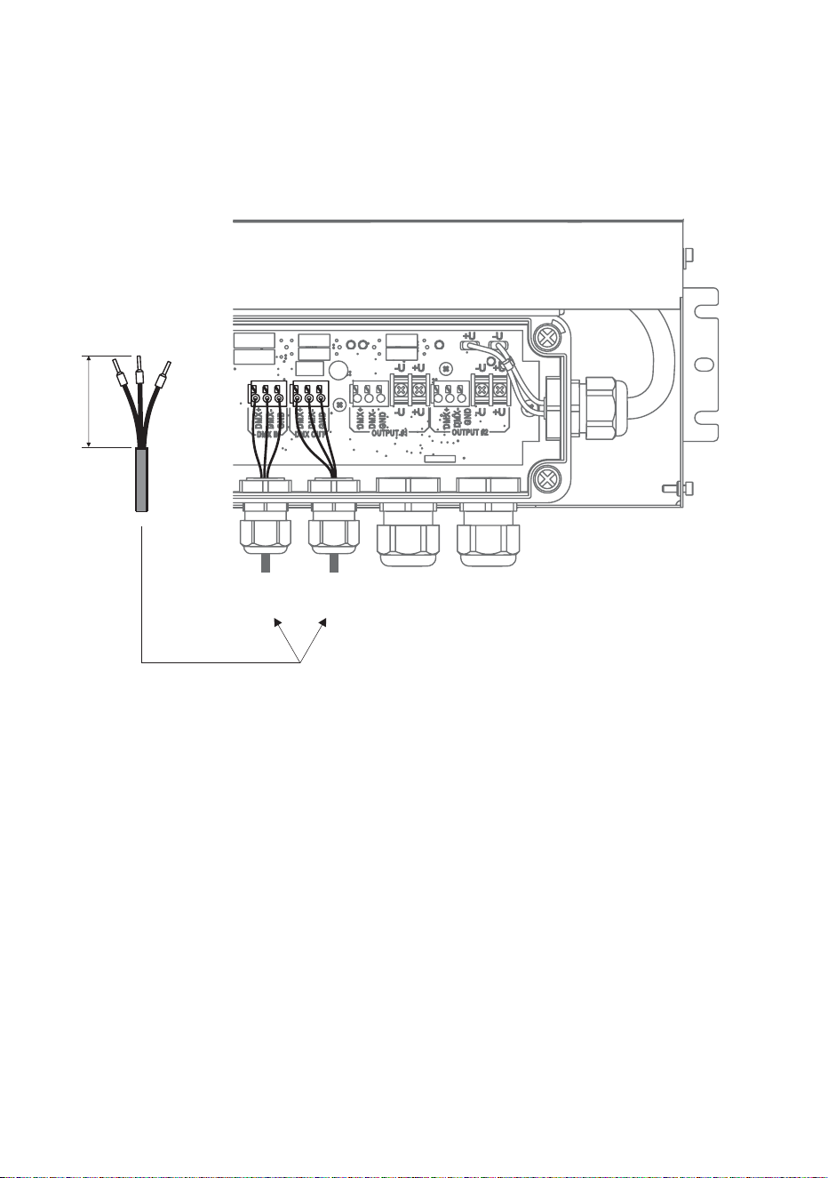
2. See Figure 11. Prepare the data input cable for connection to the PSU
by stripping the last 60 mm (2.4 ins.) of the outer cable jacket. Strip the
last 10 mm (0.4 ins.) of the data ground/common, the data +ve (hot)
and data -ve (cold) wires. The use of ferrules (I-type end caps) is
recommended.
Figure 11: Control data input connections in PSU
Preparation of DMX
data cable
60
DMX data
IN/OUT 1
DMX data
IN/OUT 2
Installing Power Supply Units 35
3. See ”Installing a cable in a cable gland” on page 23. Pass the data
input cable through the cable gland marked DMX Line 1 on the PSU.
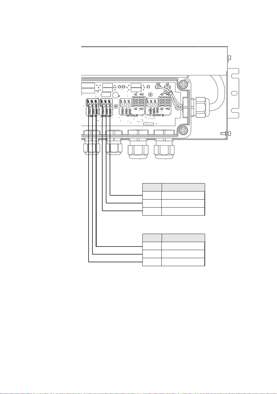
4. See Figure 12. Connect the wires from the DMX data input cable to
the terminals marked DMX IN in the PSU as follows:
• Connect the data shield/ground conductor to the terminal marked
GND.
• Connect the data +ve (hot) wire to the terminal marked DMX+.
• Connect the data -ve (cold) wire to the terminal marked DMX-.
Figure 12: DMX control data pinouts in PSU
DMX data IN/OUT 1
PIN Function
1 Data shield
2 Data -ve (cold)
3
Data +ve (hot
DMX data IN/OUT 2
PIN Function
1 Data shield
2 Data -ve (cold)
3
Data +ve (hot
36 Martin Professional™ Exterior 50 & 100™ system user manual
5. Tighten the cable gland as described in ”Installing a cable in a cable
gland” on page 23.
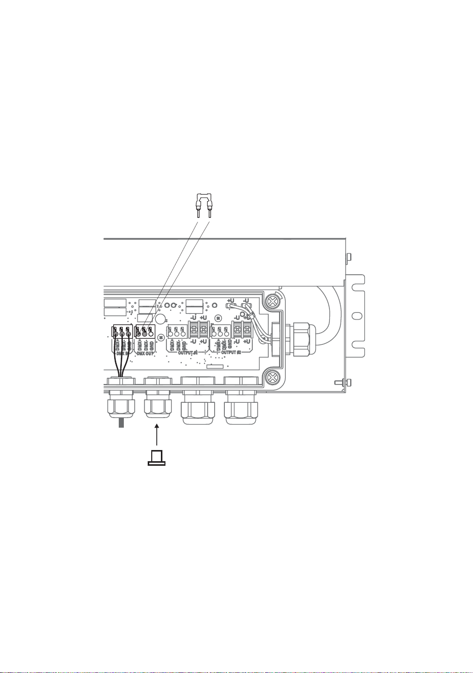
6. If you are not continuing the data link from the PSU to another PSU,
see Figure 13:
• Install the supplied DMX terminator in the unused DMX OUT
terminals so that it bridges the DMX+ and DMX+ terminals.
• Install a blanking plug in the unused cable gland marked DMX Line
2 (see ”Installing a blanking plug in an unused cable gland” on page
24).
7. If you are continuing the DMX data link to another PSU, follow the
instructions in the next section.
Figure 13: DMX termination in last PSU on link
DMX termination
Install DMX terminator
across DMX +ve and DMX -ve
Install plugs in all unused
cable glands

Installing Power Supply Units 37
Relaying DMX control data to other PSUs
Exterior 50 & 100 PSUs can be interconnected using DMX cable in a
chain to continue the DMX data link.
To extend the DMX data link from one Exterior 50 & 100 PSU to another:
1. Obtain a suitable length of DMX cable to use for data throughput.
2. See Figure 11. Prepare the DMX data throughput cable for connection
to the first PSU by stripping the last 60 mm (2.4 ins.) of the outer cable
jacket. Strip the last 10 mm (0.4 ins.) of the data ground/common, the
data +ve (hot) and data -ve (cold) wires. The use of ferrules (I-type
end caps) is recommended.
3. Install the DMX data throughput cable in the first PSU using
”Connecting a PSU to DMX control data” starting on page 34 as a
guide. Use the cable gland marked DMX Line 2 for data throughput
cable exit from the PSU.
4. Run the data throughput cable to the next PSU and install it as if it was
a DMX data input cable using ”Connecting a PSU to DMX control
data” starting on page 34 as a guide. Use the cable gland marked
DMX Line 1 for data throughput cable entry into the PSU.
5. If you need to continue interconnecting other PSUs in a daisy-chained
DMX link, use the instructions above as a guide.
38 Martin Professional™ Exterior 50 & 100™ system user manual
Connecting a PSU to a Splitter
To connect a hybrid Splitter cable to carry data and low-voltage DC power
from a PSU to a Splitter:
1. Obtain a suitable length of Martin hybrid Splitter cable (see cable
lengths available from Martin under “Accessories” on page 79).
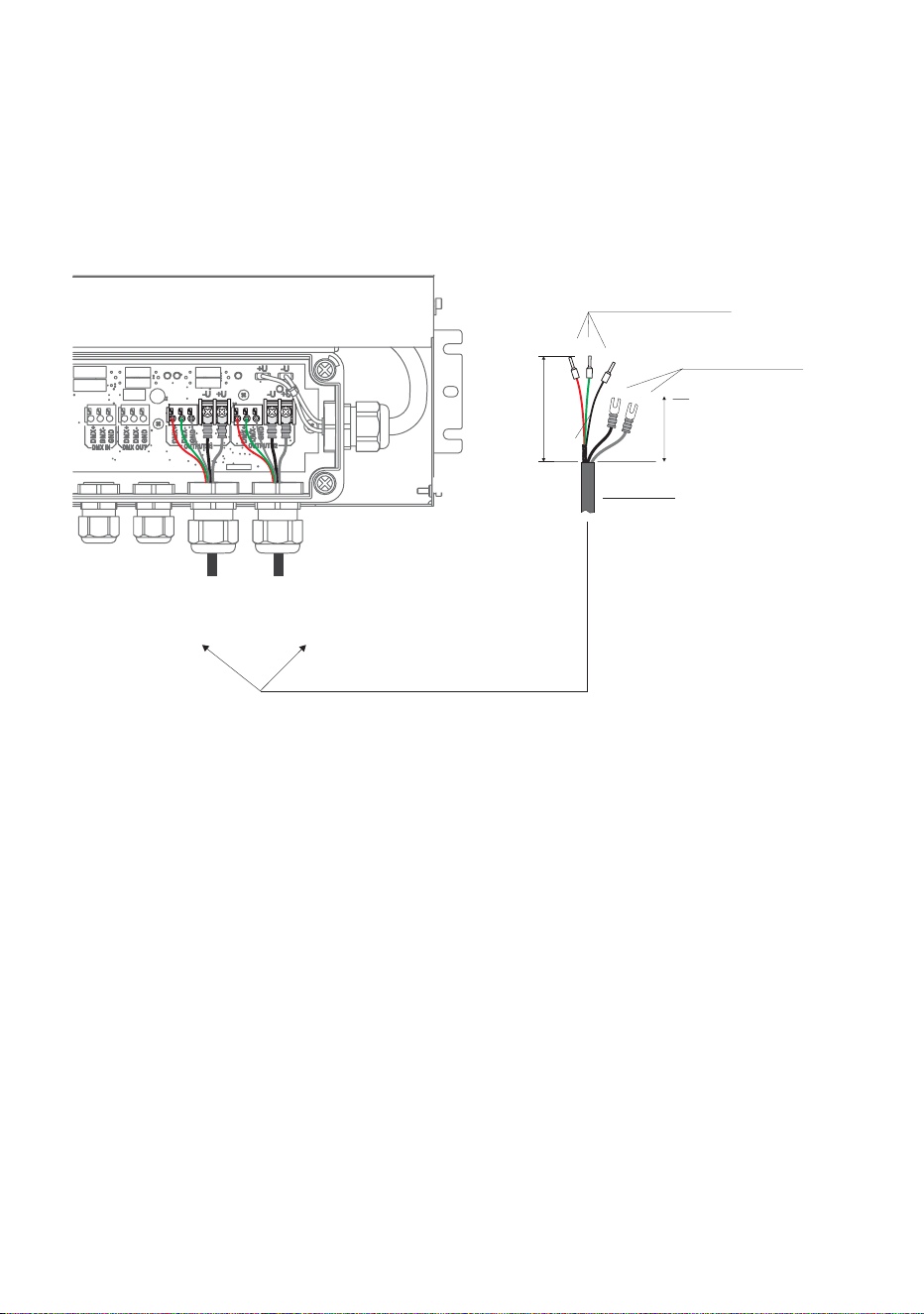
2. See Figure 14. Martin™ hybrid Splitter cables have ferrules (I-type end
caps) pre-installed on DMX control data wires and U-shaped end caps
pre-installed on 30 VDC wires. You can make a custom-length hybrid
Splitter cable by cutting the cable supplied by Martin™ to the required
length. If you do this, you must prepare custom cables for connection
inside the PSU. See Figure 14:
• strip 80 mm (3.1 ins.) of the outer cable jacket from the end of the
cable
• strip the last 10 mm (0.4 ins.) of the data ground/common, the data
+ve and data -ve wires and install ferrules (I-type end caps) on the
exposed conductors, then
• shorten the two 30 VDC wires, strip the last 10 mm (0.4 ins.) from
them and install U-shaped end caps that accept M3 screws onto the
exposed conductors so that each 30 VDC wire is 60 mm (2.4 ins.)
long including the end cap.
Figure 14: Hybrid link connections in PSU
Data connection:
I-type end caps (10 mm)
DC power connection:
U-type end caps for M3
screws
80
60
Hybrid
output 1
Hybrid
output 2
shield
Martin™ hybrid cable
Installing Power Supply Units 39
3. See ”Installing a cable in a cable gland” on page 23. Pass the hybrid
output cable through the cable gland marked DMX/RDM +Power #1
on the PSU.
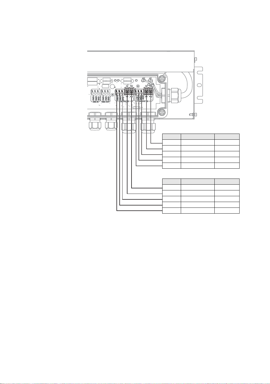
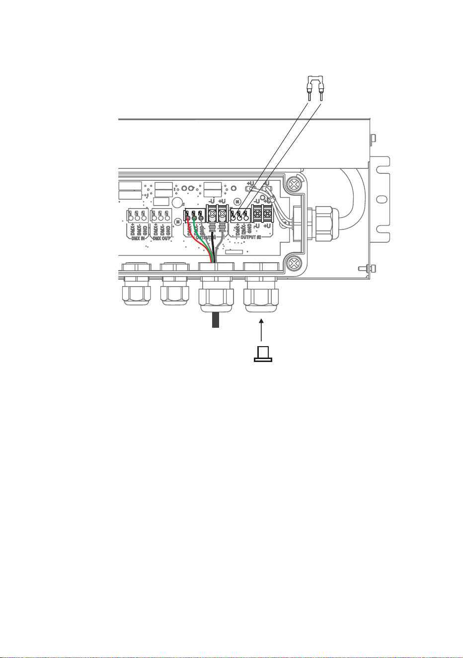
4. See Figure 15. Connect the wires from the hybrid Splitter cable to the
terminals marked OUTPUT #1 in the PSU as follows:
• Connect the braided copper and/or foil shield data ground/common
conductor to the terminal marked GND.
• Connect the red data +ve (hot) wire to the terminal marked DMX+.
• Connect the green data -ve (cold) wire to the terminal marked DMX-
• Connect the white 30 V +ve (hot) wire to the terminal marked +U.
• Connect the black 30 V -ve (cold) wire to the terminal marked -U.
5. Tighten the cable gland as described in ”Installing a cable in a cable
gland” on page 23.
Figure 15: Hybrid Splitter cable pinout in PSU
HYBRID SPLITTER CABLE PINOUT
Wire Function Terminal
White +30 VDC +U
Black -30 VDC -U
Shield Data shield DMX GND
Green Data -ve DMX-
Red Data +ve DMX+
HYBRID SPLITTER CABLE PINOUT
Wire Function Terminal
White +30 VDC +U
Black -30 VDC -U
Shield Data shield DMX GND
Green Data -ve DMX-
Red Data +ve DMX+
40 Martin Professional™ Exterior 50 & 100™ system user manual
6. If you are not going to create a second hybrid link from the PSU to a
Splitter or Luminaire, see Figure 16:
• Install the supplied DMX terminator in the unused OUTPUT #2
terminals so that it bridges the DMX+ and DMX+ terminals.
• Install a blanking plug in the unused cable gland marked
DMX/RDM +Power #2 (see ”Installing a blanking plug in an unused
cable gland” on page 24).
7. If you are going to create a second hybrid link from the PSU to a
Splitter or Luminaire, follow the above instructions for the second
hybrid cable, connecting the wires to the OUTPUT #2 terminals and
using the cable gland marked DMX/RDM +Power #2 for cable exit
from the PSU.
8. If you have finished making connections inside the PSU, follow the
instructions in ”Closing a CPU after internal access” on page 41.
Figure 16: Terminating an unused hybrid link in a PSU
DMX termination
Install DMX terminator
across DMX +ve and DMX -ve
Install plugs in all unused
cable glands
Hybrid
output 2
Installing Power Supply Units 41
Closing a CPU after internal access
Warning! When reinstalling the inner cover after internal access to
the CPU:
• Check that mating surfaces are clean and undamaged. If surfaces
are not in perfect condition, contact Martin™ for assistance.
• Reinstall the inner cover as it was originally installed, with the
connectors label over the connectors, or it will be impossible to
seal correctly.
• Reinstall all four inner cover screws securely.
After accessing the terminals and indicator LEDs inside a PSU:
1. See Figure 17. Check that all mating surfaces are in perfect condition
and reinstall the inner cover as it was originally installed, with the
connectors label (arrowed) over the connectors, tightening all four
inner cover screws securely.
2. See Figure 9 on page 29. Hinge the PSU outer cover closed and
reinstall its two screws securely.
Figure 17: PSU inner cover – correct reinstallation
42 Martin Professional™ Exterior 50 & 100™ system user manual
Installing Splitters
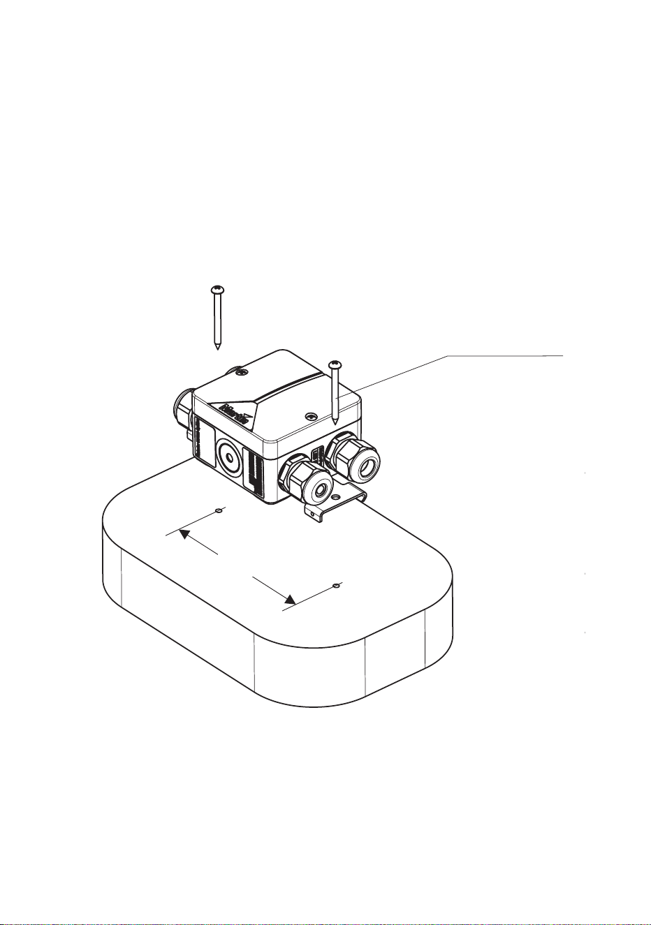
Physically installing a Splitter
Exterior 50 & 100 Splitters can be fastened to a flat surface (see Figure
18) or mounted on DIN rail (see Figure 19).
Supporting surfaces, fasteners and hardware must be capable of
supporting ten times the load they will bear when devices are installed.
Figure 18: Surface-mounting a Splitter
2 x M5 screws
115
Installing Splitters 43
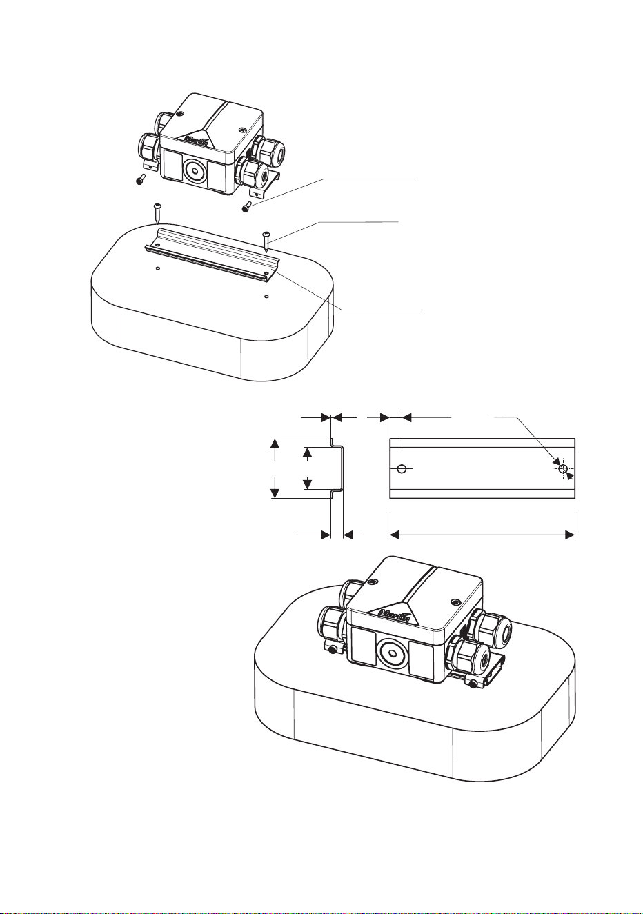
Figure 19: Mounting a Splitter on DIN rail
M3x10 screws (supplied)
4 mm screws (not supplied)
35 mm DIN rail (not supplied)
35 25
1 7 - 15 Ø5
7.5 130 - 150
44 Martin Professional™ Exterior 50 & 100™ system user manual
Connecting a Splitter
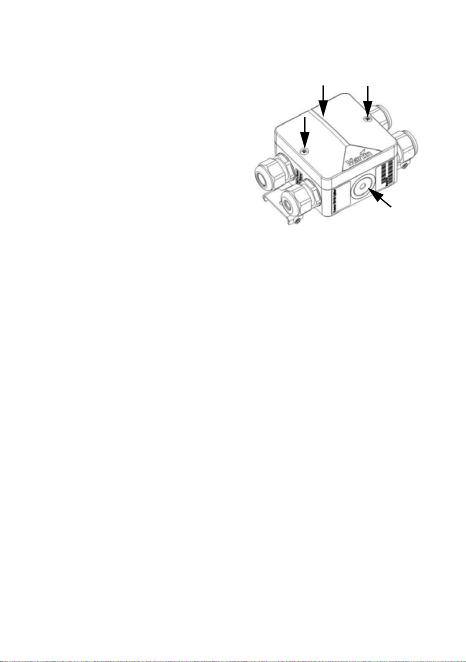
Internal access to a Splitter
For internal access to a Splitter:
1. Check that the system is isolated from AC mains power and that
power cannot be reapplied during work on the system.
2. See Figure 20. Remove the two screws A from the top cover and lift
the cover off the Splitter housing for access to the terminals and fuse.
3. After you have finished connecting and testing the Splitter, check that
mating surfaces are clean and undamaged and reinstall the top cover
and screws A securely, making sure that you do not trap any wires
under the top cover. Note that, if the Splitter is required to be fully
waterproof, you will need to fill it with IP68 sealant (see ”Filling a
Splitter with IP68 sealant” on page 57).
Figure 20: Internal access to Splitter
A
A
Installing Splitters 45
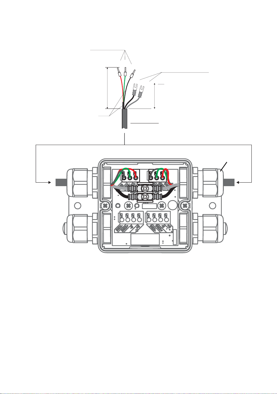
Connecting the hybrid link in a Splitter
To connect a hybrid Splitter cable carrying data and 30 VDC power to a
Splitter:
1. Check that the system is isolated from AC mains power and that
power cannot be reapplied during work on the system.
2. See Figure 21. Prepare a suitable length of Martin™ hybrid Splitter
cable for connection to the Splitter:
• strip 60 mm (2.4 ins.) of the outer cable jacket from the end of the
cable,
Figure 21: Hybrid cable connections in Splitter
Hybrid cable
gland
Data connection:
I-type end caps (10 mm)
DC power connection:
U-type end caps for M3
screws
40
60
shield
Martin™ hybrid cable

46 Martin Professional™ Exterior 50 & 100™ system user manual
• strip the last 10 mm (0.4 ins.) of the data ground/common, the data
+ve and data -ve wires and install ferrules (I-type end caps) on the
exposed conductors, then
• shorten the two 30 VDC wires, strip the last 10 mm (0.4 ins.) from
them and install U-shaped end caps that accept M3 screws onto the
exposed conductors so that each 30 VDC wire is 40 mm (1.6 ins.)
long including the end cap.
3. See ”Installing a cable in a cable gland” on page 23. Pass the hybrid
Splitter cable through one of the hybrid (larger cable diameter) cable
glands on the Splitter as shown in Figure 21.
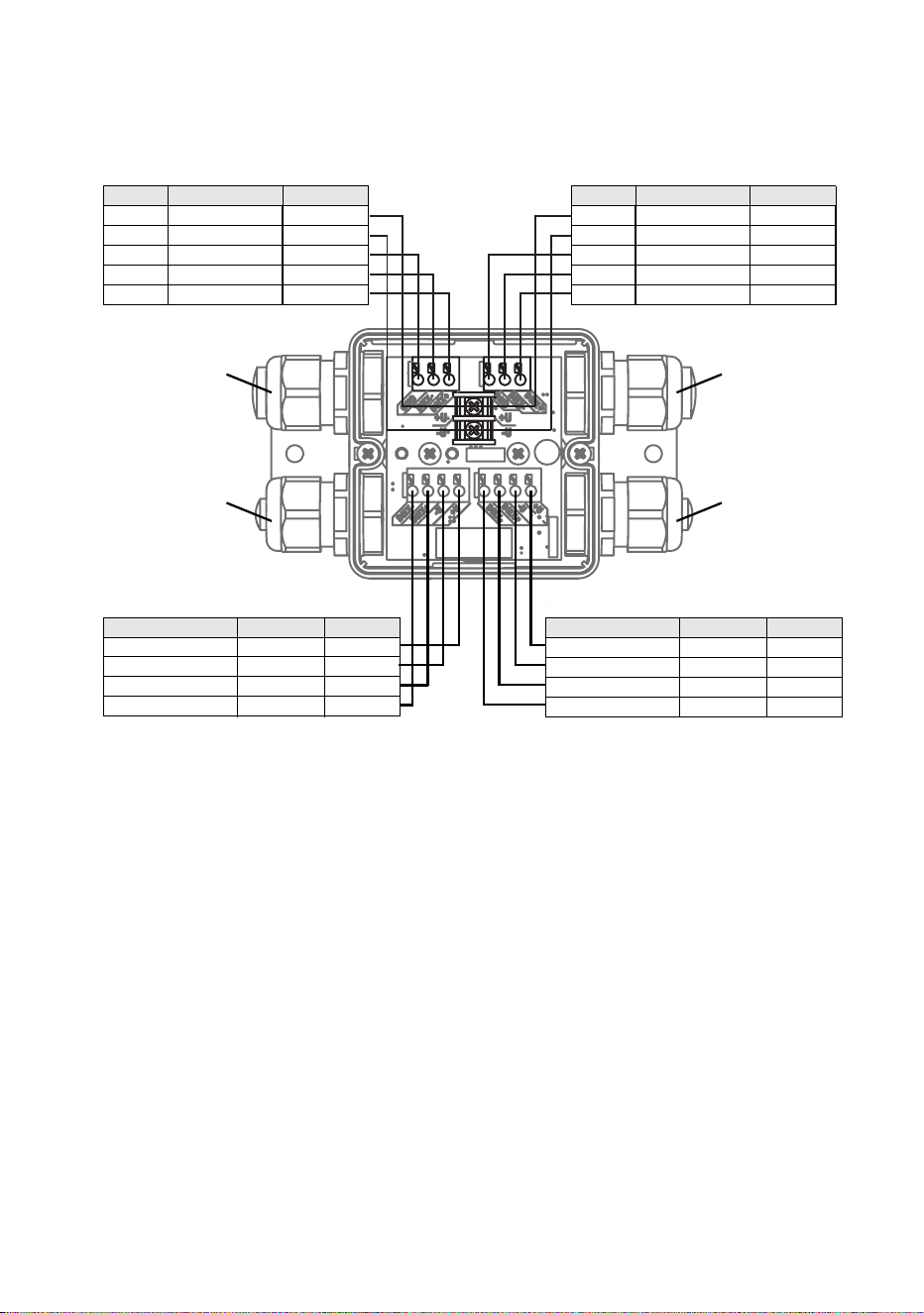
4. See Figure 22. Connect the wires from the hybrid Splitter cable to
either of the hybrid cable terminals in the Splitter as follows:
• Connect the braided copper and/or foil shield data ground/common
conductor to the terminal marked GND.
• Connect the red data +ve (hot) wire to the terminal marked DMX+.
• Connect the green data -ve (cold) wire to the terminal marked DMX-
• Connect the white 30 V +ve (hot) wire to the terminal marked +U.
• Connect the black 30 V -ve (cold) wire to the terminal marked -U.
Installing Splitters 47
5. Tighten the cable gland as described in ”Installing a cable in a cable
gland” on page 23.
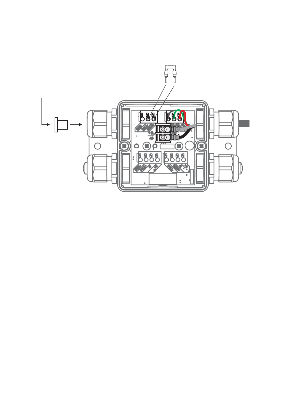
6. If you are not going to extend the hybrid link from the Splitter to
another Splitter, see Figure 23:
• Install the supplied DMX terminator in the unused DMX data
terminals as shown in Figure 23 so that it bridges the DMX+ and
DMX+ terminals.
• Install a blanking plug in the unused Splitter hybrid cable (larger
cable diameter) gland (see ”Installing a blanking plug in an unused
cable gland” on page 24).
7. If you are going to extend the hybrid link from the Splitter to another
Splitter, follow the above instructions for the Splitter hybrid output
HYBRID SPLITTER CABLE PINOUT
Wire Signal Terminal
White +30 VDC +U
Black -30 VDC -U
Shield Data shield DMX GND
Green Data -ve DMX-
Red Data +ve DMX+
HYBRID SPLITTER CABLE PINOUT
Wire Signal Terminal
White +30 VDC +U
Black -30 VDC -U
Shield Data shield DMX GND
Green Data -ve DMX-
Red Data +ve DMX+
LUMINAIRE CABLE PINOUT
Wire / marking Signal Terminal
Black 1 / red +30 VDC +U
Black 2 / blue -30 VDC -U
Black 3 / no mark Data -ve DMX-
Black 4 / yellow Data +ve DMX+
LUMINAIRE CABLE PINOUT
Wire / marking Signal Terminal
Black 1 / red +30 VDC +U
Black 2 / blue -30 VDC -U
Black 3 / no mark Data -ve DMX-
Black 4 / yellow Data +ve DMX+
Figure 22: Cable pinout in Splitter
HYBRID SPLITTER CABLE PINOUT
Wire Function Terminal
White +30 VDC +U
Black -30 VDC -U
Shield Data shield DMX GND
Green Data -ve DMX-
Red Data +ve DMX+
HYBRID SPLITTER CABLE PINOUT
Wire Function Terminal
White +30 VDC +U
Black -30 VDC -U
Shield Data shield DMX GND
Green Data -ve DMX-
Red Data +ve DMX+
LUMINAIRE CABLE PINOUT
Wire / marking Function Terminal
Black 1 / red +30 VDC +U
Black 2 / blue -30 VDC -U
Black 3 / no mark Data +ve DMX+
Black 4 / yellow Data -ve DMX-
LUMINAIRE CABLE PINOUT
Wire / marking Function Terminal
Black 1 / red +30 VDC +U
Black 2 / blue -30 VDC -U
Black 3 / no mark Data +ve DMX+
Black 4 / yellow Data -ve DMX-
Luminaire cable
gland
Hybrid Splitter
cable gland
Luminaire cable
gland
Hybrid Splitter
cable gland
48 Martin Professional™ Exterior 50 & 100™ system user manual
cable, connecting the wires to the unused hybrid cable in/out terminals
and passing the cable through the unused Splitter hybrid cable gland.
8. To connect Luminaires to a Splitter, see the next section of this guide.
Figure 23: Terminating hybrid link in Splitter
DMX termination
Install DMX terminator
across DMX +ve and DMX -ve
Install plugs in all
unused
cable glands

Installing Luminaires 49
Installing Luminaires
Using their supplied mounting brackets, Exterior 50 & 100 Luminaires can
be fastened to a flat surface, mounted on standard 35 mm top-hat section
DIN rail that is fastened to a flat surface, fastened to telescopic or fixed-
length mounting posts that are fastened to a flat surface, or fastened to a
ground stake that is embedded in the ground so that the stake will offer a
stable support.
Supporting surfaces, fasteners and hardware must be capable of
supporting ten times the load they will bear when devices are installed.
Physically installing Luminaires
Luminaires can be installed on a surface, on DIN rail or on a mounting
post (including a ground stake that is pushed into the ground to anchor it
securely)
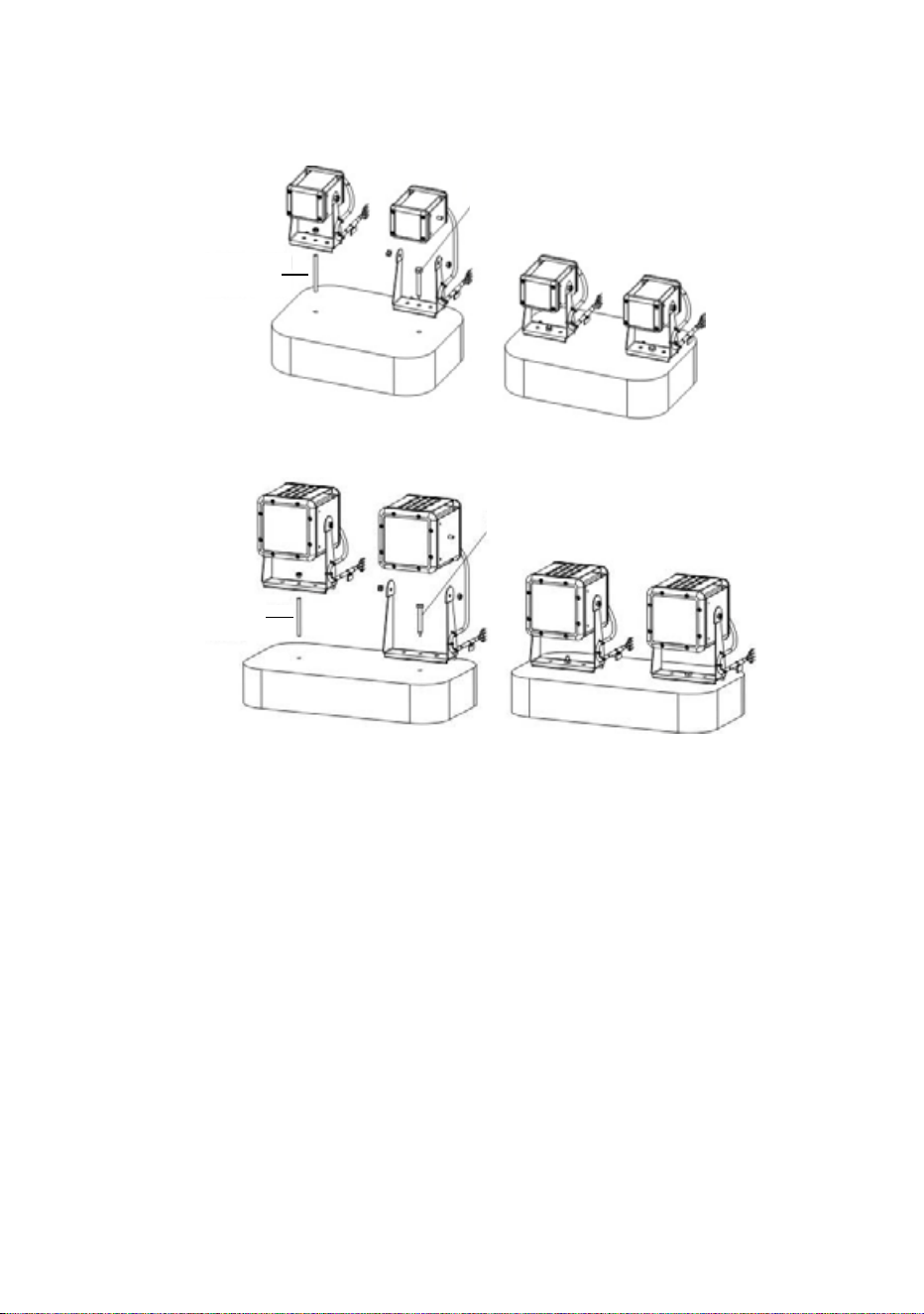
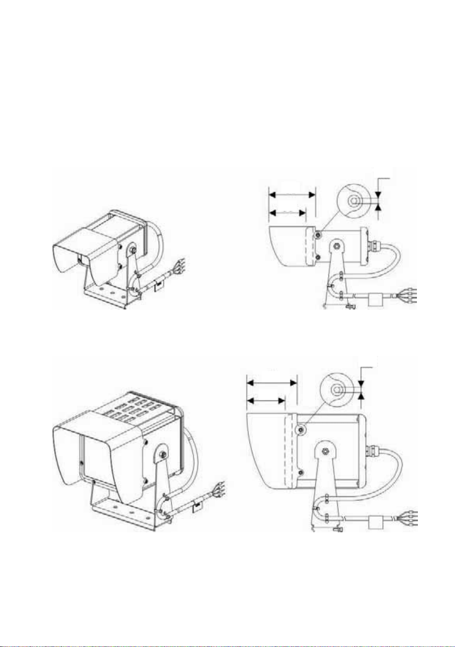
Fastening to a surface
An Exterior 50 or 100 Luminaire can be mounted on a flat, stable surface
in any orientation by fastening its mounting bracket to the surface. See
Figure 24.
To fasten to a surface:
1. Check that the surface is flat and stable, and that the surface and all
installation fasteners can support at least ten times the weight of all
devices and hardware they will bear.
2. Pass a steel M6 fastener that is suitable for the environment, grade
8.8 minimum, through the centre hole in the Luminaire mounting
bracket and tighten loosely at first.
3. Adjust the Luminaire for correct orientation and tighten the fastener.
50 Martin Professional™ Exterior 50 & 100™ system user manual
4. Check that the Luminaire is held securely and cannot fall.
Figure 24: Fastening to a surface
M5 threaded rod
Exterior 50
Exterior 100
M5 screw
M5 screw
M5 threaded rod
Installing Luminaires 51
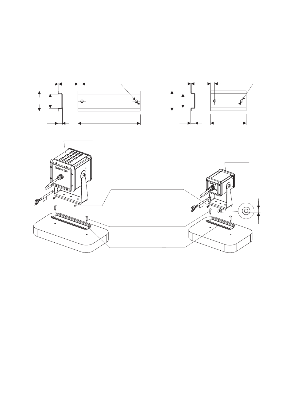
Fastening to DIN rail
Using the attachment options on their mounting brackets and the two
M3x10 Torx screws supplied with each Luminaire, Exterior 50 & 100
Luminaires can be mounted on standard 35 mm top-hat section DIN rail
that is fastened to a flat surface. See Figure 25.
To fasten an Exterior 50 or 100 mounting bracket to 35 mm DIN rail:
1. Check that the DIN rail is securely mounted on a flat surface that can
hold ten times the weight of all the hardware to be installed on it.
2. Hook the upper edge of the profile in the Luminaire mounting bracket
over the DIN rail and swing the mounting bracket down so that it
hangs flat against the DIN rail (you may need to loosen the two screws
in the mounting bracket base slightly for clearance).
3. Adjust for position, then tighten both screws in the mounting bracket
base securely behind the lower lip in the DIN rail.
4. Check that the Luminaire is held securely and cannot fall.
Figure 25: Fastening to DIN rail
35 25
1 7 - 15 Ø5
7.5 110 - 150
Ø5
35 25
1 7 - 15
7.5 75 - 100
Ø5
Exterior 100
Exterior 50
M3x10 screws (supplied)
4 mm screws (not supplied)
35 mm DIN rail (not supplied)
2.5
52 Martin Professional™ Exterior 50 & 100™ system user manual
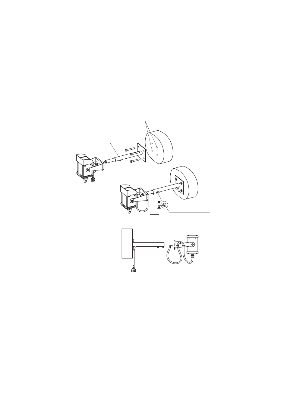
Installing on a mounting post or ground stake
Using their mounting bracket, Exterior 50 & 100 Luminaires can be
fastened onto the telescopic or standard (fixed-length) mounting posts or
ground stakes that are available as accessories from Martin™.
Mounting posts must be securely fastened to a flat surface. Ground stakes
must be securely embedded in the ground. All installation surfaces must
provide a stable support. Luminaires are fastened to mounting posts and
ground stakes using the same method.
To fasten a Luminaire mounting bracket to a mounting post:
1. Check that the mounting surface is flat and stable, and that it can
securely hold the weight of the Luminaire and cable.
2. See Figure 26. Fasten the mounting post securely to the mounting
surface using suitable steel grade 8.8 minimum fasteners. The
Luminaires will exert leverage on the end of mounting posts, so check
Figure 26: Fastening to a mounting post: Exterior 50
Fixing points 50 x 40
Adjustment screws
2.5
Exterior 50/100
Telescopic mounting post

Installing Luminaires 53
that fasteners and the anchoring method have sufficient strength to
hold the Luminaire plus an adequate safety margin for the location.
3. Fasten the Luminaire mounting bracket to the end of the post,
adjusting orientation before tightening the attachment nut.
4. Check that the Luminaire is held securely and cannot fall.
54 Martin Professional™ Exterior 50 & 100™ system user manual
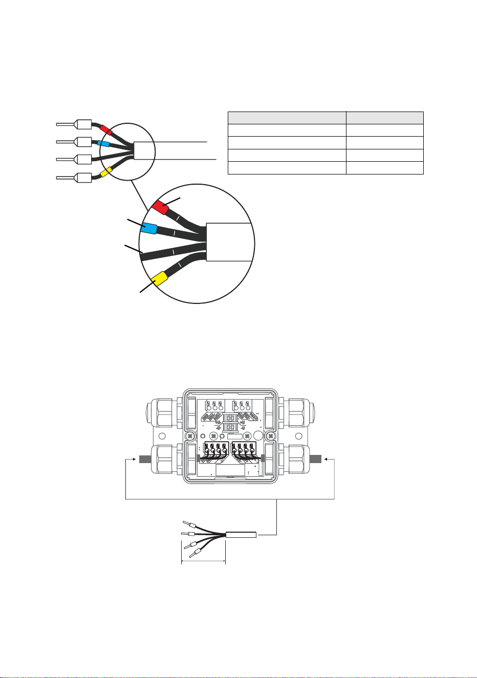
Connecting Luminaires
The conductors in the luminaire cable are identified in Figure 27 and cable
entry and layout are shown in Figure 28.
1
2
3
4
Figure 27: Luminaire cable wire markings
Red
Blue
No colored marking
Yellow
Wire / marking Function
Black 1 / red +30 VDC
Black 2 / blue -30 VDC
Black 3 / no mark Data +ve
Black 4 / yellow Data -ve
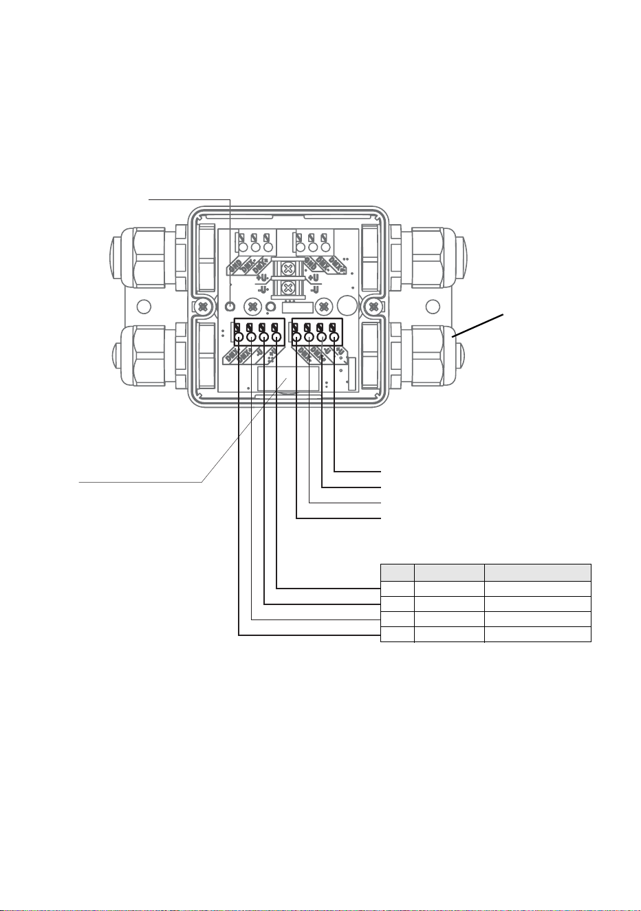
Figure 28: Luminaire cable connections in Splitter
50
Preparation of
Luminaire cable
Installing Luminaires 55
To connect a luminaire cable to a Splitter:
1. Check that the system is isolated from AC mains power and that
power cannot be reapplied during work on the system.
2. See ”Installing a cable in a cable gland” on page 23. Pass the
luminaire cable through either of the luminaire (smaller cable
diameter) cable glands on the Splitter (see Figure 29).
3. See Figure 29. Connect the wires from the luminaire cable to either of
the luminaire cable terminals in the Splitter as follows:
• Connect the 30 V +ve (hot) black wire marked 1 with the red ring to
the terminal marked +U.
• Connect the 30 V -ve (cold) black wire marked 2 with the blue ring
to the terminal marked -U
Figure 29: Luminaire cable pinout in Splitter
LUMINAIRE CABLE OUT #2
LUMINAIRE CABLE OUT #1
Luminaire cable
gland
Pin Signal Wire
1 +30 VDC Black 1 / red
2 -30 VDC Black 2 / blue
3 Data +ve Black 3 / no mark
4 Data -ve Black 4 / yellow
Luminaire output 2
Luminaire output 1
LED power
Fuse 2A T
for luminaire output

56 Martin Professional™ Exterior 50 & 100™ system user manual
• Connect the data +ve (hot) black wire marked 3 with no colored
ring to the terminal marked DMX+.
• Connect the data -ve (cold) black wire marked 4 with the yellow
ring to the terminal marked DMX-.
4. Tighten the cable gland as described in ”Installing a cable in a cable
gland” on page 23.
5. If you are going to connect another Luminaire to the Splitter, repeat the
above instructions for connecting Luminaires, installing the unused
luminaire (smaller diameter) cable gland on the luminaire cable and
connecting the wires in the luminaire cable to the unused luminaire
cable terminals.
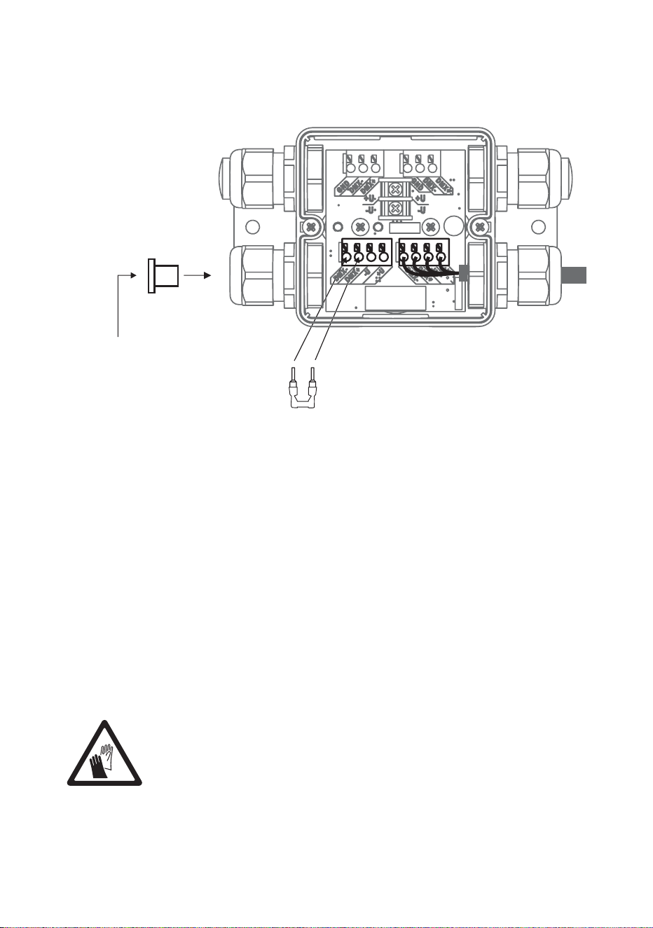
If you have finished making connections to the Splitter, see Figure 30:
• Install the supplied DMX terminator in the unused DMX data
terminals as shown in Figure 23 so that it bridges the DMX+ and
DMX+ terminals.
• Install the correct-sized blanking plug in any unused cable gland
(see ”Installing a blanking plug in an unused cable gland” on page
24).
• If the Splitter needs to be fully waterproof, fill it with the sealing
compound available from Martin™ (see ”Filling a Splitter with IP68
Installing Luminaires 57
sealant” on page 57) and re-install the cover on the Splitter (see
”Internal access to a Splitter” on page 44).
Filling a Splitter with IP68 sealant
If a Splitter needs to be protected to IP68, a sealing compound gel
available from Martin™ must be injected into the Splitter using a standard
caulking gun after all connections have been made.
The sealant is self-healing. This means that you can push a screwdriver
through it, for example, and it will reseal itself.
It is possible to remove the sealant after applying it if you need full access
to terminals again. If you remove the sealant, inject new sealant
afterwards to maintain IP68 protection.
Important! Avoid skin contact with the sealant. Use protective
gloves when working with the sealant.
Figure 30: DMX termination in unused luminaire cable output
DMX termination
Install DMX terminator
across DMX +ve and DMX -ve
Install plugs in all
unused
cable glands
58 Martin Professional™ Exterior 50 & 100™ system user manual
To apply sealant to a Splitter:
1. Check that all cables have
been connected and
connections tested.
2. See Figure 31. Place the
Splitter either horizontal
(with its cover C facing
upwards) or vertical (with
membrane B facing
upwards).
3. Either remove the two
screws A and lift the Splitter
cover off or use membrane
B for access, whichever will
let you inject the sealant
vertically downwards into the
Splitter.
4. Install the supplied mixer
nozzle on the sealant
cartridge and place the cartridge in a standard caulking gun.
5. The sealant in the cartridge is a thick liquid. Fill the Splitter completely
with sealant, allowing air to escape.
6. If you removed the Splitter cover, reinstall it, fastening both screws A.
7. Allow the sealant to cure for 24 hours before exposing the Splitter to
heavy splashing with water or immersion.
A
B
Figure 31: Access for sealant
injection
C
A
Installing Luminaires 59
Installing light shields
Light shields for Exterior 50 & 100 Luminaires are available as
accessories from Martin™. The shields reduce unwanted glare and guide
the light output at various beam angles. To install a shield on the front of a
Luminaire, see Figure 32. Fasten the four Allen screws that are supplied
with the shield through the shield and into the holes provided in the sides
of the Luminaire housing. Check that the screws are secure.
Figure 32: Exterior 50 and 100 Light Shields
Exterior 50
(Narrow Light Shield illustrated)
Exterior 100
(Narrow Light Shield illustrated)
66
53
2.5
71
54
2.5
60 Martin Professional™ Exterior 50 & 100™ system user manual
Checking and monitoring the
installation
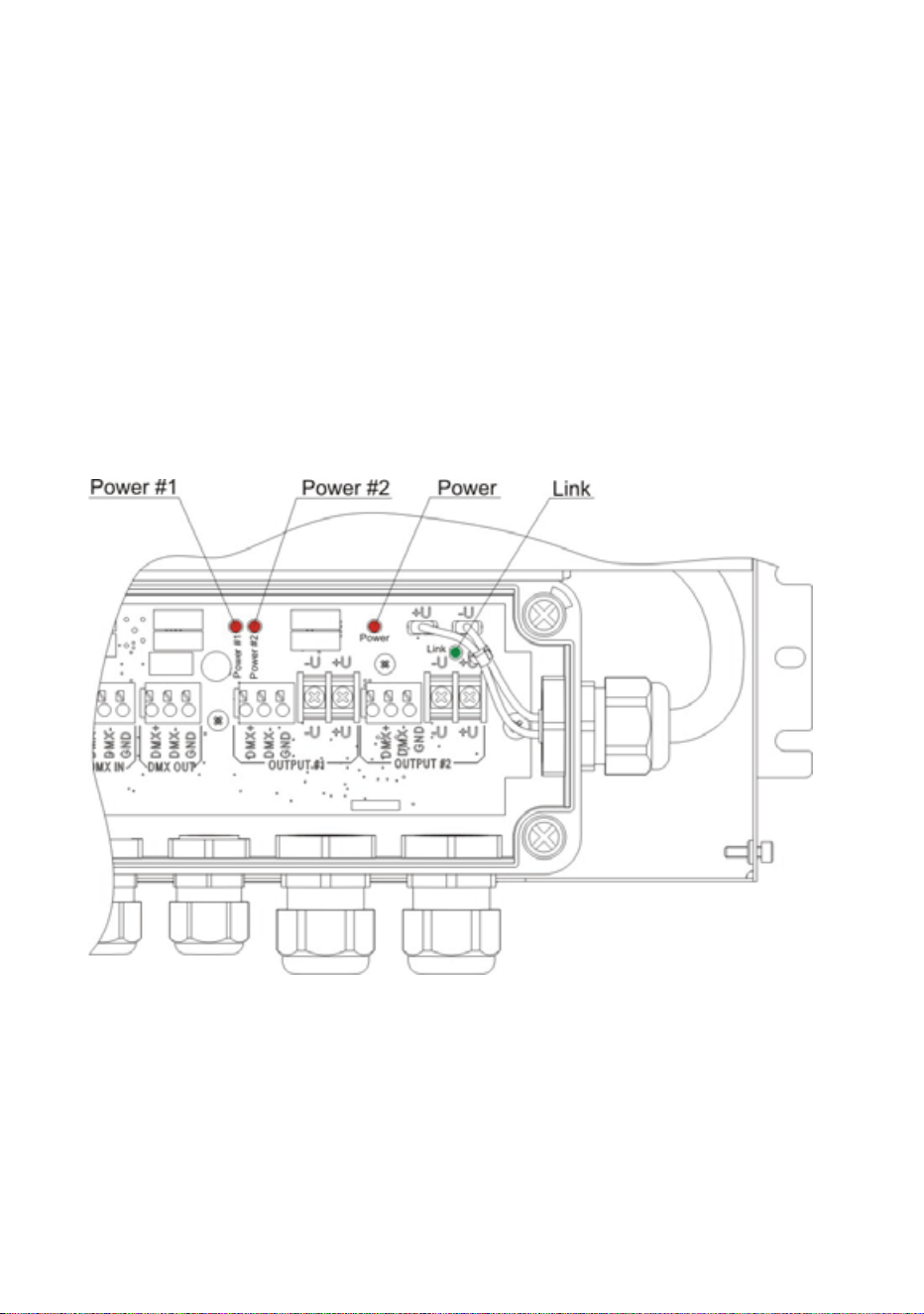
System status indicators in a PSU
See Figure 33. Four indicator LEDs inside a PSU give information about
system status:
• Power #1 lights red: indicates 30 V power transmission at output 1.
• Power #2 lights red: indicates 30 V power transmission at output 2.
• Power lights red: indicates that AC mains power is present at the input.
• Link flashes green: indicates data transmission at one or both of the
DMX data outputs.
For access to the indicator LEDs, follow the instructions in ”Internal
access to a PSU” on page 29 and ”Closing a CPU after internal access”
on page 41.
Figure 33: Status indicator LEDs in PSU
Checking and monitoring the installation 61
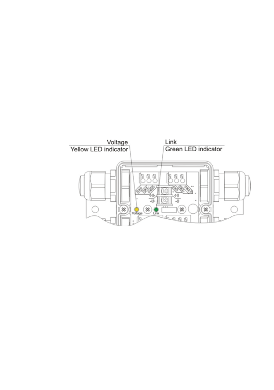
System status indicators in a Splitter
See Figure 34. Two indicator LEDs inside a Splitter give information about
system status:
•Link flashes green: indicates data transmission at one or both of the
DMX data outputs.
• Voltage lights constant yellow: indicates that the DC power received is
outside the 20-40 V acceptable range.
• Voltage flashes yellow: identifies the DC power voltage received.
- Long flashes indicate multiples of 10
- Short flashes indicate single digit
Example: Voltage LED gives two long flashes and nine short flashes –
DC voltage is 29 V.
For access to the indicator LEDs, follow the instructions in ”Internal
access to a Splitter” on page 44. If IP68 sealing compound has been
injected, the LEDs should still be visible through the gel sealant.
Figure 34: Status indicator LEDs in Splitter

62 Martin Professional™ Exterior 50 & 100™ system user manual
Setup
You can set Exterior 50 & 100 Luminaires to display a programmable
default scene and/or set them up for DMX control using the infrared
remote control unit available as an accessory from Martin™. The remote
control unit lets you communicate with one Luminaire at a time.
You can also set up Luminaires for DMX control and switch them between
calibrated and raw modes using an RDM (Remote Device Management)
compliant DMX controller such as the Martin M1™ console or the Martin
MPC™ Windows application. An RDM-compliant controller connected to
the data link lets you set up all the Luminaires on the link.
Setting up for DMX control
DMX Addressing
If DMX control of Exterior 50 & 100 Luminaires is required, they must be
set up to receive instructions from the DMX controller on a DMX channel
or group of DMX channels in the 512 channels available in their DMX
universe.
The DMX address, also known as the control address or start channel, is
the first of these channels. Each fixture uses this channel and the
channels immediately above it to receive instructions.
Exterior 50 & 100 Luminaires use 1, 3, or 4 DMX channels, depending on
model and raw/calibrated control mode. For example, if an RGBW
Luminaire’s DMX address is set to 1 and the Luminaire is in calibrated
(RGB) mode, it will use channels 1 - 3. Channel 4 will be available as the
DMX address for the next Luminaire.
If two or more identical Luminaires are set up with the same DMX address
(RGBW Luminaires must also be in the same control mode, either raw
RGBW or calibrated RGB), they will receive the same instructions and
behave identically. Setting up identical Luminaires with the same address
is an easy way to achieve synchronized action and can also be used as a
troubleshooting tool.
Calibrated and Raw modes
Luminaires can be operated in either Calibrated or Raw control mode.
Luminaires are supplied in Calibrated control mode, but they can be set
to Calibrated or Raw mode via RDM using an RDM-compliant controller
such as the Martin M-PC™ Windows application.

Setup 63
RGBW Luminaires
In RGBW Luminaires:
• Calibrated mode
gives slightly reduced LED power but, LEDs follow
factory-calibrated settings to give the best-matched color and white
output across multiple Luminaires.
In Calibrated mode, color output is controlled using three RGB DMX
channels. There is no DMX channel for white LED control. White output
is added to the calibrated RGB output automatically as required to
increase intensity and reduce color saturation.
• Raw mode
allows all LEDs to be operated to their absolute maximum
output regardless of color calibration issues. This means that hue,
saturation, intensity and white color temperature can vary slightly
between Luminaires.
In Raw mode, color output is controlled using four RGBW DMX
channels. The white LED control channel must be manually adjusted to
control intensity and color saturation in RGBW color mixing. Setting all
four channels to 100% gives maximum intensity white.
White Luminaires
In Cool White, Neutral White and Warm White Luminaires:
• Calibrated mode
gives slightly reduced LED power but sets LEDs to
their factory-calibrated output power to give the best-matched white
intensity across multiple Luminaires.
• Raw mode
allows all LEDs to be operated to their absolute maximum
output regardless of intensity issues. This means that white intensity
can vary slightly between Luminaires.
64 Martin Professional™ Exterior 50 & 100™ system user manual
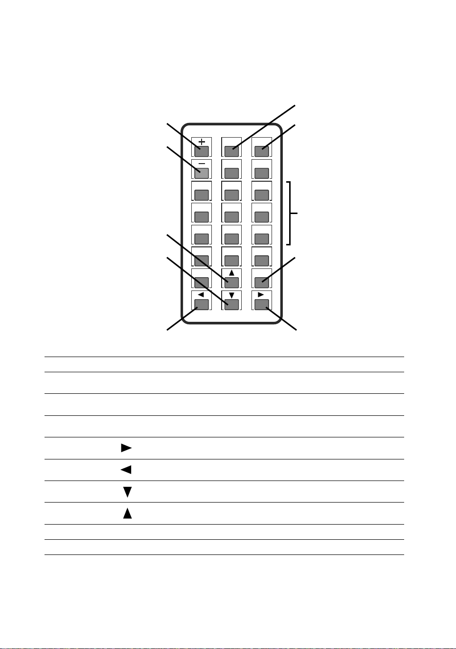
Setting up using the remote control
An IR (infrared) remote control unit for the Exterior 50 & 100 system is
available as an accessory from Martin™ (P/N 90510210).
1
4
7
0
Blank Esc
2
5
8
F2
F1
PP
TTM
Sign
F3
3
6
9
Figure 35: Remote control keypad
A
I
H
B
Numeric
keypad
G
F
E D
C
A
PP
Activates Remote Control mode in Luminaire
B
Sign
Stores configuration and exits Remote Control mode in
Luminaire
C
Esc
Exits Remote Control mode in Luminaire without storing
configuration
Numeric
keypad
1 - 0
Enters parameter values
D
Increase intensity of selected channel
(in Scene Setting mode)
E
Reduce intensity of selected channel
(in Scene Setting mode)
F
Sets all LEDs in Luminaire to zero intensity
(in Scene Setting mode)
G
Sets all LEDS in Luminaire to full intensity
(in Scene Setting mode)
H
–
Starts Scene Setting mode
I
+
Starts DMX Address Setting mode
Setup 65
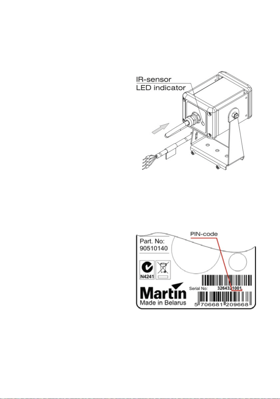
Setting a Luminaire to Remote Control mode
Before you can set up or program a Luminaire with the remote control,
you must set the Luminaire to Remote Control mode to allow
communication between the two devices:
1. See Figure 36.
Point the remote
control at the IR
sensor on the back
of the Luminaire.
2. See Figure 35.
Hold the
PP key
pressed in for five
seconds. When
communication is
established, the
status indicator
LED incorporated
in the sensor
begins to flash
green and the
Luminaire gives
three slow flashes
(yellow in RGBW
Luminaires).
3. See Figure 37.
Note the last four
digits of the
Luminaire’s serial
number labeled on
the fixture and
enter them using
the numeric
keypad on the
remote control.
The Luminaire
should flash each
time you press a
button.
4. Press the
Sign
key.
• If the four digits
have been entered correctly, the Luminaire flashes (green in RGBW
Luminaires) three times slowly to show that it has entered Remote
Figure 36: IR sensor and status indicator
LED
Figure 37: Luminaire serial number

66 Martin Professional™ Exterior 50 & 100™ system user manual
Control mode. The Luminaire automatically switches to DMX
Address Setting mode.
• If the four digits have not been entered correctly, the Luminaire
flashes (red in RGBW Luminaires) quickly and switches out of
Remote Control mode. Repeat the above procedure from Step 1.
Note that:
• The IR sensor status indicator LED flashes each time a button on the
remote control is pressed and the Luminaire accepts that entry.
• Only one parameter can be edited in one session of Remote Control
mode. To edit the next parameter, you must re-enter Remote Control
mode.
• If a Luminaire does not receive a remote control command for more
than 20 seconds, it exits Remote Control mode without saving the
configuration parameters.
• Any entered parameters are lost if you switch modes without storing
those parameters.
Setting a Luminaire’s DMX address
To set a Luminaire’s DMX address with the remote control unit:
1. Set the Luminaire to Remote Control mode (see previous section).
2. Press
+ to enter DMX Address Setting mode.
3. Enter the desired DMX address using the numeric keypad following
these principles:
• Each time you enter digits, the Luminaire responds with short LED
flashes.
• Enter the number in normal left-to-right order (first key pressed
enters first digit on left of address).
• Any digits on the left that are not entered are interpreted as zero (if
you only enter
5 or enter 05, your entry is interpreted as 005)
• Only the last three digits are accepted (if you enter
1234005, your
entry is interpreted as
005).
4. When you have entered the DMX address, press
Sign to store the
address in the Luminaire and exit DMX Address Setting Mode.
Programming a scene in a Luminaire
A ‘scene’ is a lighting effect or appearance (i.e. intensity, and in RGBW
Luminaires color).
Note that:
• Sixteen intensity levels are available in programmed scenes.
• If a DMX signal is present, it overrides the programmed scene.

Setup 67
• The factory default values are zero for all Luminaires.
To program a Luminaire’s default scene with the remote control unit:
1. Set the Luminaire to Remote Control mode (see previous section).
2. Press the
– key to enter Scene Setting mode. The Luminaire
responds with one short flash (blue in RGBW Luminaires) and the
LEDs switch to the last stored scene. LEDs flash each time the
Luminaire accepts an entry for the rest of this procedure.
3. In RGBW Luminaires, use digits
1 - 4 on the numeric keypad to select
the individual LEDs:
•
1 selects Red
• 2 selects Green
•
3 selects Blue
•
4 selects White
4. Set LED intensity as follows:
• Increases the intensity of the selected LEDs (in RGBW
Luminaires) or all LEDs
• Decreases the intensity of the selected LEDs (in RGBW
Luminaires) or all LEDs
• Sets all luminaires to zero intensity
• Sets all luminaires to full intensity
5. When you have programmed the scene, press
Sign to store the
scene in the Luminaire and exit Scene Setting Mode.
An Exterior 50 & 100 Luminaire will display its default scene each time it is
powered on, unless it receives a DMX signal.
Setting up via RDM using Martin M-PC™
The Exterior 50 & 100 system is compatible with RDM (Remote Device
Management). Using an RDM-compliant DMX controller such as the
Martin M-PC™ Windows application, you can communicate with the
Luminaires on the data link via RDM. You can retrieve Luminaire data,
and you can also:
• Set the DMX addresses of all the Luminaires on the link
• Set Luminaires to raw or calibrated modes.
To use Martin M-PC, connect a PC running this application to the data link
using the Martin USB Duo™ USB/DMX interface box.
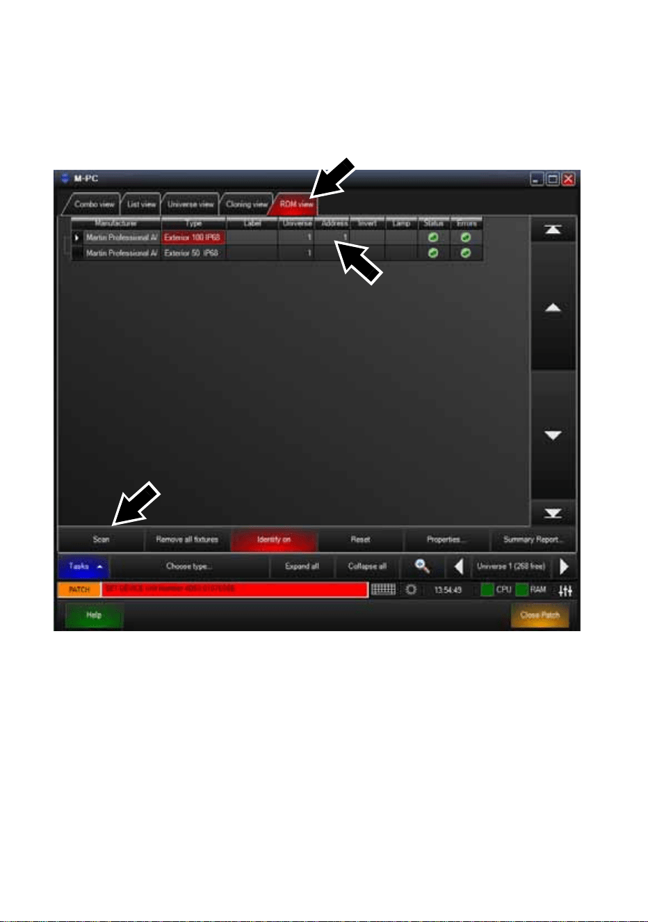
68 Martin Professional™ Exterior 50 & 100™ system user manual
Luminaire information and DMX address setting
See Figure 38. Opening the RDM View window in M-PC and clicking on
the Scan button (arrowed bottom left) gives a list of the RDM-compliant
devices on the data link (in this example, one Exterior 100 and one
Exterior 50 are present on the link, and both are set to DMX address 1).
To set Luminaires’ DMX addresses using M-PC, click in the Address box
for each Luminaire, enter the desired DMX address, then press the Enter
key on your PC keyboard to store the DMX address for that Luminaire.
Figure 38: M-PC RDM View
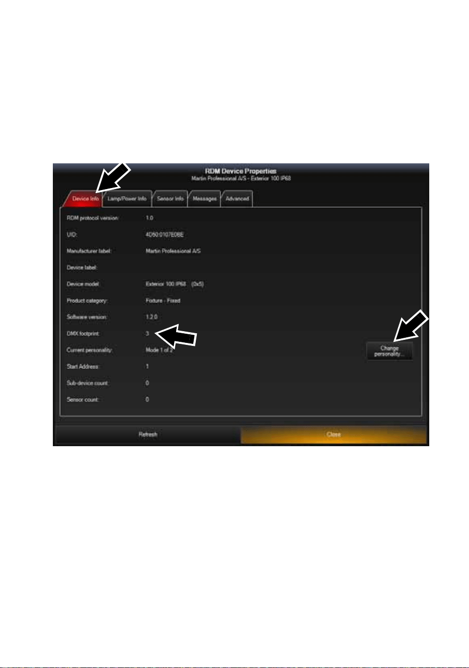
Setup 69
Configuring Luminaire settings
See Figure 39. Opening the Device Info window for a Luminaire on the
link calls up data for that Luminaire:
• Clicking on the Change personality... button (arrowed on right) in this
window lets you select Mode 1 (Calibrated RGB) or Mode 2 (Raw
RGBW) for the Luminaire.
• DMX footprint is updated with the number of DMX channels the
Luminaire uses in the mode you select.
Figure 39: M-PC Device Info view

70 Martin Professional™ Exterior 50 & 100™ system user manual
Operation
Exterior 50 & 100 Luminaires can be operated using a DMX controller or
set up to display a default scene that does not require DMX control.
If a Luminaire has been set up to display a default scene, it will display it
as soon as power is applied, but if DMX commands are sent to a
Luminaire, they override its default scene display.
Ambient temperatures
The Exterior 50 & 100 system – apart from the US model PSU for use in
North America – can be operated at ambient temperatures from 40° C
(40° F) to 45° C (113° F). The US model PSU for use in North America
can be operated at ambient temperatures from 40° C (40°F) to 40°C
(104° F). Do not operate devices outside their permitted temperature
range.
DMX control
The industry-standard DMX system allows remote control of an Exterior
50 & 100 installation over the DMX data link using a DMX controller or a
PC running DMX controller software such as the Martin M-PC™
application. If Luminaires have been set up with individual DMX
addresses, they can be controlled individually.
The section “DMX protocols” on page 73 gives details of the control
options available using DMX.
DMX channels in Raw and Calibrated modes
In RGBW Luminaires:
• RGBW control is available on four DMX channels when the Luminaire is
set to Raw mode.
• RGB control is available on three DMX channels when the Luminaire is
set to Calibrated mode.
When an RGBW Luminaire is set to Calibrated mode, white LED intensity
is added automatically to match the color saturation and intensity levels
set on the three RGB channels. Setting all three channels to 100% gives
maximum intensity white, with all LEDs – including white – at their
calibrated maximum.
In CW, NW and WW Luminaires, white LED intensity control is available
on one DMX channel in both Raw and Calibrated modes.
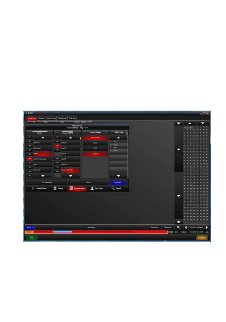
Operation 71
See also “Calibrated and Raw modes” on page 62.
Using Martin M-PC™ for DMX control
See Figure 40. If you do not already have M-PC™ profiles for the models
in the Exterior 50 & 100 series, you can create them in a few seconds.
Once you have profiles in the M-PC fixture library, you can control
Exterior 50 & 100 Luminaires via DMX using a Windows PC running M-
PC™ and connected to the data link via a Martin USB Duo™ USB/DMX
interface box
See the Martin M-PC™ user documentation for full details of using the M-
PC application.
Figure 40: M-PC Fixture Library and Fixture Settings
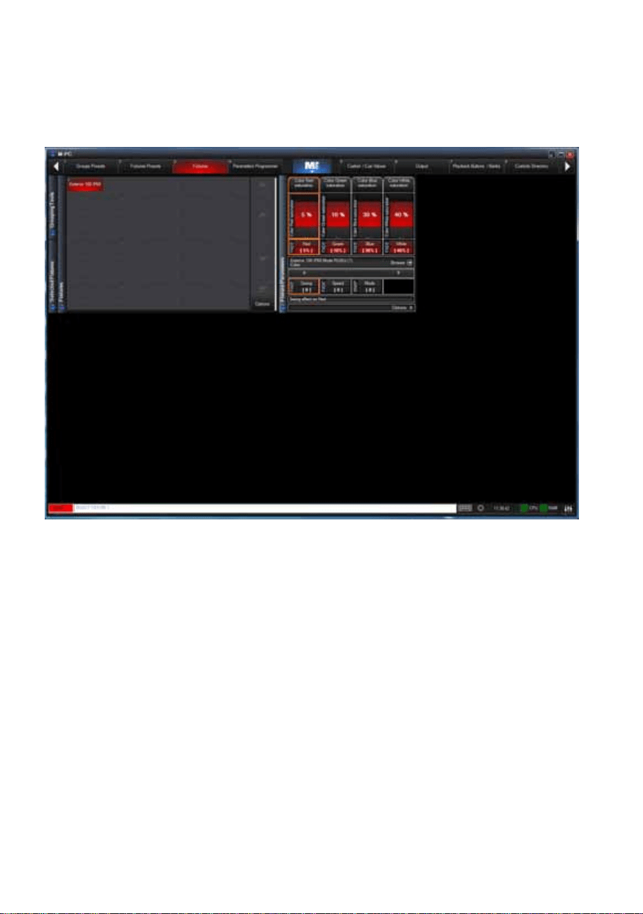
72 Martin Professional™ Exterior 50 & 100™ system user manual
Figure 41 shows the M-PC™ DMX control interface for an Exterior 100. In
this example, the Luminaire is in Raw (uncalibrated RGBW) mode. Red
output is set to 5%, Green is set to 10%, Blue is set to 30% and White is
set to 40%.
Figure 41: M-PC DMX control interface
DMX protocols 73
DMX protocols
RGBW Luminaires
Calibrated mode (calibrated RGB control)
Raw mode (uncalibrated RGBW control)
White (CW, NW and WW) Luminaires
Intensity control (Raw and Calibrated modes)
Start code = 0
Channel Value Percent Function
1
0 - 255 0 - 100
Red
Intensity 0 →100%
2
0 - 255 0 - 100
Green
Intensity 0
→100%
3
0 - 255 0 - 100
Blue
Intensity 0
→100%
Start code = 0
Channel Value Percent Function
1
0 - 255 0 - 100
Red
Intensity 0 →100%
2
0 - 255 0 - 100
Green
Intensity 0
→100%
3
0 - 255 0 - 100
Blue
Intensity 0 →100%
4
0 - 255 0 - 100
White
Intensity 0
→100%
Start code = 0
Channel Value Percent Function
1
0 - 255 0 - 100%
Single color
Intensity 0
→100%

74 Martin Professional™ Exterior 50 & 100™ system user manual
Service
Warning! There are no user-serviceable parts inside Luminaires.
Refer any service operation not described in this guide to Martin
Professional or its authorized service agents.
Installation, on-site service and maintenance can be provided worldwide
by the Martin Professional Global Service organization and its approved
agents, giving owners access to Martin’s expertise and product
knowledge in a partnership that will ensure the highest level of
performance throughout the product’s lifetime. Please contact your Martin
supplier for details.
The only service operation the user can carry out on the Exterior 50 & 100
system is occasional cleaning.
Cleaning
Do not use abrasive, caustic or solvent-based products for cleaning, as
they can encourage corrosion and cause surface damage.
To clean a device in the Exterior 50 & 100 system:
1. Disconnect the system from power and allow it to cool for at least 5
minutes.
2. Clean the outside of the device with a soft cloth slightly dampened in a
warm water/detergent solution.
Software installation
It may be necessary to upload new software (i.e. firmware) to an Exterior
50 & 100 Luminaire if you believe that the product has a software-related
fault or if you want to update to a newer version. Software updates are
available from the Martin website (http://www.martin.com) and can be
installed via the DMX data link with the following items:
• The Martin Software Uploader application, version 5.11 or later,
downloadable free of charge in the ‘DMX Tools’ package from the
Support area of the Martin website.
• The Luminaire’s main CPU software update file, downloadable free of
charge from the Support area of the Martin website (this file can be
downloaded automatically from within the Uploader application)
• A Martin DABS 1™ USB/DMX interface box and a Windows PC.

Service 75
Installing software
1. Connect a PC running the Martin Software Uploader application to a
Martin DABS 1™ interface box (included in P/N 90758090) and from
there to the Luminaire’s DMX data input or to a suitable point on the
DMX link. Software will be uploaded to that Luminaire and all
Luminaires of the same type that are powered on and connected via
the DMX link.
2. Upload the Luminaire software as described in the Uploader
application’s help file or user documentation.
3. Disconnect the uploader hardware and reconnect the Luminaire to the
DMX link.
4. Cycle power off and on. Check that the Luminaire resets correctly and
behaves normally. If it does not, cycle power off and on again and
check that the Luminaire now resets correctly and behaves normally.
If the problem persists, contact Martin™ for assistance.

76 Martin Professional™ Exterior 50 & 100™ system user manual
Troubleshooting
Problem Probable cause(s) Remedy
Luminaire is
completely dead.
No power to fixture. Check power and connections.
Fuse in Splitter blown.
Isolate system from power. Check fuse
and replace.
Fuse in PSU blown.
One or more
Luminaires responds
incorrectly to control or
does not respond at
all.
Fault on DMX link.
Inspect connections and cables. Correct
wrong or poor connections. Repair or
replace damaged cables.
Incorrect Luminaire
addressing.
Check that Luminaire is set to correct
DMX mode.
Check number of channels required by
Luminaire’s DMX mode and check
Luminaire addresses.
Luminaire defective.
Have faulty Luminaire serviced by Martin
service technician.
Other device on DMX link
defective.
Bypass devices on DMX link until faulty
device has been identified.
Have faulty device tested and serviced
by Martin service technician or device
supplier.
Luminaires cut out
intermittently.
PSU is too hot.
Ensure free airflow around PSU.
Clean PSU.
Check that ambient temperature does
not exceed maximum permitted level.
Contact Martin for service.
Table 3: Troubleshooting

Specifications 77
Specifications
Physical
Exterior 50 Luminaire
Length . . . . . . . . . . . . . . . . . . . . . 130 mm (5.1 in.) including clearance for cable
Width . . . . . . . . . . . 87 mm (3.4 in.) including mounting/tilt adjustment fasteners
Height . . . . . . . . . . . . . . . . . . . . . . . 117 mm (4.6 in.) including mounting bracket
Weight . . . . . . . . . . . . . . . . . . . . . . . 660 g (23.3 oz.) including mounting bracket
Exterior 100 Luminaire
Length . . . . . . . . . . . . . . . . . . . . . 165 mm (6.5 in.) including clearance for cable
Width . . . . . . . . . . 127 mm (5.0 in.) including mounting/tilt adjustment fasteners
Height . . . . . . . . . . . . . . . . . . . . . . . 166 mm (6.5 in.) including mounting bracket
Weight . . . . . . . . . . . . . . . . . . . . . . . 1.4 kg (3.1 lbs.) including mounting bracket
Exterior 50/100 Splitter
Length . . . . . . . . . . . . . . . . . . . . . . . . . . 133 mm (5.2 in.) including cable glands
Width . . . . . . . . . . . . . . . . . . . . . . . . . . . . . . . . . . . . . . . . . . . . . . 80 mm (3.1 in.)
Height . . . . . . . . . . . . . . . . . . . . . . . . . . . . . . . . . . . . . . . . . . . . . . 59 mm (2.3 in.)
Weight . . . . . . . . . . . . . . . . . . . . . . . . . . . . . . . . . . . . . . . . . . . . . . 230 g (8.1 oz.)
Exterior 50/100 Power Supply Unit, EU model
Length . . . . . . . . . . . . . . . . . . . . . . . . . . . . . . . . . . . . . . . . . . . 355 mm (14.0 in.)
Width . . . . . . . . . . . . . . . . . . . . . . . . . . . 146 mm (5.7 in.) including cable glands
Height . . . . . . . . . . . . . . . . . . . . . . . . . . . . . . . . . . . . . . . . . . . . . . 83 mm (3.3 in.)
Weight . . . . . . . . . . . . . . . . . . . . . . . . . . . . . . . . . . . . . . . . . . . . . 2.8 kg (6.2 lbs.)
Exterior 50/100 Power Supply Unit, US model
Length . . . . . . . . . . . . . . . . . . . . . . . . . . . . . . . . . . . . . . . . . . . 355 mm (14.0 in.)
Width . . . . . . . . . . . . . . . . . . . . . . . . . . . 186 mm (7.4 in.) including cable glands
Height . . . . . . . . . . . . . . . . . . . . . . . . . . . . . . . . . . . . . . . . . . . . . . 90 mm (3.6 in.)
Weight . . . . . . . . . . . . . . . . . . . . . . . . . . . . . . . . . . . . . . . . . . . . . 3.4 kg (7.5 lbs.)
Exterior 50/100 Infrared Remote Control Unit
Length . . . . . . . . . . . . . . . . . . . . . . . . . . . . . . . . . . . . . . . . . . . . 145 mm (5.7 in.)
Width . . . . . . . . . . . . . . . . . . . . . . . . . . . . . . . . . . . . . . . . . . . . . . . . 50 mm (2 in.)
Height . . . . . . . . . . . . . . . . . . . . . . . . . . . . . . . . . . . . . . . . . . . . . . . . 23 mm (1 in.)
Weight . . . . . . . . . . . . . . . . . . . . . . . . . . . . . . . . . . . . . . . . . . . . . . 100 g (3.5 oz.)
Dynamic Effects
Color mixing . . . . . . . . . . . . . . . . . . . . . . . . . . . . . . . . . . RGBW (RGBW models)
Intensity . . . . . . . . . . . . . . . . . . . . . . . . . . . . . . . . . . . . . . . 0 - 100% (all models)
Optics
Light source . . . . . . . . . . . . . . . . . . . . . . . . . . . . Cree MC-E high-power emitters
Color temperature (CW model) . . . . . . . . . . . . . . . . . . . . . . . . . . . . . . . . .6500 K
Color temperature (NW model) . . . . . . . . . . . . . . . . . . . . . . . . . . . . . . . . .4000 K
Color temperature (WW model) . . . . . . . . . . . . . . . . . . . . . . . . . . . . . . . . .2700 K
Minimum LED lifetime . . . . . . . . . . . . .50 000 hours (to >70% luminous output)*
*Manufacturer´s figure obtained under manufacturer´s test conditions

78 Martin Professional™ Exterior 50 & 100™ system user manual
Control and Programming
Control options . . . . . . . . . . . . . . . . . . . . . . . DMX, programmable default scene
Color control modes . . . . . . . . . . Calibrated RGB, Raw RGBW (RGBW models)
Control modes . . . . . . . . . . . . . . . . . . . . . . . . . .Calibrated and Raw (all models)
DMX channels . . . . . . . . . . .1 (CW, NW and WW models), 3/4 (RGBW models)
Setting and addressing . . . . . . .IR remote control unit, RDM-compliant controller
Dimming resolution. . . . . . . . . . . . . . . . . . . . . . . . . . . . . . . . . . . . 14-bit (internal)
DMX compliance. . . . . . . . . . . . . . . . . . . . . . . . . . . . . . . . . . . . USITT DMX512-A
RDM compliance . . . . . . . . . . . . . . . . . . . . . . . . . . . . . . . . . . .ANSI/ESTA E1.20
Receiver . . . . . . . . . . . . . . . . . . . . . . . . . . . . . . . . . . . . . . . . . . . . . . . . . . RS-485
Firmware update. . . . . . . . . . . . . . . . . . . . . . . . . . . . . Serial upload via DMX link
Construction
Color . . . . . . . . . . . . . . . . . . . .Steel grey (custom colors available upon request)
Housing . . . . . . . . . . . . . . . . . . . . . . Aluminum with micro-arc oxidation coating,
. . . . . . . . . . . . . . . . . . . . . . . . . . . . . . . . . stainless steel protection frame
Mounting bracket . . . . . . . . . . . . . . . . . . . . . . . . . 1.5 mm (0.1 in.) stainless steel
Front glass . . . . . . . . Polycarbonate with UV and mechanical protection coating
Protection rating . . . . . . . . . . . . . . . . . . Luminaires IP68, Splitter IP65 (IP68 with
. . . . . . . . . . . . . . . . . . . . . . . . . . . . . . . . . . sealing compound), PSU IPX7
Installation
Orientation . . . . . . . . . . . . . . . . . . . . . . . . . . . . . . . . . . . . . . . . . . . . . . . . . . . Any
Mounting. . . . . . . . Surface mount, 35 mm DIN rail, mounting post, ground stake
Minimum distance from Luminaire
to combustible surfaces illuminated . . . . . . . . . . . . . . . . . . . . 10 cm (4 in.)
Maximum Splitter hybrid cable length
from PSU to last Splitter on chain . . . . . . . . . . . . . . . . . . . . 50 m (164 ft.)
Maximum Luminaire hybrid cable length . . . . . . . . . . . . . . . . . . . . 13 m (42.6 ft.)
Hybrid cables carry both power and data over multiple conductors
Connections
All cable entries . . . . . . . . . . . . . . . . . . . . . . . . . . . . . . . . . . . . . IP68 cable gland
Internal connections in Splitter and PSU . . . . . . . . . . . . . . . Quick-lock terminals
Electrical
AC power (input to EU model PSU) . . . . . . . . . . . . 100-240 V nominal, 50/60 Hz
AC power (input to US model PSU) . . . . . . . . . . . . . . 100-240 V nominal, 60 Hz
System power (output from PSU) . . . . . . . . . . . . . . . . . . . . . . . . 30 VDC nominal
Power consumption, zero light output. . . . . . . . . . . . . . . . . 0.42 W per Luminaire
Power supply unit . . . . . . . . . . . . . . . . . . . . .External PSU in IPX7-rated housing
Typical Power and Current
Exterior 50 Luminaire
Calibrated RGB mode, RGBW Luminaire. . . . . . . . . . . . . 4 W, 0.15 A at 30 VDC
Uncalibrated RGBW mode, RGBW Luminaire . . . . . . . . . . 6 W, 0.2 A at 30 VDC
Calibrated mode, white (CW, NW or WW) Luminaire. . . 5.5 W, 0.2 A at 30 VDC
Uncalibrated mode, white (CW, NW or WW) Luminaire . . . 6 W, 0.2 A at 30 VDC

Specifications 79
Exterior 100 Luminaire
Calibrated RGB mode, RGBW Luminaire . . . . . . . . . . . . 12 W, 0.4 A at 30 VDC
Uncalibrated RGBW mode, RGBW Luminaire . . . . . . . . . 18 W, 0.6 A at 30 VDC
Calibrated mode, white (CW, NW or WW) Luminaire . . . 17 W, 0.6 A at 30 VDC
Uncalibrated mode, white (CW, NW or WW) Luminaire. . 18 W, 0.6 A at 30 VDC
Measurements made at nominal voltage with all LEDs at full intensity. Allow for a
deviation of +/- 10%.
Thermal
Cooling . . . . . . . . . . . . . . . . . . . . . . . . . . . . . . . . . . . . . . . . . . . . . . . . Convection
Maximum ambient temperature (Ta max.), except
US model PSU for use in North America . . . . . . . . . . . . . . . 45° C (113° F)
Maximum ambient temperature (Ta max.), US model
PSU for use in North America . . . . . . . . . . . . . . . . . . . . . . . 40° C (104° F)
Minimum ambient temperature (Ta min.) . . . . . . . . . . . . . . . . . . . .40° C (40° F)
Approvals
EU safety . . . . . . . . . . .EN 60598-1, EN 60598-2-1
EU EMC . . . . . . . . . . . . .EN 55103-1, EN 55103-2,
. . . . . . . . . . . . . . . EN 61000-3-2, EN 61000-3-3
US safety (applies to system with
US model PSU). . . . . . . UL 1310, 1598, UL 8750
Included Items
Included with Luminaire
3 m (9.8 ft.) luminaire hybrid cable (pre-installed)
Adjustable mounting bracket
Included with Splitter
Blanking plug for sealing unused luminaire cable gland
Blanking plug for sealing unused hybrid cable gland
DMX line terminators
Included with PSU
Blanking plug for sealing unused data cable gland
Two blanking plugs for sealing unused mains power or hybrid cable glands
DMX line terminators
User manual
Accessories
Exterior 50 & 100 Infrared Remote Control Unit. . . . . . . . . . . . . . . P/N 90510210
Exterior 50 light shield, narrow . . . . . . . . . . . . . . . . . . . . . . . . . . . . P/N 90510270
Exterior 50 light shield, medium . . . . . . . . . . . . . . . . . . . . . . . . . . . P/N 90510280
Exterior 50 light shield, wide. . . . . . . . . . . . . . . . . . . . . . . . . . . . . . P/N 90510290
Exterior 100 light shield, narrow. . . . . . . . . . . . . . . . . . . . . . . . . . . P/N 90510240
Exterior 100 light shield, medium . . . . . . . . . . . . . . . . . . . . . . . . . . P/N 90510250
Exterior 100 light shield, wide. . . . . . . . . . . . . . . . . . . . . . . . . . . . . P/N 90510260
Exterior 50 & 100 standard mounting post . . . . . . . . . . . . . . . . . . . P/N 90510310
Exterior 50 & 100 telescopic mounting post . . . . . . . . . . . . . . . . . . P/N 90510300

Exterior 50 & 100 ground stake . . . . . . . . . . . . . . . . . . . . . . . . . . .P/N 90510320
IP68 Sealing compound set (for use with Splitters) . . . . . . . . . . . .P/N 90510220
Gel-sealed cable connection box kit incl. cable
glands and 4-way terminal block . . . . . . . . . . . . . . . . . . . . .P/N 90510230
Exterior 50 & 100 Luminaire hybrid cable extension,
10 m (32 ft.), incl. Gel-sealed cable connection box kit . . . .P/N 90510200
Exterior 50 & 100 Splitter link hybrid cable, 25 m (82 ft.) . . . . . . . .P/N 90510170
Exterior 50 & 100 Splitter link hybrid cable, 50 m (164 ft.) . . . . . . .P/N 90510180
Exterior 50 & 100 Splitter link hybrid cable, 100 m (328 ft.) . . . . . .P/N 90510190
Hybrid cables carry both power and data
Related Items
Martin M-PC™ Pro (up to 64 DMX universes) incl. USB Duo™. . .P/N 90732010
Martin M-PC™ Basic (up to 8 DMX universes) incl. USB Duo™ . .P/N 90732070
Martin USB Duo™ USB/DMX interface box . . . . . . . . . . . . . . . . . .P/N 90703010
Martin DABS 1™ USB/DMX interface box including
Martin MUM™ Windows application . . . . . . . . . . . . . . . . . .P/N 90758090
Spare Parts
3.15 AT (slow-blow) primary fuse
for Exterior 50 & 100 PSU, EU model . . . . . . . . . . . . . . . . .P/N 05020013
2.5 AT (slow-blow) primary fuse for Exterior 50 & 100 Splitter . . . .P/N 05020010

Ordering Information
Exterior 50 & 100™ PSU (Power Supply Unit), EU model . . . . . . .P/N 90510150
Exterior 50 & 100™ PSU (Power Supply Unit), US model . . . . . . .P/N 90510155
Exterior 50 & 100™ Splitter . . . . . . . . . . . . . . . . . . . . . . . . . . . . . .P/N 90510160
Exterior 50™ IP68 RGBW, Medium . . . . . . . . . . . . . . . . . . . . . . .P/N 90510080
Exterior 50™ IP68 CW, Narrow . . . . . . . . . . . . . . . . . . . . . . . . . . .P/N 90510090
Exterior 50™ IP68 CW, Medium. . . . . . . . . . . . . . . . . . . . . . . . . . .P/N 90510100
Exterior 50™ IP68 NW, Narrow . . . . . . . . . . . . . . . . . . . . . . . . . . .P/N 90510110
Exterior 50™ IP68 NW, Medium. . . . . . . . . . . . . . . . . . . . . . . . . . .P/N 90510120
Exterior 50™ IP68 WW, Narrow . . . . . . . . . . . . . . . . . . . . . . . . . . .P/N 90510130
Exterior 50™ IP68 WW, Medium . . . . . . . . . . . . . . . . . . . . . . . . . .P/N 90510140
Exterior 100™ IP68 RGBW, Narrow. . . . . . . . . . . . . . . . . . . . . . . .P/N 90510000
Exterior 100™ IP68 RGBW, Medium . . . . . . . . . . . . . . . . . . . . . . .P/N 90510010
Exterior 100™ IP68 CW, Narrow . . . . . . . . . . . . . . . . . . . . . . . . . .P/N 90510020
Exterior 100™ IP68 CW, Medium. . . . . . . . . . . . . . . . . . . . . . . . . .P/N 90510030
Exterior 100™ IP68 NW, Narrow . . . . . . . . . . . . . . . . . . . . . . . . . .P/N 90510040
Exterior 100™ IP68 NW, Medium. . . . . . . . . . . . . . . . . . . . . . . . . .P/N 90510050
Exterior 100™ IP68 WW, Narrow . . . . . . . . . . . . . . . . . . . . . . . . . .P/N 90510060
Exterior 100™ IP68 WW, Medium . . . . . . . . . . . . . . . . . . . . . . . . .P/N 90510070
CW = Cool White, NW = Neutral White, WW = Warm White
Disposing of this product
Martin Professional products are supplied in compliance with Directive
2002/96/EC of the European Parliament and of the Council of the European
Union on WEEE (Waste Electrical and Electronic Equipment), as amended by
Directive 2003/108/EC, where applicable.
Help preserve the environment! Ensure that this product is recycled at the end
of its life. Your supplier can give details of local arrangements for the disposal of
Martin products.


www.martin.com • Olof Palmes Allé 18 • 8200 Aarhus N • Denmark
Tel: +45 8740 0000
• Fax +45 8740 0010
