Read Carefully Before Use
Keep for Future Reference
UM-FTK-0001-V5
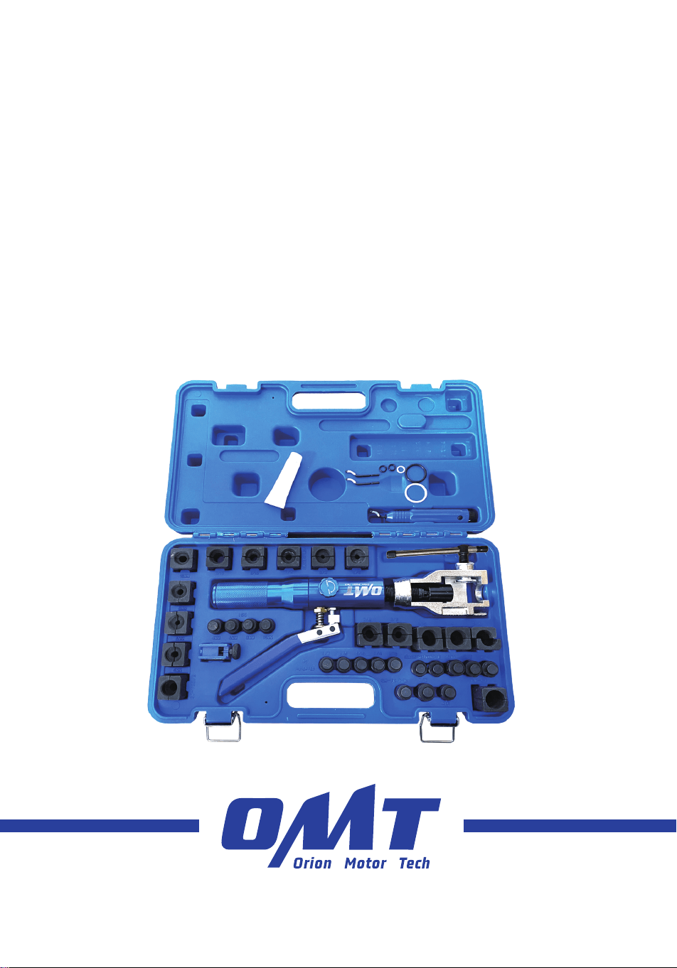
Hydraulic
Flaring Tool
User Manual


Contact Us
Thank you for choosing our products! If you have any questions or comments,
contact us and we'll address your issues ASAP!
https://orionmotortech.com/
@OrionMotorTech
Read this disclaimer completely and carefully before
proceeding with the rest of the manual content.
1. Product Modifications
Any modifications or alterations to OMT products void
any warranties and may result in damage or injury. OMT
shall not be liable for any damages resulting from such
modifications or alterations.
2. Compliance with Laws
Customers shall be liable for ensuring that the use of
OMT products complies with all applicable laws and
regulations in their respective jurisdictions. OMT assumes
no responsibility for any violations of laws or regulations
resulting from the use of OMT products.
3. Correct Use
Always use OMT products only as directed in the
accompanying manuals. Failure to follow instructions may
result in injury or damage.
Always ensure the assembly, installation, operation,
maintenance, or repair of OMT products is carried out by
a competent person.
Always make maintenance regularly throughout OMT
products’ lifecycles; you have the liability to keep the
products operating as intended.
Always wear appropriate protective gear.
4. Third-Party Products
OMT shall not be liable for any damages or losses
resulting from the use of third-party products in
conjunction with OMT products. Customers shall refer to
the third-party’s guidelines and/or warranties (if any) for
any third-party products used.
5. Limitation of Liability
OMT shall not be liable for any direct, indirect, punitive,
incidental, special, or consequential damages to property
or life, whatsoever arising out of or connected with the
use or misuse of OMT products. In no event shall OMT’s
liability exceed the value of the products sold.
6. Warranty
Refer to the sales page for the warranty information.
This disclaimer states the entire obligation of OMT with
respect to OMT products. If any part of this disclaimer is
determined to be void, invalid, unenforceable, or illegal,
including but not limited to the warranty disclaimers, liability
disclaimers, and liability limitations set forth above, the invalid
or unenforceable provision will be deemed superseded by
a valid and enforceable provision that most closely matches
the intent of the original provision and the remainder of the
agreement shall remain in full force and effect.
Disclaimer
1
Safety Information
• The instructions provided herein are only for general information. ALWAYS perform
all repairs in full compliance with your machinery’s service manual. After repairs, test
your engine and vehicle at low speed in your workshop BEFORE resuming use. Failure
to do so may lead to serious property damage and severe personal injury.
• DO NOT allow children, persons whose mental or physical condition precludes safe
use, or anyone unfamiliar with this product and its compatible systems to use it.
• DO NOT use while under the influence of alcohol, drugs, or any medication that
negatively affects your judgment or reflexes. Keep children and bystanders away
during use.
• Keep your work site clean and well-lit. Cluttered and dark work areas increase the risk
of accidents.
• For best results, keep the kit clean and dry. Remove any fluid, oil, or grease before and
after work.
• ALWAYS use personal protective equipment (PPE) suitable to your task. ALWAYS
wear ANSI and OSHA-approved eye, breathing, and hand protection while using this
product. Regular use of this product typically produces microscopic particles known
to the state of California to cause cancer, congenital disabilities, or other reproductive
harm. Nonslip footwear is also highly recommended. Other equipment such as ear,
head, and body protection may also be necessary depending on your work, work
environment, and other equipment.
• ALWAYS know and understand your machinery’s specific safety warnings and
instructions before using this kit. Use the correct fluids, pressures, adapters, etc.,
for your machinery. Make sure the machinery is fully supported and parked before
beginning any work. Ensure you do not make any contact with the heated surface.
• Dress appropriately for automotive servicing. DO NOT wear loose clothing or jewelry,
and keep hair, clothing, gloves, hoses, and tools away from any moving parts during
use.
• Before servicing your machinery, turn off its engine and refer to its manufacturer’s
service and repair manual for instructions on safely securing the machinery with
chocks, jacks, stands, etc.
• In case of an accident or injury, have a first aid kit and a communication device (e.g., a
phone) readily available. Know the location of emergency medical facilities.
• Maintain this product. Check for misalignment, binding, wear, or other damage before
use. If any damage is detected, repair or replace the problematic components before
continued use. In a large shop, mark such tools “DO NOT USE” until they have been
repaired. ON LY replace components with identical parts.
• Machinery repair is an inherently dangerous activity. This manual and the separate
machinery service manual cannot cover all possible situations that may arise.
ALWAYS exercise discretion and good judgment. Seek training if needed.
2
Specifications
Dimensions 17.5 × 10.1 × 3.4 in. 44.5 × 25.5 × 8.5 cm
Weight 13.4 lb. 6.08 kg
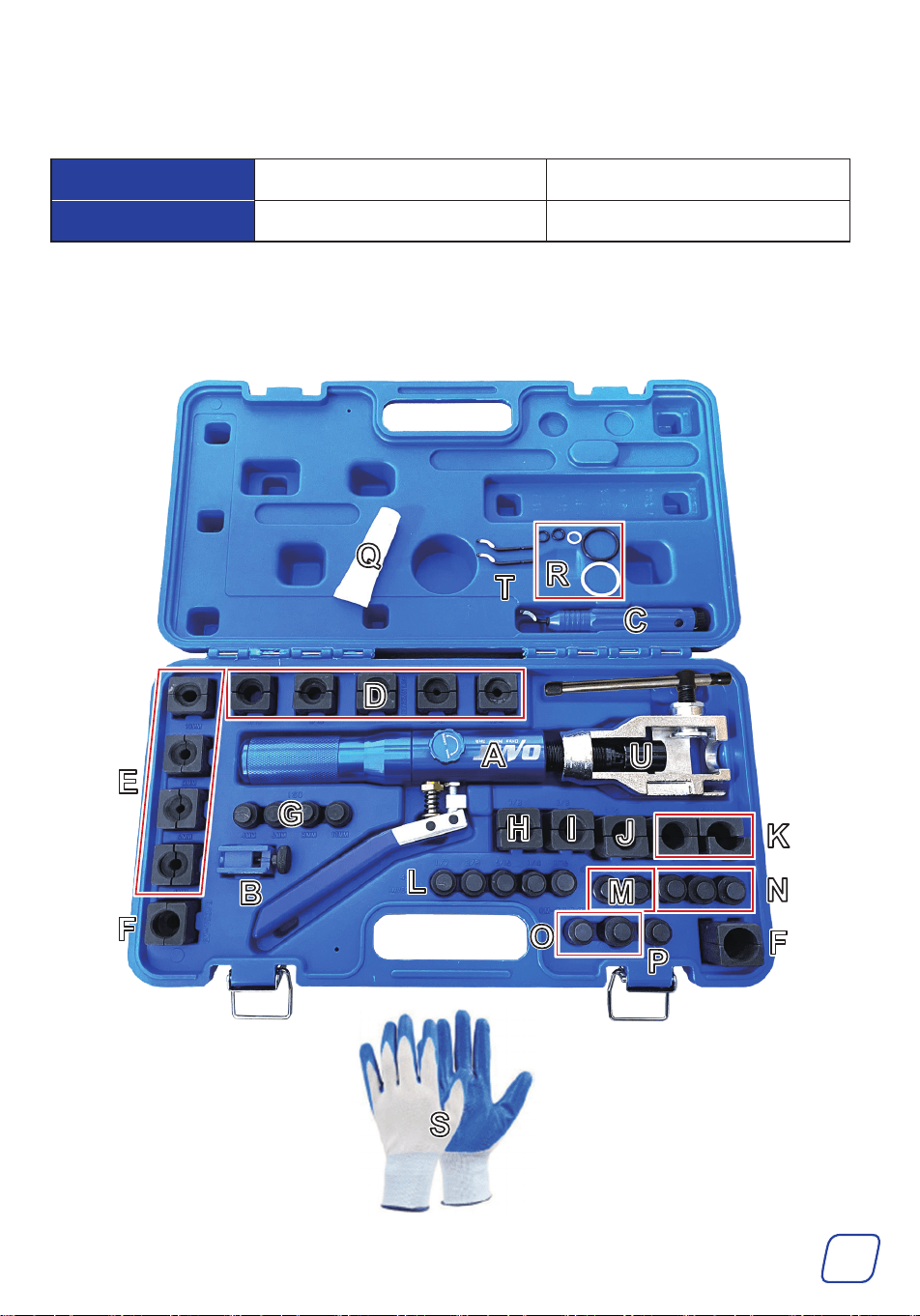
Parts List

3
Package List
No. Item Qty.
A Hydraulic Flaring Tool 1
B Cutter 1
C Deburring Tool 1
D
45° Inverted Dies
3/16 in.
5
5/16 in.
1/2 in.
3/8 in.
1/4 in.
E ISO Dies
10 mm
4
8 mm
6 mm
4 mm
F GM–TC Dies
3/8 in.
2
1/2 in.
G ISO Adapter
10 mm
4
8 mm
6 mm
4 mm
H
Push Connect Dies
3/8 in. 1
K
5/16 in.
2
1/4 in.
I
GM Fuel Line Dies
3/8 in. 1
J 5/16 in. 1
L 45° Inverted Adapters
3/16 in.
5
5/16 in.
1/2 in.
3/8 in.
1/4 in.
M GM Fuel Line Adapters
5/16 in.
2
3/8 in.
N Push Connect Adapters
3/8 in.
3
5/16 in.
1/4 in.
O GM–TC Adapters
3/8 in.
2
1/2 in.
P 45° Flaring Cone Adapter 1
Q Grease 1
R Sealing Rings 5
S Gloves 1 (Pair)
T Replacement Blades 2
U OP.0 Alignment Adapter 1
4
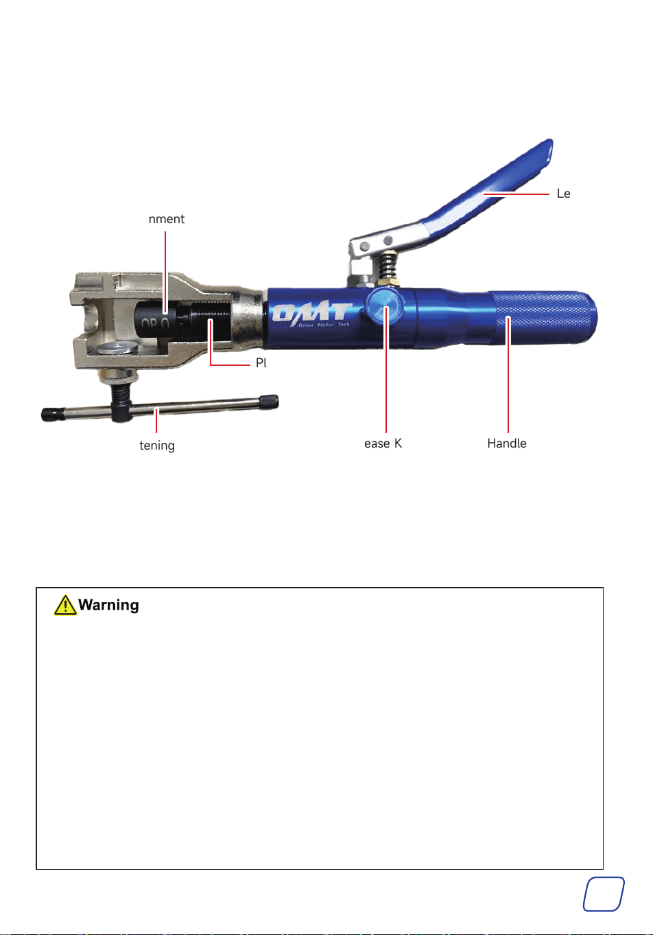
Product Diagram
Plunger
Lever
Tightening Bar
OP.0 Alignment Adapter
Release Knob Handle
Operation
• Use the correct tools and personal protective equipment (PPE) before operating. Be
EXTREMELY careful around possible pinching points, moving parts, or parts that may
suddenly spring out.
• Make sure your surroundings are safe when using the tool. Avoid operating in crowded or
unstable areas.
• Inspect the tool and hydraulic system for any leaks or damage before use.
• Use the appropriate dies and adapters based on the pipe diameter and type to ensure
quality flares.
• Maintain cleanliness of the pipes and dies to prevent debris from affecting the flaring
process.
• Apply pressure uniformly to avoid rapid or excessive force, which could deform or rupture
the pipe.
• For added safety, we recommend training before using these tools. A lack of training
could result in serious injury.
5
Preparing Your Pipe
Prepare pure copper pipes, copper-plated pipes, and other soft metal pipes.
• The pipe wall thickness must NOT exceed 1 mm.
• DO NOT use stainless steel pipes.
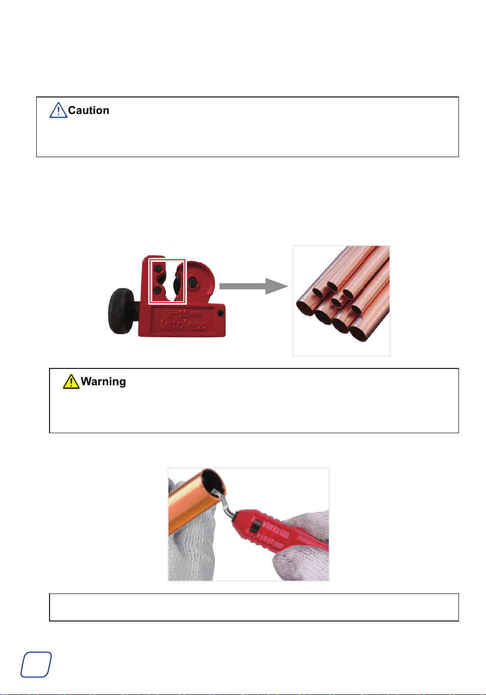
Cutting Your Pipe (Optional)
1. Use the cutter (B) to cut the pipe to your desired length by turning its knob.
• DO NOT use a hacksaw or cut-off wheel to cut the pipe.
• DO NOT place your finger or any part of your body near the blade of the cutter.
2. Remove any burrs from the cut edges using the deburring tool (C).
Note: Be sure to clear metal chips from inside the pipe.
6
Choosing the Appropriate Dies for Your Pipe
1. Choose the dies according to your pipe’s outer diameter.
• For a standard-sized pipe (such as 3/8″), choose dies of the same size from the provided dies.
• For a non-standard pipe, measure the pipe’s outer diameter and select the dies closest to the
measured diameter.
2. Sandwich the tube between the dies. Without applying pressure, a slight gap will remain between
them. If there is no gap, replace the pipe or the dies.
Note: Maintain a gap of 0.2–0.3 mm when the die specification is ≤ 3/16″ (imperial) or ≤ 6 mm
(metric). For specifications exceeding these measurements, maintain a 0.3–0.5 mm gap.
Forming Line Flares
If forming push connect lines, GM fuel lines, GM transmission cooling lines, or ISO
bubble flares:
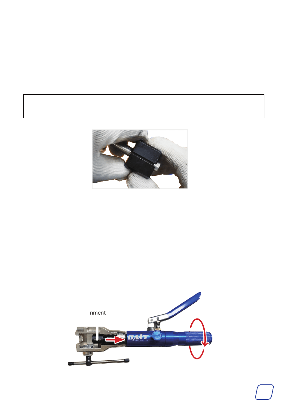
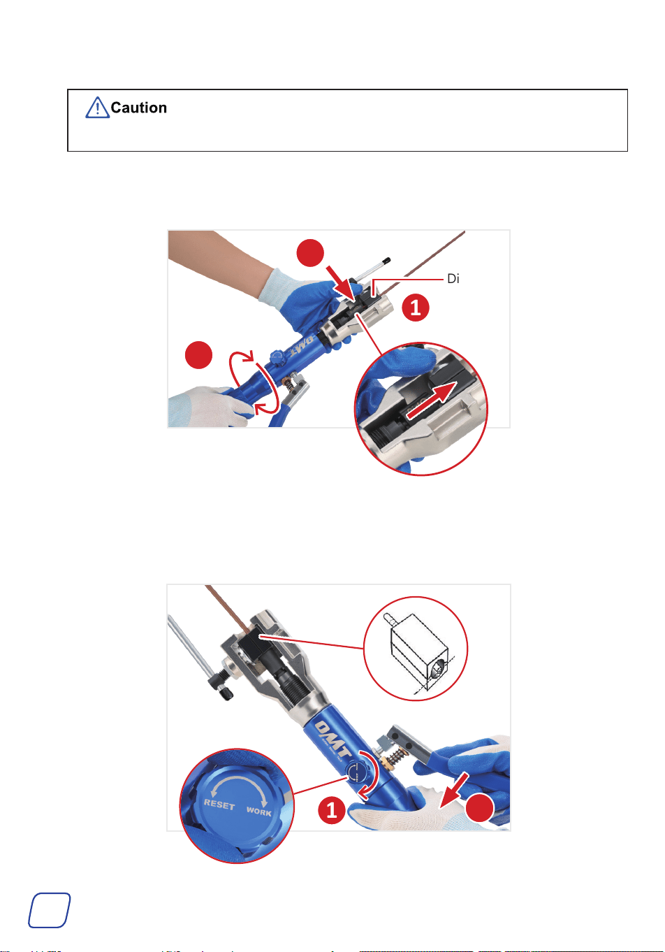
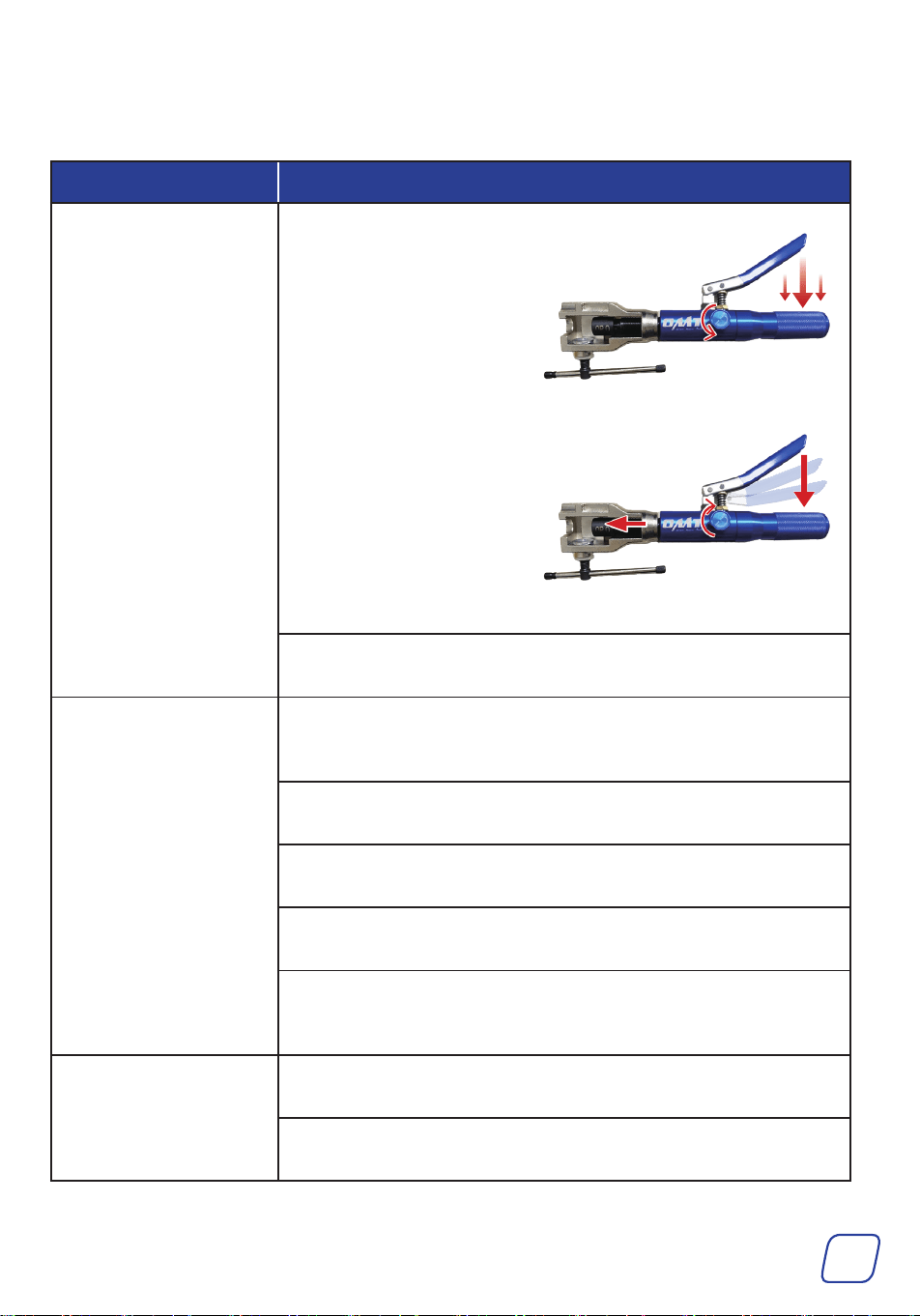
1. Place the OP.0 alignment adapter (U) onto the adapter seat. If necessary, rotate the handle of
the hydraulic flaring tool (A) counterclockwise to leave space for the dies.
OP.0 Alignment Adapter
7
2. Place the dies with the sandwiched pipe into the yoke.
The edge of the pipe must NOT be indented in the dies.
3. Rotate the tightening bar clockwise to secure the dies WITHOUT fully tightening them.
4. Rotate the hydraulic handle clockwise until the alignment adapter is against the pipe.
5. Rotate the release knob fully in the WORK direction. Squeeze the lever to push the alignment
adapter against the dies until you feel significant resistance from the pumping action, ensuring
the pipe’s edge aligns with the dies’ edge.
1
1
2
3
Dies
2
8
c. Select and insert the appropriate dies and adapter based on your needs.
Note:
• The dies and adapter must be properly matched. For
example, the 8 mm ISO dies must be used with the 8 mm
ISO adapter.
• Lubricating the adapter with the provided grease (Q)
BEFORE replacement helps remove the pipe later.
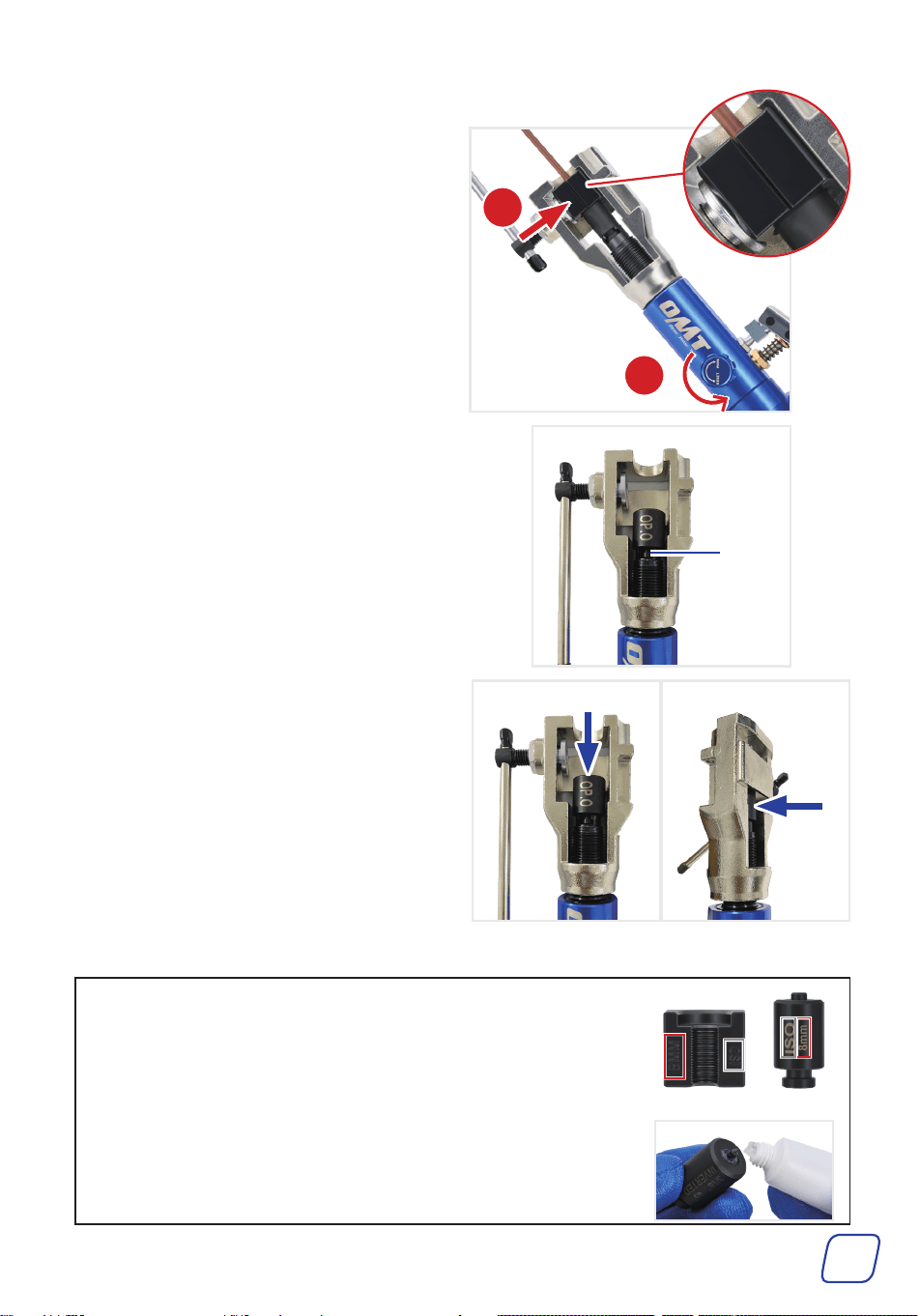
8. Repla ce the alignment adapter with the
corresponding adapter.
a. Turn the hydraulic handle counterclockwise
until the notch on the plunger faces you.
6. Rotate the release knob fully in the RESET
direction to release the pressure.
7. Rotate the tightening bar clockwise to
tighten the dies further until there is almost
no gap between them.
1
2
Die Adapter
Notch
b. Press the adapter and gently push the
adapter from the backbackward at the
same time to release it from the plunger.
Press
Push
9
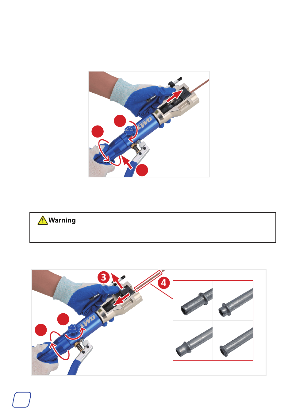
11. Rotate the release knob fully in the RESET direction to release the pressure.
12. Rotate the hydraulic handle counterclockwise to keep the adapter away from the dies.
• DO NOT loosen the tightening bar until the adapter is outside of the dies.
13. Loosen the tightening bar, and then remove the dies and pipe.
9. Rotate the hydraulic handle clockwise until the handle cannot be turned further. The adapter
should engage the dies.
10. Rotate the release knob fully in the WORK direction. Squeeze the lever to push the adapter
against the dies until you feel significant resistance from the pumping action.
1
2
2
1
3
3
4
10
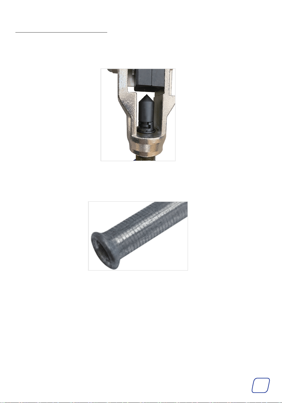
If forming 45˚ and double flares:
1. Follow Steps 1–12 in Forming Push Connect or GM Fuel Line Flares.
2. Replace the male adapter with the 45° flaring cone adapter (P).
3. Follow Steps 9–13 in Forming Push Connect or GM Fuel Line Flares.
11
• If the hydraulic oil leaks at the plunger, replace the sealing rings inside the hydraulic flaring tool.
a. Remove the OP.0 alignment adapter, yoke, plunger, spring, and piston.
b. Remove the black sealing ring. Then, cut and remove the white ring. Install the provided
sealing rings in place.
Maintenance
• After use, clean the tools with a soft, damp cloth and a mild detergent or solution. DO NOT
rinse them or use abrasive cleaners or caustic chemicals.
• For best results, lubricate the tools with high-quality anti-corrosive oil between uses.
• Check the tool's parts periodically for wear or damage after each use. Repair or replace any
problematic parts before continued use.
• If the tools will not be used for an extended period, clean and lubricate them and store them
in a cool, dry place inaccessible to children.
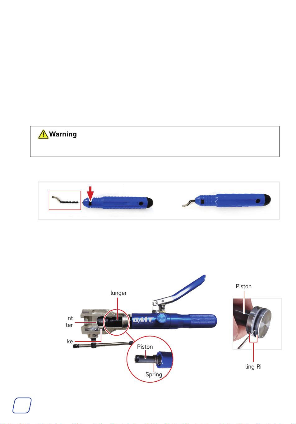
• If the blade of the deburring tool is no longer sharp enough, you can replace it with the
replacement blade provided.
Wear protective gloves to avoid scratching your hands with the blade.
a. Press the button on the deburring tool and pull out the blade.
b. Press the button and fully insert the blade until the button pops back up.
OP.0 Alignment
Adapter
Yo ke
Plunger
Piston
Sealing Rings
Spring
Piston
12
Troubleshooting
Problems Solutions
After squeezing the
lever, the adapter either
does not rise or bounces
back after ascending.
1. Rotate the release knob
fully in the RESET direction.
Squeeze the lever quickly
for about 10 seconds to
allow the hydraulic oil inside
the machine to circulate.
2. Rotate the knob fully in the
WORK direction. Squeeze
the lever a few times to
check if the adapter is
pushed up properly.
3. If not, repeat the steps 2 to 3 times.
If it still doesn't work, contact customer service or seek a professional
to repair the internal hydraulic system.
Poor sealing after flaring
Ensure the pipe is made of soft metal, such as pure copper or copper-
plated. NEVER use stainless steel. The pipe's thickness must NOT
exceed 1 mm.
Before flaring, clean the pipe surface thoroughly to remove dirt, oxide
layers, and other contaminants and ensure that it is smooth and flat.
Ensure the appropriate dies and adapters are used based on the pipe
diameter and type.
Ensure the lever is squeezed evenly and regularly during
pressurization. Avoid applying too much or too fast pressure.
Correctly use the OP.0 alignment adapter and dies to ensure the
pipe’s edge is aligned with the dies’ edge, ensuring the pipe maintains
the correct position and angle during the expansion process.
Hydraulic oil leaks at the
plunger or lever
If the oil leaks at the plunger, check whether the sealing rings show
signs of aging. If it does, replace the faulty rings.
If the oil leaks at the lever, contact customer service or seek a
professional to replace the inner sealing rings.

User Manual
Rev. 19 Jun. 2025