Vacuum Brake Bleeder Kit
with Relling Bottle
User Manual
UM-BBT-0027-V1
Read Carefully Before Use
Keep for Future Reference

Disclaimer
Read this disclaimer completely and carefully before proceeding with the rest of the manual
content.
1.
Product Modications
Any modications or alterations to Orion Motor Tech products void any warranties and may
result in damage or injury. Orion Motor Tech shall not be liable for any damages resulting
from such modications or alterations.
2.
Compliance with Laws
Customers shall be liable for ensuring that the use of Orion Motor Tech products complies
with all applicable laws and regulations in their respective jurisdictions. Orion Motor Tech
assumes no responsibility for any violations of laws or regulations resulting from the use of
Orion Motor Tech products.
3.
Correct Use
Always use Orion Motor Tech products only as directed in the accompanying manuals.
Failure to follow instructions may result in injury or damage.
Always ensure the assembly, installation, operation, maintenance, or repair of Orion Motor
Tech products is carried out by a competent person.
Always make maintenance regularly throughout Orion Motor Tech products’ lifecycles; you
have the liability to keep the products operating as intended.
Always wear appropriate protective gear.
4.
Third-Party Products
Orion Motor Tech shall not be liable for any damages or losses resulting from the use of
third-party products in conjunction with Orion Motor Tech products. Customers shall refer to
the third-party's guidelines or/and warranties (if any) for any third-party products used.
5.
Limitation of Liability
Orion Motor Tech shall not be liable for any direct, indirect, punitive, incidental, special, or
consequential damages to property or life, whatsoever arising out of or connected with the
use or misuse of Orion Motor Tech products. In no event shall Orion Motor Tech’s liability
exceed the value of the products sold.
6.
Warranty
Refer to the sales page for warranty information.
This disclaimer states the entire obligation of Orion Motor Tech with respect to Orion Motor Tech
products. If any part of this disclaimer is determined to be void, invalid, unenforceable, or illegal,
including but not limited to the warranty disclaimers, liability disclaimers, and liability limitations
set forth above, the invalid or unenforceable provision will be deemed superseded by a valid
and enforceable provision that most closely matches the intent of the original provision and the
remainder of the agreement shall remain in full force and eect.

3
Safety Information
• Read these instructions carefully before use.
• Store this manual for future reference. Include this manual with the kit if it is ever given or sold
to a third party.
• ONLY use this kit for its intended purpose: draining air from the braking system and replacing
old brake uid.
• ONLY use this kit according to these instructions, the vehicle manufacturer’s guidelines, and all
applicable local and national laws and regulations. Improper use may cause res, explosions,
serious property damage, or severe personal injury, including death.
• ONLY trained personnel should use this kit. Vehicle maintenance can be dangerous and must
be done carefully and responsibly.
• DO NOT allow children or anyone with impaired mental or physical capabilities to use this kit.
• DO NOT use it while under the inuence of alcohol, drugs, or any medication that negatively
aects your judgment or reexes.
• NEVER use this kit for or around highly ammable, corrosive, or explosive uids and gases
such as gasoline, strong acids, and brake uids.
• NEVER smoke or allow open ames around ammable or explosive uids and gases.
• Keep your work site clean and well-lit. Cluttered and dark work areas invite accidents.
• Keep your work site well-ventilated. NEVER run your vehicle’s engine in a tightly enclosed
space. IM ME DI ATELY stop the engine and improve ventilation if you experience eye, nose, or
throat irritation during work.
• ALWAYS review and understand your vehicle’s safety warnings and instructions before using
this kit. Use the correct uids, pressures, adapters, etc., for your vehicle. Ensure your vehicle is
securely parked or held in place before beginning any work.
• NEVER touch any heated surface or uid with exposed skin.
• NEVER open a cap such as those on a radiator or expansion tank if it could release hot or
pressurized uid or vapor.

4
• For best results, keep the kit clean and dry. Remove any uid, oil, or grease before and after
work, particularly from the handle and ttings. Maintain the product’s labeling. Contact customer
service if replacements are needed.
• ONLY use this kit with personal protective equipment (PPE) appropriate for your work. Always
wear ANSI-approved eye and hand protection while using this kit. Nonslip footwear is highly
recommended. Ear, head, and body protection may also be necessary, depending on your
work and other equipment. Keep unprotected bystanders at a safe distance.
• Dress properly for your work. DO NOT wear loose clothing or jewelry. Keep hair, clothing,
gloves, hoses, and tools away from any moving parts during use.
• DO NOT overreach. Keep proper footing and balance at all times.
• DO NOT use excessive pressure with this kit, and DO NOT force it or its attachments.
• Maintain this kit properly, and keep it dry and clean after use. Check for misalignment or binding
of parts, wear or breakage, or any other issues that could aect this kit’s safe operation. In
the event of damage or malfunction, ensure that aected part(s) are repaired or replaced by
a trained technician before continued use. In a large workshop, mark such tools as “DO NOT
USE” until they are repaired. Only replace parts with identical components.
• DO NOT pour waste brake uid down the drain, into a drain outlet, or into the soil to avoid
contaminating the environment.
• Disposal regulations for hazardous waste may vary by region. Before disposing of used brake
uid, it is advisable to consult your local government or environmental protection department
for local waste disposal regulations.
Safety Information
5
Specications
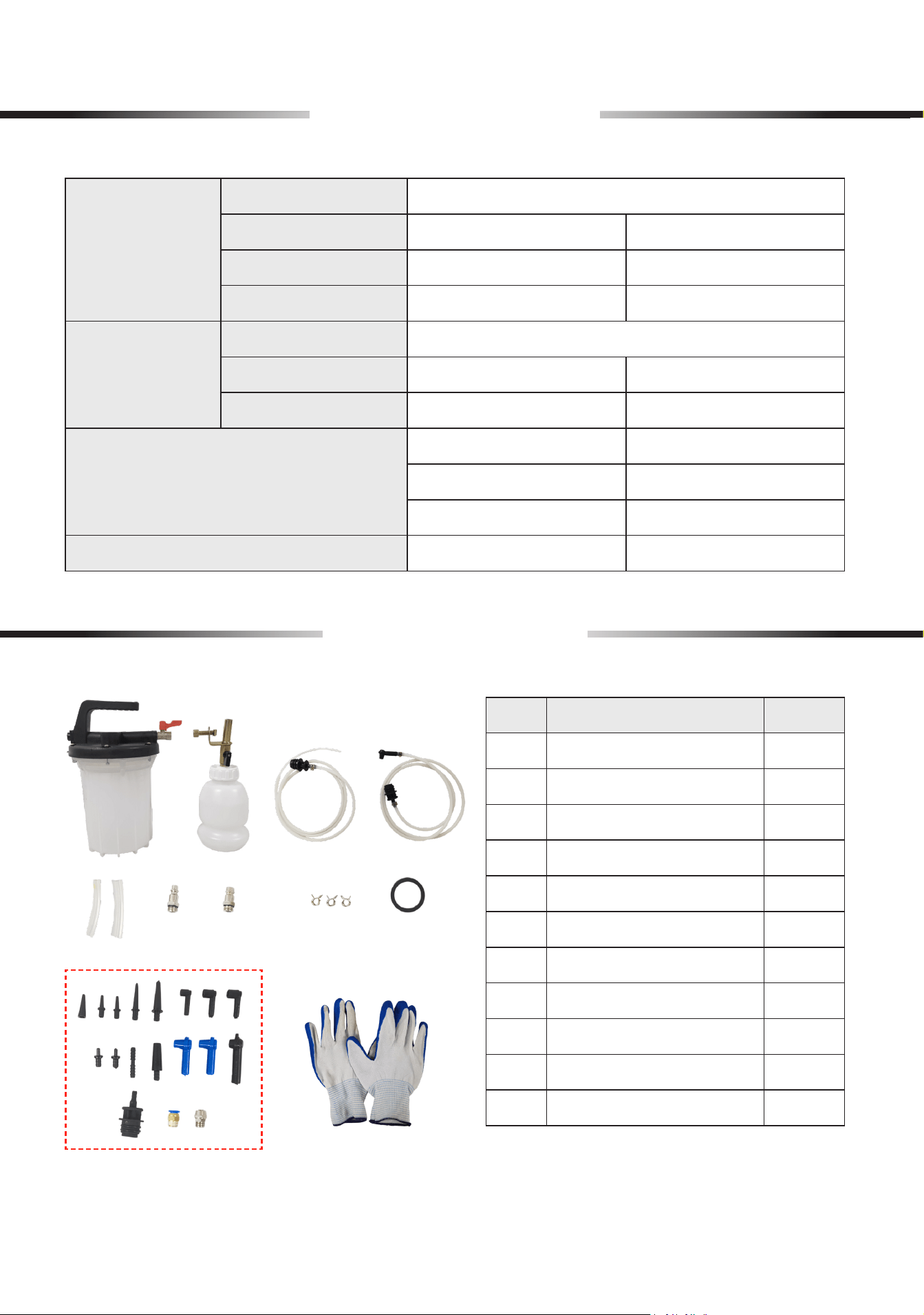
Package List
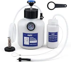
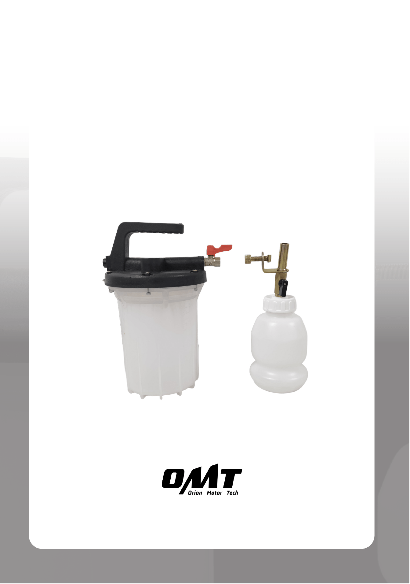
Vacuum Brake
Bleeder
Material
PP, Nylon, Aluminum, Pure Copper, and Q235
Capacity
3.17 qt. (0.79 gal.) 3 L
Air Valve Inlet Dia.
0.24 in. 6 mm
Dimensions
9.6 × 7.7 × 12.2 (in.) 24.5 × 19.5 × 31 (cm)
Relling Bottle
Material
PP, PE, Pure Copper, and Q235
Capacity
1.06 qt. (0.26 gal.) 1 L
Dimensions
4.9 × 4.3 × 10.8 (in.) 12.5 × 11 × 27.5 (cm)
Hose Lengths
72.4 in. 184 cm
66.9 in. 170 cm
2.8 in. 7 cm
Net Weight
3.5 lb. 1.59 kg
No. Name Qty.
A Vacuum Brake Bleeder 1
B Relling Bottle 1
C Extractor Hose 1
D Bleeding Hose 1
E Tubes 2
F American Air Intake 1
G European Air Intake 1
H Bleed Screw Adapters 18
I Hose Clamps 3
J Rubber Ring 1
K Gloves 1 (Pair)
Not Included but Helpful:
Box-End Wrench
AA
BB CC
II
JJ
KK
DD
EE
HH
GGFF
6
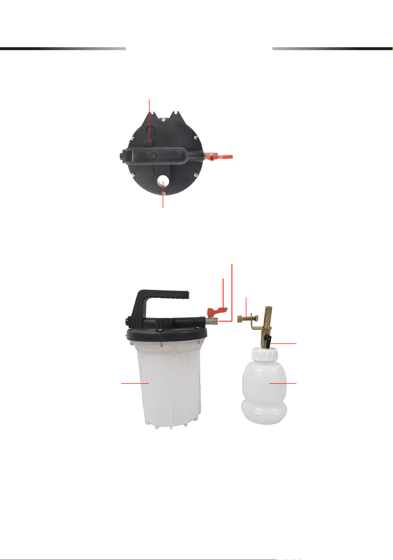
Product Diagram
Air Control Valve
Swivel Clamp
Switch Valve
1 L Relling Bottle3 L Vacuum Brake Bleeder
Air Valve Inlet
Pressure Release Valve
Inlet Port
7
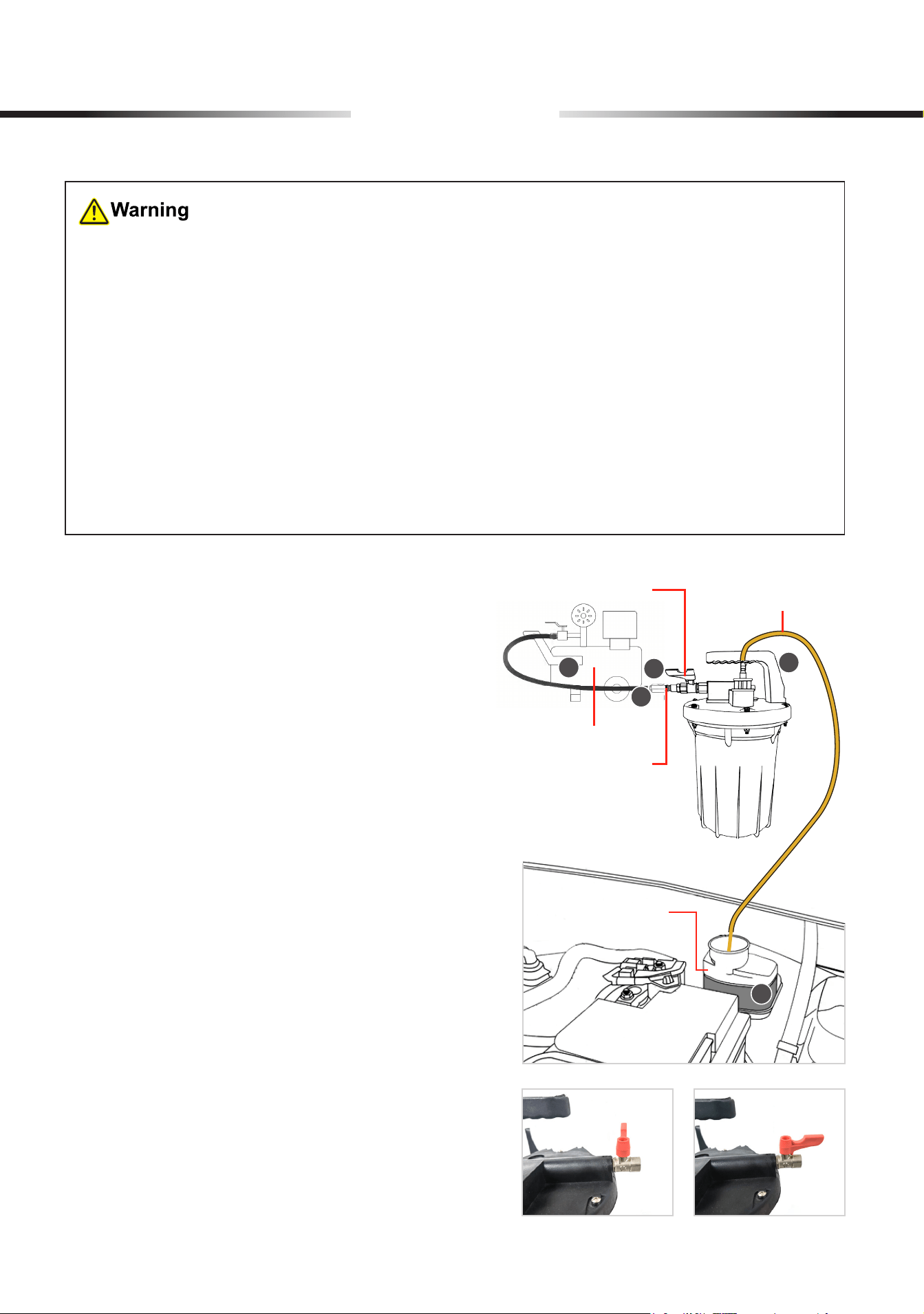
Operation
Extractor Hose
Master Cylinder
Reservoir
Air Control Valve
Extracting the Old Brake Fluid
1. Ensure that the vehicle is turned o. Turn it to
Neutral for manual transmissions, or turn it to
Park for automatic transmissions. Activate the
parking brake.
2. Choose an air intake (F or G) and securely
connect it to the air valve inlet on the vacuum
brake bleeder.
3. Secure the extractor hose (C) to the inlet port.
4. Remove the cap from the master cylinder
reservoir and insert the extractor hose.
5. Connect an air compressor to the air valve inlet
on the brake bleeder and set the compressor.
The recommended pressure range is 70−170
psi (4.8−11.7 bar).
6. Turn on the air control valve and activate the air
compressor to extract the old uid.
7. After extraction, remove the extractor hose,
switch o the air compressor, and turn o the air
control valve.
• ALWAYS follow your vehicle manufacturer's service manual for the recommended type and
amount of transmission uid.
• Put on your PPE, always including ANSI-approved safety glasses and work gloves.
• Raise your vehicle if needed, using appropriate safety stands to prevent potentially fatal
accidents.
• ALWAYS e n s u r e t h a t th e b r a ke u i d t o b e a d d e d ma tc he s yo u r v e h i c le’s sp ec i c r e qu i r e m e n t s
to prevent damage to the braking system.
• DO NOT open the vacuum brake bleeder’s pressure release valve during use. Doing so
will introduce air into the system, causing reduced eciency, malfunction, or even safety
hazards like explosions.
• ALWAYS work in a well-ventilated area, as brake uid can emit harmful vapors.
2
3
4
5
6
Air Control Valve OFF Air Control Valve ON
Air Intake
Air Compressor
8
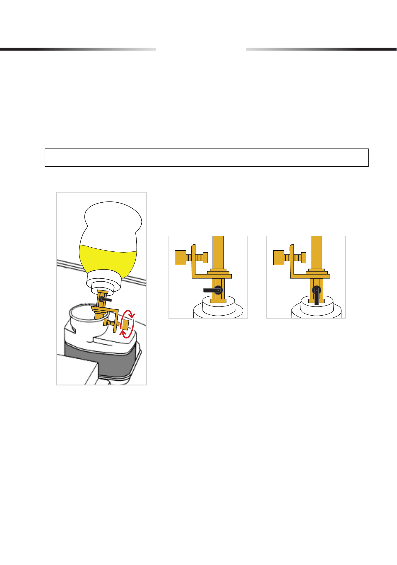
Adding the New Brake Fluid
1. Unscrew the relling bottle’s cap, ll the new brake uid into the bottle, and retighten the cap.
2. Fix the relling bottle on the reservoir by tightening the swivel clamp clockwise.
3. Turn on the switch valve and start lling.
Note: ALWAYS keep the reservoir lled to prevent air from entering the brake system.
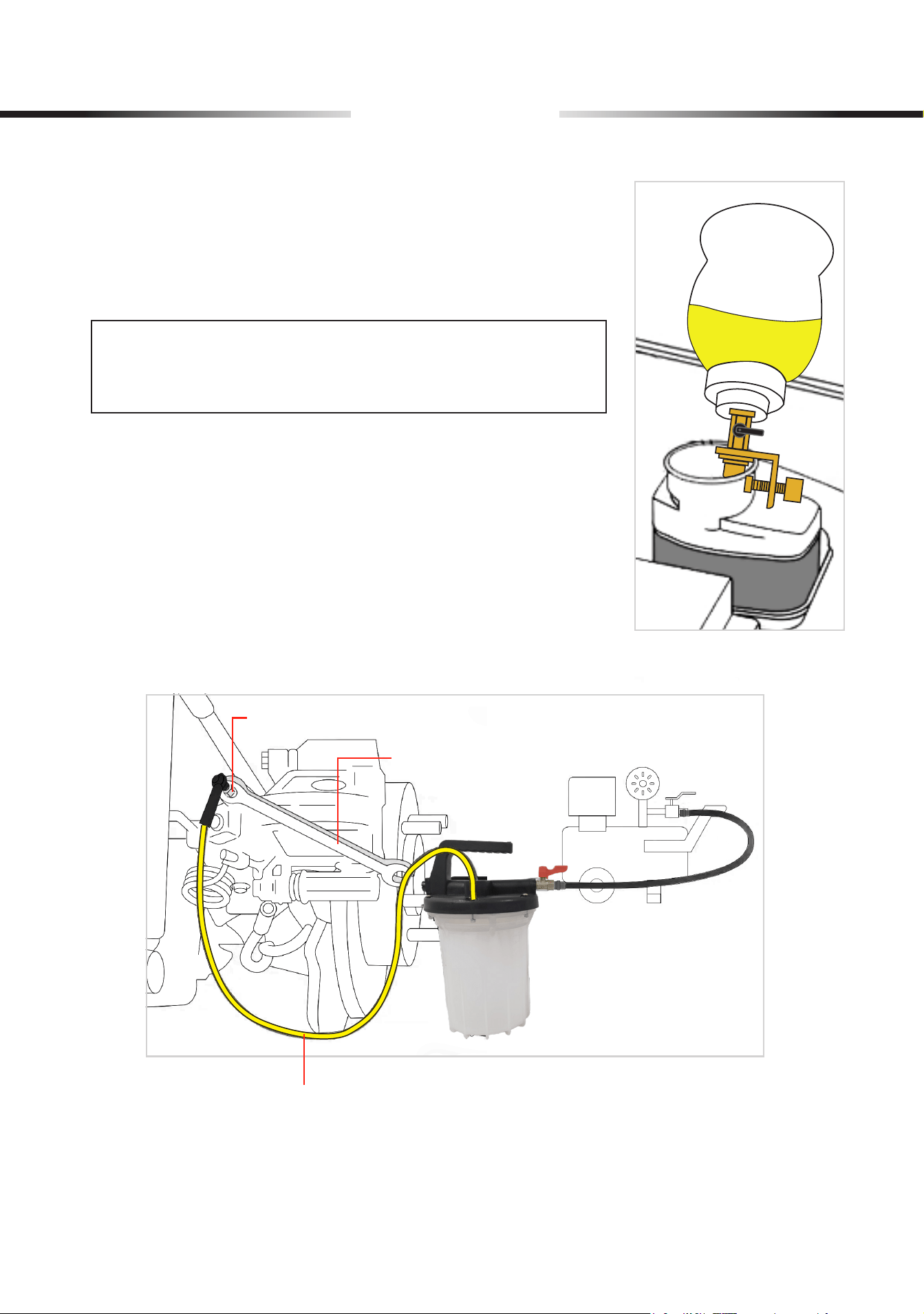
Bleeding the Brake Fluid
1. Remove the extractor hose and connect the bleeding hose (D) to the inlet port.
2. Locate the tire farthest from the reservoir and identify the bleed screw near it.
3. Remove the bleed screw cap and attach the bleeding hose with the adapter to the screw.
4. Use a box-end wrench (not included) to loosen or open the bleed screw.
Operation
Switch Valve OFF Switch Valve ON
9
Operation
5. Keep the air compressor connected and set it within the
recommended pressure range of 70−170 psi (4.8−11.7 bar).
6. Turn on the air control valve and activate the air compressor to
bleed the brake uid.
Note:
Old brake uid is extracted while new brake uid is added at
the same time.
7. Continue bleeding the old brake uid until you see new, cleaner
brake uid being extracted. (The new uid is lighter in color.)
Bleeding Hose
Bleed Screw
Box- E nd
Wrench
10
Maintenance
• Use detergent and water to rinse the kit and clean the inner surfaces of the hoses. Dry the kit
COMPLETELY before continued use.
• Check for loose connections, wear, and damage before and after each use. Tighten, repair, or
replace ANY aected or damaged components before further use. ONLY use identical parts
as replacements.
• If this kit will not be used for an extended period, store it in a cool and dry location, away from
direct sunlight and out of children’s reach.
8. Start from the tire farthest from the reservoir to the one nearest to it. Repeat the process for
each wheel in succession.
Note: While the uid is being changed, regularly check the level in the relling bottle.
9. After bleeding, switch o the air compressor and disconnect it from the brake bleeder. Remove
the top adapter of the bleeding hose from the inlet port. Pour the old brake uid into the waste
oil barrel.
• ALWAYS wear proper PPE, such as gloves and goggles, when handling waste brake
uid to prevent exposure to hazardous substances.
• Hazardous waste disposal regulations vary by region and require spent brake uid to be
disposed of according to local standards.
• NEVER mix waste brake uid with other chemicals as this may cause a dangerous
chemical reaction.
• Ensure that waste brake uid is stored in sealed containers away from sources of ignition
and children to prevent accidents.
Operation

11
Troubleshooting
Problems Solutions
Slow Extraction
Speed
Check for blockages or obstructions in the tubes; Clean or replace
any blocked components.
Verify the air pressure source to ensure it is within the specified
range for the equipment.
Inspect the hoses for twists or bends that may aect ow speed.
Leakage Issues
Check the tightness of hose connections to ensure there are no
loose ttings.
Inspect the hoses, tubes, adapters, clamps, and other components
for damage or wear; Promptly replace any affected or damaged
components.
Ensure that the clamps are securely fastened to the hose
connections.
Air Remaining in the
Brake System
Ensure to start bleeding from the wheel farthest from the brake
master cylinder and work your way closer.
Ensure there are no damaged or loose hoses. Tighten all
connections securely.
Problems with brake pads or discs can indirectly aect the bleeding
process. Ensure all brake components are in good condition.
Relling Bottle Not
Functioning Properly
Ensure the relling bottle is properly sealed without any cracks or
deformations.
Verify that the brake uid can ow freely from the relling bottle to
the master cylinder. Check for any blockages.

Rev. 20 Jan. 2025
Thank you for choosing our products! If you have any questions or
comments, contact us and we'll resolve your issues ASAP!
support@orionmotortech.com
Contact Us
Scan for the latest
user manual