tM
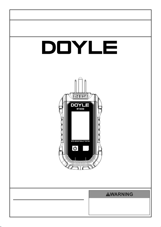
GFCI RECEPTACLE TESTER
Visit our website at: https://www.harborfreight.com
email our technical support at: [email protected]
59524
HOLD
GFCI
SEC VAC
REVERSE
OPEN GRD HOT GRD
NEU HOT HOT NEU
TEST
TM
GFCIPUSH TO RESET
CORRECT FAULT
Owner’s Manual & Safety Instructions
Save This Manual Keep this manual for the safety warnings and precautions, assembly,
operating, inspection, maintenance and cleaning procedures. Write the product’s date code in the back of
the manual (or month and year of purchase if product has no number). Keep this manual and the receipt in a
safe and dry place for future reference. 25k
When unpacking, make sure that the product is intact
and undamaged. If any parts are missing or broken,
please call 1-800-444-3353 as soon as possible.
Copyright
©
2025 by Harbor Freight Tools
®
. All rights reserved.
No portion of this manual or any artwork contained herein may be reproduced in
any shape or form without the express written consent of Harbor Freight Tools.
Diagrams within this manual may not be drawn proportionally. Due to continuing
improvements, actual product may differ slightly from the product
described herein. Tools required for assembly and service may not be included.
read this material before using this
product. Failure to do so can result in
serious injury. SaVe tHiS ManuaL.
Page 2 For technical questions, please call 1-800-444-3353. Item 59524
SaFety OperatiOn MaintenanceSetup
tM
WarninG SyMBOLS anD DeFinitiOnS
This is the safety alert symbol. It is used to alert you to potential
personal injury hazards. Obey all safety messages that
follow this symbol to avoid possible injury or death.
Indicates a hazardous situation which, if not avoided,
will result in death or serious injury.
Indicates a hazardous situation which, if not avoided,
could result in death or serious injury.
Indicates a hazardous situation which, if not avoided,
could result in minor or moderate injury.
Addresses practices not related to personal injury.
iMpOrtant SaFety inFOrMatiOn
Safety Warnings and precautions
read all safety warnings and all instructions.
Failure to follow the warnings and instructions may result in electric shock, fire and/or serious injury.
Save all warnings and instructions for future reference.
1. All appliances or equipment on the circuit
being tested should be unplugged to
help avoid erroneous readings.
2. Not a comprehensive diagnostic instrument
but a simple instrument to detect nearly all
probable common improper wiring conditions.
3. Refer all indicated problems to
a qualified electrician.
4. Will not indicate quality of ground.
5. Will not detect 2 hot wires in circuit.
6. Will not detect a combination of defects.
7. Will not indicate reversal of neutral
and grounding conductors.
8. Consult the GFCI manufacturer’s installation
instructions to determine that the GFCI
is manufacturer’s specifications.
9. Check for correct wiring of receptacle
and all remotely connected receptacles
on the branch circuit.
10. Operate the test button on the GFCI installed in
the circuit. The GFCI must trip. If it does not - do
not use the circuit - consult an electrician. If the
GFCI does trip, reset the GFCI. Then, insert the
GFCI tester into the receptacle to be tested.
11. Activate the test button on the GFCI tester when
testing the GFCI condition. A visible indication
on the GFCI tester must appear when tripped.
12. If the tester fails to trip the GFCI, it suggests:
a. A wiring problem with a totally
operable GFCI; or
b. Proper wiring with a faulty GFCI.
Consult with an electrician to check the
condition of the wiring and GFCI.
Page 3For technical questions, please call 1-800-444-3353.Item 59524
SaFetyOperatiOnMaintenance Setup
13. Verify proper operation on a known source before
use or taking action as a result of the indications of
the device or, a positive means (visual or audible)
to indicate the unit is operating properly must be
provided. This indication or operation shall be
easily distinguishable from other operating modes.
In addition, the accompanying documentation
must state that the operator needs to verify
proper operation before use or taking action
as a result of the indications of the device.
14. Do not use the Tester if:
a. The battery is low.
b. Near any explosive gasses or fumes.
c. Any abnormal operation is detected.
d. The battery cover is open.
15. Power this Tester using only the battery(ies)
referenced in the Specifications Chart.
16. Avoid electrical shock. Use extreme caution
when working near uninsulated conductors or
bus bars. Prevent body contact with grounded
surfaces such as pipes, radiators, ranges, and
cabinet enclosures when testing voltages.
17. Observe work area conditions. Do not test voltages
in damp or wet locations. Tester is intended for
indoor use only. Keep work area clean and well lit.
18. Keep children away. Children must
never be allowed in the work area.
19. Stay alert. Watch what you are doing,
use common sense. Do not operate
any Tester when you are tired.
20. Do not operate Tester if under the influence
of alcohol or drugs. Read warning labels on
prescriptions to determine if your judgment
or reflexes are impaired while taking drugs. If
there is any doubt, do not operate the Tester.
21. People with pacemakers should consult their
physician(s) before use. Electromagnetic fields in
close proximity to heart pacemaker could cause
pacemaker interference or pacemaker failure.
22. Dress properly. Protective, electrically
nonconductive clothes and nonskid footwear
are recommended when working.
23. Wear ANSI-approved safety goggles during use.
24. Tester is designed for use with North
American 120VAC electrical outlets. DO
NOT connect to higher voltage electrical
supplies. For use on 3-wire outlets only.
25. Do not use Tester if damaged in any way.
Use only as specified in this manual.
26. Performance of this Tester may vary
depending on battery condition.
27. The warnings, cautions, and instructions discussed
in this instruction manual cannot cover all possible
conditions and situations that may occur. It must
be understood by the operator that common sense
and caution are factors which cannot be built into
this product, but must be supplied by the operator.
SaVe tHeSe inStructiOnS.
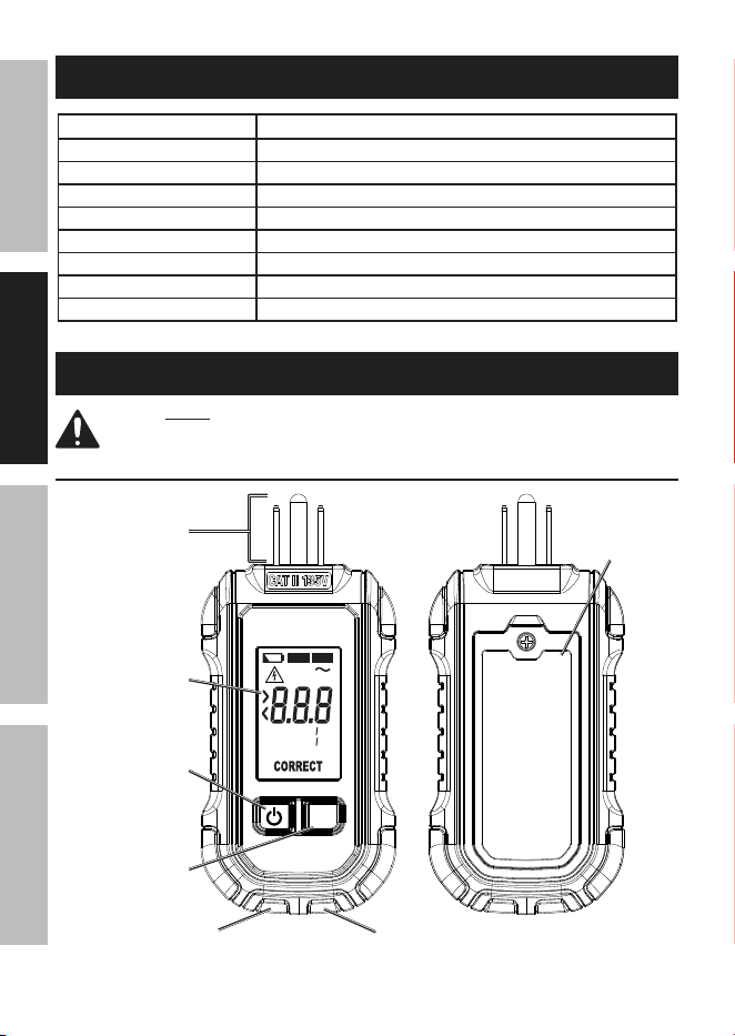
Symbology
WARNING marking concerning
Risk of Electric Shock.
Page 4 For technical questions, please call 1-800-444-3353. Item 59524
SaFety OperatiOn MaintenanceSetup
Specifications
Voltage Measurement Range
30~135VAC / 50~60Hz / Accuracy: 2% ± 2
Operating Altitude 6562 ft (2000 m)
Relative Humidity <85% Non-Condensing
Operating Temperature Range: 32°F - 122°F (0°C - 50°C)
Storage Temperature Range: -4°F - 140°F (-20°C - 60°C)
Safety Rating CAT II 135V
Display Liquid Crystal Display (LCD)
Battery (2) AAA (Included)
Pollution Degree PD2
Setup - Before use:
read the entire iMpOrtant SaFety inFOrMatiOn section at the beginning of this
manual including all text under subheadings therein before set up or use of this product.
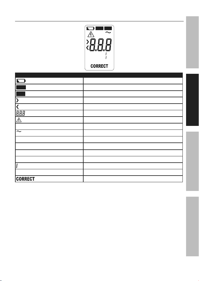
Functions
plug
HOLD
GFCI
SEC VAC
REVERSE
OPEN GRD HOT GRD
NEU HOT HOT NEU
TEST
power Button
GFci test Button
correct
indicator LeD
Fault
indicator LeD
LcD Display
Battery cover
Page 5For technical questions, please call 1-800-444-3353.Item 59524
SaFetyOperatiOnMaintenance Setup
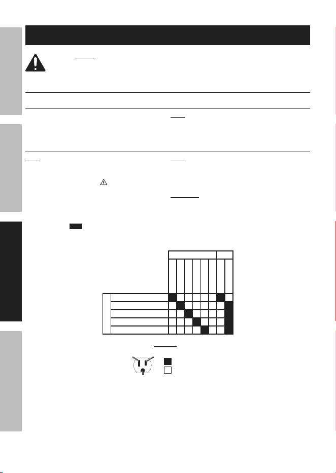
Display
HOLD
GFCI
SEC VAC
REVERSE
OPEN GRD HOT GRD
NEU HOT HOT NEU
Symbol Description
sec
OPEN GRD NEU HOT
HOT GRD NEU REV
Battery low
HOLD
Hold mode
GFCI
GFCI mode
Greater than
Less than
GFCI trip time reading and Voltage value reading
Hazardous voltage
SEC
Seconds
VAC
Voltage alternating current
OPEN
Open fault
GRD
Ground fault
HOT
Hot fault
NEU
Neutral fault
Divider
REVERSE
Reverse fault
Correct Wiring
Fcc Statement
Changes or modifications not expressly approved by Harbor Freight Tools
could void the user’s authority to operate the equipment.
NOTE: This equipment has been tested and found to comply with the limits for a Class B digital device, pursuant to
part 15 of the FCC Rules. These limits are designed to provide reasonable protection against harmful interference
in a residential installation. This equipment generates uses and can radiate radio frequency energy and, if not
installed and used in accordance with the instructions, may cause harmful interference to radio communications.
However, there is no guarantee that interference will not occur in a particular installation. If this equipment does
cause harmful interference to radio or television reception, which can be determined by turning the equipment
off and on, the user is encouraged to try to correct the interference by one or more of the following measures:
- Reorient or relocate the receiving antenna.
- Increase the separation between the equipment and receiver.
- Connect the equipment into an outlet on a circuit different from that to which the receiver is connected.
- Consult the dealer or an experienced radio/TV technician for help.
Page 6 For technical questions, please call 1-800-444-3353. Item 59524
SaFety OperatiOn MaintenanceSetup
Operating instructions
read the entire iMpOrtant SaFety inFOrMatiOn section at the beginning of this manual
including all text under subheadings therein before set up or use of this product. electrical
shock can cause death or injury! neVer tOucH exposed conductors of electricity.
General Operating instructions
powering the tester
1. Unplug Tester from outlet (if necessary).
2. Press and hold Power Button two seconds
to turn on Tester. LCD will display 000.
note: Tester will auto-power off
after 3 minutes of inactivity.
Wiring condition testing
note: Unplug any appliances or equipment from
the circuit being tested to prevent false readings.
1. Turn on Tester and plug into outlet of Circuit being
tested. LCD will display , and either the Correct
(green) or Fault (red) LED indicator will light.
2. If Fault (red) LED indicator lights:
a. Unplug Tester
b. Read voltage and fault. LCD will
display
HOLD
and LED’s will blink. Test
information will be held for 10 seconds
or until tester is plugged in again.
note: Red Fault LED will light if voltage detected
is low (30-85VAC) or high (>135VAC). It is possible
to have both the red Fault LED (indicating low or
high voltage) and green Correct LED (indicating
wiring is correct) light up simultaneously.
WarninG! tO preVent SeriOuS inJury: If wiring
condition fault is detected, consult a qualified electrician.
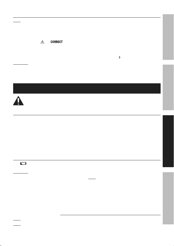
3. Reference fault chart for your wiring condition.
LcD DiSpLay LeD
CORRECT
OPEN GRD
OPEN NEU
HOT/GRD REV
HOT/NEU REV
OPEN GRD NEU
GREEN
RED
FauLt
CORRECT
OPEN GROUND
OPEN NEUTRAL
REVERSED HOT/GROUND
REVERSED HOT/NEUTRAL
Legend
illuminated
not illuminated
Hotneutral
Ground
Page 7For technical questions, please call 1-800-444-3353.Item 59524
SaFetyOperatiOnMaintenance Setup
GFci Ground Fault testing
note: Reference the tested GFCI device’s
manual on proper operation of the device.
1. Turn on Tester and plug into outlet
of Circuit being tested.
a. For a correctly wired circuit: LCD
will display and
,
and the
Correct (green) LED indicator will light.
b. For an incorrectly wired circuit: Stop
testing and unplug the Tester from the GFCI
device. Consult a qualified electrician.
WarninG! tO preVent SeriOuS inJury:
If Tester indicates circuit wiring is incorrect,
DO NOT test the GFCI further. Unplug the
Tester and consult a qualified electrician.
to test the GFci device:
1. Press the GFCI Test Button to create an
electrical fault. Tester will create a ground
fault and attempt to trip the GFCI device.
a. if successful: Display will toggle
between the pre-test voltage and time
elapsed to trip the GFCI device.
b. if unsuccessful: GFCI device does
not trip and remains energized and the
LCD displays 6
SEC
, indicating GFCI
device is wired incorrectly, installed
incorrectly, or malfunctioning.
Maintenance and Servicing
procedures not specifically explained in this manual must
be performed only by a qualified technician.
cleaning, Maintenance, and Lubrication
1. Wipe unit with a dry, lint-free cloth. Do
not use solvents or abrasives.
2. Remove batteries if not in use for long periods.
3. Store unit in a dry location. Do not expose
to high temperatures or humidity. After a
period of storage time in these conditions,
place Tester in environmental conditions as
stated in Specifications on page 4 and
allow Tester to return to normal before use.
4. Other than the batteries, there are no
replaceable parts on this unit. repairs should
be done by a qualified technician.
Battery replacement
If the
sign appears on the Display,
the batteries should be replaced.
WarninG! tO preVent SeriOuS inJury:
Unplug Tester before removing Battery Cover. DO
NOT operate tester with Battery Cover removed.
1. Turn the unit over.
2. Loosen screw on Battery Cover.
3. Open battery compartment.
4. Pull batteries out of unit and replace with the
same. Tester requires (2) AAA batteries.
note: Do not reverse the polarity of the batteries.
5. Replace battery cover and screw to secure.
record product’s Date code Here:
note: if product has no date code, record month and year of purchase instead.
note: Replacement parts are not available for this item. Reference UPC 193175473400.

3-year LiMiteD Warranty
This DOYLE product is warranted to the original purchaser to be free from defects in materials and
workmanship for a period of three (3) years beginning on the date of purchase. To obtain warranty service,
visit your local Harbor Freight retail store. Warranty registration is not required. The product or part must
be returned with proof of purchase (e.g. in-store receipt or packing slip/invoice) and may require shipment
by purchaser to a service center at purchaser’s expense. If our inspection verifies a covered defect in
materials or workmanship during the warranty period, we will, at our option, repair or replace the defective
product. We will return repaired products within a reasonable time at our expense, but if we determine
that there is no defect, or that the defect resulted from causes not within the scope of our warranty, then
we will return the product to you if you pay return shipping costs. Fraudulent returns or claims will be
denied. The repair or replacement described in this warranty shall be your sole and exclusive remedy.
This warranty does not cover any failure or damage that we determine is due directly or indirectly to:
• normal wear and tear, including, without limitation to, batteries, fuses,
test leads, thermocouples, and other wear items
• accident, misuse, abuse, rental, use not for the intended purpose,
or use not in accordance with the product manual
• modification, alteration, unauthorized repair, use of equipment or
components we did not supply, improper installation
• any other failure not arising from defective materials or workmanship
THIS WARRANTY IS EXCLUSIVE AND IN LIEU OF ALL OTHER EXPRESS WARRANTIES, WRITTEN OR
ORAL, AND ANY IMPLIED WARRANTIES ARE DISCLAIMED TO THE EXTENT PERMITTED BY LAW AND
OTHERWISE LIMITED TO THE DURATION OF THE EXPRESS WARRANTY HEREIN. HARBOR FREIGHT
SHALL NOT BE LIABLE UNDER ANY CIRCUMSTANCES FOR ANY INCIDENTAL, INDIRECT, SPECIAL,
CONSEQUENTIAL, OR PUNITIVE DAMAGES OR COSTS ARISING FROM THIS WARRANTY OR THE
USE OF THIS PRODUCT. SOME STATES DO NOT ALLOW LIMITATIONS ON HOW LONG AN IMPLIED
WARRANTY LASTS OR THE EXCLUSION OR LIMITATION OF INCIDENTAL OR CONSEQUENTIAL
DAMAGES, SO THESE LIMITATIONS MAY NOT APPLY TO YOU. THIS WARRANTY GIVES YOU SPECIFIC
LEGAL RIGHTS, AND YOU MAY ALSO HAVE OTHER RIGHTS WHICH VARY FROM STATE TO STATE.
26677 agoura road • calabasas, ca 91302 • 1-800-444-3353
tM