Travel 3.0 Car
Model:C30G-5S-BTW
HVIN:C30G-5S-BTW-Car
User Manual
For Vehicle
Boost Your Bars
3150 Premier Drive,Suite 130,
Irving, TX 75063
(972) 870-5666
support@hiboost.com
www.hiboost.com
Package Content
Introduction
App Introduction
How HiBoost Booster Works
Installation Guide Travel 3.0 Car
Troubleshooting Guide
Technical Specifications
FCC and IC Statements
Return and Warranty Policies
01
02
03
04
10
14
15
19
CONTENTS
15
Package Content
Note: Available accessories can be purchased through HiBoost.com
01
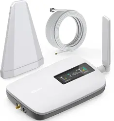
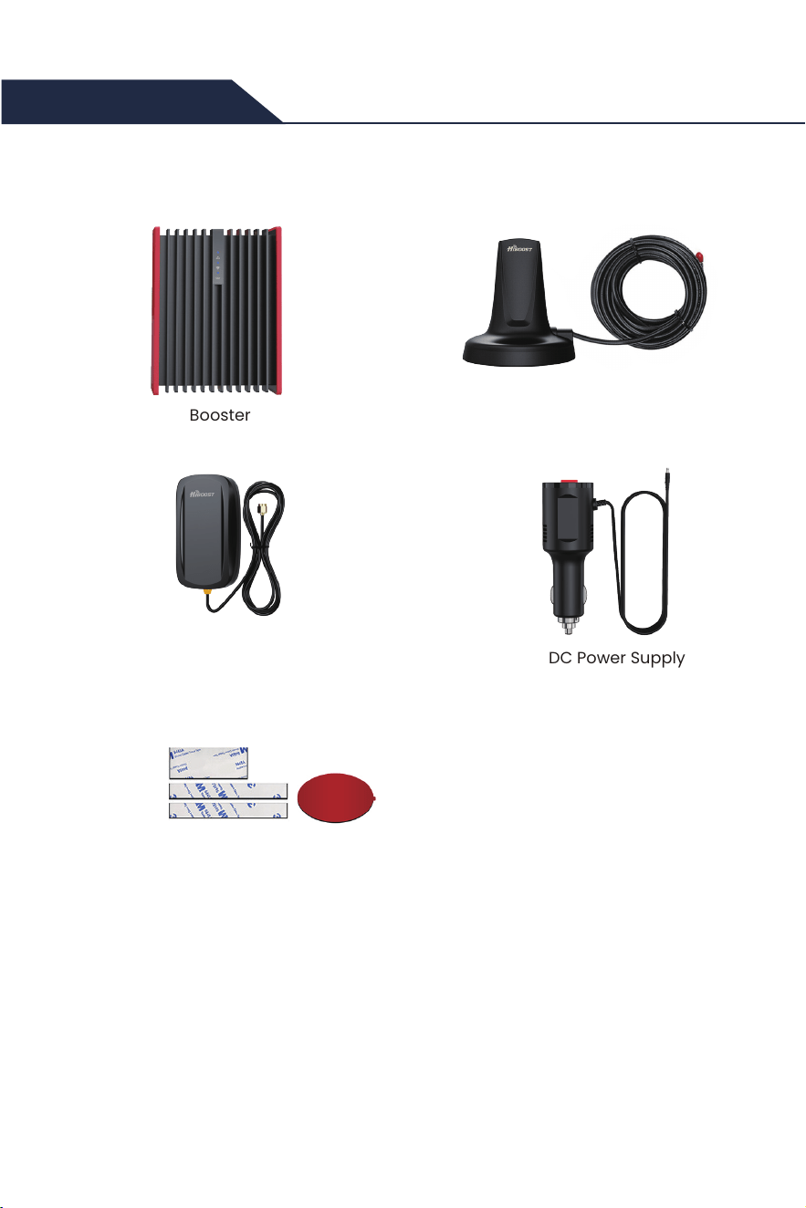
Booster
Travel 3.0 Car
Outside Magnetic Antenna
Inside Panel Antenna DC Power Supply
Other Accessories
to fix the booster and antenna
Warning: Un-authorized antennas, cables, and/or coupling devices are prohibited
by new FCC rules, Please contact FCC for details: 1(888)-CALL-FCC.
Introduction
Thanks again for purchasing HiBoost cell phone booster. The HiBoost vehicle series
is a collection of precision-engineered products that improve cellular reception inside
of vehicles by amplifying incoming and outgoing cell phone signals.
HiBoost cell booster's exclusive cloud-based Signal Supervisor mobile application and
LED indicator allows users to monitor the live status of HiBoost cell phone signal
boosters directly from the LED indicator or remotely from a mobile device anywhere at
any time.
If there are any issues while installing a HiBoost cell phone signal booster, please
contact the HiBoost technical support team through the following options:
(972) 870-5666 (M-F from 9 am – 5 pm CST)
www.hiboost.com
02
Create a ticket or chat via SignalSupervisor app
03
App Introduction
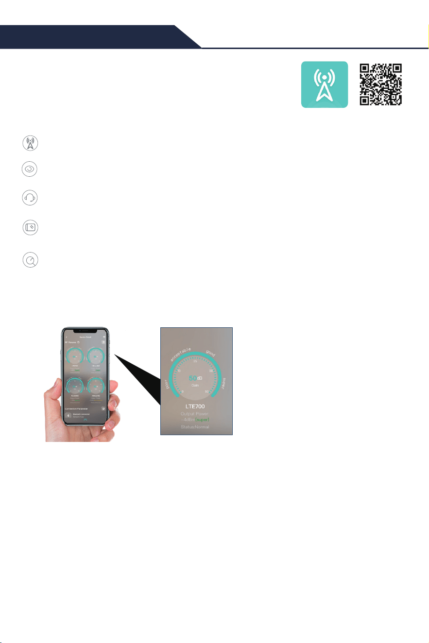
The SignalSupervisor app enables users to view supported
frequency bands and their amplified power data (gain),
ensuring optimal booster configuration.It also offers installation
assistance for quick and accurate setup of the signal booster.
Remote Monitoring: View device status in real-time and remotely switch frequency bands.
Installation Assistance: Maximize device effectiveness by adjusting indoor and outdoor
antennas based on output power changes.
Online Technical Support: Seek technical assistance from customer service via work
orders or online chat.
Community Interaction: Share user experiences, post product reviews, and engage in
interest group discussions.
Documentation Access: Access product specifications and installation videos for
corresponding products (excluding industrial products).
On the device details page of the app, users can view the supported frequency bands,
gain, output power parameters, and check the device's usage status.
Gain: Refers to the degree to which the device amplifies the signal. The higher the gain,
the better the signal transmission distance and quality.
Output Power: Refers to the size of the signal coverage area. The higher the output power,
the greater the coverage area and signal strength.
LTE700: This refers to the frequency band used by the repeater station. For more details,
please refer to the table on page 8.
Coverage Performance: In the app, “Super" indicates that the current repeater station's
coverage performance is satisfactory, with a strong and stable signal; “Good " indicates
that the coverage performance is somewhat lacking and may require adjustment or
optimization to improve signal quality.
Note:The SignalSupervisor app
strictly protects user privacy and
does not collect any personal
information. It is solely used for
viewing device status, assisting with
installation, and obtaining technical
support, without accessing any
personal information from users,
ensuring the security and confidenti-
ality of user data.
1.1 App Functions
1.2 Device Details
04
General Working Principle:
※
Please do spend sometime to read it fully, as it is crucial to get the best performance.
Before we start any of the two ways, please allow us to spend 4 pages to make you
understand how the vehicle booster system works for you.
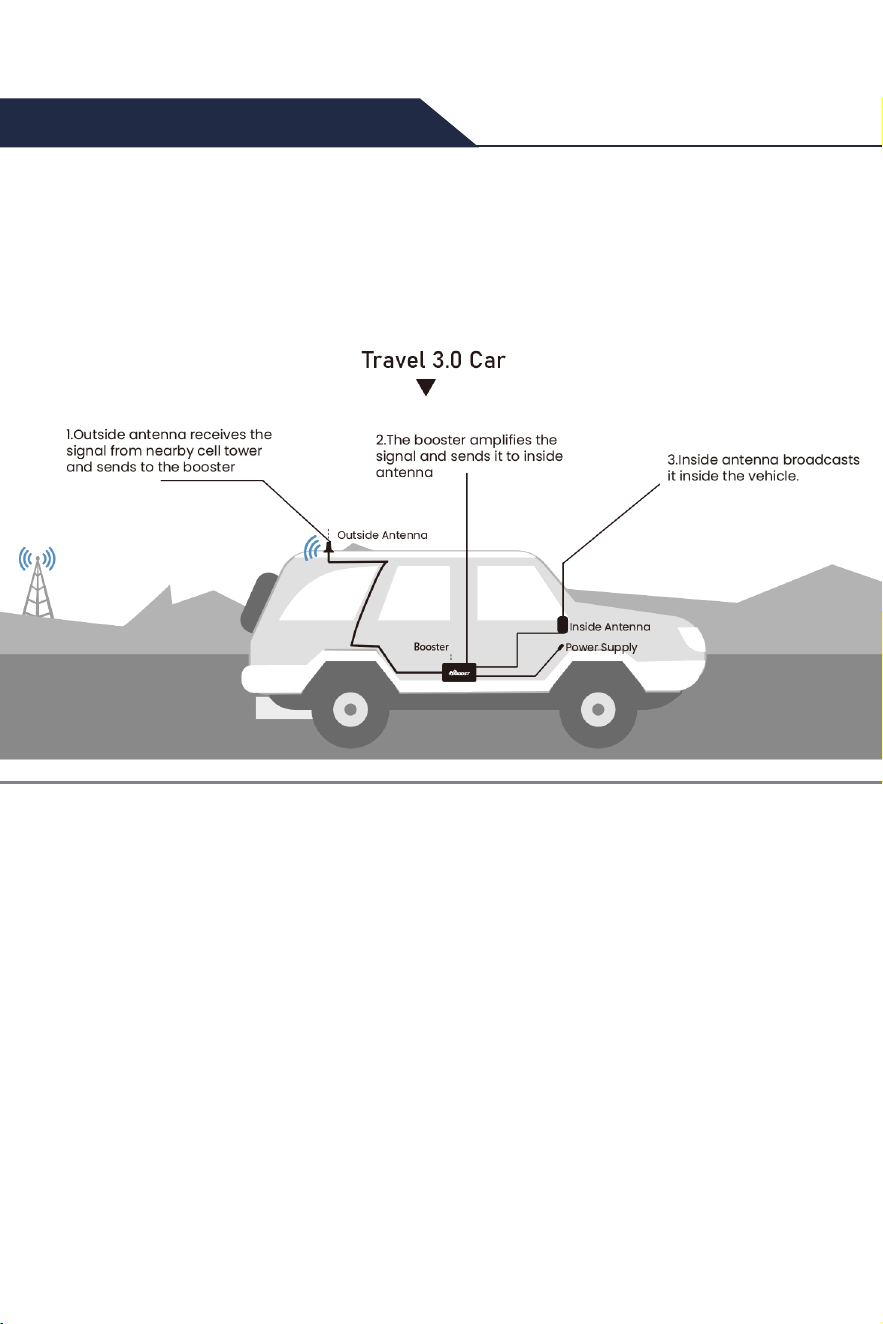
Vice versa, inside antenna receives phone signal and sends to the booster,
The booster then amplifies and sends it to outside antenna,
Outside antenna sends signal to the cell tower.
Then you can make phone calls and do internet streaming.
Travel 3.0 Car
1.Outside antenna receives the
signal from nearby cell tower
and sends to the booster
2.The booster amplifies the
signal and sends it to inside
antenna
3.Inside antenna broadcasts
it inside the vehicle.
Outside Antenna
Inside Antenna
Power Supply
Booster
How HiBoost Booster Works
Note:The indoor antenna installation location shown in the image is for
reference only. During actual installation, the indoor antenna must be
installed at least 0.2 m (20 cm) away from any person.
05
More notes on how to keep the maximum booster gain
※ Please note: This separation is not an absolute mandate. The idea is to
isolate the outdoor antenna from the indoor antenna.
Measures can be taken to avoid the loop back:
1) Increase the distance between outside and inside antennas, generally the same
vertical distance generates more loss than horizontal distance.
2) Use barriers between outside and inside antennas.
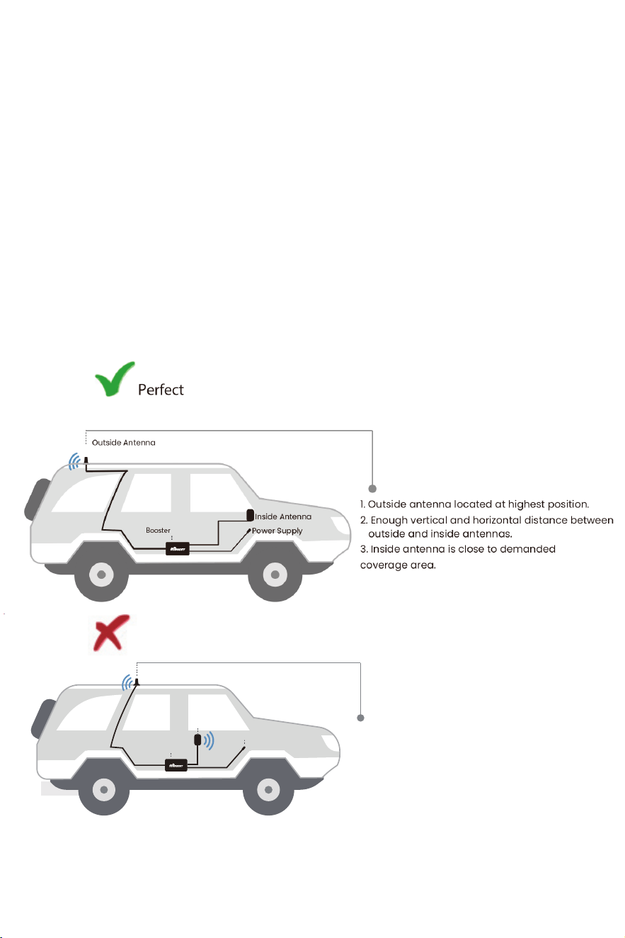
Here are some good and bad solutions for your reference.
The principle is that we need to avoid the loop back between outside and inside
antennas as it reduces the gain.
Outside Antenna
Inside Antenna
Power Supply
Booster
1. Outside antenna located at highest position.
2. Enough vertical and horizontal distance between
outside and inside antennas.
3. Inside antenna is close to demanded
coverage area.
Poor
Perfect
between outside and inside antennas.
1. Not enough horizontal and vertical distance
Outside Antenna
Inside Antenna
Power Supply
Booster
06
You can use third-party software to check the signal strength, supported frequency
bands, and other relevant information in your location, helping to confirm whether the
environment is suitable and if the signal repeater can be used effectively.
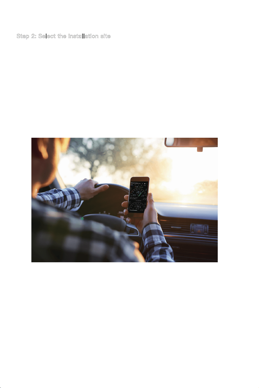
Network Cell Info Lite
OpenSignal
Note:Only supported for Android
Note:Support for Android and iPhone
Flow Chart of App Assisted Installation
App Assisted Installation
Third-party App
Testing Methods of Frequency Band
Signal Detection
BeforeInstallation
Signal Detection Before Installation
1 2 3
Installation Guide
Travel 3.0 Car
Signal Detection After
Installation
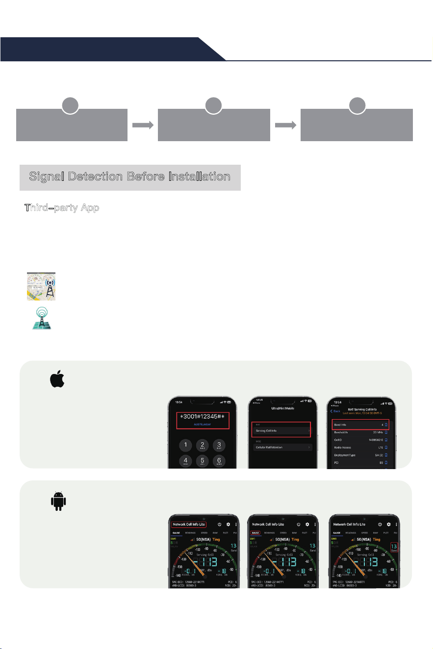
For iPhone
1. Dial *3001#12345#* then
press call button
2. Choose All Metrics,Click
Serving Cell Info
3. Check Band Info
For Android phone
1. Download "Network Cell
Info Lite”
2. Choose"GAUGE"
3. Check"BAND"
07
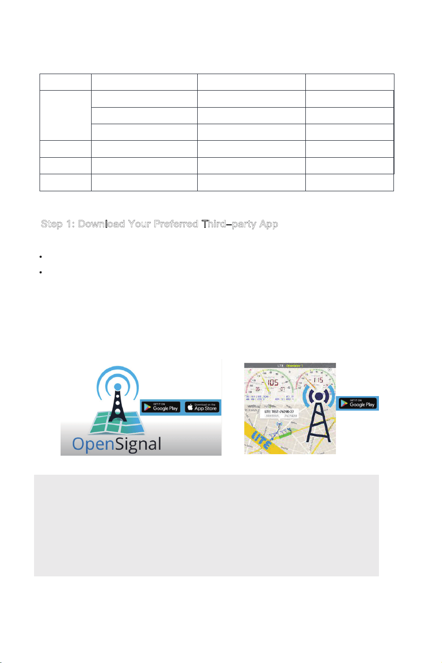
Using a third-party app allows us to:
Find a suitable site to install the booster
Test the signal strength and quality
There are a variety of resources available online: Opensignal,Cell
mapper,
Network cell info lite, etc.
Please download them beforehand over Android and / or iOS:
You can use whichever third-party app that you prefer.
Please download the app of your choice before installing
the booster. In the following instructions, we will show exam-
ples of how using the Network Cell Info Lite app will help with
proper installation of the booster.
Step 1: Download Your Preferred Third-party App
Bands contained in the Gauges on SignalSupervisor
Gauge Band Uplink Downlink
LTE700
CELL800
PCS1900
AWS2100
4 1710-1755MHz 2110-2155MHz
12/17 698-716MHz 728-746MHz
FCC 13
776-787MHz 746-757MHz
5 824-849MHz 869-894MHz
25/2 1850-1915MHz 1930-1995MHz
Please focus on the gauge that contains the band you are using.
ISED 13
777-787MHz 746-756MHz
08
Step 2: Select the installation site
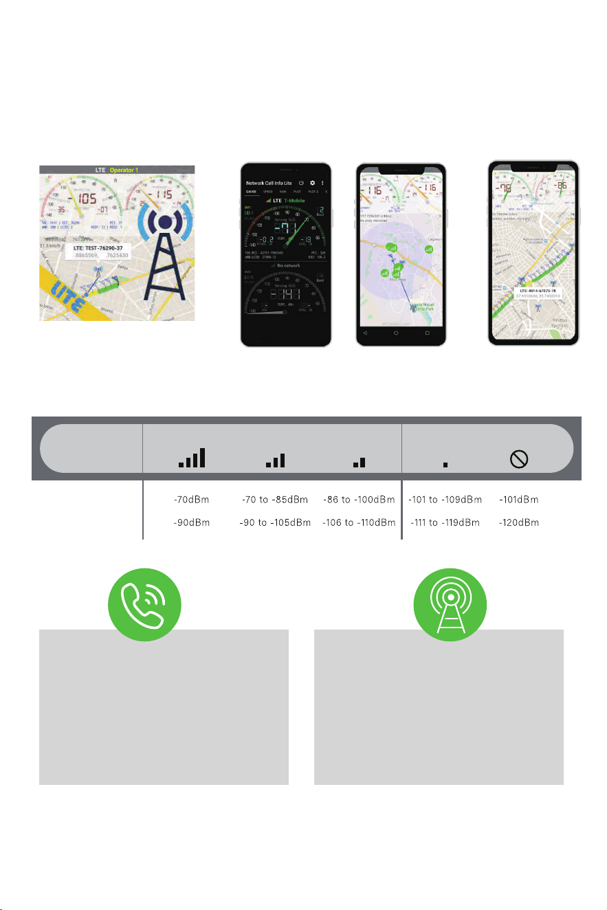
Drive to an area with an outside signal below -85dBm.
The Network Cell Info Lite app will show you your signal as you move around, enabling
you to find this area.
Reasons why a signal strength of less than -85dBm is required:
1) The correct outside signal will create a clean environment for installing the booster
and allow for adjustments that will result in the maximum gain. For example, an outside
signal that is too strong (ex. -40dBm) will reduce the working gain.
2) An area with the correct signal allows the user to test the performance after the
booster has been installed.
09
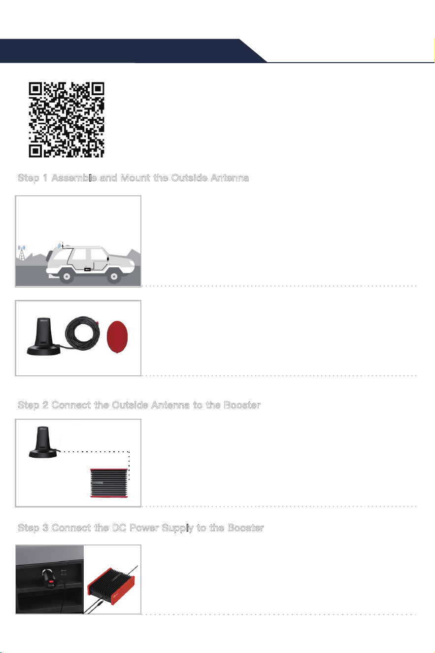
" Network Cell Info Lite " allows users to measure the signal strength before and after
installation, as it shows signal levels. Unfortunately, it is only available for Android devices.
Network Cell Info Lite
The signal strength requested by the booster system is as below.
SIGNAL
STRENGTH
3G/1X
4G/LTE
EXCELLENT
GOOD
FAIR
POOR DEAD ZONE
Signal strength doesn't affect
whether you can make a phone call
or not. However, improved signal
strength will affect the quality of the
phone call, enabling users to hear
each other clearly.
The reason to test your internet
speed is to make sure you'll be able
to stream high-bandwidth movies,
like those from Netflix, Hulu, Amazon,
and other providers. If your internet
speed is too slow, you'll get choppy
video or regular buffering.
10
Getting Started
1.1 Determine where you would like to set up the outside
antenna
1.2 Fix the outside antenna
Usually, the outside antenna is mounted to the roof of the car
near the back.
Note:Please make sure the outside antenna is not placed on the
glass. If you cannot make it, please keep the outside antenna as close
to the back as possible.
The antenna has a built-in magnet. You can fix it directly on
the metal roof or use the double-side tape in the
accessories.
Outside Antenna
Inside Antenna
Power Supply
Booster
Routing the cable into your car and connect it to the booster.
Installation Guide Travel 3.0 Car
Installation Video For Car 3.0
Step 1 Assemble and Mount the Outside Antenna
Step 2 Connect the Outside Antenna to the Booster
Step 3 Connect the DC Power Supply to the Booster
11
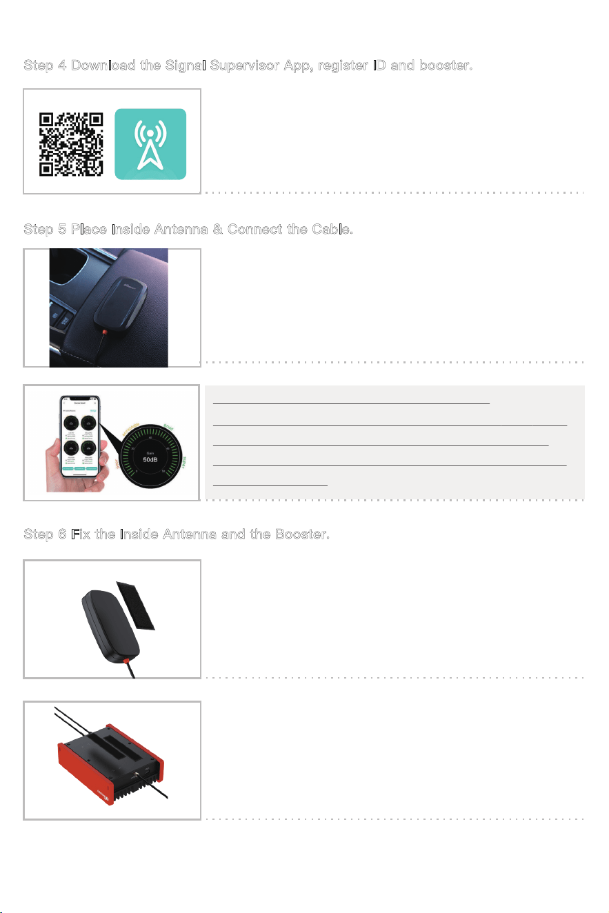
Register an ID first and log in.
Add the booster to the device list.
Use the Signal Supervisor to help installation
The booster will work at best if the gain reaches 50dB. But if
you can’t get so, at least ensure the gain on the gauges
reaches 46~50dB. If not, please kindly adjust the position of
the inside antenna.
Place the inside antenna where you would like to cover signal
and connect it to the booster.
Fix the inside antenna with the provided double-side tape.
Fix the booster with the provided Hook & Loop.
Enjoy your boosted signal!
Step 4 Download the Signal Supervisor App, register ID and booster.
Step 5 Place Inside Antenna & Connect the Cable.
Step 6 Fix the Inside Antenna and the Booster.
12
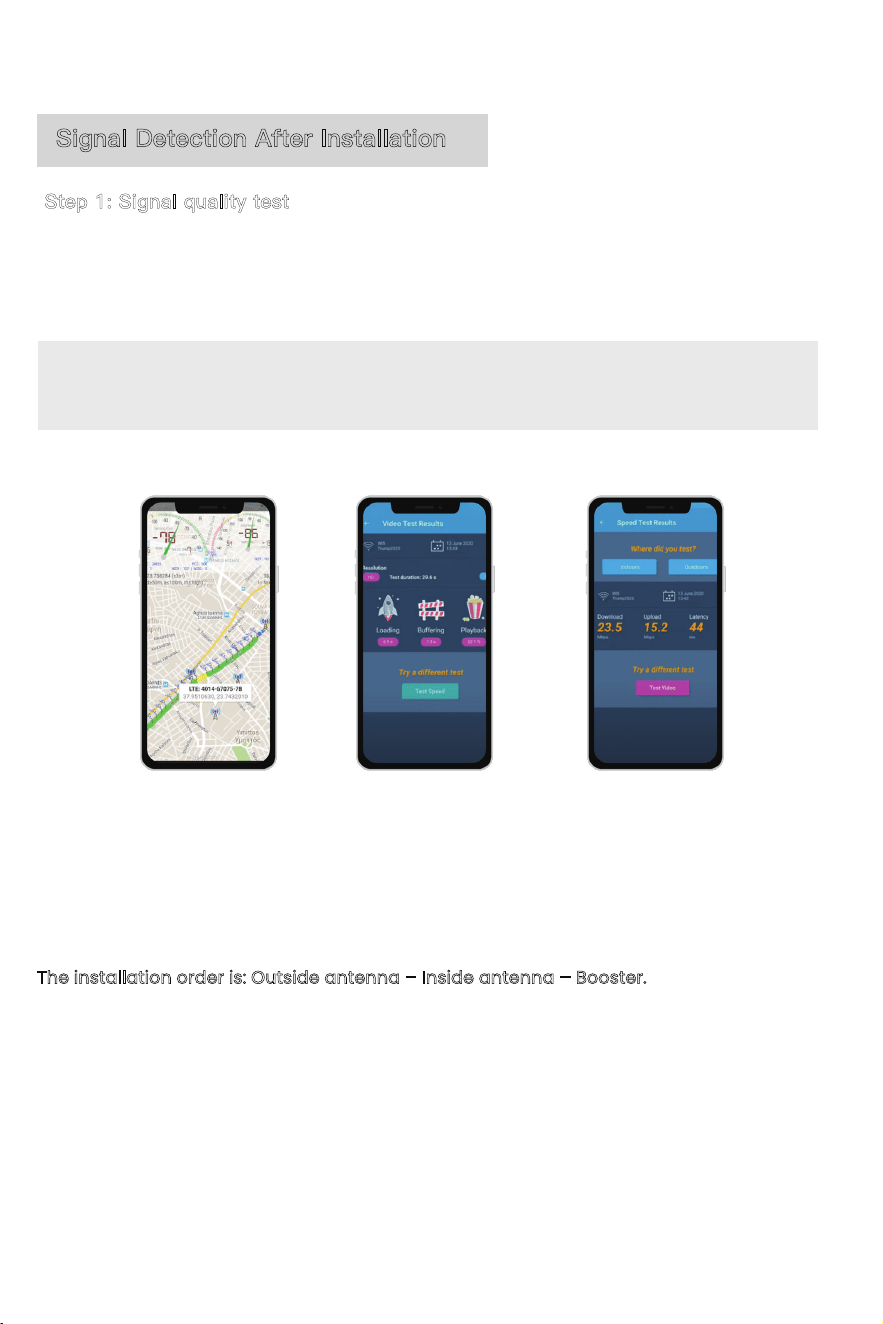
Step 1: Signal quality test
After reaching the MAX possible gain (50dB or as close to 50dB as possible), attach the
outside & inside antennas, then use your device to test phone call and web browsing
capabilities with the third-party app Network Cell Info Lite or OpenSignal.
If the signal quality not ideal, adjust the position of inside or outside antennas, and in the
meantime ensure that the gain remains as high as possible.
When it reaches the ideal test value, the booster, antenna and cable can be firmly
installed.
The installation order is: Outside antenna – Inside antenna – Booster.
Note: Please don't expect the vehicle booster system to be at ideal signal strength in all
areas. The booster gain is limited to 50 dB by the FCC. In addition, the outside signal is
changing at all times while driving, affecting booster gain.
*Notes Again: Just remember that strength and quality are two separate issues. A poor
quality “strong” signal can be next to useless, but a clean signal of two bars might be all
your device needs.
Signal Detection After Installation
13
Step 2: Drive the vehicle to other places to see how it works
Drive the vehicle to various weak areas to test the performance.
Drive the vehicle to various strong areas to test the performance.
Additional Tips
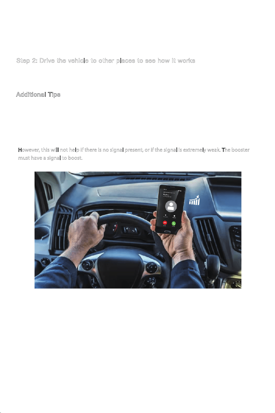
If you travel to an area where the signal is particularly weak and the device cannot be used, press the
inside antenna against the back of the device. This may allow a signal to be obtained. This is not a normal
way to use the booster, but it can help you maintain communication in areas with exceptionally weak
signals.
However, this will not help if there is no signal present, or if the signal is extremely weak. The booster
must have a signal to boost.
14
(972) 870-5666 (M-F from 9 am – 5 pm CST)
www.hiboost.com
If there are any issues while installing a HiBoost cell phone signal booster,
please contact the technical support team through the following channels:
Troubleshooting Guide
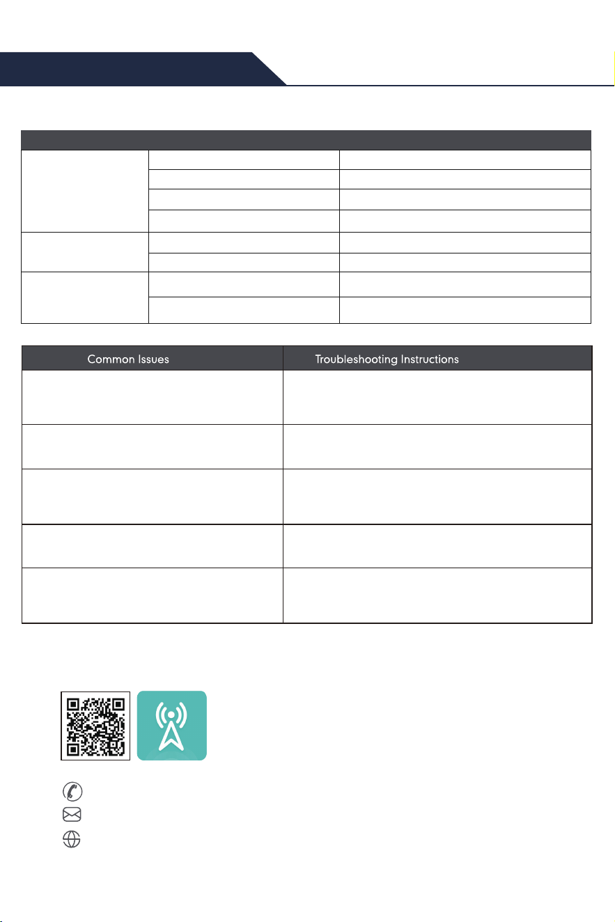
Check that the outside signal is stable by referring
to your mobile device and checking your coverage.
The Alarm LED is quick flashing blue or red
The vehicle booster is installed but there's
still no signal
The signal is not stable after turning on the
booster power
Check to see if the vehicle is started.
Double check connections to make sure none
are loose.
Check to make sure vehicle is not parked too close to
a cell tower.Ensure indoor and outdoor antenna
isolation.
Input voltage is too low(≤10V)/too high(16V~20V)
The Alarm LED is solid red
Check that the booster is turned on and the DC
power outlet is plugged into the DC 12V port or
lighter adapter.
There is No Power
LED STATUS INDICATORS
Bluetooth LED
Wi-Fi LED
Solid blue Wifi disconnected
1s flashing blue Wifi connected
Alarm(ISO) LED
Solid blue Normal
1s flashing blue Slight self-oscillation
0.5s flashing blue
Self-oscillation
Solid red
Solid blue
1s flashing blue
Bluetooth disconnected
Bluetooth connected
Input voltage is not enough
Create a ticket or chat via SignalSupervisor app
15
Technical Specifications
RF Parameter
Electrical Parameter
Mechanical Parameter
Environment Parameter
DownlinkUplink
Frequency Range
Max. Gain
50dB
Max. Power
LTE(A+B)
FCC LTE(C)
CDMA
PCS
AWS
698-716MHz
824-849MHz
1850-1915MHz
1710-1755MHz
728-746MHz
746-757MHz
869-894MHz
1930-1995MHz
2110-2155MHz
Power Supply
Input Impedance
Input DC 9~36V, Output DC 9~36/3A
50 ohms
I/O Port Type SMA-F & RPSMA-M
-10ºC~+55ºC
-10ºC~+80ºC
IP40
Operating Temperature
Storage Temperature
Environment Conditions
ISED LTE(C)
776-787MHz
777-787MHz
746-756MHz
22 dBm
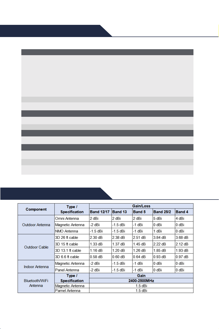
Authorized Accessories List
Note: Unauthorized u
se of accessories (power supplies,
antennas, cables, etc.) is strictly prohibited.
Authorized Accessories List

16
(1) l'appareil nedoit pas produire de brouillage, et
(2) l'utilisateur de l'appareil doit accepter tout brouillage radioélectrique subi,
même si le brouillage est susceptible d'en compromettre le fonctionnement.
IC RF EXPOSURE STATEMENT
The device is compliance with RF exposure limits. The minimum distance
from body to use the device is 20 CM.
Le présent appareil est conforme aux conformité ou aux limites d’inten-sité
de champ RF. La distance minimale du corps à utiliser le dispositif
est de 20 CM.
ISED Warning
This device complies with Innovation, Science, and Economic Develop-
ment Canada licence-exempt RSS standard(s). Operation is subject to
the following two conditions:
(1) this device may not cause interference, and
(2) this device must accept any interference, including interference that
may cause undesired operation of the device.
Le présent appareil est conforme aux CNR d' Innovation, Sciences et Dével-
oppement économique Canada applicables aux appareils radio exempts
de licence. L'exploitation est autorisée aux deux conditions suivantes :
FCC Warning
This device complies with part 15 of the FCC Rules. Operation is subject to the
following two conditions:
(1) This device may not cause harmful interference, and
(2) this device must accept any interference received, including interference
that may cause undesired operation.
FCC and IC Statements
FCC RF EXPOSURE STATEMENT
This equipment complies with FCC radiation exposure limits set forth for an
uncontrolled environment. End users must follow the specific operating
instruction for satisfying RF exposure compliance. This transmitter must not be
colocated or operating in conjunction with any other antenna or transmitter.
This equipment should be installed and operated with minimum distance
20cm between the radiator& your body.

17
FURTHER INFORMATION ON SIGNAL BOOSTER END-USE REGISTRATION
The following links are the currently active contacts for booster registration
with U.S. wireless providers:
https://www.uscellular.com/uscellular/support/fcc-booster-registration.jsp
https://www.sprint.com/legal/fcc_boosters.html
https://www.verizonwireless.com/solutions-and-services/acces-
sories/register-signal-booster/ https://support.t-mo-
bile.com/docs/DOC-9827 https://securec45.securewebsession.com/attsig-
nalbooster.com/
IC Statement: This device complies with Innovation, Science and Economic
Development Canada ICES-003 Compliance Label: CAN ICES-3 (B)/
NMB-3(B). Le présent appareil est conforme Innovation, science et dévelop-
pement économique Canada ICES-003 Étiquette de conformité: CAN ICES-3
(B) / NMB-3 (B).
Please follow the link to access the CPC-2-1-05:
http://www.ic.gc.ca/eic/site/smt-gst.nsf/eng/sf08942.html
This equipment has been tested and found to comply with the limits for a
Class B digital device, pursuant to part 15 of the FCC Rules. These limits are
designed to provide reasonable protection against harmful interference in
a residential installation. This equipment generates, uses and can radiate
radio frequency energy and, if not installed and used in accordance with
the instructions, may cause harmful interference to radio communications.
However, there is no guarantee that interference will not occur in a particu-
lar installation. If this equipment does cause harmful interference to radio
or television reception, which can be determined by turning the equipment
off and on, the user is encouraged to try to correct the interference by one
or more of the following measures:
• Re-orient or relocate the receiving antenna.
• Increase the separation between the equipment and receiver
• Connect the equipment into an outlet on a circuit different from that to
which the receiver is connected
• Consult the dealer or an experienced radio/TV technician for help
Changes or modifications not expressly approved by HiBoost could void
the user’s authority to operate the equipment. For a complete list of
antennas and cables approved for use with these boosters see Authorized
Kitting Options
18
This is a CONSUMER device.
The booster incorporates the following safeguard features to prevent
harmful interference and ensure compliance with the FCC Network Protec-
tion Standard (NPS):
Anti-Oscillation: The booster detects oscillation and automatically reduces
gain or shuts down the affected power amplifier to prevent harmful
interference.
Noise-Power Limiting: The booster monitors RF noise/output power and
automatically adjusts the gain or shuts down the power amplifier when
the applicable noise or power limit is exceeded.
Gain/Power Self-Monitoring: The booster continuously monitors RF operat-
ing conditions and automatically adjusts or shuts down the device when
the applicable limits are exceeded.
Detailed technical implementation and control parameters are provided
in the relevant sections of this Operational Description.
BEFORE USE, you MUST REGISTER THIS DEVICE with your wireless provider and have your
provider’s consent. Most wireless providers consent to the use of signal boosters. Some
providers may not consent to the use of this device on their network.If you are unsure,
contact your provider.
In Canada, BEFORE USE, you must meet all requirements set out in ISED CPC-2-1-05.
You MUST operate this device with approved antennas and cables as specified by the
manufacturer. Antennas MUST be installed least 20 cm(8 inches)from(i. e..MUST NOT be
installed within 20 cm of)any person.
You MUST cease operating this device immediately if requested by the FCC(or ISED in
Canada)or a licensed wireless service provider.
WARNING. E911 location information may not be provided or may be inaccurate for calls
served by using this device.

30-Day Money-Back Guarantee: If for any reason the performance of any
product is not acceptable, the product may be returned to the reseller within
30-days with proof of purchase. Please contact the customer support team.
3-Year Warranty: Signal boosters and kits are warranted for 3 years. We will
repair or replace the unit and will cover the cost of delivery back to consumers
located within the continental US and Canada. We will only cover shipping to
our office if the booster was delivered to you recently, and was delivered
defective.Damage caused by the use of non-company power supplies or
other accessories is not covered under warranty.
Customers can choose to return the signal boosters and kits directly to the
manufacturer at the purchaser's expense with a dated proof of purchase and a
Returned Material Authorization (RMA) number supplied by us. RMA numbers
may be obtained by contacting customer support at 972-870- 5666 or support
@hiboost.com
This warranty does not apply to any signal boosters or kits determined by us
to have been subjected to tampering, misuse, abuse, neglect, or mishandling
that alters or damages physical or electronic properties.
We are not liable for any Signal Supervisor application network connectivity
issues. The cell phone signal booster relies on a strong, continuous and reliable
connection to the internet in order to communicate with the cell phone appli-
cation. For all Signal Supervisor Application related issues, please check your
network strength and call our technical support.
Failure to use a surge-protected AC power strip with at least a 1000 Joule
rating will void your warranty. Damage caused by lightning is not covered by
this warranty.
All of the products that are packaged with other accessory products are
intended for resale and used as a single integrated system. Such product kits
are required to be sold to the end-users or subsequent reseller as packaged.
Return and Warranty Policies
19