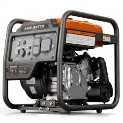
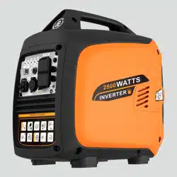
INVERTER GENERATOR
Please read and save this manual.

1
Be sure to read the manual before using, otherwise the wrong operation will
lead to safety risks or equipment damage. As long as follow the operation of this
manual book, the company's inverter generator is safe and reliable.
Safety Warning
The personal and property safety of you and others is very important. Please
read carefully the extremely important safety warnings we have written in the
manual and the label of the generator set.
Safety warnings can alert you to potential hazards that could harm you and
others.
Each safety warning is preceded by one of the three words "DANGER,"
"WARNING" or "CAUTION". Details are as follows:
If you do not follow the instructions, your life will be in danger or you will be
seriously injured.
If you do not follow the instructions, your life could be in danger or you could be
seriously injured.
If you do not follow the instructions, you will be slightly injured.
If you do not follow the instructions, your generator set and other property may be
damaged.

2
Contents
1. Safety Instruction
.......................................................................................... 3
2. Safety Warning Label
................................................................................... 5
3. Components Identification...........................................................................6
4. Control System
...............................................................................................8
5. Preparation
................................................................................................... 11
6. Generator Use..............................................................................................14
7. Starting the Generator
................................................................................18
8. Stopping the Generator
............................................................................. 19
9. Maintenance.................................................................................................19
10. Storing
......................................................................................................... 24
11. Trouble Shooting
.......................................................................................25
12. Circuit Diagram..........................................................................................26
13. Technical Specifications
..........................................................................27
14.
SERVICE INFORMATION
......................................................................28

3
1. Safety Instruction
1.1 Safety Specification
Please read and be well known about the manual before operating.
Familiarity with the safe operating procedures of generators can help
you avoid accidents.
Don’t use it indoor.
Don’t use it in damp environment.
Products without ATS(Automatic
Transfer Switch) function should not
be directly connected to the
household power grid.
Don’t smoke while adding fuel oil.

4
Do not spill oil when fueling.
Please stop running before fueling.
Please remove the combustible materials away at least 1m.
1.2 Special Request
Electrical equipment includes unexposed wires and plugs.
The protecting breaker should be matched with generator. The
application parameters and performance should be totally
matched if changing.
Well grounded before using.
If need extension wire, it must meet the requests as below:
4mm
2
,length no more than 100m.

5
2. Safety Warning Label
Please read the instruction manual carefully before use.
Warning; hot surface. Taking care to avoid coming into contact
with a hot surface.
Gasoline is flammable and explosive, please use it outdoors.
Before adding gasoline, stop the engine and keep away from
sources of ignition. Please add gasoline outdoors.
Exhaust gas contains carbon monoxide, it is strictly prohibited to
use in indoor and closed environment. [Carbon monoxide(CO)
danger].
A generator that is not kept dry is a potential cause of electric
shock. Do not expose the generator to damp, rain or snow.
Never operate the generator with wet hands.
Let the generator cool before storing. Gasoline is explosive
and flammable. Please use the generator outdoor.
Do not connect to a building's electrical system.
Please read the instruction manual carefully before use.

6
3. Components Identification
3.1 Components Feature

7
3.2 Control Panel
(Factory will adjust the panel according to different configuration.
Please note that subject to change without prior notice.)
1 Engine Switch
2 ECO Switch
3 Low Oil Indicator (yellow)
4 Overload Indicator (red)
5 Running Indicator (green)
6 AC RESET
7 USB Socket
8 AC1 Overload
9 AC2 Overload
10 AC1 Socket
11 AC2 Socket
12 Ground Terminal

8
4. Control System
4.1 Engine Oil Alerting System(YELLOW)
The engine oil protection system will stop the engine
automatically, and the engine oil indicating lights,
while the oil in crankcase is under safe line. Fill the
engine oil to the oil level, it can be restart again.
If the engine oil alerting light flashes for few seconds, it means the oil
capacity is insufficient. Refill the oil and restart the engine.
4.2 Overload Indicating Light(RED)
4.2.1 When the red indicator light flashes and
the green indicator light remains on constantly, it
indicates that the generator set has exceeded the
rated load. If used for a long time, the output will
be automatically disconnected. Please reduce the
load equipment or lower the load power to the rated power range.
4.2.2 When the green indicator light goes out and the red indicator
light flashes 6 times every 3 seconds, it indicates that the output of the
generator set is disconnected due to overload protection or short circuit.
Please reduce the load equipment or lower the load power to the rated
power range, or remove the short circuit fault, and then gently touch the AC
reset button. When the green indicator light is on again, it indicates that the
generator set is operating normally.
4.2.3 When the green indicator light is off and the red indicator flashes
3 times every 3s, it indicates that the operating temperature of the

9
generator set has exceeded the limit. Please turn off the generator set and
place it in a well-ventilated environment with a temperature below 40
℃
before using it again. Or reduce the load power and then gently touch the
reset button. When the green indicator light is on again, it indicates that the
generator set is operating normally.
4.2.4 When the green indicator light is off and the red indicator light
flashes once every 3s, it indicates that the power input of the generator set
is insufficient. Please turn off the generator set, maintain the air filter, spark
plug and carburetor before using it again. Or reduce the load power and
then gently touch the reset button. When the green indicator light is on
again, it indicates that the generator set is operating normally.
NOTE: When using the electrical equipment with high starting
current (like compressors and sinking pumps,etc.), the overload
indicator may flash for few seconds, which is a normal phenomenon,
because the inverter is controlled according to the current, as long as
the duration does not reach the protection time, the equipment will
return to normal after successful operation.
4.3 AC Indicating Light(GREEN)
The AC indicating light will be on while
the engine starts and keep normal
output.

10
4.4 ECO Switch
4.4.1 “ON”
When the switch is in the "ON" position, the
energy-saving device controls the engine speed
according to the load it is connected to, resulting in
better fuel consumption and low noise.
4.4.2 “OFF”
When the energy-saving switch is in the "OFF" position, the engine
runs at rated speed regardless of whether the load is connected.
NOTE: When using devices such as air compressors or sinking
pumps, the ECO must be turned off as a large starting current is
required.
4.5 Ground Terminal
The ground terminal is connected to the ground wire to prevent electric
shock. When electrical equipment is grounded, the generator must be
grounded.
Ground terminal

11
5. Preparation
5.1Check fuel
Under certain circumstances, gasoline is extremely flammable
and explosive.
Please refuel in a well-ventilated place and shut down the engine.
Smoking or open flames are prohibited in the engine refuelling area and
gasoline storage area.
Don't overfill the fuel or it will overflow as the tank gets hot (the
fuel level is lower than the red level indicator). After refuelling, make
sure that the fuel tank cap is tightened (when there is a "click" sound).
After refuelling, dry the remaining gasoline with a piece of clean
and soft cloth.
Avoid prolonged, repeated contact with gasoline or inhalation of
gasoline vapor.
Do not allow children to touch gasoline.
You must use unleaded gasoline. The leaded one would damage the
internal parts of the engine.
Suggestion: unleaded gasoline

12
5.2 Check oil level
5.3 Starter Handle
Pull the starter handle up gently until resistance is felt, then pull it out
suddenly.
The generator was delivered without engine oil. Do not start the
generator without sufficient engine oil.
Use a high-quality 4-stroke engine oil that meets or exceeds API
classification SJ (American
Petroleum Institute) as required by
American automobile manufacturers.
SAE 10W-30 is
the recommended
lubricant for the generator set under
common temperature conditions.
Other viscosity grades may be used if the average temperature in your
area falls within the range shown in the chart.

13
After starting, please do not let the starting handle spring back suddenly,
but gently put the handle back.
5.4 Fuel Tap
Fuel tap is a device that controls the flow of fuel from the tank to the
carburetor. Please make sure it is on position of “OFF” after stop working.
5.5 Ground Terminal
Before using the generator, make sure that the ground terminal is securely
connected to the ground.
Ground Terminal
OFF
ON

14
5.6 AC circuit breaker
When the current is overloaded, the AC output is automatically cut off,
which can effectively protect the AC output sockets or AC electrical
devices.
Prevent the occurrence of short circuits and overloads. Before
reactivating the circuit breaker, it is essential to check the load condition.
5.7 Choke Valve Handle
When the choke valve handle is set to the "ON" position, the choke
valve of the carburetor is in the open state, ensuring that the carburetor has
sufficient air intake for normal operation. This is suitable for restarting a
warm engine, or initial startup and generator operation when the ambient
temperature is high. When the choke valve handle is set to the "OFF"
position, the carburetor choke is in the closed state, which is suitable for
cold engine starting.
6. Generator Use
Applicable temperature:-5
℃
~40
℃
Applicable humidity :below 95%
Applicable altitude: below 1000m (In areas above 1000 meters, the
AC circuit breaker

15
power should be reduced or contact the dealer to adjust the carburetor.)
6.1 Connect Household Electrical Equipment
After connecting the household electrical equipment to the
generator, carefully check whether the electrical connection is safe
and reliable. If there is an incorrect electrical connection, it may
cause damage to the generator, catch fire or cause a fire.
When connecting the generator to the household power grid as a
backup power , it should be operated by a specialist electrician or
someone familiar with electricity.
Generator without ATS (Automatic Transfer Switch) function
should not be directly connected to the household power grid.
OK
OK
NO

16
6.2 Generator Grounded
In order to prevent electrical appliances from being damaged by electric
shock or the wrong use of electricity, it is recommended to connect the
generator to the ground using high-quality insulated wire before using it.
6.3 AC Output
Before starting the generator, please confirm:
The total power of the load appliances (the sum of the resistive, capacitive
and inductive loads) shall not exceed the rated power of the generator.
Overloading will cause the generator to shut down or
significantly shorten its lifespan. If the generator is connected with
several loads or electric equipment, please remember: First connect
the one with the highest starting load, and finally connect the one
with the lowest starting current.
Ground terminal

17
Generally speaking, capacitive and inductive loads, especially motor
drives, produce a large starting current during starting. The following table
is for your reference when connecting these electrical appliances to the
generator set.
Type
Wattage
Typical
Equipment
Example
Start
Rated
Device
Start
Rated
●Incandescent
Lamp
●Heating
Apparatus
X1
X1
100W
100VA
(W)
100VA
(W)
●Fluorescent
Lamp
X2
X1.5
40W
80VA
(W)
60VA
(W)
●Electromotor
Drive Device
X3-5
X2
150W
450-750VA
(W)
300VA
(W)
6.4 Used in High Altitude Areas
At high altitudes, a standard carburetor will make the gasoline engine
mixture too strong, reduce the output power and increase the fuel
consumption rate. The performance of a gasoline engine can be improved
by replacing the carburetor with a smaller main nozzle or by adjusting the
adjusting screw. If you always use the generator at high altitudes among
1000m from sea level, you can come to our authorized dealer to replace a
carburetor. Otherwise, the load power should be reduced by using the

18
generator.
Even with the right carburetor, each 300m rise in altitude reduces the
power of a gasoline engine by about 3.5%. This decline would have been
greater if the carburetor had not been replaced properly.
If the carburetor suitable for high-altitude use is equipped with the
gasoline engine suitable for low-altitude use, the thin mixture will
cause the output power of the gasoline engine to drop, overheat and
even cause serious damage.
7. Starting the Generator
7.1 Recoil Start
1) Check the engine oil and fuel level before starting, and remove all
loads from the output end.
2) Put Engine Switch in the “ON” position.
3) Put Fuel Tap in the “ON” position.
4) Put the AC Circuit Breaker in the “OFF” position.
5) Put the Choke Valve Handle in the “OFF” position when start in a cold
state.
When starting the engine in a hot state, please set the Choke Valve
Handle to the “ON” position.
6) Pull the starter handle up gently until you feel resistance and pull it
out quickly.
7) When the generator is started, place the choke valve handle in the

19
“ON” position.
8) Put the AC Circuit Breaker in “ON” position before using the electrical
load.
8. Stopping the Generator
1)Disconnect all electrical equipment.
2)Turn off the ECO switch.
3)Turn off AC Circuit Breaker.
4)Turn off the Engine Switch.
5)Turn off the Fuel Tap.
To stop the generator in an emergency, put the generator switch in
the "OFF" position.
9. Maintenance
Good maintenance is the best guarantee for safe, economical and
zero fault operation, also contribute to environment protection.
In order to keep the engine in good condition, you must check and
maintain it regularly. Please follow the schedule below.
Maintenance period
Item
Each
use
First
month
or
20 hrs
Every 3
months
or 50 hrs
Every
year
Engine oil
Check-Refill
√
Replace
√
√
Gearbox gear
oil (If any)
Check oil
level
√
Replace
√
√
Air filter
element
Check
√
Clean
√

20
The engine oil should be replaced every 10 hours if working
frequently at high temperatures or loads.
The air filter element should be cleaned every 10 hours if working
frequently at dusty or bad environment.If necessary, please replace it
every 25 hours.
The inspection cycle and time should follow a first-come, first-served
maintenance schedule.
If the maintenance cycle time has passed, the maintenance should be
carried out as soon as possible according to the above table.
Replace
√
Precipitation
cup (if any)
Clean
√
Spark plug
Check-Adjust
√*
Spark arrester
Clean
√
√
Idle (if any)**
Check-Adjust
√
Valve
clearance**
Check-Adjust
√
Fuel tank &
filter**
Clean
√
Fuel oil pipe
Check
Every 1 years
(
Please replace it if
necessary.)
Cylinder head,
Piston
Remove
carbon
deposition**
Displacement < 225cc
,
every 125 hrs;
Displacement ≧225cc,every 250 hrs.
* These items should be replaced if necessary.
** These items should be maintained by our authorized dealers unless the user
has the appropriate tools and repair capacity.

21
Please stop the generator before any maintenance. Place it in a
horizontal position. To prevent engine starting, separate the spark
plug cap from the spark plug.
Please do not use it indoors or or in places with poor ventilation
such as tunnels and caves. Make sure the working area is well
ventilated. Exhaust from engines contains the toxic gas carbon
monoxide, which can cause shock, loss of consciousness and even
death when inhaled.
9.1 Replace Engine Oil
Starting the gasoline engine for a few seconds and then stopping it
can ensure the oil is discharged quickly and cleanly.
① Remove the oil dipstick. Unscrew the drain bolt to drain oil.
② Install the drain bolt and tighten it.
③ Fill oil and check oil level.
④ Install the oil dipstick.
Prolonged and frequent exposure to oil can lead to skin cancer. While
this is not a given, it is still recommended that you use soap and water to
immediately and thoroughly wash any skin that has been exposed to oil.
From an environmental point of view, please properly handle the
waste oil produced after use. We strongly recommend that you put the oil
in a sealed container and take it to your local service station or oil recycling
center. Please remember: don't throw it in the trash or dump it on the
ground or in a ditch.

22
9.2 Air Filter Maintenance
Dirty air filters will affect the flow of air into carburetors. To prevent
carburetor breakdown, air filters should be regularly maintained. If it is used
in dusty environment, it should be maintained more frequently.
Cleaning the filter element with gasoline or flammable solvents may cause
fire or explosion. Please use soapy water or non-flammable solvent to
clean the filter element.
It is strictly forbidden to start the generator without air filter, otherwise it will
lead to rapid wear and tear of the gasoline engine.
1
)
Open the locking bolt of the air filter cover and open the air filter cover.
Check the filter element and ensure it’s in good condition and clean
。
2 ) If the foam filter is dirty, please clean it. Wash in hot water with
household detergent or in non-flammable or high flash solvent. Then rinse
with clean water and squeeze. Then drop a few drops of oil and squeeze
evenly.
3
)
Fill in the filter element and cover the air filter cover, then tighten the
locking bolt.
Foam Filter
Air Filter Cover
Locking Bolt

23
9.3 Spark Plug
To ensure the normal operation of the generator set, the spark plug
gap must be adjusted correctly and carbon deposits must be removed.
Incorrect spark plug can cause engine damage. If the engine is hot,
please wait until it cools down to maintain the spark plug, and replace the
spark plug according to the original spark plug model: F7TC/ F7RTC.
1
)
Remove the spark plug cap.
2
)
Use the spark plug socket wrench to remove the spark plug.
3) Visually inspect whether the spark plug insulator is damaged.
Replace the spark plug if it is damaged.
4
)
Measure spark plug clearance with thickness gauge. Bend the
side electrodes to adjust the clearance.The clearance shall be
between 0.70 and 0.80mm.
5) Check that if the spark plug gasket is in good condition. To
prevent the threads from stripping, carefully screw the spark plug
back in by hand.
6) After reinstalling the spark plug, use a spark plug socket to tighten
it. And press down the spark plug gasket.
7) Cover the spark plug cap.
Please use spark plugs with appropriate calorific value.

24
10. Storing
To avoid combustion or misfire due to contact with high-temperature
components of the generator, the generator must be cooled before
packaging and storage.
If long-term storage is required, please make sure the storage area is
clean and dry.
1) Drain fuel from the fuel tank. Clean the fuel filter, O-ring seal and
precipitation cup after the assembly. Unscrew the carburetor drain bolt,
drain the fuel from the carburetor entirely, then reinstall and tighten the
carburetor drain bolt.
In ordinary circumstances, gasoline is flammable and explosive.
Please discharge oil in well-ventilated condition after stop. No
fireworks during oil discharge.
2
)
Unscrew the oil dipstick and oil drain bolt on the crankcase, and drain
the oil in the crankcase. Then tighten the drain bolts, add new oil to the
upper limit, and then install the oil dipstick.
3) Remove the spark plug and pour a tablespoon of clean engine oil into
the combustion chamber. Turn the crankshaft several times to distribute
the oil. Reinstall the spark plugs.
4) Gently pull the starting handle until resistance is felt, leaving the inlet
and exhaust doors close.
5) Place the generator set in a clean and dry area.

25
11. Trouble Shooting
When the engine cannot be started:
When it shows no voltage:
Yes
No
No
Check if there is any fuel
in the fuel tank?
Check if there is enough
engine oil in the crankcase?
Add oil
Add fuel
Yes
Check if there is any fuel in
the carburetor?
Check if the spark plug is in
good condition?
No
Ask the authorized
repair center for
service
Change the
spark plug
No
Yes
Check and clean
the carburetor
sedimentation cup
Yes
Ask the authorized repair
center for service
Is the circuit breaker
protector turned on?
Yes
Turn on the circuit
breaker protector
Check if there are any
faults with the electrical
components?
No
No
Ask the authorized
repair center for service
Change the electrical
components
Yes
No

26
12. Circuit Diagram
(The factory will adjust according to the different configuration, subject to
change without prior notice.
)

27
13. Technical Specifications
Item
EDOG21
Gasoline
engine
Engine type
Single cylinder, four-stroke, air-cooled
Displacement(cc)
223
Starting type
Recoil start
Fuel tank capacity (L)
13L
Engine oil capacity(L)
0.6
Generator
set
Rated frequency(Hz)
60
Phase
Single
Rated voltage (V)
120
Rated output power(kW)
4.5
Max. output power (kW)
6
THD without load
≤5%
Running time at rated
power·h
≥3.5
Weight(kg)
33
Dimensions(mm)
455×420×491

28
14. SERVICE INFORMATION
If you are not entirely satisfied with your purchase,please feel free to contact us
using the following steps:
1. Go to Your Orders.
2. Find your order in the list.
3. Select Problem with order
4. Choose your topic from list displayed.
5. Select Contact seller.
6. You can also contact us via email, our email:
InGeneratorSupport@163.com

EMISSION CONTROL SYSTEM WARRANTY STATEMENT
YOUR WARRANTY RIGHTS AND OBLIGATIONS
The U. S. EPA and STAR SKY TECHNOLOGY INTERNATIONAL GROUP CO.,LTD are pleased
to explain the emissions control system warranty on your model year 2026 and later small
off-road engine and equipment (equipment).
New equipment must be designed, built and equipped to meet the stringent anti-smog standards.
STAR SKY TECHNOLOGY INTERNATIONAL GROUP CO.,LTD must warranty the emission control
system on your equipment for the period of time listed below, provided there has been no
abuse, neglect or improper maintenance of your equipment.
Your emission control system may include parts such as the carburetor, air cleaner, ignition system,
exhaust system, and other associated emission-related components.
Where a warrantable condition exists, STAR SKY TECHNOLOGY INTERNATIONAL GROUP CO.,LTD
will repair your equipment at no cost to your including diagnosis, parts and labor.
MANUFACTURER’S WARRANTY COVERAGE
This emissions control system is warranted for two years. If any emission-related part on your equipment
is defective, the part will be repaired or replaced by STAR SKY TECHNOLOGY INTERNATIONAL
GROUP CO.,LTD.
OWNER’S WARRANTY RESPONSIBILITIES
As the equipment owner, you are responsible for the performance of the required maintenance listed in
your Owner’s Manual. STAR SKY TECHNOLOGY INTERNATIONAL GROUP CO.,LTD recommends that
you retain all your receipts covering maintenances on your equipment, but STAR SKY TECHNOLOGY
INTERNATIONAL GROUP CO.,LTD cannot deny warranty solely for the lack of receipts or for your failure
to ensure the performance to all scheduled maintenance.
As the equipment owner, you should however be aware that STAR SKY TECHNOLOGY
INTERNATIONAL GROUP CO.,LTD may deny your warranty coverage if your equipment or part has
failed due to abuse, neglect, improper maintenance or unapproved modifications.
You are responsible for presenting your equipment to an Authorized STAR
SKY TECHNOLOGY INTERNATIONAL GROUP CO.,LTD Service Dealer as soon as a
problem exists. The warranted repairs should be completed in a reasonable amount of time, not
to exceed 30 days.
If you have any questions regarding your warranty rights and responsibilities, you should contact:
Company: Windrider Tech Co., Ltd.
Contact Person:Austin
Tel.: 3322586131
Mail: [email protected]
Add.: 2707 Realty Road STE 100 Carrollton Texas 75006

DEFECTS WARRANTY REQUIREMENTS
STAR SKY TECHNOLOGY INTERNATIONAL GROUP CO.,LTD warrants to the ultimate purchaser and
each subsequent purchaser that the equipment is designed, built and equipped so as to conform with all
applicable regulations; and free from defects in materials and workmanship that cause the failure of a
warranted part, and is identical in all material respects to that part as described in the application for
certification.
The warranty period begins on the date the equipment is delivered to an ultimate purchaser or first placed
into service. Subject to certain conditions and exclusions as stated below, the warranty on emission-
related parts is as follows:
1.
Any warranted part that is not scheduled for replacement as required maintenance in the written
instructions supplied is warranted for the warranty period stated above. If the part fails during the period of
warranty coverage, the part will be repaired or replaced by STAR SKY TECHNOLOGY INTERNATIONAL
GROUP CO.,LTD according to subsection (4) below. Any such part repaired or replaced under warranty
will be warranted for the remainder of the period.
2.
Any warranted part that is scheduled only for regular inspection in the written instructions supplied is
warranted for the warranty period stated above. Any such part repaired or replaced under warranty will be
warranted for the remaining warranty period.
3.
Any warranted part that is scheduled for replacement as required maintenance in the written instructions
supplied is warranted for the period of time before the first scheduled replacement date for that part. If the
part fails before the first scheduled replacement, the part will be repaired or replaced by STAR SKY
TECHNOLOGY INTERNATIONAL GROUP CO.,LTD according to subsection (4) below. Any such part
repaired or replaced under warranty will be warranted for the remainder of the period prior to the first
scheduled replacement point for the part.
4.
Repair or replacement of any warranted part under the warranty provisions herein must be performed at a
warranty station at no charge to the owner.
5.
Notwithstanding the provisions herein, warranty services or repairs will be provided at all of our distribution
centers that are franchised to service the subject engines or equipment.
6.
The equipment owner will not be charged for diagnostic labor that is directly associated with diagnosis of a
defective, emission-related warranted part, provided that such diagnostic work is performed at a warranty
station.
7.
STAR SKY TECHNOLOGY INTERNATIONAL GROUP CO.,LTD is liable for damages to other engine or
equipment components proximately caused by a failure under warranty of any warranted part.
8.
Throughout the equipment warranty period stated above, STAR SKY TECHNOLOGY INTERNATIONAL
GROUP CO.,LTD will maintain a supply of warranted parts sufficient to meet the expected demand for
such parts.
9.
Any replacement part may be used in the performance of any warranty maintenance or repairs and must
be provided without charge to the owner. Such use will not reduce the warranty obligations of STAR SKY
TECHNOLOGY INTERNATIONAL GROUP CO.,LTD.
10.
Add-on or modified parts that are not exempted by the Air Resources Board may not be used. The use of
any non-exempted add-on or modified parts by the ultimate purchaser will be grounds for disallowing a
warranty claim. STAR SKY TECHNOLOGY INTERNATIONAL GROUP CO.,LTD will not be liable to
warrant failures of warranted parts caused by the use of a non-exempted add-on or modified part.

WARRANTED PARTS
The repair or replacement of any warranted part otherwise eligible for warranty coverage may be
excluded from such warranty coverage if STAR SKY TECHNOLOGY INTERNATIONAL GROUP
CO.,LTD demonstrates that the equipment has been abused, neglected, or improperly maintained,
and that such abuse, neglect, or improper maintenance was the direct cause of the need for repair
or replacement of the part. That notwithstanding, any adjustment of a component that has a factory
installed, and properly operating, adjustment limiting device is still eligible for warranty coverage.
Further, the coverage under this warranty extends only to parts that were present on the equipment
purchased.
The following emission warranty parts are covered (if applicable):
1.
Air-induction system
. • Air cleaner
. • Intake manifold
2.
Fuel system
. • Cold start enrichment system (soft choke)
. • Carburetor and internal parts
. • Fuel Pump
. • Fuel Tank
3.
Ignition system
. • Spark plug(s)
. • Magneto Ignition System
4.
Exhaust systems
5.
Miscellaneous Items Used in Above System
. • Vacuum, temperature , position, time sensitive valves and switches
. • Sensors
. • Electronic control units
6.
Evaporative Emissions Control
. • Fuel Cap.
. • Fuel Line.
. • Fuel Line Fittings.
. • Vapor Hoses.