USER MANUAL
Ultra Slim 70m (100m HD) 4K60 4:4:4, HDR HDBaseT Extender
Audio Extraction, EDID Management, Scaling & Ethernet
AC-EX70-444-TNE2
Page 1

• HDMI 2.0(a/b)
• 18Gbps Bandwidth Support (Using ICT)
• 4K60 (4:4:4)
• 12-bit Support
• Full HDR (HDR, HDR10+, and HLG) and Dolby Vision
Support
• HDCP 2.2 & Earlier Supported
• EDID Management and EDID emulate
• L/R Audio Extraction on Tx
• CEC Pass Through
• 3D Support
• Ultra Slim (.47 inch/12mm)
• Bidirectional RS232 Transport
• LED Status, Link, Power indication lights
• 100M (330ft) 0n 1080P, Up to 70m (230ft) on 4K
(Cat6a)
• Bi-Directional PoE (ieee)
• Rugged, long-life chassis
• RS232 Control form local or remote
• Single UTP/STP LAN cable (CAT-5E/6A) for all signals
(Shielded Cat6 recommended)
• ESD protection circuitry (Inputs / Outputs) till 7KV.
• Transfer IR & RS-232 signals from Tx to Rx
• I-Pass Feature for control system "pass-through IR"
• 3-20v protection circuit built-in for safe IR transport
• Compatible with HDBaseT displays, projectors, AVR's
• Supports uncompressed PCM 2- Ch., 5.1, 7.1, Dolby
Digital, DTS, Dolby TrueHD, DTS HD-Master Audio,
Atmos.
• AC-EX70-444-TNE2 (Transmitter)
• 1× 48V Power Supply
• 1 × IR Tx Unit1
• 1 × IR Rx Unit
• 2 × 3 Pin Terminal blocks for Audio
and RS232 Ports
• 2 × Mounting Brackets
• 4 × Screws
• AC-EX70-444-TNE2 ~ HDBaseT Transmitter w/IR and RS-232
Features
Whats in the box
*NOTE: Optional 3PIN to STEREO Audio
Cables available for purchase "AC-
CABLE-3PIN-2CH"
Page 2
AC-EX70-444-TNE2
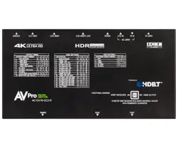
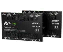
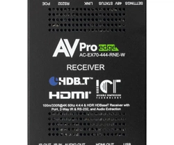
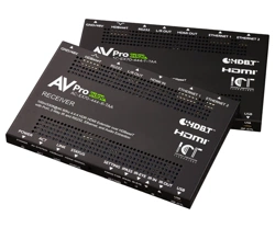
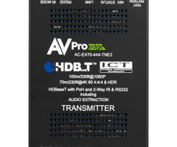
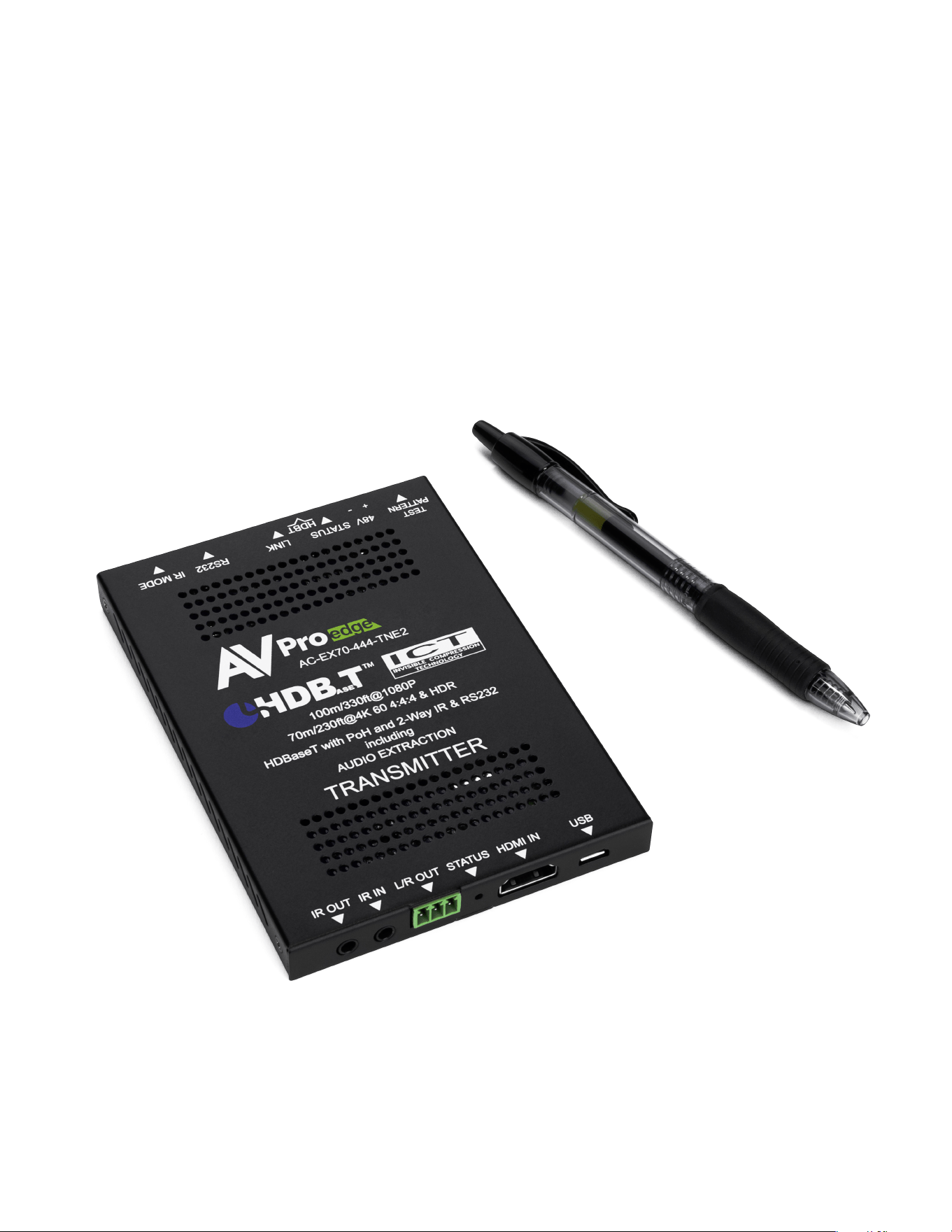
AVPro Edge's 70-meter 4K transmitter can support long-distance runs of high bandwidth data signals
over standard category cable. Professional AV installers will use this device anytime they need to send
HDMI signals long distances. This device will convert the HDMI signal into an HDBaseT type that
distributes uncompressed video data through walls and underground to areas that are not easily
reached.
This device works perfectly with any HDBaseT TV, projector, or AVR, but even more so works with AVPro
Edges scaling HDBaseT Receiver (AC-EX70-SC2-R). When paired together you are in full control of the
video signals that are passing through, you can input a full 4K60 signal, but scale it to a standard 720p
for legacy TVs and projectors.
This transmitter uses ICT Technology to fit the full 4K60 (4:4:4) signal over a single piece of category
cable, we do this by lightly compressing any signal over 10.2Gbps to fit through the category pipeline.
Because this compression is engineered to not affect the picture quality, you have a near-lossless image
on the screen.
Product Overview

Page 3
AC-EX70-444-TNE2
Page 4
AC-EX70-444-TNE2
■
The Transmitter
Back
Front
HDBaseT
IR Mode
RS232
COM & Pass-through)
L/R Out
(PCM Only)
HDMI In
Micro USB
(Firmware)
IR In IR Out
Indicator Troubleshooting Lights on the Transmitter:
POWER - On the front: (Red) This is an indicator that the power is connected. There are only two states for light:
• Light Is On = Power supply is connected and functioning.
• Light Is Off = Power supply is not connected or there is no power present. (In order to have power: check the
power supply, USP, Outlet, etc...)
AV SYSTEM ACT - On the front: (Blue) This is an indicator of activity on the link - this light will blink randomly as data is
sent/received.
HDBaseT LINK - On the front: (Blue) This is an indicator that that the RJ45 HDBaseT Link is stable. This light should
always be SOLID.
HDMI SIGNAL STATUS - On the front: (Blue) This indicator shows that the HDMI source is connected.
The states are:
• Light Is On (Solid) = Sync w/ HDMI source is correct and solid.
• Light Is Flashing = The light flashes during the sync process. If it is flashing continuously, a picture
may not be present.
If the BLUE HDMI SIGNAL STATUS LIGHT is flashing, check the following:
1. The source. Plug it directly into the display to be sure it's functioning properly.
2. Try a longer HDMI cable. Some HDMI cables do not sync well at shorter lengths.
3. Set the EDID to state #1 (See below).
4. If these suggestions do not work, enable the "Test Pattern" (See Below). If you see the pattern, the problem is
between the source and the transmitter, please try a different source.
5. Contact AVProEdge if these suggestions do not work.
48V
Ethernet Ports
10/100
Page 5
AC-EX70-444-TNE2

1. Check the length. The maximum distances are 70m (230ft) on 4K and 100m (330ft) on 1080P.
2. Remove any coils of cable and make sure that there is not excess cabling.
3. Bypass all patch panels and punch-down blocks.
4. Re-terminate connectors. Sometimes, even if a cable tester indicates the run is valid, something may be slightly off.
a. Standard RJ45 ends are recommended. Pass through style types can cause interference/crosstalk
5. Contact AVProEdge if these suggestions do not work.
STATUS- Above RJ45 (HDBT) Port: (Amber) This is an indicator showing that the power is present between the
Transmitter and Receiver. This light ALWAYS BLINKS steadily indicating everything is OK. If you do not see this light,
attempt the following:
1. Check the length. The maximum distances are 70m (230ft) on 4K and 100m (330ft) on 1080P.
2. Remove any coils of cable and make sure that there is not excess cabling.
3. Bypass all patch panels and punch-down blocks.
4. Re-terminate connectors. Sometimes, even if a cable tester indicates the run is valid, something may be just slightly off.
a. Standard RJ45 ends are recommended. Pass through style types can cause interference/crosstalk
5. Try powering from the Receiver instead of the Transmitter (See Receiver page for more about PoE direction).
6. Contact AVProEdge if these steps do not work.
Page 6
AC-EX70-444-TNE2
Indicator Troubleshooting Lights on the Transmitter cont.:
LINK - Above RJ45 (HDBT) Port: (Green) This indicator shows that the AV HDBT link between the Tx and Rx is in tact.
This light should ALWAYS be solid.
If this light is flashing or not present attempt following:
Using the Setting Button:
(On Front) The setting button can be pressed in different combinations based on what
is needed. The status light on the front will flash based on the selection. The selections are in series, meaning, for
example, if you are on selection 5 (listed below), you can come back later and press it again to move you to 6, 7, 8,
1, 2, etc... Using an ink pen is best to press the button.
symbol, and the SETTING INDICATOR LED is just
The SETTING BUTTON is located just to the right
of the to the left of the symbol.
IR Mode Slide Switch: (On Front) This is used to select a preferred IR Mode -
There are two modes:
• IR-EYE - The IR Input will be configured to operate with an IR Receiver Eye.
• I-PASS - The IR Input will be configured to safely operate with a direct connection from a control
system using a mono or stereo 3.5mm cable. It's protected @ 3v-20v. Default mode is IR-EYE.
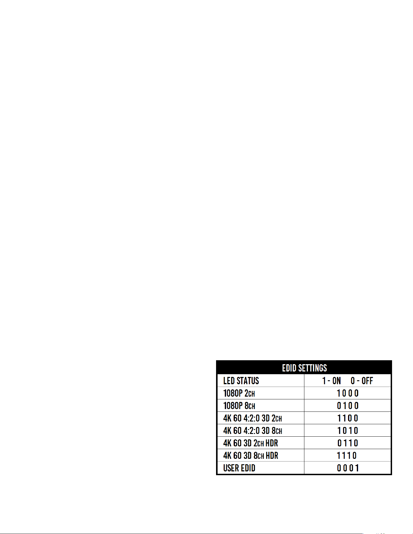
EDID Management: GEN2
(Indicated by part number
AC-EX70-444-T-2)
4 LED lights on the board inside the chassis (see below) Corresponding light will be solid, the others will flash
Page 7
AC-EX70-444-TNE2
Functions & Setup
of the Transmitter:

Functions & Setup of the Transmitter Cont:
Test Pattern Generator:
Press and hold the setting button (for 4 seconds) while powering up the transmitter. You should see the color bar
pattern to the right on screen. When in this mode, you can quick press to toggle the resolution.
Quick press the setting button---Select the test pattern timing.
• 1080P --- LED Flashes 1 Time (3 sets of color bars, example to the right)
• 4K --- LED Flashes 2 Times (5 sets of color bars)
*NOTE: This can be useful for checking your cabling and for
troubleshooting. You can also ensure you have sufficient
distance based on the resolution as well.
While in the USER EDID state (8), press and hold the setting button (for 4 seconds) in order to copy the EDID from the
connected display or downstream device to the user EDID and it will apply automatically.
Why do this?
This is commonly used when there is a need for a specific, known EDID that the installer may prefer. It can also be used if
you want to bypass an EDID of an AVR or another connected device. (IE, plug the extender kit directly into a display and
COPY the EDID. Plug it back into an AVR that may not have a current/good EDID).
Scaler Setting:
While in ANY state besides the USER EDID state, press and hold the setting button (for 4 seconds) to toggle the scaler
mode.
The options are:
COPY DEVICE EDID
Long Range Mode:
150m (500ft) on up to 1080P 8-BIT
1. Enable Test Pattern Mode - Press and hold settings button for 4 seconds while powering up the
transmitter.
2. In Test Pattern Mode - Press and hold the settings button for 4 seconds to enable/disable Long Range
Mode
a. Flash Once - Disabled
b. Flash Twice - Enabled
3. Reboot the extender, Long Range Mode is now active,.
1. Normal Mode(ICT Mode) --- LED Flashes 1 Time
2. Down Scaler Mode (4K->2K) --- LED Flashes 2 Times
Page 8
AC-EX70-444-TNE2

Page 9

• Supplying a hardwire Ethernet connection to video zones for on-device streaming and/or local gaming devices
and players.
• Supplying server based content from a server to a remote display.
• Supplying a zone with a hardwired Ethernet connection for a Wi-Fi access-point in remote zones.
Usage is plug-&-play - the ports are always active and so long as ONE of the FOUR combined ports between the Tx and
Rx is connected to the network the other three have access.
Ethernet Indicator Lights:
• AMBER - This indicates and Ethernet connection is made, and the connection is stable. This should be SOLID.
• GREEN - This indicates that there is activity on the line. This light flashes randomly as data is transmitted. If this light
is steady OFF there is no data coming through or you may need to reset the Ethernet router.
Ethernet Lights & Usage:
Ethernet usage is very straight-forward. It is used for driving network communication over the HDbaseT link. The
purpose of these ports is to act as a "Hub", if you plug one port into a router all the other ports on both the Tx & Rx now
have access to the network.
Usage Examples:
Page 10
AC-EX70-444-TNE2

Functions & Setup
of the Receiver:
Using the Setting Button:
(On Front) The SETTING BUTTON is located just to the left of the POE switch. This
button can be used to enable/disable the built in Test Pattern Generator.
POE Slide Switch: (On Front) This is used to select how you want to PoE is to be directed.
There are two options (you are choosing where the power is ORIGINATING from):
• TX (Default)= You will need to power the TRANSMITTER, the receiver will be powered over
the CAT Cable (Default).
• RX = You will need to power the RECEIVER, the transmitter will be powered over the CAT
Cable from the receiver (This is called "Reverse Power").
Test Pattern Generator:
Press and hold the setting button (for 4 seconds) while powering up the receiver. If you are powering from the
transmitter side, to power cycle the receiver unplug the HDBaseT Category cable. You should see the color bar
pattern appear the right on screen. When in this mode, you can quick press the settings button to toggle the two
resolutions. To Disable, power cycle the receiver.
Quick press the setting button---Select the test pattern timing.
• 1080P --- LED Flashes 1 Time (3 sets of color bars, example below)
• 4K --- LED Flashes 2 Times (5 sets of color bars, example below)
*NOTE: This can be useful for checking your cabling and for troubleshooting. You can also ensure you
have sufficient distance based on the resolution as well.
AC-EX70-444-TNE2
Page 11
1080P Test Pattern 4K Test Pattern

■ RS-232 Configuration
RS-232 can be used to pass control signals bi-directionally to & from any RS-232 compatible device. This is commonly
used to route control signals in the following way:
1. Control System --> Display/Projector (ie, Power On/Off)
2. Display/Projector --> Control System (ie, Display Status, Volume Status etc...)
3. When ultra long-range serial communication is needed (think concerts, live events). Use the extender.
The unit comes with 3 pin connectors to allow
for any wire an integrator would like. The pin
out configuration Left=TX,
Center=Ground, Right=RX and looks like this:
This is how the cable should look. If using the
AC-CABLE-3.5-DB9F (Female) or AC-CABLE-3.5-
DB9M
(Male), the colors will be the same. With any
other cable, please follow Tx, G, Rx as shown
below. See RS-232 cable preparation diagram
below
Page 12
AC-EX70-444-TNE2

■
RS-232 Sample Application
Page 13
AC-EX70-444-TNE2

■
IR Configuration
IR can be used in three ways:
1. From Rack (Control System Direct): Plug a MONO 3.5mm cable into an emitter port of any control system directly
into the "IR IN" port on the AC-EX40-444 Transmitter to pass IR signals directly to the remote end. NOTE - Be sure
the IR MODE Slide Switch is set to "I-PASS" on the Transmitter
2. From Rack (Using IR-EYE): Plug an IR-Receiver Eye into the "IR IN" of the AC-EX40-444 Transmitter in order to pass
infrared signals generated from a device or IR Remote. NOTE - Be sure the IR MODE Slide Switch is set to "IR-EYE"
on the Transmitter.
3. From Remote End: Use an IR-Receiver Eye on the AC-EX40-444 Receiver (IR In Port) in order to send IR signals
BACK to the rack and out of the TRANSMITTER IR Out Port with an emitter.
Page 14
AC-EX70-444-TNE2

■
IR Connections to AC-EX70-444-T (Transmitter)
■
IR Connections to AC-EX70-444-R (Receiver)
IR INPUT
(Receiver Eye)
IR OUTPUT
(IR Emitter)
IR INPUT
(Receiver Eye)
IR OUTPUT
(IR Emitter)
*NOTE: For best results, only use the provided IR EYE's and Emitters
Page 15
AC-EX70-444-TNE2

■
Audio Extraction on AC-EX70-444-TNE
A feature that is always active on the AC-EX70-444 (Tx and Rx) is Audio Extraction. This feature
extracts PCM Audio (2ch) from the source device in order to be run to a separate amplifier or
AVR. BOTH of the audio ports are always active (on Tx & Rx). NOTE - These ports ONLY work if
the source is 2ch. If downmixing is needed, check out AC-AVDM-AUHD or AC-ADM-COTO.
To use the ports:
1. Simply plug a 3 pin terminal block into the port on the Tx or Rx
(both are always active) and make your own cable assembly.
2. There is an option to buy pre-made unbalanced 3-pin to RCA Female cables from
www.avprostore.com
NOTE: The source device needs to output PCM audio in order for the feature to work. This can be
done by using the on-board EDID management or setting the source as such.
■
Audio Extraction Routing Diagram
Page 16
AC-EX70-444-TNE2

■
Stereo Cable Preparation
*NOTE: Pre-made audio cables can be purchased.
The part number is: AC-CABLE-3PIN-2CH.
■ Using Ethernet:
Ethernet usage is very straight-forward. It is used for driving network communication over the HDbaseT link. This of
these ports as a "hub", if you plug one port into a router all the other ports on both the Tx & Rx now have access to
the network.
Usage Examples:
• Supplying a hardwire Ethernet connection to video zones for on-device streaming and/or local gaming devices and
players.
• Supplying server based content from a server to a remote display.
• Supplying a zone with a hardwired Ethernet connection for a Wi-Fi access-point in remote zones.
Usage is plug-&-play - the ports are always active and so long as ONE of the FOUR combined ports between the Tx and Rx
is connected to the network the other three have access.
Ethernet Indicator Lights:
• AMBER - This indicates and Ethernet connection is made, and the connection is stable. This should be SOLID.
• GREEN - This indicates that there is activity on the line. This light flashes randomly as data is transmitted. If this light
is steady OFF there is no data coming through or you may need to reset the Ethernet router.
Page 17
AC-EX70-444-TNE2

■
Troubleshooting
• Verify Power - Pg. 5 & 9
o Verify POE Switch is correct - Pg. 11
• Verify Connections - Check that all cables are properly connected
o TX Indicator Troubleshooting Lights - Pg. 5-6
o RX Indicator Troubleshooting Lights - Pg. 9-10
• Not passing video, this may be an EDID issue. Out of the box the default is EDID BYPASS. Try a canned EDID or
copy the connected displays EDID - Pg. 8
• IR Issues - Verify correct connections - P.14 & 15
o Visibly flashing Emitters may not function properly, try the IR Cables that come in the box
• Extracted Audio Issues - Pg.16-17
o Verify Source is set to output 2ch PCM
Note: This unit does NOT downmix
• Still having issues, contact us
o Support Direct - +1-605-977-3477
+1-605-274-6055
o Submit a support request ticket
https://support.avproedge.com/hc/en-us/requests/new
Page 18
AC-EX70-444-TNE2

• U
s
e t
he
p
owe
r supplies provided. If an alternate supply
is r
eq
uired, check voltage, polarity and
that
it has
suff
icient power to supply the device it is connected
to.
• Do not
operate t
hese
p
r
oducts outside the
s
pec
ified temperature and humidity range given in the ab
ove
sp
eci
fi
c
ations.
• En
s
u
r
e there is adequate ventilation to
allow t
his product to operate efficiently.
• Repair of the equipment should only be carried out by qualified professionals as these products contain
sensitive components that may be
damaged by any mistreatment.
• Only use this
product in a dry
environment. Do not all
ow any liquids
or harmful chemicals to come i
nto contact
w
it
h these products.
• Clean t
his unit w
it
h
a
s
of
t
, dry clot
h. N
ever use alcohol, paint
thinner or benzene to clean this unit.
Maintenance
To ensure reliable operation of this product as well as protecting the safety of any person using or handling
this device while powered, please observe the following instructions.
• Th
e D
C power supply cord or
AC adaptor has been d
amage
d
• Ob
je
c
ts or
liquids have g
otten into the unit
• Th
e u
ni
t has
be
en
e
x
po
s
ed to
r
ai
n
• The unit does not operate normally or exhibits a marked change in performance
• The unit has been dropped or the housing damaged
Damage Requiring Service
The unit should be serviced by qualified service personnel if:
Page 19
AC-EX70-444-TNE2

Support
Should you experience any problems while using this product, first, refer to the Troubleshooting section of this manual
before contacting Technical Support. When calling, the following information should be provided:
• Product name and model number
• Product serial number
• Details of the issue and any conditions under which the issue is occurring
Warranty
If your product does not work properly because of a defect in materials or
workmanship, AVProEdge (referred to as “the warrantor”) will, for the length of the period indicated as below, (Parts/
Labor (10) Years), which starts with the date of original purchase (“Limited Warranty period”), at its option either (a)
repair your product with new or refurbished parts, or (b) replace it with a new or a refurbished product. The decision to
repair or replace will be made by the warrantor. During the “Labor” Limited Warranty period there will be no charge
for labor. During the “Parts” warranty period, there will be no charge for parts. You must mail-in your product during
the warranty period. This Limited Warranty is extended only to the original purchaser and only covers product
purchased as new. A purchase receipt or other proof of original purchase date is required for Limited Warranty service.
This warranty extends to products purchased directly from AVPro or an authorized dealer. AVPro is not liable to honor
this warranty if the product has been used in any application other than that for which it was intended, has been
subjected to misuse, accidental damage, modification or improper installation procedures, unauthorized repairs or is
outside of the warranty period. Please direct any questions or issues you may have to your local dealer before
contacting AVPro.
Page 20
AC-EX70-444-TNE2

_____________________________________________
_____________________________________________
_____________________________________________
_____________________________________________
_____________________________________________
_____________________________________________
_____________________________________________
_____________________________________________
_____________________________________________
_____________________________________________
_____________________________________________
_____________________________________________
_____________________________________________
_____________________________________________
_____________________________________________
_____________________________________________
_____________________________________________
_____________________________________________
_____________________________________________
_____________________________________________
_____________________________________________
_____________________________________________
_____________________________________________
_____________________________________________
_____________________________________________
_____________________________________________
_____________________________________________
Page 21
AC-EX70-444-TNE2

_____________________________________________
_____________________________________________
_____________________________________________
_____________________________________________
_____________________________________________
_____________________________________________
_____________________________________________
_____________________________________________
_____________________________________________
_____________________________________________
_____________________________________________
_____________________________________________
_____________________________________________
_____________________________________________
_____________________________________________
_____________________________________________
_____________________________________________
_____________________________________________
_____________________________________________
_____________________________________________
_____________________________________________
_____________________________________________
_____________________________________________
_____________________________________________
_____________________________________________
_____________________________________________
_____________________________________________
Page 22
AC-EX70-444-TNE2
AVProEdge
2222 E 52nd St N ~ Sioux Falls, SD 57104
1-877-886-5112 ~ 605-274-6055
Thank you for choosing AVProEdge!
Please contact us with any questions, we are happily at
your service!
Page 23
AC-EX70-444-TNE2