FIT FOR ALL MODELS
OF PICKUPS, TRUCKS
TRAILERS, SUVS, VANS
UNIVERSAL
WIRELESS AIR SPRING LEVELING ELECTRIC
CONTROLLER KIT
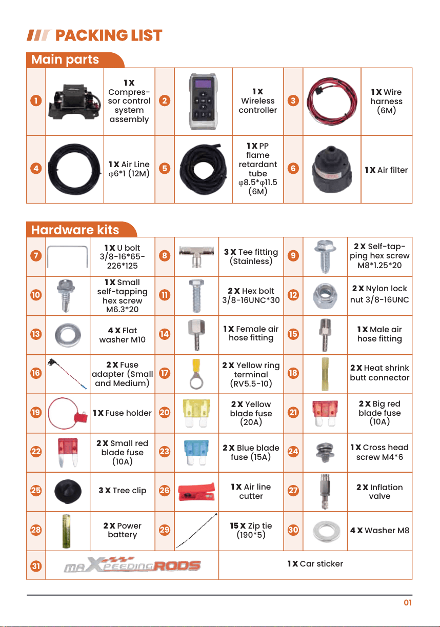
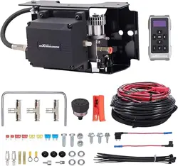
1 X
Compres-
sor control
system
assembly
1
1 X
Wireless
controller
2
1 X Wire
harness
(6M)
3
1 X Air Line
φ6*1 (12M)
4
1 X PP
flame
retardant
tube
φ8.5*φ11.5
(6M)
5
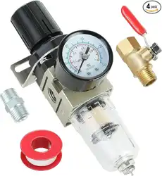
1 X Air filter
6
1 X U bolt
3/8-16*65-
226*125
3 X Tee fitting
(Stainless)
2 X Self-tap-
ping hex screw
M8*1.25*20
1 X Small
self-tapping
hex screw
M6.3*20
2 X Hex bolt
3/8-16UNC*30
2 X Nylon lock
nut 3/8-16UNC
4 X Flat
washer M10
1 X Female air
hose fitting
1 X Male air
hose fitting
2 X Fuse
adapter (Small
and Medium)
2 X Yellow ring
terminal
(RV5.5-10)
2 X Heat shrink
butt connector
1 X Fuse holder
2 X Yellow
blade fuse
(20A)
2 X Big red
blade fuse
(10A)
2 X Small red
blade fuse
(10A)
2 X Blue blade
fuse (15A)
1 X Cross head
screw M4*6
3 X Tree clip
1 X Air line
cutter
2 X Inflation
valve
2 X Power
battery
15 X Zip tie
(190*5)
4 X Washer M8
1 X Car sticker
7 8 9
10 11 12
13 14 15
16 17 18
19 20 21
22 23 24
25 26 27
28
31
29 30
01
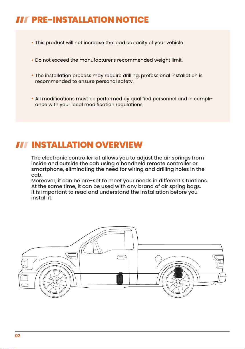
The electronic controller kit allows you to adjust the air springs from
inside and outside the cab using a handheld remote controller or
smartphone, eliminating the need for wiring and drilling holes in the
cab.
Moreover, it can be pre-set to meet your needs in different situations.
At the same time, it can be used with any brand of air spring bags.
It is important to read and understand the installation before you
install it.
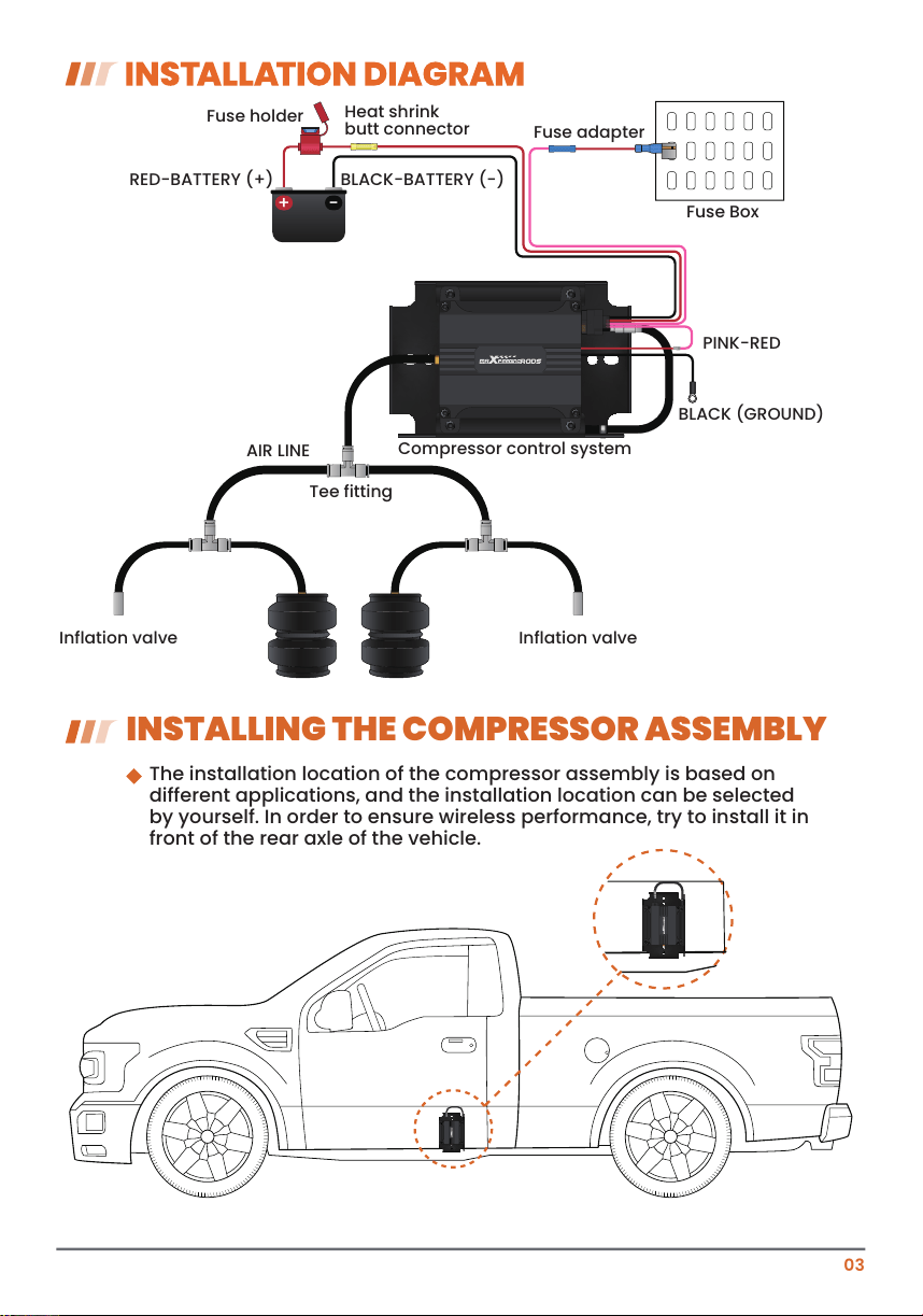
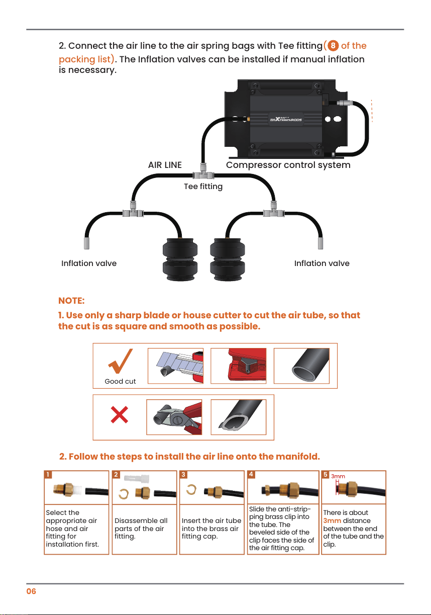
Fuse Box
AIR LINE
Compressor control system
Tee fitting
Inflation valveInflation valve
+ -
BLACK (GROUND)
PINK-RED
RED-BATTERY (+)
Fuse holder
Heat shrink
butt connector
Fuse adapter
BLACK-BATTERY (-)
INSTALLING THE COMPRESSOR ASSEMBLY
The installation location of the compressor assembly is based on
different applications, and the installation location can be selected
by yourself. In order to ensure wireless performance, try to install it in
front of the rear axle of the vehicle.
03
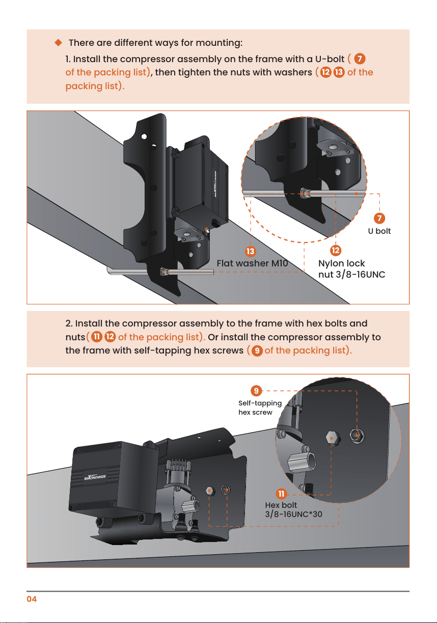
There are different ways for mounting:
1. Install the compressor assembly on the frame with a U-bolt
(
of the packing list), then tighten the nuts with washers ( of the
packing list).
12 13
7
2. Install the compressor assembly to the frame with hex bolts and
nuts( of the packing list). Or install the compressor assembly to
the frame with self-tapping hex screws ( of the packing list).
9
11 12
Nylon lock
nut 3/8-16UNC
U bolt
Flat washer M10
12
13
7
Hex bolt
3/8-16UNC*30
Self-tapping
hex screw
11
9
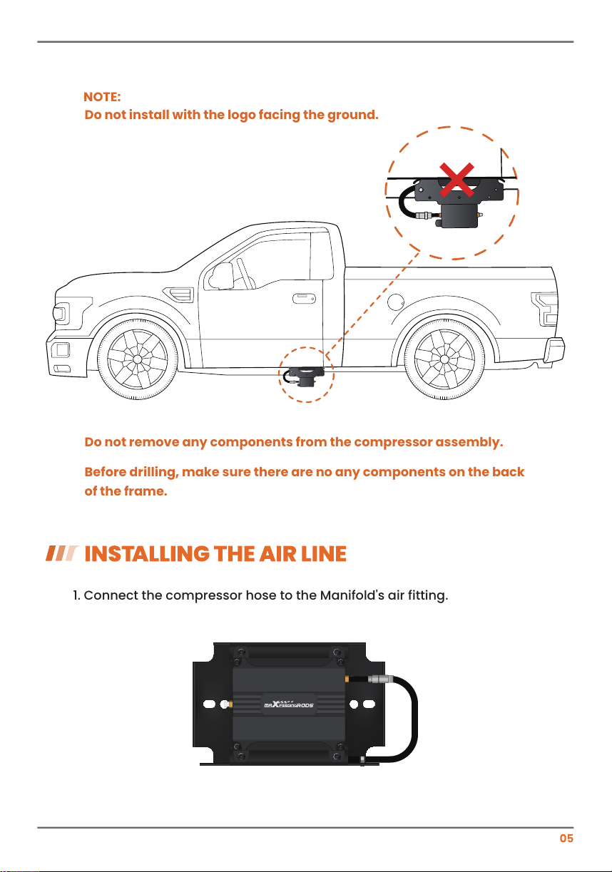
1. Connect the compressor hose to the Manifold's air fitting.
NOTE:
Do not remove any components from the compressor assembly.
Before drilling, make sure there are no any components on the back
of the frame.
Do not install with the logo facing the ground.
×
2. Follow the steps to install the air line onto the manifold.
Select the
appropriate air
hose and air
fitting for
installation first.
1
Slide the anti-strip-
ping brass clip into
the tube. The
beveled side of the
clip faces the side of
the air fitting cap.
4
There is about
3mm distance
between the end
of the tube and the
clip.
3mm
5
Disassemble all
parts of the air
fitting.
2
Insert the air tube
into the brass air
fitting cap.
3
NOTE:
1. Use only a sharp blade or house cutter to cut the air tube, so that
the cut is as square and smooth as possible.
Good cut
√
×
Compressor control systemAIR LINE
Tee fitting
Inflation valveInflation valve
2. Connect the air line to the air spring bags with Tee fitting( of the
packing list). The Inflation valves can be installed if manual inflation
is necessary.
8
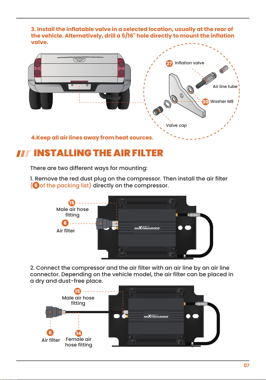
3. Install the inflatable valve in a selected location, usually at the rear of
the vehicle. Alternatively, drill a 5/16" hole directly to mount the inflation
valve.
4.Keep all air lines away from heat sources.
Inflation valve
Washer M8
Air line tube
Valve cap
27
30
There are two different ways for mounting:
1. Remove the red dust plug on the compressor. Then install the air filter
(N of the packing list)
directly on the compressor.
2. Connect the compressor and the air filter with an air line by an air line
connector. Depending on the vehicle model, the air filter can be placed in
a dry and dust-free place.
INSTALLING THE AIR FILTER
Air filter
Male air hose
fitting
Female air
hose fitting
6
6
14
15
Air filter
6
Male air hose
fitting
15
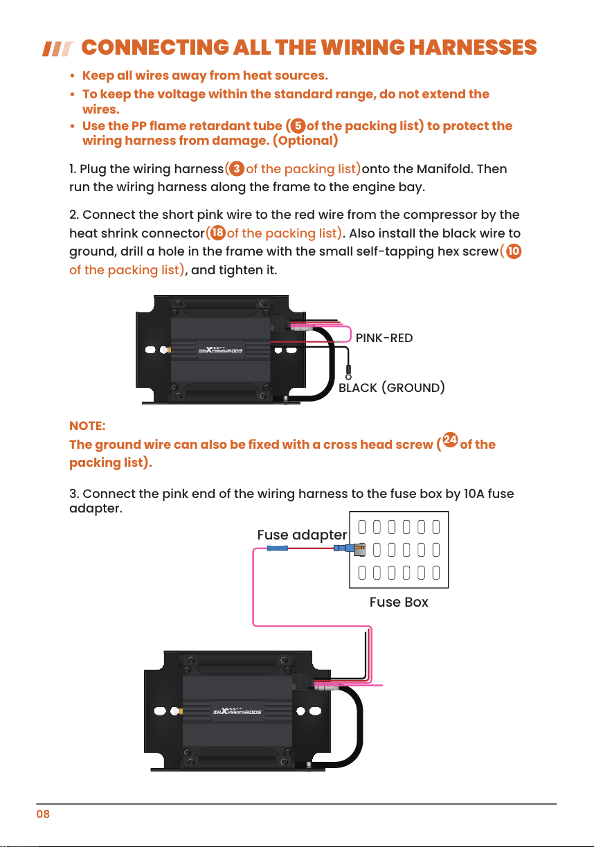
CONNECTING ALL THE WIRING HARNESSES
• To keep the voltage within the standard range, do not extend the
wires.
• Keep all wires away from heat sources.
NOTE:
The ground wire can also be fixed with a cross head screw ( of the
packing list).
1. Plug the wiring harness( of the packing list)onto the Manifold. Then
run the wiring harness along the frame to the engine bay.
3. Connect the pink end of the wiring harness to the fuse box by 10A fuse
adapter.
BLACK (GROUND)
PINK-RED
Fuse Box
Fuse adapter
3
24
2. Connect the short pink wire to the red wire from the compressor by the
heat shrink connector( of the packing list). Also install the black wire to
ground, drill a hole in the frame with the small self-tapping hex screw(
of the packing list), and tighten it.
18
10
08
• Use the PP flame retardant tube ( of the packing list) to protect the
wiring harness from damage. (Optional)
5
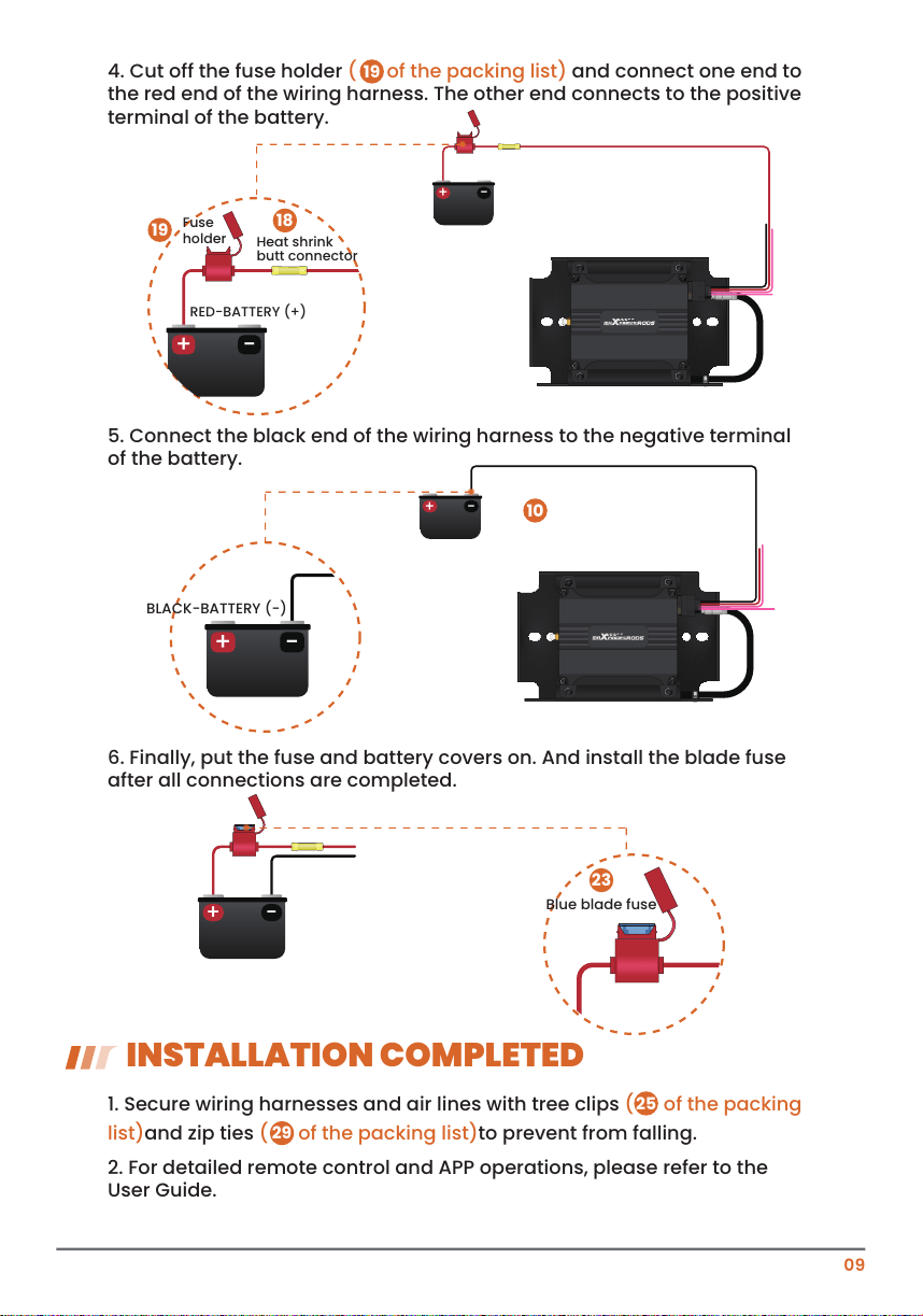
4. Cut off the fuse holder ( of the packing list) and connect one end to
the red end of the wiring harness. The other end connects to the positive
terminal of the battery.
5. Connect the black end of the wiring harness to the negative terminal
of the battery.
6. Finally, put the fuse and battery covers on. And install the blade fuse
after all connections are completed.
1. Secure wiring harnesses and air lines with tree clips
( of the packing
list)and zip ties ( of the packing list)to prevent from falling.
2. For detailed remote control and APP operations, please refer to the
User Guide.
INSTALLATION COMPLETED
19
+ -
Blue blade fuse
23
+ -
+ -
BLACK-BATTERY (-)
+ -
RED-BATTERY (+)
Fuse
holder
Heat shrink
butt connector
+ -
18
19
10
25
29
09

ABK-AAPGAOPEI-VLC-A