
Technical Support and E-Warranty Certificate www.vevor.com/support
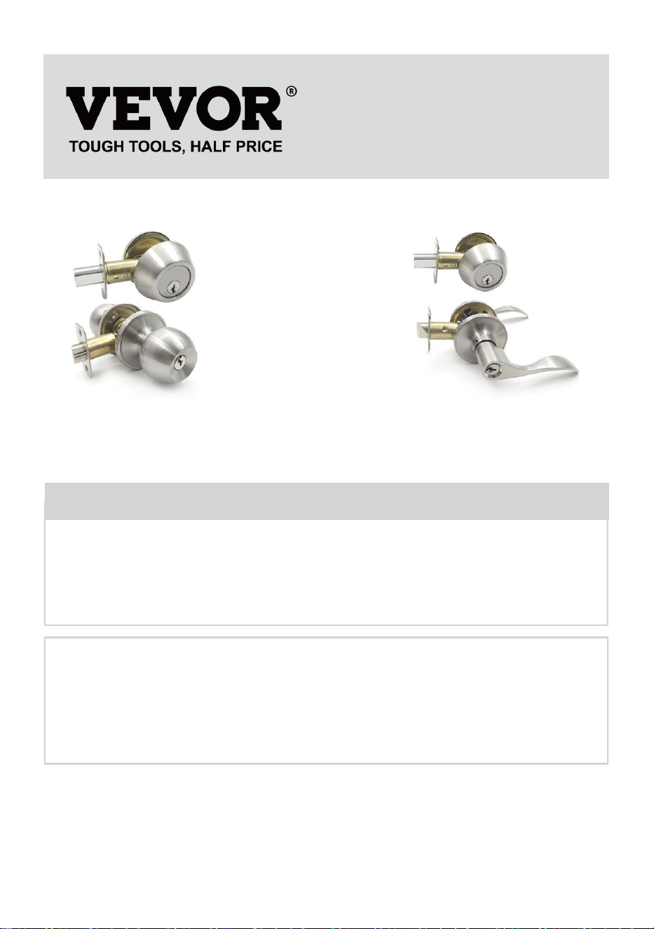
Door Locksets
Instruction Manual
MODEL: 587+D1 01 、 368 3 +D 1 0 1
We continue to be committed to provide you tools with competitive price.
"Save Half", "Half Price" or any other similar expressions used by us only represents an
estimate of savings you might benefit from buying certain tools with us compared to the major
top brands and does not necessarily mean to cover all categories of tools offered by us. You
are kindly reminded to verify carefully when you are placing an order with us if you are
actually saving half in comparison with the top major brands.

MODEL: 587+D101 MODEL: 3683+D101
★ The picture is for reference only, please refer to the actual.
Have product questions? Need technical support? Please feel free to
contact us:
Technical Support and E-Warranty Certificate
www.vevor.com/support
NEED HELP? CONTACT US!
This is the original instruction, please read all manual instructions
carefully before operating. VEVOR reserves a clear interpretation of our
user manual. The appearance of the product shall be subject to the
product you received. Please forgive us that we won't inform you again if
there are any technology or software updates on our product.
Door Locksets
Warning-To reduce the risk of injury, user must read
instructions manual carefully.
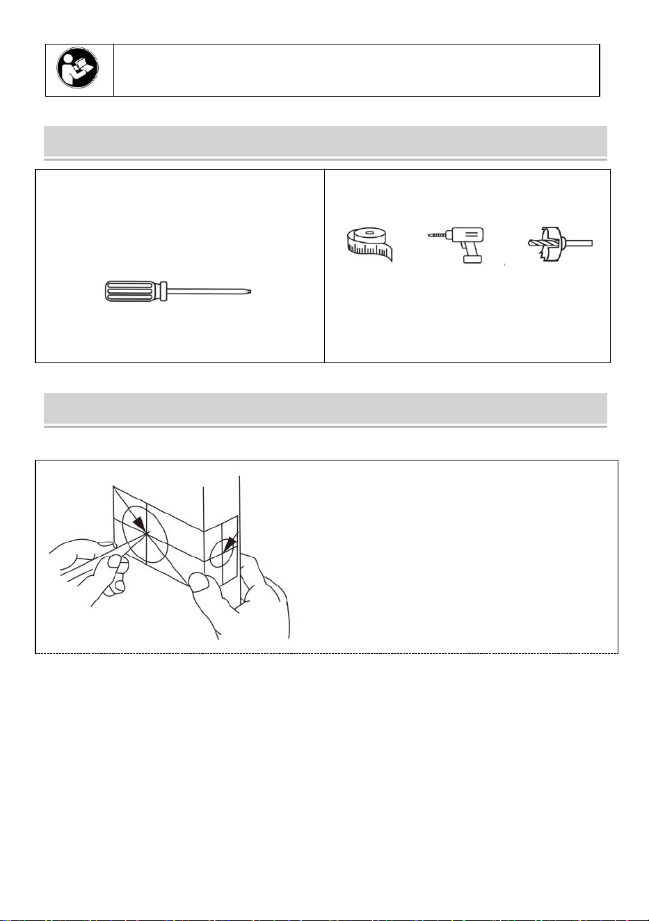
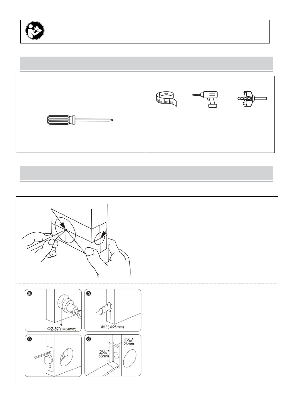
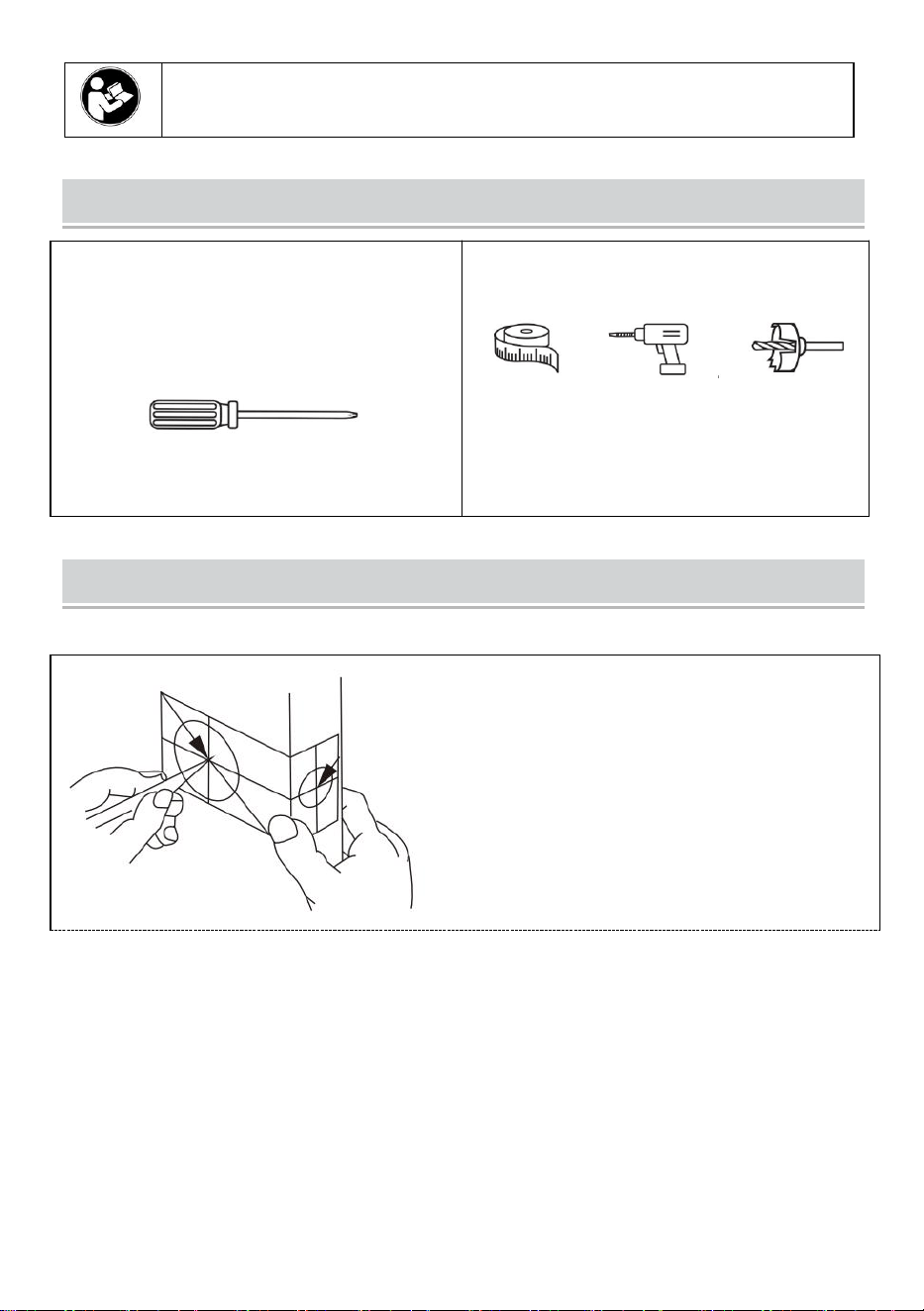
Installation tools
Tools Required for Replacement Installation
Phillips Screwdriver
Extra Tools Required for New Installation
Measuring Tape 1" Hole Boring Bit
Additional tools(if needed): chisel, hammer, pencil,
safety glasses.
Installation Instructions
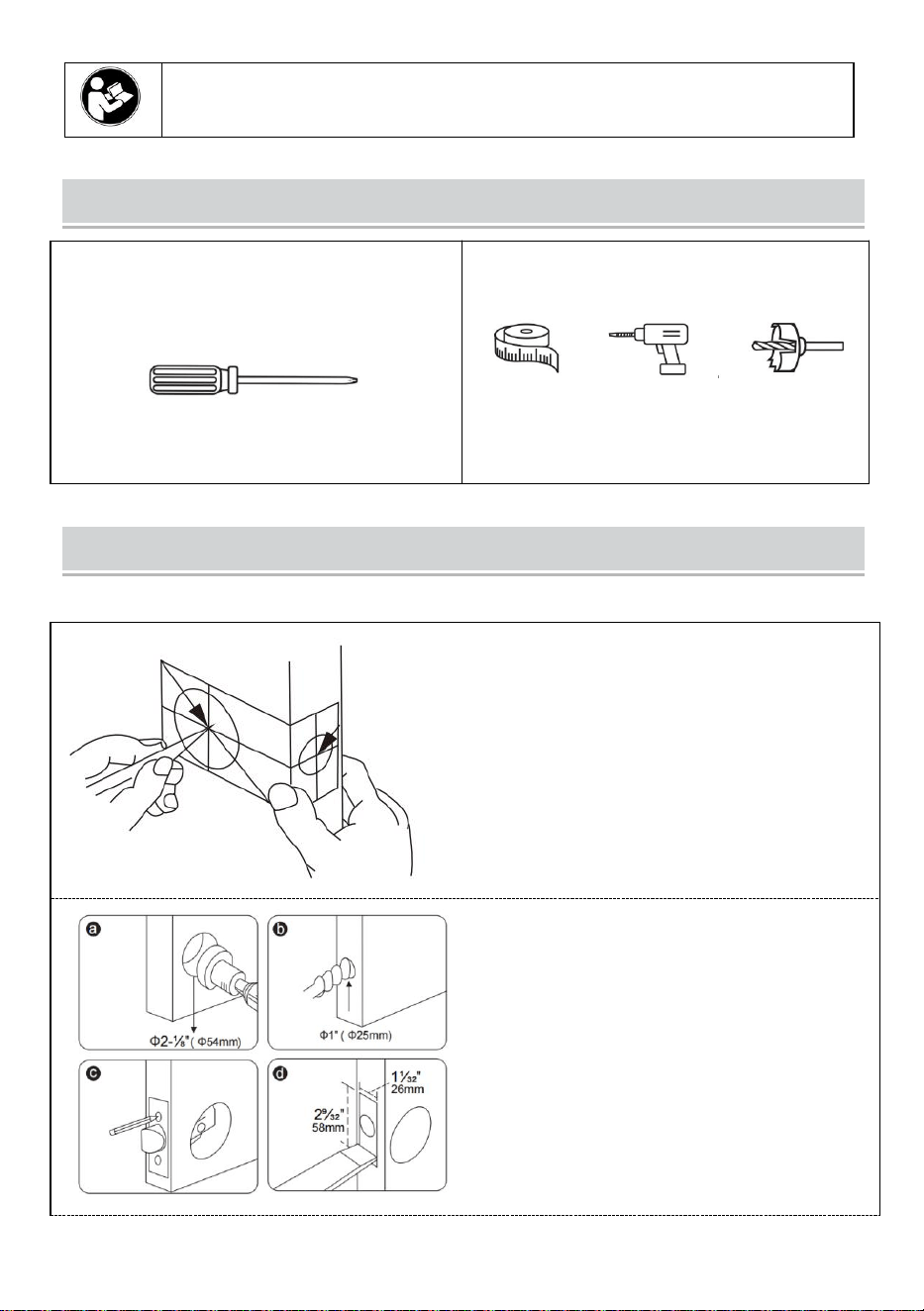
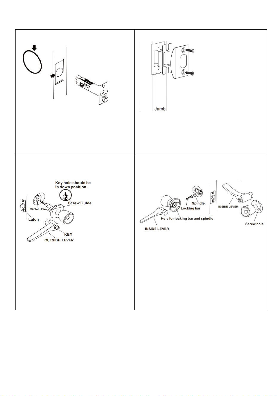
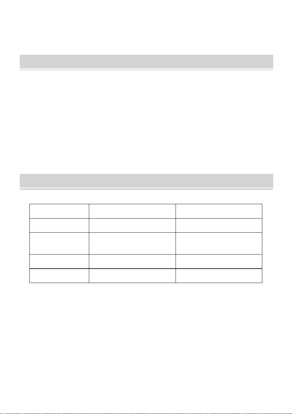
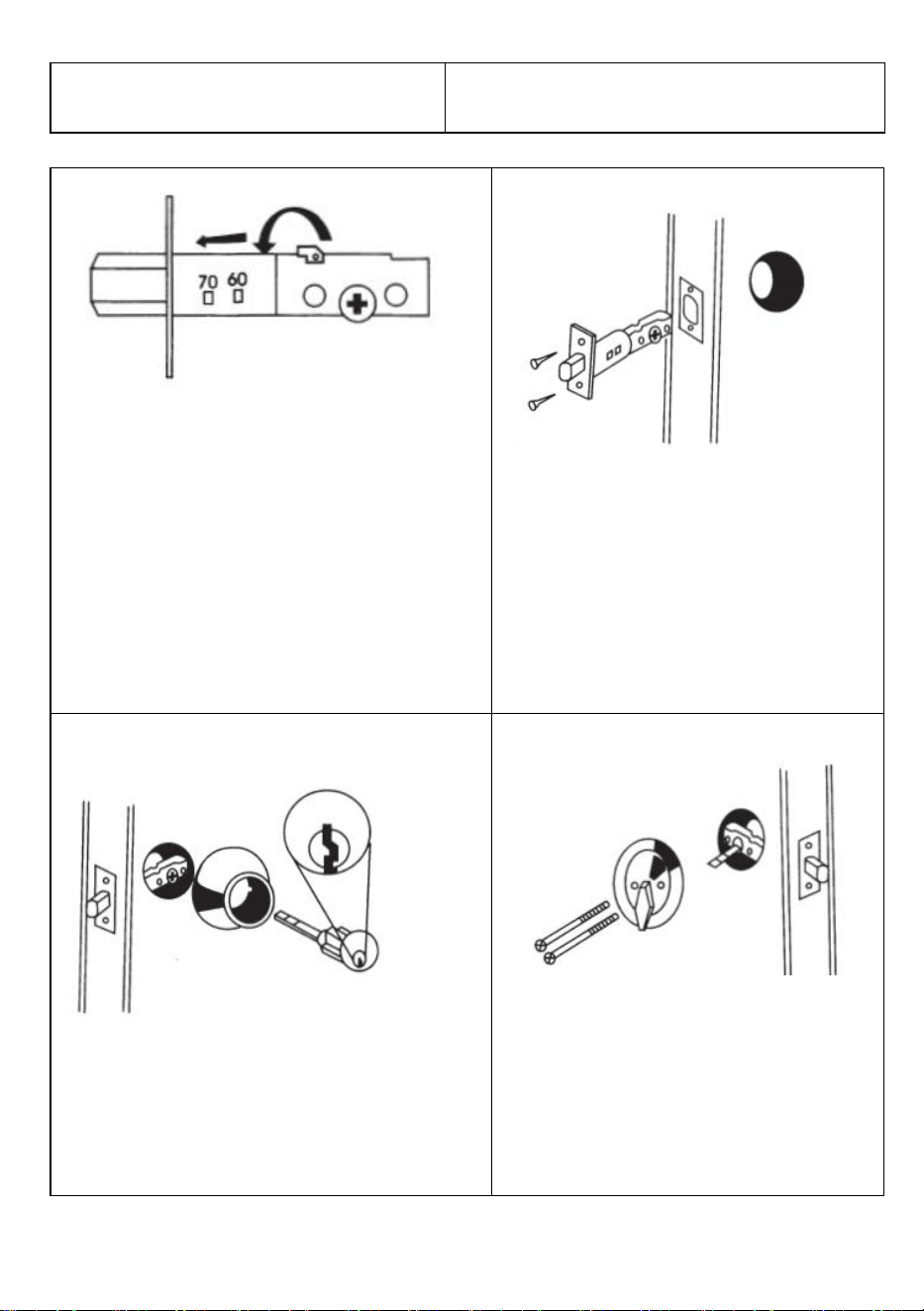
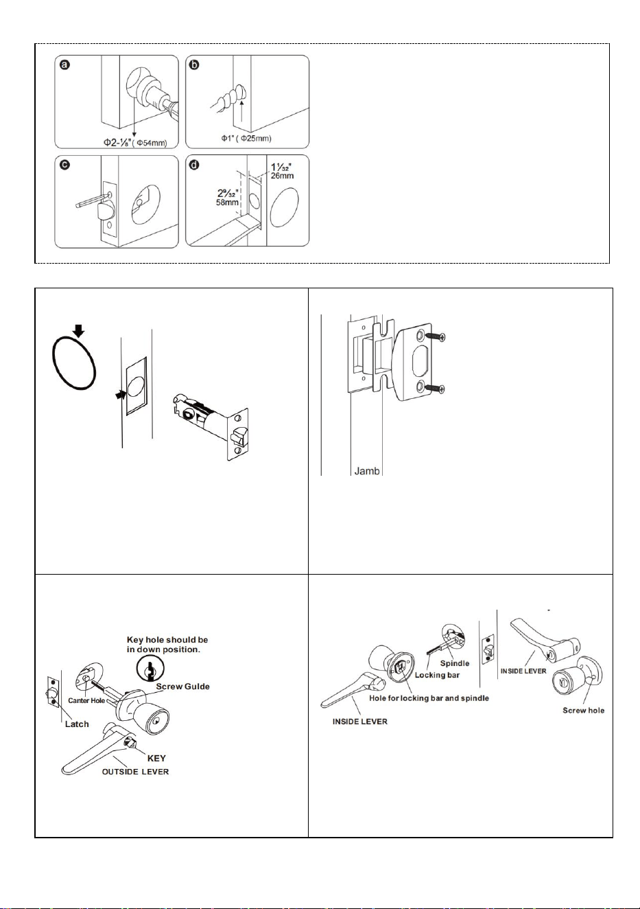
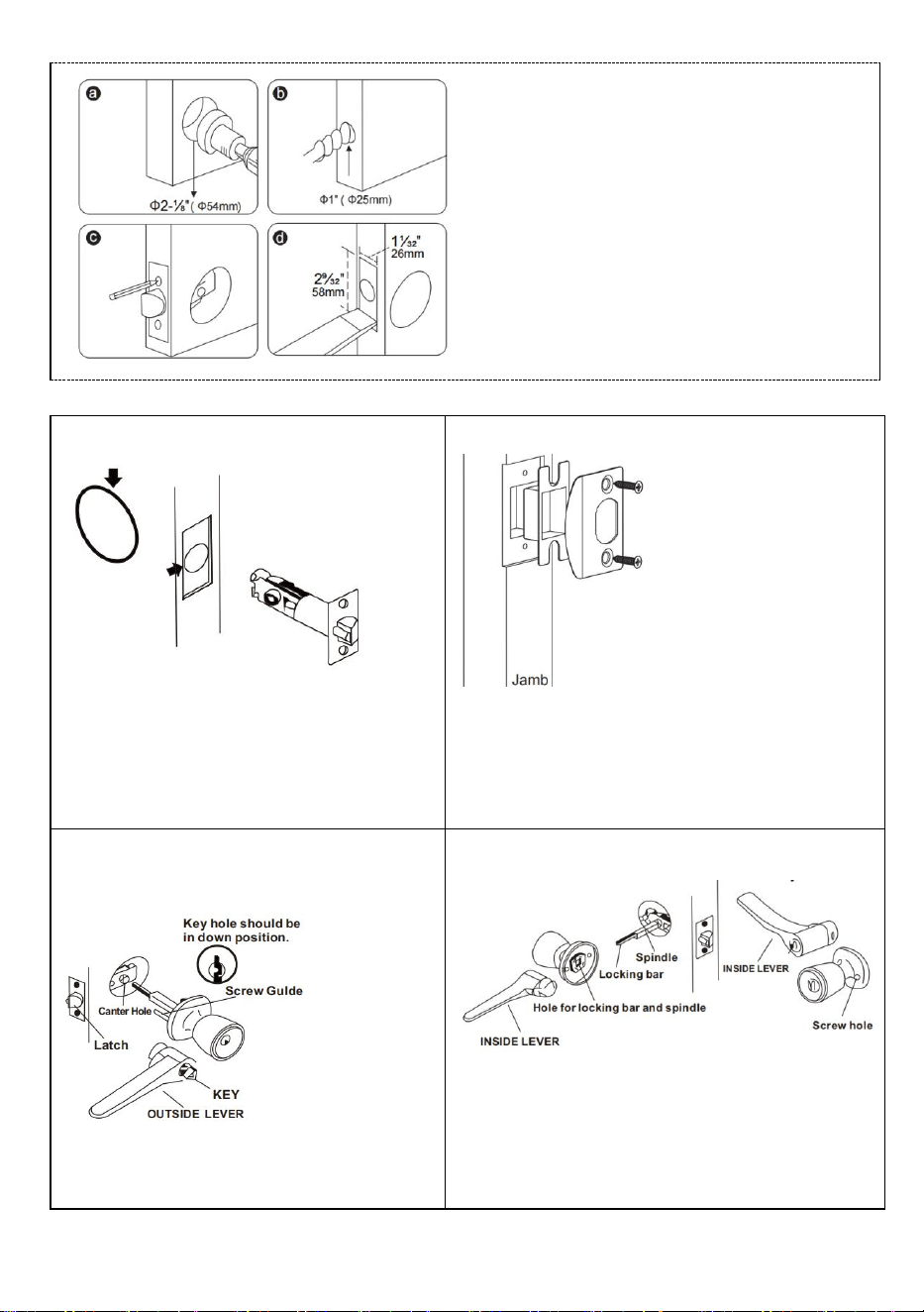
(1)Drill Holes
a. Fold the template at the dotted line
and tape the template to the interior
side of the door at 34 to 48 inch Height.
b. Measure the thickness of the door
and mark the middle point of the door
thickness.
c. Mark the (60 or 70mm) hole center for
the backset.
Note: Make sure the two dots are at the
same height.
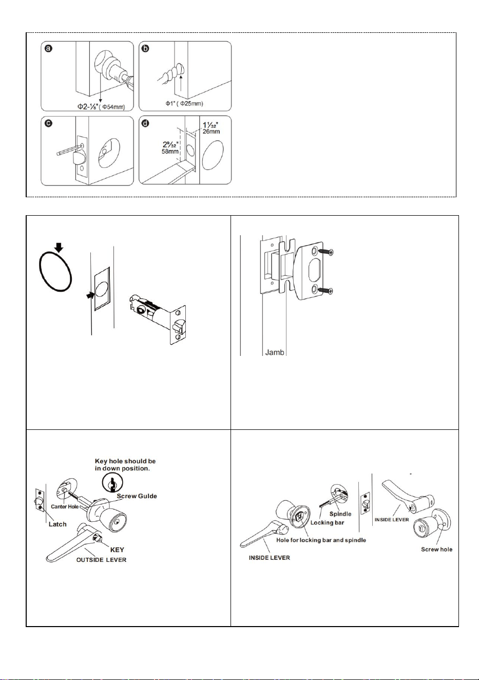
2⅛" Hole
Boring Saw
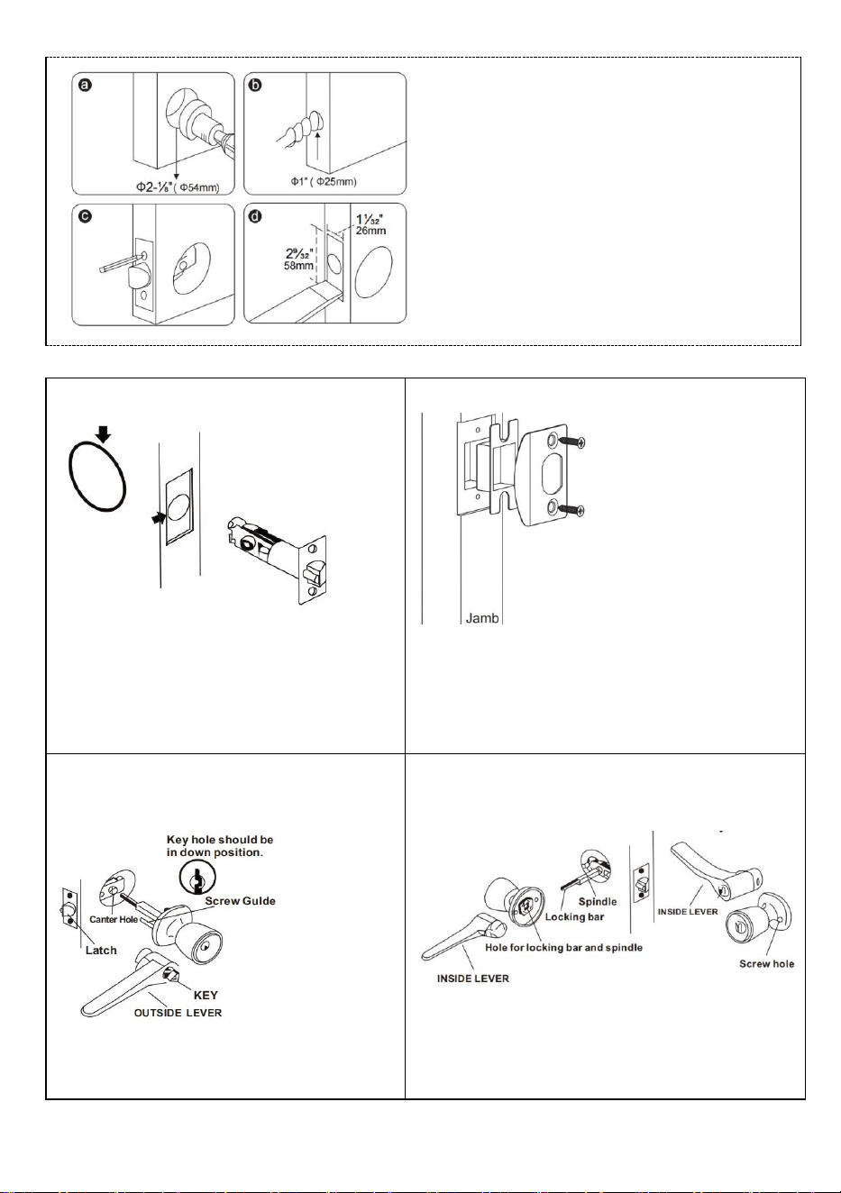
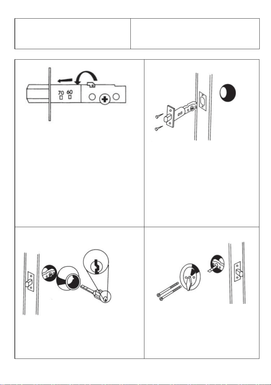
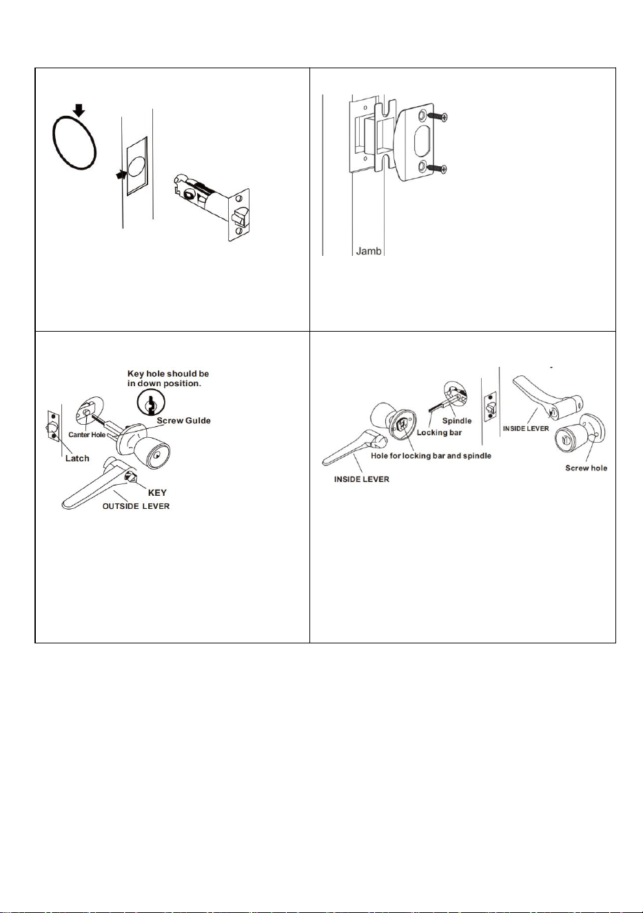
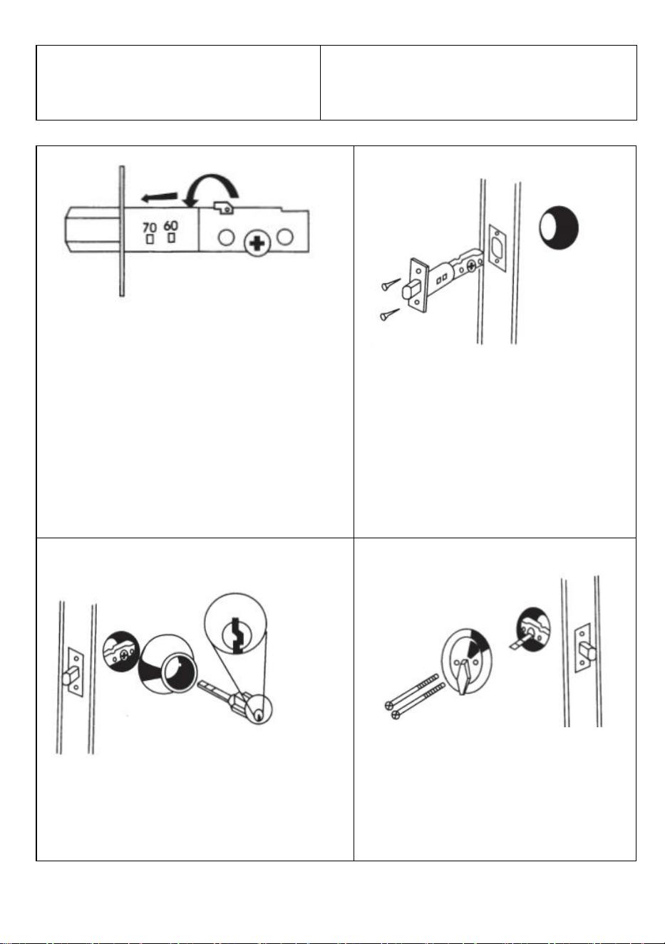
(2)Installation Instructions Of Ball Lockset Or Wave Shaped Lockset
1.Install the latch
1.Install deadbolt latch
in"up"position into door hole.
2.Insert and secure with screws.
2.Install Striking Plate
Striking Plate against strike as
illustrated, preventing forcing when
door is closed.
3.Install Outside Knob Unit
Install outside knob unit with screw
guides, locking bar and spindle
engaged into latch as illustrated.
4. Install Inside Knob Unit.
1.Engage screw guides, locking bar and
spindle into inside unit..
2.Insert screws and tighten securely.
a. Drill a Dia. (54mm) hole for the lock
body.
b. Drill a Dia. (25mm) hole for the latch.
c. Insert the latch into the hole and mark
the outline of the faceplate.
d. Chisel a (3mm) deep hole for the
faceplate.
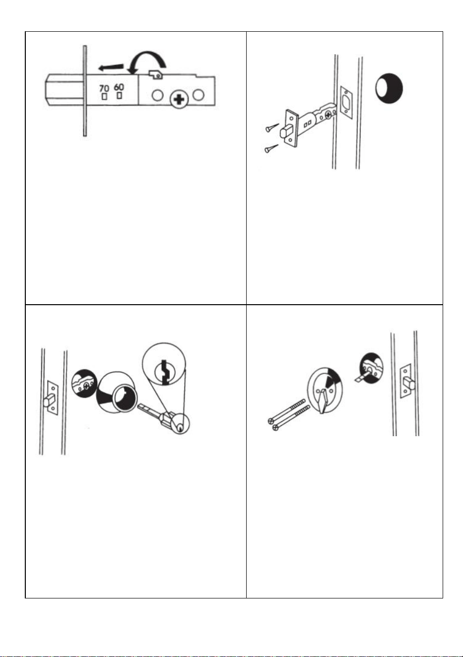
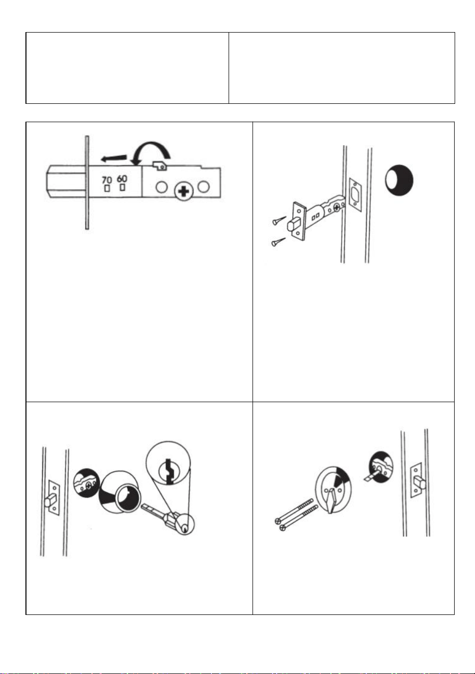
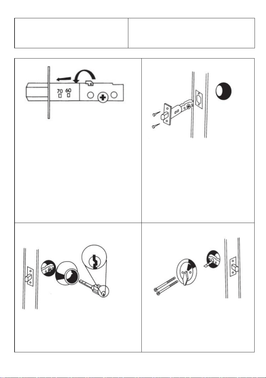
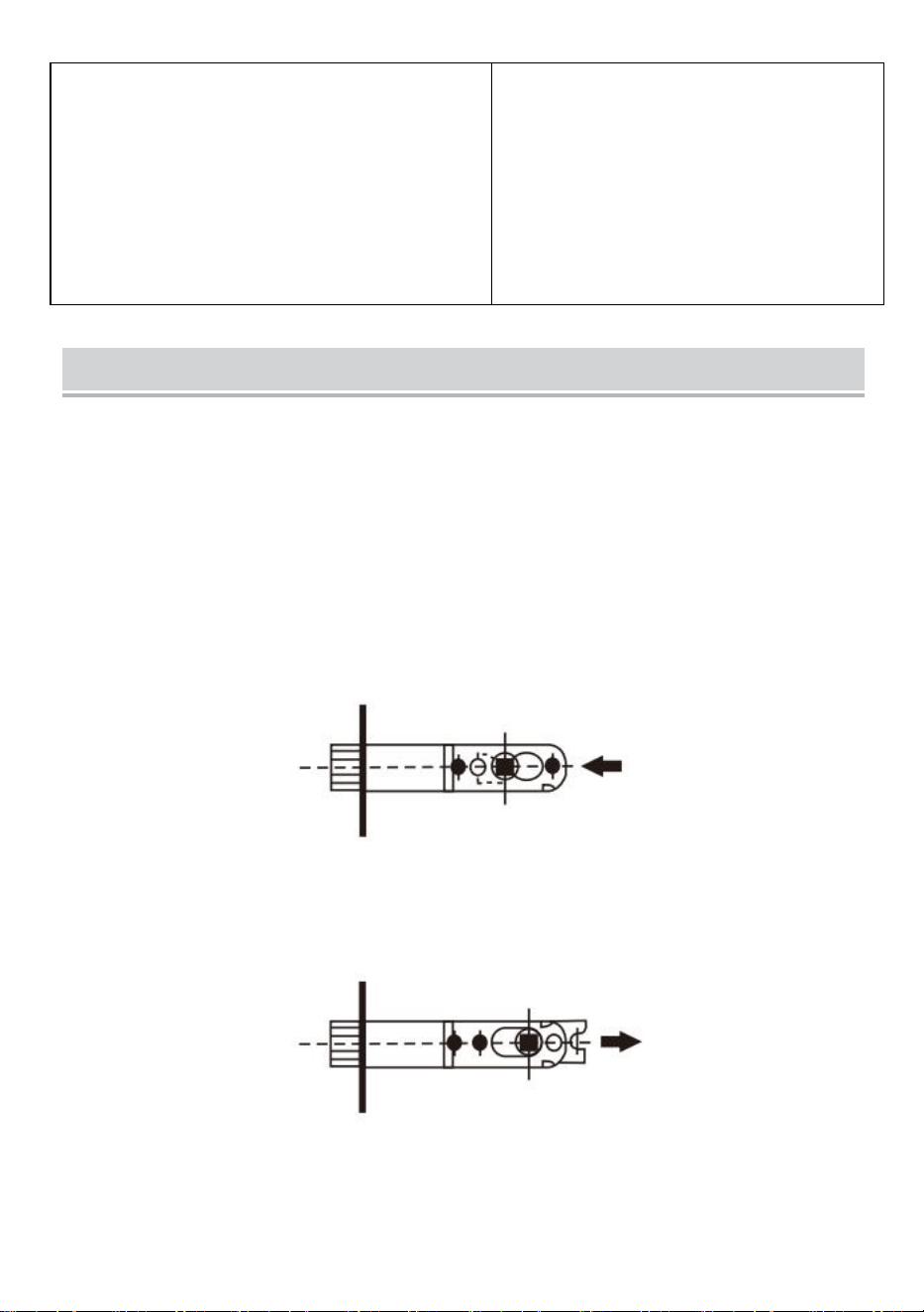
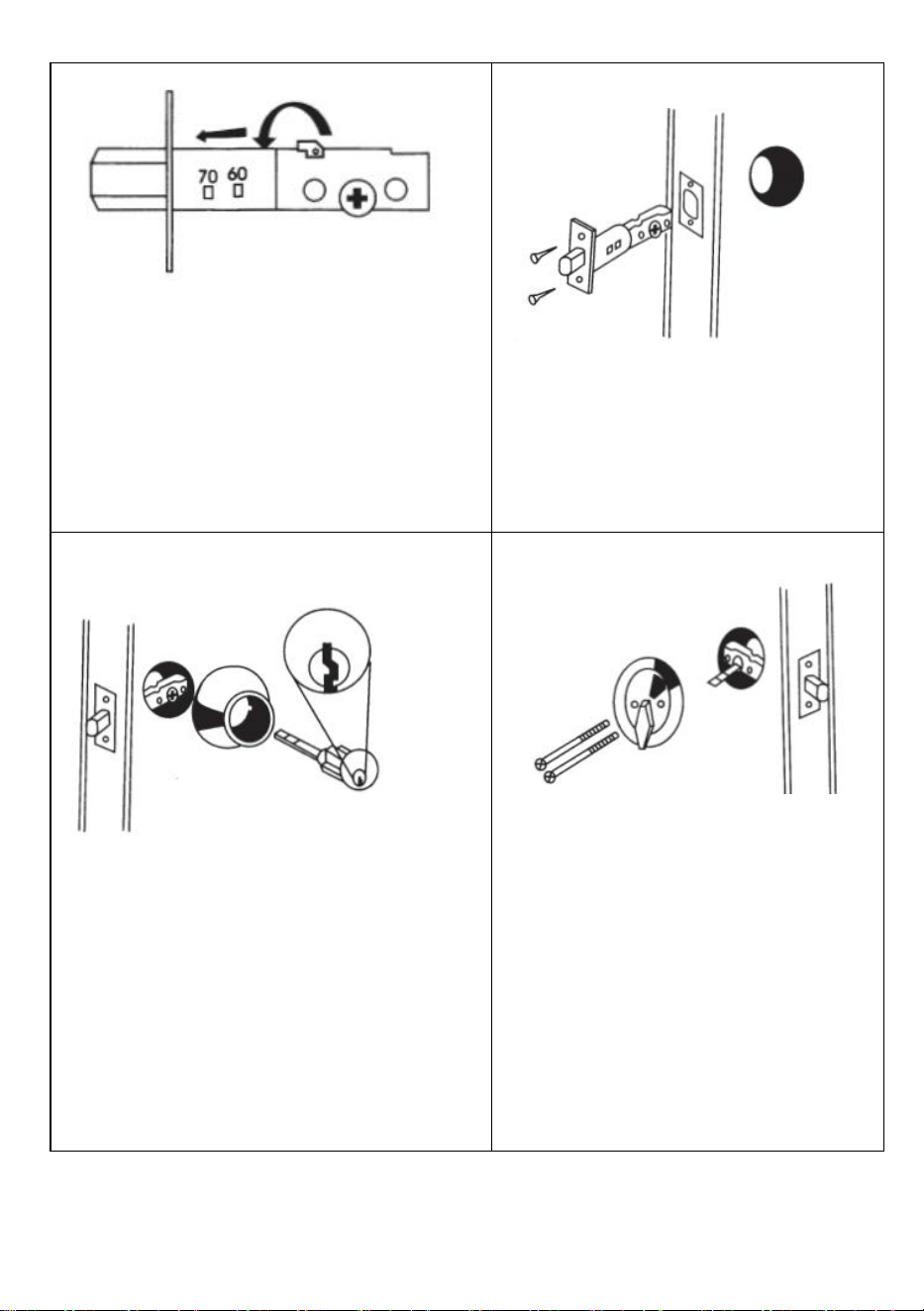
(3)Installation Instructions Of Deadbolt Lockset
Your Latch is factory set for
2-3/8"(60mm) If your door requires
a2-3/4" (70mm) Latch, follow these
steps.
A.Hold Latch in your right hand so you
can see adjustment holes.With left hand
turn latch plate in clockwise
position.pull latch plate out of sase as
far as it will go.
B.Turn back and lock into 70mm
position
1. Install the latch
1.Install deadbolt latch
in"up"position into door hole.
2.Insert and secure with screws.
2. Install Exterior Assembly
1.Place cylinder assembly through
outside cylinder guard and on door
making sure torque blade is properiy
positioned in latch crank.
2.Put key in cylinder and turn until
Deadbolt is exposed. Note:Keyhole
must be in the "down"position as
shown.
3. Install Interior Assembly
Make sure Deadbolt is in Locked
position.
Place thumb turn assembly onto
torque blade and line up screw
holes.The thumb knob will be in
the "up" position so you can see
the screwholes.Tighten long
machine screws
Note
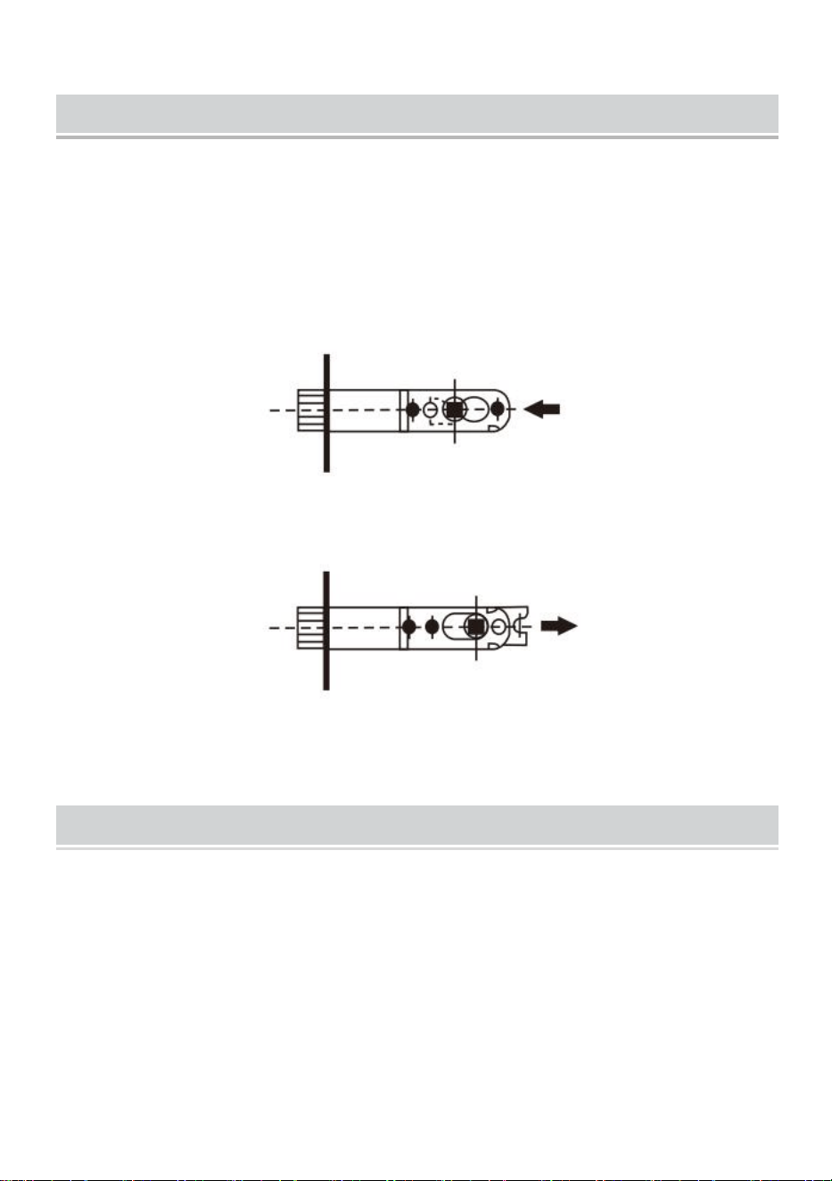
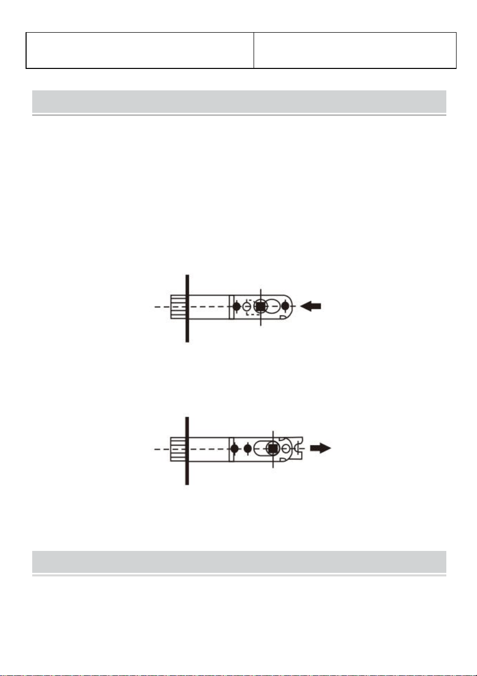
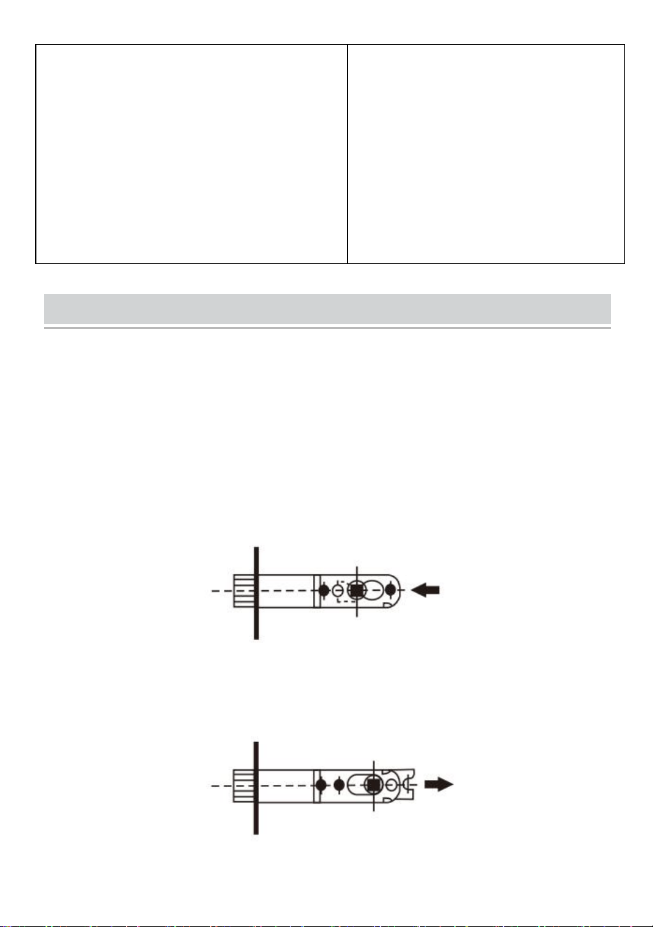
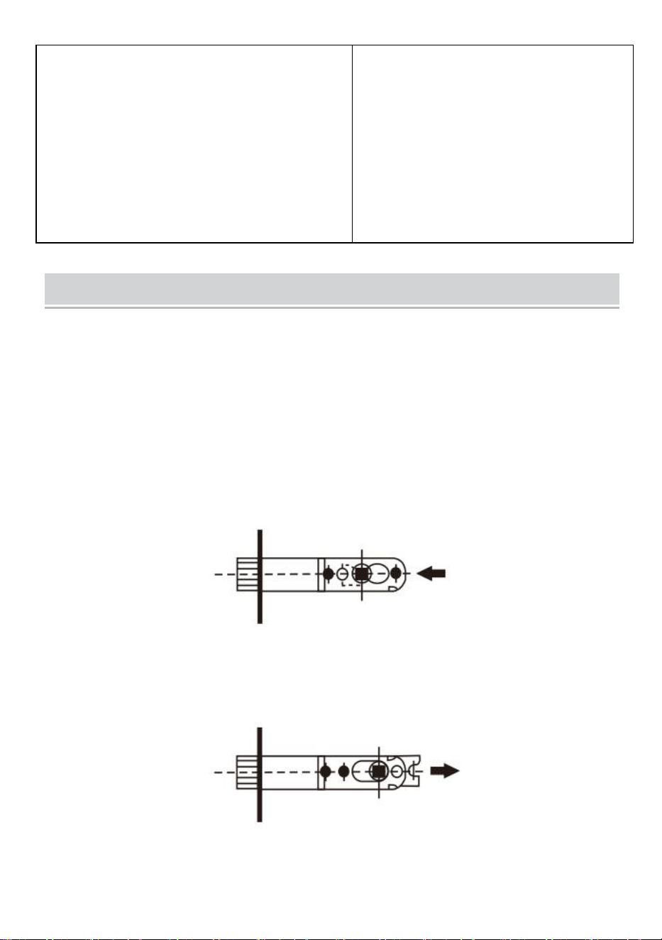
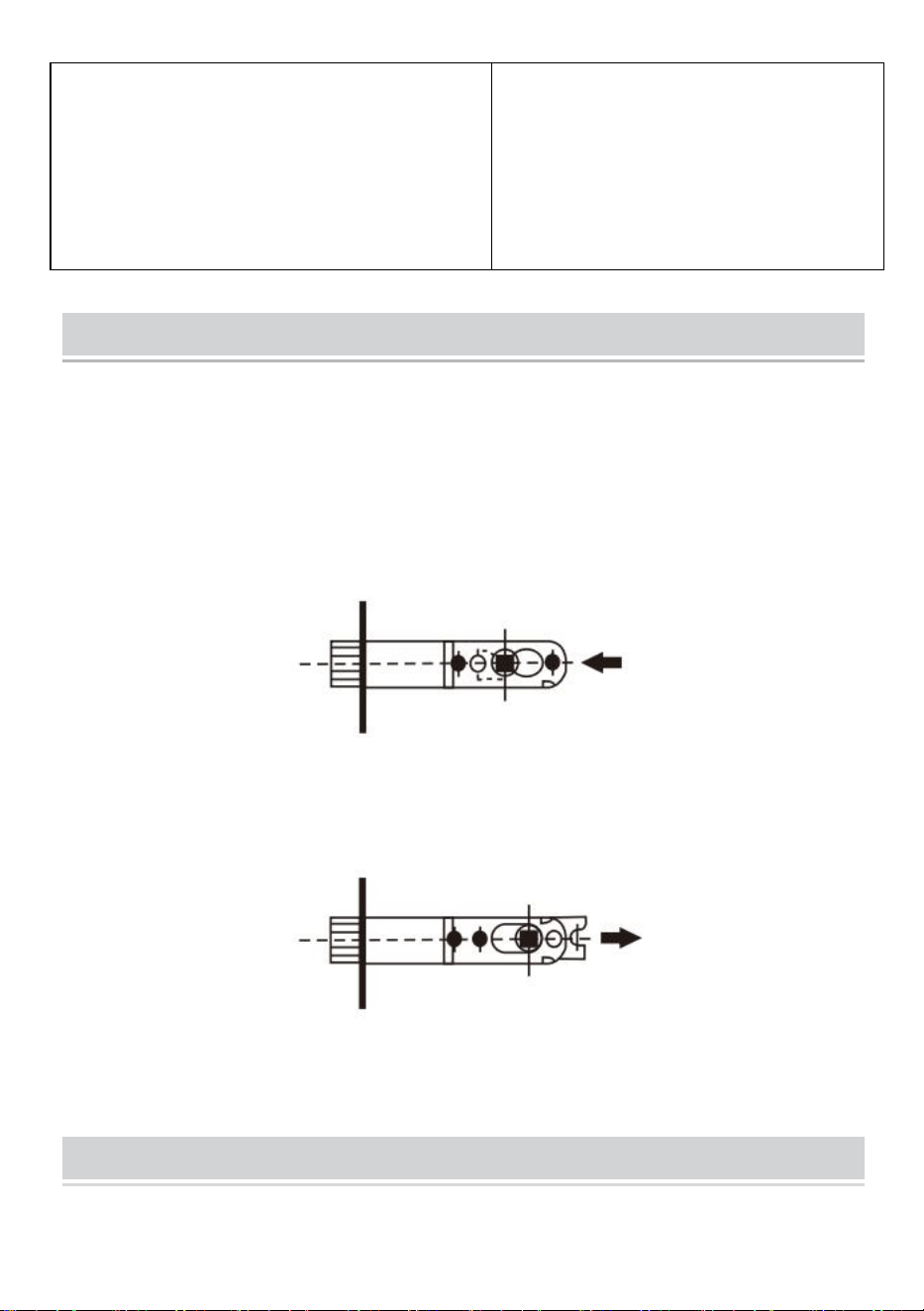
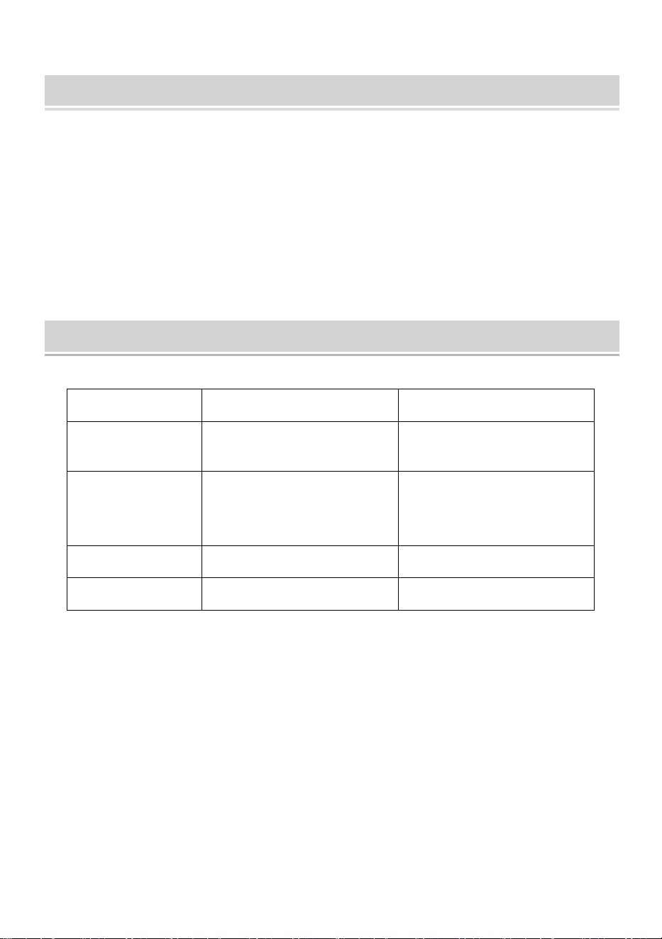
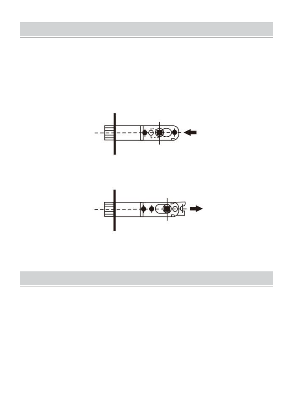
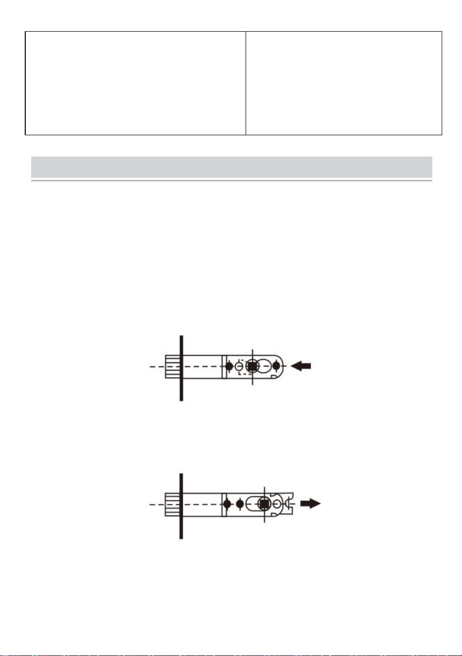
(1)Instructions For Adjustable Latch
For the adjustable latch, latch hole should be 1"(25mm)dia, and according to
centers of drilled 2-1/8"(54mm)dia, lockset hole. For either 2-3/8"(60mm) or
2-3/4"(70mm) backset. The method of adjustment is illustrated below:
①The turning wheel is pushed fully to the left for 2-3/8"(60mm) backset.
②
The turning wheel is pushed fully to the right for 2-3/4"(70mm) backset.
★
During the adjustment as above, Keeping two teeth of the turning wheel to
forward first.
MAINTENANCE
1.Do not strike with force to avoid damage to the latch and door frame.
2.If there is dirt, use a dry cloth to remove, do not scrub with chemicals such as
dishwashing liquid. Otherwise, it will destroy the protective film of exposed parts
and cause fading.
3.Periodically (half a year or once a year) or when the key is not smoothly inserted
and removed, graphite powder (pencil powder) can be added in the keyhole to
lubricate.
Product Parameter
Model
587+D101
3683+D101
Product Form
Spherical handle
Wave shaped handle
Apply to Door
Thickness
1-3/8 to 1-3/4
1-3/8 to 1-3/4
Colour
Silvery
Silvery
Material
SUS201、Kirsite、Brass
SUS201、Kirsite、Brass
Manufacturer: Shanghaimuxinmuyeyouxiangongsi
Address: Shuangchenglu 803nong11hao1602A-1609shi, baoshanqu, shanghai
200000 CN.
Imported to AUS: SIHAO PTY LTD. 1 ROKEVA STREETEASTWOOD NSW 2122
Australia
Imported to USA: Sanven Technology Ltd. Suite 250, 9166 Anaheim Place,
Rancho Cucamonga, CA 91730
REP
EC
E-CrossStu GmbH
Mainzer Landstr.69, 60329 Frankfurt am Main
.
REP
UK
YH CONSULTING LIMITED.
C/O YH Consulting Limited Office 147, Centurion House,
London Road, Staines-upon-Thames, Surrey, TW18 4AX


Techniczny Wsparcie i certyfikat gwarancji elektronicznej www.vevor.com/support
Zestawy zamków do drzwi
Instrukcja obsługi
MODEL: 5 8 7 +D 1 0 1 、 368 3 +D 1 0 1
We continue to be committed to provide you tools with competitive price.
"Save Half", "Half Price" or any other similar expressions used by us only represents an
estimate of savings you might benefit from buying certain tools with us compared to the major
top brands and does not necessarily mean to cover all categories of tools offered by us. You
are kindly reminded to verify carefully when you are placing an order with us if you are
actually saving half in comparison with the top major brands.
MODELE: 587+D101 MODELE: 3683+D101
★ Zdjęcie ma charakter poglądowy, proszę odnieść się do stanu faktycznego.
Have product questions? Need technical support? Please feel free to
contact us:
Technical Support and E-Warranty Certificate
www.vevor.com/support
NEED HELP? CONTACT US!
This is the original instruction, please read all manual instructions
carefully before operating. VEVOR reserves a clear interpretation of our
user manual. The appearance of the product shall be subject to the
product you received. Please forgive us that we won't inform you again if
there are any technology or software updates on our product.
Door Locksets
Ostrzeżenie: Aby zminimalizować ryzyko obrażeń, użytkownik
powinien uważnie przeczytać instrukcję obsługi.
Installation tools
Narzędzia wymagane do wymiany instalacji
Śrubokręt krzyżakowy
Dodatkowe narzędzia wymagane do nowej
instalacji
Taśma miernicza Wiertło wiertnicze 1 "
Dodatkowe narzędzia (jeśli potrzebne): dłuto, młotek,
ołówek, okulary ochronne.
Installation Instructions
(1) Wywierć otwory
a. Fold the template at the dotted line
and tape the template to the interior
side of the door at 34 to 48 inch Height.
b. Measure the thickness of the door
and mark the middle point of the door
thickness.
c. Mark the (60 or 70mm) hole center for
the backset.
Note: Make sure the two dots are at the
same height.
a. Drill a Dia. (54mm) hole for the lock
body.
b. Drill a Dia. (25mm) hole for the latch.
c. Insert the latch into the hole and mark
the outline of the faceplate.
d. Chisel a (3mm) deep hole for the
faceplate.
2⅛" Hole
Boring Saw
(2) Instalacja Instrukcje dotyczące zamka kulkowego lub zamka w kształcie fali
1.Zamontuj zatrzask
1. Zamontuj zasuwkę w pozycji „
górnej” do otworu w drzwiach.
2. Włóż i zabezpiecz za pomocą
śruby.
2. Zamontuj płytkę uderzeniową
Płytka zabezpieczająca przed
uderzeniem, jak na ilustracji,
zapobiegająca próbie wyważenia drzwi,
gdy są zamknięte.
3. Zamontuj jednostkę pokrętła
zewnętrznego
Zamontuj zewnętrzną jednostkę
pokrętła za pomocą prowadnic
śrub, pręta blokującego i trzpienia
włożonego w zatrzask, jak
pokazano na ilustracji.
4. Zamontuj jednostkę pokrętła
wewnętrznego .
1. Wsu ń prowadnice śrub, pręt
blokujący i wrzeciono do jednostki
wewnętrznej .
2. Włóż śruby i mocno je dokręć .
3 ) Instalacja Instrukcja obsługi zamka Zestaw zamków
Twój zatrzask jest fabrycznie ustawiony
na 2-3/8" (60 mm). Jeśli Twoje drzwi
wymagają 2-3/4" (70mm) Zatrzask,
wykonaj następujące kroki.
A. Trzymaj Zatrzask po prawej stronie
ręka tak widać otwory regulacyjne.Z
zamek skrętu w lewo płytkę w pozycji
zgodnej z ruchem wskazówek zegara.
Wyciągnij płytkę zatrzaskową w miarę
możliwości to pójdzie.
B. Odwróć się i zablokuj w 70mm
pozycja
1. Zainstaluj zatrzask
1. Zamontuj zasuwkę w pozycji „
górnej” do otworu w drzwiach.
2. Włóż i zabezpiecz za pomocą
śruby.
2. Montaż zespołu
zewnętrznego
1. Miejsce zespół cylindra przez
zewnętrzną osłonę cylindra i na
drzwiach, upewniając się, że ostrze
momentu obrotowego jest prawidłowo
ustawione w korbie zamka.
2. Włóż klucz do cylindra i przekręć, aż
rygiel będzie odsłonięty. Uwaga:
Dziurka od klucza musi być w pozycji „
3. Montaż zespołu wewnętrznego
Sprawdź, czy zamek zasuwkowy
jest w pozycji zablokowanej.
Umieść zespół pokrętła na ostrzu
momentu obrotowego i wyrównaj
otwory na śruby. Pokrętło będzie w
pozycji „górnej”, dzięki czemu
będziesz mógł zobaczyć otwory na
śruby. Dokręć długie śruby
maszynowe.
w dół ” , jak pokazano.
Note
( 1 ) Instrukcja dotycząca regulowanego zatrzasku
W przypadku regulowanego zatrzasku otwór zatrzasku powinien mieć średnicę
1"(25mm) i zgodnie z wywierconymi środkami 2-1/8"(54mm) otwór zamka. Do
odsadzenia 2-3/8"(60mm) lub 2-3/4"(70mm). Poniżej przedstawiono metodę
regulacji:
①Koło obrotowe należy przesunąć maksymalnie w lewo, aby uzyskać cofnięcie o
2-3/8" (60 mm).
② Koło obrotowe należy przesunąć maksymalnie w prawo, aby uzyskać
odsunięcie 2-3/4" (70 mm).
★
Podczas regulacji jak powyżej, najpierw ustaw dwa zęby koła obrotowego do
przodu.
MAINTENANCE
1. Nie uderzaj z dużą siłą, aby uniknąć uszkodzenia zatrzasku i ościeżnicy.
2. Jeśli jest brud, usuń go suchą szmatką, nie szoruj środkami chemicznymi,
takimi jak płyn do mycia naczyń. W przeciwnym razie zniszczy to warstwę
ochronną odsłoniętych części i spowoduje blaknięcie.
3. Okresowo (co pół roku lub raz na rok) lub gdy wkładanie i wyjmowanie klucza
nie przebiega płynnie, do zamka można dodać proszek grafitowy (proszek
ołówkowy) w celu nasmarowania.
Product Parameter
Model
587+D101
3683+D101
Formularz
produktu
Uchwyt kulisty
Uchwyt w kształcie fali
Zastosuj do
grubości drzwi
1-3/8 do 1-3/4
1-3/8 do 1-3/4
Kolor
Srebrzysty
Srebrzysty
Tworzywo
SUS201, Kirsyt, Mosiądz
SUS201, Kirsyt, Mosiądz
Producent: Shanghaimuxinmuyeyouxiangongsi
Adres: Shuangchenglu 803nong11hao1602A-1609shi, baoshanqu, szanghaj
200000 CN.
Importowane do AUS: SIHAO PTY LTD. 1 ROKEVA STREETEASTWOOD NSW
2122 Australia
Importowane do USA: Sanven Technology Ltd. Suite 250, 9166 Anaheim Place,
Rancho Cucamonga, CA 91730
REP
EC
E-CrossStu GmbH
Mainzer Landstr.69, 60329 Frankfurt am Main.
REP
UK
YH CONSULTING LIMITED.
C/O YH Consulting Limited Office 147, Centurion House,
London Road, Staines-upon-Thames, Surrey, TW18 4AX


Technisch Support und E-Garantie-Zertifikat www.vevor.com/support
Türschloss-Sets
Bedienungsanleitung
MODELL: 587+D 1 0 1 、 3683+D 1 0 1
We continue to be committed to provide you tools with competitive price.
"Save Half", "Half Price" or any other similar expressions used by us only represents an
estimate of savings you might benefit from buying certain tools with us compared to the major
top brands and does not necessarily mean to cover all categories of tools offered by us. You
are kindly reminded to verify carefully when you are placing an order with us if you are
actually saving half in comparison with the top major brands.

MODELL: 587+D101 MODELL: 3683+D101
★ Das Bild dient nur als Referenz. Bitte beachten Sie das tatsächliche Bild.
Have product questions? Need technical support? Please feel free to
contact us:
Technical Support and E-Warranty Certificate
www.vevor.com/support
NEED HELP? CONTACT US!
This is the original instruction, please read all manual instructions
carefully before operating. VEVOR reserves a clear interpretation of our
user manual. The appearance of the product shall be subject to the
product you received. Please forgive us that we won't inform you again if
there are any technology or software updates on our product.
Door Locksets
Warnung: Um das Verletzungsrisiko zu verringern, muss der
Benutzer die Bedienungsanleitung sorgfältig lesen.
Installation tools
Für die Ersatzinstallation erforderliche
Werkzeuge
Kreuzschlitzschraubendreher
Für die Neuinstallation sind zusätzlich
Werkzeuge erforderlich
Maßband 1 " Lochbohrer
Zusätzliche Werkzeuge (falls erforderlich): Meißel,
Hammer, Bleistift, Schutzbrille.
Installation Instructions
(1) Löcher bohren
a. Fold the template at the dotted line
and tape the template to the interior
side of the door at 34 to 48 inch Height.
b. Measure the thickness of the door
and mark the middle point of the door
thickness.
c. Mark the (60 or 70mm) hole center for
the backset.
Note: Make sure the two dots are at the
same height.
2⅛" Hole
Boring Saw
(2) Installation Anleitung für Kugelschloss oder wellenförmiges Schloss
1.Installieren Sie den Riegel
1.Riegelriegel installieren
in"oben"Position ins Türloch.
2.Einstecken und sichern mit
Schrauben.
2.Schließblech installieren
Schließblech gegen Türöffner wie
abgebildet, verhindert Aufbrechen bei
geschlossener Tür.
3.Außenknaufeinheit installieren
Installieren Sie die äußere
Knaufeinheit mit
Schraubenführungen,
4. Installieren Sie die innere
Knopfeinheit .
1. Schraubenführungen,
Verriegelungsstange und Spindel in die
Inneneinheit einrasten lassen. .
a. Drill a Dia. (54mm) hole for the lock
body.
b. Drill a Dia. (25mm) hole for the latch.
c. Insert the latch into the hole and mark
the outline of the faceplate.
d. Chisel a (3mm) deep hole for the
faceplate.
Verriegelungsstange und Spindel,
die wie abgebildet in den Riegel
einrastet.
2. Schrauben einsetzen und gut
festziehen .
(3 ) Installation Anleitung für D eadbolt Schlosssatz
Ihr Riegel ist werkseitig auf
2-3/8"(60mm) eingestellt. Wenn Ihre Tür
einen 2-3/4" benötigt (70 mm) Latch,
befolgen Sie diese Schritte.
A.Halten Riegel rechts einrasten Hand
so Sie können Einstelllöcher sehen.Mit
Verriegelung mit Linksdrehung Platte
im Uhrzeigersinn drehen . Riegelplatte
herausziehen von sase soweit es wird
gehen.
B.Kehren Sie um und Einrasten in
70mm Position
1. Installieren Sie den Riegel
1.Riegelriegel installieren
in"oben"Position ins Türloch.
2.Einstecken und sichern mit
Schrauben.
2. Außenbaugruppe
installieren
1.Platz Führen Sie die
Zylinderbaugruppe durch den äußeren
Zylinderschutz und an der Tür und
3. Innenbaugruppe installieren
Stellen Sie sicher, dass sich der
Riegel in der verriegelten Position
befindet.
Platzieren Sie die
stellen Sie sicher, dass das
Drehmomentblatt richtig in der
Verriegelungskurbel positioniert ist.
2. Stecken Sie den Schlüssel in den
Zylinder und drehen Sie ihn, bis der
Riegel freiliegt. Hinweis: Das
Schlüsselloch muss sich wie gezeigt in
der Position „unten“ befinden .
Daumendrehvorrichtung auf dem
Drehmomentblatt und richten Sie
die Schraubenlöcher aus. Der
Daumenknopf befindet sich in der
Position „oben“, sodass Sie die
Schraubenlöcher sehen können.
Ziehen Sie lange
Maschinenschrauben fest .
Note
( 1 ) Anleitung für verstellbaren Riegel
Für den verstellbaren Riegel sollte das Riegelloch einen Durchmesser von 1" (25
mm) haben und das Schlossloch sollte entsprechend der Mittenbohrung 2-1/8" (54
mm) Durchmesser haben. Für entweder 2-3/8" (60 mm) oder 2-3/4" (70 mm)
Dornmaß. Die Einstellmethode ist unten dargestellt:
①Das Drehrad wird für einen Rücksprung von 2-3/8 Zoll (60 mm) ganz nach links
gedrückt.
② Das Drehrad wird für einen Dornabstand von 2-3/4 Zoll (70 mm) ganz nach
rechts gedrückt.
★
Halten Sie bei der Einstellung wie oben beschrieben zunächst zwei Zähne des
Drehrads nach vorne.
MAINTENANCE
1. Schlagen Sie nicht mit Gewalt zu, um Schäden am Riegel und Türrahmen zu
vermeiden.
2. Entfernen Sie Schmutz mit einem trockenen Tuch. Verwenden Sie zum
Schrubben keine Chemikalien wie Spülmittel. Andernfalls wird der Schutzfilm
freiliegender Teile zerstört und es kommt zum Verblassen.
3. In regelmäßigen Abständen (halbjährlich oder einmal jährlich) oder wenn sich
der Schlüssel nicht reibungslos einstecken oder herausziehen lässt, kann zur
Schmierung Graphitpulver (Bleistiftpulver) in das Schlüsselloch gegeben werden.
Product Parameter
Modell
587+D101
3683+D101
Produktform
Kugelförmiger Griff
Wellenförmiger Griff
Auf Türstärke
anwenden
1-3/8 bis 1-3/4
1-3/8 bis 1-3/4
Farbe
Silbrig
Silbrig
Material
SUS201, Kirsite, Messing
SUS201, Kirsite, Messing
Hersteller: Shanghaimuxinmuyeyouxiangongsi
Adresse: Shuangchenglu 803nong11hao1602A-1609shi, baoshanqu, Shanghai
200000 CN.
Nach AUS importiert: SIHAO PTY LTD. 1 ROKEVA STREETEASTWOOD NSW

2122 Australien
Importiert in die USA: Sanven Technology Ltd. Suite 250, 9166 Anaheim Place,
Rancho Cucamonga, CA 91730
REP
EC
E-CrossStu GmbH
Mainzer Landstr.69, 60329 Frankfurt am Main.
REP
UK
YH CONSULTING LIMITED.
C/O YH Consulting Limited Office 147, Centurion House,
London Road, Staines-upon-Thames, Surrey, TW18 4AX


Technique Certificat d'assistance et de garantie électronique
www.vevor.com/support
Serrures de porte
Manuel d'instructions
MODÈLE: 587+D101 、 3683+D101
We continue to be committed to provide you tools with competitive price.
"Save Half", "Half Price" or any other similar expressions used by us only represents an
estimate of savings you might benefit from buying certain tools with us compared to the major
top brands and does not necessarily mean to cover all categories of tools offered by us. You
are kindly reminded to verify carefully when you are placing an order with us if you are
actually saving half in comparison with the top major brands.

MODÈLE : 587+D101 MODÈLE : 3683+D101
★ L'image est à titre de référence uniquement, veuillez vous référer à la réalité.
Have product questions? Need technical support? Please feel free to
contact us:
Technical Support and E-Warranty Certificate
www.vevor.com/support
NEED HELP? CONTACT US!
This is the original instruction, please read all manual instructions
carefully before operating. VEVOR reserves a clear interpretation of our
user manual. The appearance of the product shall be subject to the
product you received. Please forgive us that we won't inform you again if
there are any technology or software updates on our product.
Door Locksets

Avertissement - Pour réduire le risque de blessure, l'utilisateur
doit lire attentivement le manuel d'instructions.
Installation tools
Outils requis pour l'installation du
remplacement
Tournevis cruciforme
Outils supplémentaires requis pour une
nouvelle installation
Mètre à ruban Foret à aléser de 1 po
Outils supplémentaires (si nécessaire) : ciseau,
marteau, crayon, lunettes de sécurité.
Installation Instructions
(1) Percer des trous
a. Fold the template at the dotted line
and tape the template to the interior
side of the door at 34 to 48 inch Height.
b. Measure the thickness of the door
and mark the middle point of the door
thickness.
c. Mark the (60 or 70mm) hole center for
the backset.
Note: Make sure the two dots are at the
same height.
2⅛" Hole
Boring Saw
(2) Installation Instructions pour serrure à bille ou serrure à forme ondulée
1.Installez le loquet
1.Installer le loquet à pêne dormant
en position "haute" dans le trou de
la porte.
2.Insérez et fixez avec vis.
2.Installer la gâche
Gâche contre gâche comme illustré,
empêchant le forçage lorsque la porte
est fermée.
3.Installer l'unité de bouton
extérieur
Installez l'unité de bouton extérieur
avec les guides à vis, la barre de
4. Installer l'unité de bouton
intérieure .
1. Engagez les guides à vis, la barre de
verrouillage et la broche dans l'unité
intérieure .
a. Drill a Dia. (54mm) hole for the lock
body.
b. Drill a Dia. (25mm) hole for the latch.
c. Insert the latch into the hole and mark
the outline of the faceplate.
d. Chisel a (3mm) deep hole for the
faceplate.
verrouillage et la broche engagées
dans le loquet comme illustré.
2. Insérez les vis et serrez fermement .
3 ) Installation Instructions pour le pêne dormant Serrure
Votre loquet est réglé en usine pour
2-3/8" (60 mm) Si votre porte nécessite
un 2-3/4" (70 mm) Loquet, suivez ces
étapes.
A. Tenir Accrochez-vous à votre droite
main donc vous pouvez voir les trous
de réglage.Avec loquet tournant à
gauche plaque en position dans le sens
des aiguilles d'une montre.Retirez la
plaque de verrouillage de sase dans la
mesure où ça ira.
B.Retournez-vous et verrouiller en 70
mm position
1. Installez le loquet
1.Installer le loquet à pêne dormant
en position "haute" dans le trou de
la porte.
2.Insérez et fixez avec vis.
2. Installer l'assemblage
extérieur
1. Lieu assemblage du cylindre à
travers la protection extérieure du
cylindre et sur la porte en s'assurant
que la lame de couple est correctement
3. Installer l'assemblage intérieur
Assurez-vous que le pêne dormant
est en position verrouillée.
Placez l'assemblage du bouton
rotatif sur la lame de couple et
alignez les trous de vis. Le bouton
positionnée dans la manivelle du
loquet.
2. Placez la clé dans le cylindre et
tournez-la jusqu'à ce que le pêne
dormant soit exposé. Remarque : le
trou de serrure doit être en position
« abaissé » comme indiqué.
rotatif sera en position « haute »
pour que vous puissiez voir les
trous de vis. Serrez les longues vis
de la machine.
Note
( 1 ) Instructions pour le loquet réglable
Pour le loquet réglable, le trou du loquet doit avoir un diamètre de 25 mm (1 po) et
être conforme aux centres des trous de serrure percés de 54 mm (2-1/8 po) de
diamètre. Pour un écartement de 60 mm (2-3/8 po) ou de 70 mm (2-3/4 po). La
méthode de réglage est illustrée ci-dessous :
①La molette rotative est poussée complètement vers la gauche pour un
écartement de 2-3/8" (60 mm).
② La molette de rotation est poussée complètement vers la droite pour un
écartement de 2-3/4" (70 mm).

★
Lors du réglage comme ci-dessus, gardez d'abord les deux dents de la roue
tournante vers l'avant.
MAINTENANCE
1. Ne frappez pas avec force pour éviter d’endommager le loquet et le cadre de la
porte.
2. S'il y a de la saleté, utilisez un chiffon sec pour l'enlever, ne frottez pas avec des
produits chimiques tels que du liquide vaisselle. Sinon, cela détruirait le film
protecteur des parties exposées et provoquerait une décoloration.
3. Périodiquement (tous les six mois ou une fois par an) ou lorsque la clé n'est pas
insérée et retirée en douceur, de la poudre de graphite (poudre de crayon) peut
être ajoutée dans le trou de serrure pour lubrifier.
Product Parameter
Modèle
587+D101
3683+D101
Fiche produit
Poignée sphérique
Poignée en forme de
vague
Appliquer à
l'épaisseur de la
porte
1-3/8 à 1-3/4
1-3/8 à 1-3/4
Couleur
Argenté
Argenté
Matériel
SUS201, Kirsite, Laiton
SUS201, Kirsite, Laiton
Fabricant : Shanghaimuxinmuyeyouxiangongsi
Adresse : Shuangchenglu 803nong11hao1602A-1609shi, baoshanqu, shanghai
200000 CN.
Importé en Australie : SIHAO PTY LTD. 1 ROKEVA STREETEASTWOOD NSW
2122 Australie
Importé aux États-Unis : Sanven Technology Ltd. Suite 250, 9166 Anaheim
Place, Rancho Cucamonga, CA 91730
REP
EC
E-CrossStu GmbH
Mainzer Landstr.69, 60329 Frankfurt am Main.
REP
UK
YH CONSULTING LIMITED.
C/O YH Consulting Limited Office 147, Centurion House,
London Road, Staines-upon-Thames, Surrey, TW18 4AX


Technisch Ondersteuning en E-garantiecertificaat www.vevor.com/support
Deurslotensets
Gebruiksaanwijzing
MODEL: 5 8 7 +D 1 0 1 、 368 3 +D 1 0 1
We continue to be committed to provide you tools with competitive price.
"Save Half", "Half Price" or any other similar expressions used by us only represents an
estimate of savings you might benefit from buying certain tools with us compared to the major
top brands and does not necessarily mean to cover all categories of tools offered by us. You
are kindly reminded to verify carefully when you are placing an order with us if you are
actually saving half in comparison with the top major brands.

MODEL: 587+D101 MODEL: 3683+D101
★ De afbeelding is alleen ter referentie, raadpleeg de werkelijke versie.
Have product questions? Need technical support? Please feel free to
contact us:
Technical Support and E-Warranty Certificate
www.vevor.com/support
NEED HELP? CONTACT US!
This is the original instruction, please read all manual instructions
carefully before operating. VEVOR reserves a clear interpretation of our
user manual. The appearance of the product shall be subject to the
product you received. Please forgive us that we won't inform you again if
there are any technology or software updates on our product.
Door Locksets

Waarschuwing: om het risico op letsel te verkleinen, moet de
gebruiker de gebruiksaanwijzing zorgvuldig lezen.
Installation tools
Benodigde gereedschappen voor
vervangingsinstallatie
Kruiskopschroevendraaier
Extra gereedschap vereist voor nieuwe
installatie
Meetlint 1 " Gatboor
Extra gereedschap (indien nodig): beitel, hamer,
potlood, veiligheidsbril.
Installation Instructions
(1) Boorgaten
a. Fold the template at the dotted line
and tape the template to the interior
side of the door at 34 to 48 inch Height.
b. Measure the thickness of the door
and mark the middle point of the door
thickness.
c. Mark the (60 or 70mm) hole center for
the backset.
Note: Make sure the two dots are at the
same height.
2⅛" Hole
Boring Saw

(2) Installatie Instructies voor een kogelvormig slot of een golfvormig slot
1. Installeer de grendel
1. Installeer de nachtschoot in de
"omhoog"positie in het deurgat.
2. Plaats en bevestig met
schroeven.
2. Sluitplaat installeren
Sluitplaat tegen de sluitplaat zoals
afgebeeld, voorkomt forceren wanneer
de deur gesloten is.
3. Installeer de buitenknopeenheid
Monteer de buitenknopeenheid met
de schroefgeleiders, de
vergrendelingsstang en de spindel
4. Installeer de binnenknopeenheid .
1. Plaats de schroefgeleiders, de
vergrendelingsstang en de spindel in
de binnenunit .
2. Plaats de schroeven en draai ze
a. Drill a Dia. (54mm) hole for the lock
body.
b. Drill a Dia. (25mm) hole for the latch.
c. Insert the latch into the hole and mark
the outline of the faceplate.
d. Chisel a (3mm) deep hole for the
faceplate.
in de grendel zoals afgebeeld.
stevig vast .
3 ) Installatie Instructies voor de nachtschoot Slotset
Uw grendel is in de fabriek ingesteld op
2-3/8" (60 mm). Als uw deur een
2-3/4"-grendel nodig heeft, (70mm)
Latch, volg deze stappen.
A.Houd Vergrendeling in uw
rechterhand hand dus je kunt de
afstelgaten zien.Met linksdraaiende
grendel plaat in de richting van de klok .
Trek de vergrendelingsplaat eruit. van
sase voor zover het zal gaan.
B. Draai je om en vergrendelen in 70mm
positie
1. Installeer de grendel
1. Installeer de nachtschoot in de
"omhoog"positie in het deurgat.
2. Plaats en bevestig met
schroeven.
2. Buitenmontage
installeren
1. Plaats cilindermontage via de
buitenste cilinderbescherming en op de
deur. Zorg ervoor dat het torsieblad
correct in de vergrendelingskruk is
geplaatst.
3. Interieurmontage installeren
Zorg ervoor dat de nachtschoot in
de vergrendelde stand staat.
Plaats de duimdraai-eenheid op het
torsieblad en lijn de schroefgaten
uit. De duimknop staat in de
"omhoog" positie, zodat u de
2. Steek de sleutel in de cilinder en
draai totdat de nachtschoot zichtbaar
is. Let op: het sleutelgat moet in de
"omlaag"-positie staan, zoals
afgebeeld.
schroefgaten kunt zien. Draai de
lange machineschroeven vast
Note
( 1 ) Instructies voor een verstelbare vergrendeling
Voor de verstelbare grendel moet het grendelgat 1"(25mm)dia zijn, en volgens de
middelpunten van de geboorde 2-1/8"(54mm)dia, slotgat. Voor 2-3/8"(60mm) of
2-3/4"(70mm) backset. De aanpassingsmethode wordt hieronder geïllustreerd:
①Druk het draaiwiel volledig naar links voor een doornmaat van 2-3/8"(60mm).
② Het draaiwiel wordt volledig naar rechts geduwd voor een doornmaat van
2-3/4"(70 mm).
★
Houd tijdens de bovenstaande afstelling de twee tanden van het draaiwiel eerst
naar voren.
MAINTENANCE
1. Sla niet met geweld om schade aan de grendel en het deurkozijn te voorkomen.
2. Als er vuil is, gebruik dan een droge doek om het te verwijderen, schrob niet met
chemicaliën zoals afwasmiddel. Anders zal het de beschermende film van
blootgestelde delen vernietigen en vervaging veroorzaken.
3. Periodiek (een half jaar of eens per jaar) of wanneer de sleutel niet soepel in en
uit het slot gaat, kan er grafietpoeder (potloodpoeder) in het sleutelgat worden
gedaan om het te smeren.
Product Parameter
Model
587+D101
3683+D101
Productformulie
r
Bolvormige handgreep
Golvende handgreep
Toepassen op
deurdikte
1-3/8 tot 1-3/4
1-3/8 tot 1-3/4
Kleur
Zilverachtig
Zilverachtig
Materiaal
SUS201、Kirsite、Messing
SUS201、Kirsite、Messing
Fabrikant: Shanghaimuxinmuyeyouxiangongsi
Adres: Shuangchenglu 803nong11hao1602A-1609shi, baoshanqu, shanghai
200000 CN.
Geïmporteerd naar AUS: SIHAO PTY LTD. 1 ROKEVA STREETEASTWOOD
NSW 2122 Australië
Geïmporteerd naar de VS: Sanven Technology Ltd. Suite 250, 9166 Anaheim
Place, Rancho Cucamonga, CA 91730
REP
EC
E-CrossStu GmbH
Mainzer Landstr.69, 60329 Frankfurt am Main.

REP
UK
YH CONSULTING LIMITED.
C/O YH Consulting Limited Office 147, Centurion House,
London Road, Staines-upon-Thames, Surrey, TW18 4AX


Técnico Soporte y certificado de garantía electrónica www.vevor.com/support
Cerraduras de puertas
Manual de instrucciones
MODELO: 5 8 7 + D101 、 3 6 8 3 + D 1 0 1
We continue to be committed to provide you tools with competitive price.
"Save Half", "Half Price" or any other similar expressions used by us only represents an
estimate of savings you might benefit from buying certain tools with us compared to the major
top brands and does not necessarily mean to cover all categories of tools offered by us. You
are kindly reminded to verify carefully when you are placing an order with us if you are
actually saving half in comparison with the top major brands.

MODELO: 587+D101 MODELO: 3683+D101
★ La imagen es solo de referencia, consulte la real.
Have product questions? Need technical support? Please feel free to
contact us:
Technical Support and E-Warranty Certificate
www.vevor.com/support
NEED HELP? CONTACT US!
This is the original instruction, please read all manual instructions
carefully before operating. VEVOR reserves a clear interpretation of our
user manual. The appearance of the product shall be subject to the
product you received. Please forgive us that we won't inform you again if
there are any technology or software updates on our product.
Door Locksets

Advertencia: Para reducir el riesgo de lesiones, el usuario
debe leer atentamente el manual de instrucciones.
Installation tools
Herramientas necesarias para la instalación
de reemplazo
Destornillador Phillips
Herramientas adicionales necesarias para
una nueva instalación
Cinta métrica Broca para perforar agujeros de 1 "
Herramientas adicionales (si es necesario): cincel,
martillo, lápiz, gafas de seguridad.
Installation Instructions
(1) Perforar agujeros
a. Fold the template at the dotted line
and tape the template to the interior
side of the door at 34 to 48 inch Height.
b. Measure the thickness of the door
and mark the middle point of the door
thickness.
c. Mark the (60 or 70mm) hole center for
the backset.
Note: Make sure the two dots are at the
same height.
2⅛" Hole
Boring Saw
(2) Instalación Instrucciones de cerradura de bola o cerradura en forma de onda
1. Instale el pestillo
1. Instale el pestillo del cerrojo en
posición "arriba" En el agujero de
la puerta.
2.Insertar y asegurar con tornillos.
2.Instalar la placa de impacto
Placa de impacto contra cerradero
como se ilustra, evitando forzar la
puerta cuando está cerrada.
3. Instale la unidad de perilla
exterior
Instale la unidad de perilla exterior
con guías de tornillos, barra de
4. Instalar la unidad de perilla interior .
1. Encaje las guías de tornillo, la barra
de bloqueo y el husillo en la unidad
interior .
2. Inserte los tornillos y apriételos
a. Drill a Dia. (54mm) hole for the lock
body.
b. Drill a Dia. (25mm) hole for the latch.
c. Insert the latch into the hole and mark
the outline of the faceplate.
d. Chisel a (3mm) deep hole for the
faceplate.
bloqueo y eje enganchados en el
pestillo como se ilustra.
firmemente .
3 ) Instalación Instrucciones del cerrojo Juego de cerradura
Su pestillo está configurado de fábrica
para 2-3/8" (60 mm). Si su puerta
requiere un 2-3/4" (70 mm) Pestillo, siga
estos pasos.
A.Mantener Enganche su pestillo
derecho mano asi Puedes ver los
agujeros de ajuste. pestillo giratorio a la
izquierda Placa en posición en el
sentido de las agujas del reloj. Tire de la
placa del pestillo hacia afuera . por
supuesto en cuanto a se ira
B.Date la vuelta y bloquear en 70 mm
posición
1. Instale el pestillo
1. Instale el pestillo del cerrojo en
posición "arriba" En el agujero de
la puerta.
2.Insertar y asegurar con tornillos.
2. Instalación del conjunto
exterior
1. Lugar Ensamblaje del cilindro a
través de la protección exterior del
cilindro y en la puerta, asegurándose de
que la cuchilla de torsión esté colocada
3. Instalación del conjunto interior
Asegúrese de que el cerrojo esté
en la posición bloqueada.
Coloque el conjunto giratorio
sobre la cuchilla de torsión y alinee
los orificios de los tornillos. La
correctamente en la manivela del
pestillo.
2. Coloque la llave en el cilindro y gírela
hasta que el cerrojo quede expuesto.
Nota: La cerradura debe estar en la
posición "abajo", como se muestra .
perilla del pulgar estará en la
posición "arriba" para que pueda
ver los orificios de los tornillos.
Apriete los tornillos largos para
máquina.
Note
( 1 ) Instrucciones para el pestillo ajustable
Para el pestillo ajustable, el orificio del pestillo debe tener un diámetro de 1" (25
mm) y, de acuerdo con los centros de los orificios perforados para la cerradura, un
diámetro de 2-1/8" (54 mm). Para un retroceso de 2-3/8" (60 mm) o 2-3/4" (70
mm). El método de ajuste se ilustra a continuación:
①La rueda giratoria se empuja completamente hacia la izquierda para lograr un
retroceso de 2-3/8" (60 mm).
② La rueda giratoria se empuja completamente hacia la derecha para lograr un
retroceso de 2-3/4" (70 mm).
★
Durante el ajuste como se indica arriba, mantenga los dos dientes de la rueda
giratoria hacia adelante primero.
MAINTENANCE
1. No golpee con fuerza para evitar dañar el pestillo y el marco de la puerta.
2. Si hay suciedad, utilice un paño seco para eliminarla, no frote con productos
químicos como el lavavajillas, ya que se destruirá la película protectora de las
partes expuestas y se decolorará.
3. Periódicamente (semestre o una vez al año) o cuando la llave no se inserta y se
retira con suavidad, se puede agregar polvo de grafito (polvo de lápiz) en el ojo de
la cerradura para lubricar.
Product Parameter
Modelo
587+D101
3683+D101
Forma del
producto
Mango esférico
Mango en forma de onda
Aplicar al
espesor de la
puerta
1-3/8 a 1-3/4
1-3/8 a 1-3/4
Color
Plateado
Plateado
Material
SUS201, Kirsite, latón
SUS201, Kirsite, latón
Fabricante: Shanghaimuxinmuyeyouxiangongsi
Dirección: Shuangchenglu 803nong11hao1602A-1609shi, baoshanqu, shanghai
200000 CN.
Importado a AUS: SIHAO PTY LTD. 1 ROKEVA STREETEASTWOOD NSW
2122 Australia
Importado a EE. UU.: Sanven Technology Ltd. Suite 250, 9166 Anaheim Place,

Rancho Cucamonga, CA 91730
REP
EC
E-CrossStu GmbH
Mainzer Landstr.69, 60329 Frankfurt am Main.
REP
UK
YH CONSULTING LIMITED.
C/O YH Consulting Limited Office 147, Centurion House,
London Road, Staines-upon-Thames, Surrey, TW18 4AX


Teknisk Support och e-garanticertifikat www.vevor.com/support
Dörrlås
Instruktionsmanual
MODELL: 587+D101 、 3683+D101
We continue to be committed to provide you tools with competitive price.
"Save Half", "Half Price" or any other similar expressions used by us only represents an
estimate of savings you might benefit from buying certain tools with us compared to the major
top brands and does not necessarily mean to cover all categories of tools offered by us. You
are kindly reminded to verify carefully when you are placing an order with us if you are
actually saving half in comparison with the top major brands.

MODELL: 587+D101 MODELL: 3683+D101
★ Bilden är endast för referens, se den faktiska.
Have product questions? Need technical support? Please feel free to
contact us:
Technical Support and E-Warranty Certificate
www.vevor.com/support
NEED HELP? CONTACT US!
This is the original instruction, please read all manual instructions
carefully before operating. VEVOR reserves a clear interpretation of our
user manual. The appearance of the product shall be subject to the
product you received. Please forgive us that we won't inform you again if
there are any technology or software updates on our product.
Door Locksets
Varning - För att minska risken för skada måste användaren
läsa instruktionerna noggrant.
Installation tools
Verktyg som krävs för ersättningsinstallation
Phillips skruvmejsel
Extra verktyg som krävs för nyinstallation
Måttband 1 " hålborrbit
Ytterligare verktyg (om det behövs): mejsel, hammare,
penna, skyddsglasögon.
Installation Instructions
(1) Borra hål
a. Fold the template at the dotted line
and tape the template to the interior
side of the door at 34 to 48 inch Height.
b. Measure the thickness of the door
and mark the middle point of the door
thickness.
c. Mark the (60 or 70mm) hole center for
the backset.
Note: Make sure the two dots are at the
same height.
a. Drill a Dia. (54mm) hole for the lock
body.
b. Drill a Dia. (25mm) hole for the latch.
c. Insert the latch into the hole and mark
the outline of the faceplate.
d. Chisel a (3mm) deep hole for the
faceplate.
2⅛" Hole
Boring Saw
(2)I nstallation I nstruktioner för kullåsset eller vågformat låsset
1. Installera spärren
1. Installera bultlåset i "upp" läge in
i dörrhålet.
2.Sätt i och säkra med skruvar.
2. Installera slagplattan
Slagplatta mot slag enligt bilden,
förhindrar forcering när dörren är
stängd.
3. Installera den yttre vredenheten
Installera utvändig knoppenhet
med skruvstyrningar, låsstång och
spindel i ingrepp med spärren
enligt bilden.
4. Installera insidan av vredenheten .
1. Sätt i skruvstyrningar, låsstång och
spindel i insidan av enheten. .
2. Sätt i skruvarna och dra åt ordentligt .
(3) I nstallation I nstruktioner för D eadbolt Låsset
Din spärr är fabriksinställd för 2-3/8" (60
mm) om din dörr kräver en 2-3/4" (70
mm) Spärr, följ dessa steg.
A. Håll Spärr i din högra sida hand så
du kan se justeringshål.Med vänster
vrid spärren plåt i medurs läge . dra ut
spärrplåten av sase så långt som det
kommer att gå.
B. Vänd tillbaka och lås i 70 mm placera
1. Installera spärren
1. Installera bultlåset i "upp" läge
in i dörrhålet.
2.Sätt i och säkra med skruvar.
2.
Installera den yttre
enheten
1.Plats cylindermontering genom det
yttre cylinderskyddet och på dörren och
se till att vridmomentbladet är korrekt
placerat i spärrveven.
2. Sätt i nyckeln i cylindern och vrid tills
Deadbolt är exponerad. Obs:
Nyckelhålet måste vara i läge "nedåt n "
enligt bilden.
3.
Installera den inre delen
Se till att Deadbolt är i låst läge.
Placera tumsvängningsenheten på
vridmomentbladet och rikta in
skruvhålen. Tumvredet kommer att
vara i "upp"-läget så att du kan se
skruvhålen. Dra åt långa
maskinskruvar
Note
(1)I nstruktioner F eller A justerbar L atch
För den justerbara spärren ska spärrhålet vara 1" (25 mm) dia, och enligt mitten av
borrat 2-1/8" (54 mm) dia, låsset hål. För antingen 2-3/8"(60mm) eller
2-3/4"(70mm) bakstycke. Justeringsmetoden illustreras nedan:
①Det vridande hjulet skjuts helt åt vänster för 2-3/8" (60 mm) backset.
②
Det vridande hjulet skjuts helt åt höger för 2-3/4" (70 mm) backset.
★
Under justeringen enligt ovan, Håll två tänder på det vridande hjulet framåt
först.
MAINTENANCE
1. Slå inte till med våld för att undvika skador på spärren och dörrkarmen.
2. Om det finns smuts, använd en torr trasa för att ta bort, skrubba inte med
kemikalier som diskmedel. Annars kommer det att förstöra skyddsfilmen på utsatta
delar och orsaka blekning.
3. Med jämna mellanrum (ett halvår eller en gång om året) eller när nyckeln inte är
smidigt insatt och borttagen, kan grafitpulver (pennpulver) tillsättas i nyckelhålet
för att smörja.
Product Parameter
Modell
587+D101
3683+D101
Produktform
Sfäriskt handtag
Vågformat handtag
Applicera på
Dörrtjocklek
1-3/8 till 1-3/4
1-3/8 till 1-3/4
Färg
Silverren
Silverren
Material
SUS201、Kirsite、Mässing
SUS201、Kirsite、Mässing
Tillverkare: Shanghaimuxinmuyeyouxiangongsi
Adress: Shuangchenglu 803nong11hao1602A-1609shi, baoshanqu, shanghai
200000 CN.
Importerad till AUS: SIHAO PTY LTD. 1 ROKEVA STREETEASTWOOD NSW
2122 Australien
Importerad till USA: Sanven Technology Ltd. Suite 250, 9166 Anaheim Place,
Rancho Cucamonga, CA 91730
REP
EC
E-CrossStu GmbH
Mainzer Landstr.69, 60329 Frankfurt am Main
.
REP
UK
YH CONSULTING LIMITED.
C/O YH Consulting Limited Office 147, Centurion House,
London Road, Staines-upon-Thames, Surrey, TW18 4AX


Tecnico Supporto e certificato di garanzia elettronica www.vevor.com/support
Serrature per porte
Manuale di istruzioni
MODELLO: 5 87+D101 、 3 6 8 3 + D 1 01
We continue to be committed to provide you tools with competitive price.
"Save Half", "Half Price" or any other similar expressions used by us only represents an
estimate of savings you might benefit from buying certain tools with us compared to the major
top brands and does not necessarily mean to cover all categories of tools offered by us. You
are kindly reminded to verify carefully when you are placing an order with us if you are
actually saving half in comparison with the top major brands.

MODELLO: 587+D101 MODELLO: 3683+D101
★ L'immagine è solo a scopo illustrativo, fare riferimento alla realtà.
Have product questions? Need technical support? Please feel free to
contact us:
Technical Support and E-Warranty Certificate
www.vevor.com/support
NEED HELP? CONTACT US!
This is the original instruction, please read all manual instructions
carefully before operating. VEVOR reserves a clear interpretation of our
user manual. The appearance of the product shall be subject to the
product you received. Please forgive us that we won't inform you again if
there are any technology or software updates on our product.
Door Locksets
Attenzione: per ridurre il rischio di lesioni, l'utente deve leggere
attentamente il manuale di istruzioni.
Installation tools
Strumenti necessari per l'installazione della
sostituzione
Cacciavite a croce
Strumenti extra necessari per la nuova
installazione
Nastro di misurazione Punta per foratura da 1 "
Strumenti aggiuntivi (se necessari): scalpello, martello,
matita, occhiali protettivi.
Installation Instructions
(1) Forare i fori
a. Fold the template at the dotted line
and tape the template to the interior
side of the door at 34 to 48 inch Height.
b. Measure the thickness of the door
and mark the middle point of the door
thickness.
c. Mark the (60 or 70mm) hole center for
the backset.
Note: Make sure the two dots are at the
same height.
2⅛" Hole
Boring Saw
(2) Installazione Istruzioni per il set di serrature a sfera o a forma di onda
1. Installare il fermo
1. Installare il chiavistello a
catenaccio in posizione "su" nel
foro della porta.
2.Inserire e fissare con viti.
2. Installare la piastra di battuta
Piastra di battuta contro lo
sfondamento come illustrato,
impedendo lo sfondamento quando la
porta è chiusa.
3. Installare l'unità manopola
esterna
Installare l'unità pomello esterno
con le guide per le viti, la barra di
4. Installare l'unità manopola interna .
1. Inserire le guide delle viti, la barra di
bloccaggio e il mandrino nell'unità
interna .
2. Inserire le viti e serrare saldamente .
a. Drill a Dia. (54mm) hole for the lock
body.
b. Drill a Dia. (25mm) hole for the latch.
c. Insert the latch into the hole and mark
the outline of the faceplate.
d. Chisel a (3mm) deep hole for the
faceplate.
bloccaggio e il perno inseriti nel
fermo come illustrato.
3 ) Installazione Istruzioni per il catenaccio Serratura
Il tuo fermo è impostato in fabbrica per
2-3/8" (60 mm) Se la tua porta richiede
un 2-3/4" (70mm) Latch, segui questi
passaggi.
A. Tenere premuto Agganciati alla tua
destra mano così puoi vedere i fori di
regolazione.Con chiavistello a sinistra
piastra in posizione oraria. Tirare fuori
la piastra di chiusura di sase per quanto
riguarda andrà.
B.Torna indietro e bloccare in 70mm
posizione
1. Installare il fermo
1. Installare il chiavistello a
catenaccio in posizione "su" nel
foro della porta.
2.Inserire e fissare con viti.
2. Installare l'assemblaggio
esterno
1. Luogo gruppo cilindro attraverso la
protezione esterna del cilindro e sulla
porta, assicurandosi che la lama di
coppia sia posizionata correttamente
3. Installare l'assemblaggio interno
Assicurarsi che il catenaccio sia in
posizione di blocco.
Posizionare il gruppo pomello
girevole sulla lama di coppia e
allineare i fori delle viti. La
nella manovella del fermo.
2. Inserire la chiave nel cilindro e girare
finché il catenaccio non è esposto.
Nota: il foro della serratura deve essere
in posizione "giù " come mostrato.
manopola girevole sarà in
posizione "su" in modo da poter
vedere i fori delle viti. Stringere le
viti lunghe della macchina
Note
( 1 ) Istruzioni per il fermo regolabile
Per il chiavistello regolabile, il foro del chiavistello deve essere di 1"(25mm) di
diametro e, in base ai centri del foro di bloccaggio forato di 2-1/8"(54mm) di
diametro. Per un backset di 2-3/8"(60mm) o 2-3/4"(70mm). Il metodo di
regolazione è illustrato di seguito:
①Per un'entrata di 2-3/8" (60 mm), la rotella girevole viene spinta completamente
verso sinistra.
② Per un'entrata di 2-3/4" (70 mm), la rotella girevole viene spinta
completamente verso destra.
★
Durante la regolazione come sopra, tenere prima in avanti due denti della ruota
girevole.
MAINTENANCE
1. Non colpire con forza per evitare di danneggiare il chiavistello e il telaio della
porta.
2. Se c'è sporcizia, usare un panno asciutto per rimuoverla, non strofinare con
prodotti chimici come il detersivo per i piatti. Altrimenti, distruggerà la pellicola
protettiva delle parti esposte e causerà lo scolorimento.
3. Periodicamente (ogni sei mesi o una volta all'anno) o quando la chiave non
viene inserita e rimossa agevolmente, è possibile aggiungere polvere di grafite
(polvere di matita) nella serratura per lubrificarla.
Product Parameter
Modello
587+D101
3683+D101
Forma del
prodotto
Manico sferico
Maniglia a forma di onda
Applicare allo
spessore della
porta
Da 1-3/8 a 1-3/4
Da 1-3/8 a 1-3/4
Colore
Argenteo
Argenteo
Materiale
SUS201、Kirsite、Ottone
SUS201, Kirsite, Ottone
Produttore: Shanghaimuxinmuyeyouxiangongsi
Indirizzo: Shuangchenglu 803nong11hao1602A-1609shi, baoshanqu, shanghai
200000 CN.
Importato in AUS: SIHAO PTY LTD. 1 ROKEVA STREETEASTWOOD NSW
2122 Australia
Importato negli USA: Sanven Technology Ltd. Suite 250, 9166 Anaheim Place,

Rancho Cucamonga, CA 91730
REP
EC
E-CrossStu GmbH
Mainzer Landstr.69, 60329 Frankfurt am Main.
REP
UK
YH CONSULTING LIMITED.
C/O YH Consulting Limited Office 147, Centurion House,
London Road, Staines-upon-Thames, Surrey, TW18 4AX

