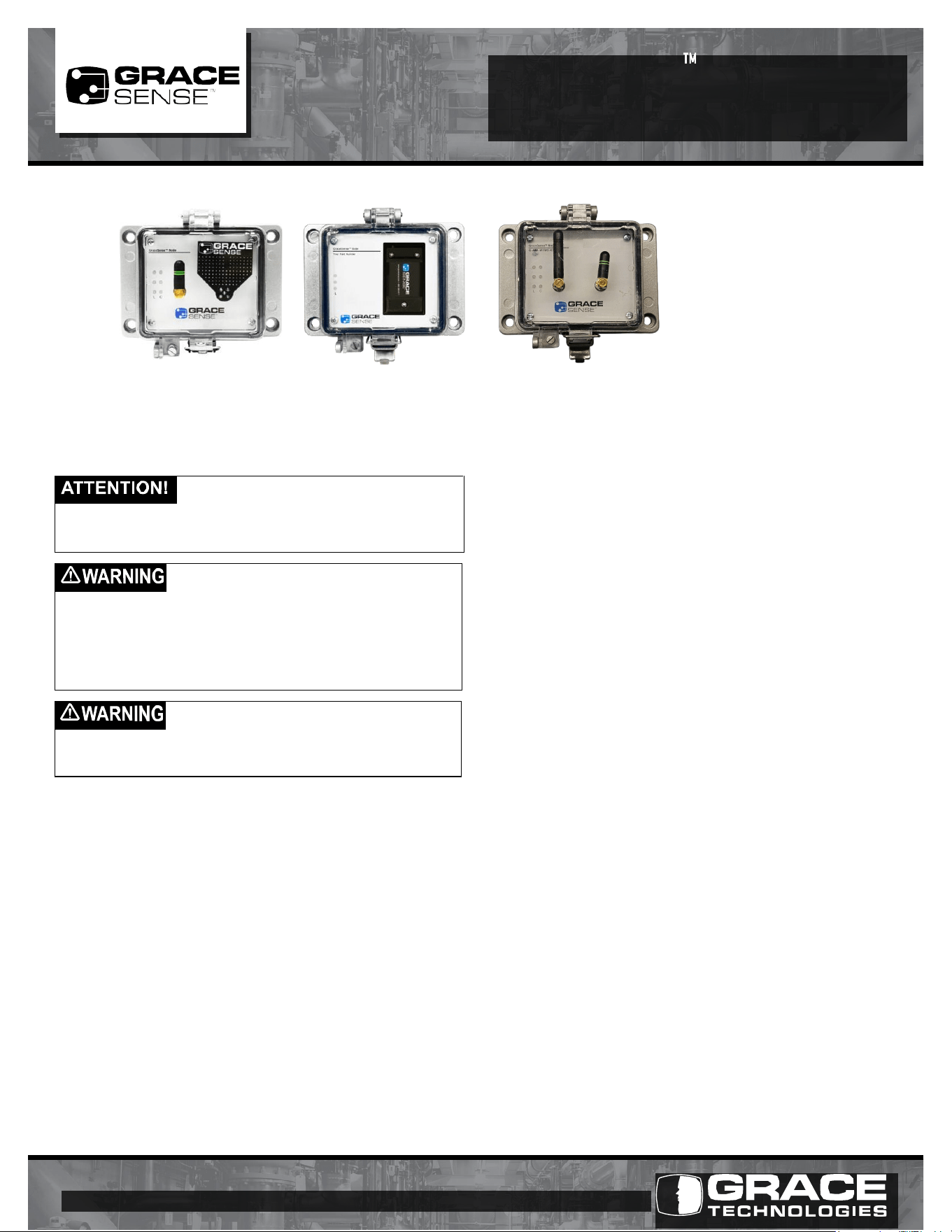
Actual product appearance may differ based on your unique configuration.
This instruction sheet provides important information regarding
installation of GraceSense™ Panel-Mount Nodes, CloudGates
™
ControlGates
™
. Please read these instructions in their entirety, and
follow all safety instructions before attempting installation.
The Panel-Mount Node
™
should be installed by
technically qualified personnel. Failure to install the
node in accordance with applicable codes and regulations and according to the
manufacturer’s specified guidelines may result in electrical shock, fire hazard,
poor performance or equipment failure, and may also void the product warranty.
Warning: Only qualified persons who are familiar with the
equipment being serviced and those who have received
proper safety training related to the hazards of the equipment should attempt to
install these sensors. The individual must also possess proper tools, training, and
be capable of repair or modification of the related equipment and its accessories.
Installation should conform to appropriate codes and standards. Failure to follow
these instructions may result in serious personal injury, death and/or property
damage. Always follow your facility’s PPE requirements when performing the
installation and maintenance tasks on your equipment.
Electrical Hazard Warning: The Panel-Mount Node/
CloudGate installation require wired connections inside
your equipment panel. Do not attempt to install these nodes while the equipment
is energized. Disconnect, lockout and tagout the input power source to your
panel/equipment before installing or servicing these nodes.
OVERVIEW
The GraceSense
™
Node/CloudGate is an environmentally rated
assembly mounted on the door of an enclosure. This assembly
can be used in conjunction with our GraceSense™ Vibration
& Temperature Node and Hot Spot Monitor or stand-alone.
The Panel-Mount Node
™
, CloudGate
™
, and ControlGates
™
may
consist of several transducer and sensor inputs, radios, power,
and integration options based on the preselected configuration.
GraceSense
™
Panel-Mount
™
Nodes are configurable to meet
the needs of your application. You may have a Node that takes
in hardwired sensor inputs, a CloudGate
™
(Node with cloud
connection), a ControlGate
™
(Node with control integration), or
a combination of these capabilities. The specific type you have
can be determined by the part number, communication interfaces/
radios, or application interfaces. Reach out to Grace at
[email protected] for more information on the capabilities of
our specific model.
BATTERY ASSEMBLY INSTRUCTIONS
(Applicable only if ordered with a battery)
1. Locate the battery supplied with the node.
2. Position the new battery on the node by aligning the 6-pin
connector and mounting screws of the battery to match the
corresponding locations on the node.
3. Insert all three battery mounting screws by turning clockwise
until threads start to engage.
4. Use a 6 -lobe T15 driver to tighten battery screws up to, but not
exceeding the torque value of 2.5 in. lbs.
5. To replace battery, refer to the battery replacement instructions
shipped with the new battery
Note: Do not attempt to disassemble GraceSense™ Node other
than the external mounted battery. There are no user-serviceable
components inside the node and battery assembly. Tampering
with the product may void the warranty.
INSTALLATION
All installations are intended to be mounted in or on an enclosure.
Installation should be performed by a qualified technician and
adhere to applicable regulatory codes. These devices are intended
to be mounted on the flat surface of enclosures having the same
type environmental ratings. Note: Each Zigbee radio has a range of
30m radius line-of-sight.
Antenna Positioning
As a general rule, the antenna(s) should be positioned vertically
(as shown in the images above). During installation, positioning the
Node upright with the antennas oriented vertically will provide the
best reception.
Power Source
The GraceSense™ Node requires power via 5V, USB Mini B,
24V DC, or 120V AC with power adapter (sold separately). When
used with a battery pack, the node can be self-powered or the
battery pack is used as a backup when the primary power is not
available. (Continued on back)
Warning: Verify an electrical conductor has been de-energized using an adequately rated test instrument before working on it. Follow appropriate Energy Control
(Lockout/Tagout) procedures as per OSHA Subpart S. © Grace Technologies, Inc. All rights reserved. Specifications are subject to change with/without notice.
GS-PMCG-IG-EN 2004
1515 East Kimberly Road • Davenport, IA • www.graceport.com • 1.800.280.9517
PANEL-MOUNT
NODE
INSTALLATION GUIDE
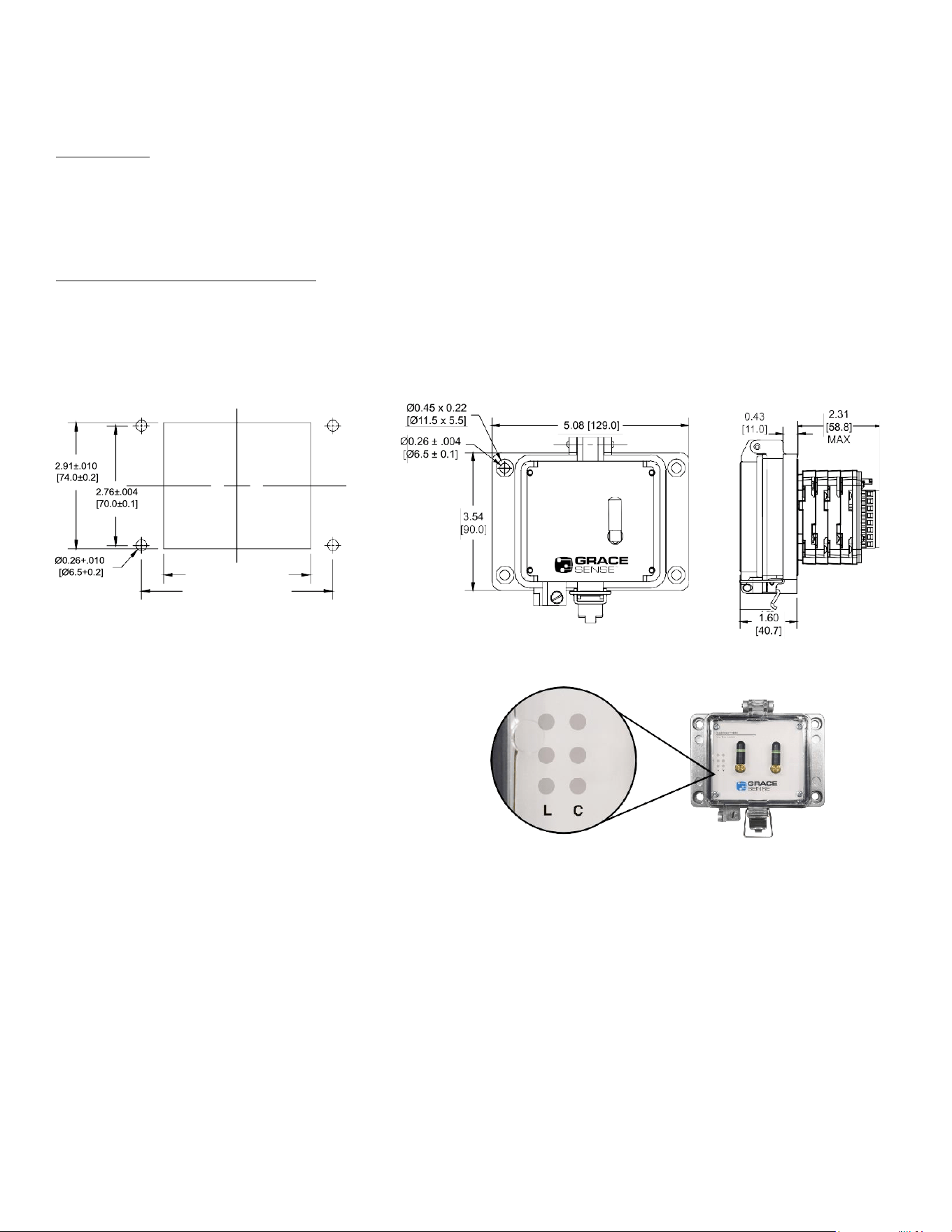
2.31
58.8
1.60
[40.7]
5.08 [129.0]
Ø0.45 x 0.22
[Ø11.5 x 5.5]
Ø0.26±.004
[Ø6.5±0.1]
3.54
[90.0]
Once installed, interface connections will be made from within the
panel enclosure.
Note: De-energize the equipment, and follow your facility’s
Lockout/Tagout procedures before attempting to make
connections to the node inside your panel/enclosure.
All installations:
1) Cut panel opening and mount housing assembly to enclosure
with supplied gasket. (Refer to the below dimensions for panel
cut-out details).
2) Connect low voltage interface wiring according to
documentation provided with the unit.
On units configured for optional AC power:
1) Connect outlet device as per code.
Note: It is the responsibility of the installer to ensure adequate
separation of high and low voltage circuits in the end-use product.
MECHANICAL SPECIFICATIONS
Housing: Cast aluminum base
Latch: Type 304 Stainless Steel
Cover: Polycarbonate, UV rated, V-O Flame rated
Insert Material: Acrylic UL94HB
QUESTIONS
For questions or technical support, please contact us at
1-800-280-9517.
PANEL CUTOUT OVERALL DIMENSIONS
LED INDICATION CHART
Upon installation, please refer to GraceSense™ LED
Indication Guide for determining what the LED indications
mean.
Once the installation is complete, log into
hub.gracesense.com to complete the set up.
GS-PMCG-IG-EN 2004
3.39±.010 [86.0±0.2]
4.41±.004 [112.0±0.1]

CERTIFICATIONS
Certifications only Apply to ComboGate SKUs:
• G-EIP-W1C1-K3XX
• G-EIP-W1C2-K3XX
• G-EIP-W1C3-K3XX
• G-EIP-W1C4-K3XX
• G-MIP-W1C1-K3XX
• G-MIP-W1C2-K3XX
• G-MIP-W1C3-K3XX
• G-MIP-W1C4-K3XX
• G-EIP-W1W2-K3XX
• G-MIP-W1W2-K3XX
FCC ID: 2BE57GWV1
IC: 32885-GWV1
PMN: ComboGate
HVIN: Z-100-IOT-ZBR
FVIN: GraceSense GatewayOS
This device complies with Part 15 of the FCC Rules and with License-exempt RSS standards of Industry Canada.
Operation is subject to the following two conditions: (1) This device may not cause harmful interference, and (2) This device must accept any interference
received, including interference that may cause undesired operation.
Exposure to radio frequency energy. The radiated output power of this device meets the limits of FCC/ISED Canada radio frequency exposure limits. This
device should be operated with a minimum separation distance of 20 cm (8 inches) between the equipment and a person’s body.
WARNING: Changes or modifications not expressively approved by the party responsible for compliance could void the user's authority to operate the
equipment. The term “IC:” before the radio certification number only signifies that Industry Canada technical specifications were met.
This radio transmitter [IC: 32885-GWV1] has been approved by Innovation, Science and Economic Development Canada to operate with the antenna type(s)
listed below, with the maximum permissible gain indicated. Antenna types not included in this list that have a gain greater than the maximum gain indicated
for any type listed are strictly prohibited for use with this device.
External Antennas:
Taoglas Part: GW26.0112 Gain: 1.8dBi Impedance: 50Ω
Le présent appareil est conforme aux CNR d'Industrie Canada applicables aux appareils radio exempts de licence. L'exploitation est autorisée aux deux
conditions suivantes: (1)l'appareil ne doit pas produire de brouillage, et (2)l'utilisateur de l'appareil doit accepter tout brouillage radioélectrique subi, même si
le brouillage est susceptible d'en compromettre le fonctionnement.
L’exposition à l’énergie radiofréquence. La puissance de sortie rayonné de cet appareil est conforme aux limites de la FCC/ISDE Canada limites
d’exposition aux fréquences radio. Cet appareil doit être utilisé avec une distance minimale de séparation de 20 cm entre l’appareil et le corps d’une
personne.
AVERTISSEMENT: Tout changement ou modification non expressément approuvé par le responsable de la conformité pourrait annuler le droit de l'utilisateur
à utiliser l'équipement. La mention “IC” devant le numéro de certification radio signifie uniquement que les spécifications techniques d'Industrie Canada ont
été respectées.
Cet émetteur radio [IC : 32885-GWV1] a été approuvé par Innovation, Sciences et Développement économique Canada pour fonctionner avec les types
d'antennes énumérés ci-dessous, avec le gain maximal autorisé indiqué. Les types d'antennes non inclus dans cette liste et dont le gain est supérieur au
gain maximal indiqué pour l'un des types énumérés sont strictement interdits avec cet appareil.
Antennes externes:
Taoglas Part: GW26.0112 Gain: 1.8dBi Impedance: 50Ω
GP-PMCG-IG-EN 2004