
Operang Instrucons for the
Planar
S u b-Ba ss
System
Cauon Marking Explanaon
The lightning ash with arrowhead symbol within an equilateral triangle is intended to alert the
user to the presence of un-insulated dangerous voltage within the product’s enclosure that may
be of sucient magnitude to constute a risk of electric shock to persons.
The exclamaon point within an equilateral triangle is intended to alert the user to the presence
of important operang and maintenance (servicing) instrucons in the literature accompanying
the appliance.
1

32
1 Read all of these instrucons.
2 Save these instrucons for future use.
3 Heed all warnings.
4 Follow all instrucons.
5 Do not use this apparatus near water.
6 Clean only with automove polish and micro ber cloth.
7 Install in accordance with the manufacturer’s instrucons.
8 Do not install near any heat sources such as radiators, heat registers, stoves or other apparatus (including
ampliers) that produce heat.
9 Do not defeat the safety purpose of the grounding-type plug. A grounding type plug has two blades and
a third grounding prong. The third prong is provided for your safety. If the provided plug does not t into
your outlet, consult and electrician for replacement of the obsolete outlet.
10 Protect the power cord from being walked on or pinched parcularly at plugs, convenience receptacles,
and the point where they exit from the apparatus.
11 Only use aachments/accessories specied by the manufacturer.
12 Use only with a cart, stand, tripod, bracket, or table specied by the manufacturer, or sold with the apparatus.
When a cart is used, use cauon when moving the cart/apparatus combinaon to avoid injury from p-over.
13 Unplug this apparatus during lightning storms or when unused for long periods of me.
14 Refer all servicing to qualied service personnel. Servicing is required when the apparatus has been damaged
in any way, such as power-supply cord or plug is damaged, liquid has been spilled or objects have fallen
into the apparatus, the apparatus has been exposed to rail or moisture, does not operate normally, or
has been dropped.
15 Minimum distances 10cm around the apparatus for sucient venlaon.
Important Safety Instrucons

16 The venlaon should not be impeded by covering the venlaon openings with items, such as newspapers,
table-cloths, curtains, etc.
17 No naked ame sources, such as lighted candles, should be placed on the apparatus.
18 Aenon should be drawn to the environmental aspects of baery disposal.
19 The use of apparatus in moderate climates.
20 Baeries shall not be exposed to excessive heat such as sunshine, re or the like.
Cauon: Any changes or modicaons not expressly approved by the party responsible for compliance
could void the user’s authority to operate this equipment.
Warning
To reduce the risk of re or electric shock, do not expose this apparatus to rain or moisture.
The apparatus shall not be exposed to dripping or splashing and no objects lled with liquids, such as vases,
shall be placed on apparatus.
The mains plus is used as disconnect device. The mains plug of the apparatus should not be obstructed OR
should be easily accessed during intended use. To be completely disconnected from the power input, the
mains plug of the apparatus shall me disconnected from the mains.
An appliance with a protecve earth terminal should be connected to a mains outlet with a protecve
earth connecon.
Design Safety
These apparatus are supplied with a detachable mains cord. For 230V operaon an 4A fuse is ed in
the socket of the Planar PL-2 and a 2.5A fuse is ed in the socket of the Planar PL-1, for 120V operaon
a 8A fuse is ed for the Planar PL-2 and a 5A fuse is ed for the Planar PL-1. Should the fuse need to be
replaced use a similar rated fuse approved to ASTA or BSI 362 standards. Do not use without the fuse cover
in place. Replacement fuse covers are available from your distributor.
3
5
4
Aenon Explicaon Marquage
L’éclair avec le symbole de pointe de èche dans un triangle équilatéral est desné à alerter
l’ ulisateur de la présence de non isolée tension dangereuse à l’intérieur de l’enceinte du
produit qui peut être d’une ampleur susante pour constuer un risque d’électrocuon pour
les personnes.
Le point d’exclamaon dans un triangle équilatéral est desné à alerter l’ulisateur de la
présence d’instrucons dans la documentaon accompagnant l’appareil exploitaon et de
maintenance (entreen).

5
1 Lisez aenvement ces instrucons.
2 Conservez ces instrucons.
3 Respectez tous les averssements.
4 Suivez toutes les instrucons.
5 Ne pas uliser cet appareil près de l’eau.
6 Neoyez seulement avec du vernis automobile et ssu microbre.
7 Installer conformément aux instrucons du fabricant.
8 Ne pas installer près de sources de chaleur telles que des radiateurs, registres de chaleur, poêles ou autres
appareils (y compris les amplicateurs) qui produisent de la chaleur.
9 Ne pas contourner le disposif de sécurité de la prise de terre. Une che de terre a deux lames et une
troisième broche de mise à la terre. La troisième broche est fournie pour votre sécurité. Si la che fournie
ne rentre pas dans votre prise, consultez un électricien pour le remplacement de la prise obsolète.
10 Protégez le cordon d’alimentaon ne soit piéné ou pincé, en parculier au niveau des ches, des prises
de courant, et le point de sore de l’appareil.
11 Ulisez uniquement des xaons / accessoires spéciés par le fabricant.
12 Ulisez seulement avec un chariot, stand, trépied, support ou table spécié par le fabricant, ou vendu
avec l’appareil. Lorsque vous ulisez un chariot, soyez prudent lorsque vous déplacez l’ensemble chariot /
appareil pour éviter les blessures en cas de chute.
13 Débranchez cet appareil pendant un orage ou lorsqu’il est inulisé storsm pour de longues périodes de temps.
14 Conez toute réparaon à un personnel qualié. Une réparaon est nécessaire lorsque l’appareil a été
endommagé de quelque façon que ce cordon d’alimentaon ou la che est endommagé, du liquide a
été renversé ou des objets sont tombés dans l’appareil, l’appareil a été exposé à rail ou à l’humidité, ne
fonconne pas normalement, ou a été échappé.
Informaons Importantes Relaves a la Securite
4

15 10cm distance minimale autour de l’appareil pour une aéraon susante.
16 Il convient que l’aéraon ne soit pas gênée par l’obstrucon des ouvertures d’aéraon par des objets tels
que journaux, nappes, rideaux, etc.
17 Il convient de ne pas placer sur l’appareil de sources de ammes nues, telles que des bougies allumées.
18 Il convient d’arer l’aenon sur les problèmes d’environnement dus à la mise au déchet des piles.
19 Si l’appareil est desné à être ulisé sous un climat tempéré.
20 Les baeries ne doivent pas être exposées à une chaleur excessive telle que celle du soleil, d’un feu ou d’origine.
Averssement
Cet arcle est lourd. Pour éviter tout risque de blessure, prendre soin lors de la manipulaon.
L’ appareil ne doit pas être exposé à des éclaboussures et aucun objet rempli de liquide, comme des vases,
ne doit être placé sur l’appareil.
Les conduites Plus est ulisé comme disposif de déconnexion. La che de l’appareil ne doit pas être
obstruée OU doit être facilement accessible pendant l’ulisaon. Pour être complètement déconnecté de
l’alimentaon électrique, le cordon d’alimentaon de l’appareil doit me débranché.
Un appareil avec une borne de terre doit être branché sur une prise de courant en étant relié à la terre.
Aenon: Tout changement ou modicaon non expressément approuvés par la pare responsable de la
conformité pourraient annuler l’autorité de l’ulisateur à uliser cet équipement.
Sécurité Design
Ces appareils sont fournis avec un cordon secteur détachable. Pour le fonconnement en 230V, un fusible
de 4A est installé dans la prise du Planar PL-2 et un fusible de 2.5A dans la prise du Planar PL-1, pour un
fonconnement en 120V, un fusible de 8A est installé pour le Planar PL-2 et un fusible de 5A pour le Planar
PL-1. Si le fusible doit être remplacé, ulisez un fusible de même calibre approuvé selon les normes ASTA ou
BSI 362. Ne pas uliser sans le couvercle de fusible en place. Des couvre-fusibles de rechange sont
disponibles chez votre distributeur.
6

7
This device complies with Part 15 of the FCC Rules. Operaon is subject to the following two condions:
1 This device may not cause harmful interference, and
2 This device must accept any interference received, including interference that may cause undesired operaon.
NOTE: This equipment has been tested and found to comply with the limits for a Class B digital Device,
pursuant to Part 15 of the FCC Rules. These limits are designed to provide reasonable protecon against
harmful interference in a residenal installaon.
This equipment generates, uses and can radiate radio frequency energy and, if not installed and used in
accordance with the instrucons, may cause harmful interference to radio communicaons. However,
there is no guarantee that the interference will not occur in a parcular installaon. If this equipment
does cause harmful interference to radio or television recepon, which can be determined by turning the
equipment o and on, the user is encouraged to try and correct the interference by one or more of the
following measures:
Reorient or relocate the receiving antenna.
Increase the separaon between the equipment and receiver.
Connect the equipment into an outlet on a circuit dierent from that to which the receiver is connected.
Consult the dealer or an experienced radio/TV technician for help.
IMPORTANT: When Planar is not mounted to a wall, it may p if subjected to force, impact, or climbing.
This includes use on the accessory stand or any other freestanding placement.
To reduce the risk of p-over, an an-p restraint system is included. REL strongly recommends installing
this restraint in all freestanding applicaons.
Failure to install the restraint may result in injury or damage.
FCC STATEMENT

8
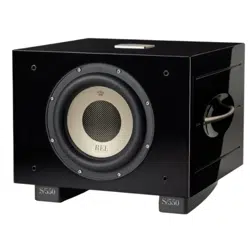
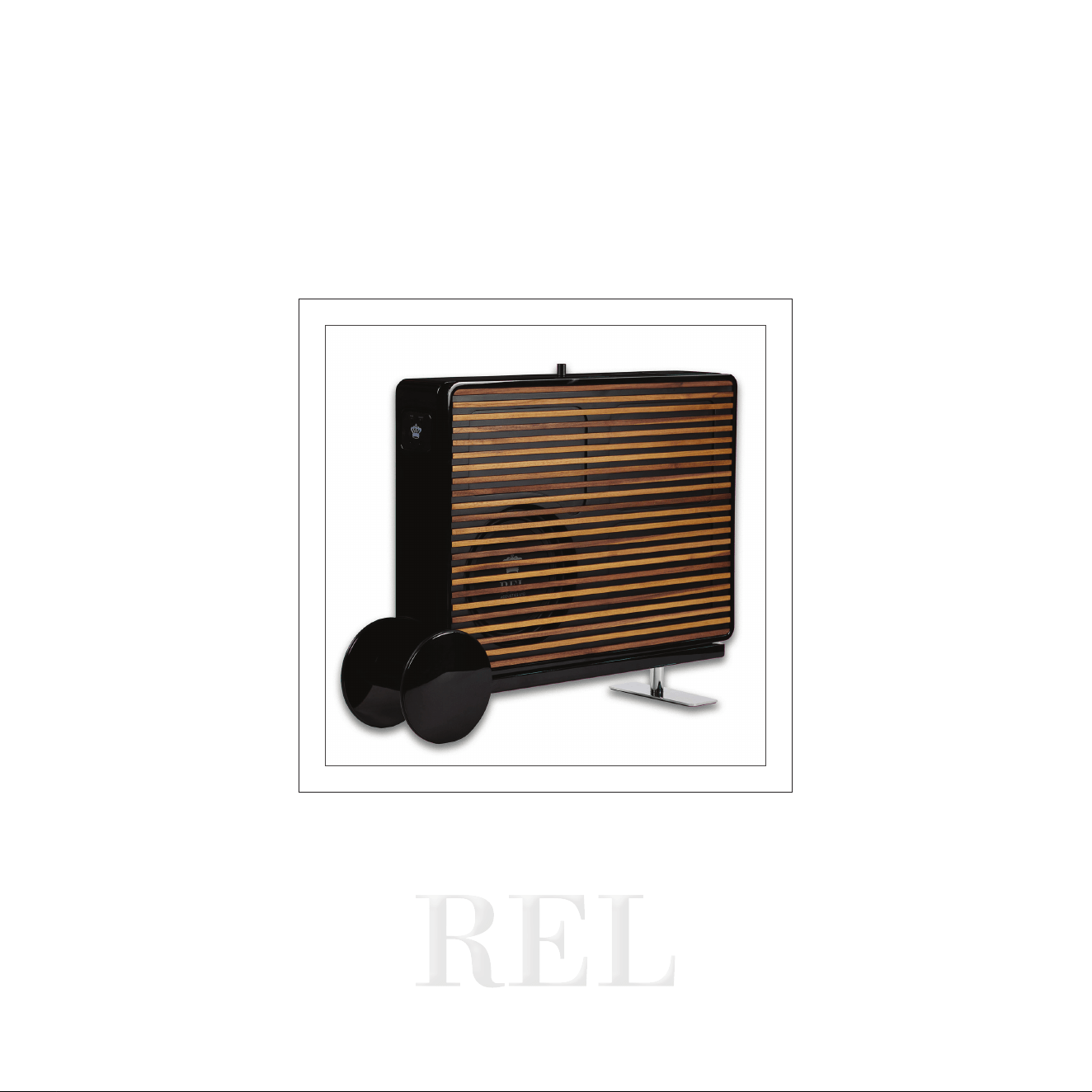
Congratulaons on your purchase of your new Planar thin-panel boundary eect subwoofer.
Planar is unlike convenonal subwoofers. While most subwoofers are designed to bale room acouscs
from somewhere out in the room, Planar is designed to work with the room itself by operang in close
relaonship with the wall behind it. REL refers to this as boundary eect coupling.
By placing Planar close to the wall, or mounng it using the included hardware, the wall itself becomes part
of the acousc system. This allows Planar to produce deep, powerful bass and remarkable scale from an
enclosure only 4.5 in. (130 mm) thick.
Tradional subwoofers oen require large cabinets placed well out into the room in order to achieve deep
bass and high output. With Planar, we asked a dierent queson: what if a subwoofer could remain close to
the wall while sll delivering the scale, dynamics, and depth expected from a REL?
The answer is Planar.
Its thin form allows for placement opons that are simply not possible with many tradional subwoofers
while also helping preserve the openness and usability of the living space. Whether mounted directly to
the wall or posioned close to the wall using Planar Cart, Planar is designed to make intelligent use of the
surrounding environment to deliver deep, natural bass with minimal intrusion into the room.
Planar was developed for far more than a single type of system or environment. Whether used with
tradional stereo speakers, architectural in-wall or in-ceiling systems, open oor plan living spaces, or
advanced home theatre installaons, the same core principles of placement, integraon, and tuning apply.
Throughout this manual, we will guide you through how those principles can be adapted for dierent
applicaons so your Planar performs naturally and seamlessly within your system.
Welcome to the REL Family
9
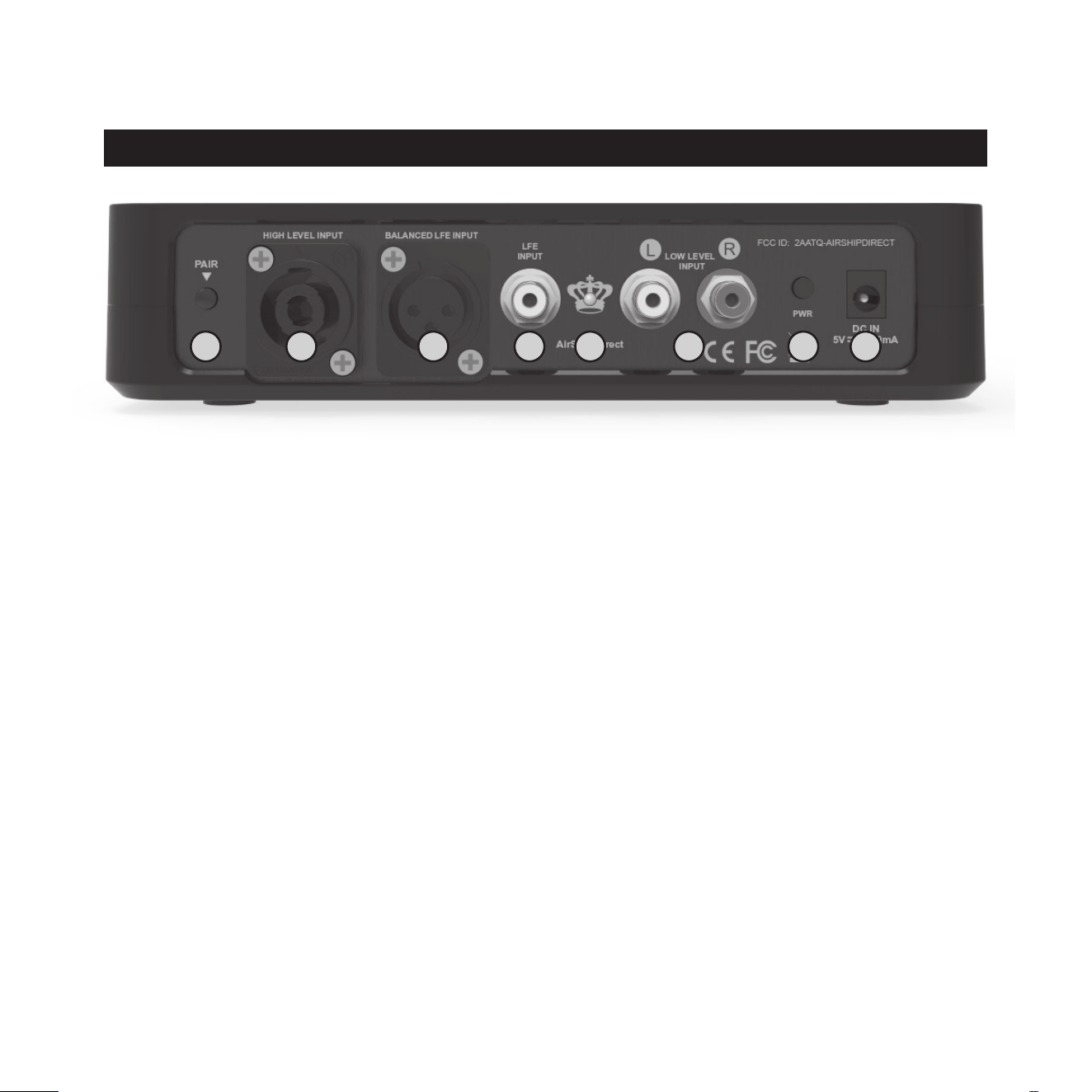
REL AirShip Direct™ Transmier
1 PAIR Buon: Used to pair REL AirShip Direct™ transmier with receiver.
2 HIGH-LEVEL INPUT (Neutrik® SpeakOn® Socket): Use to connect HIGH-LEVEL to the main front
amplier speaker terminals.
3 BALANCED LFE INPUT (XLR): Used to connect to the balanced .1/LFE output from a home theatre processor
with XLR cables.
4 LFE INPUT (RCA): Used to connect to the .1/LFE output from a home theatre processor. Should be used
in conjuncon with REL HIGH-LEVEL connecon for the ulmate theatre experience.
5 PAIR LED: Indicates whether the REL AirShip Direct™ transmier is paired with the receiver or not.
6 LOW-LEVEL INPUT (RCA): Used to connect to a stereo output from a stereo pre-amp or home
theatre processor.
7 PWR Power Switch: Used to turn on and o REL AirShip Direct™ transmier.
8 DC IN Power Adapter Socket: DC input socket that accepts a detachable power adapter.
REL Planar Panel Connecon Legend
8
2 3
1 5 6
7
4
10
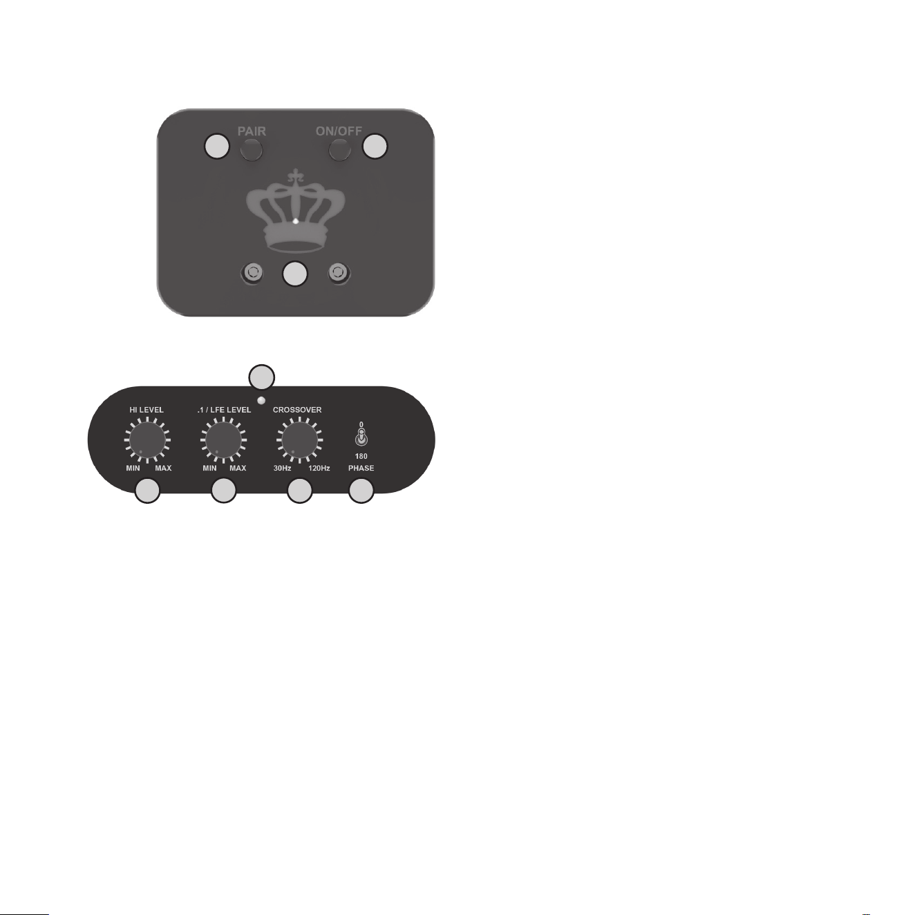
REL AirShip Direct™ Receiver
1 PAIR Buon: Used to pair REL AirShip Direct™
receiver with transmier.
2 ON/OFF Power Switch: Used to turn on and o
REL AirShip Direct™ reciever.
3 LED: Indicates whether the REL AirShip Direct™
receiver is paired with the transmier or not.
REL Planar Control Panel
1 HI LEVEL Volume Control: Use to adjust
output when using either HIGH-LEVEL or
LOW-LEVEL input. Do not use both inputs
simultaneously.
2 .1/LFE LEVEL Volume Control: Use to adjust
output level when using .1/LFE input from a 5.1
amplier or processor.
3 LED Power indicator: Illuminates white when
on, red when in Standby Mode.
4 CROSSOVER Control: Used to select crossover
frequency. Variable between 30 Hz and 120 Hz.
5 PHASE Switch: Used to set phase 0-180 degrees.
2
1
3
2
3
1 54
11
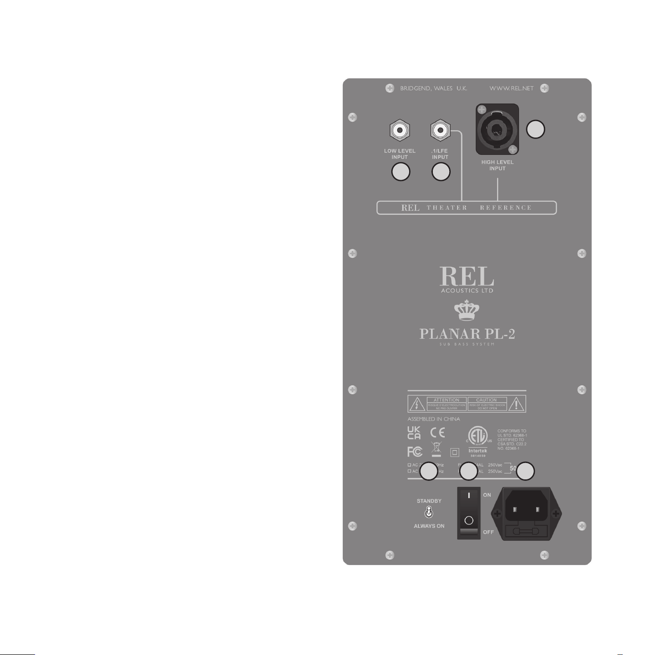
REL Planar Back Panel
1 LOW LEVEL INPUT: Used to connect LOW-LEVEL
to the output of a preamplier, integrated
amplier or receiver ONLY when HIGH-LEVEL
INPUT cannot be properly connected. (For home
cinema, use.1/LFE INPUT).
2 .1/LFE INPUT: Used to connect to the .1/LFE
output from a 5.1 amplier of processor. Should
be used in conjuncon with REL HIGH-LEVEL
connecon for the ulmate theatre experience.
3 HIGH LEVEL INPUT (Neutrik SpeakOn Socket):
Use to connect HIGH-LEVEL to the main front
amplier speaker terminals.
4 STANDBY / ALWAYS ON switch: Use to set
Standby or Always On Mode.
5 ON / OFF Power Switch: Use to turn unit on or o.
6 IEC Mains Socket: Fused mains (AC) input socket
that accepts a detachable power cord.
2
3
1
54 6

12
Connecng To Your System
The receiver will come mounted to the side panel of the Planar Sub-Bass System using supplied hardware.
In the case that you need to swap a receiver the following informaon is provided.
Please turn the REL o and make sure that the ON/OFF switch is in the o posion before mounng the
receiver. Make sure the electrical interface is fully engaged to ensure proper performance and the mounng
screws need only be nger ght.
Your Planar PL-1 or Pl-2 comes with a REL AirShip Direct™ transmier that is supplied with each of these
subwoofers. Both the Planar subwoofer cabinet and the AirShip Direct™ transmier will require AC power
from a wall plug. There is an AC cable supplied for the subwoofer cabinet and a power adapter cable supplied
for the transmier. The intent here is to nd the perfect place for the Planar on a wall with the AirShip
Direct™ transmier located remotely without long cables being needed to deliver the deep bass your Planar
is capable of. Simple, seamless, and easy.
Always switch your system o before disconnecng any wires.

13
To increase the versality of connecon, the Planar models have three separate and disnct types of inputs,
although only two will be used as one must decide between HIGH-LEVEL INPUT or a LOW-LEVEL INPUT. They are:
1 HIGH-LEVEL INPUT connecon which uses a Neutrik SpeakOn terminal.
2 .1/LFE INPUT consisng of your choice of RCA or XLR connectors.
3 LOW-LEVEL stereo or mono (if using stereo pairs of RELs) inputs. These include RCA connecons for stereo
input, although if using stereo pairs or Line Arrays of RELs only one input per channel need be used. This
is to facilitate use with both two-channel stereo systems as well as AV surround sound systems.
The HIGH-LEVEL, unbalanced, dual-channel (stereo) input is via a Neutrik SpeakOn connector and is
designed to accept the stereo (two-channel) signals from the speaker terminals of your receiver, integrated
amplier or basic amplier. This has the advantage of ensuring that your subwoofer receives precisely the
same signal as the main speakers, which means that the character of the bass from the main system is
carried forward into the Sub-Bass System.
This is a very important point which, when combined with REL’s Naturalsound™ input lters, ensures far
superior system integraon of your REL Sub-Bass System with the main system.
URGENT NOTE: Plugging in the REL HIGH-LEVEL CABLE. Prior to doing so please STOP and carefully examine
the end of the cable’s connector. Idenfy the keyway on the end of the plug and take care to align the
keyway with the matching slot on the rear panel SpeakOn HIGH-LEVEL INPUT. To engage the Neutrik
SpeakOn plug, insert it carefully into the SpeakOn terminal on the rear panel of your REL and rotate it
clockwise unl it clicks. If any noceable resistance is encountered, please stop, reexamine the orientaon
of the cable’s plug to the SpeakOn terminal on your new REL and take care to match the keyway and slot
before damage occurs.
How to Properly Detach the REL High-LEVEL CABLE from the REL Sub-Bass System: To remove the Neutrik
SpeakOn plug, rmly grip the body of the plug, placing thumb on serrated chrome lever. Slide lever
rearward while rotang plug counterclockwise 1/4 turn and withdraw.
XLR and RCA connecons are provided for input from the .1/LFE channel of a home cinema processor.
HIGH-LEVEL and .1/LFE inputs can and should be used simultaneously in Theatre Applicaons. The benets
are two-fold when used with a home cinema processor set to Full Range or as low as your processor or
receiver will permit. The .1/LFE INPUT reproduces the .1/LFE channel, and the HIGH-LEVEL connecon

14
underpins the main front speakers. The main front speakers should be set to the ‘large’ or full range if
available opon on the AV processor. See “REL Theater Reference™ Home Cinema Applicaons” for more
informaon (page 18).
There are two RCA sockets for LOW-LEVEL le and right channel connecon to the output of a stereo
preamplier or receiver. These may be used in cases where HIGH-LEVEL INPUT is not an opon.
We have designed the Planar with connecons on the back of the cabinet for users that wish to connect
audio using wiring. Should you need to pursue this path, please do NOT aempt to connect using the
wireless transmier as well. It is possible to damage your REL by overdiving the inputs using both of these
opons. These inputs are simplied to a Neutrik SpeakOn for HIGH-LEVEL INPUT, a phono socket for
LOW-LEVEL INPUT and a single phono socket for .1/LFE INPUT.
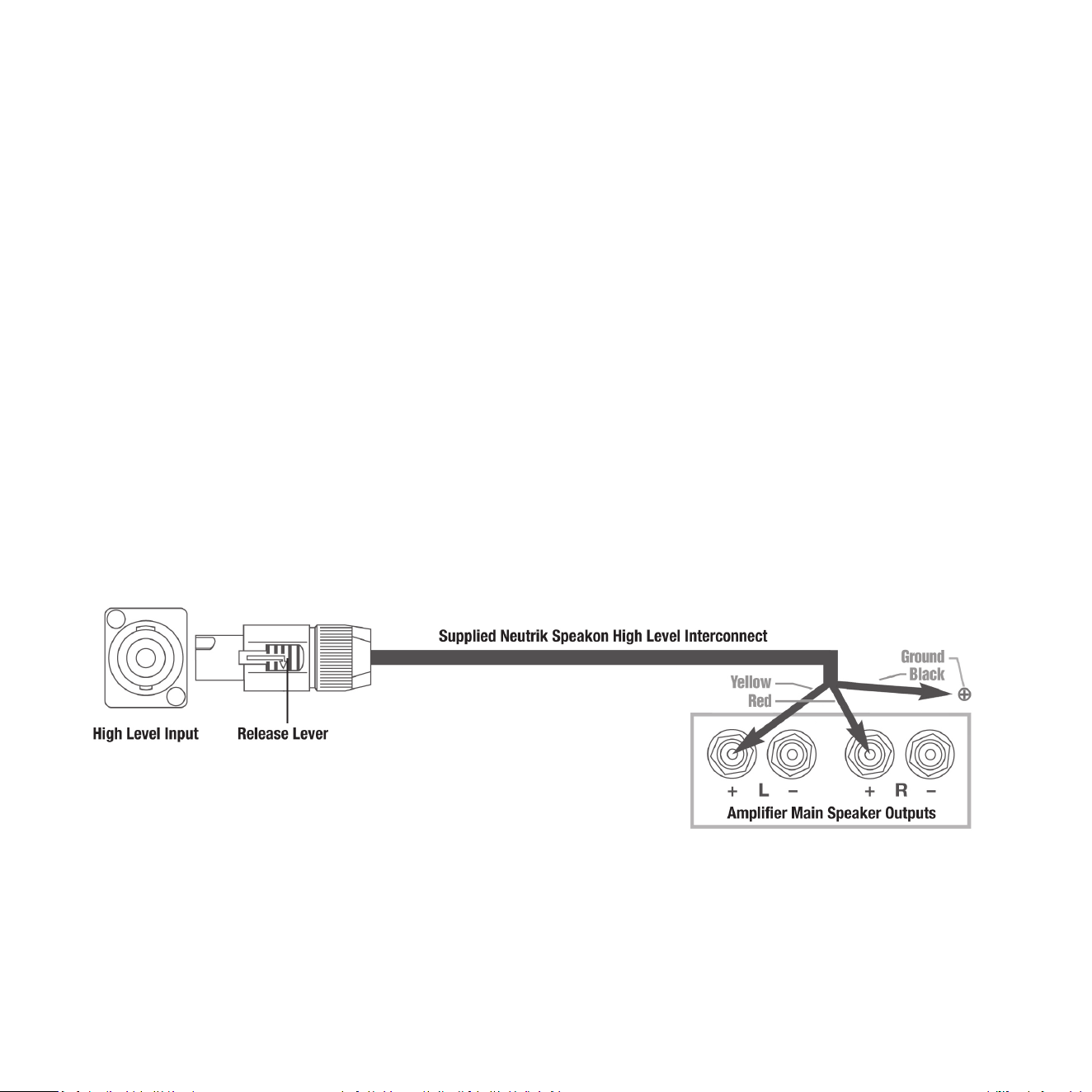
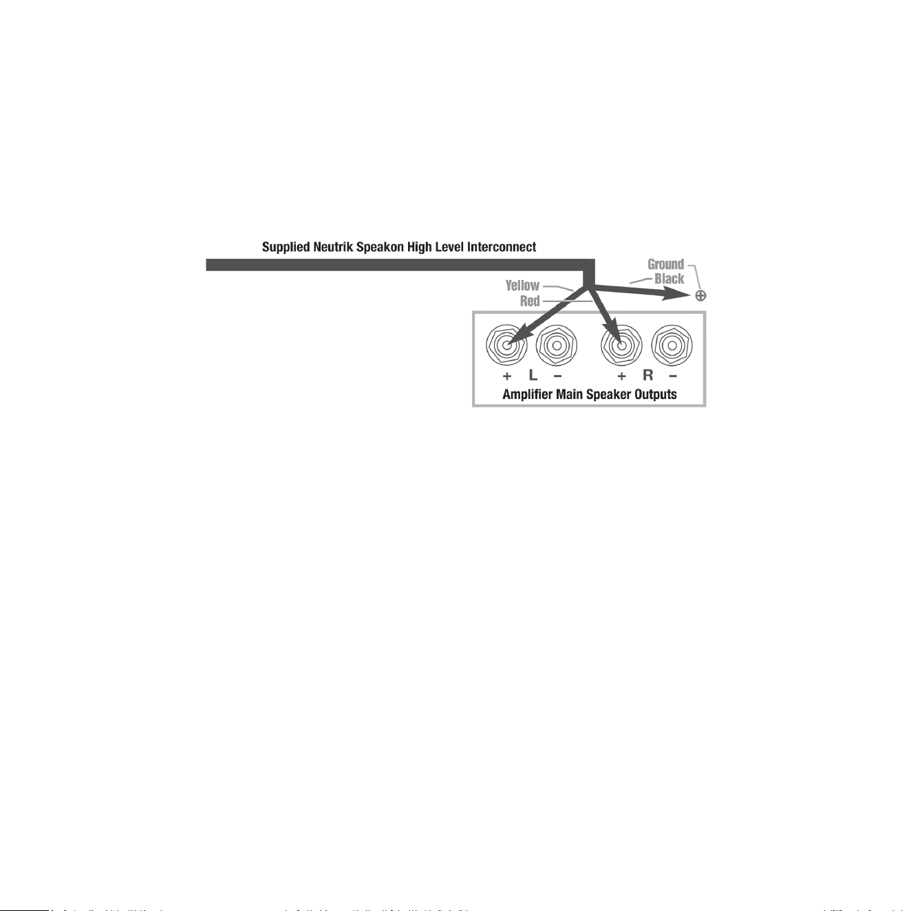
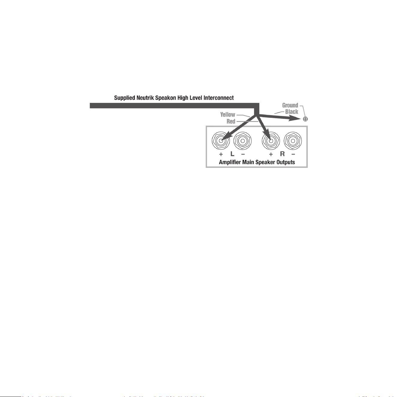
HIGH-LEVEL INPUT: Connecons should be made to the same binding post on main amplier as the main
speakers. Red to amplier main right speaker red terminal, yellow to amplier main le speaker red terminal
and black to a signal or chassis ground of the amplier. Plug the Neutrik SpeakOn plug into the HIGH-LEVEL
SpeakOn socket.
Note: This connecon does not draw current from the power amplier and, yes, your REL is a powered Sub-Bass
System. However, by deriving its signal from the main power amplier, beer sound quality is achieved.
.1/LFE INPUT: This requires a RCA to RCA or XLR to XLR cable and is a dedicated true .1 channel. This circuit
passes the .1/LFE signal through with only the required 120 Hz lter.
LOW-LEVEL INPUT: This stereo phono input allows for convenonal connecon from a preamplier and
should be used in the rare event that a HIGH-LEVEL connecon proves incompable. Plug one end of a
single phono-phono cable into the LOW-LEVEL INPUT jack of the REL and the other end into either the le
or right channel output of your preamplier. A second Planar may be purchased to fully integrate with your
stereo speakers if using low level out, as in acve loudspeakers.
These connecons can be made on the Planar through the REL AirShip Direct™ transmier. Using input
connecons to both the REL AirShip Direct™ transmier and direct to the Planar back panel are not permied.
PHASE SWITCH: Used to set phase
Posion 0 / HIGH-LEVEL, LOW-LEVEL or LFE: 0 degrees phase
Posion 180 / HIGH-LEVEL, LOW-LEVEL or LFE: 180 degrees phase
PHASE SELECTION AFFECTS BOTH HIGH-LEVEL AND LOW-LEVEL INPUTS
CROSSOVER is always engaged for HIGH-LEVEL INPUT. The .1/LFE signal does not pass through the crossover circuit.
15
Making Connecons
It is helpful to know that you will almost always connect the REL to the input on the rear panel labeled
HIGH-LEVEL INPUT. This connecon is made to the REL AirShip Direct™ transmier using the supplied 4.9’
(1.5 meter) cable, the bare leads of which connect to the speaker output terminals of the power amplier.
The easy and foolproof connecon at the REL is done with a Neutrik SpeakOn connector. The purpose of
connecng to the speaker output terminals is one of the unique secrets of REL’s success. By connecng to
the high-level input on the REL from the amplier, you build forward the sonic signature of your main system,
including the tonal balance and ming cues of the enre electronics chain. In this way, the REL is fed the
exact signal that is fed to the main speakers.
Connecng
HIGH-LEVEL connecon, using the enclosed cable with the Neutrik SpeakOn connector, is always the rst
choice. This connecon can be made without aecng the performance of the amplier because the REL’s
amplier input impedance is 150,000 ohms, in eect producing NO addional load on the rest of your system.
• The standard HIGH-LEVEL hook up procedure is aaching the red wire to the amplier’s right posive
speaker output terminal; aach the yellow wire to the amplier’s le posive speaker output terminal;
aach the black wire to whichever of the amplier’s chassis ground screws or bolts is convenient; plug
the SpeakOn connector into the Sub-Bass System’s HIGH-LEVEL INPUT.
16
• For dierenal (i.e. fully balanced) stereo ampliers using one REL, simply use the standard connecng
scheme of connecon to an exposed chassis ground screw or bolt. It may also be allowed to “oat” or
hang down without connecon to ANY terminal. Should hum occur using this method, please return to
connecng to chassis ground or an unused RCA connector on the rear of a preamp or amplier. Please
contact your dealer should there be any quesons concerning this or any other hookup procedure.
NOTE: The REL AirShip Direct™ transmier is equipped with internal circuitry to allow seamless connecon
to Class-D (digital) main ampliers. If connecng to a Class-D amplier, follow the above connecon
procedure for dierenal ampliers.
17
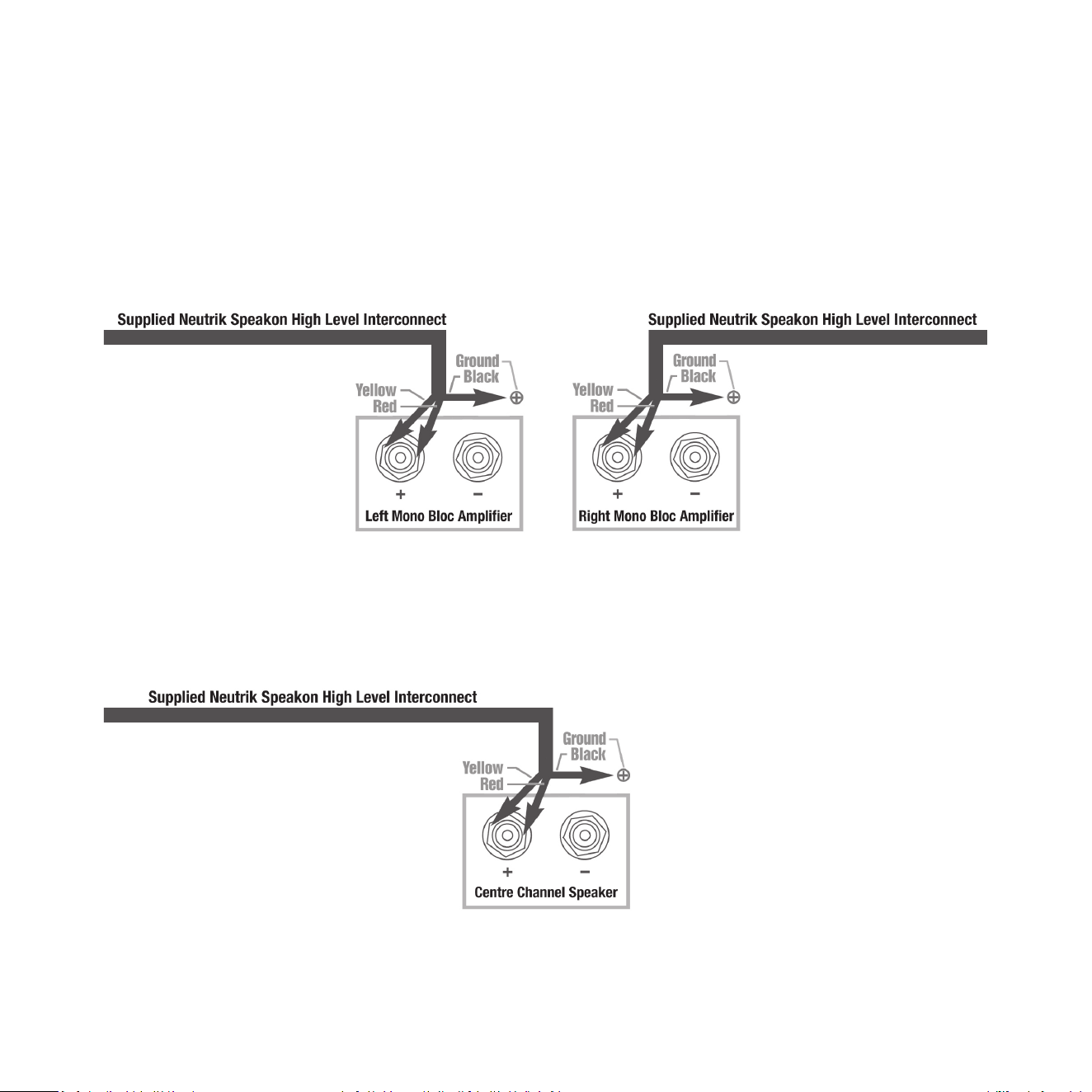
When connecng RELs to Mono Bloc ampliers (2) RELs, one for each amplier, must be used. Connect
the black wire of each REL to chassis ground screws or bolts of the corresponding amplier channel; twist
together the red and yellow wires of each REL separately and connect each pair to the posive speaker
terminal of the corresponding amplier channel. In some instances, this will result in exceponally high gain
(output) from the RELs. If it seems simply too high in gain, please remove either the red or yellow wire from
the twisted pair. This will reduce output by half and restore a natural dynamic.
If connecng a single REL as a dedicated centre channel sub, twist together the red and yellow wires and
connect these paired wires (red/yellow paired together) to the posive centre channel amplier terminal.
Connect the black wire to a ground lug or chassis screw on the amplier.
18
If connecng a REL as a dedicated rear channel sub, connect the yellow wire to the le rear posive speaker
terminal; connect the red wire to the right rear posive speaker terminal, connect the black wire to a
ground lug or chassis screw. If the amplier is of balanced dierenal design, please follow the instrucons
in the secon above labeled Dierenal Connecon.
LOW-LEVEL connecon (via RCA connectors) is always an opon if HIGH-LEVEL connecon is not possible.
When connecng to the low-level inputs in a system in which HIGH-LEVEL connecon is not possible, such
as if using internally amplied speakers, connect le and right RCA cables between the LOW-LEVEL INPUT
jacks of the REL and the le and right channel outputs of your preamplier.
When connecng to a home cinema system where a .1/LFE channel output is present, connect a single
phono or XLR cable between the sub output of the processor/receiver and the .1/LFE input jack on the
AirShip Direct™ wireless transmier.
REL Theatre Reference™ Home Cinema Applicaons
For home theatre systems, once the standard set-up for two-channel outlined above is complete, the LFE
output from the processor or receiver should be connected to the .1/LFE input and appropriate volume
adjustments made using the .1/LFE LEVEL control. For this conguraon, you must set the processor to the
“large” or “full range” seng for the le and right speakers in order for the REL to receive the bass signal via
the HIGH-LEVEL CABLE. In this conguraon, the REL provides support for both the le and right speakers
for two-channel listening, and support for the LFE when lms are playing. Most processors will allow you
to defeat the subwoofer output when listening in the two-channel mode. The eect of this set-up is one of
greatly increased dynamics in the mid-bass range, no bass bloat, and a greater degree of space and ming
from the special audio eects.

19
Now that the AirShip Direct™ wireless transmier is connected to your amplier (ideally using the
HIGH-LEVEL CABLE), unpack the Planar subwoofer and place on a clean sheet or towel to protect nish.
Each Planar comes pre-paired with its REL AirShip Direct™ transmier box. If the units need to be re-paired,
or you would like to add more Planar subs to the system, there are a few easy steps to follow.
REL Planar wireless Sub-Bass Systems come paired to a single transmier out of the box. In the event that
the sub and transmier becomes un-paired, the owner must follow the procedure below to repair.
1 Make sure that the transmier’s AC to DC wall plug supply is connected to an AC outlet, and that the
barrel connector is connected to the transmier. A white LED on the control panel of the transmier will
indicate the unit is on by blinking in the standby paern which is one ash per second.
2 Make sure that the sub is plugged into an AC outlet using the supplied AC cable and that the sub is turned
on. Power switch is located on the rear panel.
3 Exercise the momentary PAIR switch on the transmier located on its control face. This will make the
transmier look for a new sub. Note that the LED ash paern will change to two blinks per second.
4 Next exercise the momentary PAIR switch on the receiver located on the side panel.
5 At this point the sub and transmier should nd each other and pair together. This will be indicated by
the white LEDs on both the transmier and control panel staying constantly on (no ashing).
The REL Planar wireless sub bass system can pair up to four subwoofers using one transmier. To pair more
than one sub to a single transmier, follow the instrucons above and repeat for each subwoofer added.
Pairing
Status LED Indicator
Paired Connuously on
Searching Blinks twice per second
Standby Blinks once per second

21
When using two transmiers with two independent systems in proximity to each other (within the same house):
1 Follow the pairing instrucons above for the rst system.
2 Turn o the rst transmier.
3 Follow the pairing instrucons above for the second system.
4 Turn the transmier on for the rst system back on.
Each Planar will come out of the box independently paired to its own AirShip Direct™ transmier and will
not have issues with “cross talk.” However, if there is a problem, re-pairing each Planar for independent
operaon should eliminate cross talk.
20

21
Now that you have the AirShip Direct™ transmier box connected to your amplier and wirelessly paired to
Planar, it is me to choose a locaon and dial in Planar for your specic room. This secon will help guide you
in selecng the best locaon and choosing the basic sengs for Planar, but will not discuss installaon. The
installaon process will be discussed in detail in the next secon.
Before You Begin
1 Planar is unlike any other REL Sub-Bass System and therefore requires special consideraons for
placement. Planar is designed to be mounted on the wall and will take advantage of the enre wall
to help generate deep bass pressurizaon.
2 Planar can be mounted to masonry or sheetrock walls. For sheetrock walls, it is NECESSARY that Planar
is anchored/screwed into studs in order to properly support long term use. The specialized brackets
developed just for Planar require mounng BOTH upper and lower right side screws into a stud as well as
the upper bracket’s le side. The lower bracket comes supplied with an insert that must be GLUED and
screwed into the wall. If one chooses not to use glue, expect rales to develop.
3 Studs are structural members behind the surface of modern walls. There are generally two types of studs,
wood or metal (typically aluminum). Usually there is a sheet of pre-manufactured building material, oen
referred to as sheetrock or gypsum rock, layered over the top of studs.
4 If you do not know where the studs in your wall are located use a “studnder” (an inexpensive electronic
tool that uses electronic pulses to locate denser objects, like studs, behind the sheetrock).
5 If your wall is constructed out of a dierent material that does not use sheetrock and studs, see the next
secon in the manual Seng Up Your REL Planar Sub-Bass System, steps number 5 and 6 (page 25) for
more details. You may have a wider selecon of locaons for installaon.
6 Next we will discuss selecng the best locaon and proper sengs for Planar. Remember, Planar Sub-Bass
Systems MUST be mounted to studs for 3 of the bolts and please use the supplied metal augur-shaped
wall anchor so you will need to nd the best sounding locaon that coincides with two (2) wall studs.
Warning: Planar Sub-Bass Systems must NOT be ceiling mounted under any circumstances. This is extremely
dangerous as they can fall and injure someone.
REL Set-Up Made Simple

22
Seng Up Your REL Planar Sub-Bass System
Part I will discuss how to select the best locaon for Planar:
Always set the Planar on a clean sheet or towel to protect the nish.
1 Preparing to Mount your Planar for wall mounng: This means that your rst order of business is to
locate your preferred studs, then decide which will perform best, both sonically and from a praccal
perspecve. This is quite simple. Using a standard stud nder locate and using blue painter’s tape (leaves
no residue) carefully mark the outer edges of each stud by placing tape carefully along the inside edge of
each stud).In many instances this will result in no more than 3-4 stud bays that have both studs and an
AC mains outlet located conveniently nearby within range of the supplied power cable.
Front Wall: Understand that the best sounding locaons will usually be on the wall that is immediately
behind your speakers. This oen yields the best deep bass and assures excellent integraon of Planar’s deep
bass with your primary speakers.
Side Wall: Side walls can work very well, but there is far more variaon in output from side walls. For this
reason, our guidance in Front Wall (above) will generally provide the best overall sonic performance. When
choosing side walls locaons more extensive experimentaon of locaons for mounng Planar may be
necessary in order to arrive at a mounng locaon (sll has to be mounted rmly into studs) that produces
good bass performance at your primary listening posion.
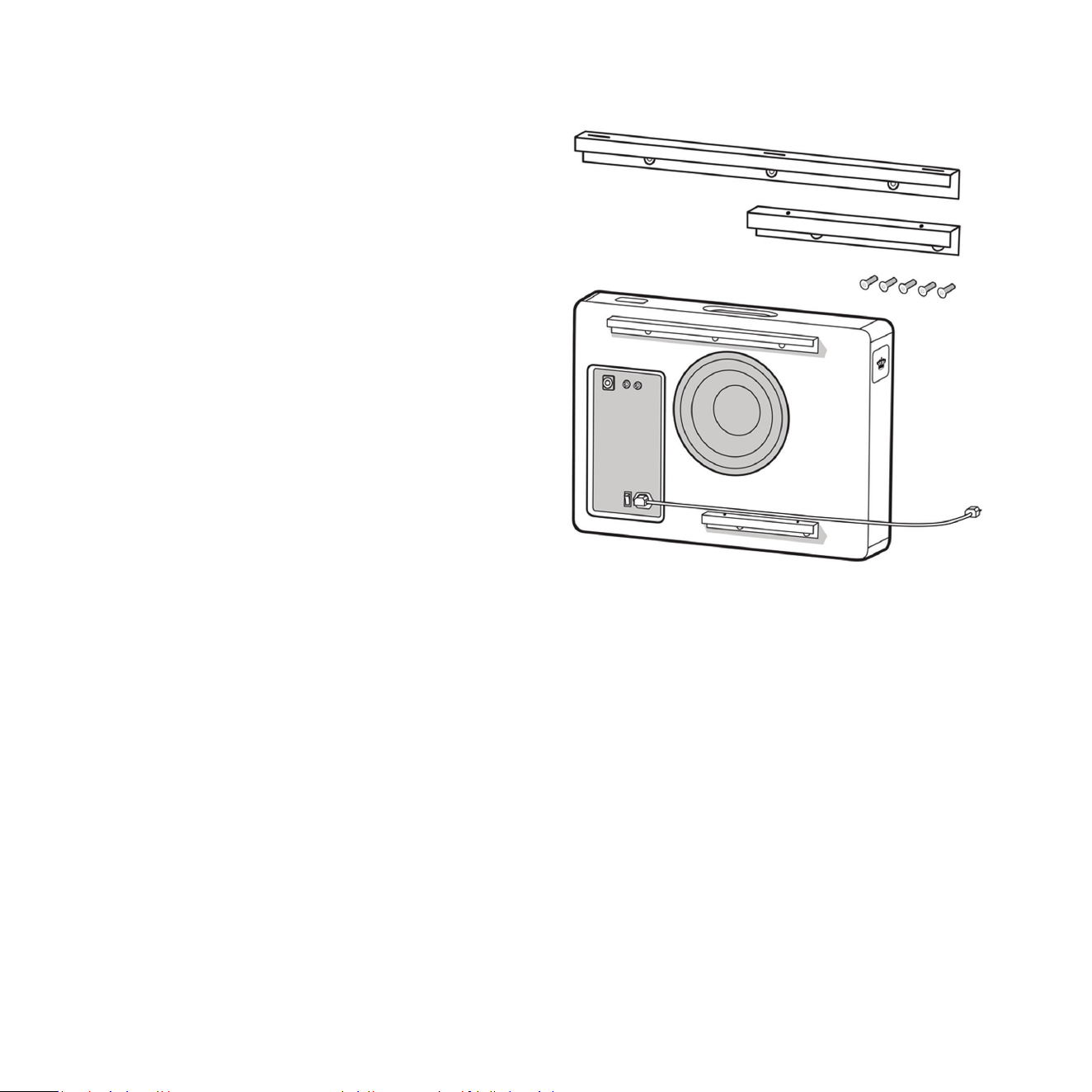
Start by bolng top bracket cabinet and boom bracket cabinet to the rear of your Planar using supplied
screws from package A. Take care to ne tune posioning to ensure they are as parallel with cabinet top as
possible. Having these brackets installed allows you to approximate the correct distance from the wall your
Planar will sit when installed and therefore allow for more accurate listening results.
Then connect the power cable to the unit and turn it on because you will need to listen while posioning.
If you are using the wireless connecon, the transmier will have to be connected to the system and paired
with the unit. If hard wiring, these connecons will need to be made to the back of the cabinet.
23
23
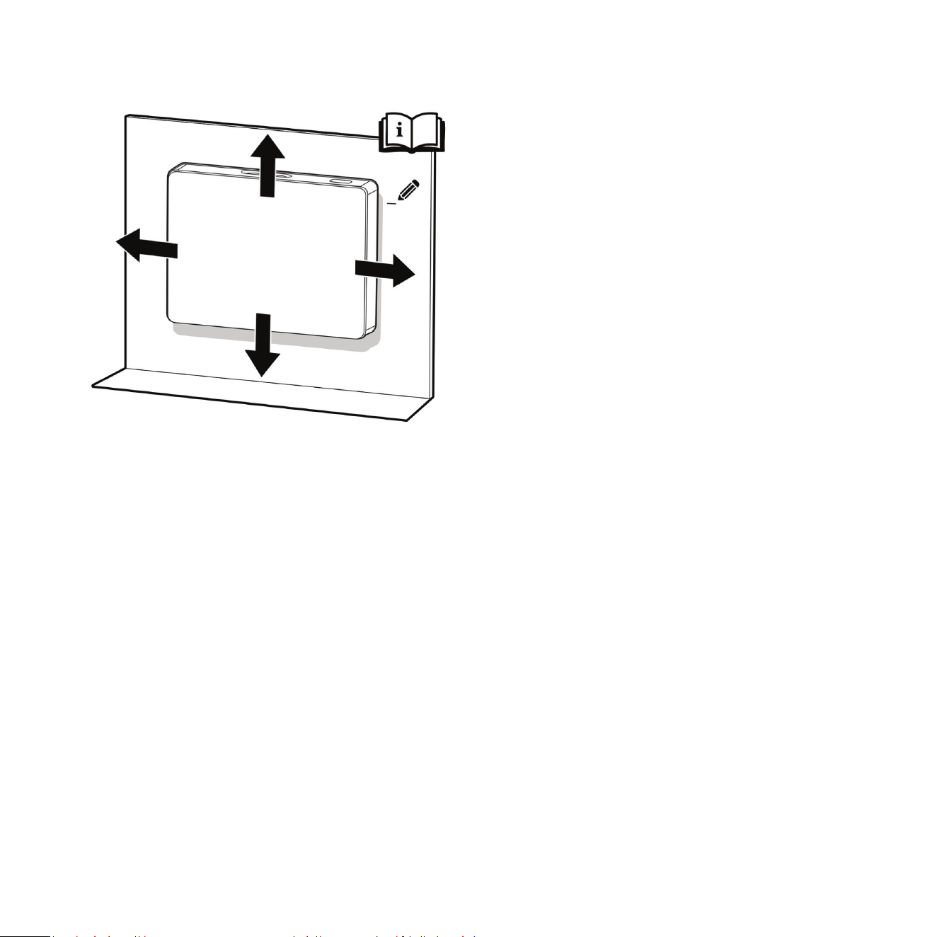
2 Posioning: The goal of this step is to pick the
best wall to posion Planar on a Planar Cart or
when mounng on a wall. If you already know
which wall you want to install the Planar on, move
to step 3. As you experiment with dierent wall
choices, try to hold Planar so that the boom of
the unit is 10 to 12in. (25 to 30 cm) o the ground.
This will provide an approximate locaon (we will
review le/right and up/down exact placement
next) and allow you to judge the merits of each
posion. Remember, while you may have several
wall choices the availability and locaon of studs
will impact your decision.
Front Wall Mounng: Mounng Planar on the
front wall of the room, in other words, the wall
that the main speakers are posioned in front of
will generate the best sonic results (same concept
with convenonal subwoofers). Front wall placement
allows for the most linear true low bass wave launch, creates the best sense of pressurizing the room, and
creates the best sense of keeping me and tempo with the music.
Side Wall Mounng: Side wall mounng works well also, just not quite as well as front wall mounng.
Nevertheless, quite high levels of performance are available from the side wall locaon, as long as the
subwoofer is located in the range between the front corner and the speaker locaon. In some instances,
it may be ne to place the Planar slightly in front of the main speaker (towards the listener), but moving
it too far along the side wall will result in the listener’s ability to locate it, reducing the seamless integrave
abilies inherent to the REL design.
If you are sll unsure about which wall to choose and have several opons with possible stud locaons
move on to step 3 which will further guide your decision.
3 Le/Right (Horizontal) Locaon: Now that you
have selected the wall for the Planar it is me
to determine the le/right locaon on the wall.
In some cases you will only have one opon (or
limited opons – typically standard walls only oer
2-3 useful locaons) based where the studs are
located. Keep the stud locaons in mind as you
complete this step because they dictate how much
movement le/right you have to experiment with.
Move the Planar along the wall in the le/right
plane stopping at each possible stud locaon with
the Planar approximately three feet o the ground
and the bracket distance away from the wall.
Listen for the best bass pressurizaon, extension,
and integraon at each locaon. Remember,
if you are using the side wall we suggest that you locate the Planar behind the main speakers if possible
(in the range between the front corner and the speaker locaon).
If you are sll unsure about which stud to choose on a parcular wall and have several opons move on to
step 4 which will further guide your decision.
4 Up/Down (Vercal) Locaon: Up unl this point we have suggested holding the Planar so that the boom
of the unit is approximately 10 to 12in. (25 to 30 cm) o the ground. While this is a good esmate to use
while choosing the wall and le/right locaon, to obtain the best possible performance the up/down locaon
placement is essenal. Just as you did previously, play a well-known piece of music with consistent, repevely
struck bass impulses and begin moving Planar up and down the line of the stud (make sure to locate the
edge of the bracket installed on the Planar to the stud locaon). Slowly moving the subwoofer up the stud
line on the wall, note and mark (lightly—no need to mark up your wall permanently) where the bass is
strongest. At rst, this may seem subtle, however, aer doing it for a short me you should start to hear
these stronger pulses quite clearly.
If you were previously unsure about which stud locaon to choose and have several opons do this up/down
listening test for all possible locaons and compare the results. This will help you make the best
overall decision.
24
25
User Hint: If using an AV processor/receiver with the REL HIGH-LEVEL cable make sure the speakers are
set to “Large” or “Full Range” in the sengs menu.
5 Selecng Locaon When Using Masonry Walls (Brick or Cement-based Building Blocks): All of the same
notes and suggesons apply to locang Planar in a room built using masonry. However, you are no longer
limited by stud locaons resulng in far more choices in placement. Use the same voicing technique
described above, and note that front wall placement sll generally results in the best overall performance.
6 Selecng Locaon When Using Plaster Walls: Plaster walls represent special challenges since the plaster
itself is exceponally brile. Unless you have extensive experience working with plaster walls, it is recommended
that installaon of Planar be performed by an experienced professional. Use the same voicing technique
described above, and note that front wall placement sll generally results in the best overall performance.
Posioning Using Planar Cart 1 or 2
Begin by installing your Planar on its Cart, using the instrucons supplied with the Cart. Make sure to install
the grille prior to installing it on the Cart as you will nd it impossible to do so once it is bolted to the Cart.
When used in a freestanding conguraon, REL strongly recommends installaon of the included an-p
restraint system. See the “Stability & An-Tip Safety” secon in this manual (page 38).
The Process PL-2 model: To begin dialing in
crossover, phase and gain please acquire the CD
of the 1994 movie Sneakers (the streaming version
which has inferior bass dynamics) and use track
four from the soundtrack to Sneakers (Columbia
CK 53146). This has a repeve bass drum
throughout that gives you plenty of me to move
the woofer around, but more importantly, the
concert bass drum is pitched at 32 Hz. This track
is perfect for dial-in of PHASE and CROSSOVER and
will get you close on gain. The overall system
volume should be at a level that a reasonable
person would describe as medium or medium
loud volume level.

26
The Process for PL-1 Model: All the same direcons both above and below are idencal with the excepon
of our guidance to use Rachelle Ferrell Cut Sista from her cd “Individuality: Can I be Me?”. This dierence of
setup material is necessary because the Planar PL-2 extends signicantly deeper and we nd that the same
results can be achieved on PL-1 with dierent program material. Set the controls to the following sengs:
Adjust the HI LEVEL to a point where the Planar and speaker are sure to share frequencies (about halfway up
or slightly higher for smaller speakers). Turn the HI LEVEL Gain control up so that the output of your Planar
and speakers are roughly equal in volume. For many speakers, this will be in the region of 9 to 11 o’clock.
We recommend using the HIGH-LEVEL connecon to obtain the best results.
Working with a partner, one in the listening posion and one at the Planar subwoofer manipulang its
controls and varying locaon, is the most eecve and ecient way to dial in your Planar when used as an
on-wall. If working alone, the inial step in the set-up can be very eecvely carried out from the locaon
of the Planar, however prior to making a nal determinaon rst narrow your selecon to the two best
sounding, then listen to each from your primary listening posion. Trying to ignore all other music in the
track, listen for the bass drum and its eect on the listening room.
1 PHASE 0 or 180?: Place Planar on the oor near the wall (use a clean and so towel or blanket to protect
the boom nish) using the installed bracket length away from the wall. Adjusng for phase may be the
single most crical step and, because it really is quite simple, it is oen over-thought. Keep in mind that the
correct phase is whichever posion produces the loudest output. Do not make the mistake of selecng the
wrong phase simply because you believe it sounds more delicate or “preer”. Louder is correct because it
is working with your speaker’s phase, not cancelling bass. Less bass occurs when it’s set incorrectly because
the incorrect phase seng results in cancellaon of energy.

27
2 Crossover and Level Sengs: REL controls have detents you can feel when rotang them. We refer to
these as clicks and use them to guide posions of these controls. To determine the crossover point, take the
volume of the REL (using the HI LEVEL control) all the way down, and set the CROSSOVER to its lowest seng.
While playing Cut 4 of Sneakers, begin bringing the REL’s Level control up one click at a me and pause at
the point where you have achieved balance, i.e. the point at which you can hear the REL even with the main
speakers playing. Now, bring the crossover control up (clockwse) 1 click at a me unl it is obviously too high;
at this point bring it down to the appropriate lower seng. This may be 1 click higher or lower than you
inially felt was right. For all intents and purposes, this is the correct crossover point. Once this stage has
been reached, subtle changes to LEVEL and CROSSOVER can be made to provide the last bit of complete
and seamless integraon.
Hint: There is a tendency to set the crossover point too high and the volume of the Sub-Bass System too
low when rst learning how to integrate a REL with the system, the fear being one of overwhelming the
main speakers with bass. But in doing so, the resulng set-up will be lacking in bass depth and dynamics.
The proper crossover point and volume seng will increase overall dynamics, allow for extended bass
frequencies, and improve soundstage properes. Note that volume must be adjusted in conjuncon with
crossover changes whenever one is increased check to ensure that the other doesn’t need to be reduced
by one click. In general, when selecng a lower crossover point, more volume level can be applied.
3 Final Checks: Now that your Planar has the proper sengs, conrm that you are sased with the wall
locaon you previously chose by liing it up in place as a nal check. If you are sased, you are now ready
to install the Planar as an on-wall subwoofer. Be sure to revisit step 2 aer you have properly installed the
Planar to make subtle changes to the crossover and gain sengs.
Other use cases
The primary use of Planar is to reinforce front le and right stereo speakers, but it can also be used in home
theatre and to reinforce inwall speakers. Connecon instrucons for these other use cases are available in
the previous secon of this manual, “Making Connecons” (page 15).

28
Centre Channel
The Planar (parcularly the PL-1) can be used as a dedicated centre channel subwoofer in a home theatre
system. The ideal placement is below or behind the centre channel speaker on the front wall. Connect
HIGH-LEVEL only, there is no need for Low Frequency Eects (LFE). For dedicated centre channel connecon
instrucons, see the Making Connecons secon (page 15). Begin with a lower crossover seng than used
for the main front channels and gradually increase the HI LEVEL control unl dialogue gains weight and
scale without sounding thick or unnatural. While adjusng sengs, listen carefully to spoken dialogue and
the sense of space around voices and on-screen eects. If dialogue begins sounding chesty or disconnected
from the screen, reduce the crossover or output level.
Rear Channel
Planar may also be used as a dedicated rear channel subwoofer in home theatre systems. The approach
to using the Planar with the rear channel of a home theatre is similar to the front channels, in that it will
provide low-frequency support for these specic speaker channels while also reinforcing LFE events. If only
one Planar is used in the front, it is best to place the rear Planar in the opposite corner. If stereo pairs of
Planar are used in the front, stereo rear Planars are recommended for best balance. For rear channel
applicaons, use both the HI LEVEL and .1/LFE INPUTS simultaneously. For connecon instrucons, see the
Making Connecons secon (page 15). Begin with lower output sengs than used for the front channel
Planars and adjust gradually. While tuning, listen for smooth movement of bass eects from the front to
rear of the room and a greater sense of space and immersion. If bass becomes distracng or easily localized
to the rear of the room, reduce output level or crossover frequency.
In Wall and In Ceiling Speakers
In-wall and in-ceiling speakers oen lack low-frequency extension and dynamic weight. Planar can be used
to restore balance and scale to these systems. Planar placement, connecon, and tuning generally follows
the same process described earlier in this manual. Whenever possible, front wall placement is recommended
for the best integraon and overall performance. For music-focused systems, use the High-Level connecon.
For systems used for both music and home theatre, use both the HI LEVEL and .1/LFE INPUTS simultaneously.
See the Making Connecons (page 15) and REL Set-Up Made Simple secons (page 21) for setup and
connecon instrucons. While adjusng crossover and level sengs, listen for improved weight, scale, and
integraon in the overall system without drawing aenon to the Planar itself. If the bass becomes overly
dominant or detached from the main speakers, reduce crossover or output level.
29
29
Before beginning the installaon process, read the REL Setup Made Simple secon (page 21) for instrucons
about how to select the best locaon for Planar.
The following step by step instrucons guide a Planar user in mounng the cabinet to a typical home wall
made of studs with drywall nish or brick masonry walls. The Planar must be securely anchored to the wall.
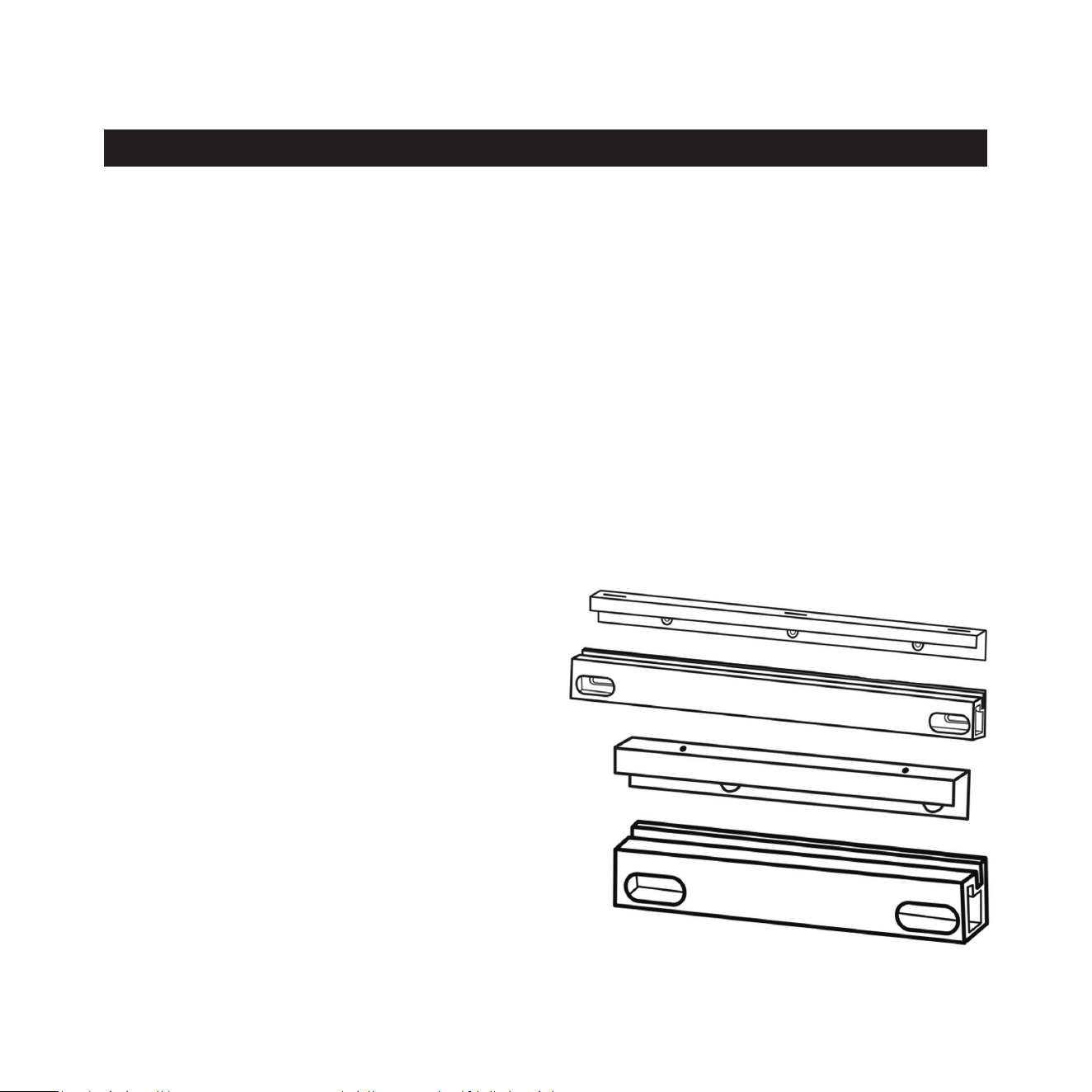
There are two sets of mounng brackets for the Planar cabinet. Each set is made up of a wall side bracket
and a cabinet side bracket that are designed to t together to create a solid mounng for the Planar.
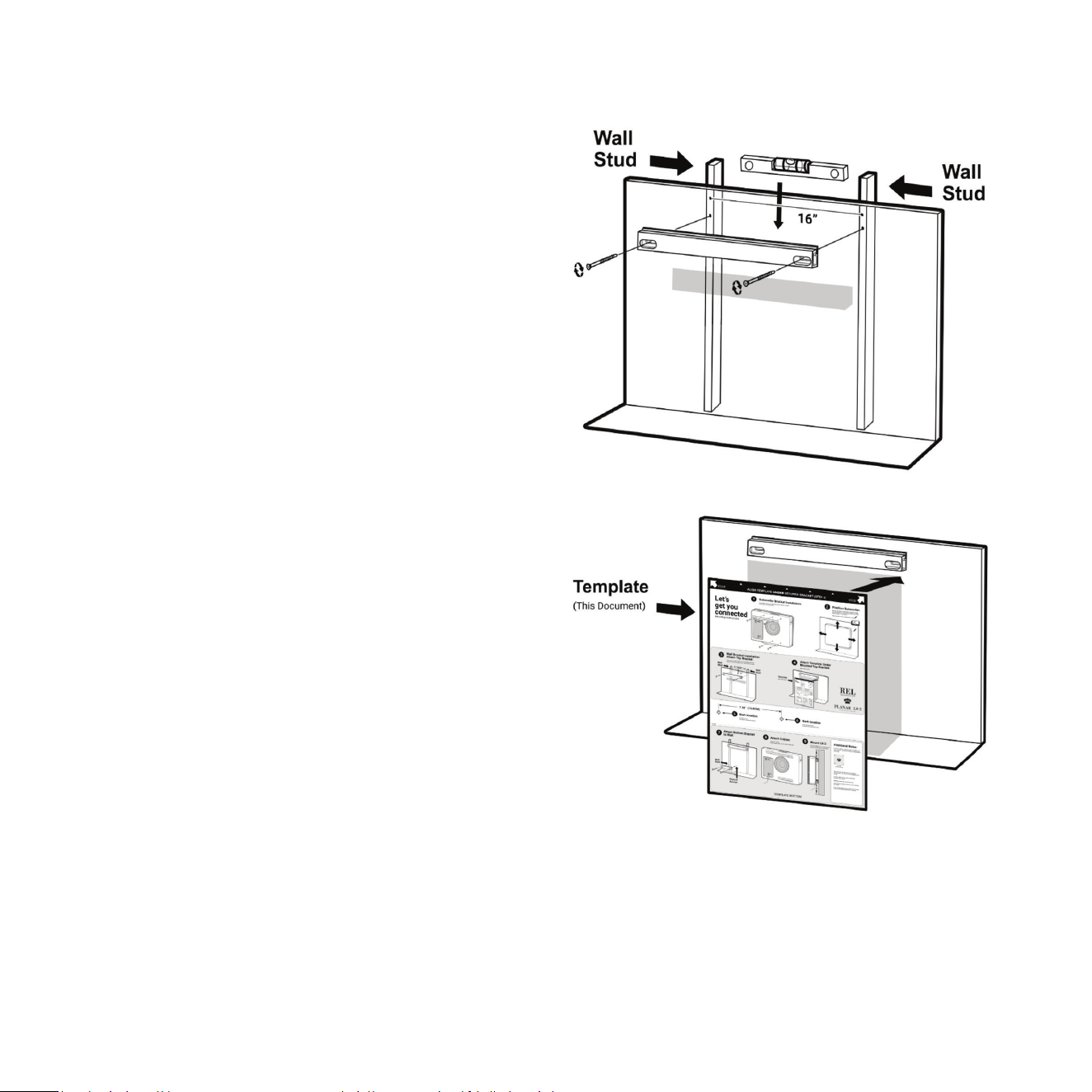
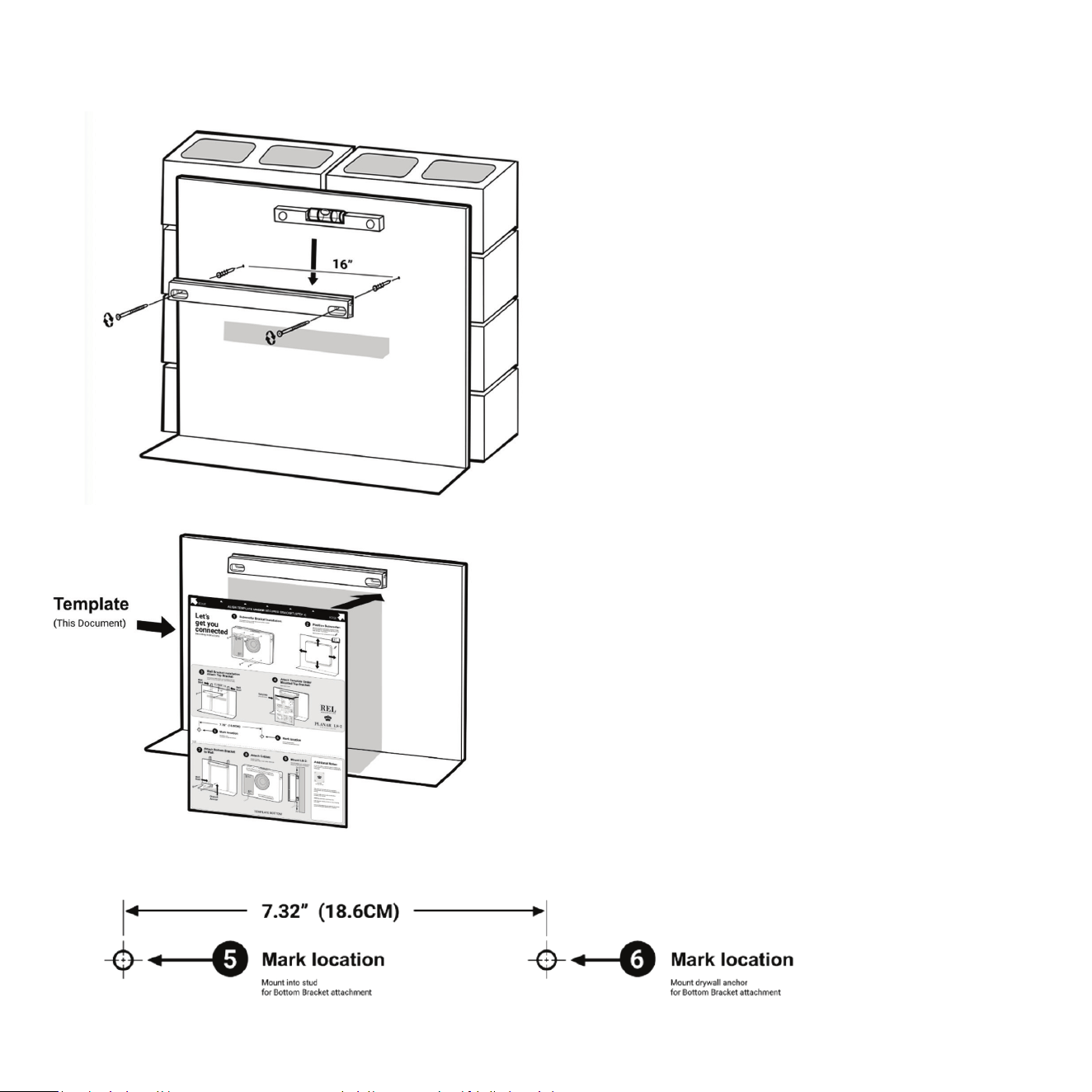
Stud Wall Mounng
The top bracket spans most of the length of the cabinet and should get mounted to two studs that are
400mm (16in.) apart. The boom bracket is shorter and should get anchored to one stud and a sturdy
drywall mount. Both brackets are required for the Planar to funcon properly. Two people are recommended
for proper installaon.
Supplied Hardware
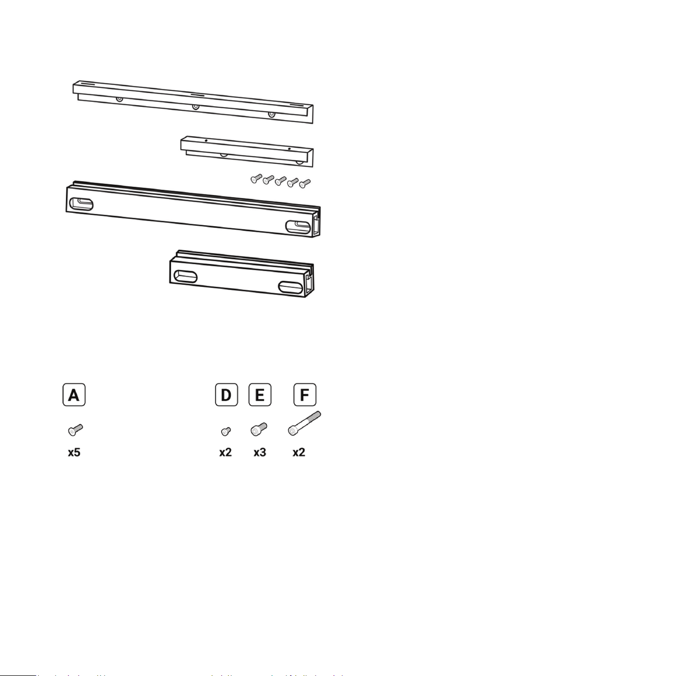
Top Bracket Wall (long wall bracket)
Top Bracket Cabinet (long cabinet bracket)
Boom Bracket Wall (short wall bracket)
Boom Bracket Cabinet (short cabinet bracket)
Mounng
30
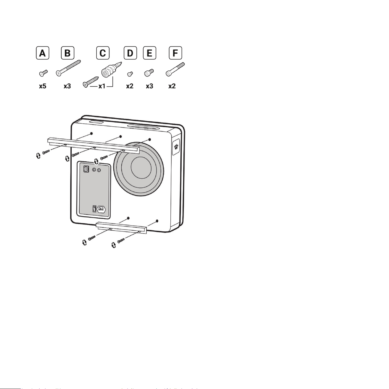
A Flat head screw M6 thread, 4mm hex drive,
18mm length (x5)
B Flat head wood screw Size 8, 1-¾in. length (X3)
C Self drilling #9 drywall anchor with at head
wood screw Size 9, 1-¼in. length
D Socket cap screw M3 thread, 2.5mm hex drive,
8mm length, pre-installed on bracket (x2)
E Socket cap screw M6 thread, 5mm hex drive,
14mm length (x3)
F Socket cap screw M6 thread, 5mm hex drive,
50mm length (x2)
Gasket long
Gasket short
Wall mount template
4mm hex driver
5mm hex driver
Required (not supplied)
Philips screwdriver
Pencil
Drill / driver
3/32in. drill bit
14in. ruler or tape measure
Level
Glue
Stud nder
Medium adhesion painter’s tape
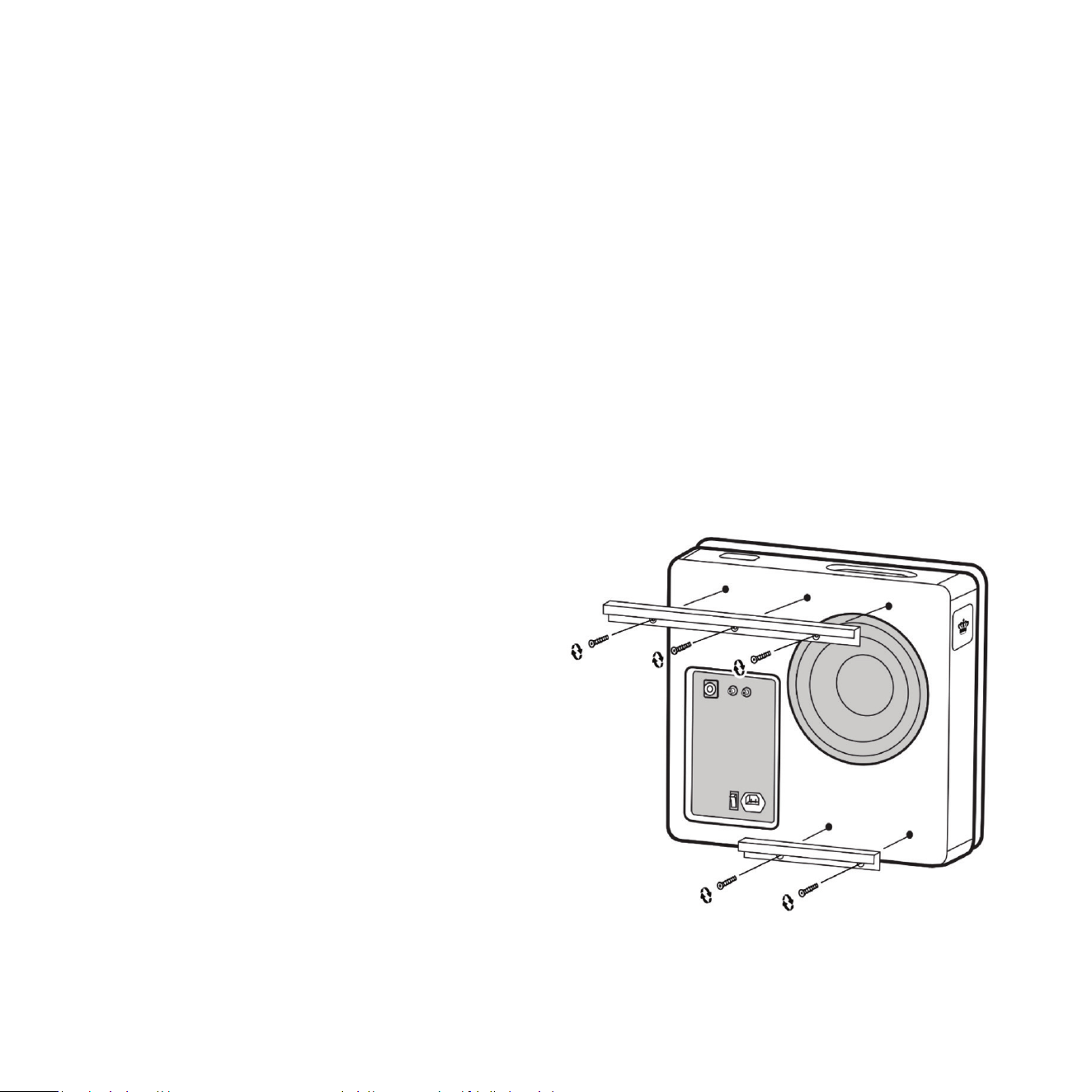
1 Remove grille and set aside on a clean surface.
2 Mount cabinet side brackets (Top and Boom)
to the cabinet using at head screws. This step
should have been completed in the REL Setup
Made Simple secon.
3 Determine placement of the Planar. See the REL
Setup Made Simple secon of this manual.
4 Locate nearest studs to opmum placement.
Planar must be installed onto wall studs. Our
suggeson is to use an electronic stud nder
and follow the manufacturer’s guidance.
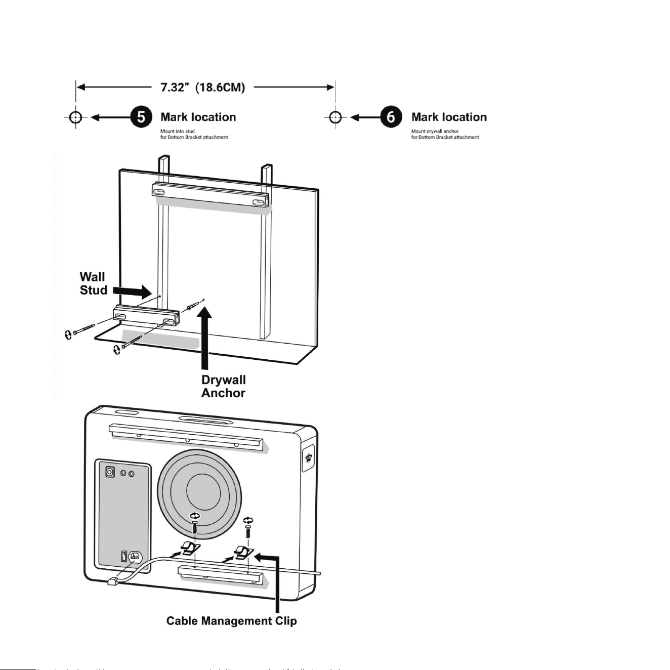
5 Holding the cabinet in place on the wall, mark
the wall along the top edge of the top bracket
and at the right corner.
6 Next, hold Top Wall Bracket to the wall below
the mark from the top bracket.
7 Level the bracket against the wall and mark the
screw hole locaons. Make sure that the screws
will hit the studs.
8 Drill a pilot hole for each screw hole using the
drill / driver and 3/32in. drill bit.
9 Place long gasket on the back side of the Top
Wall Bracket. Gasket must go between wall and
bracket. Do not omit the use of this gasket.
10 Screw top bracket to wall using supplied Flat
head wood screws Size 8 screws. Make sure
screws are ght and the bracket is mounted
securely to the wall but not compressing
the gasket.
11 With top wall bracket in place, use the supplied
wall mount template to locate the holes for
the boom wall bracket. The supplied template
works for wall studs that are about 400mm
(16in.) apart. Place template directly under top
wall bracket and mark the holes indicated for
your wall construcon.
31
12 The le side screw hole for boom wall
bracket should be directly below that of the
top bracket and there should be a wall stud
behind it.
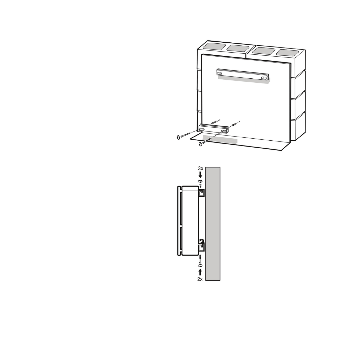
13 Drill a pilot hole for the two screw holes using
the drill / diver and 3/32in. drill bit.
14 The right screw hole will require a drywall
anchor. Use glue on the threads when installing
this anchor to the drywall. The type of anchor
supplied will cut its own hole as you screw it in.
15 Place short gasket on the back side of wall
bracket C. Gasket must go between wall and
bracket. Do not omit the use of this gasket.
16 Screw boom bracket to wall with drywall
screws. Make sure screws are ght and bracket
is mounted solid to wall but not compressing
the gasket.
17 Connect AC cable provided to back panel of
Planar and install AC cable clips to dress the
cable along the boom bracket. Remember
to turn the AC switch on because this will be
dicult once the Planar is mounted.
18 Li cabinet to wall and lower onto brackets.
32
33
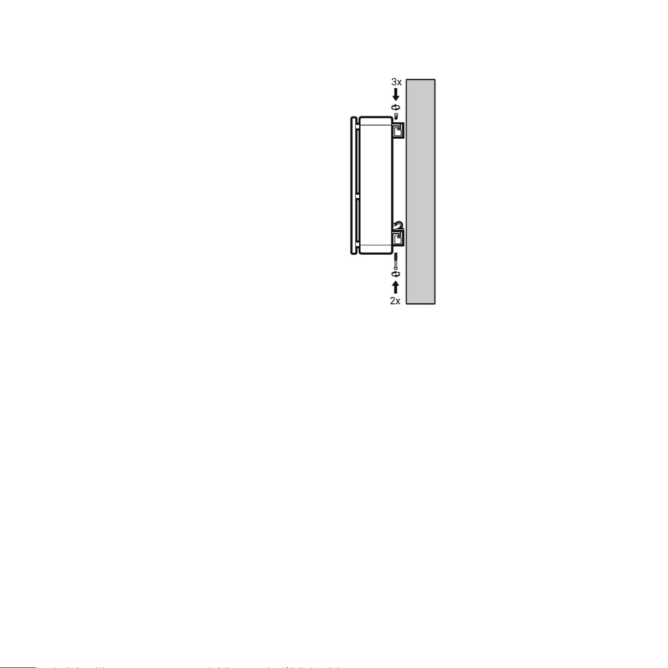
19 The t will be snug. Draw the cabinet into
place using the three 18mm long cap head
top mounng hardware. Tighten the three
provided screws 1/2 turn at a me starng
with one side and rotang through each one.
Using this method will take several passes to
get the screws ght. You will noce that with
each pass the Planar is evenly pulled into
the bracket.
20 Secure boom bracket with the two 50mm
long cap head hardware provided from the
boom side of the bracket.
21 Install Grille.
Now that the Planar subwoofer is mounted to the wall, it is me to revisit the sengs to really dial in
the system.
Crossover and Level Sengs: To determine the crossover point, take the volume of the REL (using the
HI LEVEL control) all the way down, and put the CROSSOVER to 25 Hz. At this point bring the REL’s volume
back up slowly to the point where you have achieved a subtle balance, i.e. the point at which you can hear
the REL even with the main speakers playing. Now, bring the crossover point up unl it is obviously too high;
at this point bring it down to the appropriate lower seng. For all intents and purposes, this is the correct
crossover point. Once this stage has been reached, subtle changes to level and crossover can be made to
provide the last bit of complete and seamless integraon.
Hint: There may be a tendency to set the crossover point too high and the volume of the Sub-Bass System
too low when rst learning how to integrate a REL with the system, the fear being one of overwhelming
the main speakers with bass. But in doing so, the resulng set-up will be lacking in bass depth and dynamics.
The proper crossover point and volume seng will increase overall dynamics, allow for extended bass
frequencies, and improve soundstage properes. Note that volume must be adjusted in conjuncon with
crossover changes. In general, when selecng a lower crossover point, more volume may need to be applied.
3534
Solid Wall Mounng
Before beginning the installaon process, read the
REL Setup Made Simple secon for instrucons
about how to select the best locaon for Planar.
Wall anchors will be required to screw the top and
boom brackets to the wall. The supplied set of
brackets should work with all types of solid walls.
Both brackets are required for the Planar to
funcon properly. Two people are recommended
for proper installaon.
Supplied Hardware
Top Bracket Wall(long wall bracket)
Top Bracket cabinet (long cabinet bracket)
Boom Bracket Wall (short wall bracket)
Boom Bracket cabinet (short cabinet bracket)
A Flat head screw M6 thread, 4mm hex drive,
18mm length (x5)
D Socket cap screw M3 thread, 2.5mm hex drive,
8mm length, pre-installed on bracket (x2)
E Socket cap screw M6 thread, 5mm hex drive,
14mm length (x3)
F Socket cap screw M6 thread, 5mm hex drive,
50mm length (x2)
Gasket long
Gasket short
Self drilling #9 drywall anchor
Wall mount template
4mm hex driver
5mm hex driver
Required (not supplied)
Philips screwdriver
Pencil
Drill / driver
14in. ruler or tape measure
3/16in. masonry drill bit
5/16in. masonry drill bit
Glue
Medium adhesion painter’s tape
Hammer
Size 8 Masonry anchors (X4)
Level
1 5/8in. ne thread drywall screws (x4)
(This is a suggested length. Your wall may require
longer screws)
1 Remove grille and set aside on a clean surface.
2 Mount cabinet side brackets (Top and Boom)
to the cabinet using at head screws. This step
should have been completed in the REL Setup
Made Simple secon.
3 Determine placement of the Planar. See the REL
Setup Made Simple secon of this manual.
4 Holding the cabinet in place on the wall, mark
the wall along the top edge of the top bracket
and at the right corner.
5 Next hold Top Wall bracket to the wall below
the mark from the top bracket.
35
36
6 Level the bracket against the wall and mark the
screw hole locaons.
7 Drill a pilot hole for each screw hole using the
drill / driver and 3/16in. drill bit.
8 Drill hole for anchors using the drill / driver and
5/16in. drill bit.
9 Put glue on masonry anchors before installing.
10 Push masonry anchor into wall and drive ush
with hammer.
11 Place long gasket on the back side Top Bracket
Wall. Gasket must go between wall and bracket.
Do not omit the use of this gasket.
12 Screw top bracket to wall using screws. Make
sure screws are ght and bracket is mounted
securely to wall but not compressing the gasket.
13 With top wall bracket in place, use the supplied
wall mount template to locate the holes for
the boom bracket. This template should
work for all solid walls. Place template directly
under top wall bracket and mark the holes
indicated for your wall construcon.
14 Drill a pilot hole for the two screw holes using
the drill / diver and 3/16in. drill bit.
15 Drill hole for anchors using the drill / driver
and 5/16in. drill bit.
37
16 Put glue on masonry anchors before installing.
17 Push masonry anchor into wall and drive ush
with hammer.
18 Place short gasket on the back side of Boom
Bracket Wall. Gasket must go between wall
and bracket. Do not omit the use of this gasket.
19 Screw boom bracket to wall using screws.
Make sure screws are ght and bracket is
mounted securely to wall but not compressing
the gasket.
20 Connect AC cable provided to back panel of
Planar and install AC cable clips to dress the
cable along the boom bracket. Remember
to turn the AC switch on because this will be
dicult once the Planar
is mounted.
21 Li cabinet to wall and lower onto brackets.
22 The t will be snug. Draw the cabinet into
place using the three 13.5mm long cap head
top mounng hardware. Tighten the three
provided screws 1/2 turn at a me starng
with one side and rotang through each one.
Using this method will take several passes to
get the screws ght. You will noce that with
each pass the Planar is evenly pulled into
the bracket.
23 Secure boom bracket with the two 50mm
long cap head hardware provided from the
boom side of the bracket.
24 Install Grille

38
Now that the Planar Sub-Bass System is mounted to the wall, it is me to revisit the sengs to really dial in the system.
Crossover and Level Sengs: To determine the crossover point, take the volume of the REL (using the
HI LEVEL control) all the way down, and put the CROSSOVER to 25 Hz. At this point bring the REL’s volume
back up slowly to the point where you have achieved a subtle balance, i.e. the point at which you can hear
the REL even with the main speakers playing. Now, bring the crossover point up unl it is obviously too high;
at this point bring it down to the appropriate lower seng. For all intents and purposes, this is the correct
crossover point. Once this stage has been reached, subtle changes to level and crossover can be made to
provide the last bit of complete and seamless integraon.
Hint: There may be a tendency to set the crossover point too high and the volume of the Sub-Bass System
too low when rst learning how to integrate a REL with the system, the fear being one of overwhelming the
main speakers with bass. But in doing so, the resulng set-up will be lacking in bass depth and dynamics.
The proper crossover point and volume seng will increase overall dynamics, allow for extended bass
frequencies, and improve soundstage properes. Note that volume must be adjusted in conjuncon with
crossover changes. In general, when selecng a lower crossover point, more volume may need to be applied.
Stability & An-Tip Safety
Planar is designed to be mounted to a wall or used in close relaonship with a wall for opmal performance.
When used in a freestanding posion, it may p if subjected to sucient force.
REL strongly recommends installing the included an-p restraint in all freestanding applicaons, especially
in environments with children, pets, or high foot trac.
39
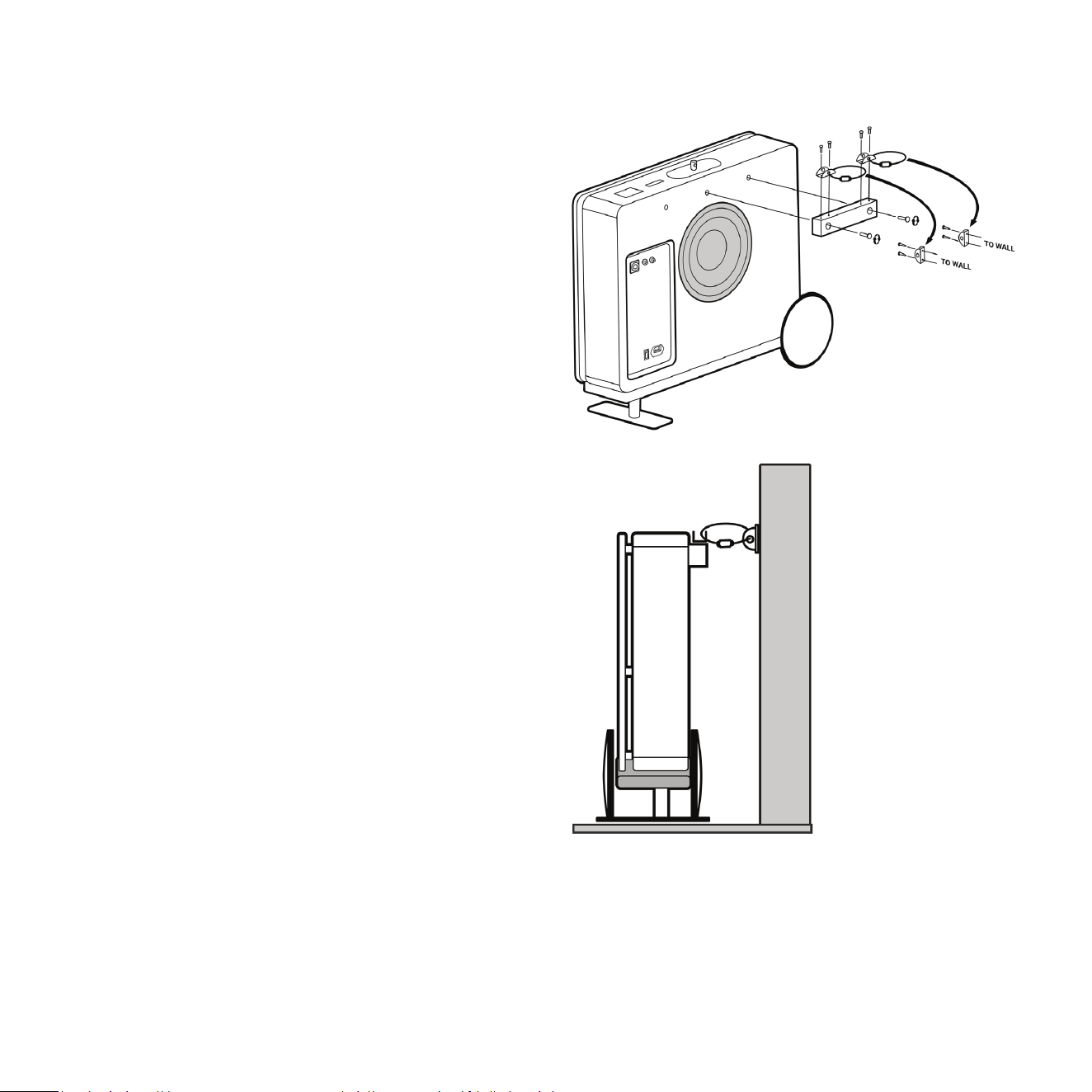
Installing the An-Tip Restraint
The An-Tip Restraint is comprised of a wall tether
block that will mount onto the back of your Planar
Sub-Bass System’s cabinet, hardware that will
screw into your wall, and a tether that will anchor
these pieces together. For safe operaon when
Planar is used in a freestanding posion, install the
included an-p restraint as follows:
1 Secure the wall tether block to the subwoofer’s
cabinet, using the supplied bolts (two from
package A). This block and the bolts are designed
to mount to the centre and upper-right inserts
found on the rear face of the Planar subwoofer’s
cabinet.
2 Secure the two included loose anchors to your
wall. Each anchor uses two screws for securing
to the wall. We recommend marking the screw
locaons with a pencil, drilling pilot holes using
a 6mm drill bit, then pressing the plasc drywall
anchors into the pilot holes. You can then screw
in the metal anchors.
3 Once the anchors are installed onto your wall and
the tether block is installed onto the subwoofer,
you can use the two supplied cables for securing
each anchor on the block to the corresponding
anchor on your wall.
Use of the an-p restraint is the primary method
of prevenng p-over when Planar is used in a
freestanding posion.

40
Running In
Care taken over running in will be rewarded by many years of pleasurable use. Both the electronics and the
drive unit will benet from an inial period of carefully controlled use. Possible damage may be sustained
by running in the unit at too high a volume seng over an extended period. On the other hand, by taking a
lile care over this inial period, about 24 hours of actual use, a longer life with an eventual higher potenal
performance is assured.
Care and Polishing
The cabinets are best maintained by using a light automove spray-on wax and a micro ber cloth. (We use
a spray-on made by a company called Griot’s Garage™. While this may not be available in all markets, you
can use a similar product). Take care not to spray the aluminum badge. Do not place objects, such as drinks
on top of your REL Planar. Never use a dry cloth on this nish.
Technical
The AirShip Direct™ transmier provides true REL Theatre Reference™ connecvity, perming both HIGH-LEVEL
and LFE channels to be wirelessly fed to Planar. This occurs with virtually zero delay and a complete absence
of compression.
Planar uses a very fast, gentle and transparent lter intended to allow excellent impulse response and a
natural sound. We refer to this circuit as Natural Rollo™. Most subs use slow, very steep lters that lend an
unnatural, machine-like quality to the sound. The Planar employs a highly rened Class-D amplier which
combines high performance and high eciency. The drivers are simple, rugged and relavely light, and
yet oers excellent self-damping so we are beer able to reproduce the nuance of music and preserve the
explosiveness of transients. Finally, the cabinets, apart from being physically beauful, are like nely tuned
instruments that are largely responsible for the sonic virtue with which the Planar is imbued.

Type: (2) Front-ring acve woofers, (1) Rear-ring passive radiator
Drive Unit: (2) 6.5in. (165mm) FibreAlloy cone, long-throw, steel chassis
Passive Unit: 10in. (250mm) FibreAlloy cone, steel chassis
Lower Frequency Response: -6 dB at 31 Hz, in room
Input Connectors: HIGH-LEVEL Neutrik SpeakOn, LOW-LEVEL RCA, LFE RCA
Gain Control Range: 80 dB
Power Output: 300 was (RMS)
Phase Switch: Yes, 0 or 180 degrees
Amplier Type: Pure Class D™
Protecon System: Fully Electronic SET-SAFE
D.C. Fault: Yes
Output Short: Yes
Mains Input Voltage: 100-240 volts selectable
Fuse: 2.5A for 230V operaon
5A for 120V operaon
Dimensions (WHD): 20.6 x 19.4 x 5.7in. (522 x 492 x 144mm)
add 1.5in. (39mm) depth for on wall bracket
Net Weight: 41.6lbs. (18.9 kg)
Finish: Gloss Piano Black or Gloss White Lacquer
Supplied Accessories
Mains Lead: Yes, 90 degree to permit on wall mounng
Neutrik SpeakOn Interconnect: Yes. 1.5m cable intended for use with AirShip Direct™ transmier
User Manual: Yes
PL-1 Specicaons

Type: (1) Front-ring acve woofer, (1) Rear-ring passive radiator
Drive Unit: 8in. (205mm) FlatPiston™ acve long-throw, steel chassis
Passive Unit: 10in. (250mm) FibreAlloy cone, steel chassis
Lower Frequency Response: -6 dB at 24 Hz, in room
Input Connectors: HIGH-LEVEL Neutrik SpeakOn, LOW-LEVEL RCA, LFE RCA
Gain Control Range: 80 dB
Power Output: 550 was (RMS)
Phase Switch: Yes, 0 or 180 degrees
Amplier Type: Pure Class D™
Protecon System: Fully Electronic SET-SAFE
D.C. Fault: Yes
Output Short: Yes
Mains Input Voltage: 100-240 volts, selectable
Fuse: 4A for 230V operaon
8A for 120V operaon
Dimensions (WHD): 25.6 x 18.9 x 5.7in. (650 x 480 x 144mm)
add 1.5in. (39mm) depth for on wall bracket
Net Weight: 44.6lbs. (20.25 kg)
Finish: Gloss Piano Black or Gloss White Lacquer
Supplied Accessories
Mains Lead: Yes
Neutrik SpeakOn Interconnect: Yes 1.5m cable intended for use with AirShip Direct™ transmier
User Manual: Yes
PL-2 Specicaons

AirShip Direct™ Transmier Specicaons
Input Connectors: HIGH-LEVEL Neutrik SpeakOn, L/R LOW-LEVEL RCA, LFE single phono RCA,
LFE balanced XLR
Input Impedance
HIGH-LEVEL: 150k ohms
LOW-LEVEL: 10k ohms
RCA .1/LFE: 10k ohms
XLR .1/LFE: 10k ohms
Wireless output power: Less than -3dBm
Wireless eecve distance: 30 (10 meters) with clear line of site
Mains Input Voltage: 5V DC, 5.5mm circular connector, posive centre
Power consumpon: 0.6 Was
Dimensions (WHD): Transmier 8.5 x 8.5 x 1.8in., (215.5 x 215.5 x 46.5mm)
Receiver 3.15 x 2.40 x 0.7in., (80 x 60 x 17.5mm)
Finish: Black
Supplied Accessories: Power adapter, HIGH-LEVEL cable, X2 RCA cable
In the interest of product improvement, REL Acouscs Limited reserves the right to alter these specicaons without noce.

REL Acouscs Limited
North Road, Bridgend industrial Estate . Bridgend, CF31 3TP . United Kingdom
Telephone: +44 (0)1 656 768 777 . Fax: +44 (0) 1 656 766 093
Web: www.rel.net
PL-1 or PL-2 Subwoofer
Cloth Grille
Airship Direct Wireless System (with receiver unit pre-installed on subwoofer)
Right-Angle Power Cord
Control Panel Cover
Owner’s Manual
Wall Mounng Template
Wall Mounng Brackets
VIMAR Material for Wall Mounng
One (1) 4mm Allen/Hex Wrench
One (1) 5mm Allen/Hex Wrench
Flat head screw M6 thread, 4mm hex drive, 18mm length (x6)
Socket cap screw M6 thread, 5mm hex drive, 50mm length (x2)
Socket cap screw M6 thread, 5mm hex drive, 14mm length (x3)
Self drilling #9 drywall anchor (x2)
Flat head wood screw Size 9, 1-¼in. length (x2)
Flat head wood screw Size 8, 1-¾in. length (x4)
Two (2) Cable Retainer Clips, pre-installed to lower bracket
What Comes Packed with Planar Series Subwoofers

REL Acouscs Limited
North Road, Bridgend industrial Estate . Bridgend, CF31 3TP . United Kingdom
Telephone: +44 (0)1 656 768 777 . Fax: +44 (0) 1 656 766 093
Web: www.rel.net