
REL Acouscs Limited
North Road, Bridgend industrial Estate . Bridgend, CF31 3TP . United Kingdom
Telephone: +44 (0)1 656 768 777 . Fax: +44 (0) 1 656 766 093
Web: www.rel.net
Operang Instrucons for the
Serie S
Sub-Bass System
REL Acouscs Limited
North Road, Bridgend industrial Estate . Bridgend, CF31 3TP . United Kingdom
Telephone: +44 (0)1 656 768 777 . Fax: +44 (0) 1 656 766 093
Web: www.rel.net
2
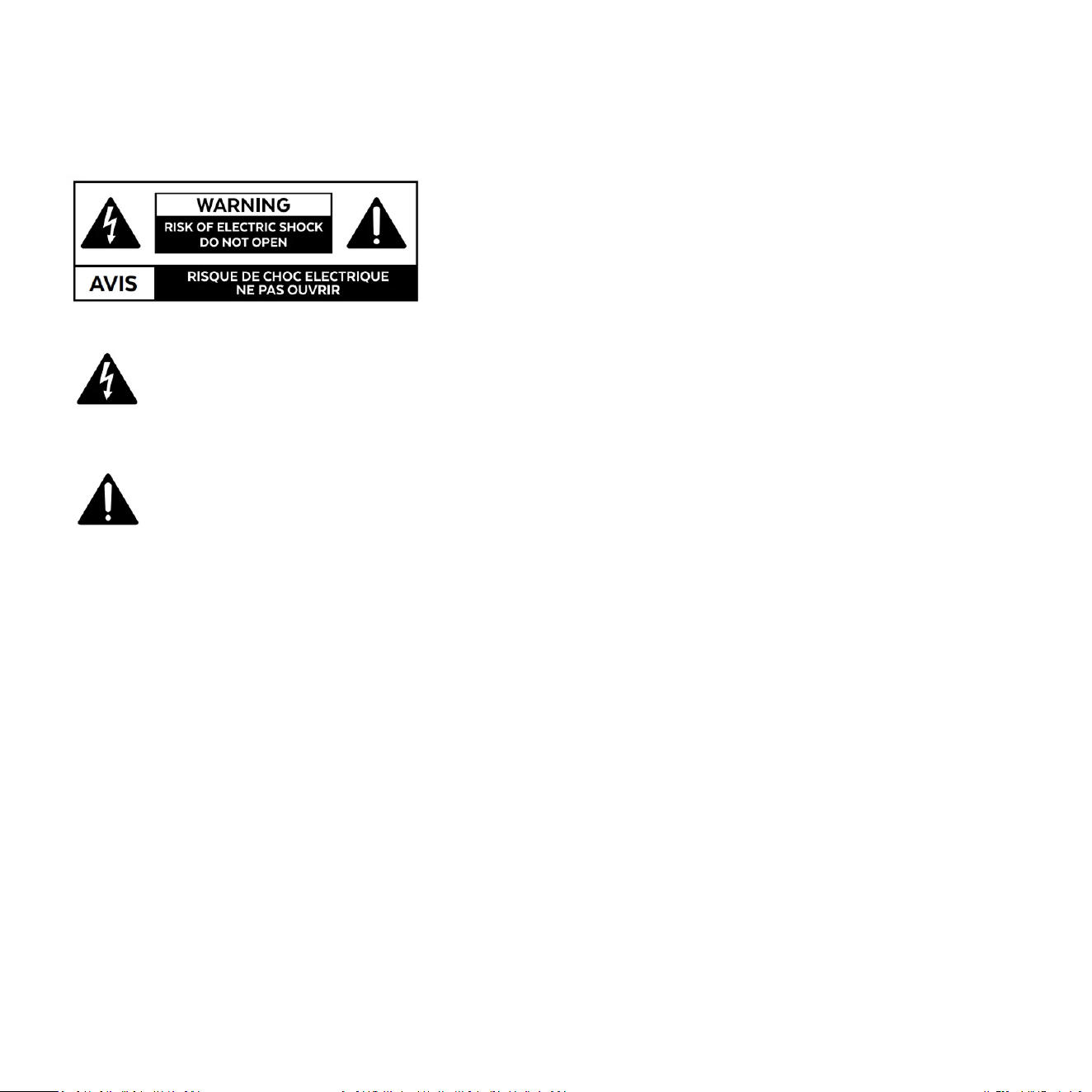
Cauon Marking Explanaon
The lightning ash with arrowhead symbol within an equilateral triangle is intended to alert the user
to the presence of un-insulated dangerous voltage within the product’s enclosure that may be of
sucient magnitude to constute a risk of electric shock to persons.
The exclamaon point within an equilateral triangle is intended to alert the user to the presence of
important operang and maintenance (servicing) instrucons in the literature accompanying the
appliance.

2
1 Read all of these instrucons.
2 Save these instrucons for future use.
3 Heed all warnings.
4 Follow all instrucons.
5 Do not use this apparatus near water.
6 Clean only with automove polish and micro ber cloth.
7 Install in accordance with the manufacturer’s instrucons.
8 Do not install near any heat sources such as radiators, heat registers, stoves or other apparatus (including
ampliers) that produce heat.
9 Do not defeat the safety purpose of the grounding-type plug. A grounding type plug has two blades and
a third grounding prong. The third prong is provided for your safety. If the provided plug does not t into
your outlet, consult and electrician for replacement of the obsolete outlet.
10 Protect the power cord from being walked on or pinched parcularly at plugs, convenience receptacles,
and the point where they exit from the apparatus.
11 Only use aachments/accessories specied by the manufacturer.
12 Use only with a cart, stand, tripod, bracket, or table specied by the manufacturer, or sold
with the apparatus. When a cart is used, use cauon when moving the cart/apparatus
combinaon to avoid injury from p-over.
13 Unplug this apparatus during lightning storms or when unused for long periods of me.
14 Refer all servicing to qualied service personnel. Servicing is required when the apparatus has been
damaged in any way, such as power-supply cord or plug is damaged, liquid has been spilled or objects
have fallen into the apparatus, the apparatus has been exposed to rail or moisture, does not operate
normally, or has been dropped.
15 minimum distances 10cm around the apparatus for sucient venlaon;
Important Safety Instrucons

4
3
16 the venlaon should not be impeded by covering the venlaon openings with items, such as newspa-
pers, table-cloths, curtains, etc.;
17 no naked ame sources, such as lighted candles, should be placed on the apparatus;
18 aenon should be drawn to the environmental aspects of baery disposal;
19 the use of apparatus in moderate climates.
20 Baeries shall not be exposed to excessive heat such as sunshine, re or the like.
Cauon: Any changes or modicaons not expressly approved by the party responsible for compliance
could void the user’s authority to operate this equipment.
Warning
To reduce the risk of re or electric shock, do not expose this apparatus to rain or moisture.
The apparatus shall not be exposed to dripping or splashing and no objects lled with liquids, such as vases,
shall be placed on apparatus.
The mains plus is used as disconnect device. The mains plug of the apparatus should not be obstructed OR
should be easily accessed during intended use. To be completely disconnected from the power input, the
mains plug of the apparatus shall be disconnected from the mains.
An appliance with a protecve earth terminal should be connected to a mains outlet with a protecve
earth connecon.
Design Safety
These apparatus are supplied with a detachable mains cord. For 230V operaon a 8A fuse is ed in the
socket of the S/850 and a 5A fuse is ed in the socket of the S/550, for 120V operaon a 15A fuse is ed
for the S850 and a 10A fuse is ed for the S/550. Should the fuse need to be replaced use a similar rated
fuse approved to ASTA or BSI 362 standards. Do not use without the fuse cover in place. Replacement fuse
covers are available from your distributor.
4
Aenon Explicaon Marquage
L’éclair avec le symbole de pointe de èche dans un triangle équilatéral est desné à alerter
l’ulisateur de la présence de non isolée tension dangereuse à l’intérieur de l’enceinte du
produit qui peut être d’une ampleur susante pour constuer un risque d’électrocuon pour
les personnes.
Le point d’exclamaon dans un triangle équilatéral est desné à alerter l’ulisateur de la
présence d’instrucons dans la documentaon accompagnant l’appareil exploitaon et de
maintenance (entreen).

5
1 Lisez aenvement ces instrucons.
2 Conservez ces instrucons.
3 Respectez tous les averssements.
4 Suivez toutes les instrucons.
5 Ne pas uliser cet appareil près de l’eau.
6 Neoyez seulement avec du vernis automobile et ssu microbre.
7 Installer conformément aux instrucons du fabricant.
8 Ne pas installer près de sources de chaleur telles que des radiateurs, registres de chaleur, poêles ou
autres appareils (y compris les amplicateurs) qui produisent de la chaleur.
9 Ne pas contourner le disposif de sécurité de la prise de terre. Une che de terre a deux lames et une
troisième broche de mise à la terre. La troisième broche est fournie pour votre sécurité. Si la che fournie
ne rentre pas dans votre prise, consultez un électricien pour le remplacement de la prise obsolète.
10 Protégez le cordon d’alimentaon ne soit piéné ou pincé, en parculier au niveau des ches, des prises
de courant, et le point de sore de l’appareil.
11 Ulisez uniquement des xaons / accessoires spéciés par le fabricant.
12 Ulisez seulement avec un chariot, stand, trépied, support ou table spécié par le fabri
cant, ou vendu avec l’appareil. Lorsque vous ulisez un chariot, soyez prudent lorsque vous
déplacez l’ensemble
chariot / appareil pour éviter les blessures en cas de chute.
13 Débranchez cet appareil pendant un orage ou lorsqu’il est inulisé storsm pour de longues périodes de temps.
14 Conez toute réparaon à un personnel qualié. Une réparaon est nécessaire lorsque l’appareil a été
endommagé de quelque façon que ce cordon d’alimentaon ou la che est endommagé, du liquide a
été renversé ou des objets sont tombés dans l’appareil, l’appareil a été exposé à rail ou à l’humidité, ne
fonconne pas normalement, ou a été échappé.
15 10cm distance minimale autour de l’appareil pour une aéraon susante;
Informaons Importantes Relaves a la Securite

6
16 il convient que l’aéraon ne soit pas gênée par l’obstrucon des ouvertures d’aéraon par des objets tels
que journaux, nappes, rideaux, etc.;
17 il convient de ne pas placer sur l’appareil de sources de ammes nues, telles que des bougies allumées;
18 il convient d’arer l’aenon sur les problèmes d’environnement dus à la mise au déchet des piles;
19 si l’appareil est desné à être ulisé sous un climat tempéré.
20 les baeries ne doivent pas être exposées à une chaleur excessive telle que celle du soleil, d’un feu ou
d’origine
Aenon: Tout changement ou modicaon non expressément approuvés par la pare responsable de la
conformité pourraient annuler l’autorité de l’ulisateur à uliser cet équipement.
Averssement
Cet arcle est lourd. Pour éviter tout risque de blessure, prendre soin lors de la manipulaon.
L’appareil ne doit pas être exposé à des éclaboussures et aucun objet rempli de liquide, comme des vases,
ne doit être placé sur l’appareil.
Les conduites Plus est ulisé comme disposif de déconnexion. La che de l’appareil ne doit pas être
obstruée OU doit être facilement accessible pendant l’ulisaon. Pour être complètement déconnecté de
l’alimentaon électrique, le cordon d’alimentaon de l’appareil doit me débranché.
Un appareil avec une borne de terre doit être branché sur une prise de courant en étant relié à la terre.
Sécurité Design
Ces appareils sont fournis avec un cordon secteur détachable. Pour le fonconnement en 230V, un fusible
de 8A est installé dans la prise du S/850 et un fusible de 5A dans la prise du S/550, pour un fonconnement
en 120V, un fusible de 15A est installé pour le S/850 et un fusible de 10A pour le S/550. Si le fusible doit
être remplacé, ulisez un fusible de même calibre approuvé selon les normes ASTA ou BSI 362. Ne pas
uliser sans le couvercle de fusible en place. Des couvre-fusibles de rechange sont disponibles chez votre
distributeur.

7
FCC STATEMENT
This device complies with Part 15 of the FCC Rules. Operaon is subject to the following two condions:
(1) This device may not cause harmful interference, and
(2) This device must accept any interference received, including interference that may cause undesired operaon.
NOTE: This equipment has been tested and found to comply with the limits for a Class B digital Device, pursuant to Part 15 of the
FCC Rules. These limits are designed to provide reasonable protecon against harmful interference in a residenal installaon.
This equipment generates, uses and can radiate radio frequency energy and, if not installed and used in accordance with the
instrucons, may cause harmful interference to radio communicaons. However, there is no guarantee that the interference will
not occur in a parcular installaon. If this equipment does cause harmful interference to radio or television recepon, which
can be determined by turning the equipment o and on, the user is encouraged to try and correct the interference by one or
more of the following measures:
Reorient or relocate the receiving antenna.
Increase the separaon between the equipment and receiver.
Connect the equipment into an outlet on a circuit dierent from that to which the receiver is connected.
Consult the dealer or an experienced radio/TV technician for help.

8
SERIE S: The Third Generaon
Congratulaons on your purchase of a new Serie S. In many respects, this is the most dicult range for us to
design. Expectaons for this long-standing family are incredibly high. Serie S owners demand performance,
precision of assembly, and output levels approaching those of our agship Reference Serie S.
REL’s Design Team takes this brief seriously and, with this latest generaon, we’ve come closer than ever to
delivering a near- Reference experience. Output has increased some 3 to 6 dB, depending upon model, while
speed and control are improved across the enre range. These gains are driven by a new family of Class D
power ampliers oering greater transient impact and weight than their predecessors.
As with race cars, when the engine is upgraded, everything else must be examined and improved. Our driv-
ers underwent extensive redesigns to handle the increased output, which in turn required far more capable
passive drivers. Once the driver challenges were solved, we could hear performance elements that begged for
more transparency – prompng us to adopt the more transparent polypropylene capacitors rst used in the
No. 32 and No. 31 Reference models. The results have been extraordinary.
Both S/850 and S/550 benet from these advancements. As with the previous range, S/550 is idencal in qual-
ity to its larger stablemates, but substutes a 10” driver and 500 was because not every system and every
room need more. Because not every system and every room need more. The build quality is, in every way,
idencal. The S/850 exceeds the output of the previous range’s Carbon Special and oers performance for
underpinning many high end oor standing speakers in larger rooms. Its low bass extension has improved as
has its transparency and openness. As always, the driver’s mass has been kept remarkably low and the self-
damping necessary for precise stopping-and-starng is improved over the prior range.
Serie S connues to deliver more of what our customers look to in our Reference products, but at a fracon of
the price. We hope you enjoy them as much as we enjoyed designing them.
Sincerely,
John, Jusn, Alex and Jacob
The REL Product Development Team
Dear Friend and Valued Customer,
9
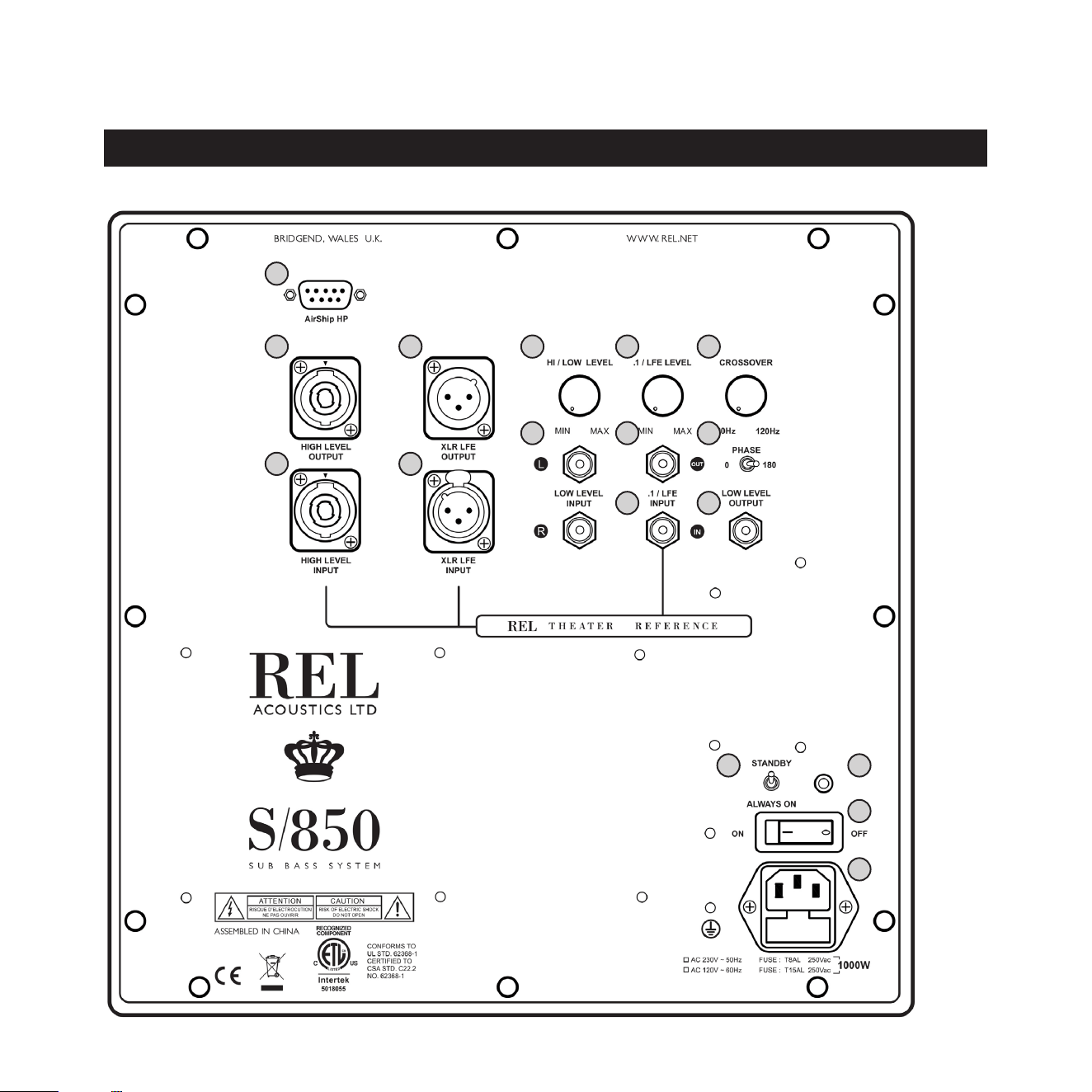
REL SerieS Rear Panel Connecon Legend
8
9 10
11
12
13
14 15
16
17
1
2
3
4
5
6 7

10
1 Airship Direct input connector: Connecon for external REL AirShip wireless receiver.
2 High Level Output (Neutrik Speakon): Used to connect or “daisy chain” another REL Serie S in tandem.
3 High Level Input (Neutrik Speakon): Used to connect to the main front amplier speaker terminals.
4 .1/LFE Balanced Output: Balanced (XLR connector) version of .1/LFE Output. For use only with fully
balanced cables.
5 .1/LFE Balanced Input: Balanced (XLR connector) version of .1/LFE Input. For use only with fully bal-
anced cables.
6 Hi/Low Level: Volume control for High/Low Input. Use to adjust output when using either High Level
or Low Level input.
7 .1/LFE Level: Used to adjust output level when using .1/LFE input from a surround-sound processor.
8 Crossover: Used to adjust crossover frequency of Hi/Low Level channel. Variable between 20-120Hz.
9 Le & Right Channel Low-Level RCA Input: Used to connect low-level signals to the sub-bass system
from the output of a preamplier, integrated amplier or receiver. (For home cinema use, use .1/LFE
input).
10 .1/LFE RCA Output: Used to connect or “daisy chain” another REL Serie S in tandem
11 .1/LFE RCA Input: Used to connect to the .1/LFE output of a surround-sound processor.
12 Phase: Used to set phase 0-180 degrees.
13 Low-Level RCA Output: Used to connect or “daisy chain” low-level signal to another REL Serie S in
tandem
14 Standby/ Always On Switch: Used to enable standby mode.
15 Power Pilot Light: Power On/O indicator.
16 Power On/O Switch: Use to turn unit on or o.
17 .IEC Mains Socket: Fused mains (AC) input socket that accepts detachable power cord.

11
Connecvity and Funconality
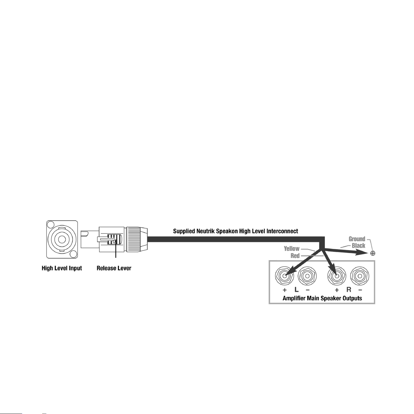
High Level Input
Stereo Amplier: Connecons should be made to the same posive (usually RED) binding posts on your
main amplier as are your main speakers. Please invesgate the design of the amplier(s) you are using be-
cause balanced dierenal and Class D designs require special connecons*. For all amplier classes (Class
A/B, Class D, G or H or Balanced Dierenal) design ampliers, connect the red wire to amplier main right
speaker + (red) terminal, yellow wire to amplier main le speaker + (red) terminal.Black (Ground) wire
should connect to any chassis ground bolt or screw that results in a solid ground connecon that results in
no hum. Plug the Neutrik® Speakon® plug into the HI LEVEL Speakon® socket.
Mono Block Ampliers: A single Serie S unit should not be connected to a pair of mono block ampliers as
the ground dierenal resulng from this will, at a minimum, run the risk of creang hum from a ground
loop. In some instances, this dierence in ground potenal can lead to oscillaon. Please always use dual
REL Serie S when using mono block ampliers.
*Note: Incorrectly connecng the REL High Level cable because of failure to idenfy the Class of amplier can lead to damage to
your REL. If in doubt, please contact the manufacturer of your amplier and request informaon to determine the correct type of
amplier class that is used.
.1/LFE Input
This requires a RCA to RCA or XLR to XLR cable and is a dedicated true .1/LFE channel. This circuit therefore
eliminates the normal Naturalsound RollO™ Crossover and passes the .1 low-level signal through with only
the required 120Hz fourth-order lter.
Low-Level Input
The RCA Low Level Stereo inputs allow for convenonal connecon from a preamplier. Plug one end of
the RCA cables into the LOW LEVEL INPUT jacks of the REL and the other end into the le or right channel
output of your preamplier or powered speaker.
Phase Switch
Used to set phase. Phase selecon aects High Level, Low Level and .1/LFE inputs.
PHASE SELECTION AFFECTS BOTH HIGH AND LOW LEVEL INPUTS
Crossover is always engaged for high and low level inputs. The .1/LFE signal does not pass through the
crossover circuit.

12
Always switch o your system before disconnecng any wires.
To increase the versality of connecon, the Serie S models have three separate and disnct types of inputs,
although only two will be used as one must decide between High Level and Low Level inputs. They are:
1 High Level Input connecon which uses a Neutrik Speakon terminal.
2 .1/LFE input consisng of your choice of RCA or XLR connectors.
3 Low Level stereo or mono (if using stereo pairs or Line Arrays of Serie S RELs) inputs. These in-
clude RCA connecons for stereo input, although if using stereo pairs or Line Arrays of Serie S
RELs only one input per channel need be used. This is to facilitate use with both two-channel
stereo systems as well as AV surround sound systems.
The High Level, unbalanced, dual-channel (stereo) input is via a Neutrik® SpeakOn® connector and is de-
signed to accept the stereo (two-channel) signals from the speaker terminals of your receiver, integrated
amplier or basic amplier. This has the advantage of ensuring that your subwoofer receives precisely the
same signal as the main speakers, which means that the character of the bass from the main system is car-
ried forward into the Sub-Bass System.
This is a very important point which, when combined with REL’s Naturalsound™ input lters, ensures far
superior system integraon of your REL Sub-Bass System with the main system.
URGENT NOTE: Plugging in the REL High Level Cable: Prior to doing so please STOP and carefully examine
the end of the cable’s connector. Idenfy the keyway on the end of the plug and take care to align the key-
way with the matching slot on the rear panel SpeakOn High Level Input. To engage the Neutrik® Speakon®
plug, insert it carefully into the Speakon terminal on the rear panel of your REL and rotate it clockwise unl
it clicks.If any noceable resistance is encountered, please stop, reexamine the orientaon of the cable’s
plug to the Speakon terminal on your new REL and take care to match the keyway and slot before damage
occurs.
Connecng Up

13
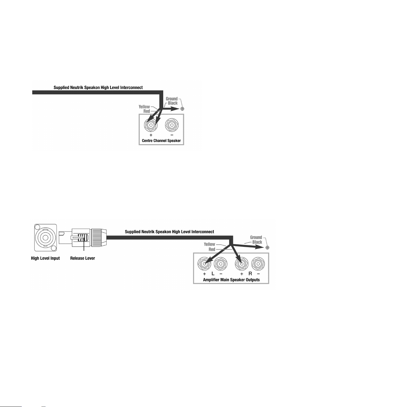
How to Properly Detach the REL High Level Cable from the REL Subwoofer: To remove the Neutrik® Speak-
on® plug, rmly grip the body of the plug, placing thumb on serrated chrome lever. Slide lever rearward
while rotang plug counterclockwise 1/4 turn and withdraw.
XLR and RCA connecons are provided for input from the .1/LFE channel of a home cinema processor.
HIGH LEVEL and .1/LFE inputs can and should be used simultaneously in Theatre Applicaons. The benets
are two-fold when used with a home cinema processor set to Full Range or as low as your processor or re-
ceiver will permit. The .1/LFE input reproduces the .1/LFE channel, and the High Level connecon underpins
the main front speakers. The main front speakers should be set to the ‘large’ or full range if available opon
on the AV processor. See “Theatre Applicaons” for more informaon.
There are two RCA sockets for low-level Le and Right channel connecon to the output of a stereo pream-
plier or receiver. These may be used in cases where High Level input is not an opon.

14
REL products are not tradional subwoofers, but true Sub-Bass Systems. A REL is designed to augment the
performance of “full range” speaker systems in order to provide, in certain cases, linear response below 15
Hz. Therefore, for the moment, please set aside everything you’ve been taught about subwoofers and how
they are integrated into a stereo or home cinema system. REL Sub-Bass Systems set-up and posioning dif-
fers from convenonal subwoofers. A REL will take advantage of physics and room acouscs to provide deep
pressurizaon as no tradional subwoofer can. It is important that you bring to the set-up process a willing-
ness to do things a lile dierently to obtain these superior results. The end result of your labor will be an
uerly seamless integraon of true deep bass to a sound system, regardless of the main speakers’ low bass
capability.
Basic set-up should take no more than ten to een minutes to accomplish once connected.
Two Things Before You Begin
1 I t is helpful to know that you will almost always connect the REL to the input on the rear panel labeled
“HIGH LEVEL INPUT.” This connecon is made using the supplied 32’ 10” (10 meters) cable, the bare
leads of which connect to the speaker output terminals of the power amplier. The easy and foolproof
connecon at the REL is done with a Neutrik® Speakon® connector. The purpose of connecng to the
speaker output terminals is one of the unique secrets of REL’s success. By connecng to the High Level
input on the REL from the amplier, you build forward the sonic signature of your main system, includ-
ing the tonal balance and ming cues of the enre electronics chain. In this way, the REL is fed the exact
signal that is fed to the main speakers.
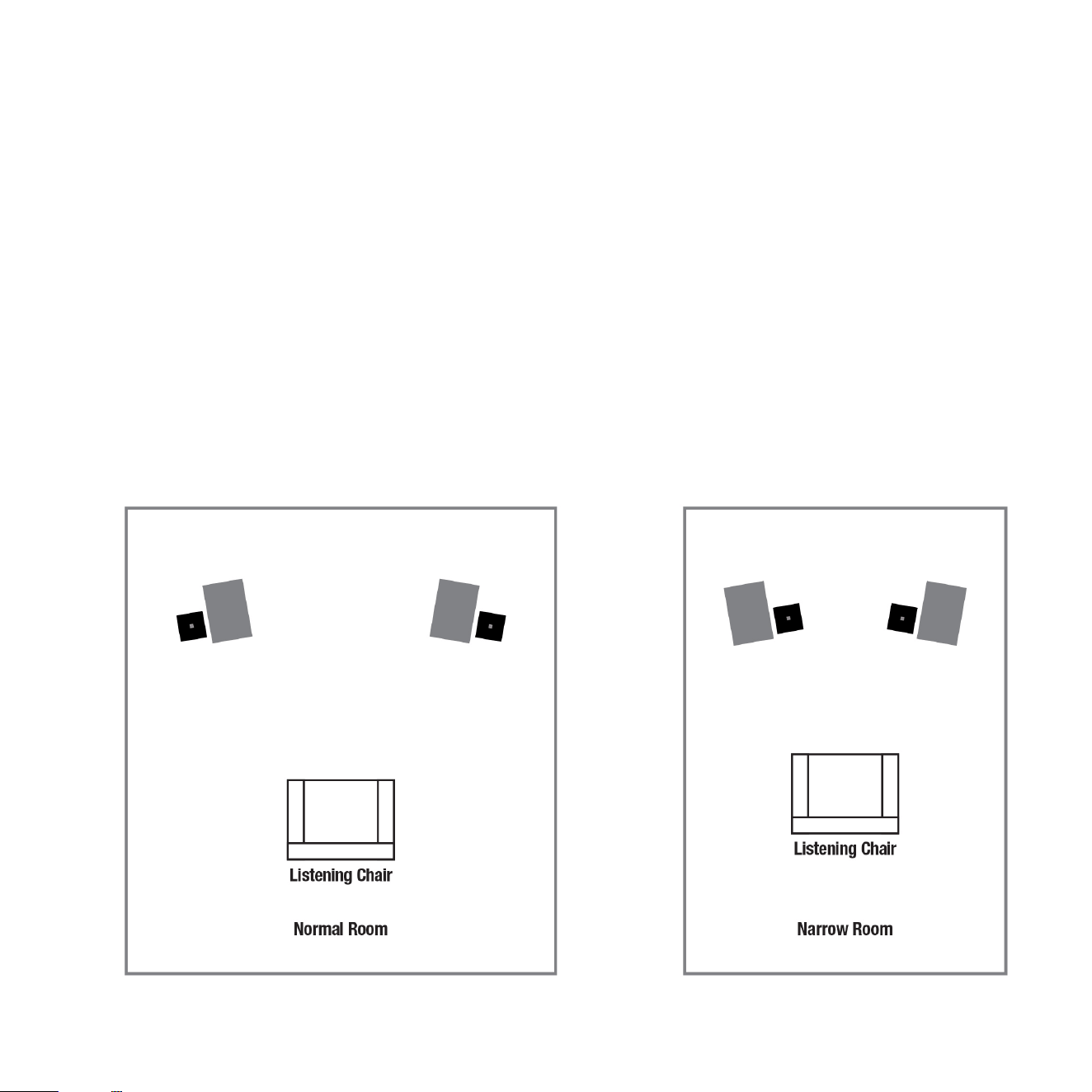
2 When possible, the REL should be placed in one of the corners behind the speakers. Remember, we are
dealing with true LOW bass pressurizaon with RELs. Low bass pressurizaon below 40Hz is best derived
from corner placement, where the most linear and ecient low bass can be produced because the sub-
woofer is able to take advantage of the tangenal (corner-to-corner) axis which is typically the longest
axis in a room.
REL Set-Up Made Simple
Connecng and Seng Up
High Level connecon, using the enclosed cable with the Neutrik® Speakon® connector, is always the rst
choice. This connecon can be made without aecng the performance of the amplier because the REL’s
amplier has very high input impedance, in eect producing NO addional load on the rest of your system.
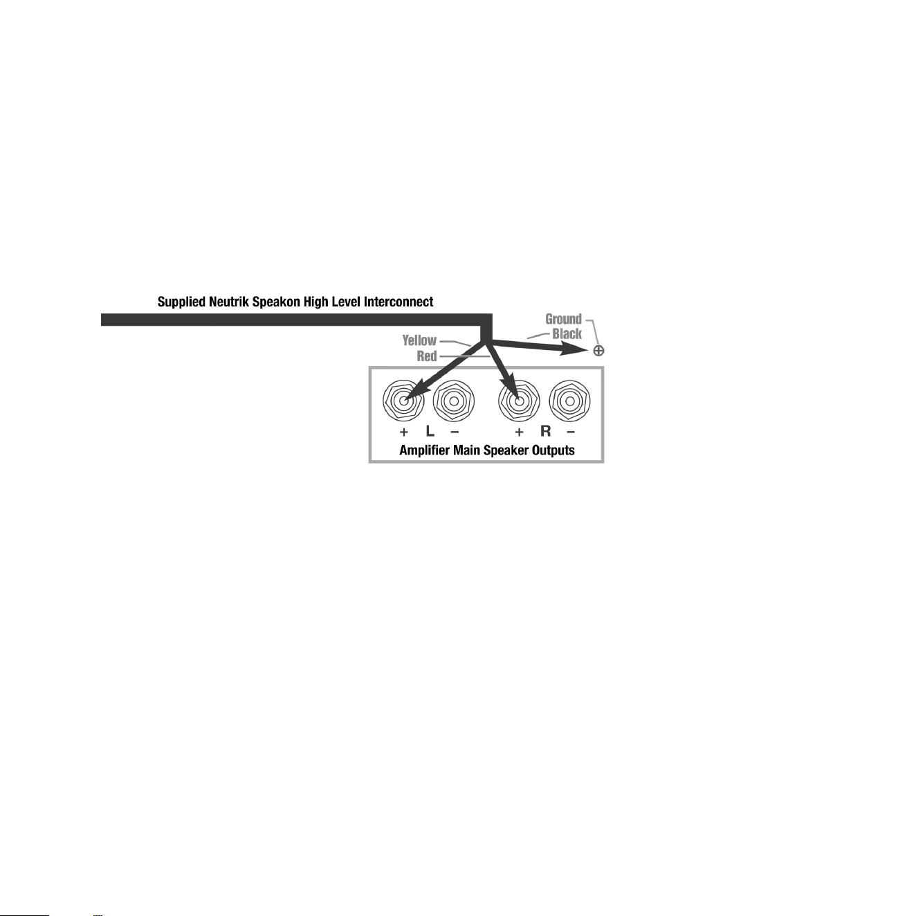
• The standard High Level hook up procedure is aaching the red wire to the amplier’s right posive
speaker output terminal; aach the yellow wire to the amplier’s le posive speaker output terminal;
aach the black wire to whichever of the amplier’s chassis ground screws or bolts is convenient; plug the
Speakon® connector into the Sub-Bass System’s HIGH LEVEL INPUT.
15
Standard High-Level
16
• For dierenal (i.e. fully balanced) stereo ampliers using one REL, simply use the standard connecng
scheme of connecon to an exposed chassis ground screw or bolt. It may also be allowed to “oat” or hang
down without connecon to ANY terminal. Should hum occur using this method, please return to connect-
ing to chassis ground or an unused RCA connector on the rear of a preamp or amplier. Please contact your
dealer should there be any quesons concerning this or any other hookup procedure.
NOTE: Serie S models are equipped with internal circuitry to allow connecon to many Class-D (digital)
ampliers.
Warning: Do NOT connect the Black wire to the main Class D power amplier’s speaker ground terminal.
Some Class D ampliers produce posive voltage at the amplier’s speaker ground terminal (black) and
connecng the REL’s ground will produce an undesirable shorng to ground. If connecng to a Class-D
amplier, follow the above connecon procedure for dierenal ampliers.
• When connecng RELs to Mono Bloc ampliers (2) RELs, one for each amplier, must be used. Connect
Dierenal (i.e. Fully Balanced)
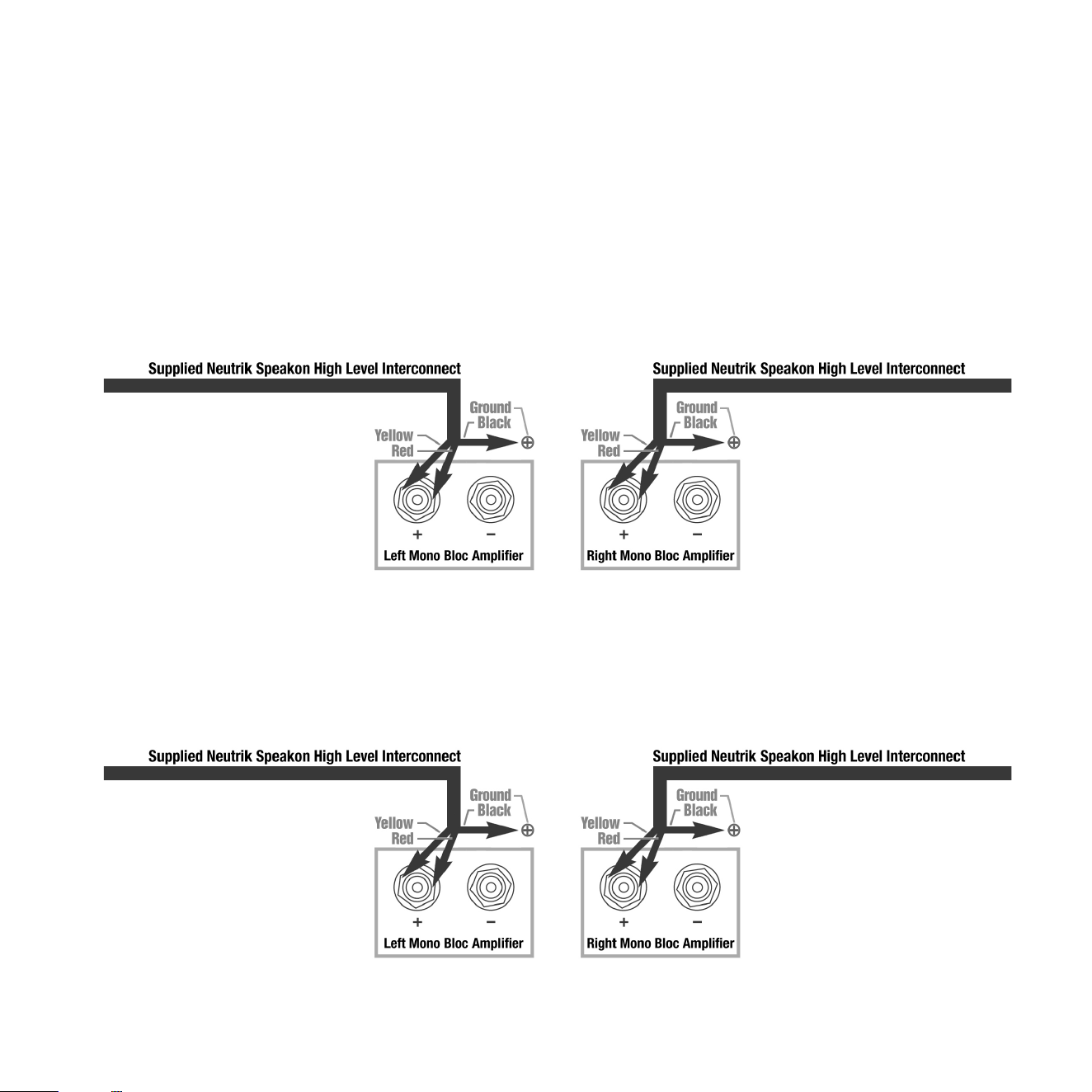
the black wire of each REL to chassis ground screws or bolts of the corresponding amplier channel; twist
together the red and yellow wires of each REL separately and connect each pair to the posive speaker
terminal of the corresponding amplier channel. In some instances, this will result in exceponally high gain
(output) from the RELs. If it seems simply too high in gain, please remove either the red or yellow wire from
the twisted pair. This will reduce output by half and restore a natural dynamic.
If the amplier is of balanced dierenal design, please follow the instrucons in the secon above labeled
Dierenal Connecon.
• If connecng a single REL as a dedicated centre channel sub, twist together the red and yellow wires and
17
Mono Bloc Connecon
Mono Di Connecon
18
connect these paired wires (red/yellow paired together) to the posive centre channel amplier terminal.
Connect the black wire to a ground lug or chassis screw on the amplier.
• If connecng a REL as a dedicated rear channel sub, connect the yellow wire to the le rear posive
speaker terminal; connect the red wire to the right rear posive speaker terminal, connect the black wire
to a ground lug or chassis screw. If the amplier is of balanced dierenal design, please follow the instruc-
ons in the secon above labeled Dierenal Connecon.
Low-level connecon (via RCA connectors) is always an opon if High Level connecon is not possible.
When connecng to the low-level inputs in a system in which High Level connecon is not possible, such as
if using internally amplied speakers, connect le and right RCA cables between the LOW LEVEL INPUT jacks
of the REL and the le and right channel outputs of your preamplier.
When connecng to a home cinema system where there is a .1/LFE channel output, connect a single RCA to
RCA or XLR to XLR cable between the sub output of the processor/receiver and the .1/LFE input jacks on the
REL.
Posioning Single Serie S for Best Results:
Rear Connecon

19
The opmal posion for a single REL Serie S is in one of the corners behind the main speakers. This posion
provides 9 dB of room gain and allows for the best low bass extension. Do not simply place it as close to the
walls as possible. Instead, once basic opmizaon of Phase, Crossover and Gain have taken place, carefully
move your REL in small increments whilst using cut #4 on the CD soundtrack of the movie Sneakers. Listen
for pressure-driven nodes. Choose the one that oers the best combinaon of deep bass with speed and
delicacy.
Corner Placement Fine Tuning: The rst step is to determine precisely how far from the corner the sub
should be placed to achieve the most ecient output, as well as the lowest frequency extension. With the
REL fully loaded into the corner, and toed in toward the listening posion, connue to play music while
slowly drawing the REL out from the corner on the diagonal. As you do so, note certain points (somemes a
maer of only a few inches, in rare cases a foot or more) where the REL will audibly go lower, or play louder,
and, if it truly locks on to the room and is fully pressurizing it, the air around the REL will feel more ener-
gized. Stop right there! This is the correct posion from the corner for the REL.
Orientaon, Fine Tuning Toe-In: Once the posion from the corner has been established, the toe-in of the
REL must be determined by rotang the REL from an imagined centre point at the rear of the REL. As the
REL is toed in from one side to the other, listen for the greatest level of output and bass linearity. In eect,
the REL should be le in the posion where it sounds both the richest and most focused. If your room is too
full sounding, slightly toeing your REL out will result in reducon of richness but may be more desirable in
rooms that output too much bass.
Posioning Dual Serie S for Best Results
Stereo Sub-Bass is advised for the fastest, clearest, deep bass—not simply for more output. Convenonal
wisdom has it that the use of stereo subs results in between +3 and +6 dB addional output depending
upon posioning. In and of itself, this is of only passing interest since, in most instances, even a single Serie
S is capable of profound output. What then, is the point to adding a second bass sub in stereo?
In a word, clarity. Clarity that permits “seeing” back into the farthest reaches of the sound stage. Clarity
20
that illuminates all dimensions of the musicians and the space that they inhabit equally and enhances the
natural reality of a great full range system, as only RELs can. Stereo Serie S and Line Arrays, oen referred
to as 6-Packs, produce clarity, transparency, speed and low level detail NOT just in the bass but throughout
the enre spectrum of music. The advice to disconnect all signals to all but one subwoofer becomes crical
when seng up Line Arrays.
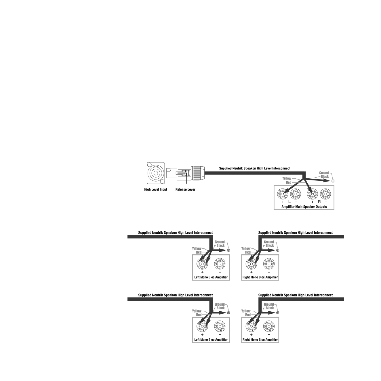
Set-Up: When seng up stereo Serie S, it is possible to place both units in the front corners of the room
carefully toed-in and placed per normal guidance in this manual. Connect each sub to the speaker terminal
outputs based on the following diagrams for standard stereo amp, non-balanced mono blocks or balanced
dierenal mono blocks.
Dierenal (i.e. Fully Balanced)
Standard High-Level
Mono Bloc Connecon
21
Expert Set-Up: Depending upon your room’s character, it may be preferable to bring the subs further out
into the room and place them slightly behind and outboard of the main speakers.
1 Set each side up independently. Disconnect the sub that is not being set-up at that moment so your
complete focus can be given over to the sub that is being set-up. Carefully follow the guidance provided
in standard set-up if you are unfamiliar with standard REL set-up procedure for gain, phase and crossover
sengs. (see page 15 thruogh 20 for Standard Set-Up procedure).
2 Carefully ne-tune the posion of the sub in its recommended locaon (slightly behind and to the outside
of the main speaker) listening for rich powerful room nodes, but focusing on speed and connecon with
the main speaker. Since there will be a preponderance of output available to a stereo Serie S owner, focus-
ing on connecon with and blending with the main speaker becomes the primary focus, not merely raw
output.

22
3 Once each sub has been carefully tuned, aach the cables for both subs. At this point, the output
achieved will be too loud and will require re-seng the volume/gain control of Serie S normal as the
combined output is likely to be at least 3 dB louder with both subs now being used. Carefully turn down
each sub unl the perfect balance is achieved. While turning the le or right sub gain down, it is helpful
to turn slightly and even lean slightly toward the side that is being adjusted to beer achieve focus and a
balanced sound level more quickly.
Setup: The Process
To begin the set-up process, select a piece of music that has a repeve bass percussion line that is very low
in frequency. We exclusively use track 4 from the soundtrack to Sneakers (Columbia CK 53146), it is the best
REL setup track we’ve ever found and works perfectly for dialing in Phase and Crossover values. This has a
repevely struck bass drum that appears throughout and that gives one plenty of me to move the woofer
around whilst listening and making adjustments. Due to the very deep nature of this instrument’s bass, it
consistently allows for accurate seng of crossover and gain. This track is perfect for the set-up process and
should be played at a high enough level to drive the room hard, but short of doing damage to speakers or
REL. Work with one REL connected at a me. Only aer each is opmized should both be connected and
gain reduced 1-2 clicks to re-establish proper gain.
1. Phase Orientaon:
Once in the corner, we need to adjust for phase. This may be the single most crical step, and because it is
so simple, it is oen over-thought. Keep in mind; the correct phase is whichever seng (0 or 180 Degrees) is
the loudest or fullest. While playing Sneakers, cut #4, adjust Hi/Low Level to a point where the REL and the
speaker appear to blend at the REL. During this process, leave the Crossover at its lowest seng as this en-
sures that you are correctly achieving a Phase result based on deepest bass. Simply switch between “0” and
“180” phase posions listening for whichever posion is loudest or fullest. This is the correct posion. That
is, this is the posion that is working in harmony with your main speakers, reinforcing bass, not cancelling it.
RELTip: Do NOT get caught up in aempng to assign audiophile virtues to the sound quality of bass (“Oh,
the bass sounds lighter and more delicate in such-and-such phase seng”). Phase is an essenally digital
reacon, the purpose being to arrive at a seng wherein the REL is acng as a piston in concert with one’s
main speakers. Doing so results in louder output. Simple.

23
2. Crossover and Level Sengs:
To determine the crossover point, take the volume of the REL (using the HI/LO Level control) all the way
down, and set the Crossover to 10 o’Clock (1/3rd total rotaon) as an inial seng. Now, begin adjusng
the volume back up slowly to the point where you have achieved a delicate balance, i.e. the point at which
you can just hear the Serie S even with the main speakers playing. We suggest bringing the crossover point
up unl it is obviously too high; then gently reducing frequency unl the perfect balance has been achieved.
For all intents and purposes, this is the correct crossover point. Once this stage has been reached, subtle
changes to volume and crossover may be accomplished to provide the last bit of complete and seamless
integraon. With that, set-up is complete.
RELTip: One of the persistent myths regarding sub bass is that “One should never hear the subwoofer if it
properly set.” Fair enough, but for those trying to set up their sub, this is useless advice. Aer all, leaving
one’s sub unplugged would sasfy that guidance. Instead, know that proper Crossover seng is achieved
when a melding of both deep bass and music from one’s speakers occurs. It actually does change slightly
(and with experience, one will nd this is for the beer and more accurate). When it’s perfectly crossed
over, a very slight richness comes over the music. One crossover frequency click lower and this is replaced
by a very slightly cool, mechanical quality.
Addional Listening Tips: There is a tendency to set the crossover point too high and the level of your
Serie S too low when rst learning how to integrate a REL with the system. The most common fear being
one of overwhelming the main speakers with bass. In making this common error, the resulng set-up will
be lacking in deep bass, rather overly emphasizing middle bass which will result in lack of integraon and a
too thick and plummy quality to your system. The proper crossover point, and volume seng will increase
overall dynamics, allow for extended bass frequencies, and improve soundstage properes. Note, volume
adjustments may need to be made to oset the eects of crossover changes. In general, when selecng a
lower crossover point, more volume will need to be applied. Higher crossover frequencies will require less
gain.

24
Stacking
REL Serie S are designed to allow mulple units to be used in conjuncon either as stereo pairs or, for ul-
mate performance, in vercal tower stacks of stereo subs 3 per side. Stacked towers extend and strengthen
the performance remarkably.
REL Couplers are provided to secure the top sub to the next unit below safely. These are made of thick alu-
minium and bolt the subs together using the hardware provided. The Couplers require a 6mm hex wrench
to ghten.
We strongly advise anchoring Line Array stacks of the Serie S to a wall. Use a quality furniture restraint
made of nylon webbing or braided steel cable that may be ed to one of the upper REL Coupler, generally
that which is closest to a side or rear wall. Please follow the instrucons of the restraint you choose and
anchor to a structural poron of your wall.
hps://www.consumerreports.org/furniture/how-to-anchor-furniture-to-help-prevent-p-overs-
a4328328212/
To help sele Serie S on so oors, each unit has leveling discs installed into the foot rails near the boom
front. If needed, these can be backed out by rotang them counterclockwise to help level the subwoofer. If
these are needed to help level a stacked line array, only the boom unit should employ the leveling discs.
The units stacked on top should not have their leveling discs backed out.
Please ensure that the oor is level before stacking REL reference subwoofers and avoid stacking on deep
carpet that may not provide a stable surface.

25
Connecvity for Line Arrays of Serie S, Mulple Sub-Bass Systems
To render connecvity simple, Serie S provides both inputs and outputs for all connecons. Thus, each
channel’s stack of Serie S can be connected using only one High Level main cable from power amp to REL
stack. When “daisy chained” each sub-bass system retains its autonomy and each will need to have its out-
put level, crossover point, phase, etc. adjusted individually.
Theatre Connecvity for Line Arrays of Serie S, Mulple Sub-Bass Systems
In a .1/LFE lm sound conguraon, each channel will require a single.1/LFE cable (either XLR or RCA con-
necons are included) per L/R channel as well, but addional unit’s .1/LFE connecons in a tower may be
daisy chained to minimize cluer. Stacked Serie S subs have the ability to eortlessly energize even very
large theatres with huge wavefronts of air that will carry sound to the full height of the screen, an eect
best demonstrated by removing the top level of subs, followed by the middle level to hear on screen events
descend in their posioning. Serie S Line Arrays possesses the ability to convey the musical event or lm
sound spectacularly and with great ease.
Theatre Applicaons
For Dolby Digital AC3 or other 5.1 theatre systems, once the standard set-up for the two-channel outlined
above is complete, the LFE output from the processor or receiver should be connected to the .1/LFE INPUT
and appropriate volume adjustments made using the .1/LFE level control. For this conguraon, you must
set the processor to the “large” or “full range” seng for the le and right speakers in order for the REL to
receive the bass signal via the High Level cable. In this conguraon, the REL provides support for both the
le and right speakers for two-channel listening, and support for the LFE when movies are playing. Most
processors will allow you to defeat the subwoofer output when listening in the two-channel mode. The ef-
fect of this set-up is one of greatly increased dynamics in the mid-bass range, no bass bloat, and a greater
degree of space and ming from the special audio eects. For an even greater sense of space and impact,
a second REL connected in parallel to the centre channel will prove to be a dramac improvement as well.
And if that is not enough, a rear REL, both to support the rear channel speakers as well as to evenly distrib-
ute LFE through the room, truly completes the full-range sonic picture for state-of-the-art lm reproducon.

26
Running In
The care taken during run-in will be rewarded by many years of pleasurable use. Both the electronics and
the drive unit will benet from an inial period of carefully controlled use. Possible damage may be sus-
tained by running in the unit at too high a volume seng over an extended period. On the other hand, by
taking a lile care over this inial period, about 24 hours of actual use, a longer life with a higher potenal
eventual performance is assured.
Care and Polishing
The cabinets are best maintained by using an automobile polish made by reputable manufacturers. Our
favorites are those made by Meguiars and Mother’s. If objects are to be placed upon the top, it is advisable
to use a small mat to protect the surface and to avoid the risk of rales.

27
Overload Protecon
All REL Sub-Bass Systems are designed as true sub bass speakers. They are designed to reproduce those ex-
ceponally deep notes that are felt as well as heard. This it will aempt to do at whatever volume level you
set. If set too high no damage should result because the built-in electronics will limit the cone movement.
This electronic control is called Set-Safe™. It constantly and instantaneously monitors the output from the
power amplier and is totally transparent in operaon unl required. This means it has absolutely no eect
on the sound quality of your REL unl an overload is detected.
Ordinarily an overload would cause the power amplier to go into clipping with resultant loss of control
over the drive unit. This can cause drive unit damage and always sounds nasty. Set-Safe™ detects the point
of incipient clipping and gently so-clips the waveform of the signal to ensure actual clipping does not oc-
cur.
This is a necessarily simplied descripon of what actually happens, but in eect, Set-Safe™ controls the
amplier and ensures there is minimum risk of amplier and driver damage caused by over-driving.
A thermal overload device is ed to all Serie S Sub-Bass Systems. If the unit is deliberately over-driven this
device will sense the temperature rise and cut the output; recovery me is approximately ve minutes.
If this happens, it is a warning that the unit is being over-driven, and the volume level control should be
reduced to a safe level.
Although everything possible has been done to minimize the risk of thermal overload failure, there can be
no defense against those individuals who deliberately abuse the device. Such damage is NOT covered by
warranty. Please remember your REL is there to supplement your main system, not overwhelm it!
28
Power Saving Eciency
All REL sub bass system designs ulize a true On-O switch that aords the owner the ability to turn o
their unit completely, without having to unplug the A/C mains cord. When a REL sub bass system is switched
o using the On-O switch on the rear panel it draws ZERO power.
In addion to the ecient power-at-idle exhibited by all REL models, the Serie S also features an automac
standby mode that is enabled when the power mode switch on the rear of the unit is set to the “STANDBY”
posion. In this mode, the input signal is constantly monitored for audio acvity. If not audio informaon is
detected over a period of 30 minutes, the unit will enter a low power standby mode in which less power is
consumed. When input signal acvity is detected, the unit resumes normal operaon. By using the stand-
by mode, you can ensure that there is no unnecessary power draw when the unit is not in use.
Note: Due to variaons in program material, it is impossible to produce a perfectly reliable standby circuit.
Bass rich music or eects will consistently trigger our standby circuit whilst content that is low in volume
and possesses lile or no bass cannot be relied upon to trip the standby funcon.
Alternavely, the user has the opon to leave the unit in the normal operaon mode at all mes by select-
ing the “ALWAYS ON” posion of the power mode switch. Leaving a REL on, produces the best sonic perfor-
mance and the most reliable operaon. In this mode, the unit will not enter standby regardless of whether
or not there is acvity at the input. Using this seng ensures that the Serie S is ready to react instanta-
neously to bass transients, whether in music or lms.
The REL Serie S is shipped in the “ALWAYS ON” mode. During inial setup, use the REL this way. Aer inial
setup, if you wish to employ the standby mode, simply move the power mode switch into the up posion to
“STANDBY”.
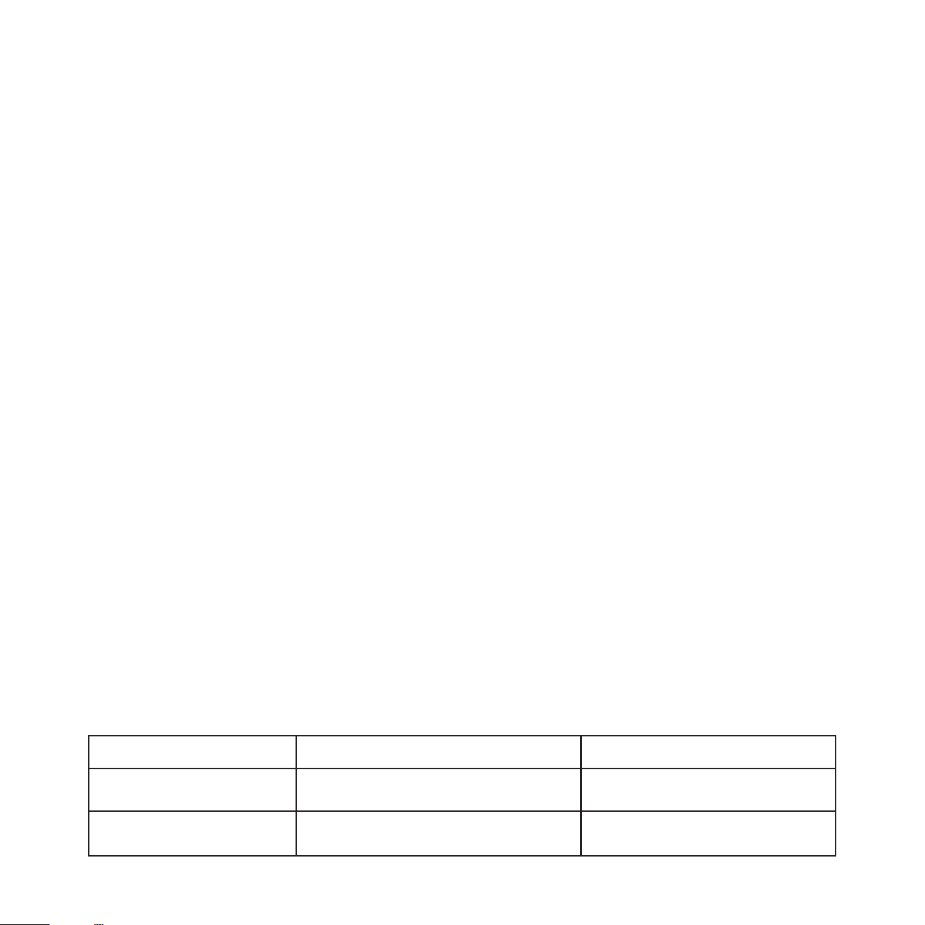
Model
S/850
S/550
>0.5 Was
>0.5 Was
Power Draw at Idle
20 Was
13 Was
Power Draw at Standby

S/850 Specicaons
Type: Front-ring acve driver, down-ring passive radiator
Acve Drive Unit: 12 in. (305mm) long-throw, CarbonAlloy™ cone structure, die cast alloy chassis
Passive Radiator: 12 in., (305mm), Carbon/Carbon at cone structure, steel chassis
Lower Frequency Response in Room: -6 dB at 19Hz
Input Connectors: High Level Neutrik Speakon, Le and Right Low Level phono, LFE phono, LFE XLR
Output Connectors: High Level Neutrik Speakon, , Low Level RCA, LFE XLR
Gain Control Range: 80 dB
Power Output: 850 was (RMS)
Phase Switch: Yes, 0 or 180 degrees
Amplier Type: Linear Class D
Wireless capability: Yes- REL AirShip [required]. Sold separately.
Protecon System
Fully Electronic with SET-SAFE: Yes
D.C. Fault: Yes
Output Short: Yes
Mains Input Voltage: 220-240 volts, 110-120 volts for certain markets
Fuses: 8 Amp semi delay 220 volts operaon, 15 Amp semi delay 120 volts operaon
Dimensions
W x H x D, Including Feet and Rear Panel Controls: 19.25 x 16.125 x 21.25 in., (488 x 410 x 540 mm)
Add 1.75in (44.5mm) in depth when using Hi Level connector
Net Weight: 93.5 lbs. (42.5 kg)
Finish: Piano Black Lacquer or Gloss White Lacquer, 8 coats
Supplied Accessories
Mains Lead: Yes
Neutrik Speakon Interconnect 10 Metres Nominal: Yes
Users Manual: Yes
29

S/550 Specicaons
Type: Front-ring acve driver, down-ring passive radiator
Acve Drive Unit: 10 in. (250mm) long-throw, CarbonAlloy™ cone structure, die cast alloy chassis
Passive Radiator: 12 in., (300mm), Carbon/Carbon at cone structure, steel chassis
Lower Frequency Response in Room: -6 dB at 19Hz
Input Connectors: High Level Neutrik Speakon, Le and Right Low Level phono, LFE phono, LFE XLR
Output Connectors: High Level Neutrik Speakon, , Low Level RCA, LFE XLR
Gain Control Range: 80 dB
Power Output: 550 was (RMS)
Phase Switch: Yes, 0 or 180 degrees
Amplier Type: Pure Class D
Wireless capability: Yes- REL AirShip [required]. Sold separately.
Protecon System
Fully Electronic with SET-SAFE: Yes
D.C. Fault: Yes
Output Short: Yes
Mains Input Voltage: 220-240 volts, 110-120 volts for certain markets
Fuses: 5 Amp semi delay 220 volts operaon, 10 Amp semi delay 120 volts operaon
Dimensions
W x H x D, Including Feet and Rear Panel Controls: 17.5 x 14.75 x 19.75 in., (445 x 372 x 500 mm)
Add 1.75in (44.5mm) in depth when using Hi Level connector
Net Weight: 68 lbs. (31 kg)
Finish: Piano Black Lacquer or Gloss White Lacquer, 8 coats
Supplied Accessories
Mains Lead: Yes
Neutrik Speakon Interconnect 10 Metres Nominal: Yes
Users Manual: Yes
30