TJ05 Thermal Controller User Guide (for TJ05BT & TJ05ST only)
Features/Functions:
1. Temperature Display Function
There are three sets of thermal sensor that can be used for detecting temperatures
from CPU, system, and hard drive (CPU, SYS, and HDD). The LCD screen can
display temperature range from 0 to 100 degrees Celsius or 32 to 212 degrees
Fahrenheit. Additional temperature readouts also include the following:
- Temperature below 0°C Display = LO
- Temperature above 100°C Display = HI
- Thermal sensor disconnected Display = ---
Changing temperature display from CPU to SYS and to HDD is easily
accomplished by pressing on the MODE button.
When enabled, an audible alarm sounds when the temperature reaches a
predetermined level (default setting is 65°C)
2. Fan Speed Monitoring
Fan speed is automatically adjusted by the thermal controller in six levels
depending on temperature detected for each respective CPU, SYS, and HDD
areas.
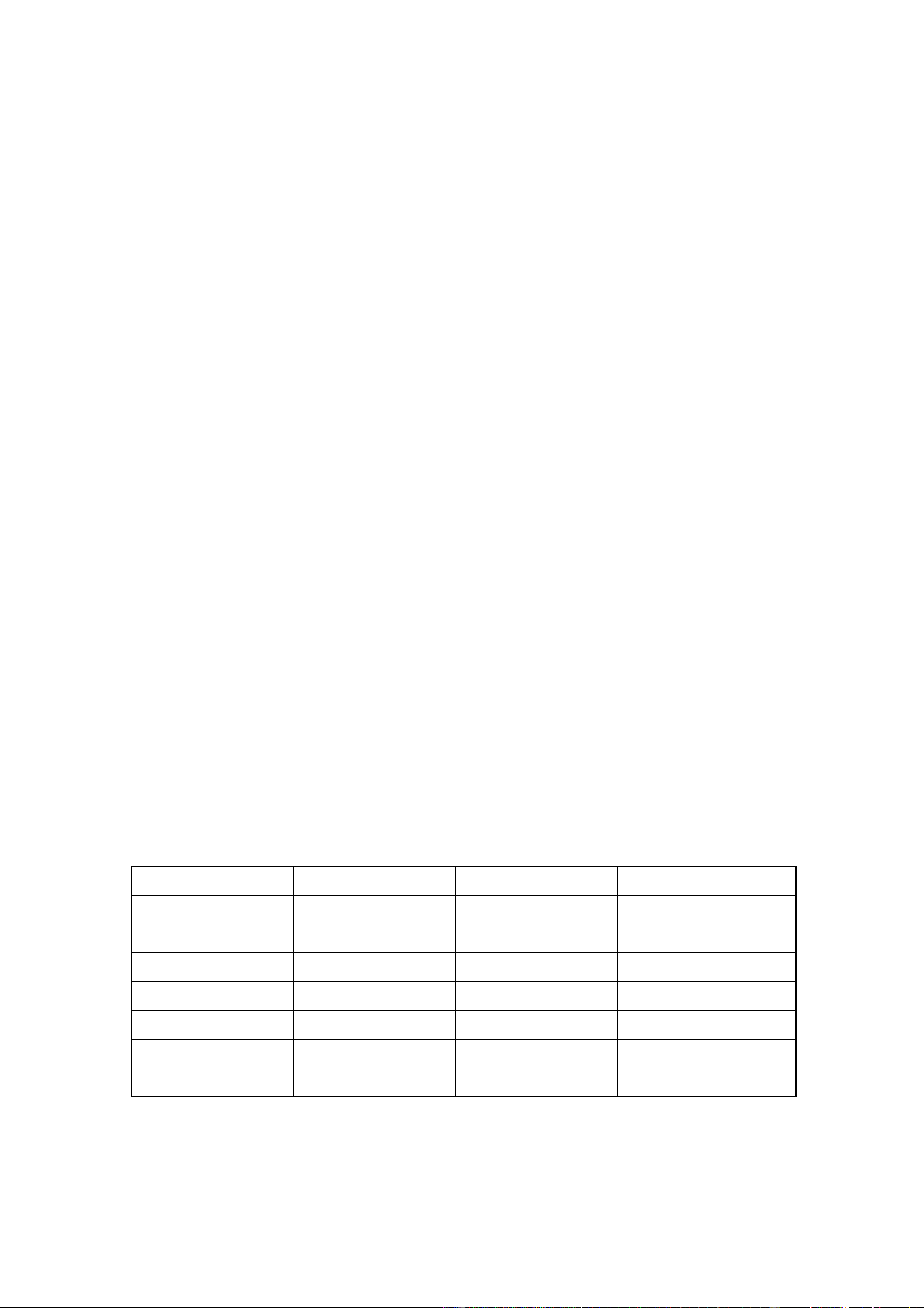
Temperature Fan Speed Level Output Power LCD Display
0 ~ 13°C 0 0V No fan movement
14 ~ 19°C 1 6V Very slow fan speed
20 ~ 25°C 2 7.5V Slow fan speed
26 ~ 31°C 3 9V Medium fan speed
32 ~ 37°C 4 10V Fast fan speed
38 ~ 43°C 5 11V Very fast fan speed
44 ~ 50°C 6 12V Maximum fan speed
When the sensor is disconnected or damaged, fan speed will automatically be
adjusted to level 6 and the LCD display will show no fan movement.
3. Time Display
The date and time status in the LCD screen is displayed in 24 hour format. An
alarm clock function is included with the controller to provide extra convenience
and versatility.
4. System Status Display
There are redundant “POWER LED” and “HDD LED” connectors included with
the thermal controller. If connected, the LCD screen can display power and
HDD activity.
Pin & Cable Installation:
Please operate and install this device under static-free environment and take great care
in the use of the glass LCD screen. The integrated TJ05BT/ST thermal controller is
powered by both +12V and +5V rails from the power supply via one 4 pin connector.
Connected fans are powered by +12V and the backlighting for the LCD is powered by
+5V. The included CR2032 battery is used to maintain the clock and system settings
after the computer is powered off. When connecting or re-routing wires be sure to
turn off your computer before proceeding.
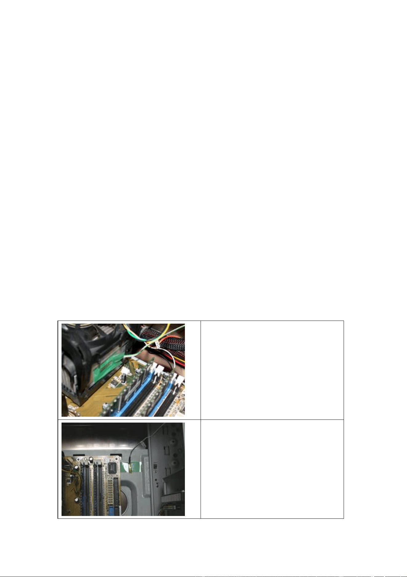
CPU sensor – Place the CPU sensor on
the CPU cooler, preferably on the hottest
part of the heatsink with the least
airflow. It may also be possible to
place it in-between the heatsink and the
CPU for AMD Athlon XP/Duron users.
Use tape to secure the sensor if needed.
SYS sensor – Place the SYS sensor near
the top of the system where the
temperature should be slightly warmer
than the rest of the case. Use tape to
secure the sensor if needed.
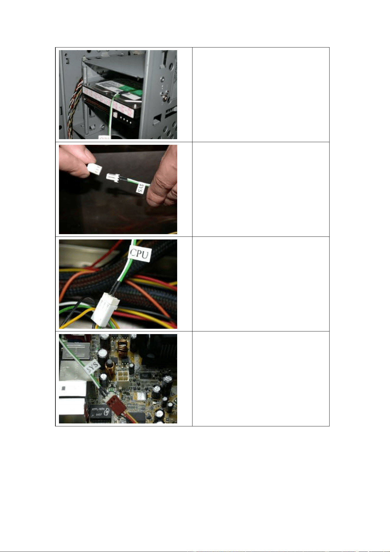
HDD sensor – Place the HDD sensor on
top of the hard drive. If there is plenty
of airflow over the top of hard drive,
place the sensor in other possible hot
area where free flowing air will not
impinge on the sensor from detecting the
correct surface temperature of the hard
drive.
Remove plastic caps from all three fan
connectors (CPU, SYS, and HDD)
CPU fan connector – Connect the CPU
fan connector to the CPU cooler’s 3 pin
wire. Some motherboards may require
setting changes to prevent the system
from shutting off automatically when no
CPU fan is connected to the
motherboard (please refer to your
motherboard manual for more info).
SYS fan connector – Connect the SYS
fan connector to an available 3 pin case
fan that will affect the system
temperature the most.
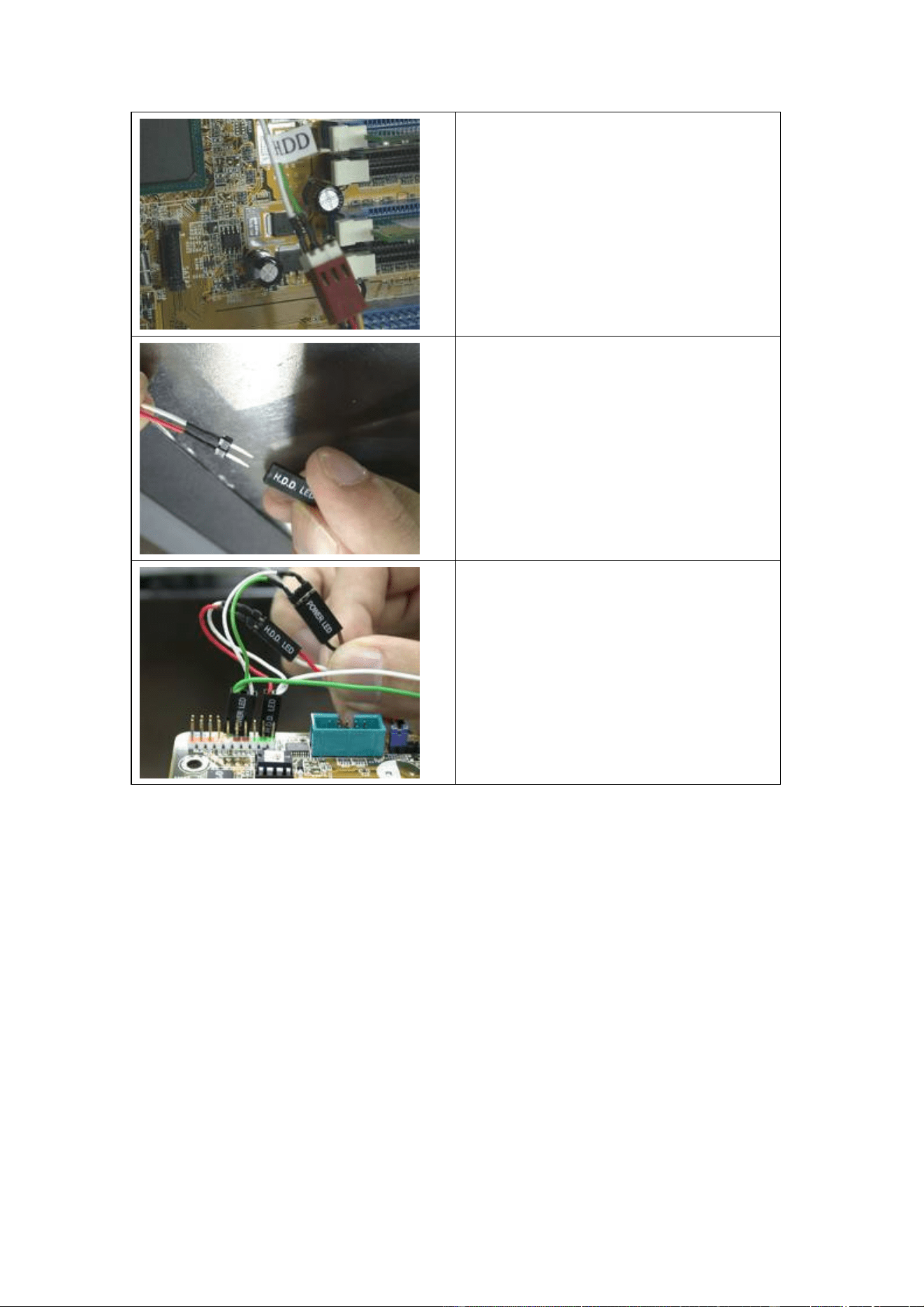
HDD fan connector – Connect the
HDD fan connector to an available 3 pin
fan that has the most affect on cooling
the hard drive whose temperature will be
monitored by the HDD sensor.
Remove plastic caps from both LED
connectors (POWER and H.D.D.)
POWER LED/H.D.D. LED – Replace
the POWER LED and H.D.D. LED
connectors that are already hooked up to
the motherboard from the case with the
ones from the thermal controller. Case
LED cables can be re-connected to the
thermal controller’s corresponding
pass-thru pins.

Operating Instruction:
1. Button Operation and System Setup
A. The MODE button is used to cycle through CPU, SYS, and HDD status
displayed on the LCD screen.
B. The SET button is used to activate or deactivate alarm clock function.
C.
Clock Setup
- To adjust year, press and hold MODE button for 3 seconds until the
number indicating the year starts to flash, then press SET button to
change desired year (range 2000 ~ 2019).
- To adjust month, press and hold MODE button for 3 seconds then press
the MODE button one more time until the number indicating the month
starts to flash, press SET button to change desired month.
- To adjust date, press and hold MODE button for 3 seconds then press
the MODE button two more times until the number indicating the date
starts to flash, press SET button to change desired date.
- To adjust hour, press and hold MODE button for 3 seconds then press
the MODE button three more times until the number indicating the hour
starts to flash, press SET button to change desired hour.
- To adjust minute, press and hold MODE button for 3 seconds then press
the MODE button four more times until the number indicating the
minute starts to flash, press SET button to change desired minute.
D. Alarm Clock Setup
- To adjust hour for alarm clock, press and hold MODE button for 3
seconds then press the MODE button five more times until the number
indicating the alarm clock hour starts to flash, press SET button to

change desired alarm clock hour.
- To adjust minute for alarm clock, press and hold MODE button for 3
seconds then press the MODE button six more times until the number
indicating the alarm clock minute starts to flash, press SET button to
change desired alarm clock minute
E. Temperature Alarm Setup
- To adjust CPU alarm temperature, press and hold MODE button for 3
seconds then press the MODE button seven more times until the number
indicating the CPU alarm temperature starts to flash, press SET button
to change desired CPU alarm temperature.
- To adjust SYS alarm temperature, press and hold MODE button for 3
seconds then press the MODE button eight more times until the number
indicating the SYS alarm temperature starts to flash, press SET button to
change desired SYS alarm temperature.
- To adjust HDD alarm temperature, press and hold MODE button for 3
seconds then press the MODE button nine more times until the number
indicating the HDD alarm temperature starts to flash, press SET button
to change desired HDD alarm temperature.
F.
°C/°F Setup
- To adjust temperature display symbol, press and hold MODE button for
3 seconds then press the MODE button ten more times until the °C or °
F indicator starts to flash, press SET button to change desired
temperature symbol.
G. To exit setup at any time, do not press either two buttons for more than 3
seconds. The LCD screen will automatically return to default system
display.